WO2015125678A1 - リンク作動装置の制御装置および制御方法 - Google Patents
リンク作動装置の制御装置および制御方法 Download PDFInfo
- Publication number
- WO2015125678A1 WO2015125678A1 PCT/JP2015/053739 JP2015053739W WO2015125678A1 WO 2015125678 A1 WO2015125678 A1 WO 2015125678A1 JP 2015053739 W JP2015053739 W JP 2015053739W WO 2015125678 A1 WO2015125678 A1 WO 2015125678A1
- Authority
- WO
- WIPO (PCT)
- Prior art keywords
- link
- end side
- section
- arm
- point
- Prior art date
Links
Images


Classifications
-
- B—PERFORMING OPERATIONS; TRANSPORTING
- B25—HAND TOOLS; PORTABLE POWER-DRIVEN TOOLS; MANIPULATORS
- B25J—MANIPULATORS; CHAMBERS PROVIDED WITH MANIPULATION DEVICES
- B25J9/00—Programme-controlled manipulators
- B25J9/16—Programme controls
- B25J9/1615—Programme controls characterised by special kind of manipulator, e.g. planar, scara, gantry, cantilever, space, closed chain, passive/active joints and tendon driven manipulators
- B25J9/1623—Parallel manipulator, Stewart platform, links are attached to a common base and to a common platform, plate which is moved parallel to the base
-
- B—PERFORMING OPERATIONS; TRANSPORTING
- B25—HAND TOOLS; PORTABLE POWER-DRIVEN TOOLS; MANIPULATORS
- B25J—MANIPULATORS; CHAMBERS PROVIDED WITH MANIPULATION DEVICES
- B25J9/00—Programme-controlled manipulators
- B25J9/16—Programme controls
- B25J9/1628—Programme controls characterised by the control loop
- B25J9/1651—Programme controls characterised by the control loop acceleration, rate control
-
- F—MECHANICAL ENGINEERING; LIGHTING; HEATING; WEAPONS; BLASTING
- F16—ENGINEERING ELEMENTS AND UNITS; GENERAL MEASURES FOR PRODUCING AND MAINTAINING EFFECTIVE FUNCTIONING OF MACHINES OR INSTALLATIONS; THERMAL INSULATION IN GENERAL
- F16H—GEARING
- F16H21/00—Gearings comprising primarily only links or levers, with or without slides
- F16H21/46—Gearings comprising primarily only links or levers, with or without slides with movements in three dimensions
Definitions
- the present invention relates to a control device and a control method for a link operating device used in equipment that requires a precise and wide operating range such as industrial equipment.
- these link actuating devices include a link hub 14 on the proximal end side, a link hub 15 on the distal end side, and three sets of link mechanisms 11 and 12 that connect the link hubs 14 and 15 to each other. , 13.
- Each of the link mechanisms 11, 12, and 13 is composed of proximal end link members 11a, 12a, and 13a, distal end link members 11b, 12b, and 13b, and central link members 11c, 12c, and 13c. Yes.
- the edge part link member 13a by the side of a proximal end is not illustrated, it demonstrates using a code
- the end link members 11a, 12a, 13a on the base end side are hereinafter referred to as arms 11a, 12a, 13a.
- This type of link actuating device drives three or more sets of link mechanisms 11, 12, 13 by two or more actuators (not shown) such as motors, thereby leading the distal end side relative to the link hub 14 on the proximal end side.
- the posture of the link hub 15 (hereinafter referred to as “link hub tip posture” or simply “posture”) is changed.
- the link hub tip posture is determined by the bending angle ⁇ and the turning angle ⁇ .
- the bending angle ⁇ is the inclination angle of the central axis QB of the distal end side link hub 15 with respect to the central axis QA of the proximal end side link hub 14, and the turning angle ⁇ is relative to the central axis QA of the proximal end side link hub 14. This is the turning angle of the central axis QB of the link hub 15 on the distal end side.
- the control of the posture of the link hub tip is obtained by determining the rotation angles ⁇ 1n, ⁇ 2n, ⁇ 3n of the arms 11a, 12a, 13a from the bending angle ⁇ and the turning angle ⁇ , and driving the arms 11a, 12a, 13a. Position the actuator.
- the rotation angle of the arm is referred to as “arm rotation angle”. For example, for a posture B ( ⁇ b, ⁇ b) different from a certain posture A ( ⁇ a, ⁇ a) shown in FIG.
- the arm rotation angles corresponding to the postures A, B are the following bending angle ⁇ and turning angle ⁇ : According to the equation (1) showing the relationship with the arm rotation angle ⁇ , it is obtained as A ( ⁇ 1a, ⁇ 2a, ⁇ 3a), B ( ⁇ 1b, ⁇ 2b, ⁇ 3b).
- Equation (1) [gamma] is a centrally connected end shaft of the central link members 11c, 12c, 13c rotatably connected to the arms 11a, 12a, 13a and a central end rotatably connected to the end link members 11b, 12b, 13b on the distal end side. This is an angle formed by the connecting end shafts of the link members 11c, 12c, and 13c.
- ⁇ n ( ⁇ 1, ⁇ 2, ⁇ 3) (not shown) is a circumferential separation angle of the end link members 11a, 12a, 13a on the base end side with respect to the reference arm 11a.
- the separation angles ⁇ 1, ⁇ 2, ⁇ 3 of the arms 11a, 12a, 13a are respectively 0 °, 120 °, and 240 °.
- the posture change from the posture A to the posture B is realized by changing the rotation angles of the arms 11a, 12a, and 13a from ⁇ 1a to ⁇ 1b, ⁇ 2a to ⁇ 2b, and ⁇ 3a to ⁇ 3b, respectively.
- Patent Document 4 a convergence calculation by the least square method is performed from orthogonal coordinates perpendicular to the central axis QA of the base end side link hub 14 set on the extension of the central axis QA of the base end side link hub 14. It is used to acquire the posture (fold angle ⁇ , turning angle ⁇ ) of the link hub.
- the work surface (orthogonal coordinate plane) on which the end effector works can be positioned at an arbitrary coordinate.
- the path of the link hub tip posture that moves between A and B is the shortest.
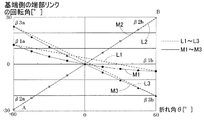
- the relationship between the arm rotation angle ⁇ and the bending angle ⁇ is represented by solid lines M1 to M3 in FIG.
- the arm rotation angles ⁇ at the respective bending angles ⁇ ( ⁇ 60 °, ⁇ 45 °, ⁇ 30 °,...) With the turning angle ⁇ fixed at 15 ° are plotted on the solid lines M1 to M3.
- the arm rotation angle ⁇ of all the arms is changed. While the path is a straight line (L1 to L3), the arm rotation angle ⁇ when the bending angle ⁇ is divided is determined by the path passing through the curves (M1 to M3).
- M1 to M3 the path passing through the curves
- an example of the posture change is given.
- the path of each arm rotation angle ⁇ is not always a straight line when the bending angle ⁇ is divided. This indicates that in order to change the link hub tip posture at a constant speed in the section from posture A to posture B, it is necessary to operate each arm rotation angle ⁇ non-linearly.
- the posture A to the posture B are divided into a plurality of sections, and the divided sections are continuously changed. Then, the moving speed from the position where the posture A points on the work surface to the position where the posture B points on the work surface is not constant.
- the object of the present invention is to solve the above-mentioned problems, and when the end effector performs work with the end effector using a link actuating device having three or more sets of four-bar linkage mechanisms, the end effector is substantially equal on the work surface. It is an object of the present invention to provide a control device and a control method for a link actuating device that can perform work while moving at high speed.
- the control device for a link operating device controls the next link operating device 1 as a control target.
- a distal end side link hub 15 is connected to a proximal end side link hub 14 via three or more sets of link mechanisms 11 to 13 so that the posture can be changed.
- 13 are proximal end and distal end side end link members 11a to 13a, 11b to 13b, one end of which is rotatably coupled to the proximal end side link hub 14 and the distal end side link hub 15, respectively.
- the end link members 11a to 13a and 11b to 13b on the end side and the other end of the end link members 11c to 13c are rotatably connected to the other ends of the end link members 11a to 13a, 11b to 13b.
- the geometric model in which the link mechanisms 11 to 13 are expressed by straight lines has a shape in which the base end side portion and the tip end side portion are symmetrical with respect to the center portion of the center link members 11c to 13c, By rotating the arms 11a to 13a, which are end link members on the base end side, to two or more sets of the link mechanisms 11 to 13 described above, the distal end side with respect to the link hub 14 on the base end side is rotated.
- the actuator 3 for arbitrarily changing the posture of the link hub 15 is provided, and the end effector 8 is installed on the link hub 15 on the distal end side.
- the control device 4 A divided section setting unit 42 divides a path from a start point to an end point on the work surface 60 on which the end effector 8 works, into a plurality of sections at the passing points, and sets the positions of the passing points.
- each of the sections in each section Arm rotation speed calculation means 43 for calculating the rotation speed at which the arms 11a, 12a, 13a rotate at a constant speed;
- Each actuator 3 is positioned so that each section is continuously rotated without acceleration / deceleration with the rotation speed of each arm 11a to 13a in each section as a value calculated by the rotation speed calculation means 43.
- Attitude change control means 41 for controlling; It has.
- the section to be divided is set based on the route on the work surface 60 on which the end effector 8 works.
- the arm rotation speed calculation means 43 moves the arms 11a, 12a, and 13a for each movement of each section so that the speed of movement on the work surface 60 of the end effector 8 becomes a constant target movement speed from the start point to the end point.
- the rotational speed (moving speed of ⁇ 1 axis, ⁇ 2 axis, ⁇ 3 axis) is calculated.
- the calculation of the rotation speed is performed from the specified target movement speed and the time of movement within each section determined from the distance of each section, and the rotation angle movement amount of each arm 11a, 12a, 13a in each section. .
- rotation speed (rotation angle movement amount) ⁇ (movement time).
- the target moving speed is a speed set by an operator.
- the posture change control means 41 sets the rotation speed of each of the arms 11a to 13a within each section to the calculated rotation speed, and accelerates / decelerates within each section at the set rotation speed.
- the actuators 3 are positioned and controlled so as to be continuously rotated without any.
- substantially constant speed means “approximately constant speed”, from the viewpoint of work by the end effector 8 except when the operation starts near the start point and when the operation ends near the end point. It means that the speed does not change to such an extent that it can be regarded as fast.
- the section setting in the divided section setting means 42 may be set by inputting each passing point from the command input means 40, or the divided section setting means 42 may determine and set each passing point by calculation. good.
- the work surface 60 may be a flat surface, a spherical surface, or another surface.
- the arm rotation speed calculation means calculates the rotation speed of each arm to each point which is one of the start point, end point, and each passing point. From the distance between any two points in the Cartesian coordinate system indicating the work surface 60 and the time obtained from the target moving speed, and the rotation angle movement amount of each arm between the two points, each arm in each section You may make it calculate the rotational speed of. Thereby, when the work surface 60 is in a plane, the rotation speed of each arm in each section can be accurately calculated.
- the arm rotation speed calculation means calculates the rotation speed of each arm to each point which is one of the start point, the end point, and each passing point. From the amount of movement between any two points obtained by the method and the time obtained from the target movement speed, and the rotation angle movement amount of each arm between the two points, the rotation speed of each arm in each section is calculated. You may make it calculate. Thereby, when the work surface 60 is a spherical surface, the rotational speed of each arm can be accurately and easily calculated.
- the values calculated before actual use of the link actuator 1 are stored for the position of each passing point in each section and the rotational speed of each arm 11a, 12a, 13a in each section.
- Section correspondence setting information storage means 46 is provided, and the posture change control means 41, in actual use, the position of each passing point stored in the section correspondence setting information storage means 46 and the arms 11a, 12a, The rotational speed of 13a may be read and controlled.
- the same operation may be repeated using the link actuator 1.
- the rotational speed of each arm 11a, 12a, 13a in each section is stored in advance in the section correspondence setting information storage means 46, and the posture change control means 41 reads the stored contents and performs control. In this way, it is not necessary to set the section and calculate the rotation speed every time, and the control can be performed quickly with a simple device. Even if the work is performed only once, it may be convenient to calculate and set the section and the arm rotation speed in advance.
- the divided section setting means 42 and the arm rotation speed calculation means 43 may be provided in a computer or the like different from the posture change control means 41.
- the above “in actual use” refers to when the end effector 8 actually performs processing or processing.
- the control method of the link actuating device of the present invention is a method of controlling the link actuating device 1 having the same configuration as the control device of the present invention, and is controlled as follows. That is, the control method of this link actuating device is: Dividing the path from the start point to the end point of movement of the end effector 8 on the work surface 60 on which the end effector 8 is working, into a plurality of sections at the passing points; Each arm in each section is determined from the movement time in each section determined from the designated target moving speed and the distance of each section, and the rotation angle movement amount of each arm 11a, 12a, 13a in each section.
- the end effector 8 can perform work while moving on the work surface 60 at a substantially constant speed, as described above for the control device of the present invention.
- the link operating device 1 includes a link operating device main body 2 and a plurality of posture control actuators 3 that operate the link operating device main body 2.
- the actuator 3 is controlled by the control device 4.
- the link actuator main body 2 is installed in a suspended state on the support member 5 via the spacer 6 on the base end side.
- the end effector 8 is mounted on the distal end side of the link actuator main body 2 via the distal end mounting member 7.
- the actuator 3 is a servo motor, for example, and has a position detector 35.
- the end effector 8 is, for example, a laser processing head, a dispenser, an inkjet nozzle, a welding torch, or the like, and performs an operation on the work surface 60 that is the surface of the workpiece W on the table device 50 (FIG. 2).
- the link actuator main body 2 has basically the same configuration as the link actuator 1 shown in FIG. For this reason, although a part is repeated, the structure of each part is demonstrated in detail. As shown in FIG. 3, the link actuator main body 2 includes three sets of link mechanisms 11, 12, and 13 (hereinafter referred to as “11 to 13”). In FIGS. 1 and 2, only one set is shown for the shape of the link mechanism 11, and in FIG. 1, the other two sets of link mechanisms 12 and 13 are indicated by two-dot chain rectangles for explaining the control. Yes.
- Each of the link mechanisms 11, 12, 13 includes a base end side link member 11a, 12a, 13a (hereinafter referred to as “11a-13a”) and a central link member 11c, 12c, 13c (hereinafter referred to as “11c— 13c “), and end link members 11b, 12b, 13b (hereinafter referred to as” 11b to 13b ”) on the distal end side to form a four-joint link mechanism comprising four rotating pairs. .
- the end link members 11a to 13a, 11b to 13b on the proximal end side and the distal end side are L-shaped, and one ends thereof are rotatably connected to the link hub 14 on the proximal end side and the link hub 15 on the distal end side, respectively.
- the central link members 11c to 13c are rotatably connected to the opposite ends of the end link members 11a to 13a and 11b to 13b on the proximal end side and the distal end side, respectively.
- the link hub 14 on the proximal end side and the link hub 15 on the distal end side have a hexagonal column shape, and the proximal side and the distal end side of the six side surfaces 16 apart from each other among the six side surfaces 16 constituting the outer peripheral surface are provided.
- the end link members 11a to 13a and 11b to 13b are rotatably connected to each other.
- the end link members 11a to 13a on the proximal end side constitute an arm and may be referred to as “arms 11a to 13a” in the following description.
- each of the link mechanisms 11 to 13 has a geometric model in which the end-side end link members 11a to 13a, the end-side end link members 11b to 13b, and the center link members 11c to 13c are represented by straight lines.
- the base end side portion and the tip end side portion are symmetrical with respect to the central portion of the link members 11c to 13c.
- the link actuating device main body 2 has a configuration in which two spherical link mechanisms are combined, and includes a base end side link hub 14 and base end side end link members 11a to 13a, a front end side link hub 15 and a front end side link hub 15.
- the rotation pair of the end link members 11b to 13b, and the central axis of each rotation pair of the end link members 11a to 13a, 11b to 13b and the central link members 11c to 13c on the base end side and the front end side are connected to the base end side.
- the spherical link centers PA and PB (FIGS. 1 and 2) intersect each other.
- the distance from the rotational pair of the members 11b to 13b and the spherical link center PB on the tip side is also the same.
- the distances from the rotation link pairs of the end link members 11a to 13a, 11b to 13b and the central link members 11c to 13c on the base end side and the tip end side and the spherical link centers PA and PB on the base end side and the tip end side are the same. It is.
- the central axis of the rotational pair of the proximal and distal end end link members 11a to 13a, 11b to 13b and the central link members 11c to 13c may have a certain crossing angle ⁇ or may be parallel. .
- the three sets of link mechanisms 11 to 13 have the same geometric shape.
- the geometrically identical shape is a geometric model in which each link member 11a to 13a, 11b to 13b, 11c to 13c is expressed by a straight line, that is, a model expressed by each rotating pair and a straight line connecting these rotating pairs.
- FIG. 4 is a diagram in which one link mechanism 11 is expressed by a straight line.
- the link mechanisms 11 to 13 of this embodiment are of a rotationally symmetric type, and include a base end side link hub 14 and a base end side end link member 11a to 13a, a front end side link hub 15 and a front end side end link member.
- the positional relationship between the central link members 11c to 13c is rotationally symmetric with respect to the center line C of the central link members 11c to 13c.
- FIG. 1 shows a state in which the central axis QA of the proximal-side link hub 14 and the central axis QB of the distal-side link hub 15 are on the same line
- FIG. 2 shows the central axis of the proximal-side link hub 14.
- FIG. 5 is a cross-sectional view showing a connecting portion between the link hub 14 on the base end side and the end link members 11a to 13a on the base end side.
- a shaft portion 18 protrudes from the side surface 16 of the proximal-side link hub 14, and inner rings (not shown) of double row bearings 17 are fitted on the shaft portion 18, so that the proximal-side end link members 11 a to 13 a
- An outer ring (not shown) of the bearing 17 is fitted into one end of the base end side of the link hub 14 side. That is, the inner ring is fixed to the link hub 14 on the base end side, and the outer ring rotates with the end link members 11a to 13a on the base end side.
- the bearing 17 is a ball bearing such as a deep groove ball bearing or an angular ball bearing, for example, and is fixed by applying a predetermined amount of preload by tightening with a nut 19.
- a roller bearing or a sliding bearing may be used in addition to the ball bearings arranged in a double row as in the illustrated example.
- the connecting portion between the link hub 15 on the distal end side and the end link members 11b to 13b on the distal end side has the same structure.
- the connecting portions of the end link members 11a to 13a and the central link members 11c to 13c on the base end side are also rotatably connected to each other via the double row bearings 20. That is, an outer ring (not shown) of the bearing 20 is fitted on the other end of the end link members 11a to 13a on the base end side, and an inner ring (not shown) of the bearing 20 is fitted to the shaft portion 21 provided on the central link members 11c to 13c. (Not shown) is fitted.
- the bearing 20 is, for example, a ball bearing such as a deep groove ball bearing or an angular ball bearing, and is fixed by applying a predetermined amount of preload by tightening with a nut 22.
- a roller bearing or a sliding bearing may be used in addition to the ball bearings arranged in a double row as in the illustrated example.
- the connecting portions of the end link members 11b to 13b and the central link members 11c to 13c on the front end side have the same structure.
- the central link members 11c to 13c and the proximal and distal ends of the central link members 11c to 13c with respect to the symmetry plane of the central link members 11c to 13c If the angular positional relationship between the partial link members 11a to 13a and 11b to 13b is the same between the proximal end side and the distal end side, the proximal end side link hub 14 and the proximal end side end link member are obtained from geometric symmetry.
- the distal end side link hub 15 and the distal end side end link members 11b to 13b move in the same manner, and the proximal end side and the distal end side have the same rotation angle and rotate at a constant speed.
- the plane of symmetry of the central link members 11c to 13c when rotating at a constant speed is referred to as a uniform speed bisector.
- the angles and lengths (the lengths from the spherical link centers PA and PB) of the shaft portions 18 of the end link members 11a to 13a and 11b to 13b on the proximal end side and the distal end side are equal to each other.
- the geometric shapes of the end link members 11a to 13a on the proximal end side and the 11b to 13b on the distal end side are equal.
- the shapes of the central link members 11c to 13c are the same on the proximal end side and the distal end side.
- the connecting portions with the end link members 11b to 13b and the two connecting portions of the end link members 11a to 13a, 11b to 13b on the base end side and the distal end side and the central link members 11c to 13c have a bearing structure. ing. As a result, it is possible to reduce the rotational resistance by suppressing the frictional resistance at the connecting portion, and to ensure smooth power transmission and improve the durability.
- the movable range of the link hub 15 on the distal end side with respect to the link hub 14 on the proximal end side can be widened.
- the maximum value (maximum folding angle) of the folding angle ⁇ between the central axis QA of the link hub 14 on the proximal end side and the central axis QB of the link hub 15 on the distal end side can be set to about ⁇ 90 °.
- the turning angle ⁇ of the distal end side link hub 15 relative to the proximal end side link hub 14 can be set in a range of 0 ° to 360 °.
- the plurality of actuators 3 are installed on the support member 5 at equal intervals in the circumferential direction.
- the number of actuators 3 is three, which is the same number as the link mechanisms 11, 12, and 13. However, even if the number of actuators 3 is two, the operation of the link actuator main body 2 can be defined.
- the actuator 3 comprises a motor, and a pinion 30 is provided on the output shaft 3a.
- a connecting member 31 (FIG. 5) is fixedly attached to a rotating pair of the end link members 11 a to 13 a on the end side with the shaft portion 18, and the sector gear 32 meshing with the pinion 30 is attached to the connecting member 31. Is provided.
- the central axis of the sector gear 32 coincides with the central axis of the shaft portion 18 (FIG. 5).
- the pinion 30 and the sector gear 32 constitute a speed reducer 33.
- each actuator 3 When each actuator 3 is driven to rotate, the rotation is transmitted to the shaft portion 18 (FIG. 5) via the speed reduction mechanism 33, and the arms 11a to 11b, which are proximal end link members with respect to the proximal link hub 14, are provided.
- the angle of 13a is changed. Thereby, the attitude of the link hub 15 on the distal end side with respect to the link hub 14 on the proximal end side is determined.
- This posture is defined by the bending angle ⁇ (FIG. 3) and the turning angle ⁇ (FIG. 3).
- the rotation angles ⁇ 1, ⁇ 2, and ⁇ 3 of the arms 11a to 13a are calculated from the values detected by the rotation angle detection means 35 and the speed reduction ratio of the speed reduction mechanism 33.
- the control device 4 changes the posture of the distal end side link hub 15 with respect to the proximal end side link hub 14 from the start point posture to the end point posture, and at this time, the work point is the command input means 40 on the work surface 60.
- This is a device that controls each actuator 3 so that it moves at the target moving speed V set in step 1 and changes its posture.
- a work point is a point used as the front-end
- the starting point posture is the current posture, and the starting point of each arm 11a to 13a is the current position of each arm 11a to 13a.
- the start point is the end point at the time of the previous movement, but even if it is the current position calculated from the value detected by each rotation angle detection means 35 and the speed reduction ratio of the speed reduction mechanism 33, it is determined.
- the designated reference position may be used.
- the starting point posture may be given from an external command input means 40 for the control device 4.
- the command input means 40 is a device that performs input by an operator's operation such as a keyboard and a mouse, a higher-level control device for the control device 4, a communication means for obtaining information from external information devices, a storage It may be a medium drive means.
- the control device 4 is of a numerical control type by a computer, and includes a divided section setting means 42, an arm rotation speed calculation means 43, a section corresponding setting information storage means 46, and an attitude change control means 41.
- the division section setting means 42 divides the path from the start point to the end point on which the end effector 8 moves on the work surface 60 on which the end effector 8 works into a plurality of sections or a plurality of sections at one passage point, and the position of the passage point. Set.
- the route from the start point to the end point on the work surface 60 is input by the orthogonal coordinates from the command input means 40, and each passing point is also indicated by the orthogonal coordinates in the divided section setting means 42.
- the division number of the section is set so that the moving speed of the end effector 8 on the work surface 60 is substantially constant.
- the process of dividing the route into a plurality of sections at the passing points may be input by an operator from the command input means 40, or may be automatically divided by providing the divided section setting means 42 with a dividing function. good.
- the divided section setting means 42 is simply a means for storing the coordinates of the start point, the end point, and the passing point.
- the divided section setting means 42 When the divided section setting means 42 is configured to calculate each passing point and set the division, the route from the start point to the end point is equally divided, for example, by a predetermined number of divisions according to a predetermined rule, and the arm rotation speed is calculated.
- the means 43 is caused to calculate the rotational speed, and it is determined whether or not control (constant speed control) can be performed so that the speed from the start point to the end point is substantially constant. If constant speed control is not possible, change the number of divisions and repeat the process of causing the arm rotational speed calculation means 43 to calculate the rotational speed again, and determine the classification by the process for determining that constant speed control is possible. good.
- the arm rotation speed calculation means 43 is the time of movement within each section determined from the target movement speed specified by the operator from the command input means 40 and the distance of each section, and each arm 11a, 12a, The rotational speed at which each arm 11a, 12a, 13a rotates at a constant speed in each section is calculated from the rotational angle movement amount of 13a.
- the section correspondence setting information storage means 46 is, for each section, the position of a point that is a start point, a passing point, or an end point corresponding to each section in each arm 11a, 12a, 13a calculated by the arm rotation speed calculation means 43; The arm rotation speed is stored.
- the posture change control means 41 sets the rotation speed of each arm 11a to 13a in each section to the value calculated by the rotation speed calculation means 43, and continuously rotates each section without acceleration / deceleration. Positioning control of each actuator 3 is performed.
- the posture change control means 41 includes a command reading unit 51, a synchronization control unit 52, and the same number of individual control units 53 as the actuator 3.
- the command reading unit 51 reads the position of each point and the arm rotation speed for each section of each arm 11a, 12a, 13a stored in the section correspondence setting information storage means 46. Instead of reading from the section correspondence setting information storage means 46, the command reading unit 51 reads the position of each point and the arm rotation speed for each section of each arm 11a, 12a, 13a from the arm rotation speed calculation means 43. good.
- the synchronization control unit 52 is a unit that causes each individual control unit 53 to perform synchronization control so that the arms 11a to 13a start rotating from the start point at the same time and stop at the end point at the same time.
- Each individual control unit 53 controls the position of the corresponding actuator 3 from a given point to point.
- the individual control unit 53 is, for example, an operation amount conversion unit (not shown) that converts an arm rotation angle into an actuator movement amount, an operation command generation unit (not shown), and a servo controller unit (not shown). It consists of.
- the operation command generation unit gives an operation command to the servo controller unit by pulse delivery or the like according to the trapezoidal speed control speed curve.
- the servo controller unit performs feedback control using the given operation command and the detected value of the rotation angle detecting means 35.
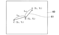
- FIG. 6 shows arbitrary three points (A, B, C) on the work surface 60 on which the end effector 8 works.
- Three points (A, B, C) are points indicated by XY orthogonal coordinates. If the distance between points A and B is Lab, and the distance between points B and C is Lbc, then Lab and Lbc are as follows.
- posture A ( ⁇ a, ⁇ a), posture B ( ⁇ b, ⁇ b), and posture C ( ⁇ c, ⁇ c)
- postures A, B Each arm rotation angle corresponding to C is calculated from the above formula (1) of the link hub and the arm rotation angle, respectively, rotation angle A ( ⁇ 1a, ⁇ 2a, ⁇ 3a), rotation angle B ( ⁇ 1b, ⁇ 2b, ⁇ 3b), rotation angle.
- the relationship is established as C ( ⁇ 1c, ⁇ 2c, ⁇ 3c).
- the rotation angle movement amounts of the ⁇ 1, ⁇ 2, and ⁇ 3 axes when moving from point A to B are ⁇ 1ab, ⁇ 2ab, and ⁇ 3ab
- the movement speeds V1ab, V2ab, and V3ab that are the rotation speeds of the respective axes are expressed by the following equations. It can be expressed as Note that the movements of the ⁇ 1, ⁇ 2, and ⁇ 3 axes mean rotations about the rotation centers of the arms 11a to 13a, respectively.
- the arm rotation speed calculation means 43 is connected to the ⁇ 1 axis, ⁇ 2 axis, ⁇ 3.
- Each movement amount of the shaft and the speed obtained from the above formula are set for each section, and continuous positioning control is performed without acceleration / deceleration in each section. Note that “continuous positioning without acceleration / deceleration” means that rotation is continued without stopping.
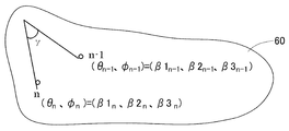
- Figure 7 shows generalization.
- the orthogonal coordinate of the n-th point is (Xn, Yn), and n ⁇
- the orthogonal coordinates of the first point are (Xn-1, Yn-1)
- the movement amounts of the ⁇ 1, ⁇ 2, and ⁇ 3 axes from the (n ⁇ 1) th point to the nth point are ⁇ 1, ⁇ 2, and ⁇ 3,
- the movement speeds V1n, V2n, and V3n of each axis when moving to the Nth point can be expressed by the following equations.
- the arm rotation speed calculation means 43 calculates the movement time T of each section and the movement speeds V1n, V2n, V3n of the respective axes, which are the rotation speeds of the arms in each section, according to the equations (2) to (5). To do.
- the arm rotation speed calculation means 43 has a command conversion unit 44. Prior to the calculation based on the above equations (2) to (5), the command conversion unit 44 sets the coordinate position of each point indicated by the orthogonal coordinates on the work surface 60 according to the above equation (1). By converting the rotation of the arms 11a to 11c, the movement amounts ⁇ 1, ⁇ 2, and ⁇ 3 of the respective axes are obtained.
- the movement of the end effector 8 from the start point to the end point that is, the movement of the link hub 15 on the distal end side from the start point posture A ( ⁇ a, ⁇ a) to the end point posture B ( ⁇ b, ⁇ b).
- the divided section setting means 42 divides and sets a plurality of sections, the section to be divided is set based on the route on the work surface 60 on which the end effector 8 works.
- the arm rotation speed calculation means 43 is used for each arm 11a, 12a, 13a, etc. for each movement of each section so that the speed of movement on the work surface of the end effector 8 becomes a constant target movement speed V from the start point to the end point.
- a rotational speed (moving speed of ⁇ 1, ⁇ 2, and ⁇ 3 axes) is calculated. This rotation speed is calculated from the movement time in each section determined from the designated target moving speed V and the distance of each section, and the rotation angle movement amount of each arm 11a, 12a, 13a in each section.
- the posture change control means 41 sets the rotation speed of each arm 11a to 13a in each section to the rotation speed calculated by the arm rotation speed calculation means 43, and the inside of each section is set with this set rotation speed.
- Each actuator 3 is positioned and controlled so as to be continuously rotated without acceleration / deceleration.
- Second Embodiment A second embodiment of the present invention will be described with reference to FIG.
- the second embodiment is the same as the first embodiment except for the matters described in particular.
- the functions of the divided section setting means 42, the arm rotation speed calculation speed calculation means 43, and the section correspondence setting information storage means 46 in FIG. 1 are partially different from those of the first embodiment. is there.
- the section correspondence setting information storage means 46 is different from the first embodiment in the value stored.
- the constant speed movement is shown when the work surface 60 of the end effector 8 is a plane.
- the work surface 60 is a spherical surface, this spherical work surface is used.
- the movement of the tip of the end effector 8 on 60 can be made constant speed. This makes the operation of the link hub 15 on the distal end side uniform.
- the movement speed of each axis ( ⁇ 1, ⁇ 2, and ⁇ 3 axes) when the operation of the link hub 15 on the distal end side is made constant speed is shown.
- the posture (fold angle, turning angle) of the distal link hub 15 at two points (n ⁇ 1) and n is defined as posture A ( ⁇ n ⁇ 1, ⁇ n ⁇ 1), posture B ( ⁇ N, ⁇ n).
- the arm rotation angles corresponding to the postures A and B are related as the rotation angle A ( ⁇ 1n ⁇ 1, ⁇ 2n ⁇ 1, ⁇ 3n ⁇ 1) and the rotation angle B ( ⁇ 1n, ⁇ 2n, ⁇ 3n), respectively, from the above equation (1). Holds.
- the rotational angle movement amount ⁇ (rad) when moving from the posture A ( ⁇ n ⁇ 1, ⁇ n ⁇ 1) to the posture B ( ⁇ n, ⁇ n) can be approximated by the following equation from the spherical trigonometry.
- Each movement amount of ⁇ 1, ⁇ 2, and ⁇ 3 axes and the speed obtained from the above formula are set for each section, that is, for each point, and each point is continuously positioned without acceleration / deceleration.
- the divided section setting means 42 in FIG. 1 divides the path from the start point to the end point on which the end effector 8 on the work surface 60 made of a spherical surface moves into a plurality of sections at the passing points. That is, the above points are determined.
- the arm rotation speed calculation means 43 is based on the designated target moving speed V and the movement time T in each section determined from the distance of each section, and the rotation angle movement amount ⁇ of each arm 11a, 12a, 13a in each section. Based on the above equations (6) to (8), the rotational speeds V1n, V2n, and V3n are calculated.
- the rotation speeds V1n, V2n, and V3n are movement speeds of rotation angles at which the arms 11a, 12a, and 13a rotate at a constant speed in each section.
- the posture change control means 41 sets the rotation speeds V1n, V2n, V3n of the arms 11a, 12a, 13a in the intervals between the points to the values calculated by the rotation speed calculation means 43, and adds each interval. Positioning control of each actuator 3 is performed so as to continuously rotate without deceleration.
- the end effector 8 can work while moving on the work surface 60 at a substantially constant speed.
- a third embodiment of the invention will be described.
- the speed of the relative movement is constant. It is.
- the table device 50 is an XY table whose table surface moves in two orthogonal axes.
- the target work W whose surface is the work surface 60 is moved.
- the link operating device 1 may be mounted on the table device 50, the link operating device 1 may be moved, and the work W may be fixed in position.
- the third embodiment is the same as the first embodiment except for the items to be specifically described.
- the third embodiment is partially different from the first embodiment in the functions of the divided section setting means 42, the arm rotation speed calculation speed calculation means 43, and the section correspondence setting information storage means 46 in FIG.
- the section correspondence setting information storage means 46 is different from the first embodiment in the value stored.
- the position of the target workpiece W on the link actuator 1 and the work surface 60 is fixed.
- the target workpiece W is set to an XY table, That is, a configuration in which the table movable surface is mounted on a table device that can move in two orthogonal axes or the link operating device 1 is mounted on an XY table is common.
- the table is used in combination with the three axes ( ⁇ 1, ⁇ 2, ⁇ 3) of the link actuating device 1 and the two axes (X, Y) of the table device 50 (FIG. 2) composed of an XY table.
- a combined speed (moving speed) Vn when the end effector 8 moves each point on the planar work plane 60 at a specified speed V at a constant speed will be described.
- the orthogonal coordinates of the target workpiece W are (Xn, Yn) at the nth point and (Xn-1, Yn-1) at the n-1th point.
- the movement speeds V1n, V2n, V3n, Vxn, and Vyn of each axis can be expressed by the following equations.
- the moving speeds of the ⁇ 1 axis, ⁇ 2 axis, and ⁇ 3 axis are moving speeds of rotation angles.
- the arm rotation speed calculating means 43 is connected to the ⁇ 1 axis, ⁇ 2 axis, ⁇ 3 axis, X axis, Y
- Each movement amount of the shaft and the speed obtained from the above formula are set for each section, that is, for each point, and each point is continuously positioned and controlled without acceleration / deceleration.
- the divided section setting means 42 in FIG. 1 has a plurality of passing points from the start point to the end point of the relative movement of the end effector 8 on the work surface 60 that is a plane relatively moving in the XY directions. Is divided into sections. That is, the above points are determined.
- the arm rotation speed calculation means 43 moves the movement time T in each section determined from the designated target movement speed V and the distance of each section, and the rotation angle movement amounts ⁇ 1, ⁇ 2 of the arms 11a, 12a, 13a in each section. , ⁇ 3, and the rotational speeds V1n, V2n, and V3n are calculated based on the above formulas (9) to (11) and (14).
- the rotation speeds V1n, V2n, and V3n are movement speeds of rotation angles at which the arms 11a, 12a, and 13a rotate at a constant speed in each section.
- the arm rotation speed calculation means 43 has a configuration in which, in addition to the rotation speed of each axis, a function for calculating the movement speeds Vxn and Vyn of the X axis and the Y axis by the above formulas (12), (13), and (14) is added. It is also good.
- the posture change control means 41 sets the rotation speeds V1n, V2n, V3n of each arm 8 in each section between points to the values calculated by the rotation speed calculation means 43, and continues each section without acceleration / deceleration. Then, each actuator 3 is positioned and controlled to rotate.
- the X-axis and Y-axis control means (not shown) sets the X-axis and Y-axis moving speeds Vxn and Vyn calculated based on the above formulas (12) and (13), and sets the table device at those speeds. 50 axes are moved.
- the end effector 8 works while moving on the work surface 60 at a substantially constant speed in consideration of the relative movement. Can be controlled.
- the control device 4 sets the position of each passing point (each section) and calculates the arm rotation speed in each section in actual use.
- the values calculated before actual use of the link actuator 1 for the positions of these passing points and the rotational speeds of the arms 11a, 12a, 13a in each section are stored in the section corresponding setting information storage means 46.
- the posture change control means 41 reads and controls the position of each passing point stored in the section correspondence setting information storage means 46 and the rotation speed of each arm 11a, 12a, 13a. You may do it.
- a device for setting / calculating the position of each passing point and the rotational speed of each arm 11a, 12a, 13a in each section before actual use is different from the control device 4 having the posture change control means 41.
- the computer may be provided.
- the same operation may be repeated using the link actuator 1.
- the rotation speed of each arm 11a, 12a, 13a in each section is stored in advance in the section correspondence setting information storage means 46, and the posture change control means 41 reads out the stored contents and performs control.
- the control can be performed easily and quickly. Even if the work is performed only once, it may be convenient to calculate and set the section and the arm rotation speed in advance.
- the above “in actual use” refers to the time when the end effector 8 actually performs processing or processing except for the trial operation.
- the present invention is not limited to the above embodiment, and various additions, changes, or deletions are possible without departing from the gist of the present invention. Therefore, such a thing is also included in the scope of the present invention.
Abstract
リンク作動装置(1)は、複数のリンク機構(11~13)の基端側のリンクである各アーム(11a~13a)をアクチュエータ(3)の駆動で回転させることで、先端側のリンクハブ(15)の姿勢が変更する。制御装置(4)は、エンドエフェクタ(8)が作業する被作業面(60)上の経路を通過点で複数の区間に分割して設定する手段(42)を設ける。目標移動速度および各区間の距離から定まる各区間内の移動の時間と、各区間における各アームの回転角移動量とから、前記各区間における前記各アームが等速回転する回転速度を計算する手段(43)を設ける。この回転速度で加減速無しで連続して回転させるように各アクチュエータ(3)を位置決め制御する手段(41)を設ける。
Description
この出願は、2014年2月20日出願の特願2014-030425の優先権を主張するものであり、その全体を参照により本願の一部をなすものとして引用する。
この発明は、産業機器等の精密で広範な作動範囲を必要とする機器に用いられるリンク作動装置の制御装置および制御方法に関する。
三次元空間における複雑な加工や処理等の作業を高速かつ精密に行うリンク作動装置として、4節連鎖のリンク機構を3組以上有し、2自由度の動作を可能とした装置がある(例えば、特許文献1~3)。これらのリンク作動装置は、例えば図9に示すように、基端側のリンクハブ14と、先端側のリンクハブ15と、これらリンクハブ14,15を互いに連結する3組のリンク機構11,12,13とでなる。各リンク機構11,12,13は、基端側の端部リンク部材11a,12a,13a、先端側の端部リンク部材11b,12b,13b、および中央リンク部材11c,12c,13cで構成されている。なお、図9では、基端側の端部リンク部材13aは図示されていないが、区別のために符号を用いて説明する。また、前記基端側の端部リンク部材11a,12a,13aを、以下、アーム11a,12a,13aと称する。
この種のリンク作動装置は、3組以上のリンク機構11,12,13を2個以上のモータのようなアクチュエータ(図示せず)により駆動することで、基端側のリンクハブ14に対する先端側のリンクハブ15の姿勢(以下「リンクハブ先端姿勢」または単に「姿勢」と称す)を変更する。リンクハブ先端姿勢は、折れ角θと旋回角φにより決定される。折れ角θは、基端側のリンクハブ14の中心軸QAに対する先端側のリンクハブ15の中心軸QBの傾斜角度であり、旋回角φは、基端側のリンクハブ14の中心軸QAに対する先端側のリンクハブ15の中心軸QBの旋回角度である。
リンクハブ先端姿勢の制御は、具体的には、前記折れ角θおよび旋回角φから、各アーム11a,12a,13aの回転角β1n,β2n,β3nを求め、アーム11a,12a,13aを駆動するアクチュエータに位置決めさせる。なお、以下の説明において、アームの回転角を「アーム回転角」と称す。例えば、図10に示すある姿勢A(θa,φa)と異なる姿勢B(θb,φb)について、各々の姿勢A,Bに対応する各アーム回転角は、下記の折れ角θおよび旋回角φとアーム回転角βとの関係を示す式(1)により、A(β1a,β2a,β3a)、B(β1b,β2b,β3b)として求められる。
cos(θ/2)sinβn-sin(θ/2)sin(φ+δn)cosβn+sin(γ/2)=0…式(1)
γは、アーム11a,12a,13aに回転自在に連結された中央リンク部材11c,12c,13cの連結端軸と、先端側の端部リンク部材11b,12b,13bに回転自在に連結された中央リンク部材11c,12c,13cの連結端軸とが成す角度である。δn(δ1,δ2,δ3)(図示せず)は、基準となるアーム11aに対する各基端側の端部リンク部材11a,12a,13aの円周方向の離間角である。リンク機構11,12,13の数が3組で、各リンク機構11,12,13が円周方向に等配である場合、各アーム11a,12a,13aの離間角δ1,δ2,δ3はそれぞれ0°,120°,240°となる。
γは、アーム11a,12a,13aに回転自在に連結された中央リンク部材11c,12c,13cの連結端軸と、先端側の端部リンク部材11b,12b,13bに回転自在に連結された中央リンク部材11c,12c,13cの連結端軸とが成す角度である。δn(δ1,δ2,δ3)(図示せず)は、基準となるアーム11aに対する各基端側の端部リンク部材11a,12a,13aの円周方向の離間角である。リンク機構11,12,13の数が3組で、各リンク機構11,12,13が円周方向に等配である場合、各アーム11a,12a,13aの離間角δ1,δ2,δ3はそれぞれ0°,120°,240°となる。
ここで、姿勢Aから姿勢Bへの姿勢変更は、各アーム11a,12a,13aの回転角がβ1aからβ1b、β2aからβ2b、β3aからβ3bへそれぞれ変化することで実現される。
また、特許文献4では、基端側のリンクハブ14の中心軸QAの延長上に設定された基端側のリンクハブ14の中心軸QAと垂直な直交座標から、最小自乗法による収束演算を用いてリンクハブの姿勢(折れ角θ、旋回角φ)を取得している。これにより、エンドエフェクタが作業する被作業面(直交座標平面)の任意の座標への位置決めが可能となる。
リンクハブ先端姿勢につき姿勢A(θa、φa)から姿勢B(θb、φb)への姿勢変更量が大きい場合、姿勢Aから姿勢Bまで単にポイントツーポイント(Point-to-Point)制御で同期して等速運動で制御すると、特に姿勢Aと姿勢B間の経路の中間部付近において、ポイントツーポイント制御で決定されるアーム回転角βが、前記式(1)から定まるアーム回転角βと比べて大きく異なる位置に位置決め指令される。そのため、各アーム11a,12a,13a間に干渉が生じ、リンク機構11,12,13の駆動に過大なトルクが必要になる。
そこで、姿勢Aから姿勢Bの間を複数の姿勢に分割し、分割された各区間をポイントツーポイント制御で姿勢変更することで、姿勢変更量が大きい場合でもリンク作動装置の各部に過大な負荷をかけずに駆動できるようにした制御装置が提案されている。例えば、旋回角φを15°に固定した状態で折れ角θを-60°から60°に姿勢変更する際、A,B間を移動するリンクハブ先端姿勢の経路が最短となるようにA,B間の折れ角θを分割する。
具体例を示すと、旋回角を15°に固定した状態で、折れ角θを-60°から60°に姿勢変更する際、A,B間を移動するリンクハブ先端姿勢の経路が最短となるように折れ角θを分割した場合、アーム回転角βと折れ角θの関係が、前記式(1)より、図11の実線M1~M3で表わされる。旋回角φを15°に固定した状態での、各折れ角θ(-60°,-45°,-30°,…)における各アーム回転角βが実線M1~M3上にプロットされている。
一方、旋回角φを15°に固定した状態で折れ角θを-60°から60°に一気にポイントツーポイント制御で姿勢変更する場合のアーム回転角βと折れ角θの関係は、図11の点線L1~L3で表わされている。
つまり、旋回角φを15°に固定した状態で折れ角θを-60°から60°に姿勢変更する例において、ポイントツーポイント制御で姿勢変更する場合は、全てのアームにつきアーム回転角βの経路が直線(L1~L3)になるのに対し、折れ角θを分割した場合のアーム回転角βは、曲線(M1~M3)を通過する経路で各姿勢が決まる。ここでは、姿勢変更の一例を挙げたが、全ての姿勢変更において、折れ角θを分割した場合に各アーム回転角βの経路が直線になるとは限らない。これは、姿勢Aから姿勢Bの区間において、リンクハブ先端姿勢を等速で変化させるためには、各アーム回転角βを非線形に動作させる必要があることを示している。
例えば、先端側のリンクハブ15に設置されたエンドエフェクタの被作業面を球面とした場合において、姿勢Aから姿勢Bまでを複数の区間に分割し、分割された各区間を連続的に変化させると、姿勢Aが被作業面上に指す位置から姿勢Bが被作業面上に指す位置までの移動速度は一定にならない。
したがって、図9、図10に示す4節連鎖のリンク機構を3組以上有するリンク作動装置を用いて、レーザによる加工や、ディスペンサ、インクジェットによる塗布、または溶接等を行う場合、被作業面上でエンドエフェクタが不等速動作を行うと、加工ムラや塗装ムラ、および溶接の際の肉厚ムラ等が発生する。
この発明の目的は、上記課題を解消し、4節連鎖のリンク機構を3組以上有するリンク作動装置を用いてエンドエフェクタで作業を行うときに、エンドエフェクタが被作業面上を実質的に等速で移動しながら作業を行うことができるリンク作動装置の制御装置および制御方法を提供することである。
この発明のリンク作動装置の制御装置を実施形態に用いた符号を付して説明する。この発明のリンク作動装置の制御装置4は、次のリンク作動装置1を制御対象とする。このリンク作動装置1は、基端側のリンクハブ14に対し先端側のリンクハブ15を、3組以上のリンク機構11~13を介して姿勢を変更可能に連結し、前記各リンク機構11~13は、それぞれ前記基端側のリンクハブ14および先端側のリンクハブ15に一端が回転可能に連結された基端側および先端側の端部リンク部材11a~13a,11b~13bと、これら基端側および先端側の端部リンク部材11a~13a,11b~13bの他端に両端がそれぞれ回転可能に連結された中央リンク部材11c~13cとでなり、前記各リンク機構11~13は、このリンク機構11~13を直線で表現した幾何学モデルが、前記中央リンク部材11c~13cの中央部に対する基端側部分と先端側部分とが対称を成す形状であり、前記3組以上のリンク機構11~13のうち2組以上のリンク機構に、前記基端側の端部リンク部材であるアーム11a~13aを回転させることにより、前記基端側のリンクハブ14に対する前記先端側のリンクハブ15の姿勢を任意に変更させるアクチュエータ3を設け、前記先端側のリンクハブ15にエンドエフェクタ8を設置してなる。
前記制御装置4は、
前記エンドエフェクタ8が作業する被作業面60上の前記エンドエフェクタ8が移動する始点から終点までの経路を通過点で複数の区間に分割し、前記通過点の位置を設定する分割区間設定手段42と、
指定された目標移動速度Vおよび前記各区間の距離から定まる各区間内の移動の時間と、前記各区間における前記各アーム11a,12a、13aの回転角移動量とから、前記各区間における前記各アーム11a,12a,13aが等速回転する回転速度を計算するアーム回転速度計算手段43と、
前記各区間内での前記各アーム11a~13aの回転速度を前記回転速度計算手段43で計算された値として、前記各区間を加減速無しで連続して回転させるように前記各アクチュエータ3を位置決め制御する姿勢変更制御手段41と、
を備えている。
この構成によると、エンドエフェクタ8の始点から終点までの移動、つまり先端側のリンクハブ15の始点姿勢A(θa、φa)から終点姿勢B(θb、φb)への移動において、分割区間設定手段42に区間を複数に分割して設定する際に、分割する区間はエンドエフェクタ8が作業する被作業面60上での経路を基準に区間設定される。
アーム回転速度計算手段43は、エンドエフェクタ8の被作業面60上を移動する速度が始点から終点まで一定の前記目標移動速度となるように、各区間の移動ごとに各アーム11a,12a,13aの等速回転する回転速度(β1軸、β2軸、β3軸の移動速度)を計算する。この回転速度の計算は、指定された目標移動速度および前記各区間の距離から定まる各区間内の移動の時間と、前記各区間における前記各アーム11a,12a,13aの回転角移動量とから行う。例えば、回転速度=(回転角移動量)÷(移動時間)とする。前記目標移動速度はオペレータが設定する速度である。
姿勢変更制御手段41は、前記各区間内での前記各アーム11a~13aの回転速度を、前記の計算された回転速度に設定し、この設定された回転速度で、前記各区間内を加減速無しで連続して回転させるように前記各アクチュエータ3を位置決め制御する。
これにより、エンドエフェクタが作業する被作業平面(直交座標)上の複数点を実質的に等速で動作することが可能となる。すなわち、始点から終点への位置決め制御が、途中の被作業面60上の任意の点を加減速無しで通過することになる。そのため、エンドエフェクタとして、例えばレーザ加工ヘッド、ディスペンサ、インクジェットノズル、溶接器具等をリンクに付加した際、レーザの加工ムラやディスペンサ、インクジェットによる塗布ムラ、溶接による溶接ムラをなくすことができる。
なお、区間の分割数は、エンドエフェクタ8の被作業面60上を移動する速度が実質的に等速となるように設定する。「実質的に等速」とは、換言すれば「近似的に等速」であり、始点付近での動作開始時と終点付近での動作終了時を除き、エンドエフェクタ8による作業の観点から等速であると見なせる程度に速度の変化が生じないことを言う。
分割区間設定手段42における区間の設定は、指令入力手段40から各通過点を入力することで設定しても、また分割区間設定手段42が各通過点を計算により求めて設定するようにしても良い。
また、アーム11a~13aに着目すると、ある区間のアーム回転速度と、次の区間のアーム回転速度とでは差が生じ、区間の隣り合う箇所でアーム回転の加減速が生じるが、被作業面60でのエンドエフェクタ8の移動は、前記アーム11a~13aの加減速が無視できる程度の近似的な等速になる。
前記被作業面60は、平面であっても、球面であっても、またその他の面であっても良い。前記被作業面60が平面である場合は、前記アーム回転速度計算手段は、前記始点、終点、および各通過点のいずれかの点である各ポイントへの前記各アームの回転速度を、前記被作業面60を示す直交座標系の任意の2ポイント間の距離と前記目標移動速度から求められる時間と、前記2ポイント間の前記各アームの回転角移動量とから、前記各区間における前記各アームの回転速度を計算するようにしても良い。これにより、被作業面60が平面にある場合に、前記各区間における前記各アームの回転速度を的確に計算できる。
前記被作業面60が球面である場合は、前記アーム回転速度計算手段は、前記始点、終点、および各通過点のいずれかの点である各ポイントへの前記各アームの回転速度を、球面三角法より得られる任意の2ポイント間の移動量と前記目標移動速度から求められる時間と、前記2ポイント間の前記各アームの回転角移動量とから、前記各区間における前記各アームの回転速度を計算するようにしても良い。これにより、被作業面60が球面である場合に、前記各アームの回転速度を正確にかつ簡単に計算できる。
この発明において、前記各区間における、前記各通過点の位置と、前記各区間における前記各アーム11a,12a,13aの回転速度につき、リンク作動装置1の実使用の前に計算した値を記憶する区間対応設定情報記憶手段46を設け、前記姿勢変更制御手段41は、実使用時は、前記区間対応設定情報記憶手段46に記憶された前記各通過点の位置と、前記各アーム11a,12a,13aの回転速度を読み出して制御するようにしても良い。
リンク作動装置1を用いて同じ作業を繰り返して行う場合がある。そのような場合、各区間における前記各アーム11a,12a,13aの回転速度を予め区間対応設定情報記憶手段46に記憶させておき、前記姿勢変更制御手段41はその記憶内容を読み出して制御を行うようにすれば、区間の設定や回転速度の計算を毎回行う必要がなく、制御が簡単な装置で迅速に行える。一度だけの作業であっても、予め区間およびアーム回転速度を予め計算して設定しておくことが便利な場合がある。
なお、この構成の場合、分割区間設定手段42およびアーム回転速度計算手段43は、姿勢変更制御手段41とは互いに別のコンピュータ等に設けられていても良い。また、上記の「実使用時」とは、実際にエンドエフェクタ8で加工や処理を行うときを言う。
この発明のリンク作動装置の制御方法は、この発明の制御装置と同じ構成のリンク作動装置1を制御する方法であり、次のように制御する。すなわち、このリンク作動装置の制御方法は、
前記エンドエフェクタ8が作業する被作業面60上の前記エンドエフェクタ8が移動する始点から終点までの経路を通過点で複数の区間に分割し、
指定された目標移動速度および前記各区間の距離から定まる各区間内の移動の時間と、前記各区間における前記各アーム11a,12a,13aの回転角移動量とから、前記各区間における前記各アーム11a,11b12a,11c13aの回転速度を計算し、
前記各区間内での前記各アームの回転速度を前記の計算された値として、前記各区間を加減速無しで連続して回転させるように前記各アクチュエータ8を位置決め制御することで、
前記作業面60上の分割された複数点間を始点から終点まで実質的に一定速度に動作させる方法である。
この制御方法によると、この発明の制御装置につき前述したと同様に、エンドエフェクタ8が被作業面60上を実質的に等速で移動しながら作業を行うことができる。
請求の範囲および/または明細書および/または図面に開示された少なくとも2つの構成のどのような組合せも、本発明に含まれる。特に、請求の範囲の各請求項の2つ以上のどのような組合せも、本発明に含まれる。
本発明は、添付の図面を参考にした以下の好適な実施形態の説明からより明瞭に理解されるであろう。しかしながら、実施形態および図面は単なる図示および説明のためのものであり、本発明の範囲を定めるために利用されるべきものではない。本発明の範囲は添付の請求の範囲によって定まる。添付図面において、複数の図面における同一の部品番号は、同一または相当部分を示す。
この発明の第1実施形態に係るリンク作動装置の制御装置のブロック図とその制御対象となるリンク作動装置の一部省略正面図とを組み合わせた説明図である。
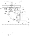
同リンク作動装置の図1と異なる動作状態を示す一部省略正面図である。
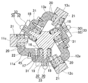
同リンク作動装置のリンク作動装置本体の斜視図である。
同リンク作動装置のリンク機構の一つを直線で表現した幾何学的モデル図である。
同リンク作動装置の基端側のリンクハブ、基端側の端部リンク部材、および中央リンク部材の断面図である。
同リンク作動装置に搭載されたエンドエフェクトが作業する平面からなる被作業面上の移動経路の簡易化例を表す直交座標系の図である。
同リンク作動装置に搭載されたエンドエフェクトが作業する平面からなる被作業面上の移動経路の一般化例を表す直交座標系の図である。
同リンク作動装置に搭載されたエンドエフェクトが作業する球面からなる被作業面上の移動経路の例を表す曲座標系の図である。
従来の4節連鎖のリンク機構を3組以上設けたリンク作動装置の一例の斜視図である。
同リンク作動装置の姿勢変更動作の説明図である。
同リンク作動装置を姿勢変更する場合の折れ角と基端側の端部リンクの回転角との関係を示す図である。
<第1実施形態>
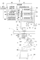
この発明の第1実施形態に係るリンク作動装置の制御装置および制御方法を図面と共に説明する。まず、制御対象となるリンク作動装置を、図1ないし図5と共に説明する。図1および図2に示すように、このリンク作動装置1は、リンク作動装置本体2と、このリンク作動装置本体2を作動させる複数の姿勢制御用のアクチュエータ3とを備え、これら姿勢制御用のアクチュエータ3が制御装置4により制御される。図の例では、リンク作動装置本体2が、その基端側で、支持部材5にスペーサ6を介して吊り下げ状態に設置されている。
この発明の第1実施形態に係るリンク作動装置の制御装置および制御方法を図面と共に説明する。まず、制御対象となるリンク作動装置を、図1ないし図5と共に説明する。図1および図2に示すように、このリンク作動装置1は、リンク作動装置本体2と、このリンク作動装置本体2を作動させる複数の姿勢制御用のアクチュエータ3とを備え、これら姿勢制御用のアクチュエータ3が制御装置4により制御される。図の例では、リンク作動装置本体2が、その基端側で、支持部材5にスペーサ6を介して吊り下げ状態に設置されている。
リンク作動装置本体2の先端側には、先端取付部材7を介してエンドエフェクタ8が搭載されている。アクチュエータ3は例えばサーボモータであり、位置検出器35を有している。エンドエフェクタ8は、例えばレーザ加工ヘッド、ディスペンサ、インクジェットノズル、溶接トーチ等であり、テーブル装置50(図2)上のワークWの表面である作業面60上で作業を行う。
リンク作動装置本体2は、前述の図9のリンク作動装置1と基本的に同じ構成である。このため一部が繰り返しになるが、各部の構造をより詳しく説明する。図3に示すように、リンク作動装置本体2は、3組のリンク機構11,12,13(以下、「11~13」と表記する)を具備する。なお、図1および図2では、リンク機構11の形状につき1組のみを示し、図1では他の2組のリンク機構12,13について、制御の説明のために二点鎖線の四角形で示している。
各リンク機構11,12,13は、基端側の端部リンク部材11a,12a,13a(以下、「11a~13a」と表記する)、中央リンク部材11c,12c,13c(以下、「11c~13c」と表記する)、および先端側の端部リンク部材11b,12b,13b(以下、「11b~13b」と表記する)で構成され、4つの回転対偶からなる4節連鎖のリンク機構をなす。
基端側および先端側の端部リンク部材11a~13a,11b~13bはL字状をなし、一端がそれぞれ基端側のリンクハブ14および先端側のリンクハブ15に回転自在に連結されている。中央リンク部材11c~13cは、両端に基端側および先端側の端部リンク部材11a~13a,11b~13bの他端がそれぞれ回転自在に連結されている。
基端側のリンクハブ14および先端側のリンクハブ15は六角柱状で、外周面を構成する6つの側面16のうちの1つ置きに離れた3つの側面16に、基端側および先端側の端部リンク部材11a~13a,11b~13bがそれぞれ回転自在に連結されている。なお、基端側の端部リンク部材11a~13aは、アームを構成し、以下の説明において、「アーム11a~13a」と称する場合がある。
これら3組のリンク機構11~13のそれぞれは幾何学的に互いに同一形状をなす。すなわち、各リンク機構11~13は、基端側の端部リンク部材11a~13a,先端側の端部リンク部材11b~13bおよび中央リンク部材11c~13cを直線で表現した幾何学モデルが、中央リンク部材11c~13cの中央部に対する基端側部分と先端側部分が対称を成す形状である。
リンク作動装置本体2は、2つ球面リンク機構を組み合わせた構成であって、基端側のリンクハブ14と基端側の端部リンク部材11a~13a、先端側のリンクハブ15と先端側の端部リンク部材11b~13bの各回転対偶、基端側および先端側の端部リンク部材11a~13a,11b~13bと中央リンク部材11c~13cの各回転対偶の中心軸が、基端側と先端側において、それぞれの球面リンク中心PA,PB(図1、図2)で交差している。
また、基端側のリンクハブ14と基端側の端部リンク部材11a~13aの回転対偶と基端側の球面リンク中心PAからの距離、先端側のリンクハブ15と先端側の端部リンク部材11b~13bの回転対偶と先端側の球面リンク中心PBからの距離も同じである。さらに、基端側および先端側の端部リンク部材11a~13a,11b~13bと中央リンク部材11c~13cの各回転対偶と基端側および先端側の球面リンク中心PA,PBからの距離も同じである。基端側および先端側の端部リンク部材11a~13a,11b~13bと中央リンク部材11c~13cとの回転対偶の中心軸は、ある交差角αをもっていてもよいし、平行であってもよい。
つまり、3組のリンク機構11~13は、幾何学的に同一形状をなす。幾何学的に同一形状とは、各リンク部材11a~13a,11b~13b,11c~13cを直線で表現した幾何学モデル、すなわち各回転対偶と、これら回転対偶間を結ぶ直線とで表現したモデルが、中央リンク部材11c~13cの中央部に対する基端側部分と先端側部分が対称を成す形状であることを言う。図4は、一つのリンク機構11を直線で表現した図である。
この実施形態のリンク機構11~13は回転対称タイプで、基端側のリンクハブ14および基端側の端部リンク部材11a~13aと、先端側のリンクハブ15および先端側の端部リンク部材11b~13bとの位置関係が、中央リンク部材11c~13cの中心線Cに対して回転対称となる位置構成になっている。図1は、基端側のリンクハブ14の中心軸QAと先端側のリンクハブ15の中心軸QBとが同一線上にある状態を示し、図2は、基端側のリンクハブ14の中心軸QAに対して先端側のリンクハブ15の中心軸QBが所定の作動角をとった状態を示す。各リンク機構11~13の姿勢が変化しても、基端側と先端側の球面リンク中心PA,PB間の距離Hは変化しない。
図5は、基端側のリンクハブ14と基端側の端部リンク部材11a~13aの連結部を示す断面図である。基端側のリンクハブ14の側面16から軸部18が突出し、この軸部18に複列の軸受17の内輪(図示せず)が外嵌し、基端側の端部リンク部材11a~13aの基端側のリンクハブ14側の一端部に軸受17の外輪(図示せず)が内嵌している。つまり、内輪は基端側のリンクハブ14に固定され、外輪が基端側の端部リンク部材11a~13aと共に回転する構造である。
軸受17は、例えば深溝玉軸受、アンギュラ玉軸受等の玉軸受であって、ナット19による締付けでもって所定の予圧量を付与して固定されている。軸受17としては、図示例のように玉軸受を複列で配列する以外に、ローラ軸受や滑り軸受を用いてもよい。先端側のリンクハブ15と先端側の端部リンク部材11b~13bの連結部も、同様の構造である。
また、基端側の端部リンク部材11a~13aと中央リンク部材11c~13cの連結部も複列の軸受20を介して互いに回転自在に連結されている。すなわち、基端側の端部リンク部材11a~13aの他端部に軸受20の外輪(図示せず)が外嵌し、中央リンク部材11c~13cに設けた軸部21に軸受20の内輪(図示せず)が外嵌している。軸受20は、例えば深溝玉軸受、アンギュラ玉軸受等の玉軸受であって、ナット22による締付けでもって所定の予圧量を付与して固定されている。軸受20としては、図示例のように玉軸受を複列で配列する以外に、ローラ軸受や滑り軸受を用いてもよい。先端側の端部リンク部材11b~13bと中央リンク部材11c~13cの連結部も、同様の構造である。
リンク機構11~13において、下記の(1)~(3)の条件を満たすとき、中央リンク部材11c~13cの対称面に対して中央リンク部材11c~13cと、基端側および先端側の端部リンク部材11a~13a,11b~13bとの角度位置関係を基端側と先端側で同じにすれば、幾何学的対称性から基端側のリンクハブ14および基端側の端部リンク部材11a~13aと、先端側のリンクハブ15および先端側の端部リンク部材11b~13bとは同じに動き、基端側と先端側は同じ回転角になって等速で回転することになる。この等速回転するときの中央リンク部材11c~13cの対称面を等速二等分面という。
(1)基端側および先端側の端部リンク部材11a~13a,11b~13bの軸部18の角度および長さ(球面リンク中心PA,PBからの長さ)が互いに等しい。
(2)基端側の端部リンク部材11a~13aと先端側の11b~13bの幾何学的形状が等しい。
(3)中央リンク部材11c~13cについても基端側と先端側で形状が等しい。
(2)基端側の端部リンク部材11a~13aと先端側の11b~13bの幾何学的形状が等しい。
(3)中央リンク部材11c~13cについても基端側と先端側で形状が等しい。
このため、基端側のリンクハブ14および先端側のリンクハブ15を共有する同じ幾何学形状のリンク機構11~13を円周上に複数配置させることにより、複数のリンク機構11~13が矛盾なく動ける位置として中央リンク部材11c~13cが等速二等分面上のみの動きに限定される。これにより基端側と先端側は任意の作動角をとっても等速回転が得られる。
各リンク機構11~13における4つの回転対偶の回転部、つまり、基端側のリンクハブ14と基端側の端部リンク部材11a~13aとの連結部分、先端側のリンクハブ15と先端側の端部リンク部材11b~13bとの連結部分、および基端側および先端側の端部リンク部材11a~13a,11b~13bと中央リンク部材11c~13cとの2つの連結部分を軸受構造となっている。これにより、その連結部分での摩擦抵抗を抑えて回転抵抗の軽減を図ることができ、滑らかな動力伝達を確保できると共に耐久性を向上できる。
このリンク作動装置本体2の構成によれば、基端側のリンクハブ14に対する先端側のリンクハブ15の可動範囲を広くとれる。例えば、基端側のリンクハブ14の中心軸QAと先端側のリンクハブ15の中心軸QBの折れ角θの最大値(最大折れ角)を約±90°とすることができる。また、基端側のリンクハブ14に対する先端側のリンクハブ15の旋回角φを0°~360°の範囲で設定できる。
図1および図2において、前記複数のアクチュエータ3は、支持部材5の上に円周方向に等配で設置されている。アクチュエータ3の個数は、リンク機構11,12,13と同数の3個である。ただし、アクチュエータ3の個数が2個であっても、リンク作動装置本体2の動作を規定できる。この実施形態では、アクチュエータ3はモータからなり、その出力軸3aにピニオン30が設けられている。一方、端部側の端部リンク部材11a~13aにおける軸部18との回転対偶部に連結部材31(図5)が固定して取付けられ、この連結部材31に、ピニオン30と噛み合う扇形ギア32が設けられている。扇形ギア32の中心軸は、軸部18(図5)の中心軸と一致する。ピニオン30と扇形ギア32とで減速機33を構成する。
各アクチュエータ3を回転駆動すると、その回転が減速機構33を介して軸部18(図5)に伝達されて、基端側のリンクハブ14に対する基端側の端部リンク部材であるアーム11a~13aの角度が変更される。これにより、基端側のリンクハブ14に対する先端側のリンクハブ15の姿勢が決まる。この姿勢は、折れ角θ(図3)および旋回角φ(図3)により規定される。アーム11a~13aの回転角β1,β2,β3は、回転角検出手段35により検出された値と減速機構33の減速比との値から算出される。
次に、図1と共に制御装置4について説明する。制御装置4は、基端側のリンクハブ14に対する先端側のリンクハブ15の姿勢を始点姿勢から終点姿勢へ変更すると共に、その際、被作業面60上の経路を作業点が指令入力手段40で設定された目標移動速度Vで移動して姿勢変更するように、各アクチュエータ3を制御する装置である。作業点は、例えばエンドエフェクタ8の先端部となる点である。
始点姿勢は、現在の姿勢であり、個々のアーム11a~13aの始点は、現在の各アーム11a~13aの位置である。この実施形態では、始点は、前回移動時の終点であるが、各回転角検出手段35により検出された値と減速機構33の減速比との値から算出される現在位置であっても、定められた基準位置であってもよい。始点姿勢は、この制御装置4に対する外部の指令入力手段40から与えるようにしても良い。
指令入力手段40は、キーボードやマウス等のオペレータの操作により入力を行う機器であっても、またこの制御装置4に対する上位の制御装置や、外部の情報機器類から情報を得る通信手段や、記憶媒体のドライブ手段であっても良い。
制御装置4は、コンピュータによる数値制御式のものであり、分割区間設定手段42、アーム回転速度計算手段43、区間対応設定情報記憶手段46、および姿勢変更制御手段41を備える。
分割区間設定手段42は、エンドエフェクタ8が作業する被作業面60上のエンドエフェクタ8が移動する始点から終点までの経路を複数または一つの通過点で複数の区間に分割し、通過点の位置を設定する。被作業面60上の始点から終点までの経路は、指令入力手段40から直交座標で入力され、また各通過点も、分割区間設定手段42では、直交座標で示される。
ここで、区間の分割数は、エンドエフェクタ8の被作業面60上を移動する速度が実質的に等速となるよう設定する。経路を通過点で複数の区間に分割する処理は、指令入力手段40からオペレータが入力するようにしても良く、また分割区間設定手段42に分割機能を持たせて自動で分割するようにしても良い。オペレータが入力するように構成する場合、分割区間設定手段42は、単に始点、終点、および通過点の座標を記憶する手段となる。
分割区間設定手段42が各通過点を計算して区分を設定する構成である場合、定められた規則により、始点から終点までの経路を、例えば一定の分割数で等分割し、アーム回転速度計算手段43に回転速度の計算を行わせて、始点から終点までを実質的に等速となるように制御(等速制御)できるか否かを判定させる。等速制御ができない場合は、分割数を変更して、再度アーム回転速度計算手段43に回転速度の計算を行わせる処理を繰り返させ、等速制御ができると判定する処理によって区分を定めても良い。
アーム回転速度計算手段43は、オペレータにより指令入力手段40から入力して指定された目標移動速度および前記各区間の距離から定まる各区間内の移動の時間と、各区間における各アーム11a,12a,13aの回転角移動量とから、各区間における各アーム11a,12a,13aが等速回転する回転速度を計算する。
区間対応設定情報記憶手段46は、区間毎に、アーム回転速度計算手段43で計算された各アーム11a,12a,13aにおける各区間に対応する始点、通過点、または終点であるポイントの位置と、アーム回転速度を記憶する。
姿勢変更制御手段41は、各区間内での各アーム11a~13aの回転速度を回転速度計算手段43で計算された値に設定して、各区間を加減速無しで連続して回転させるように各アクチュエータ3を位置決め制御する。姿勢変更制御手段41は、指令読み出し部51、同期制御部52、およびアクチュエータ3と同数の個別制御部53からなる。
指令読み出し部51は、区間対応設定情報記憶手段46に記憶された各アーム11a,12a,13aの区間毎の各ポイントの位置とアーム回転速度を読み出す。指令読み出し部51は、区間対応設定情報記憶手段46から読み出す代わりに、アーム回転速度計算手段43から各アーム11a,12a,13aの区間毎の各ポイントの位置とアーム回転速度を読み出すようにしても良い。同期制御部52は、各アーム11a~13aが、同時に始点から回転を始め、同時に終点で止まるように、各個別制御部53に対して同期制御を行わせる手段である。
各個別制御部53は、対応するアクチュエータ3を、与えられたポイントからからポイントへポイントツーポイントで位置制御する。個別制御部53は、具体的には、例えばアーム回転角をアクチュエータ移動量に変換する動作量変換部(図示せず)と動作指令生成部(図示せず)とサーボコントローラ部(図示せず)とからなる。動作指令生成部は台形速度制御の速度曲線に従ってパルス払い出し等によってサーボコントローラ部へ動作指令を与える。サーボコントローラ部は、その与えられた動作指令と回転角検出手段35の検出値を用いてフィードバック制御を行う。
アーム回転速度計算手段43で用いる具体的な回転速度の計算方法を説明する。まず簡単な例で説明する。図6にエンドエフェクタ8が作業する平面の被作業面60上の任意の3つのポイント(A、B、C)を示す。3つのポイント(A、B、C)はX-Y直交座標で示された点である。ポイントAとBの間の距離をLab、ポイントBとCの間の距離をLbcとすると、LabとLbcは次の式となる。

被作業平面60上でのエンドエフェクタ8の速度(なぞる速度)をVとすると、Labの距離を移動する時間Tabと、Lbcの距離を移動する時間Tbcは以下の式となる。速度Vは前記目標移動速度である。加減速時間はゼロとして計算する。
Tab=Lab/V
Tbc=Lbc/V
Tab=Lab/V
Tbc=Lbc/V
ポイントA、B、Cにおけるリンクハブの姿勢(折れ角、旋回角)を姿勢A(θa,φa)、姿勢B(θb、φb)、姿勢C(θc、φc)とすると、姿勢A、B、Cに対応する各アーム回転角は、リンクハブとアーム回転角との前記式(1)から、それぞれ回転角A(β1a,β2a、β3a)、回転角B(β1b、β2b、β3b)、回転角C(β1c、β2c、β3c)として関係が成り立つ。ポイントAからBへ移動する時のβ1軸、β2軸、β3軸の各回転角移動量をΔβ1ab、Δβ2ab、Δβ3abとすると、各軸の回転速度である移動速度V1ab、V2ab、V3abは以下の式で表せる。なお、β1軸、β2軸、β3軸の移動とは、それぞれ各アーム11a~13aの回転中心回りの回転を意味する。

上記と同様に、ポイントBからCへ移動する時のβ1軸、β2軸、β3軸の各移動量をΔβ1bc、Δβ2bc、Δβ3bcとすると、各軸の移動速度V1bc、V2bc、V3bcは次の式となる。

アーム回転速度計算手段43は、先端側のリンクハブ15に付加したエンドエフェクタ8が平面の被作業面60上の3つのポイントA→B→Cをなぞる動作の際、β1軸、β2軸、β3軸の各移動量と、上記式より求めた速度を区間毎に設定し、各区間内は加減速なしで連続位置決め制御する。なお、「加減速なしで連続位置決め」とは、止まらずに連続して回転させる意味である。
図7に一般化して示す。同図に示すように、エンドエフェクタ8が平面の被作業面60上の各ポイントを指定された目標移動速度Vでなぞる動作において、nポイント目の直交座標を(Xn、Yn)とし、n-1ポイント目の直交座標を(Xn-1、Yn-1)とし、n-1ポイント目からnポイント目へのβ1軸、β2軸、β3軸の各移動量をΔβ1、Δβ2、Δβ3とすると、Nポイント目に移動する際の各軸の移動速度V1n、V2n、V3nは次の式で表せる。

アーム回転速度計算手段43は、これらの式(2)~(5)に従って、各区間の移動時間Tと、これら各区間における各アーム回転速度である各軸の移動速度V1n、V2n、V3nを計算する。また、アーム回転速度計算手段43は、指令変換部44を有する。指令変換部44は、上記の式(2)~(5)に基づく計算に先立って、被作業面60上の直交座標で示された各ポイントの座標位置を、前述の式(1)に従って各アーム11a~11cの回転に変換し、各軸の移動量Δβ1、Δβ2、Δβ3を求める。
この実施形態の構成によると、このようにエンドエフェクタ8の始点から終点までの移動、つまり先端側のリンクハブ15の始点姿勢A(θa、φa)から終点姿勢B(θb、φb)への移動において、分割区間設定手段42に区間を複数に分割して設定する際に、分割する区間はエンドエフェクタ8が作業する被作業面60上での経路を基準に区間設定する。
アーム回転速度計算手段43は、エンドエフェクタ8の作業面上を移動する速度が始点から終点まで一定の目標移動速度Vとなるように、各区間の移動ごとに各アーム11a,12a,13aの等速回転する回転速度(β1軸、β2軸、β3軸の移動速度)を計算する。この回転速度の計算は、指定された目標移動速度Vおよび各区間の距離から定まる各区間内の移動の時間と、各区間における各アーム11a,12a,13aの回転角移動量とから行う。
姿勢変更制御手段41は、各区間内での各アーム11a~13aの回転速度を、アーム回転速度計算手段43により計算された回転速度に設定し、この設定された回転速度で、各区間内を加減速無しで連続して回転させるように各アクチュエータ3を位置決め制御する。
これにより、エンドエフェクタ8が作業する平面の被作業面(直交座標)上の複数点を実質的に等速で動作することが可能となる。すなわち、始点から終点への位置決め制御が、途中の被作業面上の任意の点を加減速無しで通過することになる。そのため、エンドエフェクタ8として、例えばレーザ加工ヘッド、ディスペンサ、インクジェットノズル、溶接器具等をリンクに付加した際、レーザの加工ムラやディスペンサ、インクジェットによる塗布ムラ、溶接による溶接ムラをなくすことができる。
<第2実施形態>
この発明の第2実施形態を、図8を参照して説明する。第2実施形態において、特に説明した事項の他は、第1実施形態と同様である。第2実施形態は、図1における分割区間設定手段42、アーム回転速度計算速度計算手段43、および区間対応設定情報記憶手段46の機能について、第1実施形態とは一部を異ならせたものである。区間対応設定情報記憶手段46は、記憶する値が第1実施形態とは異なる。
この発明の第2実施形態を、図8を参照して説明する。第2実施形態において、特に説明した事項の他は、第1実施形態と同様である。第2実施形態は、図1における分割区間設定手段42、アーム回転速度計算速度計算手段43、および区間対応設定情報記憶手段46の機能について、第1実施形態とは一部を異ならせたものである。区間対応設定情報記憶手段46は、記憶する値が第1実施形態とは異なる。
第1実施形態では、エンドエフェクタ8の被作業面60が平面である場合の等速移動について示したが、これと同様に被作業面60が球面である場合に、この球面状の被作業面60上でのエンドエフェクタ8の先端の動作を等速にすることもできる。これは、先端側のリンクハブ15の動作を等速にすることになる。
ここでは、先端側のリンクハブ15の動作を等速にする時の各軸(β1軸、β2軸、β3軸)の移動速度について示す。図8に示すように、2つのポイント(n-1),nにおける先端側リンクハブ15の姿勢(折れ角、旋回角)を姿勢A(θn-1、φn-1)、姿勢B(θN、φn)とする。姿勢A、Bに対応するアーム回転角は、前述の式(1)より、それぞれ回転角A(β1n-1、β2n-1、β3n-1)、回転角B(β1n、β2n、β3n)として関係が成り立つ。また、姿勢A(θn-1、φn-1)から姿勢B(θn、φn)へ移動したときの回転角移動量γ(rad)は、球面三角法より以下の式で近似して表せる。

先端側リンクハブ15の指定された目標移動速度をV(rad/s)とすると、移動量γ(rad)にかかる時間は次の式となる。
T=γ/V
ポイント(n-1)からポイントnへ移動するときの各軸の回転角の移動速度である回転速度V1n、V2n、V3nは、次の式となる。
T=γ/V
ポイント(n-1)からポイントnへ移動するときの各軸の回転角の移動速度である回転速度V1n、V2n、V3nは、次の式となる。

β1軸、β2軸、β3軸の各移動量と、上記式より求めた速度を区画毎、つまりポイント毎に設定し、各ポイントを加減速なしで連続位置決め制御する。
図1と共に説明すると、図1の分割区間設定手段42は、球面からなる被作業面60上のエンドエフェクタ8が移動する始点から終点までの経路を通過点で複数の区間に分割する。すなわち、上述の各ポイントを定める。アーム回転速度計算手段43は、指定された目標移動速度Vおよび各区間の距離から定まる各区間内の移動の時間Tと、各区間における各アーム11a,12a,13aの回転角移動量γとから、上記式(6)~(8)に基づいて、回転速度V1n、V2n、V3nを計算する。ここで、回転速度V1n、V2n、V3nは、各区間における各アーム11a,12a,13aが等速回転する回転角の移動速度である。
姿勢変更制御手段41は、ポイント間の各区間内での各アーム11a,12a,13aの回転速度V1n、V2n、V3nを、回転速度計算手段43で計算された値に設定し、各区間を加減速無しで連続して回転させるように各アクチュエータ3を位置決め制御する。
このように、被作業面60が球面である場合も、エンドエフェクタ8が被作業面60上を実質的に等速で移動しながら作業をすることができる。
<第3実施形態>
この発明の第3実施形態を説明する。第3実施形態は、図2に示すテーブル装置50が移動することによって対象ワークWがリンク作動装置1のエンドエフェクタ8に対して相対移動する場合に、その相対移動の速度を等速とする例である。テーブル装置50は、テーブル面が直交2軸方向に移動するXYテーブルであり、同図の例では表面が平面の被作業面60となる対象ワークWを移動させる。ただし、リンク作動装置1をテーブル装置50に搭載してリンク作動装置1を移動させ、ワークWを位置固定としても良い。
この発明の第3実施形態を説明する。第3実施形態は、図2に示すテーブル装置50が移動することによって対象ワークWがリンク作動装置1のエンドエフェクタ8に対して相対移動する場合に、その相対移動の速度を等速とする例である。テーブル装置50は、テーブル面が直交2軸方向に移動するXYテーブルであり、同図の例では表面が平面の被作業面60となる対象ワークWを移動させる。ただし、リンク作動装置1をテーブル装置50に搭載してリンク作動装置1を移動させ、ワークWを位置固定としても良い。
第3実施形態において、特に説明する事項の他は、第1実施形態と同様である。第3実施形態は、図1における分割区間設定手段42、アーム回転速度計算速度計算手段43、および区間対応設定情報記憶手段46の機能について、第1実施形態とは一部が異なっている。区間対応設定情報記憶手段46は、記憶する値が第1実施形態とは異なる。
第1実施形態においては、リンク作動装置1と被作業面60上の対象ワークWの位置は固定であったが、実際にレーザ加工や塗布、溶接等を行う場合、対象ワークWをXYテーブル、すなわち、テーブル可動面が直交2軸方向に移動可能なテーブル装置上に搭載するか、またはリンク作動装置1をXYテーブルに搭載する構成が一般的となる。
ここでは、リンク作動装置1の3軸(β1軸、β2軸、β3軸)と、XYテーブルからなるテーブル装置50(図2)の2軸(X軸、Y軸)とが可動であるテーブル併用リンク作動装置のシステム構成において、エンドエフェクタ8が平面状の被作業平面60上の各ポイントを指定された速度Vで等速移動する際の合成速度(移動速度)Vnについて示す。
対象ワークWの直交座標は、図7と同様に、nポイント目の直交座標を(Xn、Yn)とし、n-1ポイント目の直交座標を(Xn-1、Yn-1)とする。n-1ポイント目からnポイント目へのβ1軸、β2軸、β3軸、X軸、Y軸の各移動量をΔβ1、Δβ2、Δβ3、Δx、Δyとすると、nポイント目に移動する際の各軸の移動速度V1n、V2n、V3n、Vxn、Vynは次の式で表せる。β1軸、β2軸、β3軸の移動速度は、回転角の移動速度である。

アーム回転速度計算手段43は、先端側リンクハブ15に付加したエンドエフェクタ8が平面状の被作業面60上の各ポイントをなぞる動作の際、β1軸、β2軸、β3軸、X軸、Y軸の各移動量と、上記式より求めた速度を区間毎、つまりポイント毎に設定し、各ポイントを加減速なしで連続位置決め制御する。
図1と共に説明すると、図1の分割区間設定手段42は、XY方向に相対移動する平面からなる被作業面60上の、エンドエフェクタ8が相対移動する始点から終点までの経路を通過点で複数の区間に分割する。すなわち上述の各ポイントを定める。
アーム回転速度計算手段43は、指定された目標移動速度Vおよび各区間の距離から定まる各区間内の移動の時間Tと、各区間における各アーム11a,12a,13aの回転角移動量Δβ1、Δβ2、Δβ3とから、上記式(9)~(11),(14)に基づいて、回転速度V1n、V2n、V3nを計算する。回転速度V1n、V2n、V3nは、各区間における各アーム11a,12a,13aが等速回転する回転角の移動速度である。アーム回転速度計算手段43は、各軸の回転速度の他に、X軸、Y軸の移動速度Vxn、Vynを上記式(12)、(13)、(14)で計算する機能を付加した構成としても良い。
姿勢変更制御手段41は、ポイント間の各区間内での各アーム8の回転速度V1n、V2n、V3nを回転速度計算手段43で計算された値に設定して、各区間を加減速無しで連続して回転させるように各アクチュエータ3を位置決め制御する。X軸、Y軸の制御手段(図示せず)は、上記式(12)、(13)に基づいて計算したX軸、Y軸の移動速度Vxn、Vynを設定して、その速度でテーブル装置50の各軸を移動させる。
このように、リンク作動装置1がテーブル装置50によって相対移動する場合に、エンドエフェクタ8がその相対移動を加味して被作業面60上を実質的に等速で移動しながら作業をするように制御することができる。
なお、上記第1~3実施形態では、いずれも、実使用時に制御装置4が各通過点の位置(各区間)の設定、および各区間におけるアーム回転速度の計算を行うようになっている。これに代えて、これら各通過点の位置と、各区間における各アーム11a,12a,13aの回転速度について、リンク作動装置1の実使用の前に計算した値を区間対応設定情報記憶手段46に記憶させておき、姿勢変更制御手段41は、実使用時は、区間対応設定情報記憶手段46に記憶された各通過点の位置と、各アーム11a,12a,13aの回転速度を読み出して制御するようにしても良い。この場合、実使用の前に、各通過点の位置と、各区間における各アーム11a,12a,13aの回転速度を設定/計算する装置は、姿勢変更制御手段41を有する制御装置4とは別のコンピュータに設けられていても良い。
リンク作動装置1を用いて同じ作業を繰り返して行う場合がある。そのような場合、各区間における各アーム11a,12a,13aの回転速度を予め区間対応設定情報記憶手段46に記憶させておき、姿勢変更制御手段41はその記憶内容を読み出して制御を行うようにすれば、区間の設定や回転速度の計算を毎回行う必要がなく、制御が簡単で且つ迅速に行える。一度だけの作業であっても、予め区間およびアーム回転速度を予め計算して設定しておくことが便利な場合がある。なお、上記の「実使用時」とは、試し運転を除く実際にエンドエフェクタ8で加工や処理を行うときを言う。
本発明は、以上の実施形態に限定されるものでなく、本発明の要旨を逸脱しない範囲内で、種々の追加、変更または削除が可能である。したがって、そのようなものも本発明の範囲内に含まれる。
1…リンク作動装置
3…アクチュエータ
4…制御装置
8…エンドエフェクタ
14…基端側のリンクハブ
15…先端側のリンクハブ
11~13…リンク機構
11a,12a,13a…基端側の端部リンク部材(アーム)
11b,12b,13b…先端側の端部リンク部材
11c,12c,13c…中央リンク部材
40…指令入力手段
41…姿勢変更制御手段
42…分割区間設定手段
43…アーム回転速度計算手段
44…指令変換部
46…区間対応設定情報記憶手段
50…テーブル装置
60…被作業面
61…経路
3…アクチュエータ
4…制御装置
8…エンドエフェクタ
14…基端側のリンクハブ
15…先端側のリンクハブ
11~13…リンク機構
11a,12a,13a…基端側の端部リンク部材(アーム)
11b,12b,13b…先端側の端部リンク部材
11c,12c,13c…中央リンク部材
40…指令入力手段
41…姿勢変更制御手段
42…分割区間設定手段
43…アーム回転速度計算手段
44…指令変換部
46…区間対応設定情報記憶手段
50…テーブル装置
60…被作業面
61…経路
Claims (7)
- 基端側のリンクハブに対し先端側のリンクハブを、3組以上のリンク機構を介して姿勢を変更可能に連結し、前記各リンク機構は、それぞれ前記基端側のリンクハブおよび先端側のリンクハブに一端が回転可能に連結された基端側および先端側の端部リンク部材と、これら基端側および先端側の端部リンク部材の他端に両端がそれぞれ回転可能に連結された中央リンク部材とでなり、前記各リンク機構は、このリンク機構を直線で表現した幾何学モデルが、前記中央リンク部材の中央部に対する基端側部分と先端側部分とが対称を成す形状であり、前記3組以上のリンク機構のうち2組以上のリンク機構に、前記基端側の端部リンク部材であるアームを回転させることにより、前記基端側のリンクハブに対する前記先端側のリンクハブの姿勢を任意に変更させるアクチュエータを設け、前記先端側のリンクハブにエンドエフェクタを設置したリンク作動装置、を制御する制御装置であって、
前記エンドエフェクタが作業する被作業面上の前記エンドエフェクタが移動する始点から終点までの経路を通過点で複数の区間に分割し、前記通過点の位置を設定する分割区間設定手段と、
指定された一定速度の目標移動速度および前記各区間の距離から定まる各区間内の移動の時間と、前記各区間における前記各アームの回転角移動量とから、前記各区間における前記各アームが等速回転する回転速度を計算するアーム回転速度計算手段と、
前記各区間内での前記各アームの回転速度を前記回転速度計算手段で計算された値として、前記各区間を加減速無しで連続して回転させるように前記各アクチュエータを位置決め制御する姿勢変更制御手段と、
を備えたリンク作動装置の制御装置。 - 請求項1に記載のリンク作動装置の制御装置において、前記エンドエフェクタが作業する前記被作業面は平面であるリンク作動装置の制御装置。
- 請求項2に記載のリンク作動装置の制御装置において、前記アーム回転速度計算手段は、前記始点、終点、および各通過点のいずれかの点である各ポイントへの前記各アームの回転速度を、前記被作業面を示す直交座標系の任意の2ポイント間の距離と前記目標移動速度から求められる時間と、前記2ポイント間の前記各アームの回転角移動量とから、前記各区間における前記各アームの回転速度を計算するリンク作動装置の制御装置。
- 請求項1に記載のリンク作動装置の制御装置において、前記エンドエフェクタが作業する前記被作業面は球面であるリンク作動装置の制御装置。
- 請求項4に記載のリンク作動装置の制御装置において、前記アーム回転速度計算手段は、前記始点、終点、および各通過点のいずれかの点である各ポイントへの前記各アームの回転速度を、球面三角法より得られる任意の2ポイント間の移動量と前記目標移動速度から求められる時間と、前記2ポイント間の前記各アームの回転角移動量とから、前記各区間における前記各アームの回転速度を計算するリンク作動装置の制御装置。
- 請求項1ないし請求項5のいずれか1項に記載のリンク作動装置の制御装置において、前記各区間における、前記各通過点の位置と、前記各区間における前記各アームの回転速度につき、リンク作動装置の実使用の前に計算した値を記憶する区間対応設定情報記憶手段を有し、前記姿勢変更制御手段は、実使用時は、前記区間対応設定情報記憶手段に記憶された前記各通過点の位置と、前記各アームの回転速度を読み出して制御するリンク作動装置の制御装置。
- 基端側のリンクハブに対し先端側のリンクハブを、3組以上のリンク機構を介して姿勢を変更可能に連結し、前記各リンク機構は、それぞれ前記基端側のリンクハブおよび先端側のリンクハブに一端が回転可能に連結された基端側および先端側の端部リンク部材と、これら基端側および先端側の端部リンク部材の他端に両端がそれぞれ回転可能に連結された中央リンク部材とでなり、前記各リンク機構は、このリンク機構を直線で表現した幾何学モデルが、前記中央リンク部材の中央部に対する基端側部分と先端側部分とが対称を成す形状であり、前記3組以上のリンク機構のうち2組以上のリンク機構に、前記基端側の端部リンク部材であるアームを回転させることにより、前記基端側のリンクハブに対する前記先端側のリンクハブの姿勢を任意に変更させるアクチュエータを設け、前記先端側のリンクハブにエンドエフェクタを設置したリンク作動装置を制御する制御方法であって、
前記エンドエフェクタが作業する被作業面上の前記エンドエフェクタが移動する始点から終点までの経路を通過点で複数の区間に分割し、
指定された目標移動速度および前記各区間の距離から定まる各区間内の移動の時間と、前記各区間における前記各アームの回転角移動量とから、前記各区間における前記各アームの回転速度を計算し、
前記各区間内での前記各アームの回転速度を前記の計算された値として、前記各区間を加減速無しで連続して回転させるように前記各アクチュエータを位置決め制御することで、
前記被作業面上の分割された複数点間を始点から終点まで実質的に一定速度に動作させるリンク作動装置の制御方法。
Priority Applications (2)
| Application Number | Priority Date | Filing Date | Title |
|---|---|---|---|
| EP15751572.7A EP3109010B1 (en) | 2014-02-20 | 2015-02-12 | Device and method for controlling link actuation device |
| US15/233,409 US10065310B2 (en) | 2014-02-20 | 2016-08-10 | Device and method for controlling link actuation device |
Applications Claiming Priority (2)
| Application Number | Priority Date | Filing Date | Title |
|---|---|---|---|
| JP2014-030425 | 2014-02-20 | ||
| JP2014030425A JP6271288B2 (ja) | 2014-02-20 | 2014-02-20 | リンク作動装置の制御装置および制御方法 |
Related Child Applications (1)
| Application Number | Title | Priority Date | Filing Date |
|---|---|---|---|
| US15/233,409 Continuation US10065310B2 (en) | 2014-02-20 | 2016-08-10 | Device and method for controlling link actuation device |
Publications (1)
| Publication Number | Publication Date |
|---|---|
| WO2015125678A1 true WO2015125678A1 (ja) | 2015-08-27 |
Family
ID=53878183
Family Applications (1)
| Application Number | Title | Priority Date | Filing Date |
|---|---|---|---|
| PCT/JP2015/053739 WO2015125678A1 (ja) | 2014-02-20 | 2015-02-12 | リンク作動装置の制御装置および制御方法 |
Country Status (4)
| Country | Link |
|---|---|
| US (1) | US10065310B2 (ja) |
| EP (1) | EP3109010B1 (ja) |
| JP (1) | JP6271288B2 (ja) |
| WO (1) | WO2015125678A1 (ja) |
Families Citing this family (13)
| Publication number | Priority date | Publication date | Assignee | Title |
|---|---|---|---|---|
| JP6453066B2 (ja) * | 2014-12-05 | 2019-01-16 | Ntn株式会社 | リンク作動装置の制御方法 |
| JP2017121687A (ja) * | 2016-01-08 | 2017-07-13 | トヨタ自動車株式会社 | ロボットシステムの制御方法 |
| JP6275196B2 (ja) * | 2016-06-05 | 2018-02-07 | Ntn株式会社 | リンク作動装置の操作装置およびリンク作動システム |
| JP6800044B2 (ja) | 2017-02-24 | 2020-12-16 | Ntn株式会社 | リンク作動装置の制御装置および制御方法 |
| CN111093912B (zh) | 2017-09-08 | 2023-02-17 | Ntn株式会社 | 采用平行连杆机构的作业装置 |
| JP6472854B1 (ja) * | 2017-09-11 | 2019-02-20 | Ntn株式会社 | 作業装置 |
| JP6498738B1 (ja) * | 2017-09-26 | 2019-04-10 | Ntn株式会社 | リンク作動装置 |
| JP7140508B2 (ja) | 2018-02-26 | 2022-09-21 | Ntn株式会社 | パラレルリンク機構を用いた作業装置およびその制御方法 |
| JP7225560B2 (ja) * | 2018-04-26 | 2023-02-21 | セイコーエプソン株式会社 | 制御装置、ロボットシステム、及び表示制御方法 |
| JP2020091014A (ja) * | 2018-12-07 | 2020-06-11 | Ntn株式会社 | リンク作動装置及びリンク作動装置の原点位置決め方法 |
| CN109822566B (zh) * | 2019-01-15 | 2021-10-22 | 深圳镁伽科技有限公司 | 机器人控制方法、系统及存储介质 |
| JP7340196B2 (ja) | 2019-06-05 | 2023-09-11 | 国立大学法人九州工業大学 | リンク作動装置 |
| JP7464514B2 (ja) | 2020-12-22 | 2024-04-09 | Ykk Ap株式会社 | 移動制限装置及び建具 |
Citations (5)
| Publication number | Priority date | Publication date | Assignee | Title |
|---|---|---|---|---|
| JPS61168019A (ja) * | 1985-01-21 | 1986-07-29 | Nissan Motor Co Ltd | 補間方法 |
| JP2005056171A (ja) * | 2003-08-05 | 2005-03-03 | Fanuc Ltd | 制御装置 |
| JP2005144627A (ja) * | 2003-11-18 | 2005-06-09 | Ntn Corp | リンク作動装置 |
| JP2013059852A (ja) * | 2011-08-23 | 2013-04-04 | Panasonic Corp | パラレルリンクロボットおよびその動作教示方法 |
| JP2013215864A (ja) * | 2012-04-12 | 2013-10-24 | Panasonic Corp | 塗布教示方法 |
Family Cites Families (9)
| Publication number | Priority date | Publication date | Assignee | Title |
|---|---|---|---|---|
| JP2004261886A (ja) * | 2003-02-18 | 2004-09-24 | Ntn Corp | リンク作動装置 |
| JP2010260139A (ja) * | 2009-05-08 | 2010-11-18 | Ntn Corp | 遠隔操作型加工ロボット |
| JP5528207B2 (ja) * | 2010-05-19 | 2014-06-25 | Ntn株式会社 | リンク作動装置 |
| JP5675258B2 (ja) * | 2010-10-14 | 2015-02-25 | Ntn株式会社 | リンク作動装置 |
| JP2014504397A (ja) * | 2010-11-24 | 2014-02-20 | サムスン ヘビー インダストリーズ カンパニー リミテッド | ワイヤを用いた自律移動装置の制御システム及びその方法 |
| JP2013068280A (ja) * | 2011-09-22 | 2013-04-18 | Ntn Corp | リンク作動装置 |
| JP5973201B2 (ja) * | 2012-03-28 | 2016-08-23 | Ntn株式会社 | リンク作動装置の操作装置 |
| US9522469B2 (en) | 2012-03-23 | 2016-12-20 | Ntn Corporation | Link actuation device |
| JP5864322B2 (ja) * | 2012-03-23 | 2016-02-17 | Ntn株式会社 | リンク作動装置の制御方法およびその制御装置 |
-
2014
- 2014-02-20 JP JP2014030425A patent/JP6271288B2/ja active Active
-
2015
- 2015-02-12 WO PCT/JP2015/053739 patent/WO2015125678A1/ja active Application Filing
- 2015-02-12 EP EP15751572.7A patent/EP3109010B1/en active Active
-
2016
- 2016-08-10 US US15/233,409 patent/US10065310B2/en active Active
Patent Citations (5)
| Publication number | Priority date | Publication date | Assignee | Title |
|---|---|---|---|---|
| JPS61168019A (ja) * | 1985-01-21 | 1986-07-29 | Nissan Motor Co Ltd | 補間方法 |
| JP2005056171A (ja) * | 2003-08-05 | 2005-03-03 | Fanuc Ltd | 制御装置 |
| JP2005144627A (ja) * | 2003-11-18 | 2005-06-09 | Ntn Corp | リンク作動装置 |
| JP2013059852A (ja) * | 2011-08-23 | 2013-04-04 | Panasonic Corp | パラレルリンクロボットおよびその動作教示方法 |
| JP2013215864A (ja) * | 2012-04-12 | 2013-10-24 | Panasonic Corp | 塗布教示方法 |
Also Published As
| Publication number | Publication date |
|---|---|
| EP3109010A4 (en) | 2018-01-24 |
| US20160361816A1 (en) | 2016-12-15 |
| JP2015155124A (ja) | 2015-08-27 |
| JP6271288B2 (ja) | 2018-01-31 |
| EP3109010B1 (en) | 2019-03-27 |
| US10065310B2 (en) | 2018-09-04 |
| EP3109010A1 (en) | 2016-12-28 |
Similar Documents
| Publication | Publication Date | Title |
|---|---|---|
| WO2015125678A1 (ja) | リンク作動装置の制御装置および制御方法 | |
| US9037293B2 (en) | Robot | |
| JP6502115B2 (ja) | リンク作動装置を用いた多関節ロボット | |
| Wannasuphoprasit et al. | Cobot control | |
| JP5701055B2 (ja) | 7軸多関節ロボットの制御方法、制御プログラム及びロボット制御装置 | |
| JP6324033B2 (ja) | リンク作動装置 | |
| JP6229324B2 (ja) | ロボット、ロボット制御装置およびロボットの制御方法 | |
| JP6602620B2 (ja) | 組合せ型リンク作動装置 | |
| JP6453066B2 (ja) | リンク作動装置の制御方法 | |
| KR102026785B1 (ko) | 로봇 팔 및 로봇 손목 | |
| WO2017043420A1 (ja) | リンク作動装置を用いた複合作業装置 | |
| JP2014217913A (ja) | パラレルリンクロボットの動作教示方法およびパラレルリンクロボット | |
| JP6883073B2 (ja) | リンク作動装置を用いた多関節ロボット | |
| JP2016147350A (ja) | リンク作動装置を用いた多関節ロボット | |
| WO2016084685A1 (ja) | パラレルリンク機構を用いた作業装置 | |
| JP7140508B2 (ja) | パラレルリンク機構を用いた作業装置およびその制御方法 | |
| US11130229B2 (en) | Link operating device control device and control method | |
| JP6215623B2 (ja) | リンク作動装置の制御装置 | |
| JP2017228318A (ja) | リンク作動装置の制御装置 | |
| JP2016003754A (ja) | 減速機、ロボットおよびロボットシステム | |
| KR20120119622A (ko) | 강체 바에 의하여 구동력을 전달하는 메커니즘을 가지는 인간형 로봇 핸드 | |
| JP7414426B2 (ja) | ロボットシステム | |
| JP2014188602A (ja) | リンク作動装置の制御装置 | |
| JP6563658B2 (ja) | パラレルリンク機構を用いた作業装置 | |
| JP3278798B2 (ja) | 円加工装置 |
Legal Events
| Date | Code | Title | Description |
|---|---|---|---|
| 121 | Ep: the epo has been informed by wipo that ep was designated in this application |
Ref document number: 15751572 Country of ref document: EP Kind code of ref document: A1 |
|
| REEP | Request for entry into the european phase |
Ref document number: 2015751572 Country of ref document: EP |
|
| WWE | Wipo information: entry into national phase |
Ref document number: 2015751572 Country of ref document: EP |
|
| NENP | Non-entry into the national phase |
Ref country code: DE |