WO2015115394A1 - 耐食性溶射皮膜、その形成方法およびその形成用溶射装置 - Google Patents
耐食性溶射皮膜、その形成方法およびその形成用溶射装置 Download PDFInfo
- Publication number
- WO2015115394A1 WO2015115394A1 PCT/JP2015/052111 JP2015052111W WO2015115394A1 WO 2015115394 A1 WO2015115394 A1 WO 2015115394A1 JP 2015052111 W JP2015052111 W JP 2015052111W WO 2015115394 A1 WO2015115394 A1 WO 2015115394A1
- Authority
- WO
- WIPO (PCT)
- Prior art keywords
- corrosion
- flame
- resistant
- forming
- sprayed coating
- Prior art date
- Legal status (The legal status is an assumption and is not a legal conclusion. Google has not performed a legal analysis and makes no representation as to the accuracy of the status listed.)
- Ceased
Links
Images

Classifications
-
- C—CHEMISTRY; METALLURGY
- C09—DYES; PAINTS; POLISHES; NATURAL RESINS; ADHESIVES; COMPOSITIONS NOT OTHERWISE PROVIDED FOR; APPLICATIONS OF MATERIALS NOT OTHERWISE PROVIDED FOR
- C09D—COATING COMPOSITIONS, e.g. PAINTS, VARNISHES OR LACQUERS; FILLING PASTES; CHEMICAL PAINT OR INK REMOVERS; INKS; CORRECTING FLUIDS; WOODSTAINS; PASTES OR SOLIDS FOR COLOURING OR PRINTING; USE OF MATERIALS THEREFOR
- C09D5/00—Coating compositions, e.g. paints, varnishes or lacquers, characterised by their physical nature or the effects produced; Filling pastes
- C09D5/08—Anti-corrosive paints
- C09D5/10—Anti-corrosive paints containing metal dust
- C09D5/103—Anti-corrosive paints containing metal dust containing Al
-
- B—PERFORMING OPERATIONS; TRANSPORTING
- B05—SPRAYING OR ATOMISING IN GENERAL; APPLYING FLUENT MATERIALS TO SURFACES, IN GENERAL
- B05B—SPRAYING APPARATUS; ATOMISING APPARATUS; NOZZLES
- B05B7/00—Spraying apparatus for discharge of liquids or other fluent materials from two or more sources, e.g. of liquid and air, of powder and gas
- B05B7/16—Spraying apparatus for discharge of liquids or other fluent materials from two or more sources, e.g. of liquid and air, of powder and gas incorporating means for heating or cooling the material to be sprayed
- B05B7/1606—Spraying apparatus for discharge of liquids or other fluent materials from two or more sources, e.g. of liquid and air, of powder and gas incorporating means for heating or cooling the material to be sprayed the spraying of the material involving the use of an atomising fluid, e.g. air
- B05B7/1613—Spraying apparatus for discharge of liquids or other fluent materials from two or more sources, e.g. of liquid and air, of powder and gas incorporating means for heating or cooling the material to be sprayed the spraying of the material involving the use of an atomising fluid, e.g. air comprising means for heating the atomising fluid before mixing with the material to be sprayed
- B05B7/162—Spraying apparatus for discharge of liquids or other fluent materials from two or more sources, e.g. of liquid and air, of powder and gas incorporating means for heating or cooling the material to be sprayed the spraying of the material involving the use of an atomising fluid, e.g. air comprising means for heating the atomising fluid before mixing with the material to be sprayed and heat being transferred from the atomising fluid to the material to be sprayed
- B05B7/1626—Spraying apparatus for discharge of liquids or other fluent materials from two or more sources, e.g. of liquid and air, of powder and gas incorporating means for heating or cooling the material to be sprayed the spraying of the material involving the use of an atomising fluid, e.g. air comprising means for heating the atomising fluid before mixing with the material to be sprayed and heat being transferred from the atomising fluid to the material to be sprayed at the moment of mixing
-
- B—PERFORMING OPERATIONS; TRANSPORTING
- B05—SPRAYING OR ATOMISING IN GENERAL; APPLYING FLUENT MATERIALS TO SURFACES, IN GENERAL
- B05B—SPRAYING APPARATUS; ATOMISING APPARATUS; NOZZLES
- B05B7/00—Spraying apparatus for discharge of liquids or other fluent materials from two or more sources, e.g. of liquid and air, of powder and gas
- B05B7/16—Spraying apparatus for discharge of liquids or other fluent materials from two or more sources, e.g. of liquid and air, of powder and gas incorporating means for heating or cooling the material to be sprayed
- B05B7/20—Spraying apparatus for discharge of liquids or other fluent materials from two or more sources, e.g. of liquid and air, of powder and gas incorporating means for heating or cooling the material to be sprayed by flame or combustion
- B05B7/201—Spraying apparatus for discharge of liquids or other fluent materials from two or more sources, e.g. of liquid and air, of powder and gas incorporating means for heating or cooling the material to be sprayed by flame or combustion downstream of the nozzle
- B05B7/203—Spraying apparatus for discharge of liquids or other fluent materials from two or more sources, e.g. of liquid and air, of powder and gas incorporating means for heating or cooling the material to be sprayed by flame or combustion downstream of the nozzle the material to be sprayed having originally the shape of a wire, rod or the like
-
- B—PERFORMING OPERATIONS; TRANSPORTING
- B32—LAYERED PRODUCTS
- B32B—LAYERED PRODUCTS, i.e. PRODUCTS BUILT-UP OF STRATA OF FLAT OR NON-FLAT, e.g. CELLULAR OR HONEYCOMB, FORM
- B32B15/00—Layered products comprising a layer of metal
- B32B15/01—Layered products comprising a layer of metal all layers being exclusively metallic
- B32B15/012—Layered products comprising a layer of metal all layers being exclusively metallic one layer being formed of an iron alloy or steel, another layer being formed of aluminium or an aluminium alloy
-
- C—CHEMISTRY; METALLURGY
- C22—METALLURGY; FERROUS OR NON-FERROUS ALLOYS; TREATMENT OF ALLOYS OR NON-FERROUS METALS
- C22C—ALLOYS
- C22C21/00—Alloys based on aluminium
- C22C21/06—Alloys based on aluminium with magnesium as the next major constituent
-
- C—CHEMISTRY; METALLURGY
- C23—COATING METALLIC MATERIAL; COATING MATERIAL WITH METALLIC MATERIAL; CHEMICAL SURFACE TREATMENT; DIFFUSION TREATMENT OF METALLIC MATERIAL; COATING BY VACUUM EVAPORATION, BY SPUTTERING, BY ION IMPLANTATION OR BY CHEMICAL VAPOUR DEPOSITION, IN GENERAL; INHIBITING CORROSION OF METALLIC MATERIAL OR INCRUSTATION IN GENERAL
- C23C—COATING METALLIC MATERIAL; COATING MATERIAL WITH METALLIC MATERIAL; SURFACE TREATMENT OF METALLIC MATERIAL BY DIFFUSION INTO THE SURFACE, BY CHEMICAL CONVERSION OR SUBSTITUTION; COATING BY VACUUM EVAPORATION, BY SPUTTERING, BY ION IMPLANTATION OR BY CHEMICAL VAPOUR DEPOSITION, IN GENERAL
- C23C4/00—Coating by spraying the coating material in the molten state, e.g. by flame, plasma or electric discharge
- C23C4/04—Coating by spraying the coating material in the molten state, e.g. by flame, plasma or electric discharge characterised by the coating material
- C23C4/06—Metallic material
- C23C4/08—Metallic material containing only metal elements
-
- C—CHEMISTRY; METALLURGY
- C23—COATING METALLIC MATERIAL; COATING MATERIAL WITH METALLIC MATERIAL; CHEMICAL SURFACE TREATMENT; DIFFUSION TREATMENT OF METALLIC MATERIAL; COATING BY VACUUM EVAPORATION, BY SPUTTERING, BY ION IMPLANTATION OR BY CHEMICAL VAPOUR DEPOSITION, IN GENERAL; INHIBITING CORROSION OF METALLIC MATERIAL OR INCRUSTATION IN GENERAL
- C23C—COATING METALLIC MATERIAL; COATING MATERIAL WITH METALLIC MATERIAL; SURFACE TREATMENT OF METALLIC MATERIAL BY DIFFUSION INTO THE SURFACE, BY CHEMICAL CONVERSION OR SUBSTITUTION; COATING BY VACUUM EVAPORATION, BY SPUTTERING, BY ION IMPLANTATION OR BY CHEMICAL VAPOUR DEPOSITION, IN GENERAL
- C23C4/00—Coating by spraying the coating material in the molten state, e.g. by flame, plasma or electric discharge
- C23C4/12—Coating by spraying the coating material in the molten state, e.g. by flame, plasma or electric discharge characterised by the method of spraying
- C23C4/129—Flame spraying
Definitions
- the present invention relates to a thermal spray coating that coats the surface of a structure or the like and a method and apparatus for forming the thermal spray coating, and in particular, to provide a thermal spray coating excellent in corrosion resistance against seawater, salt, and the like.
- the thermal spray material has a structure in which the fine particles are flattened when flying in the thermal spray stream and laminated on the substrate, and each fine particle is sprayed when heated and melted. Since it is oxidized by the air in the atmosphere, an oxide film is always generated on the surface, which causes a minute void to be formed through the oxide film, and the void serves as an internal infiltration path for an aqueous solution such as seawater. Yes.
- the cooling rate is not sufficient, so the crystal grain size of the Al-Mg structure in the formed film is as large as several tens of micrometers, and corrosion progresses from the grain boundary. Easy to do.
- Mg is easily oxidized in a flame, so the Mg concentration in the Al-Mg coating is lowered, and the predetermined corrosion resistance may not be exhibited. The decrease in Mg concentration may decrease the strength of the Al-Mg alloy film and worsen the scratch resistance.
- the present invention solves the above-described problems, and provides a corrosion-resistant film that exhibits an anticorrosion performance higher than that in a salt water environment and the like, and a method and apparatus for forming the same.
- the method of forming a corrosion-resistant sprayed coating according to the invention is: -A flame containing molten material particles is jetted toward the base material, and in the upstream region of the injection path (that is, the region in which the material particles are melted), the flame is separated from the outside air, and the downstream region (above In the front part following the upstream region), a spray gun having a function of forcibly cooling the material particles and the flame with a jet gas or a jet mist before reaching the base material is used.
- a corrosion-resistant alloy film is formed on the surface of the base material by using the above-mentioned material particles as a corrosion-resistant alloy containing Al (with an equivalent component ratio).
- the sprayed coating excellent in anticorrosion performance can be formed on the base-material surface, and a base material can fully be protected. Because a) In the upstream region of the injection path for injecting the flame containing the molten material particles toward the base material, that is, the region in which the material particles are melted, the flame and the outside air are separated from each other. Therefore, the corrosion resistance of the sprayed coating is not lowered, and cracks and partial red rust do not occur at an early stage. Accordingly, pores (holes) peculiar to the thermal spray coating can be reduced, and internal intrusion of seawater or the like serving as a corrosive medium can be effectively prevented.
- the corrosion-resistant alloy containing Al can be made into a microstructure (structure with a crystal grain size of 10 ⁇ m or less), and extremely high corrosion resistance can be imparted to the corrosion-resistant alloy film.
- the reason for using Al-containing material is that Al is a base metal compared to steel and can be expected to have excellent anticorrosion properties, Al is a naturally existing and harmless material, and Al It is lighter than steel.
- a corrosion-resistant sprayed coating may be formed on the surface of a substrate made of Al or Al alloy by the above method.
- the above-mentioned method of forming a corrosion-resistant sprayed coating can be applied to the surface of a steel structure such as a bridge or tower tank as a base material, but it is also used on the surface of a base material made of Al or Al alloy. be able to. This is because, as described above, the material particles and the flame are cooled by the jet gas or jet mist before reaching the base material, so that the temperature of the surface of the base material to be sprayed does not rise to the extent that the base material melts. .
- the base material made of Al or Al alloy can be appropriately coated and protected.
- the amount of oxygen supplied to the flame should be less than the amount of oxygen required for complete combustion. By doing so, oxidation of the molten material particles can be more effectively prevented, and the anticorrosion performance of the sprayed coating can be further improved.
- a material containing 0.3 to 15% by mass of Mg and the balance being made of Al is preferably used. Any of those containing Mg, Si, Mn, Ti, Cu and Al is preferably used.
- Mg is a base metal rather than the commonly used Zn, sacrificial anti-corrosion effect is more effective than the potential difference between steel and steel. Therefore, an effect that a dense protective film can be formed by containing Mg is obtained.
- the above-mentioned corrosion-resistant alloy material containing Al may be supplied to the above-mentioned spray gun in the state of a powder (mixture or alloy powder according to elements) or a wire (integrated as an alloy).
- a powder mixture or alloy powder according to elements
- a wire integrated as an alloy
- the apparatus for forming a corrosion-resistant sprayed coating according to the invention is: A thermal spraying apparatus for forming a corrosion-resistant alloy film containing Al on a substrate surface, ⁇ A flame containing molten material particles is injected toward the base material, and in the upstream region of the injection path, the flame and outside air are separated, and in the downstream region, the material particles and the flame reach the base material. It includes a thermal spray gun having a function of forcibly cooling with jet gas or jet mist from the front. According to such a forming apparatus, the above-described method for forming a corrosion-resistant sprayed coating is carried out to suppress the oxidation of material particles and the crystal grain size thereof is reduced. A corrosion resistant thermal spray coating can be formed on the substrate surface.
- -Corrosion-resistant alloy material is supplied in powder or wire (especially when supplied in the state of wire is advantageous in terms of cost, etc.)
- the above-mentioned jet gas or jet mist is supplied so as to form a cylindrical surface flow that becomes gradually thinner (thereby, the function of separating the flame from the outside air also in the downstream region of the flame injection path).
- the jet gas or jet mist is a concentric jet with the flame to be injected, and is inclined so that it intersects at a position on the flame center line, 3 to 7 times the width or diameter of the flame from the flame injection port.
- the amount of oxygen supplied to the flame in the upstream region is less than the amount of oxygen required for complete combustion (this effectively prevents the oxidation of the molten material particles),
- the molten material particles are cooled at a rate of 1 million ° C. or more per second by the jet gas or jet mist (thus making the crystal grain size particularly fine).
- the corrosion resistant alloy sprayed coating according to the invention is a coating formed by spraying, Contains Al, ⁇ Porosity is 1% or less, -It is characterized by having a microstructure with a crystal grain size of 10 ⁇ m or less (it is preferable that a so-called nanostructure with a crystal grain size of submicron is included in part).
- Such a corrosion-resistant alloy sprayed coating functions as an advantageous coating for corrosion protection for the following reasons. a) Since Al is a base metal compared to steel, it exhibits excellent corrosion resistance. Al is a naturally occurring and harmless material, and Al is also preferred in that it is lighter than steel.
- Porosity is 1% or less, and there are very few pores peculiar to the sprayed coating, and therefore internal intrusion of seawater or the like as a corrosive medium is effectively prevented.
- the following are also preferable. That is, -Containing 0.3 to 15% by mass of Mg, with the balance being Al. -Containing Mg, Si, Mn, Ti, Cu and Al. -It contains Mg and the total content of Mg and Al oxides is 0.2 mass% or less. ⁇ The film surface is covered with silicon or epoxy resin and sealed. In particular, if the total content of Mg and Al oxides is 0.2% by mass or less as described above, there is no deterioration in the anticorrosion performance due to the oxides, and there is no reduction in the strength of the film. It is also advantageous in that it has high adhesion.
- the above corrosion-resistant alloy film may be formed by thermal spraying on the substrate surface by the above-described forming method.
- the method or apparatus for forming a corrosion-resistant sprayed coating according to the invention can form a sprayed coating excellent in anticorrosive performance on the substrate surface. Moreover, the corrosion-resistant alloy sprayed coating according to the present invention exhibits superior anticorrosion performance compared to the prior art, for example, in a salt water environment.
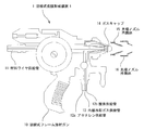
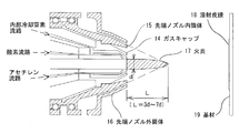
- FIG. It is a side view which shows the hot wire type film forming apparatus 1 It is an assembly enlarged view which shows the front-end
- FIG. It is a result of a combined cycle test. It is a result of a polarization measurement test. It is SEM sectional drawing of the sample which sprayed Al-Mg on the iron base material. It is a ferroxyl test result. It is an EBSP analysis figure. It is a metal-microscope sectional view of the sample which sprayed Al-Mg on the Al base material. It is a side view which shows the powder type film forming apparatus.
- a corrosion-resistant alloy sprayed coating is formed on a surface of a steel structure, a steel plate or the like by using a material mainly composed of Al-Mg and spraying with a coating forming apparatus which is a special spray gun.
- the used hot wire film forming apparatus 1 is shown in FIGS.
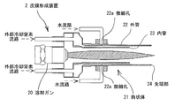
- the illustrated hot-wire-type film forming apparatus 1 includes a double nozzle comprising a front-end nozzle inner cylinder 15 and a front-end nozzle outer cylinder 16 at the front end of a frame-type spray gun 10 that supplies a material for forming a film with a wire. Is attached as a means for external cooling, from which jet gas (or mist) for externally cooling the flame or the like is emitted.
- the flame-type flame spray gun 10 has a material wire supply pipe 11 for supplying a material wire to be sprayed by a gas turbine (for example, one using nitrogen), an acetylene supply pipe 12a and an oxygen supply pipe as fuel. 12b and an internal cooling gas (for example, nitrogen) supply pipe 13 are connected.
- a gas cap 14 is provided at the front end of the hot-wire flame spray gun 10, from which a flame 17 and a molten material (the material wire is melted) are injected as shown in FIG. 2.
- the internal cooling gas is blown out from a position in contact with the inside of the gas cap 14 to cool the gas cap 14 and adjust the temperature of the flame 17.
- a gas cap 14 is fixed to the hot wire frame spray gun 10 near the front end thereof by, for example, screwing with a tip nozzle inner cylinder 15, and the tip nozzle outer cylinder 16 is fixed to the tip nozzle inner cylinder 15. It is attached to the hot wire frame spray gun 10 via
- Jet gas (or jet mist) for external cooling is supplied to the conical surface-like gap between the tip nozzle inner cylinder 15 and the tip nozzle outer cylinder 16, and the flame 17 is provided from the annular nozzle at the tip. It is ejected toward the front center line. From these points, the film forming apparatus 1 including the tip nozzle outer cylinder 16 and the like a) supply a corrosion-resistant alloy material with a wire, b) gradually from the outer peripheral portion of the tip nozzle toward the front (downstream side) central portion.
- the tip nozzle outer cylinder 16 shown in FIG. 1 blows out a jet gas (for example, nitrogen) or a jet mist (for example, water mist) as described above, whereby a flame 17 (see FIG. 2) is sprayed by the hot wire type flame spray gun 10. ), That is, in the melting region where the material wire is melted, the flame 17 can be separated from the outside air.
- a double nozzle made of stainless steel is used, and as described above, the tip nozzle inner cylinder 15 and the tip nozzle outer cylinder 16 are concentrically arranged to provide a gap therebetween, and the gap is formed by jet gas or jet mist. It is used as a flow path and as a spout for the same gas.
- the cooling gas flows between the double nozzles (the tip nozzle inner cylinder 15 and the tip nozzle outer cylinder 16), the temperature rise of the tip nozzle inner cylinder 15 and the like is suppressed.
- the gap between the double nozzles (tip nozzle inner cylinder 15 and tip nozzle outer cylinder 16) is provided toward the center line of the flame 17, and the jet gas or jet mist positively jets toward the center of the flame 17. It is supposed to be. Since the intersection of the jet gas or jet mist and the center line of the flame 17 is positioned forward from the jet port of the flame 17 by a distance 3 to 7 times the diameter of the flame 17, the jet gas or jet mist Has a function of quenching a sufficiently melted material at the tip of the flame 17 to refine its structure.
- the thermal spray coating 18 can be formed on the surface of the substrate 19 as shown on the right side of FIG. Since the flame 17 injected from the gas cap 14 of the hot wire flame spray gun 10 reaches the base material 19 surrounded by the jet gas or jet mist jetted by the tip nozzle outer cylinder 16 (the jet port), The amount of oxide present in the thermal spray coating 18 is small. Moreover, since it is rapidly cooled as described above, the crystal grain size of the thermal spray coating 18 is fine.
- a film forming apparatus 2 shown in FIG. 9 may be used.
- the film forming apparatus 2 has a cylindrical body 21 or the like attached to the front portion of the powder-type flame spray gun 20 that can also be called an external cooling device.
- a carrier gas for example, nitrogen
- a supply tube for acetylene and oxygen as fuel for example, and an internal cooling gas (for example, nitrogen)
- an internal cooling gas for example, nitrogen
- the cylindrical body 21 separates the flame from the outside air in the first half of the flame sprayed by the spray gun 20, that is, the melting region where the material powder is melted, and the jet mist or jet gas from the tip to the second half of the flame (front). It is for spewing out.
- a stainless steel double circular tube is used as the cylindrical body 21, and the outer tube 22 and the inner tube 23 are arranged concentrically to provide a gap therebetween.
- a jet mist or jet gas for externally cooling the flame and the molten material is supplied to the gap and ejected from the tip portion 24.
- a good Al-Mg film having excellent corrosion resistance can be formed on the surface of a steel structure. it can. Also, a good film can be formed on the surface of a base material made of Al or an Al alloy instead of a steel structure. This is because when the forming apparatus 1 or 2 is used, the molten material and the flame are cooled by the jet gas or the jet mist, so that the thermal influence on the substrate is small.
- Film formation by thermal spraying was performed by the following procedure. First, the surface of the steel plate (base material) is blasted with an alumina grid or a steel grid. Next, the Al—Mg material is sprayed onto the surface of the base material by the film forming apparatus 1 (melting wire type) or 2 (powder type). That is, the Al-Mg material is melted in a reducing atmosphere by adjusting the ratio of acetylene and oxygen, which are combustion gases, and by flowing a jet gas or jet mist along a double nozzle, A thermal spray coating is formed on the steel sheet (base material) with a cooling rate of about 1 million ° C. or more per second. Note that, unless otherwise noted, thermal spraying was performed under the conditions of Examples 1 to 3 as the present invention, and thermal spraying was performed under the conditions of Comparative Examples 1 and 2 as the prior art. Each condition is shown in Table 1.
- Example 1 and Comparative Example 1 were evaluated by conducting a corrosion acceleration test in which a cycle consisting of [° C./humidity 25% ⁇ 4 hours) ⁇ wet (high temperature) (50 ° C./humidity 98% ⁇ 2 hours) was repeated. In this test, the thickness of the sprayed coating on the test piece was 150 to 200 ⁇ m.
- Example 1 The white rust in Comparative Example 1 is an oxide of Al or Mg, suggesting that the coating deteriorates early. In Example 1, red rust or white rust even after 1,000 hours (125 cycles) has elapsed. It was good with no occurrence.
- CASS test Copper Accelerated Acetic Acid Salt Spray Test
- the spray test was carried out for 48 hours at 2 / h and compressed air pressure of 0.098 MPa.
- Example 1 and Comparative Example 1 were evaluated.
- the film thickness of the test piece was 250 to 300 ⁇ m.
- Table 2 below shows changes in surface condition and weight changes such as discoloration, stains, corrosion, surface deterioration, and peeling of the test pieces after the test.
- Al (OH) 3 corrosion products are produced by the dissolution reaction of Al, and the weight of the gel Al (OH) 3 is reduced by flowing down.
- Elemental analysis test Table 3 shows the analysis results obtained by ICP emission spectroscopy and inert gas melting method. From Table 3, there is no difference in the proportion of oxygen in the thermal spray material between Example 1 and Comparative Example 1, but in the thermal spray coating, Example 1 has an oxygen content of 0.2% by mass or less. It is 2% by mass or more. Therefore, it can be said that Example 1 can prevent oxidation of Al and Mg as compared with Comparative Example 1.
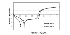
- Example 1 Electrochemical measurement test Polarization measurement was performed on each film of Example 1 and Comparative Example 1, and the results are shown in FIG.
- the natural potential of Example 1 was ⁇ 1.161V, and the natural potential of Comparative Example 1 was ⁇ 1.277V.
- the Al-Mg coating is less basic than steel and performs sacrificial protection.
- the natural potential of steel is ⁇ 0.4V to ⁇ 0.6V.
- Example 1 is more noble than Comparative Example 1, and since the anticorrosion current is suppressed from Comparative Example 1, the diffusion of oxygen in the Al-Mg sprayed coating is suppressed, and the anticorrosion life in salt water is improved. I can expect.
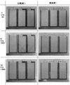
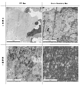
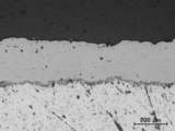
- Example 5 SEM images SEM observation was performed on Examples 1 to 3 and Comparative Example 1, and the SEM images are shown in FIG. In Examples 1 to 3, the porosity is 1% or less, and it can be confirmed that there are few pores and cracks compared to Comparative Example 1.
- pure water was added to 10 g of potassium hexacyanoferrate trihydrate, 10 g of potassium hexacyanoferrate, and 60 g of sodium chloride to prepare 1,000 ml, and a ferroxyl test was conducted in Example 1. If there is a defect reaching the substrate, blue spots can be observed, but Example 1 has no spots. The ferroxyl test results of Example 1 are shown in FIG.
- Example 1 EBSP analysis EBSP analysis (electron backscattering pattern) was performed on the films of Example 1 and Comparative Example 2, and the results are shown in FIG.
- the crystal grain size of Example 1 is 10 ⁇ m or less, and it can be confirmed that the grain size is very fine compared to Comparative Example 2.
Landscapes
- Chemical & Material Sciences (AREA)
- Engineering & Computer Science (AREA)
- Organic Chemistry (AREA)
- Materials Engineering (AREA)
- Mechanical Engineering (AREA)
- Metallurgy (AREA)
- Physics & Mathematics (AREA)
- Plasma & Fusion (AREA)
- Chemical Kinetics & Catalysis (AREA)
- Combustion & Propulsion (AREA)
- Wood Science & Technology (AREA)
- Life Sciences & Earth Sciences (AREA)
- Coating By Spraying Or Casting (AREA)
- Nozzles (AREA)
- Laminated Bodies (AREA)
Priority Applications (4)
| Application Number | Priority Date | Filing Date | Title |
|---|---|---|---|
| ES15742600T ES2797741T3 (es) | 2014-01-31 | 2015-01-27 | Recubrimiento pulverizado resistente a la corrosión y método para formar el mismo |
| US15/115,746 US10323153B2 (en) | 2014-01-31 | 2015-01-27 | Corrosion-resistant sprayed coating, method for forming same and spraying device for forming same |
| CN201580006682.XA CN106062236A (zh) | 2014-01-31 | 2015-01-27 | 耐腐蚀性热喷涂涂层、其形成方法及其形成用热喷涂装置 |
| EP15742600.8A EP3101151B1 (en) | 2014-01-31 | 2015-01-27 | Corrosion-resistant sprayed coating and method for forming same |
Applications Claiming Priority (2)
| Application Number | Priority Date | Filing Date | Title |
|---|---|---|---|
| JP2014-017943 | 2014-01-31 | ||
| JP2014017943A JP6367567B2 (ja) | 2014-01-31 | 2014-01-31 | 耐食性溶射皮膜、その形成方法およびその形成用溶射装置 |
Publications (1)
| Publication Number | Publication Date |
|---|---|
| WO2015115394A1 true WO2015115394A1 (ja) | 2015-08-06 |
Family
ID=53756967
Family Applications (1)
| Application Number | Title | Priority Date | Filing Date |
|---|---|---|---|
| PCT/JP2015/052111 Ceased WO2015115394A1 (ja) | 2014-01-31 | 2015-01-27 | 耐食性溶射皮膜、その形成方法およびその形成用溶射装置 |
Country Status (6)
| Country | Link |
|---|---|
| US (1) | US10323153B2 (enExample) |
| EP (1) | EP3101151B1 (enExample) |
| JP (1) | JP6367567B2 (enExample) |
| CN (1) | CN106062236A (enExample) |
| ES (1) | ES2797741T3 (enExample) |
| WO (1) | WO2015115394A1 (enExample) |
Cited By (1)
| Publication number | Priority date | Publication date | Assignee | Title |
|---|---|---|---|---|
| JP2017122253A (ja) * | 2016-01-05 | 2017-07-13 | 吉川工業株式会社 | 金属溶射皮膜及びその作製方法 |
Families Citing this family (18)
| Publication number | Priority date | Publication date | Assignee | Title |
|---|---|---|---|---|
| JP6367567B2 (ja) * | 2014-01-31 | 2018-08-01 | 吉川工業株式会社 | 耐食性溶射皮膜、その形成方法およびその形成用溶射装置 |
| JP2017008394A (ja) * | 2015-06-24 | 2017-01-12 | 有限会社エスエスシー | 低温溶射用hvaf溶射装置 |
| US10221654B2 (en) | 2015-08-26 | 2019-03-05 | Geodynamics, Inc. | Reverse flow arming and actuation apparatus and method |
| US10240446B2 (en) | 2015-08-26 | 2019-03-26 | Geodynamics, Inc. | Reverse flow seat forming apparatus and method |
| US10294752B2 (en) | 2015-08-26 | 2019-05-21 | Geodynamics, Inc. | Reverse flow catch-and-release tool and method |
| US9611721B2 (en) | 2015-08-26 | 2017-04-04 | Geodynamics, Inc. | Reverse flow sleeve actuation method |
| JP6924990B2 (ja) * | 2016-06-17 | 2021-08-25 | 吉川工業株式会社 | 溶射皮膜及び溶射皮膜部材 |
| JP2018141214A (ja) * | 2017-02-28 | 2018-09-13 | 吉川工業株式会社 | 耐水素脆性溶射皮膜及び耐水素脆性溶射皮膜部材 |
| WO2019082254A1 (ja) | 2017-10-24 | 2019-05-02 | 臼井国際産業株式会社 | 金属材およびその製造方法 |
| CN108480156A (zh) * | 2018-06-01 | 2018-09-04 | 深圳市金中瑞通讯技术有限公司 | 一种喷涂方法及喷枪 |
| RU196347U1 (ru) * | 2019-03-18 | 2020-02-26 | Сергей Львович Балдаев | Стальная нефтепромысловая труба |
| CN111471950A (zh) * | 2020-03-31 | 2020-07-31 | 中煤科工集团西安研究院有限公司 | 双金属配油套超音速热喷涂制造方法 |
| CN112852254A (zh) * | 2020-12-30 | 2021-05-28 | 镇江市润发铝业有限公司 | 一种高强耐腐蚀型复合铝箔及其制备方法 |
| KR102729064B1 (ko) * | 2023-01-10 | 2024-11-13 | (주)코미코 | 대기 플라즈마 용사법에 의한 고밀도의 이트리아 피막의 제조 방법 및 이를 이용하여 제조된 이트리아 용사 피막 |
| US12326203B2 (en) | 2023-06-30 | 2025-06-10 | Halliburton Energy Services, Inc. | Downhole tool with crack compliant seal and mechanical strengthening feature at a joint thereof |
| US12326046B2 (en) | 2023-06-30 | 2025-06-10 | Halliburton Energy Services, Inc. | Downhole tool with crack compliant seal and high yield strength weld positioned at a joint thereof |
| CN118207480A (zh) * | 2024-04-17 | 2024-06-18 | 南通市嘉业机械制造有限公司 | 一种耐腐蚀无缝钢管穿孔顶头及其制备工艺 |
| CN119663160A (zh) * | 2024-12-05 | 2025-03-21 | 国网山东省电力公司电力科学研究院 | 一种架空输电线路连接金具制备方法及连接金具 |
Citations (8)
| Publication number | Priority date | Publication date | Assignee | Title |
|---|---|---|---|---|
| JPH06330263A (ja) * | 1993-05-24 | 1994-11-29 | Sumitomo Light Metal Ind Ltd | 高靭性Al−Si系合金の製造方法 |
| JPH101766A (ja) | 1996-06-11 | 1998-01-06 | Nippon Steel Corp | 耐食性及び耐傷付き性に優れた溶射皮膜 |
| JP2001247953A (ja) | 2000-03-08 | 2001-09-14 | Tocalo Co Ltd | 耐食性に優れた溶射被覆部材およびその製造方法 |
| JP2002053943A (ja) * | 2000-08-07 | 2002-02-19 | Toshiba Corp | 耐食コーティング部材 |
| JP2007131952A (ja) * | 2004-03-25 | 2007-05-31 | Akihisa Inoue | 金属ガラス積層体 |
| JP2008043869A (ja) * | 2006-08-14 | 2008-02-28 | Nakayama Steel Works Ltd | 過冷却液相金属皮膜の形成用溶射装置 |
| JP2010022895A (ja) * | 2008-07-15 | 2010-02-04 | Nakayama Steel Works Ltd | アモルファス皮膜の形成装置および形成方法 |
| WO2013105613A1 (ja) * | 2012-01-13 | 2013-07-18 | 株式会社中山製鋼所 | アモルファス皮膜の形成装置および形成方法 |
Family Cites Families (36)
| Publication number | Priority date | Publication date | Assignee | Title |
|---|---|---|---|---|
| US4593007A (en) * | 1984-12-06 | 1986-06-03 | The Perkin-Elmer Corporation | Aluminum and silica clad refractory oxide thermal spray powder |
| JP2826220B2 (ja) * | 1991-09-19 | 1998-11-18 | トーカロ株式会社 | 溶融亜鉛浴用部材 |
| US20030088980A1 (en) * | 1993-11-01 | 2003-05-15 | Arnold James E. | Method for correcting defects in a workpiece |
| DE69716336T2 (de) * | 1996-05-08 | 2003-02-20 | Denki Kagaku Kogyo K.K., Tokio/Tokyo | Aluminium-Chrom-Legierung, Verfahren zu ihrer Herstellung, und ihre Anwendungen |
| BR9714974A (pt) * | 1996-12-23 | 2000-10-03 | James E Arnold | Método de tratamento dos componentes metálicos |
| US5820939A (en) * | 1997-03-31 | 1998-10-13 | Ford Global Technologies, Inc. | Method of thermally spraying metallic coatings using flux cored wire |
| DE19733204B4 (de) * | 1997-08-01 | 2005-06-09 | Daimlerchrysler Ag | Beschichtung aus einer übereutektischen Aluminium/Silizium Legierung, Spritzpulver zu deren Herstellung sowie deren Verwendung |
| US6231969B1 (en) * | 1997-08-11 | 2001-05-15 | Drexel University | Corrosion, oxidation and/or wear-resistant coatings |
| JP4648541B2 (ja) * | 1998-03-14 | 2011-03-09 | ダナ・コーポレイション | すべり軸受のライニングの形成方法 |
| USH1869H (en) * | 1998-12-18 | 2000-10-03 | Caterpillar Inc. | Valve train components having an oxidation and corrosion-resistant thermal spray coating |
| US6372299B1 (en) * | 1999-09-28 | 2002-04-16 | General Electric Company | Method for improving the oxidation-resistance of metal substrates coated with thermal barrier coatings |
| US20020073982A1 (en) * | 2000-12-16 | 2002-06-20 | Shaikh Furqan Zafar | Gas-dynamic cold spray lining for aluminum engine block cylinders |
| JP4036387B2 (ja) * | 2001-05-11 | 2008-01-23 | 日鐵溶接工業株式会社 | レーザアシスト高速フレーム溶射法および装置 |
| US20030049485A1 (en) * | 2001-09-06 | 2003-03-13 | Brupbacher John M. | Corrosion control coatings |
| ES2586586T3 (es) | 2004-03-25 | 2016-10-17 | Tohoku Techno Arch Co., Ltd. | Laminados de vidrio metálico, procedimientos de producción y aplicaciones de los mismos |
| FR2877015B1 (fr) * | 2004-10-21 | 2007-10-26 | Commissariat Energie Atomique | Revetement nanostructure et procede de revetement. |
| KR100915722B1 (ko) * | 2005-06-23 | 2009-09-04 | 도쿄엘렉트론가부시키가이샤 | 반도체 처리 장치용의 구성 부재 및 그 제조 방법, 및반도체 처리 장치 |
| EP1762639A1 (en) * | 2005-09-13 | 2007-03-14 | Kabushiki Kaisha Kobe Seiko Sho (Kobe Steel, Ltd.) | Heat transfer tube for LNG vaporizer, its production method, and LNG vaporizer using such heat transfer tubes |
| DE102005047037A1 (de) * | 2005-09-30 | 2007-04-19 | BAM Bundesanstalt für Materialforschung und -prüfung | Motorische Gleitpaarung aus einer Aluminiumbasislegierung |
| WO2008020585A1 (en) | 2006-08-14 | 2008-02-21 | Nakayama Steel Works, Ltd. | Method and apparatus for forming amorphous coating film |
| JP5190238B2 (ja) * | 2006-09-28 | 2013-04-24 | 新日鐵住金株式会社 | 高耐食性防錆塗料、高耐食性鉄鋼材料及び鋼構造物 |
| US20110159138A1 (en) * | 2007-01-08 | 2011-06-30 | Garrtech Inc. | Blow mold for molding a container |
| US7904491B2 (en) * | 2007-07-18 | 2011-03-08 | Sap Ag | Data mapping and import system |
| DE102008026101B4 (de) * | 2008-05-30 | 2010-02-18 | Fraunhofer-Gesellschaft zur Förderung der angewandten Forschung e.V. | Thermisch gespritzte Al2O3-Schichten mit einem hohen Korundgehalt ohne eigenschaftsmindernde Zusätze und Verfahren zu ihrer Herstellung |
| US8313557B2 (en) * | 2008-07-30 | 2012-11-20 | The United States Of America, As Represented By The Secretary Of The Navy | Recovery of [CO2]T from seawater/aqueous bicarbonate systems using a multi-layer gas permeable membrane |
| US9611522B2 (en) * | 2009-05-06 | 2017-04-04 | United Technologies Corporation | Spray deposition of L12 aluminum alloys |
| US20110064963A1 (en) * | 2009-09-17 | 2011-03-17 | Justin Lee Cheney | Thermal spray processes and alloys for use in same |
| KR101476897B1 (ko) * | 2010-01-13 | 2014-12-26 | 가부시키가이샤 나카야마 아몰퍼스 | 비결정질 피막의 형성장치 및 방법 |
| CN102906298B (zh) * | 2010-05-24 | 2014-12-03 | 日铁住金表面硬化株式会社 | 热喷涂件以及热喷涂件的热喷涂方法 |
| US9194039B2 (en) * | 2011-03-15 | 2015-11-24 | Directed Vapor Technologies International | Method for applying aluminum alloy coatings for corrosion protection of steel |
| JP5973790B2 (ja) * | 2012-05-28 | 2016-08-23 | 株式会社中山アモルファス | 耐食性、導電性、成形性に優れた薄板およびその製造方法 |
| KR101519709B1 (ko) * | 2013-03-05 | 2015-05-12 | 기아자동차주식회사 | 고속화염용사 코팅법과 플라즈마 이온 질화법를 이용한 금형의 보정 및 재생 방법 |
| WO2015053948A1 (en) * | 2013-10-09 | 2015-04-16 | United Technologies Corporation | Aluminum alloy coating with rare earth and transition metal corrosion inhibitors |
| US10392685B2 (en) * | 2013-10-31 | 2019-08-27 | The Regents Of The University Of Michigan | Composite metal alloy material |
| JP6367567B2 (ja) * | 2014-01-31 | 2018-08-01 | 吉川工業株式会社 | 耐食性溶射皮膜、その形成方法およびその形成用溶射装置 |
| CN107083502B (zh) * | 2016-02-12 | 2023-10-13 | 肯纳金属公司 | 耐磨且耐蚀的钴基合金粉末及其施加方法 |
-
2014
- 2014-01-31 JP JP2014017943A patent/JP6367567B2/ja active Active
-
2015
- 2015-01-27 ES ES15742600T patent/ES2797741T3/es active Active
- 2015-01-27 WO PCT/JP2015/052111 patent/WO2015115394A1/ja not_active Ceased
- 2015-01-27 US US15/115,746 patent/US10323153B2/en active Active
- 2015-01-27 CN CN201580006682.XA patent/CN106062236A/zh active Pending
- 2015-01-27 EP EP15742600.8A patent/EP3101151B1/en active Active
Patent Citations (8)
| Publication number | Priority date | Publication date | Assignee | Title |
|---|---|---|---|---|
| JPH06330263A (ja) * | 1993-05-24 | 1994-11-29 | Sumitomo Light Metal Ind Ltd | 高靭性Al−Si系合金の製造方法 |
| JPH101766A (ja) | 1996-06-11 | 1998-01-06 | Nippon Steel Corp | 耐食性及び耐傷付き性に優れた溶射皮膜 |
| JP2001247953A (ja) | 2000-03-08 | 2001-09-14 | Tocalo Co Ltd | 耐食性に優れた溶射被覆部材およびその製造方法 |
| JP2002053943A (ja) * | 2000-08-07 | 2002-02-19 | Toshiba Corp | 耐食コーティング部材 |
| JP2007131952A (ja) * | 2004-03-25 | 2007-05-31 | Akihisa Inoue | 金属ガラス積層体 |
| JP2008043869A (ja) * | 2006-08-14 | 2008-02-28 | Nakayama Steel Works Ltd | 過冷却液相金属皮膜の形成用溶射装置 |
| JP2010022895A (ja) * | 2008-07-15 | 2010-02-04 | Nakayama Steel Works Ltd | アモルファス皮膜の形成装置および形成方法 |
| WO2013105613A1 (ja) * | 2012-01-13 | 2013-07-18 | 株式会社中山製鋼所 | アモルファス皮膜の形成装置および形成方法 |
Cited By (1)
| Publication number | Priority date | Publication date | Assignee | Title |
|---|---|---|---|---|
| JP2017122253A (ja) * | 2016-01-05 | 2017-07-13 | 吉川工業株式会社 | 金属溶射皮膜及びその作製方法 |
Also Published As
| Publication number | Publication date |
|---|---|
| EP3101151A4 (en) | 2017-11-01 |
| US20170015838A1 (en) | 2017-01-19 |
| CN106062236A (zh) | 2016-10-26 |
| EP3101151B1 (en) | 2020-06-03 |
| US10323153B2 (en) | 2019-06-18 |
| ES2797741T3 (es) | 2020-12-03 |
| EP3101151A1 (en) | 2016-12-07 |
| JP2015145516A (ja) | 2015-08-13 |
| JP6367567B2 (ja) | 2018-08-01 |
Similar Documents
| Publication | Publication Date | Title |
|---|---|---|
| JP6367567B2 (ja) | 耐食性溶射皮膜、その形成方法およびその形成用溶射装置 | |
| Tang et al. | Effects of surface oxidation during HVOF processing on the primary stage oxidation of a CoNiCrAlY coating | |
| CN102906298B (zh) | 热喷涂件以及热喷涂件的热喷涂方法 | |
| CN103801893B (zh) | 一种用于船舶螺旋桨腐蚀修复与长效防护的方法 | |
| JP2018506644A (ja) | 溶接性及び加工部耐食性に優れた亜鉛合金めっき鋼材及びその製造方法 | |
| US20130216722A1 (en) | Coating Compositions, Applications Thereof, and Methods of Forming | |
| JP3612568B2 (ja) | Hvof溶射ガンによる金属皮膜形成方法と溶射装置 | |
| WO2009072318A1 (ja) | 黒色酸化イットリウム溶射皮膜の形成方法および黒色酸化イットリウム溶射皮膜被覆部材 | |
| CN109440052A (zh) | 一种大气等离子体喷涂氧化钇涂层的复合涂层制备方法 | |
| Park et al. | Electrochemical characteristics in seawater for cold thermal spray-coated Al–Mg alloy layer | |
| JP6500136B2 (ja) | 耐食性溶射皮膜、その形成方法およびその形成用溶射装置 | |
| CN106567027A (zh) | 一种金属管道镍基复合耐蚀涂层及其制备方法 | |
| JP6594209B2 (ja) | 金属溶射皮膜の作製方法 | |
| RU2489512C2 (ru) | Способ антикоррозионной обработки детали путем осаждения слоя циркония и/или циркониевого сплава | |
| CN108842128A (zh) | 一种含陶瓷颗粒铝基复合粉芯丝材及涂层的制备方法 | |
| JP5098109B2 (ja) | 皮膜形成方法 | |
| JP6418854B2 (ja) | 水反応性Al合金溶射膜の製造方法 | |
| Kawakita et al. | Corrosion resistance of HastelloyC coatings formed by an improved HVOF thermal spraying process | |
| TW201418376A (zh) | 防止海洋生物污損的複合塗層及其噴塗方法 | |
| US20130216862A1 (en) | Coating Compositions, Applications Thereof, and Methods of Forming | |
| JP5385754B2 (ja) | 熱交換部材 | |
| Kawakita et al. | Oscillational corrosion potential of HastelloyC coatings fabricated by GS-HVOF spraying | |
| JP4172653B2 (ja) | 耐海水防食方法 | |
| Dong et al. | Long-Term Corrosion Behavior of Atmospheric Plasma Sprayed NiCr Alloy Containing Boron in 3.5 wt.% NaCl Solution | |
| Kawakita et al. | Oxidation restriction of in-flight particles upon GS-HVOF spraying by nitrogen addition to combustion gas |
Legal Events
| Date | Code | Title | Description |
|---|---|---|---|
| DPE1 | Request for preliminary examination filed after expiration of 19th month from priority date (pct application filed from 20040101) | ||
| NENP | Non-entry into the national phase |
Ref country code: DE |
|
| WWE | Wipo information: entry into national phase |
Ref document number: 15115746 Country of ref document: US |
|
| REEP | Request for entry into the european phase |
Ref document number: 2015742600 Country of ref document: EP |
|
| WWE | Wipo information: entry into national phase |
Ref document number: 2015742600 Country of ref document: EP |
|
| 121 | Ep: the epo has been informed by wipo that ep was designated in this application |
Ref document number: 15742600 Country of ref document: EP Kind code of ref document: A1 |