USH1869H - Valve train components having an oxidation and corrosion-resistant thermal spray coating - Google Patents
Valve train components having an oxidation and corrosion-resistant thermal spray coating Download PDFInfo
- Publication number
- USH1869H USH1869H US09/216,160 US21616098A USH1869H US H1869 H USH1869 H US H1869H US 21616098 A US21616098 A US 21616098A US H1869 H USH1869 H US H1869H
- Authority
- US
- United States
- Prior art keywords
- valve train
- engine valve
- train component
- depositing
- making
- Prior art date
- Legal status (The legal status is an assumption and is not a legal conclusion. Google has not performed a legal analysis and makes no representation as to the accuracy of the status listed.)
- Abandoned
Links
- 238000005260 corrosion Methods 0.000 title claims abstract description 16
- 230000007797 corrosion Effects 0.000 title claims abstract description 16
- 230000003647 oxidation Effects 0.000 title claims abstract description 14
- 238000007254 oxidation reaction Methods 0.000 title claims abstract description 14
- 238000005507 spraying Methods 0.000 title abstract 2
- 238000000576 coating method Methods 0.000 claims abstract description 39
- 239000011248 coating agent Substances 0.000 claims abstract description 37
- 239000000463 material Substances 0.000 claims description 25
- 238000000151 deposition Methods 0.000 claims description 23
- 238000004519 manufacturing process Methods 0.000 claims description 19
- PXHVJJICTQNCMI-UHFFFAOYSA-N Nickel Chemical compound [Ni] PXHVJJICTQNCMI-UHFFFAOYSA-N 0.000 claims description 15
- 239000011651 chromium Substances 0.000 claims description 13
- 229910052804 chromium Inorganic materials 0.000 claims description 12
- 229910052782 aluminium Inorganic materials 0.000 claims description 10
- 238000002485 combustion reaction Methods 0.000 claims description 10
- 229910052727 yttrium Inorganic materials 0.000 claims description 10
- 239000011573 trace mineral Substances 0.000 claims description 9
- 235000013619 trace mineral Nutrition 0.000 claims description 9
- 239000000203 mixture Substances 0.000 claims description 8
- VYZAMTAEIAYCRO-UHFFFAOYSA-N Chromium Chemical compound [Cr] VYZAMTAEIAYCRO-UHFFFAOYSA-N 0.000 claims description 6
- 238000000034 method Methods 0.000 claims description 6
- 229910052759 nickel Inorganic materials 0.000 claims description 6
- 239000002245 particle Substances 0.000 claims description 6
- 239000007921 spray Substances 0.000 claims description 6
- 238000001816 cooling Methods 0.000 claims description 5
- 230000008021 deposition Effects 0.000 claims description 5
- 239000000843 powder Substances 0.000 claims description 5
- XAGFODPZIPBFFR-UHFFFAOYSA-N aluminium Chemical compound [Al] XAGFODPZIPBFFR-UHFFFAOYSA-N 0.000 claims description 4
- 238000005422 blasting Methods 0.000 claims description 4
- 239000002737 fuel gas Substances 0.000 claims description 4
- 238000000227 grinding Methods 0.000 claims description 4
- VWQVUPCCIRVNHF-UHFFFAOYSA-N yttrium atom Chemical compound [Y] VWQVUPCCIRVNHF-UHFFFAOYSA-N 0.000 claims description 4
- QVGXLLKOCUKJST-UHFFFAOYSA-N atomic oxygen Chemical compound [O] QVGXLLKOCUKJST-UHFFFAOYSA-N 0.000 claims description 3
- 239000001301 oxygen Substances 0.000 claims description 3
- 229910052760 oxygen Inorganic materials 0.000 claims description 3
- 238000002156 mixing Methods 0.000 claims 1
- 239000000446 fuel Substances 0.000 abstract description 4
- 239000007789 gas Substances 0.000 description 5
- 229910001120 nichrome Inorganic materials 0.000 description 5
- 239000011253 protective coating Substances 0.000 description 5
- 229910010038 TiAl Inorganic materials 0.000 description 4
- 238000005336 cracking Methods 0.000 description 4
- 238000005552 hardfacing Methods 0.000 description 3
- IJGRMHOSHXDMSA-UHFFFAOYSA-N Atomic nitrogen Chemical compound N#N IJGRMHOSHXDMSA-UHFFFAOYSA-N 0.000 description 2
- 238000005238 degreasing Methods 0.000 description 2
- OKTJSMMVPCPJKN-UHFFFAOYSA-N Carbon Chemical compound [C] OKTJSMMVPCPJKN-UHFFFAOYSA-N 0.000 description 1
- VMMPWTXGBPAOJS-UHFFFAOYSA-N [O].C=CC.[O] Chemical group [O].C=CC.[O] VMMPWTXGBPAOJS-UHFFFAOYSA-N 0.000 description 1
- 239000000654 additive Substances 0.000 description 1
- 230000015572 biosynthetic process Effects 0.000 description 1
- 229910052799 carbon Inorganic materials 0.000 description 1
- 125000004122 cyclic group Chemical group 0.000 description 1
- 239000002283 diesel fuel Substances 0.000 description 1
- 238000009826 distribution Methods 0.000 description 1
- 230000000694 effects Effects 0.000 description 1
- 230000002708 enhancing effect Effects 0.000 description 1
- 230000003628 erosive effect Effects 0.000 description 1
- 230000000977 initiatory effect Effects 0.000 description 1
- 238000005461 lubrication Methods 0.000 description 1
- 229910052751 metal Inorganic materials 0.000 description 1
- 239000002184 metal Substances 0.000 description 1
- 150000002739 metals Chemical class 0.000 description 1
- 229910001235 nimonic Inorganic materials 0.000 description 1
- 229910052757 nitrogen Inorganic materials 0.000 description 1
- TWNQGVIAIRXVLR-UHFFFAOYSA-N oxo(oxoalumanyloxy)alumane Chemical compound O=[Al]O[Al]=O TWNQGVIAIRXVLR-UHFFFAOYSA-N 0.000 description 1
- QQONPFPTGQHPMA-UHFFFAOYSA-N propylene Natural products CC=C QQONPFPTGQHPMA-UHFFFAOYSA-N 0.000 description 1
- 125000004805 propylene group Chemical group [H]C([H])([H])C([H])([*:1])C([H])([H])[*:2] 0.000 description 1
- 230000003252 repetitive effect Effects 0.000 description 1
- 238000007789 sealing Methods 0.000 description 1
- 238000000926 separation method Methods 0.000 description 1
- 239000000758 substrate Substances 0.000 description 1
Images
Classifications
-
- F—MECHANICAL ENGINEERING; LIGHTING; HEATING; WEAPONS; BLASTING
- F01—MACHINES OR ENGINES IN GENERAL; ENGINE PLANTS IN GENERAL; STEAM ENGINES
- F01L—CYCLICALLY OPERATING VALVES FOR MACHINES OR ENGINES
- F01L3/00—Lift-valve, i.e. cut-off apparatus with closure members having at least a component of their opening and closing motion perpendicular to the closing faces; Parts or accessories thereof
- F01L3/02—Selecting particular materials for valve-members or valve-seats; Valve-members or valve-seats composed of two or more materials
- F01L3/04—Coated valve members or valve-seats
-
- F—MECHANICAL ENGINEERING; LIGHTING; HEATING; WEAPONS; BLASTING
- F01—MACHINES OR ENGINES IN GENERAL; ENGINE PLANTS IN GENERAL; STEAM ENGINES
- F01L—CYCLICALLY OPERATING VALVES FOR MACHINES OR ENGINES
- F01L3/00—Lift-valve, i.e. cut-off apparatus with closure members having at least a component of their opening and closing motion perpendicular to the closing faces; Parts or accessories thereof
- F01L3/02—Selecting particular materials for valve-members or valve-seats; Valve-members or valve-seats composed of two or more materials
Definitions
- This invention relates generally to the field of internal combustion engines, and more particularly to improved wear resistance of valve train components.
- Engine exhaust valves control the intake of an air-fuel mixture and the discharge of spent gas in the combustion chamber.
- Each engine valve includes a valve head and a valve stem extending therefrom.
- the valve head is located within the combustion chamber. Cycles of tight engagement and separation are repeated between a valve seat insert snuggly fitted in a cylinder head and a contact face on the valve head.
- the engine valve is required to be resistant to heat, corrosion, and wear because it is exposed to elevated temperatures of 700° C. to 800° C. in a combustion chamber and subjected to repetitive collision against the valve seat insert.
- today's engines are pushed to operate at higher temperatures, higher peak cylinder pressures, more corrosive environments and highly variable fuel types and quality.
- the present invention is directed to overcoming one or more of the problems set forth above.
- a method of making an engine valve train component having a protective coating comprising the steps of: grit blasting the face of the valve component; selecting an oxidation and corrosion-resistant coating material having the general formula MCrAlY; depositing the oxidation and corrosion-resistant coating material onto the face of the valve component; cooling the valve component during the deposition; thereafter grinding the face to finish dimensions; and thereby making an engine valve train component with an oxidation and corrosion-resistant coating on its face.
- an engine valve train component having a protective coating material including: an oxidation and corrosion-resistant, thermal spray deposited coating at the face of the valve component; and said coating having the general formula MCrAlY.
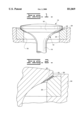
- FIG. 1 is a view, partly elevational and partly sectional, of an engine valve including a valve head seated in a valve seat;
- FIG. 2 is a fragmentary cross-section on a larger scale than FIG. 1 and showing the protective coating on a contact face and a valve seat face.
- An engine valve generally designated 10, includes a head 12 which has a stem 14 and a contact face 16.
- a valve opening 18 is formed by a valve seat insert 20 fitted into the engine block 24.
- the insert 20 has a valve seat face 22 against which the contact face 16 fits in gas-sealing engagement.
- a relatively thin protective coating 30 is on either face 16 or 22, or both.
- the protective coating 30 is an oxidation and corrosion-resistant coating. This coating is thermal spray deposited via a process of: degreasing the valve component 12 or 20; grit blasting a face 16 or 22 at about 100 psi using aluminum oxide having a size less than about 1.7mm; subsequently degreasing the valve component; depositing an oxidation and corrosion-resistant coating 30 at least about 0.015" thick onto the face 16 or 22; cooling the valve component 12 or 20 during the deposition using auxiliary air; thereafter finish grinding the coating 30 of the valve component to finish dimensions with about 0.010" coating thickness.
- High Velocity Oxygen Fuel This is a combustion process where oxygen is mixed with a fuel gas in a specified ratio and ignited.
- the exhaust gas is accelerated toward a substrate using a converging/diverging nozzle, achieving velocities of 4500 ft/s.
- Powder metals or cermets with a particle size distribution from about 11-44 ⁇ m are injected generally axially into the gas stream, become molten and are propelled toward the contact face 16 and/or the valve seat face 22.
- Valve seat faces 22 are sprayed at around a 90 degree angle to a thickness of approximately 0.015-0.020".
- the high particle velocities contribute to the high mechanical bond strengths and high densities of HVOF coatings.
- the valve component 10 and/or 20 is cooled with auxiliary air, and thereafter the coating 30 is finish ground to print dimensions, with approximately 0.010" final coating thickness, as described above.
- Table I indicates several applicable materials for coating 30.
- HVOF processing parameters for Sulzer Metco HVOF equipment are included in Table II.
- Table III indicates corrosion test results compared to current production valve materials.
- the material selected for the coating 30 has the general formula MCrAlY.
- the NiCrAlY-A generally is about 76.17% by weight nickel; 16.80% by weight chromium; 6.25% by weight aluminum; and 0.68% by weight yttrium.
- NiCrAlY-B generally is about 56.69% by weight nickel; 31.07% by weight chromium; 11.26% by weight aluminum; 0.01% by weight carbon; and 0.71% by weight yttrium.
Landscapes
- Engineering & Computer Science (AREA)
- Mechanical Engineering (AREA)
- General Engineering & Computer Science (AREA)
- Other Surface Treatments For Metallic Materials (AREA)
Abstract
Today's engines are pushed to operate at higher temperatures, higher peak cylinder pressures, in more corrosive environments and with highly variable fuel types and qualities. A solution to guttering is an oxidation and corrosion-resistant coating with a general turn MCrAlY applied to the face of the engine valve train components by thermal spray coating.
Description
This invention relates generally to the field of internal combustion engines, and more particularly to improved wear resistance of valve train components.
Engine exhaust valves control the intake of an air-fuel mixture and the discharge of spent gas in the combustion chamber. Each engine valve includes a valve head and a valve stem extending therefrom. The valve head is located within the combustion chamber. Cycles of tight engagement and separation are repeated between a valve seat insert snuggly fitted in a cylinder head and a contact face on the valve head. The engine valve is required to be resistant to heat, corrosion, and wear because it is exposed to elevated temperatures of 700° C. to 800° C. in a combustion chamber and subjected to repetitive collision against the valve seat insert. Furthermore, today's engines are pushed to operate at higher temperatures, higher peak cylinder pressures, more corrosive environments and highly variable fuel types and quality.
Observation of the failed valves has shown that failure appears to result from two separate and distinct modes: (i) corrosive attack that leads to guttering and (ii) radial cracking along the valve face. Guttering tends to predominate in engines burning diesel fuel; whereas radial cracking is generally observed in gas-burning engines, where engine temperatures are typically higher. Guttering in diesel engines is primarily an oxidation phenomenon along the contact face that is accelerated by the presence of deposits. These deposits, which strongly adhere to the contact face, are formed by the combustion of additives in a lubrication enhancing oil. The oxidized region is inherently brittle and erodes away during repeated cyclic loading during operation. The erosion process accelerates in an avalanche effect until engine performance degrades to the point of failure.
The root cause of radial cracking of valves in gas-burning engines appears to be related in part to the residual stresses associated with a hardfacing weldment. The higher the operating temperatures vis-a-vis diesel engines suggest that high-temperature fatigue initiating at the hardfacing/head interface could also play a role.
The wear resistance problems of engine exhaust valves described above may be addressed by hardfacing or manufacturing engine exhaust valves with a base material that is comprised of the components of the present invention. However, such alternatives would be very expensive.
The present invention is directed to overcoming one or more of the problems set forth above.
In accordance with the present invention there is provided a method of making an engine valve train component having a protective coating, comprising the steps of: grit blasting the face of the valve component; selecting an oxidation and corrosion-resistant coating material having the general formula MCrAlY; depositing the oxidation and corrosion-resistant coating material onto the face of the valve component; cooling the valve component during the deposition; thereafter grinding the face to finish dimensions; and thereby making an engine valve train component with an oxidation and corrosion-resistant coating on its face.
In accordance with another aspect of the invention there is provided an engine valve train component having a protective coating material including: an oxidation and corrosion-resistant, thermal spray deposited coating at the face of the valve component; and said coating having the general formula MCrAlY.
FIG. 1 is a view, partly elevational and partly sectional, of an engine valve including a valve head seated in a valve seat; and
FIG. 2 is a fragmentary cross-section on a larger scale than FIG. 1 and showing the protective coating on a contact face and a valve seat face.
An engine valve, generally designated 10, includes a head 12 which has a stem 14 and a contact face 16. A valve opening 18 is formed by a valve seat insert 20 fitted into the engine block 24. The insert 20 has a valve seat face 22 against which the contact face 16 fits in gas-sealing engagement. A relatively thin protective coating 30 is on either face 16 or 22, or both.
The protective coating 30 is an oxidation and corrosion-resistant coating. This coating is thermal spray deposited via a process of: degreasing the valve component 12 or 20; grit blasting a face 16 or 22 at about 100 psi using aluminum oxide having a size less than about 1.7mm; subsequently degreasing the valve component; depositing an oxidation and corrosion-resistant coating 30 at least about 0.015" thick onto the face 16 or 22; cooling the valve component 12 or 20 during the deposition using auxiliary air; thereafter finish grinding the coating 30 of the valve component to finish dimensions with about 0.010" coating thickness.
To achieve low porosity, the deposition is by a high particle velocity spray device. One such device is generically termed High Velocity Oxygen Fuel (HVOF). This is a combustion process where oxygen is mixed with a fuel gas in a specified ratio and ignited. In this embodiment, the exhaust gas is accelerated toward a substrate using a converging/diverging nozzle, achieving velocities of 4500 ft/s. Powder metals or cermets with a particle size distribution from about 11-44 μm are injected generally axially into the gas stream, become molten and are propelled toward the contact face 16 and/or the valve seat face 22. Valve seat faces 22 are sprayed at around a 90 degree angle to a thickness of approximately 0.015-0.020". The high particle velocities contribute to the high mechanical bond strengths and high densities of HVOF coatings. During the process, the valve component 10 and/or 20 is cooled with auxiliary air, and thereafter the coating 30 is finish ground to print dimensions, with approximately 0.010" final coating thickness, as described above.
Table I indicates several applicable materials for coating 30.
                                  TABLE I
__________________________________________________________________________
Material
       Mftr Name
               Fe Ni Cr Ti Al C  Nb Y  Co
__________________________________________________________________________
NiCrAlY--B
       Amdry 961
               -- 76.17
                     16.8
                        -- 6.25
                              -- -- 0.68
                                       --
NiCrAlY--A
        Amdry 964
                    56.69
                        31.07
                         --
                            11.26
                                 --.01
                                      0.71
                                            --
CrC--NiCr
         Diamaloy 3006
                 --
                    41
                            --
                               7      ----
                                        --
CrC--NiCr
         Diamalloy 3007
                --
                    16
                            --
                                      ---
                                            --
TiAl          TiAl
                    -- --
                     2        47
                                 --
                                 2          --
FrCrAlY
                70
                                           25
CoCrAlY
                                             73.5
NiCoCrAlY
                     18 46.2
                                             23
__________________________________________________________________________
HVOF processing parameters for Sulzer Metco HVOF equipment are included in Table II.
                                  TABLE II
__________________________________________________________________________
      Oxygen
          Oxygen
               Propylene
                    Propylene
                         Air Air Flow
                                  Nitrogen
                                       Powder
           Flow Rate
                 Presure
                       Flow Rate
                         Pressure
                              Rate
                                          Feed Rate
Material
         (PSI)
           (SCFH)
                    (PSI)
                       (SCFH)
                         (PSI)
                                (SCFH)
                                      (PSI)
                                           (3/min)
__________________________________________________________________________
CrC--NiCr
      150 606  100  167  75  805  175  38
NiCrAlY
          150
           577         167
                          75    631
                                           70
TiAl                                           20
__________________________________________________________________________
Table III indicates corrosion test results compared to current production valve materials.
              TABLE III
______________________________________
Material        Thickness of Corroded Region
______________________________________
Nimonic 80A     100 μm
Eatonite 6            15 μm
CrC--NiCr (Diamalloy 3006)
                  100 μm
TiAl                   coating spalled during cooling
NiCrAlY--A            no evidence of corrosion except small
                       localized 10 μm region
NiCrAlY--B            no evidence of corrosion except small
                       localized 10 μm regions
CrC--NiCr             entire thickness of coating - 350
______________________________________
                μm
From the above results the material selected for the coating 30 has the general formula MCrAlY. In one composition the NiCrAlY-A, generally is about 76.17% by weight nickel; 16.80% by weight chromium; 6.25% by weight aluminum; and 0.68% by weight yttrium. In another composition, NiCrAlY-B generally is about 56.69% by weight nickel; 31.07% by weight chromium; 11.26% by weight aluminum; 0.01% by weight carbon; and 0.71% by weight yttrium. Of course, there may be trace elements.
The above-described corrosion and oxidation-resistant coatings possess wear characteristics to withstand the demanding conditions present during engine operation. This precludes the guttering problem which is related to oxidation followed by micro cracking. While it is not known how guttering occurs, one possible explanation is that the exhaust gases erode the microcracks and form gas paths. Another possibility results from deposit formation on the face and subsequent spallation which removes some of the valve face material.
While preferred steps and materials have herein been described, this has been done by way of illustration and not limitation, and the invention should not be limited except as may be required by the scope of the appended claims.
Claims (20)
1. A method of making an engine valve train component for an internal combustion engine, comprising the steps of:
grit blasting a face of the engine valve train component;
depositing an oxidation and corrosion-resistant coating material having the general form MCrAlY onto the face of the engine valve train component;
cooling the engine valve train component during the deposition;
grinding the face to finish dimensions.
2. The method of making an engine valve train component as set forth in claim 1, wherein the step of depositing includes depositing said coating material having about 17-31% by weight chromium.
3. The method of making an engine valve train as set forth in claim 1, wherein the step of depositing includes depositing said coating material having about 57-76% by weight nickel; about 17-31% by weight chromium; and the remainder aluminum, yttrium and trace elements.
4. The method of making an engine valve train component as set forth in claim 1, wherein said coating is a material generally being by weight about 16-32% Cr, 4-13% Al, 0-1% Y, 0-70% Fe, 0-77% Ni, 0-74% Co and trace elements.
5. The method of making an engine valve train component as set forth in claim 1, wherein the coating material generally being by weight about 31% Cr, 11% Al, 0.5% Y, and remainder nickel and trace elements.
6. A method of making an engine valve train component for an internal combustion engine, comprising the steps of:
grit blasting a face of the engine valve train component;
depositing an oxidation and corrosion-resistant coating material onto the face of the engine valve train component to a thickness of about 0.015";
cooling the engine valve train component during the deposition; and
grinding the face to finish dimensions with about 0.010" coating thickness.
7. The method of making an engine valve train component according to claim 6, wherein said step of depositing an oxidation and corrosion-resistant coating material being depositing a material having a general form of MCrAlY.
8. The method of making an engine valve train component according to claim 6, wherein said step of depositing being depositing said coating material having about 17-31% by weight chromium.
9. The method of making an engine valve train component according to claim 6, wherein said step of depositing being depositing said coating material having about 57-76% by weight nickel; about 17-31% by weight chromium; and the remainder aluminum, yttrium and trace elements.
10. The method of making an engine valve train component according to claim 6, wherein said step of depositing said coating material having generally by weight about 17% Cr, 6% Al, 0.5% Y and remainder being Ni and trace elements.
11. The method of making an engine valve train component according to claim 6, wherein said step of depositing being depositing said coating material having generally by weight about 31% Cr, 11% Al, 0.5% Y, and remainder being Ni and trace elements.
12. The method of making an engine valve train component according to claim 6, wherein said depositing step includes applying the coating by a high velocity particle spray process.
13. The method of making an engine valve train component according to claim 12, wherein said high velocity particle spray process being a combustion process including mixing oxygen with a fuel gas stream, igniting said mixture, accelerating said mixture toward said face and injecting a powder of said coating material into said fuel gas stream.
14. The method of making an engine valve train component according to claim 13, wherein the step of injecting said powder includes injecting cermets into said fuel gas stream, said cermets becoming molten and being propelled toward said face.
15. The method of making an engine valve train component according to claim 13, wherein the step of accelerating being accelerating said mixture to a velocity of about 4500 feet per second.
16. The method of making an engine valve train component according to claim 13, wherein said powder having a particle size between about 11 μm and 44 μm.
17. An engine valve train component for an internal combustion engine comprising:
a contact face; and
a coating being applied to said contact face, said coating being applied by a thermal spray process, said coating having general form MCrAlY.
18. The engine valve train component as set forth in claim 17, wherein said coating having a thickness of about 0.010".
19. The engine valve train component according to claim 17, wherein said coating having a composition by weight of about 17% Cr, 6% Al, 0.5% Y, and a remainder being Ni and trace elements.
20. The engine valve train component according to claim 17, wherein said coating having a composition by weight of about 31% Cr, 11% Al, 0.5% Y and a remainder being Ni and trace elements.
Priority Applications (1)
| Application Number | Priority Date | Filing Date | Title |
|---|---|---|---|
| US09/216,160 USH1869H (en) | 1998-12-18 | 1998-12-18 | Valve train components having an oxidation and corrosion-resistant thermal spray coating |
Applications Claiming Priority (1)
| Application Number | Priority Date | Filing Date | Title |
|---|---|---|---|
| US09/216,160 USH1869H (en) | 1998-12-18 | 1998-12-18 | Valve train components having an oxidation and corrosion-resistant thermal spray coating |
Publications (1)
| Publication Number | Publication Date |
|---|---|
| USH1869H true USH1869H (en) | 2000-10-03 |
Family
ID=22805952
Family Applications (1)
| Application Number | Title | Priority Date | Filing Date |
|---|---|---|---|
| US09/216,160 Abandoned USH1869H (en) | 1998-12-18 | 1998-12-18 | Valve train components having an oxidation and corrosion-resistant thermal spray coating |
Country Status (1)
| Country | Link |
|---|---|
| US (1) | USH1869H (en) |
Cited By (6)
| Publication number | Priority date | Publication date | Assignee | Title |
|---|---|---|---|---|
| US6397464B1 (en) * | 1999-03-23 | 2002-06-04 | Daimlerchrysler Ag | Method for producing a valve seat |
| US20050016512A1 (en) * | 2001-08-01 | 2005-01-27 | Gillston Lionel M. | Catalytic combustion surfaces and method for creating catalytic combustion surfaces |
| US20100055479A1 (en) * | 2008-08-29 | 2010-03-04 | Caterpillar Inc. | Coating for a combustion chamber defining component |
| DE102013216188A1 (en) * | 2013-08-14 | 2015-03-12 | Mahle International Gmbh | Light alloy inlet valve |
| US9404172B2 (en) | 2012-02-22 | 2016-08-02 | Sikorsky Aircraft Corporation | Erosion and fatigue resistant blade and blade coating |
| US10323153B2 (en) * | 2014-01-31 | 2019-06-18 | Yoshikawa Kogyo Co., Ltd. | Corrosion-resistant sprayed coating, method for forming same and spraying device for forming same |
Citations (16)
| Publication number | Priority date | Publication date | Assignee | Title |
|---|---|---|---|---|
| US3508529A (en) * | 1966-02-24 | 1970-04-28 | Earl Thompson Mfg Co | Composite valve structure |
| US3649380A (en) * | 1969-04-14 | 1972-03-14 | Trw Inc | Method of manufacturing hard faced exhaust valves |
| US3795510A (en) * | 1968-11-21 | 1974-03-05 | Ford Motor Co | Valve components |
| US3911875A (en) * | 1973-03-30 | 1975-10-14 | Semt | Cooled exhaust valve for an internal combustion engine |
| US4073474A (en) * | 1975-08-15 | 1978-02-14 | Toyota Jidosha Kogyo Kabushiki Kaisha | Poppet valve |
| US4075999A (en) * | 1975-06-09 | 1978-02-28 | Eaton Corporation | Hard facing alloy for engine valves and the like |
| US4122817A (en) * | 1975-05-01 | 1978-10-31 | Trw Inc. | Internal combustion valve having an iron based hard-facing alloy contact surface |
| US4867116A (en) * | 1988-05-23 | 1989-09-19 | Inco Alloys International, Inc. | Aircraft exhaust valves |
| US4928645A (en) * | 1989-09-14 | 1990-05-29 | W.R. Grace & Co.-Conn. | Ceramic composite valve for internal combustion engines and the like |
| US5040501A (en) * | 1987-03-31 | 1991-08-20 | Lemelson Jerome H | Valves and valve components |
| US5076866A (en) * | 1989-02-17 | 1991-12-31 | Honda Giken Kogyo Kabushiki Kaisha | Heat resistant slide member for internal combustion engine |
| US5084113A (en) * | 1985-05-24 | 1992-01-28 | Toyota Jidosha Kabushiki Kaisha | Method of producing a buildup valve for use in internal combustion engines |
| US5249554A (en) * | 1993-01-08 | 1993-10-05 | Ford Motor Company | Powertrain component with adherent film having a graded composition |
| US5431136A (en) * | 1993-12-22 | 1995-07-11 | Fuji Oozx Inc. | Internal combustion valve having an iron based hard-facing alloy contact surface |
| US5495837A (en) * | 1993-06-11 | 1996-03-05 | Mitsubishi Materials Corporation | Engine valve having improved high-temperature wear resistance |
| US5611306A (en) * | 1995-08-08 | 1997-03-18 | Fuji Oozx Inc. | Internal combustion engine valve |
-
1998
- 1998-12-18 US US09/216,160 patent/USH1869H/en not_active Abandoned
Patent Citations (16)
| Publication number | Priority date | Publication date | Assignee | Title |
|---|---|---|---|---|
| US3508529A (en) * | 1966-02-24 | 1970-04-28 | Earl Thompson Mfg Co | Composite valve structure |
| US3795510A (en) * | 1968-11-21 | 1974-03-05 | Ford Motor Co | Valve components |
| US3649380A (en) * | 1969-04-14 | 1972-03-14 | Trw Inc | Method of manufacturing hard faced exhaust valves |
| US3911875A (en) * | 1973-03-30 | 1975-10-14 | Semt | Cooled exhaust valve for an internal combustion engine |
| US4122817A (en) * | 1975-05-01 | 1978-10-31 | Trw Inc. | Internal combustion valve having an iron based hard-facing alloy contact surface |
| US4075999A (en) * | 1975-06-09 | 1978-02-28 | Eaton Corporation | Hard facing alloy for engine valves and the like |
| US4073474A (en) * | 1975-08-15 | 1978-02-14 | Toyota Jidosha Kogyo Kabushiki Kaisha | Poppet valve |
| US5084113A (en) * | 1985-05-24 | 1992-01-28 | Toyota Jidosha Kabushiki Kaisha | Method of producing a buildup valve for use in internal combustion engines |
| US5040501A (en) * | 1987-03-31 | 1991-08-20 | Lemelson Jerome H | Valves and valve components |
| US4867116A (en) * | 1988-05-23 | 1989-09-19 | Inco Alloys International, Inc. | Aircraft exhaust valves |
| US5076866A (en) * | 1989-02-17 | 1991-12-31 | Honda Giken Kogyo Kabushiki Kaisha | Heat resistant slide member for internal combustion engine |
| US4928645A (en) * | 1989-09-14 | 1990-05-29 | W.R. Grace & Co.-Conn. | Ceramic composite valve for internal combustion engines and the like |
| US5249554A (en) * | 1993-01-08 | 1993-10-05 | Ford Motor Company | Powertrain component with adherent film having a graded composition |
| US5495837A (en) * | 1993-06-11 | 1996-03-05 | Mitsubishi Materials Corporation | Engine valve having improved high-temperature wear resistance |
| US5431136A (en) * | 1993-12-22 | 1995-07-11 | Fuji Oozx Inc. | Internal combustion valve having an iron based hard-facing alloy contact surface |
| US5611306A (en) * | 1995-08-08 | 1997-03-18 | Fuji Oozx Inc. | Internal combustion engine valve |
Cited By (7)
| Publication number | Priority date | Publication date | Assignee | Title |
|---|---|---|---|---|
| US6397464B1 (en) * | 1999-03-23 | 2002-06-04 | Daimlerchrysler Ag | Method for producing a valve seat |
| US20050016512A1 (en) * | 2001-08-01 | 2005-01-27 | Gillston Lionel M. | Catalytic combustion surfaces and method for creating catalytic combustion surfaces |
| US7527048B2 (en) * | 2001-08-01 | 2009-05-05 | Diesel Engine Transformation Llc | Catalytic combustion surfaces and method for creating catalytic combustion surfaces |
| US20100055479A1 (en) * | 2008-08-29 | 2010-03-04 | Caterpillar Inc. | Coating for a combustion chamber defining component |
| US9404172B2 (en) | 2012-02-22 | 2016-08-02 | Sikorsky Aircraft Corporation | Erosion and fatigue resistant blade and blade coating |
| DE102013216188A1 (en) * | 2013-08-14 | 2015-03-12 | Mahle International Gmbh | Light alloy inlet valve |
| US10323153B2 (en) * | 2014-01-31 | 2019-06-18 | Yoshikawa Kogyo Co., Ltd. | Corrosion-resistant sprayed coating, method for forming same and spraying device for forming same |
Similar Documents
| Publication | Publication Date | Title |
|---|---|---|
| US10995661B2 (en) | Thermally insulated engine components using a ceramic coating | |
| US5384200A (en) | Thermal barrier coating and method of depositing the same on combustion chamber component surfaces | |
| EP1829984B1 (en) | Process for making a high density thermal barrier coating | |
| US7008674B2 (en) | Thermal barrier coating protected by alumina and method for preparing same | |
| US8486496B2 (en) | Method of preparing wear-resistant coating layer comprising metal matrix composite and coating layer prepared thereby | |
| US7833586B2 (en) | Alumina-based protective coatings for thermal barrier coatings | |
| US7226668B2 (en) | Thermal barrier coating containing reactive protective materials and method for preparing same | |
| US6165628A (en) | Protective coatings for metal-based substrates and related processes | |
| EP2290117A1 (en) | Method of depositing protective coatings on turbine combustion components | |
| EP1852520B1 (en) | Wear-resistant coating | |
| CA2221229C (en) | Adherently sprayed valve seats | |
| US20080145694A1 (en) | Thermal barrier coating system and method for coating a component | |
| EP2021176A2 (en) | Thermal oxidation protective surface for steel pistons | |
| US6656600B2 (en) | Carbon deposit inhibiting thermal barrier coating for combustors | |
| US20130316086A1 (en) | Method of applying a wear resistant coating | |
| USH1869H (en) | Valve train components having an oxidation and corrosion-resistant thermal spray coating | |
| CN1035210C (en) | A nozzle head for a fuel injection device | |
| US5843587A (en) | Process for treating high temperature corrosion resistant composite surface | |
| CN101319288A (en) | CrNi alloy-based material, semi-finished product, component for internal combustion engine and method for manufacturing same | |
| US7879459B2 (en) | Metallic alloy composition and protective coating | |
| CA2126538A1 (en) | Thermal barrier coating and method of depositing the same on combustion chamber component surfaces | |
| Frolov et al. | Technological features of coating components of gas turbine engines by the HVOF method | |
| NICOLL et al. | A REPLACEMENT FOR HIGH VELOCITY OXY-FUEL SPRAYING PLASMA SPRAYING IN SOME AREAS? |
Legal Events
| Date | Code | Title | Description |
|---|---|---|---|
| STCF | Information on status: patent grant |
Free format text: PATENTED CASE |