WO2015107733A1 - 光学系、立体撮像装置、及び内視鏡 - Google Patents
光学系、立体撮像装置、及び内視鏡 Download PDFInfo
- Publication number
- WO2015107733A1 WO2015107733A1 PCT/JP2014/076968 JP2014076968W WO2015107733A1 WO 2015107733 A1 WO2015107733 A1 WO 2015107733A1 JP 2014076968 W JP2014076968 W JP 2014076968W WO 2015107733 A1 WO2015107733 A1 WO 2015107733A1
- Authority
- WO
- WIPO (PCT)
- Prior art keywords
- group
- optical system
- front group
- light beam
- lens
- Prior art date
- Legal status (The legal status is an assumption and is not a legal conclusion. Google has not performed a legal analysis and makes no representation as to the accuracy of the status listed.)
- Ceased
Links
Images


Classifications
-
- G—PHYSICS
- G02—OPTICS
- G02B—OPTICAL ELEMENTS, SYSTEMS OR APPARATUS
- G02B23/00—Telescopes, e.g. binoculars; Periscopes; Instruments for viewing the inside of hollow bodies; Viewfinders; Optical aiming or sighting devices
- G02B23/24—Instruments or systems for viewing the inside of hollow bodies, e.g. fibrescopes
- G02B23/2407—Optical details
- G02B23/2415—Stereoscopic endoscopes
-
- A—HUMAN NECESSITIES
- A61—MEDICAL OR VETERINARY SCIENCE; HYGIENE
- A61B—DIAGNOSIS; SURGERY; IDENTIFICATION
- A61B1/00—Instruments for performing medical examinations of the interior of cavities or tubes of the body by visual or photographical inspection, e.g. endoscopes; Illuminating arrangements therefor
- A61B1/00163—Optical arrangements
- A61B1/00193—Optical arrangements adapted for stereoscopic vision
-
- A—HUMAN NECESSITIES
- A61—MEDICAL OR VETERINARY SCIENCE; HYGIENE
- A61B—DIAGNOSIS; SURGERY; IDENTIFICATION
- A61B1/00—Instruments for performing medical examinations of the interior of cavities or tubes of the body by visual or photographical inspection, e.g. endoscopes; Illuminating arrangements therefor
- A61B1/00163—Optical arrangements
- A61B1/00194—Optical arrangements adapted for three-dimensional imaging
-
- G—PHYSICS
- G02—OPTICS
- G02B—OPTICAL ELEMENTS, SYSTEMS OR APPARATUS
- G02B13/00—Optical objectives specially designed for the purposes specified below
- G02B13/001—Miniaturised objectives for electronic devices, e.g. portable telephones, webcams, PDAs, small digital cameras
-
- G—PHYSICS
- G02—OPTICS
- G02B—OPTICAL ELEMENTS, SYSTEMS OR APPARATUS
- G02B23/00—Telescopes, e.g. binoculars; Periscopes; Instruments for viewing the inside of hollow bodies; Viewfinders; Optical aiming or sighting devices
- G02B23/16—Housings; Caps; Mountings; Supports, e.g. with counterweight
- G02B23/18—Housings; Caps; Mountings; Supports, e.g. with counterweight for binocular arrangements
-
- G—PHYSICS
- G02—OPTICS
- G02B—OPTICAL ELEMENTS, SYSTEMS OR APPARATUS
- G02B23/00—Telescopes, e.g. binoculars; Periscopes; Instruments for viewing the inside of hollow bodies; Viewfinders; Optical aiming or sighting devices
- G02B23/24—Instruments or systems for viewing the inside of hollow bodies, e.g. fibrescopes
- G02B23/2407—Optical details
- G02B23/2423—Optical details of the distal end
- G02B23/243—Objectives for endoscopes
-
- G—PHYSICS
- G02—OPTICS
- G02B—OPTICAL ELEMENTS, SYSTEMS OR APPARATUS
- G02B27/00—Optical systems or apparatus not provided for by any of the groups G02B1/00 - G02B26/00, G02B30/00
- G02B27/0025—Optical systems or apparatus not provided for by any of the groups G02B1/00 - G02B26/00, G02B30/00 for optical correction, e.g. distorsion, aberration
-
- G—PHYSICS
- G03—PHOTOGRAPHY; CINEMATOGRAPHY; ANALOGOUS TECHNIQUES USING WAVES OTHER THAN OPTICAL WAVES; ELECTROGRAPHY; HOLOGRAPHY
- G03B—APPARATUS OR ARRANGEMENTS FOR TAKING PHOTOGRAPHS OR FOR PROJECTING OR VIEWING THEM; APPARATUS OR ARRANGEMENTS EMPLOYING ANALOGOUS TECHNIQUES USING WAVES OTHER THAN OPTICAL WAVES; ACCESSORIES THEREFOR
- G03B35/00—Stereoscopic photography
- G03B35/08—Stereoscopic photography by simultaneous recording
- G03B35/10—Stereoscopic photography by simultaneous recording having single camera with stereoscopic-base-defining system
Definitions
- the present invention relates to an optical system, a stereoscopic imaging apparatus, and an endoscope.
- Patent Documents 1 to 4 Conventionally, a method has been disclosed in which two images with different parallax are imaged on a substantially identical plane for stereoscopic viewing (see Patent Documents 1 to 4).
- JP-A-8-122665 Japanese Patent No. 42488771 Japanese Patent No. 4093503 JP 2001-147382 A
- Patent Documents 1 to 3 are configured by an optical system in which the object side has two optical axes and the image side has one optical axis. Moreover, the technique described in Patent Document 4 is configured with two optical axes from an object to an image. Neither of these technologies can cope with the recent high resolution.
- the present invention has been made in view of the above-described circumstances, and provides an optical system, a stereoscopic imaging apparatus, and an endoscope that can obtain a small and high-resolution stereoscopic image with a wide viewing angle of view.
- the purpose is that.
- An optical system includes: From the object side, A front group having a first front group centered on a first front group central axis and a second front group centered on a second front group central axis parallel to the first front group central axis; A rear group centered on a single rear group central axis; With The central principal ray of the first light beam that has passed through the first front group and the central principal ray of the second light beam that has passed through the second front group do not intersect each other until they reach the image plane after exiting the rear group. It is characterized by.
- the first light flux and the second light flux are convergent lights that do not intersect each other until they reach the image plane after exiting the rear group.
- the distance between the first front group central axis and the second front group central axis is wider than the distance between the center of the first light flux on the image plane and the center of the second light flux on the image plane.
- a rear deflection group disposed between the rear group and the image plane for deflecting the first and second light beams;
- the rear deflection group relaxes convergence of the first light beam and the second light beam after exiting the rear group, and an absolute value of an incident angle of the first light beam and the second light beam on the image plane is determined. Deflection is performed so as to be smaller than the absolute value of the incident angle to the rear deflection group.
- the rear deflection group includes a first rear deflection group that deflects the first light beam and a second rear deflection group that deflects the second light beam.
- the rear deflection group includes a rear deflection member,
- the rear deflection member is an optical element having a thickness in the rear central axis direction that increases toward the outer peripheral side with respect to the rear central axis.
- the rear deflection member is a wedge prism-shaped optical element.
- the rear deflection member includes a curved surface.
- the rear deflection group includes a diffractive optical element.
- the first front group and the second front group in order from the object side to the image plane side, respectively, the front one group having negative refractive power, Two front groups including a positive cemented lens;
- the front group 1 includes a plano-concave negative lens having a plane facing the object side
- the front two groups of cemented lenses are composed of positive cemented meniscus lenses having a convex surface facing the object side.
- An optical system includes: The first front group and the second front group each have three front groups including positive cemented lenses different from the second group on the rear group side of the second group.
- An optical system includes: The following conditional expression (1) is satisfied.
- FAb is the distance from the last surface of the front group to the imaging position where the light beam exiting the front group forms an image
- f is the focal length of the entire optical system.
- An optical system includes: The following conditional expression (2) is satisfied. Lb / f ⁇ 5 (2) However, Lb is the distance from the last surface of the rear group to the image plane, f is the focal length of the entire optical system.
- An optical system includes: A light blocking member disposed in the first front group for blocking the first light flux; A pupil division member arranged in a second front group and deflecting the second light flux; Is provided.
- An optical system includes:
- the deflection member is A first pupil that forms an image without deflecting a part of the second luminous flux;
- a second pupil that forms an image of the other part of the second light flux at a different position on the same plane as the position at which the first pupil forms an image;
- An optical system includes: The pupil dividing member has a positive refractive power, An imaging position at a near point that does not use the pupil dividing member and an imaging position at a far point that uses the pupil dividing member are the same.
- An optical system includes: The light shielding member and the pupil dividing member are disposed between the corresponding lenses of the first front group and the second front group, respectively.
- a stereoscopic imaging apparatus includes the optical system and an imaging element.
- the imaging element is a single element.
- An endoscope according to an embodiment of the present invention includes the stereoscopic imaging device.
- the optical system, the stereoscopic imaging apparatus, and the endoscope which are the embodiments of the present invention, it is possible to obtain a small and high-resolution stereoscopic image with a wide observation angle of view.
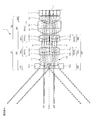
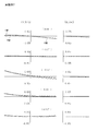
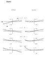
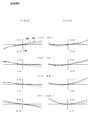
- FIG. 2 is a cross-sectional view along the central axis C of the optical system 1 of Example 1.
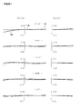
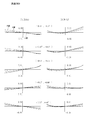
- FIG. 2 is a lateral aberration diagram of the optical system 1 of Example 1.
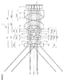
- FIG. 6 is a cross-sectional view along the central axis C of the optical system 1 of Example 2.
- 6 is a lateral aberration diagram of the optical system 1 of Example 2.
- FIG. 6 is a cross-sectional view taken along the central axis C of the optical system 1 of Example 3.
- FIG. 6 is a lateral aberration diagram of the optical system 1 according to Example 3.
- FIG. FIG. 6 is a cross-sectional view along the central axis C of the optical system 1 of Example 4.
- 6 is a lateral aberration diagram of the optical system 1 according to Example 4.
- FIG. FIG. 10 is a cross-sectional view along the central axis C of the optical system 1 of Example 5.
- 6 is a lateral aberration diagram of the optical system 1 according to Example 5.
- FIG. FIG. 12 is a cross-sectional view along the central axis C of the optical system 1 during far-point observation in Example 6.
- FIG. 10 is a cross-sectional view taken along the central axis C of the optical system 1 during near-point observation in Example 6.
- FIG. 10 is a lateral aberration diagram of the optical system 1 during far-point observation according to Example 6.
- FIG. FIG. 25 is a lateral aberration diagram for the deflected first light beam L1 'that passes through the first pupil E1 of the optical system 1 during the near-point observation according to the sixth example.
- 22 is a lateral aberration diagram for the deflected second light beam L2 ′ that passes through the second pupil E2 of the optical system 1 during the near-point observation in Example 6.
- FIG. FIG. 10 is a cross-sectional view along the central axis C of the optical system 1 during far-point observation in Example 7.
- FIG. 10 is a cross-sectional view taken along the central axis C of the optical system 1 during near-point observation in Example 7.
- FIG. 10 is a lateral aberration diagram of the optical system 1 during far-point observation in Example 7.
- FIG. FIG. 25 is a lateral aberration diagram for the deflected first light beam L1 'that passes through the first pupil E1 of the optical system 1 during the near-point observation according to the seventh embodiment.
- FIG. 25 is a lateral aberration diagram for the deflected second light beam L2 'that passes through the second pupil E2 of the optical system 1 during the near-point observation according to the seventh embodiment.
- FIG. 10 is a cross-sectional view including a first front group center axis Cf1 and a second front group center axis Cf2 of the optical system 1 of Example 8. It is the figure seen from the direction orthogonal to FIG.
- FIG. 10 is a lateral aberration diagram of the optical system 1 according to Example 8.
- FIG. 10 is a lateral aberration diagram of the optical system 1 according to Example 8.
- FIG. 10 is a cross-sectional view including a first front group center axis Cf1 and a second front group center axis Cf2 of the optical system 1 of Example 9. It is the figure seen from the direction orthogonal to FIG. 10 is a lateral aberration diagram of the optical system 1 according to Example 8.
- FIG. 10 is a lateral aberration diagram of the optical system 1 according to Example 8.
- FIG. FIG. 22 is a cross-sectional view including a first front group center axis Cf1 and a second front group center axis Cf2 of the optical system 1 of Example 10.
- FIG. 10 is a lateral aberration diagram of the optical system 1 according to Example 8.
- FIG. 10 is a lateral aberration diagram of the optical system 1 according to Example 8.
- FIG. It is a figure which shows the example which used the optical system of this embodiment as an imaging device of a motor vehicle. It is a figure which shows the example which used the optical system of this embodiment as an imaging
- optical system 1 of this embodiment will be described.
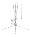
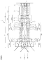
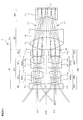
- FIG. 1 is a cross-sectional view taken along a central axis C of an optical system 1 according to an embodiment of the present invention.
- the optical system 1 of the present embodiment is arranged in order from the object side with a first front group center axis Cf2 parallel to the first front group center axis Cf1 and the first front group center axis Cf1 centered on the first front group center axis Cf1.
- the central chief rays of the second light beam L2 that has passed through the second front group Gf2 are preferably convergent lights that do not cross each other until they reach the image plane I after exiting the rear group Gb.
- the first light beam L1 and the second light beam L2 are preferably convergent lights that do not intersect each other until they reach the image plane I after exiting the rear group Gb.
- the stereoscopic imaging system has the following four patterns. 1. An optical system consisting of two completely independent central axes. 2. An optical system comprising a front group of one central axis and a rear group of two central axes from the object side. 3. An optical system comprising a front group of two central axes and a rear group of one central axis from the object side. 4). The whole optical system obtains parallax by pupil division with one central axis.
- This type of optical system is a type that is often employed in small three-dimensional imaging devices, but has a drawback that the total length becomes long.
- FIG. 2 is a view showing the vicinity of the image plane I of the optical system 1 according to an embodiment of the present invention.
- FIG. 47 is a view showing the vicinity of the image plane of the optical system as a reference example. 2 and 47 schematically show the rear group Gb.
- the optical system 1 of this embodiment shown in FIG. 2 and the optical system 100 of the reference example shown in FIG. 47 are composed of a front group and a rear group Gb (not shown) in order from the object side. 2 and 47, the left side is the front side and the right side is the rear side.
- the luminous flux enters the rear group Gb in parallel from the front group of two optical axes (not shown).
- the first central principal ray Lc1 and the second central principal ray Lc2 of the first light flux L1 and the second light flux L2 that are parallel to each other pass through the rear group Gb, and then intersect at a position behind the rear group Gb. This is because the focal position f0 of the incident first light beam L1 and second light beam L2 is a rear position of the rear group Gb. If each of the axial light beams L10 and L20 exiting the front group is parallel light, the images of the first light beam L1 and the second light beam L2 are formed to overlap with the focal position f0 on the rear side of the rear group Gb. Therefore, stereoscopic imaging cannot be performed.
- the optical system 100 of the reference example shown in FIG. 47 is configured to form an image further behind the focal position f0 by diverging each of the axial light beams L10 and L20 emitted from the front group.
- the imaging plane I 1 and the second imaging plane I 2 are arranged side by side. This method is effective when it is desired to make the image size relatively large, and it is possible to form an image as much as possible by increasing the distance from the rear group Gb to the imaging surfaces I 1 and I 2. It becomes. In this case, since the optical paths intersect each other, it is possible to ensure a large imaging surface without increasing the outer diameter of the optical system 100.
- the left and right images are successfully imaged side by side by forming an image before the focal position f0 on the rear side of the rear group Gb.
- the first central chief ray Lc1 and the second central chief ray Lc2 exiting the front group are in the focal position f0 on the rear side of the rear group Gb, as in the reference example shown in FIG. Cross at.
- the optical paths do not intersect before the first imaging plane I 1 and the second imaging plane I 2 .
- the axial light beams L10 and L20 exiting the front group are converged, contrary to the reference example shown in FIG. It is important to.
- the arrangement in which the image is formed at a position closer to the rear group Gb than the focal position f0 on the rear side of the rear group Gb makes it possible to reduce the size of the imaging surfaces I 1 and I 2. Compatibility with is improved. Furthermore, the distance from the rear group Gb to the imaging planes I 1 and I 2 can be significantly shortened as compared with the prior art, and the overall length of the apparatus using the optical system 1 and the optical system 1 is shortened. It becomes possible.
- the distance between the first front group central axis Cf1 and the second front group center axis Cf2 is the same as the first central principal ray Lc1 of the first light beam L1 on the image plane I. It is wider than the interval of the second central principal ray Lc2 of the second light beam L2 on the image plane I.
- the image center interval is preferably narrower than the entrance pupil interval of the optical system.
- the optical axis In the case of stereoscopic viewing at an object point distance of several millimeters to several hundred millimeters, in order to obtain a stereoscopic image that looks natural, it is preferable to give a parallax amount when a human observes with both eyes at normal times. For example, the convergence angle when an observer with a distance of 50 cm and an eye width of 6 cm is stereoscopically viewed is about 7 °. Therefore, in order to obtain the same convergence angle in a stereoscopic imaging optical system that performs magnification observation at a distance of 15 mm, the optical axis The distance needs to be close to about 1.8 mm.
- the Fno of the optical system becomes large, and it is difficult to perform high-resolution imaging.
- the image center interval is narrower than the entrance pupil interval so as to be compatible with a small-sized and high-pixel imaging device.
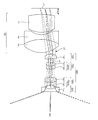
- FIG. 3 is a cross-sectional view taken along the central axis C of the optical system 1 of one embodiment having a rear deflection group according to the present invention.
- a rear deflection group Gbv that is disposed between the rear group Gb and the image plane I and deflects the first light beam L1 and the second light beam L2, and the rear deflection group Gbv emits the rear group Gb.
- the convergence of the subsequent first light beam L1 and the second light beam L2 is relaxed, and the absolute values of the incident angles of the first light beam L1 and the second light beam L2 on the image plane I are smaller than the absolute values of the incident angles on the rear deflection group Gbv. It is preferable to deflect so as to be small.
- the first light beam L1 and the second light beam L2 exit each front group Gf in a convergent manner and form an image on the image plane I in front of each focal position.
- L2 is incident obliquely on the image plane I.
- Recent high-resolution and high-sensitivity imaging devices using a microlens array have incident angle characteristics. Therefore, if the emission characteristics of the optical system 1 do not correspond to the incident angle characteristics of the image plane I, the image periphery There is a possibility that problems such as insufficient light quantity and color blur may occur.
- a rear deflection group that deflects the first light beam L1 and the second light beam L2 tilted in the direction approaching the rear group center axis Cb in a direction away from the rear group center axis Cb is disposed.
- Such a configuration makes it possible to obtain a compact and high-resolution optical system.
- the rear deflection group Gbv may include a first rear deflection group that deflects the first light beam L1 and a second rear deflection group that deflects the second light beam L2.
- the respective deflection groups are respectively in a plane perpendicular to the rear group central axis Cb. It can be rotated and the deflection can be changed with a small amount. Therefore, the image center in the image plane I can be slightly moved, and the center of the first light beam L1 and the center of the second light beam L2 can be finely adjusted.
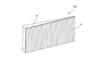
- FIG. 4 is a view showing an example in which the rear deflection member Lbv of the optical system 1 according to the embodiment of the present invention is formed in a wedge prism shape.
- the rear deflection group Gbv includes a rear deflection member Lbv, and the rear deflection member Lbv increases in thickness toward the rear group center axis Cb in the direction toward the outer group with respect to the rear group center axis Cb.
- An element is preferred.
- the rear deflection group Gbv By configuring the rear deflection group Gbv with the rear deflection member Lbv having a refractive action, the rear deflection group Gbv can be formed by polishing or molding, and the productivity can be remarkably improved.
- the rear deflection member Lbv is preferably a wedge prism-shaped optical element.
- both surfaces of the rear deflection member Lbv can be formed as a flat surface, and the productivity can be remarkably improved.
- FIG. 5 is a diagram illustrating an example in which the rear deflection member Lbv of the optical system 1 according to the embodiment of the present invention includes a curved surface.
- the rear deflection group Gbv preferably includes an optical element having a curved surface.
- the post-deflecting member Lbv includes a curved surface, so that the angle of the light beam incident on the image plane can be set more freely.
- the curved surface may be a spherical surface, a toric surface, an anamorphic surface, or a free-form surface.
- FIG. 6 is a diagram illustrating an example of a diffraction grating included in the rear deflection group Gbv of the optical system 1 according to an embodiment of the present invention.
- the rear deflection group Gbv may include a diffractive optical element da.
- the diffractive optical element da may have an arbitrary shape.
- the rear deflection group Gbv includes the diffractive optical element da, the occurrence of tilt of the image surface and coma aberration is reduced, the burden of aberration correction in the rear group Gb is reduced, and the optical system is further improved. It becomes possible to reduce the size.
- FIG. 7 is a diagram showing an example in which a diffraction grating is attached to a wedge prism included in the rear deflection group Gbv of the optical system 1 according to an embodiment of the present invention.
- the wedge-shaped prismatic optical element Lbv and the diffractive optical element da may be joined and used. Further, as shown in FIG. 6, the diffractive optical element da may have an arbitrary shape.
- the first front group Gf1 and the second front group Gf2 include a plano-concave negative lens Lf1 11 and Lf2 11 in order from the object side. It is preferable to include the groups Gf1 1 and Gf2 1 and the second groups Gf1 2 and Gf2 2 including the positive cemented lenses SUf1 21 and SUf2 21 .
- the front first group Gf1 1 and Gf2 1 having a strong negative refractive power for taking in a light beam with a wide angle of view and reducing the angle of the off-axis principal ray, and the front first group
- the first lens group G2 includes a front two groups Gf1 2 and Gf2 2 including a positive cemented lens that strongly corrects the lateral chromatic aberration generated in Gf1 1 and Gf2 1 .
- the front one group Gf1 1, Gf2 1 consisting of a plano Lf1 11, Lf2 11, a second group Gf1 2, Gf2 2 before a cemented meniscus lens suf1 21, suf2 21 having a concave surface on the object side, It is preferable to make it the structure containing these.
- the first front group Gf1 and the second front group Gf2 are respectively the front second group Gf1 2 and Gf2 2 on the rear group Gb side of the front second group Gf1 2 and Gf2 2. It is preferable to have front three groups Gf1 3 and Gf2 3 including different positive cemented lenses SUf1 31 and SUf2 31 .
- the luminous flux whose angle of view has been reduced by the front group Gf1 1 and Gf2 1 and the front group Gf1 2 and Gf2 2 of the front group Gf becomes a convergent beam in the front group Gf1 3 and Gf2 3 of the front group Gf. .
- a high load is applied to the front group Gf. Therefore, it is preferable to have the front three groups Gf1 3 and Gf2 3 that correct axial chromatic aberration with at least a cemented lens. Further, it is preferable to have front four groups Gf1 4 and Gf2 4 made of a single positive lens.
- FIG. 8 is a diagram illustrating the position of an image formed only by the front group Gf of the optical system 1 according to an embodiment of the present invention.
- FIG. 9 is a diagram illustrating the focal length f of the optical system 1 according to an embodiment of the present invention.
- the optical system 1 of the present embodiment preferably satisfies the following conditional expression (1).
- FAb is the distance from the final surface of the front group Gf to the imaging position where the light beam exiting the front group Gf forms an image
- f is the focal length of the entire optical system, It is.
- the distance from the final surface of the front group Gf to the imaging position If where the light beam exiting the front group Gf forms an image is FAb.
- the focal length of the entire optical system 1 is assumed to be f.
- the optical system 1 is an eccentric optical system, the eccentricity is removed, a parallel light beam is incident on the optical system 1 from infinity, and the on-axis marginal ray L1 ′ incident on the optical system 1 is emitted after passing through the optical system 1.
- the distance from the virtually bent position A to the image plane I is defined as the focal length f of the optical system 1.
- the optical system 1 of the present embodiment satisfies the following conditional expression (1 ′).
- FIG. 10 is a diagram for explaining the position of the image in a state in which the filter F of the optical system 1 according to the embodiment of the present invention is removed.
- the optical system 1 of the present embodiment preferably satisfies the following conditional expression (2).
- Lb / f ⁇ 5 (2)
- Lb is the distance from the final surface of the rear group Gb to the image plane I
- f is the focal length of the entire optical system 1; It is.
- the optical system 1 of the present embodiment satisfies the following conditional expression (2 ′). Lb / f ⁇ 3 (2 ′)
- optical system 1 of the present embodiment satisfies the following conditional expression (2 ′′). Lb / f ⁇ 2 (2 ′′)
- FIG. 11 is a cross-sectional view taken along the central axis C of the optical system 1 according to another embodiment of the present invention.
- FIG. 12 is a diagram showing the pupil division member 3.
- An optical system 1 includes a shielding member 2 that is disposed in the first front group Gf1 and shields the first light beam L1, and is disposed in the second front group Gf2 and deflects the second light beam L2. It is preferable to include the pupil division member 3.
- the object point distance during stereoscopic observation is 30 cm from infinity, and 0 to 3 m -1 in diopter.
- the object distance is 20 mm to 1 mm, and if it is also diopter, it is 50 to 1000 m ⁇ 1 . For this reason, it is impossible to cope with stereoscopic observation unless the baseline length is changed.
- the optical system 1 of the present embodiment relates to a mechanism for changing the base line length of the three-dimensional magnification optical system in which the object point distance changes greatly as described above.
- stereoscopic imaging is performed with a general optical system 1 having two optical paths.
- a pupil that is a pupil division element that shields the first light beam L1 passing through the first optical path of the two optical paths by the shielding member 2 and divides the pupil into another second optical path.
- the dividing member 3 is inserted and the second light beam L2 is divided into a deflected first light beam L1 ′ and a deflected second light beam L2 ′ by pupil division, and stereoscopic imaging is performed. Therefore, it is possible to obtain a natural three-dimensional effect by switching the base line length corresponding to a significantly different object point distance.
- the pupil dividing member 3 includes a first pupil E1 that forms an image without deflecting a part of the second light beam L2, and a second light beam L2. Of these, it is preferable to form a second pupil E2 that forms an image at a different position on the same plane as the position where the other pupil is imaged by the first pupil E1.
- Pupil dividing member 3 to divide the pupil has a parallel plate portion 3 1 which corresponds to the first pupil E1, a wedge prism portion 3 2 which corresponds to the second pupil E2, the.
- the pupil splitting member 3 has the wedge-shaped prism portion 3 2 having a deflection action, and the second pupil E2 is placed at an adjacent position in the same plane from the imaging position of the deflected first light beam L1 ′ passing through the first pupil E1. It has the action of moving the imaging position of the deflected second light beam L2 ′ that passes therethrough.
- the pupil division member 3 has a positive refractive power, and an imaging position at the time of far-point observation when the pupil division member 3 is not used, It is preferable that the imaging position at the time of near-point observation when the pupil dividing member 3 is used is the same or substantially the same.
- the shielding member 2 and the pupil division member 3 are disposed between the corresponding lenses of the first front group Gf1 and the second front group Gf2. It is preferable.
- the first front 1 group Gf1 1 of plano-concave negative lens Lf1 11 are first cut-out portion 41 1 lacking second front lens group Gf2 side partially cut is formed
- the second The plano-concave negative lens Lf2 11 of the front first group Gf2 1 may be formed with a second notch 41 2 that is partially cut away from the first front group Gf1 side.
- the 1st notch part 41 1 and the 2nd notch part 41 2 are contact
- the distance between the first optical axis of the first front group Gf1 and the second optical axis of the second front group Gf2 is reduced by contacting the first notch part 41 1 and the second notch part 41 2.
- the optical system 1 can be reduced in size.
- the notch is not limited to the first front first group Gf1 1 and the second front first group Gf2 1 , for example, the first front second group Gf1 2, the second front second group Gf2 2 , the first front third group Gf1 3 and the second front third group Gf2 3 may be formed on the lenses of the other first front group Gf1 and the second front group Gf2, and may be brought into contact with each other.
- the light shielding member 5 may be installed between the first cutout portion 41 1 and the second cutout portion 41 2 . By installing the light shielding member 5, it is possible to reduce the possibility that each flare light will be incident between the first front group Gf1 and the second front group Gf2 even if the baseline length is shortened.
- the color misregistration of the image that occurs when deflected by the pupil division member 3 can be corrected electronically. More preferably, shading that occurs when the angle of light incident on the image sensor increases can be corrected electronically.
- Examples 1 to 10 of the optical system 1 according to the present embodiment will be described below.
- the numerical data of Examples 1 to 10 will be described later.
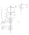
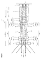
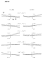
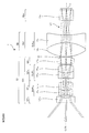
- FIG. 13 is a sectional view taken along the central axis C of the optical system 1 of the first embodiment.
- 14 is a lateral aberration diagram of the optical system 1 of Example 1.
- the angle shown in the center indicates (vertical angle of view), and indicates lateral aberration in the Y direction (meridional direction) and X direction (sagittal direction) at that angle of view.
- a negative angle of view means a clockwise angle facing the positive direction of the X axis. The same applies to the lateral aberration diagrams of Examples 1 to 10.
- the optical system 1 of Embodiment 1 is arranged in parallel with the first front group central axis Cf1 having the first front group central axis Cf1 and the first front group central axis Cf1 in order from the object side to the image side.
- the first front group Gf1 includes a first front first group Gf1 1 having a plano-concave negative lens Lf1 11 facing the object side, a cemented lens SUf1 21 of a biconcave negative lens Lf1 21 and a biconvex positive lens Lf1 22.
- a first front second group Gf1 2 having, a negative meniscus lens Lf1 31 having a convex surface on the object side of the first front third group Gf1 3 having a cemented lens suf1 31 of the biconvex positive lens Lf1 32, the first diaphragm S1
- a first front fourth group Gf1 4 having a positive meniscus lens Lf1 41 having a convex surface facing the image surface side.
- the second front group Gf2 includes a second front first group Gf2 1 having a plano-concave negative lens Lf2 11 facing the object side, a cemented lens SUf2 21 of a biconcave negative lens Lf2 21 and a biconvex positive lens Lf2 22.
- a second front second group Gf2 2 having, a negative meniscus lens Lf2 31 having a convex surface directed toward the object side and a second front third group Gf2 3 having a cemented lens suf2 31 of the biconvex positive lens Lf2 32, a second diaphragm S2
- a second front fourth group Gf2 4 having a positive meniscus lens Lf2 41 with a convex surface facing the image surface side.
- Rear group Gb includes a first group Gb1 after having cemented lens SUB1 1 of the biconvex positive lens Lb 1 a biconcave negative lens Lb 2, the two groups Gb2 after having biconvex positive lens Lb 3, a.
- a filter is placed in front of the image plane I.
- the first light beam L1 incident from the first object surface, not shown in the first front group Gf1 is first pre-1 group Gf1 1 of plano-concave negative lens Lf1 11, first front second group Gf1 2 of cemented lens suf1 21, the The first front group Gf1 3 passes through the cemented lens SUf1 31 , the first aperture stop S1, and the first front fourth group Gf1 4 positive meniscus lens Lf1 41 , and then exits the first front group Gf1. Incident on Gb.
- the second light beam L2 incident on the second front group Gf2 from the second object plane is a plano-concave negative lens Lf2 11 of the second front first group Gf2 1 , a cemented lens SUf2 21 of the second front second group Gf2 2 , 2 After passing through the cemented lens SUf2 31 of the front 3rd group Gf2 3 , the second aperture stop S2, and the positive meniscus lens Lf2 41 of the 2nd front 4th group Gf2 4 , the second front group Gf2 is emitted, and then the rear group Incident on Gb.
- the first light beam L1 and the second light beam L2 incident on the rear group Gb pass through the cemented lens SUb1 1 of the rear first group Gb1, the biconvex positive lens Lb 3 of the rear second group Gb2, and the filter F, respectively. Is incident on.
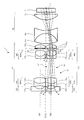
- FIG. 15 is a cross-sectional view taken along the central axis C of the optical system 1 of the second embodiment.
- FIG. 16 is a lateral aberration diagram of the optical system 1 of Example 2.
- the optical system 1 of Example 2 is arranged in parallel with the first front group center axis Cf1 having the first front group center axis Cf1 and the first front group center axis Cf1 in order from the object side to the image side.
- the first front group Gf1 includes a first front first group Gf1 1 having a plano-concave negative lens Lf1 11 facing the object side, a cemented lens SUf1 21 of a biconcave negative lens Lf1 21 and a biconvex positive lens Lf1 22.
- a first front second group Gf1 2 having, a negative meniscus lens Lf1 31 having a convex surface on the object side of the first front third group Gf1 3 having a cemented lens suf1 31 of the biconvex positive lens Lf1 32, the first diaphragm S1
- a first front fourth group Gf1 4 having a positive meniscus lens Lf1 41 having a convex surface facing the image surface side.
- the second front group Gf2 includes a second front first group Gf2 1 having a plano-concave negative lens Lf2 11 facing the object side, a cemented lens SUf2 21 of a biconcave negative lens Lf2 21 and a biconvex positive lens Lf2 22.
- a second front second group Gf2 2 having, a negative meniscus lens Lf2 31 having a convex surface directed toward the object side and a second front third group Gf2 3 having a cemented lens suf2 31 of the biconvex positive lens Lf2 32, a second diaphragm S2
- a second front fourth group Gf2 4 having a positive meniscus lens Lf2 41 with a convex surface facing the image surface side.
- Rear group Gb includes a first group Gb1 after having cemented lens SUB1 1 of the biconvex positive lens Lb 1 a biconcave negative lens Lb 2, the two groups Gb2 after having biconvex positive lens Lb 3, a.
- a filter is placed in front of the image plane I.
- the plano-concave negative lens Lf1 11 of the first front first group Gf1 1 is formed with a first front first group first cutout portion 4 11 that is partially cut away from the second front group Gf2 side, and the second front first group Gf2 1 of plano-concave negative lens Lf2 11, the second front group 1 second notch 4 12 lacking the first front group Gf1 side partially cut is formed.
- the first light beam L1 incident from the first object surface, not shown in the first front group Gf1 is first pre-1 group Gf1 1 of plano-concave negative lens Lf1 11, first front second group Gf1 2 of cemented lens suf1 21, the The first front group Gf1 3 passes through the cemented lens SUf1 31 , the first aperture stop S1, and the first front fourth group Gf1 4 positive meniscus lens Lf1 41 , and then exits the first front group Gf1. Incident on Gb.
- the second light beam L2 incident on the second front group Gf2 from the second object plane is a plano-concave negative lens Lf2 11 of the second front first group Gf2 1 , a cemented lens SUf2 21 of the second front second group Gf2 2 , 2 After passing through the cemented lens SUf2 31 of the front 3rd group Gf2 3 , the second aperture stop S2, and the positive meniscus lens Lf2 41 of the 2nd front 4th group Gf2 4 , the second front group Gf2 is emitted, and then the rear group Incident on Gb.
- the first light beam L1 and the second light beam L2 incident on the rear group Gb pass through the cemented lens SUb1 1 of the rear first group Gb1, the biconvex positive lens Lb 3 of the rear second group Gb2, and the filter F, respectively. Is incident on.
- FIG. 17 is a cross-sectional view taken along the central axis C of the optical system 1 of the third embodiment.
- FIG. 18 is a lateral aberration diagram of the optical system 1 of Example 3.
- the optical system 1 of Example 3 is arranged in parallel with the first front group Gf1 having the first front group center axis Cf1 and the first front group center axis Cf1 in order from the object side to the image side.
- the first front group Gf1 includes a first front first group Gf1 1 having a plano-concave negative lens Lf1 11 facing the object side, a cemented lens SUf1 21 of a biconcave negative lens Lf1 21 and a biconvex positive lens Lf1 22.
- a first front second group Gf1 2 having, a first aperture S1, a negative meniscus lens Lf1 31 having a convex surface on the object side of the first front third group Gf1 3 having a cemented lens suf1 31 of the biconvex positive lens Lf1 32 are preferably provided.
- the second front group Gf2 includes a second front first group Gf2 1 having a plano-concave negative lens Lf2 11 facing the object side, a cemented lens SUf2 21 of a biconcave negative lens Lf2 21 and a biconvex positive lens Lf2 22.
- a second front second group Gf2 2 having, a second diaphragm S2, a negative meniscus lens Lf2 31 having a convex surface directed toward the object side and a second front third group Gf2 3 having a cemented lens suf2 31 of the biconvex positive lens Lf2 32 are preferably provided.
- Rear group Gb includes a first group Gb1 after having cemented lens SUB1 1 of the biconvex positive lens Lb 1 a biconcave negative lens Lb 2, the two groups Gb2 after having biconvex positive lens Lb 3, a.
- a filter is placed in front of the image plane I.
- the plano-concave negative lens Lf1 11 of the first front first group Gf1 1 is formed with a first front first group first cutout portion 4 11 that is partially cut away from the second front group Gf2 side, and the second front first group Gf2 1 of plano-concave negative lens Lf2 11, the second front group 1 second notch 4 12 lacking the first front group Gf1 side partially cut is formed.
- a light shielding member may be provided between the notch portions where the first front group Gf1 and the second front group Gf2 are in contact.
- the first light beam L1 incident from the first object surface, not shown in the first front group Gf1 is first pre-1 group Gf1 1 of plano-concave negative lens Lf1 11, first front second group Gf1 2 of cemented lens suf1 21, the 1 diaphragm S1 and passes through the cemented lens suf1 31 in the first front third group Gf1 3, a first front unit Gf1 injection, then enters the rear group Gb.
- the second light beam L2 incident on the second front group Gf2 from the second object plane is a plano-concave negative lens Lf2 11 of the second front first group Gf2 1 , a cemented lens SUf2 21 of the second front second group Gf2 2 , After passing through the second stop S2 and the cemented lens SUf2 31 of the second front third group Gf2 3 , the second front group Gf2 exits and then enters the rear group Gb.
- the first light beam L1 and the second light beam L2 incident on the rear group Gb pass through the cemented lens SUb1 1 of the rear first group Gb1, the biconvex positive lens Lb 3 of the rear second group Gb2, and the filter F, respectively. Is incident on.
- FIG. 19 is a cross-sectional view taken along the central axis C of the optical system 1 of the fourth embodiment.
- FIG. 20 is a lateral aberration diagram of the optical system 1 according to Example 4.
- the optical system 1 of Example 4 is arranged in parallel with the first front group Gf1 having the first front group center axis Cf1 and the first front group center axis Cf1 in order from the object side to the image side.
- the first front group Gf1 includes a first front first group Gf1 1 having a plano-concave negative lens Lf1 11 facing the object side, a cemented lens SUf1 21 of a biconcave negative lens Lf1 21 and a biconvex positive lens Lf1 22.
- a first front second group Gf1 2 having, a first aperture S1, a negative meniscus lens Lf1 31 having a convex surface on the object side of the first front third group Gf1 3 having a cemented lens suf1 31 of the biconvex positive lens Lf1 32 are preferably provided.
- the second front group Gf2 includes a second front first group Gf2 1 having a plano-concave negative lens Lf2 11 facing the object side, a cemented lens SUf2 21 of a biconcave negative lens Lf2 21 and a biconvex positive lens Lf2 22.
- a second front second group Gf2 2 having, a second diaphragm S2, a negative meniscus lens Lf2 31 having a convex surface directed toward the object side and a second front third group Gf2 3 having a cemented lens suf2 31 of the biconvex positive lens Lf2 32 are preferably provided.
- Rear group Gb includes a first group Gb1 after having cemented lens SUB1 1 of the biconvex positive lens Lb 1 a biconcave negative lens Lb 2, the two groups Gb2 after having biconvex positive lens Lb 3, a.
- a filter is placed in front of the image plane I.
- the plano-concave negative lens Lf1 11 of the first front first group Gf1 1 is formed with a first front first group first cutout portion 4 11 that is partially cut away from the second front group Gf2 side, and the second front first group Gf2 1 of plano-concave negative lens Lf2 11, the second front group 1 second notch 4 12 lacking the first front group Gf1 side partially cut is formed.
- the negative meniscus lens Lf1 31 having a convex surface facing the object side of the first front third group Gf1 3 and the cemented lens SUf1 31 of the biconvex positive lens Lf1 32 are partially cut away on the second front group Gf2 side.
- a cemented lens SUf2 31 of a negative meniscus lens Lf2 31 and a biconvex positive lens Lf2 32 having a front third group first cutout portion 4 31 and having a convex surface facing the object side of the second front third group Gf2 3 second front third group second cut-out portion 4 32 are formed devoid of front group Gf1 side partially cut.
- the first light beam L1 incident from the first object surface, not shown in the first front group Gf1 is first pre-1 group Gf1 1 of plano-concave negative lens Lf1 11, first front second group Gf1 2 of cemented lens suf1 21, the 1 diaphragm S1 and passes through the cemented lens suf1 31 in the first front third group Gf1 3, a first front unit Gf1 injection, then enters the rear group Gb.
- the second light beam L2 incident on the second front group Gf2 from the second object plane is a plano-concave negative lens Lf2 11 of the second front first group Gf2 1 , a cemented lens SUf2 21 of the second front second group Gf2 2 , After passing through the second stop S2 and the cemented lens SUf2 31 of the second front third group Gf2 3 , the second front group Gf2 exits and then enters the rear group Gb.
- the first light beam L1 and the second light beam L2 incident on the rear group Gb pass through the cemented lens SUb1 1 of the rear first group Gb1, the biconvex positive lens Lb 3 of the rear second group Gb2, and the filter F, respectively. Is incident on.
- FIG. 21 is a cross-sectional view taken along the central axis C of the optical system 1 of the fifth embodiment.
- FIG. 22 is a lateral aberration diagram of the optical system 1 according to Example 5.
- the optical system 1 of Example 5 is arranged in parallel with the first front group center axis Cf1 and the first front group center axis Cf1 having the first front group center axis Cf1 in order from the object side to the image side.
- the first front group Gf1 includes a first front first group Gf1 1 having a plano-concave negative lens Lf1 11 facing the object side, a cemented lens SUf1 21 of a biconcave negative lens Lf1 21 and a biconvex positive lens Lf1 22.
- a first front second group Gf1 2 having, a first aperture S1, a negative meniscus lens Lf1 31 having a convex surface on the object side of the first front third group Gf1 3 having a cemented lens suf1 31 of the biconvex positive lens Lf1 32 are preferably provided.
- the second front group Gf2 includes a second front first group Gf2 1 having a plano-concave negative lens Lf2 11 facing the object side, a cemented lens SUf2 21 of a biconcave negative lens Lf2 21 and a biconvex positive lens Lf2 22.
- a second front second group Gf2 2 having, a second diaphragm S2, a negative meniscus lens Lf2 31 having a convex surface directed toward the object side and a second front third group Gf2 3 having a cemented lens suf2 31 of the biconvex positive lens Lf2 32 are preferably provided.
- the rear group Gb includes a rear first group Gb1 having a positive meniscus lens Lb 1 with a convex surface facing the image surface side, and a rear second group Gb2 having a cemented lens SUb2 1 of a biconvex positive lens Lb 2 and a biconcave negative lens Lb 3. And comprising.
- a filter is placed in front of the image plane I.
- the plano-concave negative lens Lf1 11 of the first front first group Gf1 1 is formed with a first front first group first cutout portion 4 11 that is partially cut away from the second front group Gf2 side, and the second front first group Gf2 1 of plano-concave negative lens Lf2 11, the second front group 1 second notch 4 12 lacking the first front group Gf1 side partially cut is formed.
- a light shielding member may be installed between the notch portions where the first front group Gf1 and the third front group Gf3 abut.
- the first light beam L1 incident from the first object surface, not shown in the first front group Gf1 is first pre-1 group Gf1 1 of plano-concave negative lens Lf1 11, first front second group Gf1 2 of cemented lens suf1 21, the 1 diaphragm S1 and passes through the cemented lens suf1 31 in the first front third group Gf1 3, a first front unit Gf1 injection, then enters the rear group Gb.
- the second light beam L2 incident on the second front group Gf2 from the second object plane is a plano-concave negative lens Lf2 11 of the second front first group Gf2 1 , a cemented lens SUf2 21 of the second front second group Gf2 2 , After passing through the second stop S2 and the cemented lens SUf2 31 of the second front third group Gf2 3 , the second front group Gf2 exits and then enters the rear group Gb.
- the first light beam L1 and the second light beam L2 incident on the rear group Gb pass through the positive meniscus lens Lb 1 of the rear first group Gb1, the cemented lens SUb2 1 of the rear second group Gb2, and the filter F, respectively. Incident.
- FIG. 23 is a cross-sectional view taken along the central axis C of the optical system 1 during far-point observation in Example 6.
- FIG. 24 is a cross-sectional view along the central axis C of the optical system 1 during near-point observation in Example 6.
- FIG. 25 is a lateral aberration diagram of the optical system 1 during the far-point observation in Example 6.
- FIG. 26 is a lateral aberration diagram for the deflected first light beam L1 'that passes through the first pupil E1 of the optical system 1 during the near-point observation according to the sixth embodiment.
- FIG. 27 is a lateral aberration diagram for the deflected second light beam L2 'that passes through the second pupil E2 of the optical system 1 during the near-point observation in Example 6.
- the optical system 1 of Example 6 is arranged in parallel with the first front group Gf1 having the first front group center axis Cf1 and the first front group center axis Cf1 in order from the object side to the image side.
- the first front group Gf1 includes a first front first group Gf1 1 having a plano-concave negative lens Lf1 11 facing the object side, a cemented lens SUf1 21 of a biconcave negative lens Lf1 21 and a biconvex positive lens Lf1 22.
- a first front second group Gf1 2 having, a negative meniscus lens Lf1 31 having a convex surface on the object side of the first front third group Gf1 3 having a cemented lens suf1 31 of the biconvex positive lens Lf1 32, the first diaphragm S1
- a first front fourth group Gf1 4 having a negative meniscus lens Lf1 41 having a convex surface directed toward the image surface side.
- the second front group Gf2 includes a second front first group Gf2 1 having a plano-concave negative lens Lf2 11 facing the object side, a cemented lens SUf2 21 of a biconcave negative lens Lf2 21 and a biconvex positive lens Lf2 22.
- a second front second group Gf2 2 having, a negative meniscus lens Lf2 31 having a convex surface directed toward the object side and a second front third group Gf2 3 having a cemented lens suf2 31 of the biconvex positive lens Lf2 32, a second diaphragm S2
- a second front fourth group Gf2 4 having a negative meniscus lens Lf2 41 having a convex surface directed toward the image surface side.
- Rear group Gb includes a biconvex positive lens Lb 1 and 1 group Gb1 after having cemented lens SUB1 1 of the biconcave negative lens Lb 2, the two groups Gb2 after having a positive meniscus lens Lb 3 having a convex surface facing the object side .
- a filter is placed in front of the image plane I.
- the first light beam L1 incident from the first object surface, not shown in the first front group Gf1 is first pre-1 group Gf1 1 of plano-concave negative lens Lf1 11, first front second group Gf1 2 of cemented lens suf1 21, the The first front group Gf1 3 passes through the cemented lens SUf1 31 , the first aperture stop S1, and the first front fourth group Gf1 4 negative meniscus lens Lf1 41 , and then the first front group Gf1 is emitted, and then the rear group Incident on Gb.
- the second light beam L2 incident on the second front group Gf2 from the second object plane is a plano-concave negative lens Lf2 11 of the second front first group Gf2 1 , a cemented lens SUf2 21 of the second front second group Gf2 2 , 2 After passing through the cemented lens SUf2 31 of the front third group Gf2 3 , the second diaphragm S2, and the negative meniscus lens Lf2 41 of the second front fourth group Gf2 4 , the second front group Gf2 is emitted, and then the rear group Incident on Gb.
- the first light beam L1 and the second light beam L2 incident on the rear group Gb pass through the cemented lens SUb1 1 of the rear first group Gb1, the positive meniscus lens Lb 3 of the rear second group Gb2, and the filter F, respectively. Incident.
- the optical system 1 of Example 6 can perform near-point observation by installing a shielding member 2 and a pupil dividing member 3.
- the shielding member 2 shields the first light beam L1 shown in FIG. In the example shown in FIG. 24, the shielding member 2 is installed between the rear first group Gb1 and the rear second group Gb2 of the rear group Gb, but the shielding member 2 is installed between any of the lenses of the first front group Gf1. May be.
- the shielding member 2 may be installed between the front group Gf and the rear group Gb.
- the pupil dividing member 3 forms an image with the first pupil E1 that forms an image without deflecting a part of the second light beam L2 shown in FIG. 23, and the other portion of the second light beam L2 with the first pupil. And a second pupil E2 that forms an image at a different position on the same plane as the position to be formed.
- Pupil dividing member 3 to divide the pupil has a parallel plate portion 3 1 which corresponds to the first pupil E1, a wedge prism portion 3 2 which corresponds to the second pupil E2, the.
- the pupil splitting member 3 has the wedge-shaped prism portion 3 2 having a deflection action, and the second pupil E2 is placed at an adjacent position in the same plane from the imaging position of the deflected first light beam L1 ′ passing through the first pupil E1. It has the action of moving the imaging position of the deflected second light beam L2 ′ that passes therethrough.
- FIG. 28 is a cross-sectional view along the central axis C of the optical system 1 during far-point observation in Example 7.
- FIG. 29 is a cross-sectional view along the central axis C of the optical system 1 during near-point observation in Example 7.
- FIG. 30 is a lateral aberration diagram of the optical system 1 during the far-point observation in Example 7.
- FIG. 31 is a lateral aberration diagram for the deflected first light beam L1 'that passes through the first pupil E1 of the optical system 1 during the near-point observation in Example 7.
- FIG. 32 is a transverse aberration diagram for the deflected second light beam L2 'that passes through the second pupil E2 of the optical system 1 during the near-point observation according to the seventh embodiment.
- the optical system 1 of Example 7 is arranged in parallel with the first front group Gf1 having the first front group center axis Cf1 and the first front group center axis Cf1 in order from the object side to the image side.
- the first front group Gf1 includes a first front first group Gf1 1 having a plano-concave negative lens Lf1 11 facing the object side, a cemented lens SUf1 21 of a biconcave negative lens Lf1 21 and a biconvex positive lens Lf1 22.
- a first front second group Gf1 2 having, a negative meniscus lens Lf1 31 having a convex surface on the object side of the first front third group Gf1 3 having a cemented lens suf1 31 of the biconvex positive lens Lf1 32, the first diaphragm S1
- a first front fourth group Gf1 4 having a negative meniscus lens Lf1 41 having a convex surface directed toward the image surface side.
- the second front group Gf2 includes a second front first group Gf2 1 having a plano-concave negative lens Lf2 11 facing the object side, a cemented lens SUf2 21 of a biconcave negative lens Lf2 21 and a biconvex positive lens Lf2 22.
- a second front second group Gf2 2 having, a negative meniscus lens Lf2 31 having a convex surface directed toward the object side and a second front third group Gf2 3 having a cemented lens suf2 31 of the biconvex positive lens Lf2 32, a second diaphragm S2
- a second front fourth group Gf2 4 having a negative meniscus lens Lf2 41 having a convex surface directed toward the image surface side.
- Rear group Gb includes a first group Gb1 after having cemented lens SUB1 1 of the biconvex positive lens Lb 1 a biconcave negative lens Lb 2, the two groups Gb2 after having biconvex positive lens Lb 3, a.
- a filter is placed in front of the image plane I.
- the first light beam L1 incident from the first object surface, not shown in the first front group Gf1 is first pre-1 group Gf1 1 of plano-concave negative lens Lf1 11, first front second group Gf1 2 of cemented lens suf1 21, the The first front group Gf1 3 passes through the cemented lens SUf1 31 , the first aperture stop S1, and the first front fourth group Gf1 4 negative meniscus lens Lf1 41 , and then the first front group Gf1 is emitted, and then the rear group Incident on Gb.
- the second light beam L2 incident on the second front group Gf2 from the second object plane is a plano-concave negative lens Lf2 11 of the second front first group Gf2 1 , a cemented lens SUf2 21 of the second front second group Gf2 2 , 2 After passing through the cemented lens SUf2 31 of the front third group Gf2 3 , the second diaphragm S2, and the negative meniscus lens Lf2 41 of the second front fourth group Gf2 4 , the second front group Gf2 is emitted, and then the rear group Incident on Gb.
- the first light beam L1 and the second light beam L2 incident on the rear group Gb pass through the cemented lens SUb1 1 of the rear first group Gb1, the biconvex positive lens Lb 3 of the rear second group Gb2, and the filter F, respectively. Is incident on.
- the optical system 1 of Example 7 can perform near-point observation by installing a shielding member 2 and a pupil dividing member 3.
- the shielding member 2 shields the first light beam L1 shown in FIG. In the example shown in FIG. 29, the shielding member 2 is installed in the vicinity of the first diaphragm S1 between the first front third group Gf1 3 and the first front fourth group Gf1 4 .
- the pupil splitting member 3 forms an image with the first pupil E1 that forms an image without deflecting a part of the second light beam L2 shown in FIG. 28 and the other portion of the second light beam L2 with the first pupil. And a second pupil E2 that forms an image at a different position on the same plane as the position to be formed.
- Pupil dividing member 3 to divide the pupil has a parallel plate portion 3 1 which corresponds to the first pupil E1, a wedge prism portion 3 2 which corresponds to the second pupil E2, the.
- the pupil splitting member 3 has the wedge-shaped prism portion 3 2 having a deflection action, and the second pupil E2 is placed at an adjacent position in the same plane from the imaging position of the deflected first light beam L1 ′ passing through the first pupil E1. It has the action of moving the imaging position of the deflected second light beam L2 ′ that passes therethrough.
- the light shielding member 2 is disposed in the vicinity of the first diaphragm S1 between the first front third group Gf1 3 and the first front fourth group Gf1 4 , and the pupil division member 3 is disposed on the second front side. It is arranged in the vicinity of the second diaphragm S2 between the third group Gf2 3 and the second front fourth group Gf2 4 . That is, the light shielding member 2 and the pupil division member 3 are disposed between the corresponding lenses of the first front group Gf1 and the second front group Gf2.
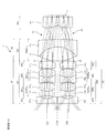
- FIG. 33 is a cross-sectional view including the first front group center axis Cf1 and the second front group center axis Cf2 of the optical system 1 according to the eighth embodiment.
- FIG. 34 is a diagram viewed from a direction orthogonal to FIG. 35 and 36 are lateral aberration diagrams of the optical system 1 of Example 8.
- FIG. 34 is a diagram viewed from a direction orthogonal to FIG. 35 and 36 are lateral aberration diagrams of the optical system 1 of Example 8.
- the optical system 1 of Example 8 is arranged in parallel with the first front group center axis Cf1 having the first front group center axis Cf1 and the first front group center axis Cf1 in order from the object side to the image side.
- a rear deflection group Gbv arranged.
- the first front group Gf1 includes a first front first group Gf1 1 having a plano-concave negative lens Lf1 11 facing the object side, a cemented lens SUf1 21 of a biconcave negative lens Lf1 21 and a biconvex positive lens Lf1 22.
- a first front second group Gf1 2 having, a negative meniscus lens Lf1 31 having a convex surface on the object side of the first front third group Gf1 3 having a cemented lens suf1 31 of the biconvex positive lens Lf1 32, the first diaphragm S1 are preferably provided.
- the image side surface of the plano-concave negative lens Lf1 11 is an aspherical surface.
- the second front group Gf2 includes a second front first group Gf2 1 having a plano-concave negative lens Lf2 11 facing the object side, a cemented lens SUf2 21 of a biconcave negative lens Lf2 21 and a biconvex positive lens Lf2 22.
- a second front second group Gf2 2 having, a negative meniscus lens Lf2 31 having a convex surface directed toward the object side and a second front third group Gf2 3 having a cemented lens suf2 31 of the biconvex positive lens Lf2 32, a second diaphragm S2 are preferably provided.
- the image side surface of the plano-concave negative lens Lf2 11 is aspheric.
- the rear group Gb preferably includes a rear first group Gb1 having a biconvex positive lens Lb 1 and a biconcave negative lens Lb 2 .
- the rear deflection group Gbv is disposed between the rear group Gb and the image plane I and includes a rear deflection member Lbv that deflects the first light beam L1 and the second light beam L2.
- the rear deflection member Lbv relaxes the convergence of the first light beam L1 and the second light beam L2 after exiting the rear group Gb, and the absolute values of the incident angles of the first light beam L1 and the second light beam L2 on the image plane I are reduced.
- Deflection is preferably performed so as to be smaller than the absolute value of the incident angle to the rear deflection group Gbv.
- the first light beam L1 incident on the first front group Gf1 from the first object surface is a plano-concave negative lens Lf1 11 of the first front first group Gf1 1 , a cemented lens SUf1 21 of the first front second group Gf1 2 , the first front
- the light passes through the cemented lens SUf1 31 of the third group Gf1 3 and the first diaphragm S1, exits the first front group Gf1, and then enters the rear group Gb.
- the second light beam L2 incident on the second front group Gf2 from the second object plane includes a plano-concave negative lens Lf2 11 of the second front first group Gf2 1 , a cemented lens SUf2 21 of the second front second group Gf2 2, a second front
- the light passes through the cemented lens SUf2 31 of the third group Gf2 3 and the second diaphragm S2, exits the second front group Gf2, and then enters the rear group Gb.
- the first light beam L1 and the second light beam L2 incident on the rear group Gb pass through the biconvex positive lens Lb 1 , the biconcave negative lens Lb 2 of the rear first group Gb1, and the rear deflection member Lbv of the rear deflection group Gbv, respectively. Is incident on the image plane.
- the rear deflection group Gbv includes a rear deflection member Lbv, and the rear deflection member Lbv moves rearward toward the outer peripheral side with respect to the rear group central axis Cb.
- This is an optical element having a large thickness in the group center axis Cb direction.
- the rear deflection group Gbv By configuring the rear deflection group Gbv with the rear deflection member Lbv having a refractive action, the rear deflection group Gbv can be formed by polishing or molding, and the productivity can be remarkably improved.
- the rear deflection member Lbv is an optical element having a wedge prism shape.
- both surfaces of the rear deflection member Lbv can be formed as a flat surface, and the productivity can be remarkably improved.
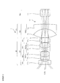
- FIG. 37 is a cross-sectional view including the first front group central axis Cf1 and the second front group central axis Cf2 of the optical system 1 of Example 9.
- FIG. 38 is a view as seen from the direction orthogonal to FIG. 39 and 40 are lateral aberration diagrams of the optical system 1 according to Example 9.
- FIG. 38 is a cross-sectional view including the first front group central axis Cf1 and the second front group central axis Cf2 of the optical system 1 of Example 9.
- FIG. 38 is a view as seen from the direction orthogonal to FIG. 39 and 40 are lateral aberration diagrams of the optical system 1 according to Example 9.
- the optical system 1 of Example 9 is arranged in parallel with the first front group center axis Cf1 having the first front group center axis Cf1 and the first front group center axis Cf1 in order from the object side to the image side.
- a rear deflection group Gbv arranged.
- the first front group Gf1 includes a first front first group Gf1 1 having a plano-concave negative lens Lf1 11 facing the object side, a cemented lens SUf1 21 of a biconcave negative lens Lf1 21 and a biconvex positive lens Lf1 22.
- the image side surface of the plano-concave negative lens Lf1 11 is an aspherical surface.
- the second front group Gf2 includes a second front first group Gf2 1 having a plano-concave negative lens Lf2 11 facing the object side, a cemented lens SUf2 21 of a biconcave negative lens Lf2 21 and a biconvex positive lens Lf2 22.
- the image side surface of the plano-concave negative lens Lf2 11 is aspheric.
- Rear group Gb is preferably provided with a first group Gb1 after having cemented lens SUB1 11 of the biconvex positive lens Lb 1 a biconcave negative lens Lb 2.
- the rear deflection group Gbv is disposed between the rear group Gb and the image plane I and includes a rear deflection member Lbv that deflects the first light beam L1 and the second light beam L2.
- the rear deflection member Lbv relaxes the convergence of the first light beam L1 and the second light beam L2 after exiting the rear group Gb, and the absolute values of the incident angles of the first light beam L1 and the second light beam L2 on the image plane I are reduced.
- Deflection is preferably performed so as to be smaller than the absolute value of the incident angle to the rear deflection group Gbv.
- the first light beam L1 incident on the first front group Gf1 from the first object surface is a plano-concave negative lens Lf1 11 of the first front first group Gf1 1 , a cemented lens SUf1 21 of the first front second group Gf1 2 , the first front
- the light passes through the cemented lens SUf1 31 of the third group Gf1 3 and the first diaphragm S1, exits the first front group Gf1, and then enters the rear group Gb.
- the second light beam L2 incident on the second front group Gf2 from the second object plane includes a plano-concave negative lens Lf2 11 of the second front first group Gf2 1 , a cemented lens SUf2 21 of the second front second group Gf2 2, a second front
- the light passes through the cemented lens SUf2 31 of the third group Gf2 3 and the second diaphragm S2, exits the second front group Gf2, and then enters the rear group Gb.
- the first light beam L1 and the second light beam L2 incident on the rear group Gb pass through the cemented lens SUb1 11 of the rear first group Gb1 and the rear deflection member Lbv of the rear deflection group Gbv, respectively, and enter the image plane.
- the rear deflection group Gbv includes a rear deflection member Lbv, and the rear deflection member Lbv moves rearward toward the outer peripheral side with respect to the rear group central axis Cb.
- This is an optical element having a large thickness in the group center axis Cb direction.
- the rear deflection group Gbv By configuring the rear deflection group Gbv with the rear deflection member Lbv having a refractive action, the rear deflection group Gbv can be formed by polishing or molding, and the productivity can be remarkably improved.
- the rear deflection member Lbv is a wedge prism-shaped optical element.
- both surfaces of the rear deflection member Lbv can be formed as a flat surface, and the productivity can be remarkably improved.
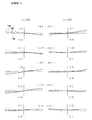
- FIG. 41 is a cross-sectional view including the first front group central axis Cf1 and the second front group central axis Cf2 of the optical system 1 of Example 10.
- FIG. 42 is a diagram viewed from a direction orthogonal to FIG. 43 and 44 are lateral aberration diagrams of the optical system 1 of Example 10.
- the optical system 1 of Example 10 is in parallel with the first front group Gf1 having the first front group center axis Cf1 and the first front group center axis Cf1 in order from the object side to the image side.
- a rear deflection group Gbv arranged.
- the first front group Gf1 includes a first front first group Gf1 1 having a plano-concave negative lens Lf1 11 facing the object side, a cemented lens SUf1 21 of a biconcave negative lens Lf1 21 and a biconvex positive lens Lf1 22.
- the image side surface of the plano-concave negative lens Lf1 11 is an aspherical surface.
- the second front group Gf2 includes a second front first group Gf2 1 having a plano-concave negative lens Lf2 11 facing the object side, a cemented lens SUf2 21 of a biconcave negative lens Lf2 21 and a biconvex positive lens Lf2 22.
- the image side surface of the plano-concave negative lens Lf2 11 is aspheric.
- Rear group Gb is preferably provided with a first group Gb1 after having cemented lens SUB1 11 of the negative meniscus lens Lb 2 having a convex surface directed toward the biconvex positive lens Lb 1 and the image plane I side.
- the rear deflection group Gbv is disposed between the rear group Gb and the image plane I, and has a rear deflection member Lbv that deflects the first light beam L1 and the second light beam L2.
- the rear deflection member Lbv relaxes the convergence of the first light beam L1 and the second light beam L2 after exiting the rear group Gb, and the absolute values of the incident angles of the first light beam L1 and the second light beam L2 on the image plane I are reduced.
- Deflection is preferably performed so as to be smaller than the absolute value of the incident angle to the rear deflection group Gbv.
- the first light beam L1 incident on the first front group Gf1 from the first object surface is a plano-concave negative lens Lf1 11 of the first front first group Gf1 1 , a cemented lens SUf1 21 of the first front second group Gf1 2 , the first front
- the light passes through the cemented lens SUf1 31 of the third group Gf1 3 and the first diaphragm S1, exits the first front group Gf1, and then enters the rear group Gb.
- the second light beam L2 incident on the second front group Gf2 from the second object plane includes a plano-concave negative lens Lf2 11 of the second front first group Gf2 1 , a cemented lens SUf2 21 of the second front second group Gf2 2, a second front
- the light passes through the cemented lens SUf2 31 of the third group Gf2 3 and the second diaphragm S2, exits the second front group Gf2, and then enters the rear group Gb.
- the first light beam L1 and the second light beam L2 incident on the rear group Gb pass through the cemented lens SUb1 11 of the rear first group Gb1 and the rear deflection member Lbv of the rear deflection group Gbv, respectively, and enter the image plane.
- the rear deflection group Gbv includes an optical element having a curved surface.
- the post-deflecting member Lbv includes a curved surface, so that the angle of the light beam incident on the image plane can be set more freely.
- the curved surface may be a spherical surface, a toric surface, an anamorphic surface, or a free-form surface.
- the rear deflection member Lbv can be arranged in any embodiment.
- the coordinate system is defined for each surface.
- the direction from the origin O of the coordinate system in which the surface is defined toward the image plane at each central axis is defined as the positive Z-axis direction.
- the direction from the second front group center axis Cf2 to the first front group center axis Cf1 on the same plane is defined as the X-axis positive direction.
- the positive Y-axis direction is defined by a right-handed coordinate system.
- optical action surfaces constituting the optical system of each embodiment, when a specific surface and a subsequent surface constitute a coaxial optical system, a surface interval is given.
- curvature radius of the surface, the medium Refractive index and Abbe number are given according to conventional methods.
- the amount of eccentricity from the origin O of the coordinate system in which the surface is defined (X-axis direction, Y-axis direction, and Z-axis direction are X, Y, Z, respectively) and the coordinate system defined by the origin O
- the tilt angles ( ⁇ , ⁇ , ⁇ (°), respectively) of the coordinate system defining each surface centered on the X axis, the Y axis, and the Z axis are given.
- positive ⁇ and ⁇ mean counterclockwise rotation with respect to the positive direction of each axis
- positive ⁇ means clockwise rotation with respect to the positive direction of the Z axis.
- the ⁇ , ⁇ , and ⁇ rotations of the central axis of the surface are performed by rotating the coordinate system defining each surface counterclockwise around the X axis of the coordinate system defined at the origin of the optical system. Then rotate it around the Y axis of the new rotated coordinate system by ⁇ and then rotate it around the Z axis of another rotated new coordinate system by ⁇ . It is.
- Refractive index and Abbe number are shown for d-line (wavelength 587.56 nm).
- the unit of length is mm.
- the eccentricity of each surface is expressed by the amount of eccentricity from the reference surface. “ ⁇ ” described in the radius of curvature indicates infinite.
- the aspheric data used in the present embodiment includes data relating to the aspherical lens surface in the surface data.
- the aspherical shape is expressed by the following formula (a), where z is an optical axis with the light traveling direction being positive, and y is a direction orthogonal to the optical axis.
- z (y 2 / r) / [1+ ⁇ 1 ⁇ (1 + K) ⁇ (y / r) 2 ⁇ 1/2 ] + A4y 4 + A6y 6 + A8y 8 + A10y 10 ... (a)
- r is a paraxial radius of curvature
- K is a conical coefficient
- A4, A6, and A8 are fourth-order, sixth-order, and eighth-order aspheric coefficients, respectively.
- the symbol “e” indicates that the subsequent numerical value is a power exponent with 10 as the base. For example, “1.0e-5” means “1.0 ⁇ 10 ⁇ 5 ”.
- the shape of the free-form surface FFS used in this embodiment is defined by the following equation (b).
- Z in the definition formula is the Z axis of the free-form surface FFS.
- the coefficient term for which no data is described is zero.
- the definition formula (b) is shown as an example as described above, and the free-form surface of the present invention uses a rotationally asymmetric surface to correct rotationally asymmetric aberration caused by decentration.
- the feature is that the manufacturability is also improved, and it goes without saying that the same effect can be obtained for any other defining formula.
- Example 8 Surface number Curvature radius Surface spacing Eccentricity Refractive index Abbe number Object surface ⁇ 20.000 1 ⁇ 0.500 1.8830 40.7 2 Aspherical surface [1] 1.439 3 -39.792 0.500 1.8830 40.7 4 1.534 0.900 1.7847 25.7 5 -4.963 0.100 6 4.316 0.500 1.9229 18.9 7 1.596 0.900 1.5831 59.4 8 -1.806 0.050 9 Aperture surface 0.000 10 Reference surface 0.000 Eccentricity (1) 11 2.834 1.200 1.5831 59.4 12 -46.290 0.878 13 -40.929 0.600 1.9229 18.9 14 5.915 0.383 15 ⁇ 1.100 Eccentricity (2) 1.5163 64.1 16 ⁇ 0.150 Eccentricity (3) Image plane ⁇ Eccentricity (3) Aspherical [1] Curvature radius 0.717 k -2.2311e-001 Eccentric [1] X 1.000 Y 0.000 Z 0.000 ⁇ 0.000 ⁇ 0.000 ⁇ 0.000 Eccentric [2
- Example 2 Example 3
- Example 4 (1) FAb / f 15.723 12.444 7.805 36.816
- Example 6 Example 7
- Example 8 (1) FAb / f 12.491 4.524 4.459 9.951
- Example 10 (1) FAb / f 11.964 9.239 (2) Lb / f 3.418 2.788
- FIG. 45 is a diagram illustrating an example in which the optical system according to the present embodiment is used as an imaging device for an automobile.
- FIG. 45 (a) shows an image obtained by attaching the optical system 1 according to the present embodiment as an imaging device in front of the automobile 130, and performing image processing on an image captured through each optical system 1 on a display device in the vehicle.
- FIG. 45 (b) shows a plurality of optical systems 1 according to the present embodiment as imaging devices at the corners of the automobile 130 and the top of the poles of the head unit. It is a figure which shows the example which attached and attached the image image
- FIG. 46 is a diagram illustrating an example in which the optical system according to the present embodiment is used as a photographing optical system at the distal end of an endoscope.
- FIG. 46 is a diagram for illustrating an example in which the optical system 1 according to the present embodiment is used as a photographing optical system at the tip of an endoscope.
- FIG. 46A is an example in which the optical system 1 according to the present embodiment is attached to the distal end of the rigid endoscope 110 and 360 ° omnidirectional images are imaged and observed.
- FIG. 46B shows a schematic configuration of the tip.
- FIG. 46 (c) shows that the optical system 1 according to the present embodiment is similarly attached to the tip of the flexible electronic endoscope 113, and the captured image is processed on the display device 114. This is an example in which distortion is corrected and displayed in three dimensions.
Landscapes
- Physics & Mathematics (AREA)
- Optics & Photonics (AREA)
- Health & Medical Sciences (AREA)
- General Physics & Mathematics (AREA)
- Life Sciences & Earth Sciences (AREA)
- Surgery (AREA)
- Astronomy & Astrophysics (AREA)
- General Health & Medical Sciences (AREA)
- Radiology & Medical Imaging (AREA)
- Pathology (AREA)
- Public Health (AREA)
- Heart & Thoracic Surgery (AREA)
- Medical Informatics (AREA)
- Molecular Biology (AREA)
- Animal Behavior & Ethology (AREA)
- Engineering & Computer Science (AREA)
- Biomedical Technology (AREA)
- Veterinary Medicine (AREA)
- Nuclear Medicine, Radiotherapy & Molecular Imaging (AREA)
- Biophysics (AREA)
- Lenses (AREA)
- Endoscopes (AREA)
- Instruments For Viewing The Inside Of Hollow Bodies (AREA)
- Stereoscopic And Panoramic Photography (AREA)
Priority Applications (3)
| Application Number | Priority Date | Filing Date | Title |
|---|---|---|---|
| CN201480073186.1A CN105917263B (zh) | 2014-01-15 | 2014-10-08 | 光学系统、立体摄像装置和内窥镜 |
| EP14878996.9A EP3096168A4 (en) | 2014-01-15 | 2014-10-08 | Optical system, stereoscopic image pickup device, and endoscope |
| US15/208,653 US10274717B2 (en) | 2014-01-15 | 2016-07-13 | Optical system, stereoscopic imaging device, and endoscope |
Applications Claiming Priority (2)
| Application Number | Priority Date | Filing Date | Title |
|---|---|---|---|
| JP2014005019A JP6280749B2 (ja) | 2013-01-23 | 2014-01-15 | 光学系、立体撮像装置、及び内視鏡 |
| JP2014-005019 | 2014-01-15 |
Related Child Applications (1)
| Application Number | Title | Priority Date | Filing Date |
|---|---|---|---|
| US15/208,653 Continuation US10274717B2 (en) | 2014-01-15 | 2016-07-13 | Optical system, stereoscopic imaging device, and endoscope |
Publications (1)
| Publication Number | Publication Date |
|---|---|
| WO2015107733A1 true WO2015107733A1 (ja) | 2015-07-23 |
Family
ID=53545011
Family Applications (1)
| Application Number | Title | Priority Date | Filing Date |
|---|---|---|---|
| PCT/JP2014/076968 Ceased WO2015107733A1 (ja) | 2014-01-15 | 2014-10-08 | 光学系、立体撮像装置、及び内視鏡 |
Country Status (5)
| Country | Link |
|---|---|
| US (1) | US10274717B2 (enExample) |
| EP (1) | EP3096168A4 (enExample) |
| JP (1) | JP6280749B2 (enExample) |
| CN (1) | CN105917263B (enExample) |
| WO (1) | WO2015107733A1 (enExample) |
Cited By (2)
| Publication number | Priority date | Publication date | Assignee | Title |
|---|---|---|---|---|
| WO2017187814A1 (ja) * | 2016-04-25 | 2017-11-02 | オリンパス株式会社 | 内視鏡対物光学系 |
| US10520719B2 (en) | 2015-08-21 | 2019-12-31 | Olympus Corporation | Image acquisition device |
Families Citing this family (18)
| Publication number | Priority date | Publication date | Assignee | Title |
|---|---|---|---|---|
| JP6150717B2 (ja) * | 2013-12-05 | 2017-06-21 | オリンパス株式会社 | 立体撮像光学系、立体撮像装置及び内視鏡 |
| EP3252514A4 (en) * | 2015-01-26 | 2018-08-22 | Hitachi Automotive Systems, Ltd. | Imaging lens, imaging device using same, and distance measuring system |
| CN108369369B (zh) | 2015-12-14 | 2020-11-17 | 奥林巴斯株式会社 | 摄像装置 |
| JP6704413B2 (ja) * | 2015-12-17 | 2020-06-03 | オリンパス株式会社 | 内視鏡用光学アダプタ |
| US10295817B2 (en) * | 2016-06-01 | 2019-05-21 | General Electric Company | Stereo imaging system |
| WO2018189853A1 (ja) | 2017-04-13 | 2018-10-18 | オリンパス株式会社 | 立体視内視鏡光学系及びそれを備えた内視鏡 |
| WO2018211595A1 (ja) | 2017-05-16 | 2018-11-22 | オリンパス株式会社 | 立体視用光学系及びそれを備えた撮像装置 |
| WO2018225397A1 (ja) * | 2017-06-06 | 2018-12-13 | オリンパス株式会社 | 立体内視鏡 |
| WO2019008618A1 (ja) | 2017-07-03 | 2019-01-10 | オリンパス株式会社 | 立体視用光学系及びそれを備えた撮像装置 |
| JP2019056722A (ja) * | 2017-09-19 | 2019-04-11 | パナソニックIpマネジメント株式会社 | 斜視内視鏡及び撮像システム |
| WO2019064515A1 (ja) | 2017-09-29 | 2019-04-04 | オリンパス株式会社 | 立体視用光学系及びそれを備えた撮像装置 |
| WO2019106898A1 (ja) | 2017-11-30 | 2019-06-06 | オリンパス株式会社 | 立体視光学系及びそれを備えた内視鏡 |
| US11857151B2 (en) * | 2018-09-12 | 2024-01-02 | Steris Instrument Management Services, Inc. | Systems and methods for standalone endoscopic objective image analysis |
| WO2020110233A1 (ja) | 2018-11-28 | 2020-06-04 | オリンパス株式会社 | 1組の負メニスカスレンズ、広角光学系、撮像装置、及び投影装置 |
| WO2020225924A1 (ja) | 2019-05-09 | 2020-11-12 | オリンパス株式会社 | 広角光学系、撮像装置、及び撮像システム |
| CN110200574B (zh) * | 2019-06-27 | 2022-02-18 | 京东方科技集团股份有限公司 | 内窥镜成像装置 |
| CN117676294A (zh) * | 2022-08-09 | 2024-03-08 | 晋城三赢精密电子有限公司 | 摄像头模组及电子产品 |
| DE102024116457A1 (de) * | 2024-06-12 | 2025-12-18 | Schölly Fiberoptic GmbH | Chip-in-tip-Endoskop mit verbesserter 3D-Sicht |
Citations (6)
| Publication number | Priority date | Publication date | Assignee | Title |
|---|---|---|---|---|
| JPH0856891A (ja) * | 1994-08-23 | 1996-03-05 | Olympus Optical Co Ltd | 立体視硬性内視鏡 |
| JPH08122665A (ja) | 1994-10-27 | 1996-05-17 | Olympus Optical Co Ltd | 立体視内視鏡 |
| JP2001147382A (ja) | 1999-11-19 | 2001-05-29 | Olympus Optical Co Ltd | 内視鏡用対物光学系 |
| JP2003005096A (ja) * | 2001-06-27 | 2003-01-08 | Olympus Optical Co Ltd | 内視鏡装置 |
| JP4093503B2 (ja) | 1997-06-13 | 2008-06-04 | フジノン株式会社 | 立体視内視鏡 |
| WO2014147856A1 (ja) * | 2013-03-22 | 2014-09-25 | オリンパス株式会社 | 立体撮像光学系、立体撮像装置及び内視鏡 |
Family Cites Families (17)
| Publication number | Priority date | Publication date | Assignee | Title |
|---|---|---|---|---|
| US2268338A (en) * | 1938-02-25 | 1941-12-30 | Zeiss Ikon Ag | Stereoscopic attachment for projectors |
| JPS63294509A (ja) * | 1987-05-27 | 1988-12-01 | Olympus Optical Co Ltd | 立体視内視鏡装置 |
| US5459605A (en) * | 1992-12-17 | 1995-10-17 | Paul S. Kempf | 3-D endoscope apparatus |
| JPH0829701A (ja) * | 1994-07-18 | 1996-02-02 | Olympus Optical Co Ltd | 立体視内視鏡システム |
| US6104426A (en) * | 1996-03-23 | 2000-08-15 | Street; Graham S. B. | Stereo-endoscope |
| DE10027166B4 (de) * | 1999-05-31 | 2007-03-08 | Pentax Corp. | Stereoskopmikroskop |
| JP2001221961A (ja) * | 2000-02-09 | 2001-08-17 | Olympus Optical Co Ltd | 双眼光学アダプタ |
| JP3516634B2 (ja) * | 2000-05-30 | 2004-04-05 | 日本電気株式会社 | サーキットエミュレーション装置及びサーキットエミュレーション装置における多重化方法 |
| JP2005241791A (ja) * | 2004-02-25 | 2005-09-08 | Olympus Corp | ステレオ撮像装置 |
| DE102005036486A1 (de) * | 2005-07-20 | 2007-01-25 | Leica Microsystems (Schweiz) Ag | Optisches Gerät mit erhöhter Schärfentiefe |
| JP4750175B2 (ja) * | 2008-11-28 | 2011-08-17 | オリンパスメディカルシステムズ株式会社 | ステレオ光学系、並びにそれを用いたステレオ計測用光学装置、ステレオ計測装置及びステレオ観察装置 |
| WO2012017684A1 (ja) * | 2010-08-06 | 2012-02-09 | パナソニック株式会社 | レンズユニット |
| JP2012220848A (ja) * | 2011-04-12 | 2012-11-12 | Nikon Corp | 撮像装置及びレンズ装置 |
| KR20130011200A (ko) * | 2011-07-20 | 2013-01-30 | 삼성전자주식회사 | 3차원 영상 촬영 렌즈계 및 이를 구비한 촬영장치 |
| JP2013109009A (ja) * | 2011-11-17 | 2013-06-06 | Canon Inc | 立体映像撮影用光学装置および立体映像撮影装置 |
| JP5427323B2 (ja) | 2012-01-18 | 2014-02-26 | オリンパスメディカルシステムズ株式会社 | 立体視内視鏡用光学系 |
| JP6280803B2 (ja) * | 2014-04-24 | 2018-02-14 | オリンパス株式会社 | 立体撮像用光学系、立体撮像装置、及び内視鏡 |
-
2014
- 2014-01-15 JP JP2014005019A patent/JP6280749B2/ja not_active Expired - Fee Related
- 2014-10-08 WO PCT/JP2014/076968 patent/WO2015107733A1/ja not_active Ceased
- 2014-10-08 EP EP14878996.9A patent/EP3096168A4/en not_active Withdrawn
- 2014-10-08 CN CN201480073186.1A patent/CN105917263B/zh not_active Expired - Fee Related
-
2016
- 2016-07-13 US US15/208,653 patent/US10274717B2/en active Active
Patent Citations (7)
| Publication number | Priority date | Publication date | Assignee | Title |
|---|---|---|---|---|
| JPH0856891A (ja) * | 1994-08-23 | 1996-03-05 | Olympus Optical Co Ltd | 立体視硬性内視鏡 |
| JPH08122665A (ja) | 1994-10-27 | 1996-05-17 | Olympus Optical Co Ltd | 立体視内視鏡 |
| JP4093503B2 (ja) | 1997-06-13 | 2008-06-04 | フジノン株式会社 | 立体視内視鏡 |
| JP2001147382A (ja) | 1999-11-19 | 2001-05-29 | Olympus Optical Co Ltd | 内視鏡用対物光学系 |
| JP2003005096A (ja) * | 2001-06-27 | 2003-01-08 | Olympus Optical Co Ltd | 内視鏡装置 |
| JP4248771B2 (ja) | 2001-06-27 | 2009-04-02 | オリンパス株式会社 | 内視鏡装置 |
| WO2014147856A1 (ja) * | 2013-03-22 | 2014-09-25 | オリンパス株式会社 | 立体撮像光学系、立体撮像装置及び内視鏡 |
Non-Patent Citations (1)
| Title |
|---|
| See also references of EP3096168A4 |
Cited By (3)
| Publication number | Priority date | Publication date | Assignee | Title |
|---|---|---|---|---|
| US10520719B2 (en) | 2015-08-21 | 2019-12-31 | Olympus Corporation | Image acquisition device |
| WO2017187814A1 (ja) * | 2016-04-25 | 2017-11-02 | オリンパス株式会社 | 内視鏡対物光学系 |
| JPWO2017187814A1 (ja) * | 2016-04-25 | 2018-05-10 | オリンパス株式会社 | 内視鏡対物光学系 |
Also Published As
| Publication number | Publication date |
|---|---|
| CN105917263B (zh) | 2019-04-23 |
| US10274717B2 (en) | 2019-04-30 |
| JP2014160240A (ja) | 2014-09-04 |
| CN105917263A (zh) | 2016-08-31 |
| US20160320606A1 (en) | 2016-11-03 |
| EP3096168A1 (en) | 2016-11-23 |
| EP3096168A4 (en) | 2017-08-02 |
| JP6280749B2 (ja) | 2018-02-14 |
Similar Documents
| Publication | Publication Date | Title |
|---|---|---|
| JP6280749B2 (ja) | 光学系、立体撮像装置、及び内視鏡 | |
| US11252394B2 (en) | Lens apparatus and imaging apparatus including the same | |
| JP6261566B2 (ja) | 立体撮像光学系、立体撮像装置及び内視鏡 | |
| US20100195214A1 (en) | Zoom lens, optical apparatus equipped therewith and method for manufacturing the zoom lens | |
| JP2014174390A (ja) | 結像光学系、立体撮像装置、及び内視鏡 | |
| JP7061226B2 (ja) | 広角光学系及びそれを備えた撮像装置 | |
| CN105814471B (zh) | 广角光学系统和内窥镜 | |
| WO2017022670A1 (ja) | 接眼光学系および電子ビューファインダー | |
| CN112394495B (zh) | 成像镜头及摄像装置 | |
| JP6150717B2 (ja) | 立体撮像光学系、立体撮像装置及び内視鏡 | |
| CN106233182B (zh) | 立体摄像用光学系统、立体摄像装置以及内窥镜 | |
| US20130163092A1 (en) | Endoscope Objective Optical System | |
| JP6000823B2 (ja) | 光学素子、光学系、立体撮像装置、及び内視鏡 | |
| WO2017033234A1 (ja) | 撮像装置 | |
| JP5629996B2 (ja) | 立体視光学装置および結像光学装置 | |
| US20230251460A1 (en) | Stereoscopic optical system and image pickup apparatus | |
| JP2017097198A (ja) | 広角レンズ及び撮像装置 | |
| JP7154903B2 (ja) | レンズ装置およびそれを有する撮像装置 | |
| US11320646B2 (en) | Eyepiece lens and optical apparatus | |
| JP2014026001A (ja) | アタッチメント光学系 | |
| CN112334811A (zh) | 物镜光学系统及使用了该物镜光学系统的硬性镜用光学系统、硬性镜 |
Legal Events
| Date | Code | Title | Description |
|---|---|---|---|
| 121 | Ep: the epo has been informed by wipo that ep was designated in this application |
Ref document number: 14878996 Country of ref document: EP Kind code of ref document: A1 |
|
| NENP | Non-entry into the national phase |
Ref country code: DE |
|
| REEP | Request for entry into the european phase |
Ref document number: 2014878996 Country of ref document: EP |
|
| WWE | Wipo information: entry into national phase |
Ref document number: 2014878996 Country of ref document: EP |