WO2015107733A1 - 光学系、立体撮像装置、及び内視鏡 - Google Patents
光学系、立体撮像装置、及び内視鏡 Download PDFInfo
- Publication number
- WO2015107733A1 WO2015107733A1 PCT/JP2014/076968 JP2014076968W WO2015107733A1 WO 2015107733 A1 WO2015107733 A1 WO 2015107733A1 JP 2014076968 W JP2014076968 W JP 2014076968W WO 2015107733 A1 WO2015107733 A1 WO 2015107733A1
- Authority
- WO
- WIPO (PCT)
- Prior art keywords
- group
- optical system
- front group
- light beam
- lens
- Prior art date
Links
Images


Classifications
-
- G—PHYSICS
- G02—OPTICS
- G02B—OPTICAL ELEMENTS, SYSTEMS OR APPARATUS
- G02B23/00—Telescopes, e.g. binoculars; Periscopes; Instruments for viewing the inside of hollow bodies; Viewfinders; Optical aiming or sighting devices
- G02B23/24—Instruments or systems for viewing the inside of hollow bodies, e.g. fibrescopes
- G02B23/2407—Optical details
- G02B23/2415—Stereoscopic endoscopes
-
- A—HUMAN NECESSITIES
- A61—MEDICAL OR VETERINARY SCIENCE; HYGIENE
- A61B—DIAGNOSIS; SURGERY; IDENTIFICATION
- A61B1/00—Instruments for performing medical examinations of the interior of cavities or tubes of the body by visual or photographical inspection, e.g. endoscopes; Illuminating arrangements therefor
- A61B1/00163—Optical arrangements
- A61B1/00193—Optical arrangements adapted for stereoscopic vision
-
- A—HUMAN NECESSITIES
- A61—MEDICAL OR VETERINARY SCIENCE; HYGIENE
- A61B—DIAGNOSIS; SURGERY; IDENTIFICATION
- A61B1/00—Instruments for performing medical examinations of the interior of cavities or tubes of the body by visual or photographical inspection, e.g. endoscopes; Illuminating arrangements therefor
- A61B1/00163—Optical arrangements
- A61B1/00194—Optical arrangements adapted for three-dimensional imaging
-
- G—PHYSICS
- G02—OPTICS
- G02B—OPTICAL ELEMENTS, SYSTEMS OR APPARATUS
- G02B13/00—Optical objectives specially designed for the purposes specified below
- G02B13/001—Miniaturised objectives for electronic devices, e.g. portable telephones, webcams, PDAs, small digital cameras
-
- G—PHYSICS
- G02—OPTICS
- G02B—OPTICAL ELEMENTS, SYSTEMS OR APPARATUS
- G02B23/00—Telescopes, e.g. binoculars; Periscopes; Instruments for viewing the inside of hollow bodies; Viewfinders; Optical aiming or sighting devices
- G02B23/16—Housings; Caps; Mountings; Supports, e.g. with counterweight
- G02B23/18—Housings; Caps; Mountings; Supports, e.g. with counterweight for binocular arrangements
-
- G—PHYSICS
- G02—OPTICS
- G02B—OPTICAL ELEMENTS, SYSTEMS OR APPARATUS
- G02B23/00—Telescopes, e.g. binoculars; Periscopes; Instruments for viewing the inside of hollow bodies; Viewfinders; Optical aiming or sighting devices
- G02B23/24—Instruments or systems for viewing the inside of hollow bodies, e.g. fibrescopes
- G02B23/2407—Optical details
- G02B23/2423—Optical details of the distal end
- G02B23/243—Objectives for endoscopes
-
- G—PHYSICS
- G02—OPTICS
- G02B—OPTICAL ELEMENTS, SYSTEMS OR APPARATUS
- G02B27/00—Optical systems or apparatus not provided for by any of the groups G02B1/00 - G02B26/00, G02B30/00
- G02B27/0025—Optical systems or apparatus not provided for by any of the groups G02B1/00 - G02B26/00, G02B30/00 for optical correction, e.g. distorsion, aberration
-
- G—PHYSICS
- G03—PHOTOGRAPHY; CINEMATOGRAPHY; ANALOGOUS TECHNIQUES USING WAVES OTHER THAN OPTICAL WAVES; ELECTROGRAPHY; HOLOGRAPHY
- G03B—APPARATUS OR ARRANGEMENTS FOR TAKING PHOTOGRAPHS OR FOR PROJECTING OR VIEWING THEM; APPARATUS OR ARRANGEMENTS EMPLOYING ANALOGOUS TECHNIQUES USING WAVES OTHER THAN OPTICAL WAVES; ACCESSORIES THEREFOR
- G03B35/00—Stereoscopic photography
- G03B35/08—Stereoscopic photography by simultaneous recording
- G03B35/10—Stereoscopic photography by simultaneous recording having single camera with stereoscopic-base-defining system
Definitions
- the present invention relates to an optical system, a stereoscopic imaging apparatus, and an endoscope.
- Patent Documents 1 to 4 Conventionally, a method has been disclosed in which two images with different parallax are imaged on a substantially identical plane for stereoscopic viewing (see Patent Documents 1 to 4).
- JP-A-8-122665 Japanese Patent No. 42488771 Japanese Patent No. 4093503 JP 2001-147382 A
- Patent Documents 1 to 3 are configured by an optical system in which the object side has two optical axes and the image side has one optical axis. Moreover, the technique described in Patent Document 4 is configured with two optical axes from an object to an image. Neither of these technologies can cope with the recent high resolution.
- the present invention has been made in view of the above-described circumstances, and provides an optical system, a stereoscopic imaging apparatus, and an endoscope that can obtain a small and high-resolution stereoscopic image with a wide viewing angle of view.
- the purpose is that.
- An optical system includes: From the object side, A front group having a first front group centered on a first front group central axis and a second front group centered on a second front group central axis parallel to the first front group central axis; A rear group centered on a single rear group central axis; With The central principal ray of the first light beam that has passed through the first front group and the central principal ray of the second light beam that has passed through the second front group do not intersect each other until they reach the image plane after exiting the rear group. It is characterized by.
- the first light flux and the second light flux are convergent lights that do not intersect each other until they reach the image plane after exiting the rear group.
- the distance between the first front group central axis and the second front group central axis is wider than the distance between the center of the first light flux on the image plane and the center of the second light flux on the image plane.
- a rear deflection group disposed between the rear group and the image plane for deflecting the first and second light beams;
- the rear deflection group relaxes convergence of the first light beam and the second light beam after exiting the rear group, and an absolute value of an incident angle of the first light beam and the second light beam on the image plane is determined. Deflection is performed so as to be smaller than the absolute value of the incident angle to the rear deflection group.
- the rear deflection group includes a first rear deflection group that deflects the first light beam and a second rear deflection group that deflects the second light beam.
- the rear deflection group includes a rear deflection member,
- the rear deflection member is an optical element having a thickness in the rear central axis direction that increases toward the outer peripheral side with respect to the rear central axis.
- the rear deflection member is a wedge prism-shaped optical element.
- the rear deflection member includes a curved surface.
- the rear deflection group includes a diffractive optical element.
- the first front group and the second front group in order from the object side to the image plane side, respectively, the front one group having negative refractive power, Two front groups including a positive cemented lens;
- the front group 1 includes a plano-concave negative lens having a plane facing the object side
- the front two groups of cemented lenses are composed of positive cemented meniscus lenses having a convex surface facing the object side.
- An optical system includes: The first front group and the second front group each have three front groups including positive cemented lenses different from the second group on the rear group side of the second group.
- An optical system includes: The following conditional expression (1) is satisfied.
- FAb is the distance from the last surface of the front group to the imaging position where the light beam exiting the front group forms an image
- f is the focal length of the entire optical system.
- An optical system includes: The following conditional expression (2) is satisfied. Lb / f ⁇ 5 (2) However, Lb is the distance from the last surface of the rear group to the image plane, f is the focal length of the entire optical system.
- An optical system includes: A light blocking member disposed in the first front group for blocking the first light flux; A pupil division member arranged in a second front group and deflecting the second light flux; Is provided.
- An optical system includes:
- the deflection member is A first pupil that forms an image without deflecting a part of the second luminous flux;
- a second pupil that forms an image of the other part of the second light flux at a different position on the same plane as the position at which the first pupil forms an image;
- An optical system includes: The pupil dividing member has a positive refractive power, An imaging position at a near point that does not use the pupil dividing member and an imaging position at a far point that uses the pupil dividing member are the same.
- An optical system includes: The light shielding member and the pupil dividing member are disposed between the corresponding lenses of the first front group and the second front group, respectively.
- a stereoscopic imaging apparatus includes the optical system and an imaging element.
- the imaging element is a single element.
- An endoscope according to an embodiment of the present invention includes the stereoscopic imaging device.
- the optical system, the stereoscopic imaging apparatus, and the endoscope which are the embodiments of the present invention, it is possible to obtain a small and high-resolution stereoscopic image with a wide observation angle of view.
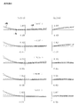
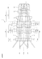
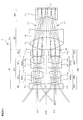
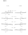
- FIG. 2 is a cross-sectional view along the central axis C of the optical system 1 of Example 1.
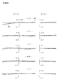
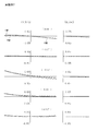
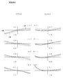
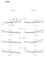
- FIG. 2 is a lateral aberration diagram of the optical system 1 of Example 1.
- FIG. 6 is a cross-sectional view along the central axis C of the optical system 1 of Example 2.
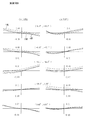
- 6 is a lateral aberration diagram of the optical system 1 of Example 2.
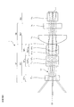
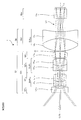
- FIG. 6 is a cross-sectional view taken along the central axis C of the optical system 1 of Example 3.
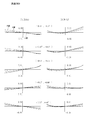
- FIG. 6 is a lateral aberration diagram of the optical system 1 according to Example 3.
- FIG. FIG. 6 is a cross-sectional view along the central axis C of the optical system 1 of Example 4.
- 6 is a lateral aberration diagram of the optical system 1 according to Example 4.
- FIG. FIG. 10 is a cross-sectional view along the central axis C of the optical system 1 of Example 5.
- 6 is a lateral aberration diagram of the optical system 1 according to Example 5.
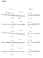
- FIG. FIG. 12 is a cross-sectional view along the central axis C of the optical system 1 during far-point observation in Example 6.
- FIG. 10 is a cross-sectional view taken along the central axis C of the optical system 1 during near-point observation in Example 6.
- FIG. 10 is a lateral aberration diagram of the optical system 1 during far-point observation according to Example 6.
- FIG. FIG. 25 is a lateral aberration diagram for the deflected first light beam L1 'that passes through the first pupil E1 of the optical system 1 during the near-point observation according to the sixth example.
- 22 is a lateral aberration diagram for the deflected second light beam L2 ′ that passes through the second pupil E2 of the optical system 1 during the near-point observation in Example 6.
- FIG. FIG. 10 is a cross-sectional view along the central axis C of the optical system 1 during far-point observation in Example 7.
- FIG. 10 is a cross-sectional view taken along the central axis C of the optical system 1 during near-point observation in Example 7.
- FIG. 10 is a lateral aberration diagram of the optical system 1 during far-point observation in Example 7.
- FIG. FIG. 25 is a lateral aberration diagram for the deflected first light beam L1 'that passes through the first pupil E1 of the optical system 1 during the near-point observation according to the seventh embodiment.
- FIG. 25 is a lateral aberration diagram for the deflected second light beam L2 'that passes through the second pupil E2 of the optical system 1 during the near-point observation according to the seventh embodiment.
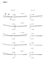
- FIG. 10 is a cross-sectional view including a first front group center axis Cf1 and a second front group center axis Cf2 of the optical system 1 of Example 8. It is the figure seen from the direction orthogonal to FIG.
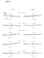
- FIG. 10 is a lateral aberration diagram of the optical system 1 according to Example 8.
- FIG. 10 is a lateral aberration diagram of the optical system 1 according to Example 8.
- FIG. 10 is a cross-sectional view including a first front group center axis Cf1 and a second front group center axis Cf2 of the optical system 1 of Example 9. It is the figure seen from the direction orthogonal to FIG. 10 is a lateral aberration diagram of the optical system 1 according to Example 8.
- FIG. 10 is a lateral aberration diagram of the optical system 1 according to Example 8.
- FIG. FIG. 22 is a cross-sectional view including a first front group center axis Cf1 and a second front group center axis Cf2 of the optical system 1 of Example 10.
- FIG. 10 is a lateral aberration diagram of the optical system 1 according to Example 8.
- FIG. 10 is a lateral aberration diagram of the optical system 1 according to Example 8.
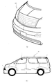
- FIG. It is a figure which shows the example which used the optical system of this embodiment as an imaging device of a motor vehicle. It is a figure which shows the example which used the optical system of this embodiment as an imaging
- optical system 1 of this embodiment will be described.
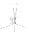
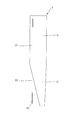
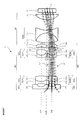
- FIG. 1 is a cross-sectional view taken along a central axis C of an optical system 1 according to an embodiment of the present invention.
- the optical system 1 of the present embodiment is arranged in order from the object side with a first front group center axis Cf2 parallel to the first front group center axis Cf1 and the first front group center axis Cf1 centered on the first front group center axis Cf1.
- the central chief rays of the second light beam L2 that has passed through the second front group Gf2 are preferably convergent lights that do not cross each other until they reach the image plane I after exiting the rear group Gb.
- the first light beam L1 and the second light beam L2 are preferably convergent lights that do not intersect each other until they reach the image plane I after exiting the rear group Gb.
- the stereoscopic imaging system has the following four patterns. 1. An optical system consisting of two completely independent central axes. 2. An optical system comprising a front group of one central axis and a rear group of two central axes from the object side. 3. An optical system comprising a front group of two central axes and a rear group of one central axis from the object side. 4). The whole optical system obtains parallax by pupil division with one central axis.
- This type of optical system is a type that is often employed in small three-dimensional imaging devices, but has a drawback that the total length becomes long.
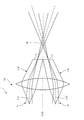
- FIG. 2 is a view showing the vicinity of the image plane I of the optical system 1 according to an embodiment of the present invention.
- FIG. 47 is a view showing the vicinity of the image plane of the optical system as a reference example. 2 and 47 schematically show the rear group Gb.
- the optical system 1 of this embodiment shown in FIG. 2 and the optical system 100 of the reference example shown in FIG. 47 are composed of a front group and a rear group Gb (not shown) in order from the object side. 2 and 47, the left side is the front side and the right side is the rear side.
- the luminous flux enters the rear group Gb in parallel from the front group of two optical axes (not shown).
- the first central principal ray Lc1 and the second central principal ray Lc2 of the first light flux L1 and the second light flux L2 that are parallel to each other pass through the rear group Gb, and then intersect at a position behind the rear group Gb. This is because the focal position f0 of the incident first light beam L1 and second light beam L2 is a rear position of the rear group Gb. If each of the axial light beams L10 and L20 exiting the front group is parallel light, the images of the first light beam L1 and the second light beam L2 are formed to overlap with the focal position f0 on the rear side of the rear group Gb. Therefore, stereoscopic imaging cannot be performed.
- the optical system 100 of the reference example shown in FIG. 47 is configured to form an image further behind the focal position f0 by diverging each of the axial light beams L10 and L20 emitted from the front group.
- the imaging plane I 1 and the second imaging plane I 2 are arranged side by side. This method is effective when it is desired to make the image size relatively large, and it is possible to form an image as much as possible by increasing the distance from the rear group Gb to the imaging surfaces I 1 and I 2. It becomes. In this case, since the optical paths intersect each other, it is possible to ensure a large imaging surface without increasing the outer diameter of the optical system 100.
- the left and right images are successfully imaged side by side by forming an image before the focal position f0 on the rear side of the rear group Gb.
- the first central chief ray Lc1 and the second central chief ray Lc2 exiting the front group are in the focal position f0 on the rear side of the rear group Gb, as in the reference example shown in FIG. Cross at.
- the optical paths do not intersect before the first imaging plane I 1 and the second imaging plane I 2 .
- the axial light beams L10 and L20 exiting the front group are converged, contrary to the reference example shown in FIG. It is important to.
- the arrangement in which the image is formed at a position closer to the rear group Gb than the focal position f0 on the rear side of the rear group Gb makes it possible to reduce the size of the imaging surfaces I 1 and I 2. Compatibility with is improved. Furthermore, the distance from the rear group Gb to the imaging planes I 1 and I 2 can be significantly shortened as compared with the prior art, and the overall length of the apparatus using the optical system 1 and the optical system 1 is shortened. It becomes possible.
- the distance between the first front group central axis Cf1 and the second front group center axis Cf2 is the same as the first central principal ray Lc1 of the first light beam L1 on the image plane I. It is wider than the interval of the second central principal ray Lc2 of the second light beam L2 on the image plane I.
- the image center interval is preferably narrower than the entrance pupil interval of the optical system.
- the optical axis In the case of stereoscopic viewing at an object point distance of several millimeters to several hundred millimeters, in order to obtain a stereoscopic image that looks natural, it is preferable to give a parallax amount when a human observes with both eyes at normal times. For example, the convergence angle when an observer with a distance of 50 cm and an eye width of 6 cm is stereoscopically viewed is about 7 °. Therefore, in order to obtain the same convergence angle in a stereoscopic imaging optical system that performs magnification observation at a distance of 15 mm, the optical axis The distance needs to be close to about 1.8 mm.
- the Fno of the optical system becomes large, and it is difficult to perform high-resolution imaging.
- the image center interval is narrower than the entrance pupil interval so as to be compatible with a small-sized and high-pixel imaging device.
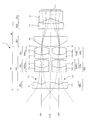
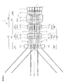
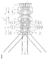
- FIG. 3 is a cross-sectional view taken along the central axis C of the optical system 1 of one embodiment having a rear deflection group according to the present invention.
- a rear deflection group Gbv that is disposed between the rear group Gb and the image plane I and deflects the first light beam L1 and the second light beam L2, and the rear deflection group Gbv emits the rear group Gb.
- the convergence of the subsequent first light beam L1 and the second light beam L2 is relaxed, and the absolute values of the incident angles of the first light beam L1 and the second light beam L2 on the image plane I are smaller than the absolute values of the incident angles on the rear deflection group Gbv. It is preferable to deflect so as to be small.
- the first light beam L1 and the second light beam L2 exit each front group Gf in a convergent manner and form an image on the image plane I in front of each focal position.
- L2 is incident obliquely on the image plane I.
- Recent high-resolution and high-sensitivity imaging devices using a microlens array have incident angle characteristics. Therefore, if the emission characteristics of the optical system 1 do not correspond to the incident angle characteristics of the image plane I, the image periphery There is a possibility that problems such as insufficient light quantity and color blur may occur.
- a rear deflection group that deflects the first light beam L1 and the second light beam L2 tilted in the direction approaching the rear group center axis Cb in a direction away from the rear group center axis Cb is disposed.
- Such a configuration makes it possible to obtain a compact and high-resolution optical system.
- the rear deflection group Gbv may include a first rear deflection group that deflects the first light beam L1 and a second rear deflection group that deflects the second light beam L2.
- the respective deflection groups are respectively in a plane perpendicular to the rear group central axis Cb. It can be rotated and the deflection can be changed with a small amount. Therefore, the image center in the image plane I can be slightly moved, and the center of the first light beam L1 and the center of the second light beam L2 can be finely adjusted.
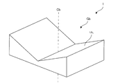
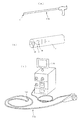
- FIG. 4 is a view showing an example in which the rear deflection member Lbv of the optical system 1 according to the embodiment of the present invention is formed in a wedge prism shape.
- the rear deflection group Gbv includes a rear deflection member Lbv, and the rear deflection member Lbv increases in thickness toward the rear group center axis Cb in the direction toward the outer group with respect to the rear group center axis Cb.
- An element is preferred.
- the rear deflection group Gbv By configuring the rear deflection group Gbv with the rear deflection member Lbv having a refractive action, the rear deflection group Gbv can be formed by polishing or molding, and the productivity can be remarkably improved.
- the rear deflection member Lbv is preferably a wedge prism-shaped optical element.
- both surfaces of the rear deflection member Lbv can be formed as a flat surface, and the productivity can be remarkably improved.
- FIG. 5 is a diagram illustrating an example in which the rear deflection member Lbv of the optical system 1 according to the embodiment of the present invention includes a curved surface.
- the rear deflection group Gbv preferably includes an optical element having a curved surface.
- the post-deflecting member Lbv includes a curved surface, so that the angle of the light beam incident on the image plane can be set more freely.
- the curved surface may be a spherical surface, a toric surface, an anamorphic surface, or a free-form surface.
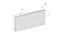
- FIG. 6 is a diagram illustrating an example of a diffraction grating included in the rear deflection group Gbv of the optical system 1 according to an embodiment of the present invention.
- the rear deflection group Gbv may include a diffractive optical element da.
- the diffractive optical element da may have an arbitrary shape.
- the rear deflection group Gbv includes the diffractive optical element da, the occurrence of tilt of the image surface and coma aberration is reduced, the burden of aberration correction in the rear group Gb is reduced, and the optical system is further improved. It becomes possible to reduce the size.
- FIG. 7 is a diagram showing an example in which a diffraction grating is attached to a wedge prism included in the rear deflection group Gbv of the optical system 1 according to an embodiment of the present invention.
- the wedge-shaped prismatic optical element Lbv and the diffractive optical element da may be joined and used. Further, as shown in FIG. 6, the diffractive optical element da may have an arbitrary shape.
- the first front group Gf1 and the second front group Gf2 include a plano-concave negative lens Lf1 11 and Lf2 11 in order from the object side. It is preferable to include the groups Gf1 1 and Gf2 1 and the second groups Gf1 2 and Gf2 2 including the positive cemented lenses SUf1 21 and SUf2 21 .
- the front first group Gf1 1 and Gf2 1 having a strong negative refractive power for taking in a light beam with a wide angle of view and reducing the angle of the off-axis principal ray, and the front first group
- the first lens group G2 includes a front two groups Gf1 2 and Gf2 2 including a positive cemented lens that strongly corrects the lateral chromatic aberration generated in Gf1 1 and Gf2 1 .
- the front one group Gf1 1, Gf2 1 consisting of a plano Lf1 11, Lf2 11, a second group Gf1 2, Gf2 2 before a cemented meniscus lens suf1 21, suf2 21 having a concave surface on the object side, It is preferable to make it the structure containing these.
- the first front group Gf1 and the second front group Gf2 are respectively the front second group Gf1 2 and Gf2 2 on the rear group Gb side of the front second group Gf1 2 and Gf2 2. It is preferable to have front three groups Gf1 3 and Gf2 3 including different positive cemented lenses SUf1 31 and SUf2 31 .
- the luminous flux whose angle of view has been reduced by the front group Gf1 1 and Gf2 1 and the front group Gf1 2 and Gf2 2 of the front group Gf becomes a convergent beam in the front group Gf1 3 and Gf2 3 of the front group Gf. .
- a high load is applied to the front group Gf. Therefore, it is preferable to have the front three groups Gf1 3 and Gf2 3 that correct axial chromatic aberration with at least a cemented lens. Further, it is preferable to have front four groups Gf1 4 and Gf2 4 made of a single positive lens.
- FIG. 8 is a diagram illustrating the position of an image formed only by the front group Gf of the optical system 1 according to an embodiment of the present invention.
- FIG. 9 is a diagram illustrating the focal length f of the optical system 1 according to an embodiment of the present invention.
- the optical system 1 of the present embodiment preferably satisfies the following conditional expression (1).
- FAb is the distance from the final surface of the front group Gf to the imaging position where the light beam exiting the front group Gf forms an image
- f is the focal length of the entire optical system, It is.
- the distance from the final surface of the front group Gf to the imaging position If where the light beam exiting the front group Gf forms an image is FAb.
- the focal length of the entire optical system 1 is assumed to be f.
- the optical system 1 is an eccentric optical system, the eccentricity is removed, a parallel light beam is incident on the optical system 1 from infinity, and the on-axis marginal ray L1 ′ incident on the optical system 1 is emitted after passing through the optical system 1.
- the distance from the virtually bent position A to the image plane I is defined as the focal length f of the optical system 1.
- the optical system 1 of the present embodiment satisfies the following conditional expression (1 ′).
- FIG. 10 is a diagram for explaining the position of the image in a state in which the filter F of the optical system 1 according to the embodiment of the present invention is removed.
- the optical system 1 of the present embodiment preferably satisfies the following conditional expression (2).
- Lb / f ⁇ 5 (2)
- Lb is the distance from the final surface of the rear group Gb to the image plane I
- f is the focal length of the entire optical system 1; It is.
- the optical system 1 of the present embodiment satisfies the following conditional expression (2 ′). Lb / f ⁇ 3 (2 ′)
- optical system 1 of the present embodiment satisfies the following conditional expression (2 ′′). Lb / f ⁇ 2 (2 ′′)
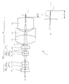
- FIG. 11 is a cross-sectional view taken along the central axis C of the optical system 1 according to another embodiment of the present invention.
- FIG. 12 is a diagram showing the pupil division member 3.
- An optical system 1 includes a shielding member 2 that is disposed in the first front group Gf1 and shields the first light beam L1, and is disposed in the second front group Gf2 and deflects the second light beam L2. It is preferable to include the pupil division member 3.
- the object point distance during stereoscopic observation is 30 cm from infinity, and 0 to 3 m -1 in diopter.
- the object distance is 20 mm to 1 mm, and if it is also diopter, it is 50 to 1000 m ⁇ 1 . For this reason, it is impossible to cope with stereoscopic observation unless the baseline length is changed.
- the optical system 1 of the present embodiment relates to a mechanism for changing the base line length of the three-dimensional magnification optical system in which the object point distance changes greatly as described above.
- stereoscopic imaging is performed with a general optical system 1 having two optical paths.
- a pupil that is a pupil division element that shields the first light beam L1 passing through the first optical path of the two optical paths by the shielding member 2 and divides the pupil into another second optical path.
- the dividing member 3 is inserted and the second light beam L2 is divided into a deflected first light beam L1 ′ and a deflected second light beam L2 ′ by pupil division, and stereoscopic imaging is performed. Therefore, it is possible to obtain a natural three-dimensional effect by switching the base line length corresponding to a significantly different object point distance.
- the pupil dividing member 3 includes a first pupil E1 that forms an image without deflecting a part of the second light beam L2, and a second light beam L2. Of these, it is preferable to form a second pupil E2 that forms an image at a different position on the same plane as the position where the other pupil is imaged by the first pupil E1.
- Pupil dividing member 3 to divide the pupil has a parallel plate portion 3 1 which corresponds to the first pupil E1, a wedge prism portion 3 2 which corresponds to the second pupil E2, the.
- the pupil splitting member 3 has the wedge-shaped prism portion 3 2 having a deflection action, and the second pupil E2 is placed at an adjacent position in the same plane from the imaging position of the deflected first light beam L1 ′ passing through the first pupil E1. It has the action of moving the imaging position of the deflected second light beam L2 ′ that passes therethrough.
- the pupil division member 3 has a positive refractive power, and an imaging position at the time of far-point observation when the pupil division member 3 is not used, It is preferable that the imaging position at the time of near-point observation when the pupil dividing member 3 is used is the same or substantially the same.
- the shielding member 2 and the pupil division member 3 are disposed between the corresponding lenses of the first front group Gf1 and the second front group Gf2. It is preferable.
- the first front 1 group Gf1 1 of plano-concave negative lens Lf1 11 are first cut-out portion 41 1 lacking second front lens group Gf2 side partially cut is formed
- the second The plano-concave negative lens Lf2 11 of the front first group Gf2 1 may be formed with a second notch 41 2 that is partially cut away from the first front group Gf1 side.
- the 1st notch part 41 1 and the 2nd notch part 41 2 are contact
- the distance between the first optical axis of the first front group Gf1 and the second optical axis of the second front group Gf2 is reduced by contacting the first notch part 41 1 and the second notch part 41 2.
- the optical system 1 can be reduced in size.
- the notch is not limited to the first front first group Gf1 1 and the second front first group Gf2 1 , for example, the first front second group Gf1 2, the second front second group Gf2 2 , the first front third group Gf1 3 and the second front third group Gf2 3 may be formed on the lenses of the other first front group Gf1 and the second front group Gf2, and may be brought into contact with each other.
- the light shielding member 5 may be installed between the first cutout portion 41 1 and the second cutout portion 41 2 . By installing the light shielding member 5, it is possible to reduce the possibility that each flare light will be incident between the first front group Gf1 and the second front group Gf2 even if the baseline length is shortened.
- the color misregistration of the image that occurs when deflected by the pupil division member 3 can be corrected electronically. More preferably, shading that occurs when the angle of light incident on the image sensor increases can be corrected electronically.
- Examples 1 to 10 of the optical system 1 according to the present embodiment will be described below.
- the numerical data of Examples 1 to 10 will be described later.
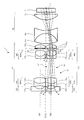
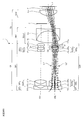
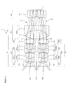
- FIG. 13 is a sectional view taken along the central axis C of the optical system 1 of the first embodiment.
- 14 is a lateral aberration diagram of the optical system 1 of Example 1.
- the angle shown in the center indicates (vertical angle of view), and indicates lateral aberration in the Y direction (meridional direction) and X direction (sagittal direction) at that angle of view.
- a negative angle of view means a clockwise angle facing the positive direction of the X axis. The same applies to the lateral aberration diagrams of Examples 1 to 10.
- the optical system 1 of Embodiment 1 is arranged in parallel with the first front group central axis Cf1 having the first front group central axis Cf1 and the first front group central axis Cf1 in order from the object side to the image side.
- the first front group Gf1 includes a first front first group Gf1 1 having a plano-concave negative lens Lf1 11 facing the object side, a cemented lens SUf1 21 of a biconcave negative lens Lf1 21 and a biconvex positive lens Lf1 22.
- a first front second group Gf1 2 having, a negative meniscus lens Lf1 31 having a convex surface on the object side of the first front third group Gf1 3 having a cemented lens suf1 31 of the biconvex positive lens Lf1 32, the first diaphragm S1
- a first front fourth group Gf1 4 having a positive meniscus lens Lf1 41 having a convex surface facing the image surface side.
- the second front group Gf2 includes a second front first group Gf2 1 having a plano-concave negative lens Lf2 11 facing the object side, a cemented lens SUf2 21 of a biconcave negative lens Lf2 21 and a biconvex positive lens Lf2 22.
- a second front second group Gf2 2 having, a negative meniscus lens Lf2 31 having a convex surface directed toward the object side and a second front third group Gf2 3 having a cemented lens suf2 31 of the biconvex positive lens Lf2 32, a second diaphragm S2
- a second front fourth group Gf2 4 having a positive meniscus lens Lf2 41 with a convex surface facing the image surface side.
- Rear group Gb includes a first group Gb1 after having cemented lens SUB1 1 of the biconvex positive lens Lb 1 a biconcave negative lens Lb 2, the two groups Gb2 after having biconvex positive lens Lb 3, a.
- a filter is placed in front of the image plane I.
- the first light beam L1 incident from the first object surface, not shown in the first front group Gf1 is first pre-1 group Gf1 1 of plano-concave negative lens Lf1 11, first front second group Gf1 2 of cemented lens suf1 21, the The first front group Gf1 3 passes through the cemented lens SUf1 31 , the first aperture stop S1, and the first front fourth group Gf1 4 positive meniscus lens Lf1 41 , and then exits the first front group Gf1. Incident on Gb.
- the second light beam L2 incident on the second front group Gf2 from the second object plane is a plano-concave negative lens Lf2 11 of the second front first group Gf2 1 , a cemented lens SUf2 21 of the second front second group Gf2 2 , 2 After passing through the cemented lens SUf2 31 of the front 3rd group Gf2 3 , the second aperture stop S2, and the positive meniscus lens Lf2 41 of the 2nd front 4th group Gf2 4 , the second front group Gf2 is emitted, and then the rear group Incident on Gb.
- the first light beam L1 and the second light beam L2 incident on the rear group Gb pass through the cemented lens SUb1 1 of the rear first group Gb1, the biconvex positive lens Lb 3 of the rear second group Gb2, and the filter F, respectively. Is incident on.
- FIG. 15 is a cross-sectional view taken along the central axis C of the optical system 1 of the second embodiment.
- FIG. 16 is a lateral aberration diagram of the optical system 1 of Example 2.
- the optical system 1 of Example 2 is arranged in parallel with the first front group center axis Cf1 having the first front group center axis Cf1 and the first front group center axis Cf1 in order from the object side to the image side.
- the first front group Gf1 includes a first front first group Gf1 1 having a plano-concave negative lens Lf1 11 facing the object side, a cemented lens SUf1 21 of a biconcave negative lens Lf1 21 and a biconvex positive lens Lf1 22.
- a first front second group Gf1 2 having, a negative meniscus lens Lf1 31 having a convex surface on the object side of the first front third group Gf1 3 having a cemented lens suf1 31 of the biconvex positive lens Lf1 32, the first diaphragm S1
- a first front fourth group Gf1 4 having a positive meniscus lens Lf1 41 having a convex surface facing the image surface side.
- the second front group Gf2 includes a second front first group Gf2 1 having a plano-concave negative lens Lf2 11 facing the object side, a cemented lens SUf2 21 of a biconcave negative lens Lf2 21 and a biconvex positive lens Lf2 22.
- a second front second group Gf2 2 having, a negative meniscus lens Lf2 31 having a convex surface directed toward the object side and a second front third group Gf2 3 having a cemented lens suf2 31 of the biconvex positive lens Lf2 32, a second diaphragm S2
- a second front fourth group Gf2 4 having a positive meniscus lens Lf2 41 with a convex surface facing the image surface side.
- Rear group Gb includes a first group Gb1 after having cemented lens SUB1 1 of the biconvex positive lens Lb 1 a biconcave negative lens Lb 2, the two groups Gb2 after having biconvex positive lens Lb 3, a.
- a filter is placed in front of the image plane I.
- the plano-concave negative lens Lf1 11 of the first front first group Gf1 1 is formed with a first front first group first cutout portion 4 11 that is partially cut away from the second front group Gf2 side, and the second front first group Gf2 1 of plano-concave negative lens Lf2 11, the second front group 1 second notch 4 12 lacking the first front group Gf1 side partially cut is formed.
- the first light beam L1 incident from the first object surface, not shown in the first front group Gf1 is first pre-1 group Gf1 1 of plano-concave negative lens Lf1 11, first front second group Gf1 2 of cemented lens suf1 21, the The first front group Gf1 3 passes through the cemented lens SUf1 31 , the first aperture stop S1, and the first front fourth group Gf1 4 positive meniscus lens Lf1 41 , and then exits the first front group Gf1. Incident on Gb.
- the second light beam L2 incident on the second front group Gf2 from the second object plane is a plano-concave negative lens Lf2 11 of the second front first group Gf2 1 , a cemented lens SUf2 21 of the second front second group Gf2 2 , 2 After passing through the cemented lens SUf2 31 of the front 3rd group Gf2 3 , the second aperture stop S2, and the positive meniscus lens Lf2 41 of the 2nd front 4th group Gf2 4 , the second front group Gf2 is emitted, and then the rear group Incident on Gb.
- the first light beam L1 and the second light beam L2 incident on the rear group Gb pass through the cemented lens SUb1 1 of the rear first group Gb1, the biconvex positive lens Lb 3 of the rear second group Gb2, and the filter F, respectively. Is incident on.
- FIG. 17 is a cross-sectional view taken along the central axis C of the optical system 1 of the third embodiment.
- FIG. 18 is a lateral aberration diagram of the optical system 1 of Example 3.
- the optical system 1 of Example 3 is arranged in parallel with the first front group Gf1 having the first front group center axis Cf1 and the first front group center axis Cf1 in order from the object side to the image side.
- the first front group Gf1 includes a first front first group Gf1 1 having a plano-concave negative lens Lf1 11 facing the object side, a cemented lens SUf1 21 of a biconcave negative lens Lf1 21 and a biconvex positive lens Lf1 22.
- a first front second group Gf1 2 having, a first aperture S1, a negative meniscus lens Lf1 31 having a convex surface on the object side of the first front third group Gf1 3 having a cemented lens suf1 31 of the biconvex positive lens Lf1 32 are preferably provided.
- the second front group Gf2 includes a second front first group Gf2 1 having a plano-concave negative lens Lf2 11 facing the object side, a cemented lens SUf2 21 of a biconcave negative lens Lf2 21 and a biconvex positive lens Lf2 22.
- a second front second group Gf2 2 having, a second diaphragm S2, a negative meniscus lens Lf2 31 having a convex surface directed toward the object side and a second front third group Gf2 3 having a cemented lens suf2 31 of the biconvex positive lens Lf2 32 are preferably provided.
- Rear group Gb includes a first group Gb1 after having cemented lens SUB1 1 of the biconvex positive lens Lb 1 a biconcave negative lens Lb 2, the two groups Gb2 after having biconvex positive lens Lb 3, a.
- a filter is placed in front of the image plane I.
- the plano-concave negative lens Lf1 11 of the first front first group Gf1 1 is formed with a first front first group first cutout portion 4 11 that is partially cut away from the second front group Gf2 side, and the second front first group Gf2 1 of plano-concave negative lens Lf2 11, the second front group 1 second notch 4 12 lacking the first front group Gf1 side partially cut is formed.
- a light shielding member may be provided between the notch portions where the first front group Gf1 and the second front group Gf2 are in contact.
- the first light beam L1 incident from the first object surface, not shown in the first front group Gf1 is first pre-1 group Gf1 1 of plano-concave negative lens Lf1 11, first front second group Gf1 2 of cemented lens suf1 21, the 1 diaphragm S1 and passes through the cemented lens suf1 31 in the first front third group Gf1 3, a first front unit Gf1 injection, then enters the rear group Gb.
- the second light beam L2 incident on the second front group Gf2 from the second object plane is a plano-concave negative lens Lf2 11 of the second front first group Gf2 1 , a cemented lens SUf2 21 of the second front second group Gf2 2 , After passing through the second stop S2 and the cemented lens SUf2 31 of the second front third group Gf2 3 , the second front group Gf2 exits and then enters the rear group Gb.
- the first light beam L1 and the second light beam L2 incident on the rear group Gb pass through the cemented lens SUb1 1 of the rear first group Gb1, the biconvex positive lens Lb 3 of the rear second group Gb2, and the filter F, respectively. Is incident on.
- FIG. 19 is a cross-sectional view taken along the central axis C of the optical system 1 of the fourth embodiment.
- FIG. 20 is a lateral aberration diagram of the optical system 1 according to Example 4.
- the optical system 1 of Example 4 is arranged in parallel with the first front group Gf1 having the first front group center axis Cf1 and the first front group center axis Cf1 in order from the object side to the image side.
- the first front group Gf1 includes a first front first group Gf1 1 having a plano-concave negative lens Lf1 11 facing the object side, a cemented lens SUf1 21 of a biconcave negative lens Lf1 21 and a biconvex positive lens Lf1 22.
- a first front second group Gf1 2 having, a first aperture S1, a negative meniscus lens Lf1 31 having a convex surface on the object side of the first front third group Gf1 3 having a cemented lens suf1 31 of the biconvex positive lens Lf1 32 are preferably provided.
- the second front group Gf2 includes a second front first group Gf2 1 having a plano-concave negative lens Lf2 11 facing the object side, a cemented lens SUf2 21 of a biconcave negative lens Lf2 21 and a biconvex positive lens Lf2 22.
- a second front second group Gf2 2 having, a second diaphragm S2, a negative meniscus lens Lf2 31 having a convex surface directed toward the object side and a second front third group Gf2 3 having a cemented lens suf2 31 of the biconvex positive lens Lf2 32 are preferably provided.
- Rear group Gb includes a first group Gb1 after having cemented lens SUB1 1 of the biconvex positive lens Lb 1 a biconcave negative lens Lb 2, the two groups Gb2 after having biconvex positive lens Lb 3, a.
- a filter is placed in front of the image plane I.
- the plano-concave negative lens Lf1 11 of the first front first group Gf1 1 is formed with a first front first group first cutout portion 4 11 that is partially cut away from the second front group Gf2 side, and the second front first group Gf2 1 of plano-concave negative lens Lf2 11, the second front group 1 second notch 4 12 lacking the first front group Gf1 side partially cut is formed.
- the negative meniscus lens Lf1 31 having a convex surface facing the object side of the first front third group Gf1 3 and the cemented lens SUf1 31 of the biconvex positive lens Lf1 32 are partially cut away on the second front group Gf2 side.
- a cemented lens SUf2 31 of a negative meniscus lens Lf2 31 and a biconvex positive lens Lf2 32 having a front third group first cutout portion 4 31 and having a convex surface facing the object side of the second front third group Gf2 3 second front third group second cut-out portion 4 32 are formed devoid of front group Gf1 side partially cut.
- the first light beam L1 incident from the first object surface, not shown in the first front group Gf1 is first pre-1 group Gf1 1 of plano-concave negative lens Lf1 11, first front second group Gf1 2 of cemented lens suf1 21, the 1 diaphragm S1 and passes through the cemented lens suf1 31 in the first front third group Gf1 3, a first front unit Gf1 injection, then enters the rear group Gb.
- the second light beam L2 incident on the second front group Gf2 from the second object plane is a plano-concave negative lens Lf2 11 of the second front first group Gf2 1 , a cemented lens SUf2 21 of the second front second group Gf2 2 , After passing through the second stop S2 and the cemented lens SUf2 31 of the second front third group Gf2 3 , the second front group Gf2 exits and then enters the rear group Gb.
- the first light beam L1 and the second light beam L2 incident on the rear group Gb pass through the cemented lens SUb1 1 of the rear first group Gb1, the biconvex positive lens Lb 3 of the rear second group Gb2, and the filter F, respectively. Is incident on.
- FIG. 21 is a cross-sectional view taken along the central axis C of the optical system 1 of the fifth embodiment.
- FIG. 22 is a lateral aberration diagram of the optical system 1 according to Example 5.
- the optical system 1 of Example 5 is arranged in parallel with the first front group center axis Cf1 and the first front group center axis Cf1 having the first front group center axis Cf1 in order from the object side to the image side.
- the first front group Gf1 includes a first front first group Gf1 1 having a plano-concave negative lens Lf1 11 facing the object side, a cemented lens SUf1 21 of a biconcave negative lens Lf1 21 and a biconvex positive lens Lf1 22.
- a first front second group Gf1 2 having, a first aperture S1, a negative meniscus lens Lf1 31 having a convex surface on the object side of the first front third group Gf1 3 having a cemented lens suf1 31 of the biconvex positive lens Lf1 32 are preferably provided.
- the second front group Gf2 includes a second front first group Gf2 1 having a plano-concave negative lens Lf2 11 facing the object side, a cemented lens SUf2 21 of a biconcave negative lens Lf2 21 and a biconvex positive lens Lf2 22.
- a second front second group Gf2 2 having, a second diaphragm S2, a negative meniscus lens Lf2 31 having a convex surface directed toward the object side and a second front third group Gf2 3 having a cemented lens suf2 31 of the biconvex positive lens Lf2 32 are preferably provided.
- the rear group Gb includes a rear first group Gb1 having a positive meniscus lens Lb 1 with a convex surface facing the image surface side, and a rear second group Gb2 having a cemented lens SUb2 1 of a biconvex positive lens Lb 2 and a biconcave negative lens Lb 3. And comprising.
- a filter is placed in front of the image plane I.
- the plano-concave negative lens Lf1 11 of the first front first group Gf1 1 is formed with a first front first group first cutout portion 4 11 that is partially cut away from the second front group Gf2 side, and the second front first group Gf2 1 of plano-concave negative lens Lf2 11, the second front group 1 second notch 4 12 lacking the first front group Gf1 side partially cut is formed.
- a light shielding member may be installed between the notch portions where the first front group Gf1 and the third front group Gf3 abut.
- the first light beam L1 incident from the first object surface, not shown in the first front group Gf1 is first pre-1 group Gf1 1 of plano-concave negative lens Lf1 11, first front second group Gf1 2 of cemented lens suf1 21, the 1 diaphragm S1 and passes through the cemented lens suf1 31 in the first front third group Gf1 3, a first front unit Gf1 injection, then enters the rear group Gb.
- the second light beam L2 incident on the second front group Gf2 from the second object plane is a plano-concave negative lens Lf2 11 of the second front first group Gf2 1 , a cemented lens SUf2 21 of the second front second group Gf2 2 , After passing through the second stop S2 and the cemented lens SUf2 31 of the second front third group Gf2 3 , the second front group Gf2 exits and then enters the rear group Gb.
- the first light beam L1 and the second light beam L2 incident on the rear group Gb pass through the positive meniscus lens Lb 1 of the rear first group Gb1, the cemented lens SUb2 1 of the rear second group Gb2, and the filter F, respectively. Incident.
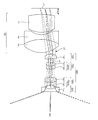
- FIG. 23 is a cross-sectional view taken along the central axis C of the optical system 1 during far-point observation in Example 6.
- FIG. 24 is a cross-sectional view along the central axis C of the optical system 1 during near-point observation in Example 6.
- FIG. 25 is a lateral aberration diagram of the optical system 1 during the far-point observation in Example 6.
- FIG. 26 is a lateral aberration diagram for the deflected first light beam L1 'that passes through the first pupil E1 of the optical system 1 during the near-point observation according to the sixth embodiment.
- FIG. 27 is a lateral aberration diagram for the deflected second light beam L2 'that passes through the second pupil E2 of the optical system 1 during the near-point observation in Example 6.
- the optical system 1 of Example 6 is arranged in parallel with the first front group Gf1 having the first front group center axis Cf1 and the first front group center axis Cf1 in order from the object side to the image side.
- the first front group Gf1 includes a first front first group Gf1 1 having a plano-concave negative lens Lf1 11 facing the object side, a cemented lens SUf1 21 of a biconcave negative lens Lf1 21 and a biconvex positive lens Lf1 22.
- a first front second group Gf1 2 having, a negative meniscus lens Lf1 31 having a convex surface on the object side of the first front third group Gf1 3 having a cemented lens suf1 31 of the biconvex positive lens Lf1 32, the first diaphragm S1
- a first front fourth group Gf1 4 having a negative meniscus lens Lf1 41 having a convex surface directed toward the image surface side.
- the second front group Gf2 includes a second front first group Gf2 1 having a plano-concave negative lens Lf2 11 facing the object side, a cemented lens SUf2 21 of a biconcave negative lens Lf2 21 and a biconvex positive lens Lf2 22.
- a second front second group Gf2 2 having, a negative meniscus lens Lf2 31 having a convex surface directed toward the object side and a second front third group Gf2 3 having a cemented lens suf2 31 of the biconvex positive lens Lf2 32, a second diaphragm S2
- a second front fourth group Gf2 4 having a negative meniscus lens Lf2 41 having a convex surface directed toward the image surface side.
- Rear group Gb includes a biconvex positive lens Lb 1 and 1 group Gb1 after having cemented lens SUB1 1 of the biconcave negative lens Lb 2, the two groups Gb2 after having a positive meniscus lens Lb 3 having a convex surface facing the object side .
- a filter is placed in front of the image plane I.
- the first light beam L1 incident from the first object surface, not shown in the first front group Gf1 is first pre-1 group Gf1 1 of plano-concave negative lens Lf1 11, first front second group Gf1 2 of cemented lens suf1 21, the The first front group Gf1 3 passes through the cemented lens SUf1 31 , the first aperture stop S1, and the first front fourth group Gf1 4 negative meniscus lens Lf1 41 , and then the first front group Gf1 is emitted, and then the rear group Incident on Gb.
- the second light beam L2 incident on the second front group Gf2 from the second object plane is a plano-concave negative lens Lf2 11 of the second front first group Gf2 1 , a cemented lens SUf2 21 of the second front second group Gf2 2 , 2 After passing through the cemented lens SUf2 31 of the front third group Gf2 3 , the second diaphragm S2, and the negative meniscus lens Lf2 41 of the second front fourth group Gf2 4 , the second front group Gf2 is emitted, and then the rear group Incident on Gb.
- the first light beam L1 and the second light beam L2 incident on the rear group Gb pass through the cemented lens SUb1 1 of the rear first group Gb1, the positive meniscus lens Lb 3 of the rear second group Gb2, and the filter F, respectively. Incident.
- the optical system 1 of Example 6 can perform near-point observation by installing a shielding member 2 and a pupil dividing member 3.
- the shielding member 2 shields the first light beam L1 shown in FIG. In the example shown in FIG. 24, the shielding member 2 is installed between the rear first group Gb1 and the rear second group Gb2 of the rear group Gb, but the shielding member 2 is installed between any of the lenses of the first front group Gf1. May be.
- the shielding member 2 may be installed between the front group Gf and the rear group Gb.
- the pupil dividing member 3 forms an image with the first pupil E1 that forms an image without deflecting a part of the second light beam L2 shown in FIG. 23, and the other portion of the second light beam L2 with the first pupil. And a second pupil E2 that forms an image at a different position on the same plane as the position to be formed.
- Pupil dividing member 3 to divide the pupil has a parallel plate portion 3 1 which corresponds to the first pupil E1, a wedge prism portion 3 2 which corresponds to the second pupil E2, the.
- the pupil splitting member 3 has the wedge-shaped prism portion 3 2 having a deflection action, and the second pupil E2 is placed at an adjacent position in the same plane from the imaging position of the deflected first light beam L1 ′ passing through the first pupil E1. It has the action of moving the imaging position of the deflected second light beam L2 ′ that passes therethrough.
- FIG. 28 is a cross-sectional view along the central axis C of the optical system 1 during far-point observation in Example 7.
- FIG. 29 is a cross-sectional view along the central axis C of the optical system 1 during near-point observation in Example 7.
- FIG. 30 is a lateral aberration diagram of the optical system 1 during the far-point observation in Example 7.
- FIG. 31 is a lateral aberration diagram for the deflected first light beam L1 'that passes through the first pupil E1 of the optical system 1 during the near-point observation in Example 7.
- FIG. 32 is a transverse aberration diagram for the deflected second light beam L2 'that passes through the second pupil E2 of the optical system 1 during the near-point observation according to the seventh embodiment.
- the optical system 1 of Example 7 is arranged in parallel with the first front group Gf1 having the first front group center axis Cf1 and the first front group center axis Cf1 in order from the object side to the image side.
- the first front group Gf1 includes a first front first group Gf1 1 having a plano-concave negative lens Lf1 11 facing the object side, a cemented lens SUf1 21 of a biconcave negative lens Lf1 21 and a biconvex positive lens Lf1 22.
- a first front second group Gf1 2 having, a negative meniscus lens Lf1 31 having a convex surface on the object side of the first front third group Gf1 3 having a cemented lens suf1 31 of the biconvex positive lens Lf1 32, the first diaphragm S1
- a first front fourth group Gf1 4 having a negative meniscus lens Lf1 41 having a convex surface directed toward the image surface side.
- the second front group Gf2 includes a second front first group Gf2 1 having a plano-concave negative lens Lf2 11 facing the object side, a cemented lens SUf2 21 of a biconcave negative lens Lf2 21 and a biconvex positive lens Lf2 22.
- a second front second group Gf2 2 having, a negative meniscus lens Lf2 31 having a convex surface directed toward the object side and a second front third group Gf2 3 having a cemented lens suf2 31 of the biconvex positive lens Lf2 32, a second diaphragm S2
- a second front fourth group Gf2 4 having a negative meniscus lens Lf2 41 having a convex surface directed toward the image surface side.
- Rear group Gb includes a first group Gb1 after having cemented lens SUB1 1 of the biconvex positive lens Lb 1 a biconcave negative lens Lb 2, the two groups Gb2 after having biconvex positive lens Lb 3, a.
- a filter is placed in front of the image plane I.
- the first light beam L1 incident from the first object surface, not shown in the first front group Gf1 is first pre-1 group Gf1 1 of plano-concave negative lens Lf1 11, first front second group Gf1 2 of cemented lens suf1 21, the The first front group Gf1 3 passes through the cemented lens SUf1 31 , the first aperture stop S1, and the first front fourth group Gf1 4 negative meniscus lens Lf1 41 , and then the first front group Gf1 is emitted, and then the rear group Incident on Gb.
- the second light beam L2 incident on the second front group Gf2 from the second object plane is a plano-concave negative lens Lf2 11 of the second front first group Gf2 1 , a cemented lens SUf2 21 of the second front second group Gf2 2 , 2 After passing through the cemented lens SUf2 31 of the front third group Gf2 3 , the second diaphragm S2, and the negative meniscus lens Lf2 41 of the second front fourth group Gf2 4 , the second front group Gf2 is emitted, and then the rear group Incident on Gb.
- the first light beam L1 and the second light beam L2 incident on the rear group Gb pass through the cemented lens SUb1 1 of the rear first group Gb1, the biconvex positive lens Lb 3 of the rear second group Gb2, and the filter F, respectively. Is incident on.
- the optical system 1 of Example 7 can perform near-point observation by installing a shielding member 2 and a pupil dividing member 3.
- the shielding member 2 shields the first light beam L1 shown in FIG. In the example shown in FIG. 29, the shielding member 2 is installed in the vicinity of the first diaphragm S1 between the first front third group Gf1 3 and the first front fourth group Gf1 4 .
- the pupil splitting member 3 forms an image with the first pupil E1 that forms an image without deflecting a part of the second light beam L2 shown in FIG. 28 and the other portion of the second light beam L2 with the first pupil. And a second pupil E2 that forms an image at a different position on the same plane as the position to be formed.
- Pupil dividing member 3 to divide the pupil has a parallel plate portion 3 1 which corresponds to the first pupil E1, a wedge prism portion 3 2 which corresponds to the second pupil E2, the.
- the pupil splitting member 3 has the wedge-shaped prism portion 3 2 having a deflection action, and the second pupil E2 is placed at an adjacent position in the same plane from the imaging position of the deflected first light beam L1 ′ passing through the first pupil E1. It has the action of moving the imaging position of the deflected second light beam L2 ′ that passes therethrough.
- the light shielding member 2 is disposed in the vicinity of the first diaphragm S1 between the first front third group Gf1 3 and the first front fourth group Gf1 4 , and the pupil division member 3 is disposed on the second front side. It is arranged in the vicinity of the second diaphragm S2 between the third group Gf2 3 and the second front fourth group Gf2 4 . That is, the light shielding member 2 and the pupil division member 3 are disposed between the corresponding lenses of the first front group Gf1 and the second front group Gf2.
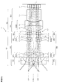
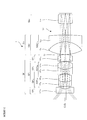
- FIG. 33 is a cross-sectional view including the first front group center axis Cf1 and the second front group center axis Cf2 of the optical system 1 according to the eighth embodiment.
- FIG. 34 is a diagram viewed from a direction orthogonal to FIG. 35 and 36 are lateral aberration diagrams of the optical system 1 of Example 8.
- FIG. 34 is a diagram viewed from a direction orthogonal to FIG. 35 and 36 are lateral aberration diagrams of the optical system 1 of Example 8.
- the optical system 1 of Example 8 is arranged in parallel with the first front group center axis Cf1 having the first front group center axis Cf1 and the first front group center axis Cf1 in order from the object side to the image side.
- a rear deflection group Gbv arranged.
- the first front group Gf1 includes a first front first group Gf1 1 having a plano-concave negative lens Lf1 11 facing the object side, a cemented lens SUf1 21 of a biconcave negative lens Lf1 21 and a biconvex positive lens Lf1 22.
- a first front second group Gf1 2 having, a negative meniscus lens Lf1 31 having a convex surface on the object side of the first front third group Gf1 3 having a cemented lens suf1 31 of the biconvex positive lens Lf1 32, the first diaphragm S1 are preferably provided.
- the image side surface of the plano-concave negative lens Lf1 11 is an aspherical surface.
- the second front group Gf2 includes a second front first group Gf2 1 having a plano-concave negative lens Lf2 11 facing the object side, a cemented lens SUf2 21 of a biconcave negative lens Lf2 21 and a biconvex positive lens Lf2 22.
- a second front second group Gf2 2 having, a negative meniscus lens Lf2 31 having a convex surface directed toward the object side and a second front third group Gf2 3 having a cemented lens suf2 31 of the biconvex positive lens Lf2 32, a second diaphragm S2 are preferably provided.
- the image side surface of the plano-concave negative lens Lf2 11 is aspheric.
- the rear group Gb preferably includes a rear first group Gb1 having a biconvex positive lens Lb 1 and a biconcave negative lens Lb 2 .
- the rear deflection group Gbv is disposed between the rear group Gb and the image plane I and includes a rear deflection member Lbv that deflects the first light beam L1 and the second light beam L2.
- the rear deflection member Lbv relaxes the convergence of the first light beam L1 and the second light beam L2 after exiting the rear group Gb, and the absolute values of the incident angles of the first light beam L1 and the second light beam L2 on the image plane I are reduced.
- Deflection is preferably performed so as to be smaller than the absolute value of the incident angle to the rear deflection group Gbv.
- the first light beam L1 incident on the first front group Gf1 from the first object surface is a plano-concave negative lens Lf1 11 of the first front first group Gf1 1 , a cemented lens SUf1 21 of the first front second group Gf1 2 , the first front
- the light passes through the cemented lens SUf1 31 of the third group Gf1 3 and the first diaphragm S1, exits the first front group Gf1, and then enters the rear group Gb.
- the second light beam L2 incident on the second front group Gf2 from the second object plane includes a plano-concave negative lens Lf2 11 of the second front first group Gf2 1 , a cemented lens SUf2 21 of the second front second group Gf2 2, a second front
- the light passes through the cemented lens SUf2 31 of the third group Gf2 3 and the second diaphragm S2, exits the second front group Gf2, and then enters the rear group Gb.
- the first light beam L1 and the second light beam L2 incident on the rear group Gb pass through the biconvex positive lens Lb 1 , the biconcave negative lens Lb 2 of the rear first group Gb1, and the rear deflection member Lbv of the rear deflection group Gbv, respectively. Is incident on the image plane.
- the rear deflection group Gbv includes a rear deflection member Lbv, and the rear deflection member Lbv moves rearward toward the outer peripheral side with respect to the rear group central axis Cb.
- This is an optical element having a large thickness in the group center axis Cb direction.
- the rear deflection group Gbv By configuring the rear deflection group Gbv with the rear deflection member Lbv having a refractive action, the rear deflection group Gbv can be formed by polishing or molding, and the productivity can be remarkably improved.
- the rear deflection member Lbv is an optical element having a wedge prism shape.
- both surfaces of the rear deflection member Lbv can be formed as a flat surface, and the productivity can be remarkably improved.
- FIG. 37 is a cross-sectional view including the first front group central axis Cf1 and the second front group central axis Cf2 of the optical system 1 of Example 9.
- FIG. 38 is a view as seen from the direction orthogonal to FIG. 39 and 40 are lateral aberration diagrams of the optical system 1 according to Example 9.
- FIG. 38 is a cross-sectional view including the first front group central axis Cf1 and the second front group central axis Cf2 of the optical system 1 of Example 9.
- FIG. 38 is a view as seen from the direction orthogonal to FIG. 39 and 40 are lateral aberration diagrams of the optical system 1 according to Example 9.
- the optical system 1 of Example 9 is arranged in parallel with the first front group center axis Cf1 having the first front group center axis Cf1 and the first front group center axis Cf1 in order from the object side to the image side.
- a rear deflection group Gbv arranged.
- the first front group Gf1 includes a first front first group Gf1 1 having a plano-concave negative lens Lf1 11 facing the object side, a cemented lens SUf1 21 of a biconcave negative lens Lf1 21 and a biconvex positive lens Lf1 22.
- the image side surface of the plano-concave negative lens Lf1 11 is an aspherical surface.
- the second front group Gf2 includes a second front first group Gf2 1 having a plano-concave negative lens Lf2 11 facing the object side, a cemented lens SUf2 21 of a biconcave negative lens Lf2 21 and a biconvex positive lens Lf2 22.
- the image side surface of the plano-concave negative lens Lf2 11 is aspheric.
- Rear group Gb is preferably provided with a first group Gb1 after having cemented lens SUB1 11 of the biconvex positive lens Lb 1 a biconcave negative lens Lb 2.
- the rear deflection group Gbv is disposed between the rear group Gb and the image plane I and includes a rear deflection member Lbv that deflects the first light beam L1 and the second light beam L2.
- the rear deflection member Lbv relaxes the convergence of the first light beam L1 and the second light beam L2 after exiting the rear group Gb, and the absolute values of the incident angles of the first light beam L1 and the second light beam L2 on the image plane I are reduced.
- Deflection is preferably performed so as to be smaller than the absolute value of the incident angle to the rear deflection group Gbv.
- the first light beam L1 incident on the first front group Gf1 from the first object surface is a plano-concave negative lens Lf1 11 of the first front first group Gf1 1 , a cemented lens SUf1 21 of the first front second group Gf1 2 , the first front
- the light passes through the cemented lens SUf1 31 of the third group Gf1 3 and the first diaphragm S1, exits the first front group Gf1, and then enters the rear group Gb.
- the second light beam L2 incident on the second front group Gf2 from the second object plane includes a plano-concave negative lens Lf2 11 of the second front first group Gf2 1 , a cemented lens SUf2 21 of the second front second group Gf2 2, a second front
- the light passes through the cemented lens SUf2 31 of the third group Gf2 3 and the second diaphragm S2, exits the second front group Gf2, and then enters the rear group Gb.
- the first light beam L1 and the second light beam L2 incident on the rear group Gb pass through the cemented lens SUb1 11 of the rear first group Gb1 and the rear deflection member Lbv of the rear deflection group Gbv, respectively, and enter the image plane.
- the rear deflection group Gbv includes a rear deflection member Lbv, and the rear deflection member Lbv moves rearward toward the outer peripheral side with respect to the rear group central axis Cb.
- This is an optical element having a large thickness in the group center axis Cb direction.
- the rear deflection group Gbv By configuring the rear deflection group Gbv with the rear deflection member Lbv having a refractive action, the rear deflection group Gbv can be formed by polishing or molding, and the productivity can be remarkably improved.
- the rear deflection member Lbv is a wedge prism-shaped optical element.
- both surfaces of the rear deflection member Lbv can be formed as a flat surface, and the productivity can be remarkably improved.
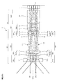
- FIG. 41 is a cross-sectional view including the first front group central axis Cf1 and the second front group central axis Cf2 of the optical system 1 of Example 10.
- FIG. 42 is a diagram viewed from a direction orthogonal to FIG. 43 and 44 are lateral aberration diagrams of the optical system 1 of Example 10.
- the optical system 1 of Example 10 is in parallel with the first front group Gf1 having the first front group center axis Cf1 and the first front group center axis Cf1 in order from the object side to the image side.
- a rear deflection group Gbv arranged.
- the first front group Gf1 includes a first front first group Gf1 1 having a plano-concave negative lens Lf1 11 facing the object side, a cemented lens SUf1 21 of a biconcave negative lens Lf1 21 and a biconvex positive lens Lf1 22.
- the image side surface of the plano-concave negative lens Lf1 11 is an aspherical surface.
- the second front group Gf2 includes a second front first group Gf2 1 having a plano-concave negative lens Lf2 11 facing the object side, a cemented lens SUf2 21 of a biconcave negative lens Lf2 21 and a biconvex positive lens Lf2 22.
- the image side surface of the plano-concave negative lens Lf2 11 is aspheric.
- Rear group Gb is preferably provided with a first group Gb1 after having cemented lens SUB1 11 of the negative meniscus lens Lb 2 having a convex surface directed toward the biconvex positive lens Lb 1 and the image plane I side.
- the rear deflection group Gbv is disposed between the rear group Gb and the image plane I, and has a rear deflection member Lbv that deflects the first light beam L1 and the second light beam L2.
- the rear deflection member Lbv relaxes the convergence of the first light beam L1 and the second light beam L2 after exiting the rear group Gb, and the absolute values of the incident angles of the first light beam L1 and the second light beam L2 on the image plane I are reduced.
- Deflection is preferably performed so as to be smaller than the absolute value of the incident angle to the rear deflection group Gbv.
- the first light beam L1 incident on the first front group Gf1 from the first object surface is a plano-concave negative lens Lf1 11 of the first front first group Gf1 1 , a cemented lens SUf1 21 of the first front second group Gf1 2 , the first front
- the light passes through the cemented lens SUf1 31 of the third group Gf1 3 and the first diaphragm S1, exits the first front group Gf1, and then enters the rear group Gb.
- the second light beam L2 incident on the second front group Gf2 from the second object plane includes a plano-concave negative lens Lf2 11 of the second front first group Gf2 1 , a cemented lens SUf2 21 of the second front second group Gf2 2, a second front
- the light passes through the cemented lens SUf2 31 of the third group Gf2 3 and the second diaphragm S2, exits the second front group Gf2, and then enters the rear group Gb.
- the first light beam L1 and the second light beam L2 incident on the rear group Gb pass through the cemented lens SUb1 11 of the rear first group Gb1 and the rear deflection member Lbv of the rear deflection group Gbv, respectively, and enter the image plane.
- the rear deflection group Gbv includes an optical element having a curved surface.
- the post-deflecting member Lbv includes a curved surface, so that the angle of the light beam incident on the image plane can be set more freely.
- the curved surface may be a spherical surface, a toric surface, an anamorphic surface, or a free-form surface.
- the rear deflection member Lbv can be arranged in any embodiment.
- the coordinate system is defined for each surface.
- the direction from the origin O of the coordinate system in which the surface is defined toward the image plane at each central axis is defined as the positive Z-axis direction.
- the direction from the second front group center axis Cf2 to the first front group center axis Cf1 on the same plane is defined as the X-axis positive direction.
- the positive Y-axis direction is defined by a right-handed coordinate system.
- optical action surfaces constituting the optical system of each embodiment, when a specific surface and a subsequent surface constitute a coaxial optical system, a surface interval is given.
- curvature radius of the surface, the medium Refractive index and Abbe number are given according to conventional methods.
- the amount of eccentricity from the origin O of the coordinate system in which the surface is defined (X-axis direction, Y-axis direction, and Z-axis direction are X, Y, Z, respectively) and the coordinate system defined by the origin O
- the tilt angles ( ⁇ , ⁇ , ⁇ (°), respectively) of the coordinate system defining each surface centered on the X axis, the Y axis, and the Z axis are given.
- positive ⁇ and ⁇ mean counterclockwise rotation with respect to the positive direction of each axis
- positive ⁇ means clockwise rotation with respect to the positive direction of the Z axis.
- the ⁇ , ⁇ , and ⁇ rotations of the central axis of the surface are performed by rotating the coordinate system defining each surface counterclockwise around the X axis of the coordinate system defined at the origin of the optical system. Then rotate it around the Y axis of the new rotated coordinate system by ⁇ and then rotate it around the Z axis of another rotated new coordinate system by ⁇ . It is.
- Refractive index and Abbe number are shown for d-line (wavelength 587.56 nm).
- the unit of length is mm.
- the eccentricity of each surface is expressed by the amount of eccentricity from the reference surface. “ ⁇ ” described in the radius of curvature indicates infinite.
- the aspheric data used in the present embodiment includes data relating to the aspherical lens surface in the surface data.
- the aspherical shape is expressed by the following formula (a), where z is an optical axis with the light traveling direction being positive, and y is a direction orthogonal to the optical axis.
- z (y 2 / r) / [1+ ⁇ 1 ⁇ (1 + K) ⁇ (y / r) 2 ⁇ 1/2 ] + A4y 4 + A6y 6 + A8y 8 + A10y 10 ... (a)
- r is a paraxial radius of curvature
- K is a conical coefficient
- A4, A6, and A8 are fourth-order, sixth-order, and eighth-order aspheric coefficients, respectively.
- the symbol “e” indicates that the subsequent numerical value is a power exponent with 10 as the base. For example, “1.0e-5” means “1.0 ⁇ 10 ⁇ 5 ”.
- the shape of the free-form surface FFS used in this embodiment is defined by the following equation (b).
- Z in the definition formula is the Z axis of the free-form surface FFS.
- the coefficient term for which no data is described is zero.
- the definition formula (b) is shown as an example as described above, and the free-form surface of the present invention uses a rotationally asymmetric surface to correct rotationally asymmetric aberration caused by decentration.
- the feature is that the manufacturability is also improved, and it goes without saying that the same effect can be obtained for any other defining formula.
- Example 8 Surface number Curvature radius Surface spacing Eccentricity Refractive index Abbe number Object surface ⁇ 20.000 1 ⁇ 0.500 1.8830 40.7 2 Aspherical surface [1] 1.439 3 -39.792 0.500 1.8830 40.7 4 1.534 0.900 1.7847 25.7 5 -4.963 0.100 6 4.316 0.500 1.9229 18.9 7 1.596 0.900 1.5831 59.4 8 -1.806 0.050 9 Aperture surface 0.000 10 Reference surface 0.000 Eccentricity (1) 11 2.834 1.200 1.5831 59.4 12 -46.290 0.878 13 -40.929 0.600 1.9229 18.9 14 5.915 0.383 15 ⁇ 1.100 Eccentricity (2) 1.5163 64.1 16 ⁇ 0.150 Eccentricity (3) Image plane ⁇ Eccentricity (3) Aspherical [1] Curvature radius 0.717 k -2.2311e-001 Eccentric [1] X 1.000 Y 0.000 Z 0.000 ⁇ 0.000 ⁇ 0.000 ⁇ 0.000 Eccentric [2
- Example 2 Example 3
- Example 4 (1) FAb / f 15.723 12.444 7.805 36.816
- Example 6 Example 7
- Example 8 (1) FAb / f 12.491 4.524 4.459 9.951
- Example 10 (1) FAb / f 11.964 9.239 (2) Lb / f 3.418 2.788
- FIG. 45 is a diagram illustrating an example in which the optical system according to the present embodiment is used as an imaging device for an automobile.
- FIG. 45 (a) shows an image obtained by attaching the optical system 1 according to the present embodiment as an imaging device in front of the automobile 130, and performing image processing on an image captured through each optical system 1 on a display device in the vehicle.
- FIG. 45 (b) shows a plurality of optical systems 1 according to the present embodiment as imaging devices at the corners of the automobile 130 and the top of the poles of the head unit. It is a figure which shows the example which attached and attached the image image
- FIG. 46 is a diagram illustrating an example in which the optical system according to the present embodiment is used as a photographing optical system at the distal end of an endoscope.
- FIG. 46 is a diagram for illustrating an example in which the optical system 1 according to the present embodiment is used as a photographing optical system at the tip of an endoscope.
- FIG. 46A is an example in which the optical system 1 according to the present embodiment is attached to the distal end of the rigid endoscope 110 and 360 ° omnidirectional images are imaged and observed.
- FIG. 46B shows a schematic configuration of the tip.
- FIG. 46 (c) shows that the optical system 1 according to the present embodiment is similarly attached to the tip of the flexible electronic endoscope 113, and the captured image is processed on the display device 114. This is an example in which distortion is corrected and displayed in three dimensions.
Abstract
小型で高解像な観察画角の広い立体像を得ることが可能な光学系、立体撮像装置、及び内視鏡を提供する。 光学系(1)は、物体側から順に、第1前群中心軸(Cf1)を中心とする第1前群(Gf1)及び第1前群中心軸(Cf1)に並列した回転対称軸である第2前群中心軸(Cf2)を中心とする第2前群(Gf2)を有する前群(Gf)と、単一の後群中心軸(Cb)を中心とする後群(Gb)と、を備え、第1前群(Gf1)を通過した第1光束(L1)の中心主光線及び第2前群(Gf2)を通過した第2光束(L2)の中心主光線は、後群(Gb)を射出後、像面に到達するまで互いに交差しないことを特徴とする。
Description
本発明は、光学系、立体撮像装置、及び内視鏡に関する。
従来、立体視用に視差の異なる2つの画像を略同一の平面上に結像させて撮像する方法が開示されている(特許文献1乃至4参照)。
特許文献1乃至3に記載された技術は、物体側が2光軸で、像側が1光軸の光学系で構成されている。また、特許文献4に記載された技術は、物体から像まで2光軸で構成されている。これらの技術は、どちらも近年の高解像化に対応することができていないものである。
本発明は、上述した事情に鑑みてなされたものであって、小型で高解像な観察画角の広い立体像を得ることが可能な光学系、立体撮像装置、及び内視鏡を提供することを目的としている。
本発明の一実施形態である光学系は、
物体側から順に、
第1前群中心軸を中心とする第1前群及び前記第1前群中心軸に並列する第2前群中心軸を中心とする第2前群を有する前群と、
単一の後群中心軸を中心とする後群と、
を備え、
前記第1前群を通過した第1光束の中心主光線及び前記第2前群を通過した第2光束の中心主光線は、前記後群を射出後、像面に到達するまで互いに交差しない
ことを特徴とする。
物体側から順に、
第1前群中心軸を中心とする第1前群及び前記第1前群中心軸に並列する第2前群中心軸を中心とする第2前群を有する前群と、
単一の後群中心軸を中心とする後群と、
を備え、
前記第1前群を通過した第1光束の中心主光線及び前記第2前群を通過した第2光束の中心主光線は、前記後群を射出後、像面に到達するまで互いに交差しない
ことを特徴とする。
本発明の一実施形態である光学系では、
前記第1光束及び前記第2光束は、前記後群を射出後、前記像面に到達するまで互いに交差しない収束光である。
前記第1光束及び前記第2光束は、前記後群を射出後、前記像面に到達するまで互いに交差しない収束光である。
本発明の一実施形態である光学系では、
前記第1前群中心軸と前記第2前群中心軸の間隔は、前記像面での前記第1光束の中心と前記像面での前記第2光束の中心の間隔より広い。
前記第1前群中心軸と前記第2前群中心軸の間隔は、前記像面での前記第1光束の中心と前記像面での前記第2光束の中心の間隔より広い。
本発明の一実施形態である光学系では、
前記後群と前記像面の間に配置され、前記第1光束及び前記第2光束を偏向する後偏向群を有し、
前記後偏向群は、前記後群を射出した後の前記第1光束及び前記第2光束の収束を緩和し、前記第1光束及び前記第2光束の前記像面への入射角の絶対値が前記後偏向群への入射角の絶対値より小さくなるように偏向する。
前記後群と前記像面の間に配置され、前記第1光束及び前記第2光束を偏向する後偏向群を有し、
前記後偏向群は、前記後群を射出した後の前記第1光束及び前記第2光束の収束を緩和し、前記第1光束及び前記第2光束の前記像面への入射角の絶対値が前記後偏向群への入射角の絶対値より小さくなるように偏向する。
本発明の一実施形態である光学系では、
前記後偏向群は、前記第1光束を偏向する第1後偏向群と、前記第2光束を偏向する第2後偏向群と、を含む。
前記後偏向群は、前記第1光束を偏向する第1後偏向群と、前記第2光束を偏向する第2後偏向群と、を含む。
本発明の一実施形態である光学系では、
前記後偏向群は、後偏向部材を含み、
前記後偏向部材は、前記後中心軸に対して外周側に向かうにつれて、前記後中心軸方向の厚さが厚い光学素子である。
前記後偏向群は、後偏向部材を含み、
前記後偏向部材は、前記後中心軸に対して外周側に向かうにつれて、前記後中心軸方向の厚さが厚い光学素子である。
本発明の一実施形態である光学系では、
前記後偏向部材は、楔プリズム形状の光学素子である
前記後偏向部材は、楔プリズム形状の光学素子である
本発明の一実施形態である光学系では、
前記後偏向部材は、曲面を含む。
前記後偏向部材は、曲面を含む。
本発明の一実施形態である光学系では、
前記後偏向群は、回折光学素子を含む。
前記後偏向群は、回折光学素子を含む。
本発明の一実施形態である光学系では、
前記第1前群及び前記第2前群は、前記物体側から前記像面側へ順に、それぞれ
負の屈折力を有する前1群と、
正の接合レンズを含む前2群と、
を有する。
前記第1前群及び前記第2前群は、前記物体側から前記像面側へ順に、それぞれ
負の屈折力を有する前1群と、
正の接合レンズを含む前2群と、
を有する。
本発明の一実施形態である光学系では、
前記前1群は、物体側に平面を向けた平凹負レンズからなり、
前記前2群の接合レンズは、物体側に凸面を向けた正の接合メニスカスレンズからなる。
前記前1群は、物体側に平面を向けた平凹負レンズからなり、
前記前2群の接合レンズは、物体側に凸面を向けた正の接合メニスカスレンズからなる。
本発明の一実施形態である光学系は、
前記第1前群及び前記第2前群は、それぞれ、前記第2群の前記後群側に前記第2群とは異なる正の接合レンズを含む前3群
を有する。
前記第1前群及び前記第2前群は、それぞれ、前記第2群の前記後群側に前記第2群とは異なる正の接合レンズを含む前3群
を有する。
本発明の一実施形態である光学系は、
以下の条件式(1)を満足する。
FAb/f<50 (1)
ただし、
FAbは、前記前群最終面から前記前群を射出する光束が結像する結像位置までの距離、
fは、光学系全系の焦点距離
である。
以下の条件式(1)を満足する。
FAb/f<50 (1)
ただし、
FAbは、前記前群最終面から前記前群を射出する光束が結像する結像位置までの距離、
fは、光学系全系の焦点距離
である。
本発明の一実施形態である光学系は、
以下の条件式(2)を満足する。
Lb/f<5 (2)
ただし、
Lbは、前記後群最終面から前記像面までの距離、
fは、光学系全系の焦点距離
である。
以下の条件式(2)を満足する。
Lb/f<5 (2)
ただし、
Lbは、前記後群最終面から前記像面までの距離、
fは、光学系全系の焦点距離
である。
本発明の一実施形態である光学系は、
第1前群に配置され前記第1光束を遮光する遮光部材と、
第2前群に配置され前記第2光束を偏向する瞳分割部材と、
を備える。
第1前群に配置され前記第1光束を遮光する遮光部材と、
第2前群に配置され前記第2光束を偏向する瞳分割部材と、
を備える。
本発明の一実施形態である光学系は、
前記偏向部材は、
前記第2光束のうち一部を偏向せずに結像させる第1の瞳と、
前記第2光束のうち他部を前記第1の瞳により結像する位置と同一面の異なる位置に結像させる第2の瞳と、
を有する。
前記偏向部材は、
前記第2光束のうち一部を偏向せずに結像させる第1の瞳と、
前記第2光束のうち他部を前記第1の瞳により結像する位置と同一面の異なる位置に結像させる第2の瞳と、
を有する。
本発明の一実施形態である光学系は、
前記瞳分割部材は、正の屈折力を有し、
前記瞳分割部材を使用しない近点の結像位置と、前記瞳分割部材を使用する遠点の結像位置と、が同一である。
前記瞳分割部材は、正の屈折力を有し、
前記瞳分割部材を使用しない近点の結像位置と、前記瞳分割部材を使用する遠点の結像位置と、が同一である。
本発明の一実施形態である光学系は、
前記遮光部材及び前記瞳分割部材は、前記第1前群と第2前群の相対的にそれぞれ対応するレンズ間に配置される。
前記遮光部材及び前記瞳分割部材は、前記第1前群と第2前群の相対的にそれぞれ対応するレンズ間に配置される。
本発明の一実施形態である立体撮像装置は、前記光学系と、撮像素子と、を備える。
本発明の一実施形態である立体撮像装置では、前記撮像素子は、単一の素子からなる。
本発明の一実施形態である内視鏡は、前記立体撮像装置を備える。
本発明の一実施形態である光学系、立体撮像装置、及び内視鏡によれば、小型で高解像な観察画角の広い立体像を得ることが可能となる。
本実施形態の光学系1について説明する。
図1は、本発明に係る一実施形態の光学系1の中心軸Cに沿ってとった断面図である。
本実施形態の光学系1は、物体側から順に、第1前群中心軸Cf1を中心とする第1前群Gf1及び第1前群中心軸Cf1に並列した第2前群中心軸Cf2を中心とする第2前群Gf2を有する前群Gfと、単一の後群中心軸Cbを中心とする後群Gbと、を備え、第1前群Gf1を通過した第1光束L1の中心主光線及び第2前群Gf2を通過した第2光束L2の中心主光線は、後群Gbを射出後、像面Iに到達するまで互いに交差しない収束光であることが好ましい。
本実施形態の光学系1は、第1光束L1及び第2光束L2は、後群Gbを射出後、像面Iに到達するまで互いに交差しない収束光であることが好ましい。
立体撮像系は、以下の4つのパターンが存在する。
1.完全に独立した2つの中心軸からなる光学系。
2.物体側から1つの中心軸の前群と2つの中心軸の後群からなる光学系。
3.物体側から2つの中心軸の前群と1つの中心軸の後群からなる光学系。
4.全体は1つの中心軸で瞳分割により視差を得る光学系。
1.完全に独立した2つの中心軸からなる光学系。
2.物体側から1つの中心軸の前群と2つの中心軸の後群からなる光学系。
3.物体側から2つの中心軸の前群と1つの中心軸の後群からなる光学系。
4.全体は1つの中心軸で瞳分割により視差を得る光学系。
1.の光学系は、2つの中心軸のそれぞれに撮像素子が必要となり、装置として大型になってしまう。2.と4.の光学系は、画角を広く取ろうとすると、強い負のレンズを物体側に配置する必要があり、これにより基線長を長く取れない欠点がある。3.の光学系は、小型の立体撮像装置に良く採用されるタイプであるが、全長が長くなる欠点がある。
近年、小型で高画素数の撮像素子が実用化されるようになったため、像高が小さくても高解像な撮像が可能になった。そこで本実施形態では、小型の撮像素子を用いることを想定し、小型で高解像な観察画角の広い立体像を得ることが可能な光学系を提供するものである。
図2は、本発明に係る一実施形態の光学系1の像面I付近を示す図である。また、図47は、参考例としての光学系の像面付近を示す図である。なお、図2及び図47では、後群Gbを模式的に示している。
図2に示した本実施形態の光学系1と図47に示した参考例の光学系100は、物体側から順に、図示しない前群と、後群Gbと、からなる。なお、図2及び図47において、左側を前側、右側を後側とする。
光束は、図示しない2光軸の前群から並行に後群Gbに入射する。そして、第1光束L1及び第2光束L2の並行な第1中心主光線Lc1及び第2中心主光線Lc2は後群Gbを通過した後、後群Gbより後側の位置で交差する。これは入射する第1光束L1及び第2光束L2の焦点位置f0が後群Gbの後側の位置だからである。そして、前群を射出する軸上光束L10,L20のそれぞれが平行光だと、第1光束L1及び第2光束L2の像は後群Gbの後側の焦点位置f0に重なって結像されてしまい、立体撮像することができない。
図47に示した参考例の光学系100は、前群を射出した軸上光束L10,L20のそれぞれを発散させることによって、焦点位置f0よりさらに後ろに結像する構成にすることによって、第1結像面I1及び第2結像面I2を並べる構成にしている。この方法は、像の大きさを比較的大きくしたい場合には効果があり、後群Gbから結像面I1,I2までの距離を長くとることによって像をいくらでも大きく結像することが可能となる。その場合光路が交差しているので、光学系100の外径を太くすること無く大きな結像面を確保することが可能となる。
本実施形態では、上記発想とは逆に、後群Gbの後側の焦点位置f0より前に結像することにより、左右の映像を並べて結像することに成功したものである。図2に示すように、図示しない前群を出た第1中心主光線Lc1及び第2中心主光線Lc2は、図47に示した参考例と同様に、後群Gbより後側の焦点位置f0で交差する。
本実施形態では、焦点位置f0より後群Gbに近い位置で結像させることにより、第1結像面I1及び第2結像面I2より前では光路は交差しなくなる。後群Gbの後側の焦点位置f0より前側で結像させるためには、図30に示した参考例とは逆に、前群を射出する軸上光束L10,L20のそれぞれを収束するようにすることが重要である。
後群Gbより後側の焦点位置f0より後群Gbに近い位置で結像させる配置により、結像面I1,I2の大きさを小さくすることが可能となり、近年の小型高精細撮像素子との相性がよくなる。さらに、後群Gbから結像面I1,I2までの距離を従来技術に比べて大幅に短くすることが可能となり、光学系1及び光学系1を用いた装置全体の長さを短くすることが可能となる。
また、本実施形態では、図1に示すように、第1前群中心軸Cf1と第2前群中心軸Cf2の間隔は、像面Iでの第1光束L1の第1中心主光線Lc1と像面Iでの第2光束L2の第2中心主光線Lc2の間隔より広い。言い換えれば、光学系の入射瞳間隔よりも像中心間隔の方が狭いことが好ましい。
数ミリから数百ミリの物点距離で立体視をする場合、自然に見える立体映像を得るためには、通常時に人間が両眼で観察する際の視差量を与えることが好ましい。例えば、50cm離れて眼幅6cmの観察者が立体視をする場合の輻輳角は約7°となるので、15mm離れて拡大観察する立体撮像光学系で同様の輻輳角を得るためには光軸間隔を約1.8mmに近づける必要がある。
しかしながら、中心軸の間隔を1.8mm以下として第1前群Gf1と第2前群Gf2を並べると、光学系のFnoが大きくなり、高解像度の撮像をすることが困難であった。また、像面Iに小さい撮像素子を離間させて配置することは、組立調整等を考慮すると、困難であった。そこで、本実施形態では、小型で高画素数の撮像素子に対応できるように、入射瞳間隔よりも像中心間隔の方を狭くしたものである。このような構成によって、光学系を小型に形成することが可能となる。
図3は、本発明に係る後偏向群を有する一実施形態の光学系1の中心軸Cに沿ってとった断面図である。
本実施形態では、後群Gbと像面Iの間に配置され、第1光束L1及び第2光束L2を偏向する後偏向群Gbvを有し、後偏向群Gbvは、後群Gbを射出した後の第1光束L1及び第2光束L2の収束を緩和し、第1光束L1及び第2光束L2の像面Iへの入射角の絶対値が後偏向群Gbvへの入射角の絶対値より小さくなるように偏向することが好ましい。
本実施形態では、第1光束L1及び第2光束L2が各前群Gfを収束気味に射出し、各焦点位置の手前にある像面Iで結像するので、第1光束L1及び第2光束L2は、像面Iに斜めに入射することとなる。近年のマイクロレンズアレーを使用した高解像で高感度な撮像素子は入射角特性を有しているので、像面Iの入射角特性に光学系1の射出特性を対応させないと、像周辺の光量不足や色にじみ等の問題が発生するおそれがある。そこで、後群中心軸Cbに近づく方向に傾いた第1光束L1及び第2光束L2を後群中心軸Cbから離れる方向に偏向する後偏向群を配置する。このような構成によって、小型で高解像な光学系を得ることが可能となる。
また、本実施形態では、後偏向群Gbvは、第1光束L1を偏向する第1後偏向群と、第2光束L2を偏向する第2後偏向群と、を含んでもよい。
第1光束L1と第2光束L2のそれぞれに対応する第1後偏向群と第2後偏向群を別体に形成することで、各偏向群を後群中心軸Cbに垂直な平面内でそれぞれ回転させることができ、偏向を微少量で変化させることが可能となる。したがって、像面I内での像中心の微少な移動ができ、第1光束L1の中心と第2光束L2の中心の微調整が可能となる。
図4は、本発明に係る一実施形態の光学系1の後偏向部材Lbvを楔プリズム形状とした一例を示す図である。
本実施形態では、後偏向群Gbvは、後偏向部材Lbvを含み、後偏向部材Lbvは、後群中心軸Cbに対して外周側に向かうにつれて、後群中心軸Cb方向の厚さが厚い光学素子であることが好ましい。
屈折作用を有する後偏向部材Lbvによって後偏向群Gbvを構成することにより、研磨加工や成型によって後偏向群Gbvを形成することができ、制作性を格段に向上させることが可能となる。
また、本実施形態では、後偏向部材Lbvは、楔プリズム形状の光学素子であることが好ましい。
後偏向部材Lbvを楔プリズム形状とすることで、後偏向部材Lbvの両面を平面で形成することができ、制作性を格段に向上させることが可能となる。
図5は、本発明に係る一実施形態の光学系1の後偏向部材Lbvが曲面を含む一例を示す図である。
また、本実施形態では、後偏向群Gbvは、曲面を有する光学素子を含むことが好ましい。
後偏向部材Lbvが曲面を含むことで、像面に入射する光束の角度をより自由に設定することが可能となる。また、後群Gbを射出した後の各像高の主光線のテレセントリック性及び像面湾曲を改善することが可能となる。さらに、好ましくは、曲面は球面、トーリック面、アナモルフィック面、又は自由曲面でもよい。
図6は、本発明に係る一実施形態の光学系1の後偏向群Gbvに含まれる回折格子の一例を示す図である。
また、本実施形態では、後偏向群Gbvは、回折光学素子daを含んでもよい。図6に示すように、回折光学素子daは、任意の形状でよい。このように、後偏向群Gbvが回折光学素子daを含むことによって、像面の傾きとコマ収差の発生が少なくなり、後群Gbでの収差補正の負担が低減されると共に、光学系をさらに小型化することが可能となる。
図7は、本発明に係る一実施形態の光学系1の後偏向群Gbvに含まれる楔プリズムに回折格子を取り付けた一例を示す図である。
図7に示すように、楔形プリズム状光学素子Lbvと回折光学素子daは、接合されて用いられてもよい。また、図6に示したように、回折光学素子daは、任意の形状でよい。
楔形プリズム状光学素子Lbvと回折光学素子daを用いることによって、色収差の発生を抑制し、解像力を向上させることが可能となると共に、立体撮像光学系1の全長を短くすることが可能となる。
また、本実施形態の光学系1は、図1に示すように、第1前群Gf1及び第2前群Gf2は、物体側から順に、それぞれ平凹負レンズLf111,Lf211を含む第1群Gf11,Gf21と、正の接合レンズSUf121,SUf221を含む第2群Gf12,Gf22と、を有することが好ましい。
図2に示すように、前群Gfを射出した軸上光束L10,L20を収束させるためには、前群Gfへの負担が大きくなる。つまり広画角の物点からの光束を取り込み、収差発生をさせること無く、収束光束にするため、強い正の屈折力と高度な収差補正が前群Gfに要求されることになる。そのためには、図1に示すように、広画角の光束を取り込み、軸外主光線の角度を少なくするための強い負の屈折力を有する前1群Gf11,Gf21と、前1群Gf11,Gf21で発生する倍率色収差を強力に補正する正の接合レンズを含む前2群Gf12,Gf22で構成されることが好ましい。例えば、平凹負レンズLf111,Lf211からなる前1群Gf11,Gf21と、物体側に凹面を向けた接合メニスカスレンズSUf121,SUf221からなる前2群Gf12,Gf22と、を含む構成とすることが好ましい。
また、本実施形態の光学系1は、第1前群Gf1及び第2前群Gf2は、それぞれ、前2群Gf12,Gf22の後群Gb側に前2群Gf12,Gf22とは異なる正の接合レンズSUf131,SUf231を含む前3群Gf13,Gf23を有することが好ましい。
前群Gfの前1前群Gf11,Gf21と前2群Gf12,Gf22で画角を小さく変換された光束は、前群Gfの前3群Gf13,Gf23で収束光束になる。そのため、前群Gfには高い負担がかかるので、少なくとも接合レンズで軸上色収差を補正する前3群Gf13,Gf23を有することが好ましい。さらに、単体の正レンズからなる前4群Gf14,Gf24を有することが好ましい。
図8は、本発明に係る一実施形態の光学系1の前群Gfのみで形成される像の位置を説明する図である。図9は、本発明に係る一実施形態の光学系1の焦点距離fを説明する図である。
本実施形態の光学系1は、以下の条件式(1)を満足することが好ましい。
FAb/f<50 (1)
ただし、
FAbは、前群Gfの最終面から前群Gfを射出する光束が結像する結像位置までの距離、
fは、光学系全系の焦点距離、
である。
FAb/f<50 (1)
ただし、
FAbは、前群Gfの最終面から前群Gfを射出する光束が結像する結像位置までの距離、
fは、光学系全系の焦点距離、
である。
本実施形態では、図8に示すように、前群Gfの最終面から前群Gfを射出する光束が結像する結像位置Ifまでの距離をFAbとする。また、図9に示すように、光学系1の全系の焦点距離をfとする。光学系1が偏心光学系の場合には、偏心を取り除いて、無限遠から並行光束を光学系1に入射させ、光学系1に入射した軸上マージナル光線L1’が、光学系1を通過後に射出され、仮想的に屈曲する位置Aから像面Iまでの距離をこの光学系1の焦点距離fとする。
条件式(1)の上限を上回ると、後群Gbから結像位置までの距離が長くなり、光学系1の全長も長くなってしまう。
なお、本実施形態の光学系1は、以下の条件式(1’)を満足することがさらに好ましい。
FAb/f<10 (1’)
FAb/f<10 (1’)
条件式(1’)を満足することで、後群Gbから結像位置までの距離がさらに短くなり、光学系1の全長もさらに短くなる。
図10は、本発明に係る一実施形態の光学系1のフィルタFを取り除いた状態の像の位置を説明する図である。
本実施形態の光学系1は、以下の条件式(2)を満足することが好ましい。
Lb/f<5 (2)
ただし、
Lbは、後群Gbの最終面から像面Iまでの距離、
fは、光学系1の全系の焦点距離、
である。
Lb/f<5 (2)
ただし、
Lbは、後群Gbの最終面から像面Iまでの距離、
fは、光学系1の全系の焦点距離、
である。
条件式(2)の上限を上回ると、後群Gbから結像位置までの距離が長くなり、光学系1の全長も長くなってしまう。
なお、本実施形態の光学系1は、以下の条件式(2’)を満足することがさらに好ましい。
Lb/f<3 (2’)
Lb/f<3 (2’)
条件式(2’)を満足することで、後群Gbから結像位置までの距離がさらに短くなり、光学系1の全長もさらに短くなる。
なお、本実施形態の光学系1は、以下の条件式(2”)を満足することがさらに好ましい。
Lb/f≦2 (2”)
Lb/f≦2 (2”)
条件式(2”)を満足することで、後群Gbから結像位置までの距離がさらに短くなり、光学系1の全長もさらに短くなる。
図11は、本発明に係る他の実施形態の光学系1の中心軸Cに沿ってとった断面図である。図12は、瞳分割部材3を示す図である。
本発明にかかる他の実施形態である光学系1は、第1前群Gf1に配置され第1光束L1を遮光する遮蔽部材2と、第2前群Gf2に配置され第2光束L2を偏向する瞳分割部材3と、を備えることが好ましい。
日常、我々は立体観察をしている。立体観察時の物点距離は、無限遠から30cmであり、ディオプトリーにすると、0~3m-1である。しかし、拡大光学系の場合、物点距離は20mm~1mmとなり、同じくディオプトリーにすると、50~1000m-1となる。このため、基線長を変えないと立体観察に対応できなくなる。
本実施形態の光学系1は、このように大きく物点距離が変化する立体拡大光学系の基線長を変える機構に関するものである。遠点観察の場合、一般的な2光路の光学系1で立体撮像を行う。また、近点観察の場合には、その2光路のうち第1の光路を通る第1光束L1を遮蔽部材2により遮蔽し、他の第2の光路に瞳を分割する瞳分割素子である瞳分割部材3を挿入して瞳分割により第2光束L2を偏向第1光束L1’及び偏向第2光束L2’に分割して立体撮像する。したがって、大きく異なる物点距離に対応して基線長を切り替えることにより、自然な立体感を得ることが可能となる。
また、本発明に係る他の実施形態である光学系1では、瞳分割部材3は、第2光束L2のうち一部を偏向せずに結像させる第1の瞳E1と、第2光束L2のうち他部を第1の瞳E1により結像する位置と同一面の異なる位置に結像させる第2の瞳E2と、を形成することが好ましい。
瞳を分割する瞳分割部材3は、第1の瞳E1に対応する平行平板部31と、第2の瞳E2に対応する楔状プリズム部32と、を有する。瞳分割部材3は、楔状プリズム部32が偏向作用を有し、第1の瞳E1を通る偏向第1光束L1’ の結像位置から同一面内の隣接する位置に第2の瞳E2を通る偏向第2光束L2’の結像位置を移動する作用を有する。このような瞳分割部材3を設置し、基線長の短い瞳分割をすることにより、遠点を撮像する際に用いた撮像素子をそのまま使用して、近点に対して自然な立体撮像を行うことが可能となる。
また、本発明にかかる他の実施形態である光学系1では、瞳分割部材3は、正の屈折力を有し、瞳分割部材3を使用しない場合の遠点観察時の結像位置と、瞳分割部材3を使用する場合の近点観察時の結像位置と、が同一又は略同一であることが好ましい。
近点観察時の場合、基線長を短くする必要があるが、同時にピント位置も補正した方が好ましい。そこで、瞳分割部材3に弱い正のパワーと与えることにより、近点観察時でのピント移動を補正することが可能となる。
また、本発明にかかる他の実施形態である光学系1では、遮蔽部材2及び瞳分割部材3は、第1前群Gf1と第2前群Gf2の相対的にそれぞれ対応するレンズ間に配置されることが好ましい。
遮蔽部材2及び瞳分割部材3を光学系1内に同時に移動させることが容易になる。
また、図11に示すように、第1前1群Gf11の平凹負レンズLf111は、第2前群Gf2側を一部切り欠いた第1切り欠き部411が形成され、第2前1群Gf21の平凹負レンズLf211は、第1前群Gf1側を一部切り欠いた第2切り欠き部412が形成されてもよい。
第1切り欠き部411と第2切り欠き部412は、当接されることが好ましい。第1切り欠き部411と第2切り欠き部412が当接されることによって、第1前群Gf1の第1光軸と第2前群Gf2の第2光軸との距離を縮めることができ、光学系1を小型化することが可能となる。
なお、切り欠き部は、第1前1群Gf11及び第2前1群Gf21に限らず、例えば、第1前2群Gf12及び第2前2群Gf22、第1前3群Gf13及び第2前3群Gf23等の他の第1前群Gf1と第2前群Gf2のレンズに形成し、それぞれ当接させてもよい。
また、第1切り欠き部411と第2切り欠き部412との間に遮光部材5を設置してもよい。遮光部材5を設置することにより、基線長を短くしても、第1前群Gf1と第2前群Gf2の間でそれぞれのフレアー光が入射してしまうおそれを低減させることが可能となる。
さらに好ましくは、瞳分割部材3で偏向した場合に発生する像の色ズレは、電子的に補正することも可能である。さらに好ましくは、撮像素子に入射する光線角度が大きくなる場合に発生するシェーディングは電子的に補正することも可能である。
以下に、本実施形態にかかる光学系1の実施例1~10を説明する。なお、実施例1~10の数値データは、後述する。
図13は、実施例1の光学系1の中心軸Cに沿った断面図である。図14は、実施例1の光学系1の横収差図である。
横収差図において、中央に示された角度は、(垂直方向の画角)を示し、その画角におけるY方向(メリジオナル方向)とX方向(サジタル方向)の横収差を示す。なお、マイナスの画角は、X軸正方向を向いて右回りの角度を意味する。以下、実施例1~10の横収差図に関して同様である。
実施例1の光学系1は、図13に示すように、物体側から像側へ順に、第1前群中心軸Cf1を有する第1前群Gf1、及び、第1前群中心軸Cf1と並列に配置された第2前群中心軸Cf2を有する第2前群Gf2を有する前群Gfと、単一の後群中心軸Cbを有する後群Gbと、を備える。
第1前群Gf1及び第2前群Gf2を並列に配置することにより、立体観察が可能となる。
第1前群Gf1は、物体側に平面を向けた平凹負レンズLf111を有する第1前1群Gf11と、両凹負レンズLf121と両凸正レンズLf122の接合レンズSUf121を有する第1前2群Gf12と、物体側に凸面を向けた負メニスカスレンズLf131と両凸正レンズLf132の接合レンズSUf131を有する第1前3群Gf13と、第1絞りS1と、像面側に凸面を向けた正メニスカスレンズLf141を有する第1前4群Gf14と、を備えることが好ましい。
第2前群Gf2は、物体側に平面を向けた平凹負レンズLf211を有する第2前1群Gf21と、両凹負レンズLf221と両凸正レンズLf222の接合レンズSUf221を有する第2前2群Gf22と、物体側に凸面を向けた負メニスカスレンズLf231と両凸正レンズLf232の接合レンズSUf231を有する第2前3群Gf23と、第2絞りS2と、像面側に凸面を向けた正メニスカスレンズLf241を有する第2前4群Gf24と、を備えることが好ましい。
後群Gbは、両凸正レンズLb1と両凹負レンズLb2の接合レンズSUb11を有する後1群Gb1と、両凸正レンズLb3を有する後2群Gb2と、を備える。
また、像面Iの手前には、フィルタを配置する。
図示しない第1物体面から第1前群Gf1に入射した第1光束L1は、第1前1群Gf11の平凹負レンズLf111、第1前2群Gf12の接合レンズSUf121、第1前3群Gf13の接合レンズSUf131、第1絞りS1、及び、第1前4群Gf14の正メニスカスレンズLf141を通過して、第1前群Gf1を射出し、その後、後群Gbに入射する。
図示しない第2物体面から第2前群Gf2に入射した第2光束L2は、第2前1群Gf21の平凹負レンズLf211、第2前2群Gf22の接合レンズSUf221、第2前3群Gf23の接合レンズSUf231、第2絞りS2、及び、第2前4群Gf24の正メニスカスレンズLf241を通過して、第2前群Gf2を射出し、その後、後群Gbに入射する。
後群Gbに入射した第1光束L1及び第2光束L2は、それぞれ後1群Gb1の接合レンズSUb11、後2群Gb2の両凸正レンズLb3、及び、フィルタFを通過して像面に入射する。
図15は、実施例2の光学系1の中心軸Cに沿った断面図である。図16は、実施例2の光学系1の横収差図である。
実施例2の光学系1は、図15に示すように、物体側から像側へ順に、第1前群中心軸Cf1を有する第1前群Gf1、及び、第1前群中心軸Cf1と並列に配置された第2前群中心軸Cf2を有する第2前群Gf2を有する前群Gfと、単一の後群中心軸Cbを有する後群Gbと、を備える。
第1前群Gf1及び第2前群Gf2を並列に配置することにより、立体観察が可能となる。
第1前群Gf1は、物体側に平面を向けた平凹負レンズLf111を有する第1前1群Gf11と、両凹負レンズLf121と両凸正レンズLf122の接合レンズSUf121を有する第1前2群Gf12と、物体側に凸面を向けた負メニスカスレンズLf131と両凸正レンズLf132の接合レンズSUf131を有する第1前3群Gf13と、第1絞りS1と、像面側に凸面を向けた正メニスカスレンズLf141を有する第1前4群Gf14と、を備えることが好ましい。
第2前群Gf2は、物体側に平面を向けた平凹負レンズLf211を有する第2前1群Gf21と、両凹負レンズLf221と両凸正レンズLf222の接合レンズSUf221を有する第2前2群Gf22と、物体側に凸面を向けた負メニスカスレンズLf231と両凸正レンズLf232の接合レンズSUf231を有する第2前3群Gf23と、第2絞りS2と、像面側に凸面を向けた正メニスカスレンズLf241を有する第2前4群Gf24と、を備えることが好ましい。
後群Gbは、両凸正レンズLb1と両凹負レンズLb2の接合レンズSUb11を有する後1群Gb1と、両凸正レンズLb3を有する後2群Gb2と、を備える。
像面Iの手前には、フィルタを配置する。
第1前1群Gf11の平凹負レンズLf111は、第2前群Gf2側を一部切り欠いた第1前1群第1切り欠き部411が形成され、第2前1群Gf21の平凹負レンズLf211は、第1前群Gf1側を一部切り欠いた第2前1群第2切り欠き部412が形成されている。
また、第1前2群Gf12の両凹負レンズLf121と両凸正レンズLf122の接合レンズSUf121は、第2前群Gf2側を一部切り欠いた第1前2群第1切り欠き部421が形成され、第2前2群Gf21の両凹負レンズLf221と両凸正レンズLf222の接合レンズSUf221は、第1前群Gf1側を一部切り欠いた第2前2群第2切り欠き部422が形成されている。
なお、第1前群Gf1と第2前群Gf2の当接するそれぞれの切り欠き部の間に遮光部材5を設置してもよい。
図示しない第1物体面から第1前群Gf1に入射した第1光束L1は、第1前1群Gf11の平凹負レンズLf111、第1前2群Gf12の接合レンズSUf121、第1前3群Gf13の接合レンズSUf131、第1絞りS1、及び、第1前4群Gf14の正メニスカスレンズLf141を通過して、第1前群Gf1を射出し、その後、後群Gbに入射する。
図示しない第2物体面から第2前群Gf2に入射した第2光束L2は、第2前1群Gf21の平凹負レンズLf211、第2前2群Gf22の接合レンズSUf221、第2前3群Gf23の接合レンズSUf231、第2絞りS2、及び、第2前4群Gf24の正メニスカスレンズLf241を通過して、第2前群Gf2を射出し、その後、後群Gbに入射する。
後群Gbに入射した第1光束L1及び第2光束L2は、それぞれ後1群Gb1の接合レンズSUb11、後2群Gb2の両凸正レンズLb3、及び、フィルタFを通過して像面に入射する。
図17は、実施例3の光学系1の中心軸Cに沿った断面図である。図18は、実施例3の光学系1の横収差図である。
実施例3の光学系1は、図17に示すように、物体側から像側へ順に、第1前群中心軸Cf1を有する第1前群Gf1、及び、第1前群中心軸Cf1と並列に配置された第2前群中心軸Cf2を有する第2前群Gf2を有する前群Gfと、単一の後群中心軸Cbを有する後群Gbと、を備える。
第1前群Gf1及び第2前群Gf2を並列に配置することにより、立体観察が可能となる。
第1前群Gf1は、物体側に平面を向けた平凹負レンズLf111を有する第1前1群Gf11と、両凹負レンズLf121と両凸正レンズLf122の接合レンズSUf121を有する第1前2群Gf12と、第1絞りS1と、物体側に凸面を向けた負メニスカスレンズLf131と両凸正レンズLf132の接合レンズSUf131を有する第1前3群Gf13と、を備えることが好ましい。
第2前群Gf2は、物体側に平面を向けた平凹負レンズLf211を有する第2前1群Gf21と、両凹負レンズLf221と両凸正レンズLf222の接合レンズSUf221を有する第2前2群Gf22と、第2絞りS2と、物体側に凸面を向けた負メニスカスレンズLf231と両凸正レンズLf232の接合レンズSUf231を有する第2前3群Gf23と、を備えることが好ましい。
後群Gbは、両凸正レンズLb1と両凹負レンズLb2の接合レンズSUb11を有する後1群Gb1と、両凸正レンズLb3を有する後2群Gb2と、を備える。
また、像面Iの手前には、フィルタを配置する。
第1前1群Gf11の平凹負レンズLf111は、第2前群Gf2側を一部切り欠いた第1前1群第1切り欠き部411が形成され、第2前1群Gf21の平凹負レンズLf211は、第1前群Gf1側を一部切り欠いた第2前1群第2切り欠き部412が形成されている。
なお、第1前群Gf1と第2前群Gf2の当接する切り欠き部の間に遮光部材を設置してもよい。
図示しない第1物体面から第1前群Gf1に入射した第1光束L1は、第1前1群Gf11の平凹負レンズLf111、第1前2群Gf12の接合レンズSUf121、第1絞りS1、及び、第1前3群Gf13の接合レンズSUf131を通過して、第1前群Gf1を射出し、その後、後群Gbに入射する。
図示しない第2物体面から第2前群Gf2に入射した第2光束L2は、第2前1群Gf21の平凹負レンズLf211、第2前2群Gf22の接合レンズSUf221、第2絞りS2、及び、第2前3群Gf23の接合レンズSUf231を通過して、第2前群Gf2を射出し、その後、後群Gbに入射する。
後群Gbに入射した第1光束L1及び第2光束L2は、それぞれ後1群Gb1の接合レンズSUb11、後2群Gb2の両凸正レンズLb3、及び、フィルタFを通過して像面に入射する。
図19は、実施例4の光学系1の中心軸Cに沿った断面図である。図20は、実施例4の光学系1の横収差図である。
実施例4の光学系1は、図19に示すように、物体側から像側へ順に、第1前群中心軸Cf1を有する第1前群Gf1、及び、第1前群中心軸Cf1と並列に配置された第2前群中心軸Cf2を有する第2前群Gf2を有する前群Gfと、単一の後群中心軸Cbを有する後群Gbと、を備える。
第1前群Gf1及び第2前群Gf2を並列に配置することにより、立体観察が可能となる。
第1前群Gf1は、物体側に平面を向けた平凹負レンズLf111を有する第1前1群Gf11と、両凹負レンズLf121と両凸正レンズLf122の接合レンズSUf121を有する第1前2群Gf12と、第1絞りS1と、物体側に凸面を向けた負メニスカスレンズLf131と両凸正レンズLf132の接合レンズSUf131を有する第1前3群Gf13と、を備えることが好ましい。
第2前群Gf2は、物体側に平面を向けた平凹負レンズLf211を有する第2前1群Gf21と、両凹負レンズLf221と両凸正レンズLf222の接合レンズSUf221を有する第2前2群Gf22と、第2絞りS2と、物体側に凸面を向けた負メニスカスレンズLf231と両凸正レンズLf232の接合レンズSUf231を有する第2前3群Gf23と、を備えることが好ましい。
後群Gbは、両凸正レンズLb1と両凹負レンズLb2の接合レンズSUb11を有する後1群Gb1と、両凸正レンズLb3を有する後2群Gb2と、を備える。
また、像面Iの手前には、フィルタを配置する。
第1前1群Gf11の平凹負レンズLf111は、第2前群Gf2側を一部切り欠いた第1前1群第1切り欠き部411が形成され、第2前1群Gf21の平凹負レンズLf211は、第1前群Gf1側を一部切り欠いた第2前1群第2切り欠き部412が形成されている。
また、第1前3群Gf13の物体側に凸面を向けた負メニスカスレンズLf131と両凸正レンズLf132の接合レンズSUf131は、第2前群Gf2側を一部切り欠いた第1前3群第1切り欠き部431が形成され、第2前3群Gf23の物体側に凸面を向けた負メニスカスレンズLf231と両凸正レンズLf232の接合レンズSUf231は、第1前群Gf1側を一部切り欠いた第2前3群第2切り欠き部432が形成されている。
なお、第1前群Gf1と第3前群Gf3の当接するそれぞれの切り欠き部の間に遮光部材5を設置してもよい。
図示しない第1物体面から第1前群Gf1に入射した第1光束L1は、第1前1群Gf11の平凹負レンズLf111、第1前2群Gf12の接合レンズSUf121、第1絞りS1、及び、第1前3群Gf13の接合レンズSUf131を通過して、第1前群Gf1を射出し、その後、後群Gbに入射する。
図示しない第2物体面から第2前群Gf2に入射した第2光束L2は、第2前1群Gf21の平凹負レンズLf211、第2前2群Gf22の接合レンズSUf221、第2絞りS2、及び、第2前3群Gf23の接合レンズSUf231を通過して、第2前群Gf2を射出し、その後、後群Gbに入射する。
後群Gbに入射した第1光束L1及び第2光束L2は、それぞれ後1群Gb1の接合レンズSUb11、後2群Gb2の両凸正レンズLb3、及び、フィルタFを通過して像面に入射する。
図21は、実施例5の光学系1の中心軸Cに沿った断面図である。図22は、実施例5の光学系1の横収差図である。
実施例5の光学系1は、図21に示すように、物体側から像側へ順に、第1前群中心軸Cf1を有する第1前群Gf1、及び、第1前群中心軸Cf1と並列に配置された第2前群中心軸Cf2を有する第2前群Gf2を有する前群Gfと、単一の後群中心軸Cbを有する後群Gbと、を備える。
第1前群Gf1及び第2前群Gf2を並列に配置することにより、立体観察が可能となる。
第1前群Gf1は、物体側に平面を向けた平凹負レンズLf111を有する第1前1群Gf11と、両凹負レンズLf121と両凸正レンズLf122の接合レンズSUf121を有する第1前2群Gf12と、第1絞りS1と、物体側に凸面を向けた負メニスカスレンズLf131と両凸正レンズLf132の接合レンズSUf131を有する第1前3群Gf13と、を備えることが好ましい。
第2前群Gf2は、物体側に平面を向けた平凹負レンズLf211を有する第2前1群Gf21と、両凹負レンズLf221と両凸正レンズLf222の接合レンズSUf221を有する第2前2群Gf22と、第2絞りS2と、物体側に凸面を向けた負メニスカスレンズLf231と両凸正レンズLf232の接合レンズSUf231を有する第2前3群Gf23と、を備えることが好ましい。
後群Gbは、像面側に凸面を向けた正メニスカスレンズLb1を有する後1群Gb1と、両凸正レンズLb2と両凹負レンズLb3の接合レンズSUb21を有する後2群Gb2と、を備える。
また、像面Iの手前には、フィルタを配置する。
第1前1群Gf11の平凹負レンズLf111は、第2前群Gf2側を一部切り欠いた第1前1群第1切り欠き部411が形成され、第2前1群Gf21の平凹負レンズLf211は、第1前群Gf1側を一部切り欠いた第2前1群第2切り欠き部412が形成されている。
なお、第1前群Gf1と第3前群Gf3の当接するそれぞれの切り欠き部の間に遮光部材を設置してもよい。
図示しない第1物体面から第1前群Gf1に入射した第1光束L1は、第1前1群Gf11の平凹負レンズLf111、第1前2群Gf12の接合レンズSUf121、第1絞りS1、及び、第1前3群Gf13の接合レンズSUf131を通過して、第1前群Gf1を射出し、その後、後群Gbに入射する。
図示しない第2物体面から第2前群Gf2に入射した第2光束L2は、第2前1群Gf21の平凹負レンズLf211、第2前2群Gf22の接合レンズSUf221、第2絞りS2、及び、第2前3群Gf23の接合レンズSUf231を通過して、第2前群Gf2を射出し、その後、後群Gbに入射する。
後群Gbに入射した第1光束L1及び第2光束L2は、それぞれ後1群Gb1の正メニスカスレンズLb1、後2群Gb2の接合レンズSUb21、及び、フィルタFを通過して像面に入射する。
図23は、実施例6の遠点観察時の光学系1の中心軸Cに沿った断面図である。図24は、実施例6の近点観察時の光学系1の中心軸Cに沿った断面図である。図25は、実施例6の遠点観察時の光学系1の横収差図である。図26は、実施例6の近点観察時の光学系1の第1の瞳E1を通過する偏向第1光束L1’に対する横収差図である。図27は、実施例6の近点観察時の光学系1の第2の瞳E2を通過する偏向第2光束L2’に対する横収差図である。
実施例6の光学系1は、図23に示すように、物体側から像側へ順に、第1前群中心軸Cf1を有する第1前群Gf1、及び、第1前群中心軸Cf1と並列に配置された第2前群中心軸Cf2を有する第2前群Gf2を有する前群Gfと、単一の後群中心軸Cbを有する後群Gbと、を備える。
第1前群Gf1及び第2前群Gf2を並列に配置することにより、立体観察が可能となる。
第1前群Gf1は、物体側に平面を向けた平凹負レンズLf111を有する第1前1群Gf11と、両凹負レンズLf121と両凸正レンズLf122の接合レンズSUf121を有する第1前2群Gf12と、物体側に凸面を向けた負メニスカスレンズLf131と両凸正レンズLf132の接合レンズSUf131を有する第1前3群Gf13と、第1絞りS1と、像面側に凸面を向けた負メニスカスレンズLf141を有する第1前4群Gf14と、を備えることが好ましい。
第2前群Gf2は、物体側に平面を向けた平凹負レンズLf211を有する第2前1群Gf21と、両凹負レンズLf221と両凸正レンズLf222の接合レンズSUf221を有する第2前2群Gf22と、物体側に凸面を向けた負メニスカスレンズLf231と両凸正レンズLf232の接合レンズSUf231を有する第2前3群Gf23と、第2絞りS2と、像面側に凸面を向けた負メニスカスレンズLf241を有する第2前4群Gf24と、を備えることが好ましい。
後群Gbは、両凸正レンズLb1と両凹負レンズLb2の接合レンズSUb11を有する後1群Gb1と、物体側に凸面を向けた正メニスカスレンズLb3を有する後2群Gb2と、を備える。
また、像面Iの手前には、フィルタを配置する。
図示しない第1物体面から第1前群Gf1に入射した第1光束L1は、第1前1群Gf11の平凹負レンズLf111、第1前2群Gf12の接合レンズSUf121、第1前3群Gf13の接合レンズSUf131、第1絞りS1、及び、第1前4群Gf14の負メニスカスレンズLf141を通過して、第1前群Gf1を射出し、その後、後群Gbに入射する。
図示しない第2物体面から第2前群Gf2に入射した第2光束L2は、第2前1群Gf21の平凹負レンズLf211、第2前2群Gf22の接合レンズSUf221、第2前3群Gf23の接合レンズSUf231、第2絞りS2、及び、第2前4群Gf24の負メニスカスレンズLf241を通過して、第2前群Gf2を射出し、その後、後群Gbに入射する。
後群Gbに入射した第1光束L1及び第2光束L2は、それぞれ後1群Gb1の接合レンズSUb11、後2群Gb2の正メニスカスレンズLb3、及び、フィルタFを通過して像面に入射する。
実施例6の光学系1は、図24に示すように、遮蔽部材2及び瞳分割部材3を設置して、近点観察を行うことが可能である。
遮蔽部材2は、図23に示した第1光束L1を遮蔽するものである。図24に示した例では、遮蔽部材2を後群Gbの後1群Gb1と後2群Gb2の間に設置したが、遮蔽部材2は、第1前群Gf1のいずれかのレンズ間に設置してもよい。また、遮蔽部材2は、前群Gfと後群Gbの間に設置してもよい。
瞳分割部材3は、図23に示した第2光束L2のうち一部を偏向せずに結像させる第1の瞳E1と、第2光束L2のうち他部を第1の瞳により結像する位置と同一面の異なる位置に結像させる第2の瞳E2と、を形成する。
瞳を分割する瞳分割部材3は、第1の瞳E1に対応する平行平板部31と、第2の瞳E2に対応する楔状プリズム部32と、を有する。瞳分割部材3は、楔状プリズム部32が偏向作用を有し、第1の瞳E1を通る偏向第1光束L1’ の結像位置から同一面内の隣接する位置に第2の瞳E2を通る偏向第2光束L2’の結像位置を移動する作用を有する。
図28は、実施例7の遠点観察時の光学系1の中心軸Cに沿った断面図である。図29は、実施例7の近点観察時の光学系1の中心軸Cに沿った断面図である。図30は、実施例7の遠点観察時の光学系1の横収差図である。図31は、実施例7の近点観察時の光学系1の第1の瞳E1を通過する偏向第1光束L1’に対する横収差図である。図32は、実施例7の近点観察時の光学系1の第2の瞳E2を通過する偏向第2光束L2’に対する横収差図である。
実施例7の光学系1は、図28に示すように、物体側から像側へ順に、第1前群中心軸Cf1を有する第1前群Gf1、及び、第1前群中心軸Cf1と並列に配置された第2前群中心軸Cf2を有する第2前群Gf2を有する前群Gfと、単一の後群中心軸Cbを有する後群Gbと、を備える。
第1前群Gf1及び第2前群Gf2を並列に配置することにより、立体観察が可能となる。
第1前群Gf1は、物体側に平面を向けた平凹負レンズLf111を有する第1前1群Gf11と、両凹負レンズLf121と両凸正レンズLf122の接合レンズSUf121を有する第1前2群Gf12と、物体側に凸面を向けた負メニスカスレンズLf131と両凸正レンズLf132の接合レンズSUf131を有する第1前3群Gf13と、第1絞りS1と、像面側に凸面を向けた負メニスカスレンズLf141を有する第1前4群Gf14と、を備えることが好ましい。
第2前群Gf2は、物体側に平面を向けた平凹負レンズLf211を有する第2前1群Gf21と、両凹負レンズLf221と両凸正レンズLf222の接合レンズSUf221を有する第2前2群Gf22と、物体側に凸面を向けた負メニスカスレンズLf231と両凸正レンズLf232の接合レンズSUf231を有する第2前3群Gf23と、第2絞りS2と、像面側に凸面を向けた負メニスカスレンズLf241を有する第2前4群Gf24と、を備えることが好ましい。
後群Gbは、両凸正レンズLb1と両凹負レンズLb2の接合レンズSUb11を有する後1群Gb1と、両凸正レンズLb3を有する後2群Gb2と、を備える。
また、像面Iの手前には、フィルタを配置する。
図示しない第1物体面から第1前群Gf1に入射した第1光束L1は、第1前1群Gf11の平凹負レンズLf111、第1前2群Gf12の接合レンズSUf121、第1前3群Gf13の接合レンズSUf131、第1絞りS1、及び、第1前4群Gf14の負メニスカスレンズLf141を通過して、第1前群Gf1を射出し、その後、後群Gbに入射する。
図示しない第2物体面から第2前群Gf2に入射した第2光束L2は、第2前1群Gf21の平凹負レンズLf211、第2前2群Gf22の接合レンズSUf221、第2前3群Gf23の接合レンズSUf231、第2絞りS2、及び、第2前4群Gf24の負メニスカスレンズLf241を通過して、第2前群Gf2を射出し、その後、後群Gbに入射する。
後群Gbに入射した第1光束L1及び第2光束L2は、それぞれ後1群Gb1の接合レンズSUb11、後2群Gb2の両凸正レンズLb3、及び、フィルタFを通過して像面に入射する。
実施例7の光学系1は、図29に示すように、遮蔽部材2及び瞳分割部材3を設置して、近点観察を行うことが可能である。
遮蔽部材2は、図28に示した第1光束L1を遮蔽するものである。図29に示した例では、遮蔽部材2を第1前3群Gf13と第1前4群Gf14の間の第1絞りS1の近傍に設置した。
瞳分割部材3は、図28に示した第2光束L2のうち一部を偏向せずに結像させる第1の瞳E1と、第2光束L2のうち他部を第1の瞳により結像する位置と同一面の異なる位置に結像させる第2の瞳E2と、を形成する。
瞳を分割する瞳分割部材3は、第1の瞳E1に対応する平行平板部31と、第2の瞳E2に対応する楔状プリズム部32と、を有する。瞳分割部材3は、楔状プリズム部32が偏向作用を有し、第1の瞳E1を通る偏向第1光束L1’ の結像位置から同一面内の隣接する位置に第2の瞳E2を通る偏向第2光束L2’の結像位置を移動する作用を有する。
実施例7の光学系1では、遮光部材2は、第1前3群Gf13と第1前4群Gf14の間の第1絞りS1近傍に配置され、瞳分割部材3は、第2前3群Gf23と第2前4群Gf24の間の第2絞りS2近傍に配置される。すなわち、遮光部材2及び瞳分割部材3は、第1前群Gf1と第2前群Gf2の相対的にそれぞれ対応するレンズ間に配置される。
図33は、実施例8の光学系1の第1前群中心軸Cf1及び第2前群中心軸Cf2を含む断面図である。図34は、図33に直交する方向から見た図である。図35及び図36は、実施例8の光学系1の横収差図である。
実施例8の光学系1は、図33に示すように、物体側から像側へ順に、第1前群中心軸Cf1を有する第1前群Gf1、及び、第1前群中心軸Cf1と並列に配置された第2前群中心軸Cf2を有する第2前群Gf2を有する前群Gfと、単一の後群中心軸Cbを有する後群Gbと、後群Gbと像面Iの間に配置される後偏向群Gbvと、を備える。
第1前群Gf1及び第2前群Gf2を並列に配置することにより、立体観察が可能となる。
第1前群Gf1は、物体側に平面を向けた平凹負レンズLf111を有する第1前1群Gf11と、両凹負レンズLf121と両凸正レンズLf122の接合レンズSUf121を有する第1前2群Gf12と、物体側に凸面を向けた負メニスカスレンズLf131と両凸正レンズLf132の接合レンズSUf131を有する第1前3群Gf13と、第1絞りS1と、を備えることが好ましい。なお、平凹負レンズLf111の像側の面は、非球面である。
第2前群Gf2は、物体側に平面を向けた平凹負レンズLf211を有する第2前1群Gf21と、両凹負レンズLf221と両凸正レンズLf222の接合レンズSUf221を有する第2前2群Gf22と、物体側に凸面を向けた負メニスカスレンズLf231と両凸正レンズLf232の接合レンズSUf231を有する第2前3群Gf23と、第2絞りS2と、を備えることが好ましい。なお、平凹負レンズLf211の像側の面は、非球面である。
後群Gbは、両凸正レンズLb1と、両凹負レンズLb2と、を有する後1群Gb1を備えることが好ましい。
後偏向群Gbvは、後群Gbと像面Iの間に配置され、第1光束L1及び第2光束L2を偏向する後偏向部材Lbvを有する。後偏向部材Lbvは、後群Gbを射出した後の第1光束L1及び第2光束L2の収束を緩和し、第1光束L1及び第2光束L2の像面Iへの入射角の絶対値が後偏向群Gbvへの入射角の絶対値より小さくなるように偏向することが好ましい。
第1物体面から第1前群Gf1に入射した第1光束L1は、第1前1群Gf11の平凹負レンズLf111、第1前2群Gf12の接合レンズSUf121、第1前3群Gf13の接合レンズSUf131、及び、第1絞りS1を通過して、第1前群Gf1を射出し、その後、後群Gbに入射する。
第2物体面から第2前群Gf2に入射した第2光束L2は、第2前1群Gf21の平凹負レンズLf211、第2前2群Gf22の接合レンズSUf221、第2前3群Gf23の接合レンズSUf231、及び、第2絞りS2を通過して、第2前群Gf2を射出し、その後、後群Gbに入射する。
後群Gbに入射した第1光束L1及び第2光束L2は、それぞれ後1群Gb1の両凸正レンズLb1、両凹負レンズLb2、及び、後偏向群Gbvの後偏向部材Lbvを通過して像面に入射する。
実施例8の光学系1では、図33に示すように、後偏向群Gbvは、後偏向部材Lbvを含み、後偏向部材Lbvは、後群中心軸Cbに対して外周側に向かうにつれて、後群中心軸Cb方向の厚さが厚い光学素子である。
屈折作用を有する後偏向部材Lbvによって後偏向群Gbvを構成することにより、研磨加工や成型によって後偏向群Gbvを形成することができ、制作性を格段に向上させることが可能となる。
また、実施例8では、後偏向部材Lbvは、楔プリズム形状の光学素子である。
後偏向部材Lbvを楔プリズム形状とすることで、後偏向部材Lbvの両面を平面で形成することができ、制作性を格段に向上させることが可能となる。
図37は、実施例9の光学系1の第1前群中心軸Cf1及び第2前群中心軸Cf2を含む断面図である。図38は、図37に直交する方向から見た図である。図39及び図40は、実施例9の光学系1の横収差図である。
実施例9の光学系1は、図37に示すように、物体側から像側へ順に、第1前群中心軸Cf1を有する第1前群Gf1、及び、第1前群中心軸Cf1と並列に配置された第2前群中心軸Cf2を有する第2前群Gf2を有する前群Gfと、単一の後群中心軸Cbを有する後群Gbと、後群Gbと像面Iの間に配置される後偏向群Gbvと、を備える。
第1前群Gf1及び第2前群Gf2を並列に配置することにより、立体観察が可能となる。
第1前群Gf1は、物体側に平面を向けた平凹負レンズLf111を有する第1前1群Gf11と、両凹負レンズLf121と両凸正レンズLf122の接合レンズSUf121を有する第1前2群Gf12と、両凹負レンズLf131と両凸正レンズLf132の接合レンズSUf131を有する第1前3群Gf13と、両凸正レンズLf141を有する第1前4群Gf14と、第1絞りS1と、を備えることが好ましい。なお、平凹負レンズLf111の像側の面は、非球面である。
第2前群Gf2は、物体側に平面を向けた平凹負レンズLf211を有する第2前1群Gf21と、両凹負レンズLf221と両凸正レンズLf222の接合レンズSUf221を有する第2前2群Gf22と、両凹負レンズLf231と両凸正レンズLf232の接合レンズSUf231を有する第2前3群Gf23と、両凸正レンズLf241を有する第2前4群Gf24と、第2絞りS2と、を備えることが好ましい。なお、平凹負レンズLf211の像側の面は、非球面である。
後群Gbは、両凸正レンズLb1と両凹負レンズLb2の接合レンズSUb111を有する後1群Gb1を備えることが好ましい。
後偏向群Gbvは、後群Gbと像面Iの間に配置され、第1光束L1及び第2光束L2を偏向する後偏向部材Lbvを有する。後偏向部材Lbvは、後群Gbを射出した後の第1光束L1及び第2光束L2の収束を緩和し、第1光束L1及び第2光束L2の像面Iへの入射角の絶対値が後偏向群Gbvへの入射角の絶対値より小さくなるように偏向することが好ましい。
第1物体面から第1前群Gf1に入射した第1光束L1は、第1前1群Gf11の平凹負レンズLf111、第1前2群Gf12の接合レンズSUf121、第1前3群Gf13の接合レンズSUf131、及び、第1絞りS1を通過して、第1前群Gf1を射出し、その後、後群Gbに入射する。
第2物体面から第2前群Gf2に入射した第2光束L2は、第2前1群Gf21の平凹負レンズLf211、第2前2群Gf22の接合レンズSUf221、第2前3群Gf23の接合レンズSUf231、及び、第2絞りS2を通過して、第2前群Gf2を射出し、その後、後群Gbに入射する。
後群Gbに入射した第1光束L1及び第2光束L2は、それぞれ後1群Gb1の接合レンズSUb111、及び、後偏向群Gbvの後偏向部材Lbvを通過して像面に入射する。
実施例9の光学系1では、図37に示すように、後偏向群Gbvは、後偏向部材Lbvを含み、後偏向部材Lbvは、後群中心軸Cbに対して外周側に向かうにつれて、後群中心軸Cb方向の厚さが厚い光学素子である。
屈折作用を有する後偏向部材Lbvによって後偏向群Gbvを構成することにより、研磨加工や成型によって後偏向群Gbvを形成することができ、制作性を格段に向上させることが可能となる。
また、実施例9では、後偏向部材Lbvは、楔プリズム形状の光学素子である。
後偏向部材Lbvを楔プリズム形状とすることで、後偏向部材Lbvの両面を平面で形成することができ、制作性を格段に向上させることが可能となる。
図41は、実施例10の光学系1の第1前群中心軸Cf1及び第2前群中心軸Cf2を含む断面図である。図42は、図41に直交する方向から見た図である。図43及び図44は、実施例10の光学系1の横収差図である。
実施例10の光学系1は、図41に示すように、物体側から像側へ順に、第1前群中心軸Cf1を有する第1前群Gf1、及び、第1前群中心軸Cf1と並列に配置された第2前群中心軸Cf2を有する第2前群Gf2を有する前群Gfと、単一の後群中心軸Cbを有する後群Gbと、後群Gbと像面Iの間に配置される後偏向群Gbvと、を備える。
第1前群Gf1及び第2前群Gf2を並列に配置することにより、立体観察が可能となる。
第1前群Gf1は、物体側に平面を向けた平凹負レンズLf111を有する第1前1群Gf11と、両凹負レンズLf121と両凸正レンズLf122の接合レンズSUf121を有する第1前2群Gf12と、両凹負レンズLf131と両凸正レンズLf132の接合レンズSUf131を有する第1前3群Gf13と、両凸正レンズLf141を有する第1前4群Gf14と、第1絞りS1と、を備えることが好ましい。なお、平凹負レンズLf111の像側の面は、非球面である。
第2前群Gf2は、物体側に平面を向けた平凹負レンズLf211を有する第2前1群Gf21と、両凹負レンズLf221と両凸正レンズLf222の接合レンズSUf221を有する第2前2群Gf22と、両凹負レンズLf231と両凸正レンズLf232の接合レンズSUf231を有する第2前3群Gf23と、両凸正レンズLf241を有する第2前4群Gf24と、第2絞りS2と、を備えることが好ましい。なお、平凹負レンズLf211の像側の面は、非球面である。
後群Gbは、両凸正レンズLb1と像面I側に凸面を向けた負メニスカスレンズLb2の接合レンズSUb111を有する後1群Gb1を備えることが好ましい。
後偏向群Gbvは、後群Gbと像面Iの間に配置され、第1光束L1及び第2光束L2を偏向する後偏向部材Lbvを有する。後偏向部材Lbvは、後群Gbを射出した後の第1光束L1及び第2光束L2の収束を緩和し、第1光束L1及び第2光束L2の像面Iへの入射角の絶対値が後偏向群Gbvへの入射角の絶対値より小さくなるように偏向することが好ましい。
第1物体面から第1前群Gf1に入射した第1光束L1は、第1前1群Gf11の平凹負レンズLf111、第1前2群Gf12の接合レンズSUf121、第1前3群Gf13の接合レンズSUf131、及び、第1絞りS1を通過して、第1前群Gf1を射出し、その後、後群Gbに入射する。
第2物体面から第2前群Gf2に入射した第2光束L2は、第2前1群Gf21の平凹負レンズLf211、第2前2群Gf22の接合レンズSUf221、第2前3群Gf23の接合レンズSUf231、及び、第2絞りS2を通過して、第2前群Gf2を射出し、その後、後群Gbに入射する。
後群Gbに入射した第1光束L1及び第2光束L2は、それぞれ後1群Gb1の接合レンズSUb111、及び、後偏向群Gbvの後偏向部材Lbvを通過して像面に入射する。
実施例10の光学系1では、図41に示すように、後偏向群Gbvは、曲面を有する光学素子を含む。
後偏向部材Lbvが曲面を含むことで、像面に入射する光束の角度をより自由に設定することが可能となる。また、後群Gbを射出した後の各像高の主光線のテレセントリック性及び像面湾曲を改善することが可能となる。さらに、好ましくは、曲面は球面、トーリック面、アナモルフィック面、又は自由曲面でもよい。
なお、後偏向部材Lbvは、どの実施例にも配置することが可能である。
以下に、上記実施例1~実施例10の構成パラメータを示す。
座標系は、面ごとに定義される。その面が定義される座標系の原点Oから各中心軸で像面に向かう方向をZ軸正方向とする。また、同じ面上で第2前群中心軸Cf2から第1前群中心軸Cf1へ向かう方向をX軸正方向とする。さらに、Y軸正方向は、右手系の座標系で定義する。
各実施例の光学系を構成する光学作用面の中、特定の面とそれに続く面が共軸光学系を構成する場合には面間隔が与えられており、その他、面の曲率半径、媒質の屈折率、アッベ数が慣用法に従って与えられている。
偏心面については、その面が定義される座標系の原点Oからの偏心量(X軸方向、Y軸方向、Z軸方向をそれぞれX,Y,Z)と、原点Oに定義される座標系のX軸、Y軸、Z軸それぞれを中心とする各面を定義する座標系の傾き角(それぞれα,β,γ(°))とが与えられている。その場合、αとβの正はそれぞれの軸の正方向に対して反時計回りを、γの正はZ軸の正方向に対して時計回りを意味する。なお、面の中心軸のα,β,γの回転のさせ方は、各面を定義する座標系を光学系の原点に定義される座標系のまずX軸の回りで反時計回りにα回転させ、次に、その回転した新たな座標系のY軸の回りで反時計回りにβ回転させ、次いで、その回転した別の新たな座標系のZ軸の回りで時計回りにγ回転させるものである。
屈折率、アッベ数については、d線(波長587.56nm)に対するものを表記してある。長さの単位はmmである。各面の偏心は、上記のように、基準面からの偏心量で表わす。曲率半径に記載する“∞”は、無限大であることを示している。
本実施形態で用いられる非球面データには、面データ中、非球面形状としたレンズ面に関するデータが示されている。非球面形状は、zを光の進行方向を正とした光軸とし、yを光軸と直交する方向にとると以下の式(a)にて表される。
z=(y2/r)/[1+{1-(1+K)・(y/r)2}1/2]
+A4y4+A6y6+A8y8+A10y10… (a)
z=(y2/r)/[1+{1-(1+K)・(y/r)2}1/2]
+A4y4+A6y6+A8y8+A10y10… (a)
ただし、rは近軸曲率半径、Kは円錐係数、A4、A6、A8はそれぞれ4次、6次、8次の非球面係数である。なお、記号“e”は、それに続く数値が10を底にもつ、べき指数であることを示している。例えば「1.0e-5」は「1.0×10⁻⁵」であることを意味している。
また、本実施形態で用いられる自由曲面FFSの形状は、以下の式(b)で定義されるものである。なお、その定義式のZが自由曲面FFSのZ軸となる。なお、データの記載されていない係数項は0である。
Z=(r2 /R)/[1+√{1-(1+k)(r/R)2 }]
66
+Σ Cj Xm Yn ・・・(b)
j=1
ここで、(a)式の第1項は球面項、第2項は自由曲面項である。
また、球面項中、
R:頂点の曲率半径
k:コーニック定数(円錐定数)
r=√(X2 +Y2 )
である。
66
+Σ Cj Xm Yn ・・・(b)
j=1
ここで、(a)式の第1項は球面項、第2項は自由曲面項である。
また、球面項中、
R:頂点の曲率半径
k:コーニック定数(円錐定数)
r=√(X2 +Y2 )
である。
自由曲面項は、
66
Σ Cj Xm Yn
j=1
=C1
+C2 X+C3 Y
+C4 X2 +C5 XY+C6 Y2
+C7 X3 +C8 X2 Y+C9 XY2 +C10Y3
+C11X4 +C12X3 Y+C13X2 Y2 +C14XY3 +C15Y4
+C16X5 +C17X4 Y+C18X3 Y2 +C19X2 Y3 +C20XY4
+C21Y5
+C22X6 +C23X5 Y+C24X4 Y2 +C25X3 Y3 +C26X2 Y4
+C27XY5 +C28Y6
+C29X7 +C30X6 Y+C31X5 Y2 +C32X4 Y3 +C33X3 Y4
+C34X2 Y5 +C35XY6 +C36Y7
・・・・・・
ただし、Cj (jは1以上の整数)は係数である。
また、上記定義式(b)は、前述のように1つの例として示したものであり、本発明の自由曲面は、回転非対称な面を用いることで偏心により発生する回転非対称な収差を補正し、同時に製作性も向上させるということが特徴であり、他のいかなる定義式に対しても同じ効果が得られることは言うまでもない。
実施例1
面番号 曲率半径 面間隔 偏心 屈折率 アッベ数
物体面 ∞ 16.000
1 ∞ 0.600 1.8830 40.7
2 1.780 0.805
3 -1.761 0.600 1.8830 40.7
4 3.212 1.000 1.9229 18.9
5 -4.531 1.816
6 4.215 0.600 1.8830 40.7
7 1.261 0.800 1.4875 70.2
8 -4.965 0.200
9 絞り面 0.600
10 -4.839 1.000 1.4875 70.2
11 -1.839 0.300
12 基準面 0.000 偏心(1)
13 5.239 2.800 1.8467 23.8
14 -7.173 1.000 1.9229 18.9
15 3.535 0.500
16 5.438 3.779 1.8830 40.7
17 -13.184 0.500
18 ∞ 1.000 1.5163 64.1
19 ∞ 0.100
像 面 ∞ 偏心(2)
偏心[1]
X 2.00 Y 0.00 Z 0.00
α 0.00 β 0.00 γ 0.00
偏心[2]
X -0.70 Y -0.00 Z 0.00
α 0.00 β 0.00 γ 0.00
仕様
基線長(入射瞳間隔) 4mm
画角(対角) 140°
絞り径 φ1.0mm
像の大きさ φ1.00mm
焦点距離 1.105mm
有効Fno 5.07
実施例2
面番号 曲率半径 面間隔 偏心 屈折率 アッベ数
物体面 ∞ 16.000
1 ∞ 0.600 1.8830 40.7
2 2.078 1.760
3 -3.800 0.600 1.8830 40.7
4 4.946 0.800 1.9229 18.9
5 -5.853 3.717
6 6.030 0.600 1.8830 40.7
7 1.228 0.800 1.4875 70.2
8 -4.995 0.200
9 絞り面 0.600
10 -5.355 0.800 1.4875 70.2
11 -1.740 0.300
12 基準面 0.000 偏心(1)
13 4.806 1.908 1.8467 23.8
14 -19.258 1.000 1.9229 18.9
15 3.473 0.290
16 6.706 4.035 1.8830 40.7
17 -79.279 0.500
18 ∞ 1.000 1.5163 64.1
19 ∞ 0.100
像 面 ∞ 偏心(2)
偏心[1]
X 1.50 Y 0.00 Z 0.00
α 0.00 β 0.00 γ 0.00
偏心[2]
X -0.70 Y 0.00 Z 0.00
α 0.00 β 0.00 γ 0.00
仕様
基線長(入射瞳間隔) 3mm
画角(対角) 140°
絞り径 φ1.0mm
像の大きさ φ1.00mm
焦点距離 1.035mm
有効Fno 4.67
実施例3
面番号 曲率半径 面間隔 偏心 屈折率 アッベ数
物体面 ∞ 16.000
1 ∞ 0.600 1.8830 40.7
2 1.646 1.515
3 -6.519 0.600 1.8830 40.7
4 1.829 1.000 1.9229 18.9
5 -129.380 5.136
6 絞り面 0.00
7 2.007 0.600 1.8830 40.7
8 1.216 1.000 1.4875 70.2
9 -5.462 0.200
10 基準面 0.000 偏心(1)
11 6.267 1.200 1.8973 22.4
12 -6.950 1.000 1.9229 18.9
13 4.982 0.467
14 18.257 4.437 1.9229 18.9
15 -19.936 0.500
16 ∞ 1.000 1.5163 64.1
17 ∞ 0.100
像 面 ∞ 偏心(2)
偏心[1]
X 1.00 Y 0.00 Z 0.00
α 0.00 β 0.00 γ 0.00
偏心[2]
X -0.70 Y 0.00 Z 0.00
α 0.00 β 0.00 γ 0.00
仕様
基線長(入射瞳間隔) 2mm
画角(対角) 140°
絞り径 φ1.0mm
像の大きさ φ1.00mm
焦点距離 1.046mm
有効Fno 5.82
実施例4
面番号 曲率半径 面間隔 偏心 屈折率 アッベ数
物体面 ∞ 16.000
1 ∞ 0.600 1.8830 40.7
2 1.407 2.216
3 -72.977 0.500 1.8830 40.7
4 2.693 1.000 1.8081 22.8
5 -4.310 0.692
6 絞り面 0.544
7 6.678 0.500 1.9229 18.9
8 1.719 0.800 1.7880 47.3
9 -3.971 0.200
10 基準面 0.000 偏心(1)
11 3.866 1.200 1.6204 60.3
12 -222.046 1.000 1.8830 40.7
13 3.239 0.400
14 5.702 1.000 1.8830 40.7
15 -38.833 0.200
16 ∞ 1.000 1.5163 64.1
17 ∞ 0.100
像 面 ∞ 偏心(2)
偏心[1]
X 1.00 Y 0.00 Z 0.00
α 0.00 β 0.00 γ 0.00
偏心[2]
X -0.70 Y 0.00 Z 0.00
α 0.00 β 0.00 γ 0.00
仕様
基線長(入射瞳間隔) 2mm
画角(対角) 120°
絞り径 φ0.9mm
像の大きさ φ1.00mm
焦点距離 1.104mm
有効Fno 3.80
実施例5
面番号 曲率半径 面間隔 偏心 屈折率 アッベ数
物体面 ∞ 16.000
1 ∞ 0.600 1.8830 40.7
2 1.246 1.495
3 -10.577 0.500 1.8830 40.7
4 1.366 0.800 1.8081 22.8
5 -2.947 0.505
6 絞り面 0.100
7 25.912 0.500 1.9229 18.9
8 1.481 0.800 1.8348 42.7
9 -2.651 0.800
10 基準面 0.000 偏心(1)
11 -3.172 1.400 1.8830 40.7
12 -3.593 0.100
13 5.111 2.000 1.7620 40.1
14 -3.683 0.800 1.8467 23.8
15 58.674 0.500
16 ∞ 1.000 1.5163 64.1
17 ∞ 0.100
像 面 ∞ 偏心(2)
偏心[1]
X 1.00 Y 0.00 Z 0.00
α 0.00 β 0.00 γ 0.00
偏心[2]
X -0.70 Y 0.00 Z 0.00
α 0.00 β 0.00 γ 0.00
仕様
基線長(入射瞳間隔) 2mm
画角(対角) 120°
絞り径 φ0.9mm
像の大きさ φ1.00mm
焦点距離 1.107mm
有効Fno 3.560
実施例6
面番号 曲率半径 面間隔 偏心 屈折率 アッベ数
物体面 ∞ 16.000
1 ∞ 0.600 1.8830 40.7
2 2.255 1.167
3 -4.055 0.600 1.8830 40.7
4 3.656 1.600 1.9229 18.9
5 -6.965 12.026
6 100.005 0.600 1.5481 45.8
7 1.473 1.200 1.5400 59.4
8 -7.807 0.200
9 絞り面 0.300 偏心(1) 硝材(1)
10 ∞ 0.300 偏心(2)
11 -3.278 0.800 1.9229 18.9
12 -3.472 0.300
13 基準面 0.000 偏心(3)
14 11.239 5.000 偏心(3) 1.6400 60.1
15 -4.949 0.800 1.6398 34.5
16 33.704 5.707
17 5.562 2.200 1.9229 18.9
18 151.444 0.500
19 ∞ 1.000 1.5163 64.1
20 ∞ 0.100
像 面 ∞ 偏心(4)
8面の面間隔
分割無し 第1の瞳E1 第2の瞳E2
d8 0.20 0.20 0.10
9面の面間隔
分割無し 第1の瞳E1 第2の瞳E2
d9 0.30 0.30 0.40
10面の曲率半径
分割無し 第1の瞳E1 第2の瞳E2
R10 ∞ -202.184 -202.184
9面の硝材(1)
分割無し 第1の瞳E1 第2の瞳E2
屈折率 9 1.0000 1.8830 1.8830
アッベ数 9 40.7 40.7
偏心[1]
分割無し 第1の瞳E1 第2の瞳E2
X 0.00 0.50 -0.50
β 0.00 0.00 -13.67
偏心[2]
分割無し 第1の瞳E1 第2の瞳E2
X 0.00 0.50 -0.50
β 0.00 0.00 -2.12
偏心[3]
X 3.00 Y 0.00 Z 0.00
β 0.00 β 0.00 γ 0.00
偏心[4]
X -0.70 Y 0.00 Z 0.00
β 0.00 β 0.00 γ 0.00
仕様
第1の瞳E1 第2の瞳E2
基線長(入射瞳間隔) 6mm 0.135mm
画角(対角) 140°
絞り径 φ2.0mm φ1.0mm φ1.0mm
像の大きさ φ1.00
焦点距離 1.040mm 1.057mm 1.058mm
有効Fno 3.85 7.84 8.07
実施例7
面番号 曲率半径 面間隔 偏心 屈折率 アッベ数
物体面 ∞ 16.000
1 ∞ 0.600 1.8830 40.7
2 1.684 0.900
3 -3.162 0.600 1.8830 40.7
4 2.965 1.600 1.9229 18.9
5 -4.780 5.255
6 16.321 0.600 1.6668 33.0
7 1.575 1.600 1.5638 60.6
8 -3.483 0.200
9 絞り面 0.300 偏心(1) 硝材(1)
10 ∞ 0.300 偏心(2)
11 -2.604 0.800 1.9229 18.9
12 -2.726 0.300
13 基準面 0.000 偏心(3)
14 8.115 2.800 1.6935 53.2
15 -3.245 0.800 1.6889 31.1
16 6.452 2.914
17 4.652 1.600 1.9229 18.9
18 -66.351 0.500
19 ∞ 1.000 1.5163 64.1
20 ∞ 0.100
像 面 ∞ 偏心(4)
8面の面間隔
分割無し 第1の瞳E1 第2の瞳E2
d8 0.20 0.10 0.20
9面の面間隔
分割無し 第1の瞳E1 第2の瞳E2
d9 0.30 0.40 0.30
10面の曲率半径
分割無し 第1の瞳E1 第2の瞳E2
d10 ∞ -202.184 -202.184
9面の硝材(1)
分割無し 第1の瞳E1 第2の瞳E2
屈折率 9 1.0000 1.8830 1.8830
アッベ数 9 40.7 40.7
偏心[1]
分割無し 第1の瞳E1 第2の瞳E2
X 0.00 0.50 -0.50
β 0.00 0.00 -13.666
偏心[2]
分割無し 第1の瞳E1 第2の瞳E2
X 0.00 0.50 -0.50
β 0.00 0.00 -2.120
偏心[3]
X 1.50 Y 0.00 Z 0.00
α 0.00 β 0.00 γ 0.00
偏心[4]
X -0.70 Y 0.00 Z 0.00
α 0.00 β 0.00 γ 0.00
仕様
第1の瞳E1 第2の瞳E2
基線長(入射瞳間隔) 3mm 0.152mm
画角(対角) 140°
絞り径 φ1.6mm φ0.8mm φ0.8mm
像の大きさ φ1.00
焦点距離 1.032mm 1.029mm 1.033mm
有効Fno 3.40 6.83 6.94
実施例8
面番号 曲率半径 面間隔 偏心 屈折率 アッベ数
物体面 ∞ 20.000
1 ∞ 0.500 1.8830 40.7
2 非球面[1] 1.439
3 -39.792 0.500 1.8830 40.7
4 1.534 0.900 1.7847 25.7
5 -4.963 0.100
6 4.316 0.500 1.9229 18.9
7 1.596 0.900 1.5831 59.4
8 -1.806 0.050
9 絞り面 0.000
10 基準面 0.000 偏心(1)
11 2.834 1.200 1.5831 59.4
12 -46.290 0.878
13 -40.929 0.600 1.9229 18.9
14 5.915 0.383
15 ∞ 1.100 偏心(2) 1.5163 64.1
16 ∞ 0.150 偏心(3)
像 面 ∞ 偏心(3)
非球面[1]
曲率半径 0.717
k -2.2311e-001
偏心[1]
X 1.000 Y 0.000 Z 0.000
α 0.000 β 0.000 γ 0.000
偏心[2]
X -0.600 Y 0.000 Z 0.000
α 0.000 β 19.443 γ 0.000
偏心[3]
X -0.600 Y 0.000 Z 0.000
α 0.000 β 0.000 γ 0.000
仕様
基線長(入射瞳間隔) 2.0mm
画角(対角) 90°
絞り径 φ1.05mm
像の大きさ φ1.41mm(1.00×1.00)
焦点距離 0.809mm
有効Fno 3.422
実施例9
面番号 曲率半径 面間隔 偏心 屈折率 アッベ数
物体面 ∞ 20.000
1 ∞ 0.500 1.8830 40.7
2 非球面[1] 0.286
3 -3.513 0.500 1.8830 40.7
4 1.534 0.900 1.8591 20.1
5 -2.632 0.434
6 -1.826 0.500 1.8927 31.6
7 1.534 0.900 1.4875 70.4
8 -1.664 0.050
9 16.256 0.800 1.5589 64.0
10 -1.792 0.000
11 絞り面 0.000
12 基準面 0.000 偏心(1)
13 3.533 1.500 1.6204 60.3
14 -3.617 0.800 1.5739 37.6
15 7.980 1.580
16 ∞ 1.100 偏心(2) 1.5163 64.1
17 ∞ 0.150 偏心(3)
像 面 ∞ 偏心(3)
非球面[1]
曲率半径 0.989
k 7.8037e-001
偏心[1]
X 1.100 Y 0.000 Z 0.000
α 0.000 β 0.000 γ 0.000
偏心[2]
X -0.600 Y 0.000 Z 0.000
α 0.000 β 18.532 γ 0.000
偏心[3]
X -0.600 Y 0.000 Z 0.000
α 0.000 β 0.000 γ 0.000
仕様
基線長(入射瞳間隔) 2.2mm
画角(対角) 90°
絞り径 φ1.15mm
像の大きさ φ1.41mm(1.00×1.00)
焦点距離 0.828mm
有効Fno 3.55
実施例10
面番号 曲率半径 面間隔 偏心 屈折率 アッベ数
物体面 ∞ 20.000
1 ∞ 0.500 1.8830 40.7
2 非球面[1] 0.310
3 -13.875 0.500 1.8830 40.7
4 1.534 0.900 1.9229 18.9
5 -2.178 0.100
6 -1.493 0.500 1.8952 29.8
7 1.534 0.900 1.5714 63.1
8 -1.727 0.050
9 17.392 0.800 1.4983 69.2
10 -1.738 0.000
11 絞り面 0.000
12 基準面 0.000 偏心(1)
13 4.077 1.500 1.5539 64.4
14 -2.378 0.800 1.5659 42.4
15 -23.139 1.298
16 FFS[1] 1.100 偏心(2) 1.5163 64.1
17 ∞ 0.150 偏心(3)
像 面 ∞ 偏心(3)
非球面[1]
曲率半径 0.851
k -7.6361e-002
FFS[1]
C4 2.0964e-001 C6 1.6540e-001 C7 4.9915e-024
C9 5.6305e-023 C67 8.0000e+000
偏心[1]
X 1.100 Y 0.000 Z 0.000
α 0.000 β 0.000 γ 0.000
偏心[2]
X -0.600 Y 0.000 Z 0.000
α 0.000 β 11.462 γ 0.000
偏心[3]
X -0.600 Y 0.000 Z 0.000
α 0.000 β 0.000 γ 0.000
仕様
基線長(入射瞳間隔) 2.2mm
画角(対角) 90°
絞り径 φ1.15mm
像の大きさ φ1.41mm(1.00×1.00)
撮像面の大きさ φ2.42
焦点距離 0.914mm
有効Fno 3.37
上記実施例1~10について、条件式(1)及び(2)の値を下記に示しておく。
条件式 実施例1 実施例2 実施例3 実施例4
(1)FAb/f 15.723 12.444 7.805 36.816
(2)Lb/f 1.448 1.546 1.530 1.538
(1)FAb/f 15.723 12.444 7.805 36.816
(2)Lb/f 1.448 1.546 1.530 1.538
条件式 実施例5 実施例6 実施例7 実施例8
(1)FAb/f 12.491 4.524 4.459 9.951
(2)Lb/f 1.551 0.871 1.144 2.019
(1)FAb/f 12.491 4.524 4.459 9.951
(2)Lb/f 1.551 0.871 1.144 2.019
条件式 実施例9 実施例10
(1)FAb/f 11.964 9.239
(2)Lb/f 3.418 2.788
(1)FAb/f 11.964 9.239
(2)Lb/f 3.418 2.788
以下に、本実施形態の光学系1の適用例を説明する。
図45は、本実施形態の光学系を自動車の撮像装置として用いた例を示す図である。
図45(a)は、自動車130の前方に撮像装置として本実施形態にかかる光学系1を取り付けて、車内の表示装置に各光学系1を経て撮影された画像を、画像処理を施して歪みを補正して同時に表示するようにした例を示す図であり、図45(b)は、自動車130の各コーナやヘッド部のポールの頂部に撮像装置として本実施形態にかかる光学系1を複数取り付けて、車内の表示装置に各光学系1を経て撮影された画像を、画像処理を施して歪みを補正して同時に立体的に表示するようにした例を示す図である。
図46は、本実施形態の光学系を内視鏡先端の撮影光学系として用いた例を示す図である。
図46は、内視鏡先端の撮影光学系として本実施形態にかかる光学系1を用いた例を示すための図である。図46(a)は、硬性内視鏡110の先端に本実施形態にかかる光学系1を取り付けて360°全方位の画像を立体的に撮像観察する例である。図46(b)にその先端の概略の構成を示す。また、図46(c)は、軟性電子内視鏡113の先端に本発明による本実施形態にかかる光学系1を同様に取り付けて、撮影された画像を、表示装置114に画像処理を施して歪みを補正して立体的に表示するようにした例である。
図46に示すように、内視鏡に光学系1を用いることにより、全方位の画像を立体的に撮像観察することができ、従来と異なる角度から様々な部位を立体的に撮像観察することができる。
以上、本発明の種々の実施形態について説明したが、本発明はこれらの実施形態のみに限られるものではなく、それぞれの実施形態の構成を適宜組み合わせて構成した実施形態も本発明の範疇となるものである。
1…光学系
Gf…前レンズ群
Gb…後レンズ群
S1…第1絞り
S2…第2絞り
I…像面
Gf…前レンズ群
Gb…後レンズ群
S1…第1絞り
S2…第2絞り
I…像面
Claims (21)
- 物体側から像面側へ順に、
第1前群中心軸を中心とする第1前群及び前記第1前群中心軸に並列する第2前群中心軸を中心とする第2前群を有する前群と、
単一の後群中心軸を中心とする後群と、
を備え、
前記第1前群を通過した第1光束の中心主光線及び前記第2前群を通過した第2光束の中心主光線は、前記後群を射出後、前記像面に到達するまで互いに交差しない
ことを特徴とする光学系。 - 前記第1光束及び前記第2光束は、前記後群を射出後、前記像面に到達するまで互いに交差しない収束光である請求項1に記載の光学系。
- 前記第1前群中心軸と前記第2前群中心軸の間隔は、前記像面での前記第1光束の中心と前記像面での前記第2光束の中心の間隔より広い
請求項1又は2に記載の光学系。 - 前記後群と前記像面の間に配置され、前記第1光束及び前記第2光束を偏向する後偏向群を有し、
前記後偏向群は、前記後群を射出した後の前記第1光束及び前記第2光束の収束を緩和し、前記第1光束及び前記第2光束の前記像面への入射角の絶対値が前記後偏向群への入射角の絶対値より小さくなるように偏向する
請求項1乃至3のいずれか1つに記載の光学系。 - 前記後偏向群は、前記第1光束を偏向する第1後偏向群と、前記第2光束を偏向する第2後偏向群と、を含む
請求項4に記載の光学系。 - 前記後偏向群は、後偏向部材を含み、
前記後偏向部材は、前記後中心軸に対して外周側に向かうにつれて、前記後中心軸方向の厚さが厚い光学素子である
請求項4又は5に記載の光学系。 - 前記後偏向部材は、楔プリズム形状の光学素子である
請求項6に記載の光学系。 - 前記後偏向部材は、曲面を含む
請求項6に記載の光学系。 - 前記後偏向群は、回折光学素子を含む
請求項4乃至8のいずれか1つに記載の光学系。 - 前記第1前群及び前記第2前群は、前記物体側から前記像面側へ順に、それぞれ
負の屈折力を有する前1群と、
正の接合レンズを含む前2群と、
を有する請求項1乃至9のいずれか1つに記載の光学系。 - 前記前1群は、物体側に平面を向けた平凹負レンズからなり、
前記前2群の接合レンズは、物体側に凸面を向けた正の接合メニスカスレンズからなる
請求項10に記載の光学系。 - 前記第1前群及び前記第2前群は、それぞれ、前記前2群の前記後群側に前記前2群とは異なる正の接合レンズを含む前3群
を有する
ことを特徴とする請求項10又は11に記載の光学系。 - 以下の条件式(1)を満足することを特徴とする請求項1乃至12のいずれか1つに記載の光学系。
FAb/f<50 (1)
ただし、
FAbは、前記前群最終面から前記前群を射出する光束が結像する結像位置までの距離、
fは、光学系全系の焦点距離、
である。 - 以下の条件式(2)を満足することを特徴とする請求項1乃至13のいずれか1つに記載の光学系。
Lb/f<5 (2)
ただし、
Lbは、前記後群最終面から前記像面までの距離、
fは、光学系全系の焦点距離、
である。 - 第1前群に配置され前記第1光束を遮光する遮光部材と、
第2前群に配置され前記第2光束を偏向する瞳分割部材と、
を備える
ことを特徴とする請求項1乃至請求項14のいずれか1つに記載の光学系。 - 前記瞳分割部材は、
前記第2光束のうち一部を偏向せずに結像させる第1の瞳と、
前記第2光束のうち他部を前記第1の瞳により結像する位置と同一面の異なる位置に結像させる第2の瞳と、
を有する
ことを特徴とする請求項15に記載の光学系。 - 前記瞳分割部材は、正の屈折力を有し、
前記瞳分割部材を使用しない近点の結像位置と、前記瞳分割部材を使用する遠点の結像位置と、が同一である
ことを特徴とする請求項15又は16に記載の光学系。 - 前記遮光部材及び前記瞳分割部材は、前記第1前群と第2前群の相対的にそれぞれ対応するレンズ間に配置される
ことを特徴とする請求項15乃至17のいずれか1つに記載の光学系。 - 請求項1乃至請求項18のいずれか1項に記載の光学系と、撮像素子と、を備える立体撮像装置。
- 前記撮像素子は、単一の素子からなる請求項19に記載の立体撮像装置。
- 請求項19又は20に記載の立体撮像装置を備える
ことを特徴とする内視鏡。
Priority Applications (3)
| Application Number | Priority Date | Filing Date | Title |
|---|---|---|---|
| EP14878996.9A EP3096168A4 (en) | 2014-01-15 | 2014-10-08 | Optical system, stereoscopic image pickup device, and endoscope |
| CN201480073186.1A CN105917263B (zh) | 2014-01-15 | 2014-10-08 | 光学系统、立体摄像装置和内窥镜 |
| US15/208,653 US10274717B2 (en) | 2014-01-15 | 2016-07-13 | Optical system, stereoscopic imaging device, and endoscope |
Applications Claiming Priority (2)
| Application Number | Priority Date | Filing Date | Title |
|---|---|---|---|
| JP2014-005019 | 2014-01-15 | ||
| JP2014005019A JP6280749B2 (ja) | 2013-01-23 | 2014-01-15 | 光学系、立体撮像装置、及び内視鏡 |
Related Child Applications (1)
| Application Number | Title | Priority Date | Filing Date |
|---|---|---|---|
| US15/208,653 Continuation US10274717B2 (en) | 2014-01-15 | 2016-07-13 | Optical system, stereoscopic imaging device, and endoscope |
Publications (1)
| Publication Number | Publication Date |
|---|---|
| WO2015107733A1 true WO2015107733A1 (ja) | 2015-07-23 |
Family
ID=53545011
Family Applications (1)
| Application Number | Title | Priority Date | Filing Date |
|---|---|---|---|
| PCT/JP2014/076968 WO2015107733A1 (ja) | 2014-01-15 | 2014-10-08 | 光学系、立体撮像装置、及び内視鏡 |
Country Status (5)
| Country | Link |
|---|---|
| US (1) | US10274717B2 (ja) |
| EP (1) | EP3096168A4 (ja) |
| JP (1) | JP6280749B2 (ja) |
| CN (1) | CN105917263B (ja) |
| WO (1) | WO2015107733A1 (ja) |
Cited By (2)
| Publication number | Priority date | Publication date | Assignee | Title |
|---|---|---|---|---|
| WO2017187814A1 (ja) * | 2016-04-25 | 2017-11-02 | オリンパス株式会社 | 内視鏡対物光学系 |
| US10520719B2 (en) | 2015-08-21 | 2019-12-31 | Olympus Corporation | Image acquisition device |
Families Citing this family (16)
| Publication number | Priority date | Publication date | Assignee | Title |
|---|---|---|---|---|
| JP6150717B2 (ja) * | 2013-12-05 | 2017-06-21 | オリンパス株式会社 | 立体撮像光学系、立体撮像装置及び内視鏡 |
| WO2016121550A1 (ja) * | 2015-01-26 | 2016-08-04 | 日立オートモティブシステムズ株式会社 | 撮像レンズ及びそれを用いた撮像装置並びに距離測定システム |
| JP6307666B2 (ja) | 2015-12-14 | 2018-04-04 | オリンパス株式会社 | 撮像装置 |
| JP6704413B2 (ja) | 2015-12-17 | 2020-06-03 | オリンパス株式会社 | 内視鏡用光学アダプタ |
| US10295817B2 (en) * | 2016-06-01 | 2019-05-21 | General Electric Company | Stereo imaging system |
| WO2018189853A1 (ja) | 2017-04-13 | 2018-10-18 | オリンパス株式会社 | 立体視内視鏡光学系及びそれを備えた内視鏡 |
| WO2018211595A1 (ja) | 2017-05-16 | 2018-11-22 | オリンパス株式会社 | 立体視用光学系及びそれを備えた撮像装置 |
| JP6446161B1 (ja) * | 2017-06-06 | 2018-12-26 | オリンパス株式会社 | 立体内視鏡 |
| WO2019008618A1 (ja) | 2017-07-03 | 2019-01-10 | オリンパス株式会社 | 立体視用光学系及びそれを備えた撮像装置 |
| JP2019056722A (ja) * | 2017-09-19 | 2019-04-11 | パナソニックIpマネジメント株式会社 | 斜視内視鏡及び撮像システム |
| WO2019064515A1 (ja) | 2017-09-29 | 2019-04-04 | オリンパス株式会社 | 立体視用光学系及びそれを備えた撮像装置 |
| WO2019106898A1 (ja) * | 2017-11-30 | 2019-06-06 | オリンパス株式会社 | 立体視光学系及びそれを備えた内視鏡 |
| US11857151B2 (en) * | 2018-09-12 | 2024-01-02 | Steris Instrument Management Services, Inc. | Systems and methods for standalone endoscopic objective image analysis |
| WO2020225924A1 (ja) | 2019-05-09 | 2020-11-12 | オリンパス株式会社 | 広角光学系、撮像装置、及び撮像システム |
| CN110200574B (zh) * | 2019-06-27 | 2022-02-18 | 京东方科技集团股份有限公司 | 内窥镜成像装置 |
| CN117676294A (zh) * | 2022-08-09 | 2024-03-08 | 晋城三赢精密电子有限公司 | 摄像头模组及电子产品 |
Citations (6)
| Publication number | Priority date | Publication date | Assignee | Title |
|---|---|---|---|---|
| JPH0856891A (ja) * | 1994-08-23 | 1996-03-05 | Olympus Optical Co Ltd | 立体視硬性内視鏡 |
| JPH08122665A (ja) | 1994-10-27 | 1996-05-17 | Olympus Optical Co Ltd | 立体視内視鏡 |
| JP2001147382A (ja) | 1999-11-19 | 2001-05-29 | Olympus Optical Co Ltd | 内視鏡用対物光学系 |
| JP2003005096A (ja) * | 2001-06-27 | 2003-01-08 | Olympus Optical Co Ltd | 内視鏡装置 |
| JP4093503B2 (ja) | 1997-06-13 | 2008-06-04 | フジノン株式会社 | 立体視内視鏡 |
| WO2014147856A1 (ja) * | 2013-03-22 | 2014-09-25 | オリンパス株式会社 | 立体撮像光学系、立体撮像装置及び内視鏡 |
Family Cites Families (17)
| Publication number | Priority date | Publication date | Assignee | Title |
|---|---|---|---|---|
| US2268338A (en) * | 1938-02-25 | 1941-12-30 | Zeiss Ikon Ag | Stereoscopic attachment for projectors |
| JPS63294509A (ja) * | 1987-05-27 | 1988-12-01 | Olympus Optical Co Ltd | 立体視内視鏡装置 |
| US5459605A (en) * | 1992-12-17 | 1995-10-17 | Paul S. Kempf | 3-D endoscope apparatus |
| JPH0829701A (ja) * | 1994-07-18 | 1996-02-02 | Olympus Optical Co Ltd | 立体視内視鏡システム |
| US6104426A (en) * | 1996-03-23 | 2000-08-15 | Street; Graham S. B. | Stereo-endoscope |
| DE10027166B4 (de) * | 1999-05-31 | 2007-03-08 | Pentax Corp. | Stereoskopmikroskop |
| JP2001221961A (ja) * | 2000-02-09 | 2001-08-17 | Olympus Optical Co Ltd | 双眼光学アダプタ |
| JP3516634B2 (ja) * | 2000-05-30 | 2004-04-05 | 日本電気株式会社 | サーキットエミュレーション装置及びサーキットエミュレーション装置における多重化方法 |
| JP2005241791A (ja) * | 2004-02-25 | 2005-09-08 | Olympus Corp | ステレオ撮像装置 |
| DE102005036486A1 (de) * | 2005-07-20 | 2007-01-25 | Leica Microsystems (Schweiz) Ag | Optisches Gerät mit erhöhter Schärfentiefe |
| JP4750175B2 (ja) * | 2008-11-28 | 2011-08-17 | オリンパスメディカルシステムズ株式会社 | ステレオ光学系、並びにそれを用いたステレオ計測用光学装置、ステレオ計測装置及びステレオ観察装置 |
| CN103026295A (zh) * | 2010-08-06 | 2013-04-03 | 松下电器产业株式会社 | 透镜单元 |
| JP2012220848A (ja) * | 2011-04-12 | 2012-11-12 | Nikon Corp | 撮像装置及びレンズ装置 |
| KR20130011200A (ko) * | 2011-07-20 | 2013-01-30 | 삼성전자주식회사 | 3차원 영상 촬영 렌즈계 및 이를 구비한 촬영장치 |
| JP2013109009A (ja) * | 2011-11-17 | 2013-06-06 | Canon Inc | 立体映像撮影用光学装置および立体映像撮影装置 |
| EP2806301A4 (en) * | 2012-01-18 | 2015-08-19 | Olympus Medical Systems Corp | OPTICAL ARRANGEMENT FOR A STEREOSCOPIC ENDOSCOPE |
| JP6280803B2 (ja) * | 2014-04-24 | 2018-02-14 | オリンパス株式会社 | 立体撮像用光学系、立体撮像装置、及び内視鏡 |
-
2014
- 2014-01-15 JP JP2014005019A patent/JP6280749B2/ja not_active Expired - Fee Related
- 2014-10-08 CN CN201480073186.1A patent/CN105917263B/zh not_active Expired - Fee Related
- 2014-10-08 EP EP14878996.9A patent/EP3096168A4/en not_active Withdrawn
- 2014-10-08 WO PCT/JP2014/076968 patent/WO2015107733A1/ja active Application Filing
-
2016
- 2016-07-13 US US15/208,653 patent/US10274717B2/en active Active
Patent Citations (7)
| Publication number | Priority date | Publication date | Assignee | Title |
|---|---|---|---|---|
| JPH0856891A (ja) * | 1994-08-23 | 1996-03-05 | Olympus Optical Co Ltd | 立体視硬性内視鏡 |
| JPH08122665A (ja) | 1994-10-27 | 1996-05-17 | Olympus Optical Co Ltd | 立体視内視鏡 |
| JP4093503B2 (ja) | 1997-06-13 | 2008-06-04 | フジノン株式会社 | 立体視内視鏡 |
| JP2001147382A (ja) | 1999-11-19 | 2001-05-29 | Olympus Optical Co Ltd | 内視鏡用対物光学系 |
| JP2003005096A (ja) * | 2001-06-27 | 2003-01-08 | Olympus Optical Co Ltd | 内視鏡装置 |
| JP4248771B2 (ja) | 2001-06-27 | 2009-04-02 | オリンパス株式会社 | 内視鏡装置 |
| WO2014147856A1 (ja) * | 2013-03-22 | 2014-09-25 | オリンパス株式会社 | 立体撮像光学系、立体撮像装置及び内視鏡 |
Non-Patent Citations (1)
| Title |
|---|
| See also references of EP3096168A4 |
Cited By (3)
| Publication number | Priority date | Publication date | Assignee | Title |
|---|---|---|---|---|
| US10520719B2 (en) | 2015-08-21 | 2019-12-31 | Olympus Corporation | Image acquisition device |
| WO2017187814A1 (ja) * | 2016-04-25 | 2017-11-02 | オリンパス株式会社 | 内視鏡対物光学系 |
| JPWO2017187814A1 (ja) * | 2016-04-25 | 2018-05-10 | オリンパス株式会社 | 内視鏡対物光学系 |
Also Published As
| Publication number | Publication date |
|---|---|
| JP6280749B2 (ja) | 2018-02-14 |
| CN105917263A (zh) | 2016-08-31 |
| US10274717B2 (en) | 2019-04-30 |
| US20160320606A1 (en) | 2016-11-03 |
| EP3096168A4 (en) | 2017-08-02 |
| CN105917263B (zh) | 2019-04-23 |
| JP2014160240A (ja) | 2014-09-04 |
| EP3096168A1 (en) | 2016-11-23 |
Similar Documents
| Publication | Publication Date | Title |
|---|---|---|
| JP6280749B2 (ja) | 光学系、立体撮像装置、及び内視鏡 | |
| JP6261566B2 (ja) | 立体撮像光学系、立体撮像装置及び内視鏡 | |
| US7982965B2 (en) | Zoom lens, optical apparatus equipped therewith and method for manufacturing the zoom lens | |
| JP2014174390A (ja) | 結像光学系、立体撮像装置、及び内視鏡 | |
| US11252394B2 (en) | Lens apparatus and imaging apparatus including the same | |
| WO2017022670A1 (ja) | 接眼光学系および電子ビューファインダー | |
| JP6426063B2 (ja) | 撮像レンズおよび撮像装置 | |
| JP6150717B2 (ja) | 立体撮像光学系、立体撮像装置及び内視鏡 | |
| US20160370571A1 (en) | Stereoscopic imaging optical system, stereoscopic imaging device, and endoscope | |
| US8724230B2 (en) | Endoscope objective optical system | |
| CN105814471A (zh) | 广角光学系统和内窥镜 | |
| WO2017033234A1 (ja) | 撮像装置 | |
| JP6000823B2 (ja) | 光学素子、光学系、立体撮像装置、及び内視鏡 | |
| JP5629996B2 (ja) | 立体視光学装置および結像光学装置 | |
| JP5506535B2 (ja) | 撮影レンズ及びこの撮影レンズを備えた検査装置 | |
| US11320646B2 (en) | Eyepiece lens and optical apparatus | |
| JPWO2020178886A1 (ja) | 広角光学系及びそれを備えた撮像装置 | |
| JP7154903B2 (ja) | レンズ装置およびそれを有する撮像装置 | |
| US20230251460A1 (en) | Stereoscopic optical system and image pickup apparatus | |
| JP2009282179A (ja) | 観察光学系及びそれを用いた撮像装置 | |
| JP2017097198A (ja) | 広角レンズ及び撮像装置 | |
| JP2014026001A (ja) | アタッチメント光学系 | |
| CN112334811A (zh) | 物镜光学系统及使用了该物镜光学系统的硬性镜用光学系统、硬性镜 |
Legal Events
| Date | Code | Title | Description |
|---|---|---|---|
| 121 | Ep: the epo has been informed by wipo that ep was designated in this application |
Ref document number: 14878996 Country of ref document: EP Kind code of ref document: A1 |
|
| NENP | Non-entry into the national phase |
Ref country code: DE |
|
| REEP | Request for entry into the european phase |
Ref document number: 2014878996 Country of ref document: EP |
|
| WWE | Wipo information: entry into national phase |
Ref document number: 2014878996 Country of ref document: EP |