WO2015105100A1 - モータ制御装置 - Google Patents
モータ制御装置 Download PDFInfo
- Publication number
- WO2015105100A1 WO2015105100A1 PCT/JP2015/050157 JP2015050157W WO2015105100A1 WO 2015105100 A1 WO2015105100 A1 WO 2015105100A1 JP 2015050157 W JP2015050157 W JP 2015050157W WO 2015105100 A1 WO2015105100 A1 WO 2015105100A1
- Authority
- WO
- WIPO (PCT)
- Prior art keywords
- motor
- control
- unit
- control device
- inverter
- Prior art date
Links
Images


Classifications
-
- H—ELECTRICITY
- H02—GENERATION; CONVERSION OR DISTRIBUTION OF ELECTRIC POWER
- H02P—CONTROL OR REGULATION OF ELECTRIC MOTORS, ELECTRIC GENERATORS OR DYNAMO-ELECTRIC CONVERTERS; CONTROLLING TRANSFORMERS, REACTORS OR CHOKE COILS
- H02P6/00—Arrangements for controlling synchronous motors or other dynamo-electric motors using electronic commutation dependent on the rotor position; Electronic commutators therefor
- H02P6/14—Electronic commutators
- H02P6/16—Circuit arrangements for detecting position
- H02P6/18—Circuit arrangements for detecting position without separate position detecting elements
-
- F—MECHANICAL ENGINEERING; LIGHTING; HEATING; WEAPONS; BLASTING
- F24—HEATING; RANGES; VENTILATING
- F24H—FLUID HEATERS, e.g. WATER OR AIR HEATERS, HAVING HEAT-GENERATING MEANS, e.g. HEAT PUMPS, IN GENERAL
- F24H4/00—Fluid heaters characterised by the use of heat pumps
- F24H4/02—Water heaters
-
- F—MECHANICAL ENGINEERING; LIGHTING; HEATING; WEAPONS; BLASTING
- F25—REFRIGERATION OR COOLING; COMBINED HEATING AND REFRIGERATION SYSTEMS; HEAT PUMP SYSTEMS; MANUFACTURE OR STORAGE OF ICE; LIQUEFACTION SOLIDIFICATION OF GASES
- F25B—REFRIGERATION MACHINES, PLANTS OR SYSTEMS; COMBINED HEATING AND REFRIGERATION SYSTEMS; HEAT PUMP SYSTEMS
- F25B30/00—Heat pumps
- F25B30/02—Heat pumps of the compression type
-
- F—MECHANICAL ENGINEERING; LIGHTING; HEATING; WEAPONS; BLASTING
- F25—REFRIGERATION OR COOLING; COMBINED HEATING AND REFRIGERATION SYSTEMS; HEAT PUMP SYSTEMS; MANUFACTURE OR STORAGE OF ICE; LIQUEFACTION SOLIDIFICATION OF GASES
- F25B—REFRIGERATION MACHINES, PLANTS OR SYSTEMS; COMBINED HEATING AND REFRIGERATION SYSTEMS; HEAT PUMP SYSTEMS
- F25B31/00—Compressor arrangements
- F25B31/02—Compressor arrangements of motor-compressor units
-
- F—MECHANICAL ENGINEERING; LIGHTING; HEATING; WEAPONS; BLASTING
- F25—REFRIGERATION OR COOLING; COMBINED HEATING AND REFRIGERATION SYSTEMS; HEAT PUMP SYSTEMS; MANUFACTURE OR STORAGE OF ICE; LIQUEFACTION SOLIDIFICATION OF GASES
- F25B—REFRIGERATION MACHINES, PLANTS OR SYSTEMS; COMBINED HEATING AND REFRIGERATION SYSTEMS; HEAT PUMP SYSTEMS
- F25B49/00—Arrangement or mounting of control or safety devices
- F25B49/02—Arrangement or mounting of control or safety devices for compression type machines, plants or systems
- F25B49/025—Motor control arrangements
-
- H—ELECTRICITY
- H02—GENERATION; CONVERSION OR DISTRIBUTION OF ELECTRIC POWER
- H02P—CONTROL OR REGULATION OF ELECTRIC MOTORS, ELECTRIC GENERATORS OR DYNAMO-ELECTRIC CONVERTERS; CONTROLLING TRANSFORMERS, REACTORS OR CHOKE COILS
- H02P1/00—Arrangements for starting electric motors or dynamo-electric converters
- H02P1/16—Arrangements for starting electric motors or dynamo-electric converters for starting dynamo-electric motors or dynamo-electric converters
- H02P1/54—Arrangements for starting electric motors or dynamo-electric converters for starting dynamo-electric motors or dynamo-electric converters for starting two or more dynamo-electric motors
- H02P1/58—Arrangements for starting electric motors or dynamo-electric converters for starting dynamo-electric motors or dynamo-electric converters for starting two or more dynamo-electric motors sequentially
-
- H—ELECTRICITY
- H02—GENERATION; CONVERSION OR DISTRIBUTION OF ELECTRIC POWER
- H02P—CONTROL OR REGULATION OF ELECTRIC MOTORS, ELECTRIC GENERATORS OR DYNAMO-ELECTRIC CONVERTERS; CONTROLLING TRANSFORMERS, REACTORS OR CHOKE COILS
- H02P27/00—Arrangements or methods for the control of AC motors characterised by the kind of supply voltage
- H02P27/04—Arrangements or methods for the control of AC motors characterised by the kind of supply voltage using variable-frequency supply voltage, e.g. inverter or converter supply voltage
- H02P27/06—Arrangements or methods for the control of AC motors characterised by the kind of supply voltage using variable-frequency supply voltage, e.g. inverter or converter supply voltage using dc to ac converters or inverters
-
- F—MECHANICAL ENGINEERING; LIGHTING; HEATING; WEAPONS; BLASTING
- F25—REFRIGERATION OR COOLING; COMBINED HEATING AND REFRIGERATION SYSTEMS; HEAT PUMP SYSTEMS; MANUFACTURE OR STORAGE OF ICE; LIQUEFACTION SOLIDIFICATION OF GASES
- F25B—REFRIGERATION MACHINES, PLANTS OR SYSTEMS; COMBINED HEATING AND REFRIGERATION SYSTEMS; HEAT PUMP SYSTEMS
- F25B2500/00—Problems to be solved
- F25B2500/26—Problems to be solved characterised by the startup of the refrigeration cycle
-
- Y—GENERAL TAGGING OF NEW TECHNOLOGICAL DEVELOPMENTS; GENERAL TAGGING OF CROSS-SECTIONAL TECHNOLOGIES SPANNING OVER SEVERAL SECTIONS OF THE IPC; TECHNICAL SUBJECTS COVERED BY FORMER USPC CROSS-REFERENCE ART COLLECTIONS [XRACs] AND DIGESTS
- Y02—TECHNOLOGIES OR APPLICATIONS FOR MITIGATION OR ADAPTATION AGAINST CLIMATE CHANGE
- Y02B—CLIMATE CHANGE MITIGATION TECHNOLOGIES RELATED TO BUILDINGS, e.g. HOUSING, HOUSE APPLIANCES OR RELATED END-USER APPLICATIONS
- Y02B30/00—Energy efficient heating, ventilation or air conditioning [HVAC]
- Y02B30/12—Hot water central heating systems using heat pumps
Definitions
- the present invention relates to a motor control device.
- Patent Document 1 Japanese Patent Application Laid-Open No. 2012-159270 discloses a heat pump device of a type that drives a brushless DC motor for an outdoor fan by rotor position sensorless control. There, there are described abnormality detection and processing methods during control of the brushless DC motor for outdoor fans.
- control for the brushless DC motor for the compressor has more control with a large current than the control for the brushless DC motor for the outdoor fan.
- Patent Document 1 does not mention how to reduce the influence on the brushless DC motor for the outdoor fan when controlling the brushless DC motor for the compressor.
- An object of the present invention is to control a motor control apparatus that drives at least one of two motors by rotor position sensorless control so that the motor control by the rotor position sensorless control is not obstructed by the operation control of the other motor.
- An object of the present invention is to provide a motor control device that can perform the above.
- a motor control device is a motor control device that drives a first motor that rotates a first rotating body and a second motor that rotates a second rotating body, and a power supply unit;
- An inverter and a control unit are provided.
- An inverter converts the output from a power supply part into alternating current, and supplies it to a 1st motor and a 2nd motor.
- the control unit drives the second motor by rotor position sensorless control. Further, the control unit does not start the second motor when performing a predetermined operation in which a large current flows through the first motor.
- the second motor driven by the rotor position sensorless control does not know the position of the rotor at the time of starting, so the motor is started by performing a synchronous operation for forcibly rotating the motor regardless of the position of the rotor, and the motor current increases. After the rotor position can be estimated stably, the motor is driven by rotor position sensorless control.
- this motor control device it is possible to avoid an abnormal start of the second motor by not starting the second motor during a predetermined operation in which a large current flows through the first motor.
- a motor control device is a motor control device that drives a first motor that rotates a first rotating body and a second motor that rotates a second rotating body, and includes a power supply unit; An inverter and a control unit are provided.
- An inverter converts the output from a power supply part into alternating current, and supplies it to a 1st motor and a 2nd motor.
- the control unit drives the second motor by rotor position sensorless control.
- the control unit has a determination unit that determines whether or not the second motor is in an abnormal state. Furthermore, the control unit determines the determination by the determination unit even if the determination unit determines that the inverter on the second motor side is in an abnormal state when the first motor is performing a predetermined operation during the operation of the second motor. cancel.
- the abnormality detection at this time is not an abnormality that causes damage, but it is a false detection due to noise and is transient, so if the motor is stopped each time according to the abnormality determination, it will unnecessarily prevent normal operation. become.
- a motor control device is a motor control device that drives a first motor that rotates a first rotating body and a second motor that rotates a second rotating body, and includes a power supply unit; An inverter, a control unit, and an overall control unit are included.
- An inverter converts the output from a power supply part into alternating current, and supplies it to a 1st motor and a 2nd motor.
- the control unit drives the second motor by rotor position sensorless control.
- the overall control unit controls two or more control units including the control unit.
- the control unit has a determination unit that determines whether or not the second motor is in an abnormal state.
- control unit determines that the inverter on the second motor side is in an abnormal state and temporarily stops the inverter operation when the first motor is performing a predetermined operation during the operation of the second motor. However, the notification of the abnormal state is not sent to the overall control unit, and the inverter operation for starting the operation again is retried.
- this motor control device when the first motor is performing a predetermined operation, for example, even if an abnormal value is detected in the inverter current of the second motor, there is a possibility that it is a false detection due to noise and is transient. Since it is high, an unnecessary abnormal stop of the motor can be suppressed by causing the inverter operation to be retried without counting as an abnormality.
- the motor control device is the motor control device according to the second or third aspect, and the operation of the second motor is a start-up operation.
- the motor control device is the motor control device according to any one of the first to fourth aspects, wherein the first rotating body is a compressor.
- the predetermined operation of the first motor is a synchronous operation of the compressor.
- the synchronous operation of a compressor is a voltage that is applied to the motor by synchronizing the rotor magnetic field with the rotating magnetic field of the inverter by applying a rotating magnetic field of a predetermined frequency by the inverter regardless of the position of the rotor.
- the motor is forcibly rotated until the current can be detected and the rotor position can be detected.
- noise is easily applied.
- this motor control device it is possible to avoid the start abnormality of the second motor by avoiding starting the second motor during the synchronous operation.
- the motor control device when the first motor is performing a predetermined operation, for example, even if an abnormal value is detected in the inverter current of the second motor, it is transient Therefore, an unnecessary abnormal stop of the motor can be suppressed by retrying detection of the inverter current and retrying the inverter operation without counting as an abnormality.
- the motor control device when the first motor that rotates the compressor is driven by the rotor position sensorless control, it is avoided to start the second motor during the synchronous operation of the first motor. As a result, it is possible to avoid an abnormal start-up of the second motor.
- FIG. 3 is a representative circuit diagram of the motor control device in FIGS. 1 and 2.
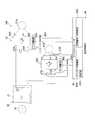
- FIG. 1 is a schematic configuration diagram of a heat pump type hot water heater 150 in which a motor control device 10 according to an embodiment of the present invention is mounted.
- a heat pump type hot water heater 150 is constituted by a heat pump unit 160 and a tank unit 180.
- the heat pump unit 160 is a vapor compression type in which an accumulator 161, a compressor 162, a refrigerant pipe 163a in the water heat exchanger 163, an expansion valve 164 as a decompression means, and an air heat exchanger 165 are connected in an annular shape by a refrigerant pipe.
- the refrigeration circuit 170 is provided.
- the refrigeration circuit 170 is provided with a liquid gas heat exchanger 167 for heat exchange between the high-pressure and high-temperature refrigerant coming out of the water heat exchanger 163 and the low-pressure and low-temperature refrigerant coming out of the air heat exchanger 165.
- a liquid gas heat exchanger 167 for heat exchange between the high-pressure and high-temperature refrigerant coming out of the water heat exchanger 163 and the low-pressure and low-temperature refrigerant coming out of the air heat exchanger 165.
- heat exchange is performed between the refrigerant passage connecting the water heat exchanger 163 and the expansion valve 164 and the refrigerant passage connecting the air heat exchanger 165 and the compressor 162.
- a fan 169 that blows air to the air heat exchanger 165 is disposed at a position facing the air heat exchanger 165.
- the tank unit 180 has a water circulation circuit 190 in which a tank 181, a water pipe 163 b in the water heat exchanger 163, and a water circulation pump 182 are annularly connected by a water circulation pipe.
- the microcomputer 40 controls the operation of the heat pump unit 160 and the tank unit 180.
- the motor control device 10 controls the motor 51A built in the compressor 162 and the motor 51B that drives the fan 169.
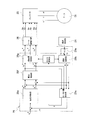
- FIG. 2 is a block diagram showing the system 100 when the system 100 related to the motor control device 10 is extracted from FIG.
- a motor 51A is a compressor motor and is built in a compressor 162 (see FIG. 1).
- the motor 51B is a fan motor and drives the fan 169 (see FIG. 1).
- the system 100 includes an inverter 25A that supplies a drive voltage to the motor 51A and an inverter 25B that supplies a drive voltage to the motor 51B.
- a DC voltage is supplied in parallel from one DC power supply unit 20 to the inverter 25A and the inverter 25B. That is, the positive side and the negative side of the DC bus are shared.
- a gate drive circuit 26A is connected to the inverter 25A, and a gate drive circuit 26B is connected to the inverter 25B.
- a sensorless control circuit 29A is connected to the gate drive circuit 26A, and a sensorless control circuit 29B is connected to the gate drive circuit 26B.
- the voltage detection unit 23A and the current detection unit 24A are connected to the sensorless control circuit 29A, and the voltage detection unit 23B and the current detection unit 24B are connected to the sensorless control circuit 29B.
- the microcomputer 40 is connected to an induced voltage detector 27B and sensorless control circuits 29A and 29B.
- the microcomputer 40 includes a compressor motor control unit 42A and a fan motor control unit 42B, and is connected to the overall control unit 41.
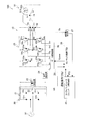
- FIG. 3 is a representative circuit diagram of the motor control device 10 in FIGS. 1 and 2.
- A is added to the end of the reference numerals of those related to the control of the motor 51A (compressor motor), and those related to the control of the motor 51B (fan motor) are shown.
- B is added to the end of the reference numeral, and voltage detectors 23A and 23B, current detectors 24A and 24B, inverters 25A and 25B, gate drive circuits 26A and 26B, induced voltage detector 27B, and sensorless control circuits 29A and 29B.
- the voltage detection unit 23, the current detection unit 24, the inverter 25, the gate drive circuit 26, and the induced voltage detection unit 27 from which “A” and “B” at the end are removed are described.
- the sensorless control circuit 29 is used.
- the motor 51 is a three-phase brushless DC motor, and includes a stator 511 and a rotor 513.
- the stator 511 includes U-phase, V-phase, and W-phase drive coils Lu, Lv, and Lw that are star-connected.
- One ends of the drive coils Lu, Lv, and Lw are connected to drive coil terminals TU, TV, and TW of U-phase, V-phase, and W-phase wirings extending from the inverter 25, respectively.
- the other ends of the drive coils Lu, Lv, and Lw are connected to each other as a terminal TN.
- These three-phase drive coils Lu, Lv, and Lw generate an induced voltage corresponding to the rotational speed and the position of the rotor 513 as the rotor 513 rotates.
- the rotor 513 includes a plurality of permanent magnets including N poles and S poles, and rotates about the rotation axis with respect to the stator 511.
- the rotation of the rotor 513 is output to a load via an output shaft (not shown) that is on the same axis as the rotation shaft.
- the motor 51 is a permanent magnet synchronous motor, and either an embedded magnet synchronous motor or a surface magnet synchronous motor is selected as appropriate, but an embedded magnet synchronous motor is recommended. This is because reluctance torque can be used in addition to magnet torque, and torque can be increased. Further, since the inductance changes depending on the position of the rotor 513, it is possible to estimate the starting position and perform the position sensorless operation in the extremely low speed region using this.
- the motor control device 10 includes a rectifier 21, a smoothing capacitor 22, a voltage detector 23, a current detector 24, an inverter 25, and a gate drive circuit 26 connected to a commercial power supply 91. And an induced voltage detector 27, a sensorless control circuit 29, and a microcomputer 40. These are mounted on, for example, one printed board.
- the rectifying unit 21 is configured in a bridge shape by four diodes D1a, D1b, D2a, and D2b. Specifically, the diodes D1a and D1b and D2a and D2b are respectively connected in series. The cathode terminals of the diodes D1a and D2a are both connected to the plus side terminal of the smoothing capacitor 22 and function as the positive side output terminal of the rectifying unit 21. The anode terminals of the diodes D1b and D2b are both connected to the negative side terminal of the smoothing capacitor 22 and function as the negative side output terminal of the rectifying unit 21.
- connection point of the diode D1a and the diode D1b is connected to one pole of the commercial power supply 91.
- a connection point between the diode D2a and the diode D2b is connected to the other pole of the commercial power supply 91.
- the rectifying unit 21 rectifies the AC voltage output from the commercial power supply 91 to generate a DC power supply, and supplies this to the smoothing capacitor 22.
- the smoothing capacitor 22 has one end connected to the positive output terminal of the rectifying unit 21 and the other end connected to the negative output terminal of the rectifying unit 21.
- the smoothing capacitor 22 smoothes the voltage rectified by the rectifying unit 21.
- this voltage is referred to as “DC voltage Vfl”.
- the DC voltage Vfl is applied to the inverter 25 connected to the output side of the smoothing capacitor 22. That is, the rectifying unit 21 and the smoothing capacitor 22 constitute a DC power supply unit 20 for the inverter 25.
- the smoothing capacitor 22 is appropriately selected from an electrolytic capacitor, a ceramic capacitor, a tantalum capacitor, and the like. In this embodiment, an electrolytic capacitor is employed.
- the voltage detector 23 is connected to the output side of the smoothing capacitor 22 and detects the voltage across the smoothing capacitor 22, that is, the value of the DC voltage Vfl.
- the voltage detector 23 is configured, for example, such that two resistors connected in series with each other are connected in parallel to the smoothing capacitor 22 and the DC voltage Vfl is divided. The voltage value at the connection point between the two resistors is input to the sensorless control circuit 29.
- the current detection unit 24 is connected between the smoothing capacitor 22 and the inverter 25 and connected to the negative output terminal side of the smoothing capacitor 22.
- the current detection unit 24 detects the motor current Im flowing through the motor 51 after the motor 51 is started.
- the current detection unit 24 may be composed of, for example, an amplifier circuit using a shunt resistor and an operational amplifier that amplifies the voltage across the resistor.
- the motor current detected by the current detection unit 24 is input to the sensorless control circuit 29.
- an inverter 25 is connected to the output side of the smoothing capacitor 22.
- an inverter 25 includes a plurality of insulated gate bipolar transistors (hereinafter simply referred to as transistors) Q3a, Q3b, Q4a, Q4b, Q5a, Q5b and a plurality of free-wheeling diodes D3a, D3b, D4a, D4b, D5a, Including D5b.
- transistors insulated gate bipolar transistors
- Transistors Q3a and Q3b, Q4a and Q4b, Q5a and Q5b are connected to each other in series.
- the transistors are connected in parallel so that the emitter terminal of the transistor and the anode terminal of the diode are connected.
- the inverter 25 is applied with the DC voltage Vfl from the smoothing capacitor 22, and the transistors Q3a to Q5b are turned on and off at the timing instructed by the gate drive circuit 26, whereby the drive voltages SU, SV and SW are generated.
- the drive voltages SU, SV, SW are output to the motor 51 from connection points NU, NV, NW of the transistors Q3a and Q3b, Q4a and Q4b, and Q5a and Q5b.
- Gate drive circuit 26 Based on the drive command value Vpwm from the sensorless control circuit 29, the gate drive circuit 26 changes the on and off states of the transistors Q3a to Q5b of the inverter 25. Specifically, the gate drive circuit 26 applies the drive voltages SU, SV, SW having the duty determined by the sensorless control circuit 29 to the gates of the transistors Q3a to Q5b so that the inverter 25 outputs the drive voltages SU, SV, SW to the motor 51.
- the gate control voltages Gu, Gx, Gv, Gy, Gw, and Gz to be applied are generated.
- the generated gate control voltages Gu, Gx, Gv, Gy, Gw, Gz are applied to the gate terminals of the respective transistors Q3a to Q5b.
- the induced voltage detector 27 is connected to the U-phase, V-phase, and W-phase drive coil terminals TU, TV, and TW of the motor 51, and the output is connected to the microcomputer 40.
- the induced voltage detector 27 detects the induced voltage Vn generated from the motor 51 when the motor 51 is rotating before the motor 51 is started.
- the microcomputer 40 calculates the rotational speed before starting of the motor 51 before starting based on the induced voltage Vn and estimates the rotor position.
- the technical significance of providing the induced voltage detection unit 27 is that the motor 51 is not energized without performing a predetermined mathematical model related to the control of the motor 51 or energizing the motor 51 as used when driving the motor in the rotor position sensorless control. And calculating the rotational speed before start-up and estimating the rotor position.
- the induced voltage detection unit 27 and the microcomputer 40 can detect the rotation speed before starting the motor 51 and the rotor position when the motor 51 is not started, that is, when the inverter 25 is not controlled. .
- the motor 51 is employed as a fan motor and the rotor position cannot be estimated by the rotor position sensorless control in which the fan is rotated by natural wind or the like, based on the detection value of the induced voltage detection unit 27.
- the rotation speed before starting can be obtained.
- the induced voltage detector 27 functions during a period from the start of the motor 51 until the motor 51 is driven by the rotor position sensorless control.
- the sensorless control circuit 29 is connected to the voltage detection unit 23, the current detection unit 24, the gate drive circuit 26, and the microcomputer 40.
- the sensorless control circuit 29 is a circuit that drives the motor 51 based on an operation command Vfg including a speed command sent from the microcomputer 40.
- the motor 51 is driven by rotor position sensorless control.
- the rotor position sensorless control uses various parameters indicating the characteristics of the motor 51, the result of the voltage detection unit 23 after starting the motor 51, the result of the current detection unit 24, a predetermined mathematical model related to the control of the motor 51, and the like. This is control for performing estimation of position and rotational speed, PI control for rotational speed, PI control for motor current, and the like. Examples of various parameters indicating the characteristics of the motor 51 include the winding resistance, inductance component, induced voltage, and number of poles of the motor 51 used.
- Microcomputer 40 The microcomputer 40 is connected to the sensorless control circuit 29.
- the microcomputer 40 is also connected to an overall control unit 41 (see FIGS. 1 and 2) that controls each device in an integrated manner, and controls the driving of the motor 51 in accordance with the presence or absence of an abnormality in each device. . Therefore, the microcomputer 40 functions as a determination unit, and the determination unit 421 is actually provided.
- the negative side of the microcomputer power supply has a common potential as the negative side of the DC bus, the GND of the voltage detection unit, and the current detection unit.
- the microcomputer 40 compares the rotation speed before start-up with a predetermined rotation speed, and determines whether or not the pre-start-up rotation speed is equal to or higher than the predetermined rotation speed. If the rotation speed before startup is equal to or higher than the predetermined rotation speed, the motor 51B is already rotating at a sufficient rotation speed due to the influence of wind or the like, and therefore the air heat exchanger 165 (see FIG. 1) is not required to start the motor 51B. ) Is sufficiently supplied with air, the microcomputer 40 maintains a state in which the motor 51B is not activated.
- the motor 51B driven by the rotor position sensorless control does not know the position of the rotor 513 at the start-up time when the motor is not rotating, a synchronous operation for forcibly rotating the motor 51B regardless of the position of the rotor 513 is performed.
- the drive of the motor 51B is switched to the rotor position sensorless control.
- the motor is rotating at a sufficiently high rotational speed and the induced voltage can be estimated by detecting the induced voltage by the induced voltage detector, first the motor is started using the estimated rotor position, and then The drive of the motor 51B is switched to the rotor position sensorless control.
- FIG. 4 is a flowchart of current vector control for estimating the rotor position without a sensor.
- the AD converter 29a measures the voltage value output from the current detection unit 24 and takes the three-phase current values (Iu, Iv, Iw) in consideration of the switching state. calculate.
- the coordinate conversion unit 29b converts the three-phase current values (Iu, Iv, Iw) into dq-axis currents (Id, Iq).
- the rotor position estimation unit 29c calculates the angular velocity ⁇ and the electrical angle ⁇ of the rotor 513.
- the speed control unit 29e calculates current command values (Id * , Iq * ) by PI control from the target angular speed ⁇ * and the actual angular speed ⁇ .
- the current control unit 29f calculates a dq axis voltage command value (Vd * , Vq * ) by PI control from the current command value (Id * , Iq * ) and the actual current value (Id, Iq).
- the inverse coordinate conversion unit 29g converts the dq axis voltage command value (Vd * , Vq * ) into a three-phase voltage (Vu * , Vv * , Vw * ), and drives the gate as the drive command value Vpwm from the sensorless control circuit 29. Output to the circuit 26.
- the gate drive circuit 26 applies the gate control voltages Gu, Gx, Gv, Gy, Gw, Gz generated based on the drive command value Vpwm from the sensorless control circuit 29 to the gates of the transistors Q3a to Q5b, and the inverter 25 The on and off states of the transistors Q3a to Q5b are changed.
- the motor 51B driven by the rotor position sensorless control forcibly rotates the motor 51B regardless of the position of the rotor 513 because the position of the rotor 513 is not known at the start when the motor is not rotating.
- the motor 51B is driven by the rotor position sensorless control after the motor is started by performing the synchronous operation to increase the motor current and the position of the rotor 513 can be estimated stably.
- noise is added to the detection value for detecting the position of the rotor 513 of the motor 51B, and accurate position detection cannot be performed, which may cause startup abnormality. . This is particularly noticeable when the negative side of the DC bus is used as a common GND potential.
- the motor control device 10 avoids the start abnormality of the motor 51B by performing start prohibition control that does not start the motor 51B when performing a predetermined operation in which a large current flows through the motor 51A.
- FIG. 5 is a flowchart of start-up control including start prohibition control.
- the fan motor control unit 42B on the motor 51B side determines whether or not there is a start command for the motor 51B from the overall control unit 41 in step S1, and if there is a start command, proceeds to step S2 to start When there is no command, the start command is continuously monitored.
- the fan motor control unit 42B detects the rotation speed Np of the motor 51B before starting in step S2, and proceeds to step S3.
- the fan motor control unit 42B determines whether or not the rotation speed Np before activation of the motor 51B is smaller than the predetermined rotation speed Ns prior to activation of the motor 51B in step S3. If Np ⁇ Ns, step S4 is performed. If Np ⁇ Ns, the process proceeds to step S13.
- step S4 determines in step S4 whether or not the motor 51A (compressor motor) is in a predetermined operation. If the motor 51A is in a predetermined operation, the process proceeds to step S5, and the motor 51A Is not in a predetermined operation, the process proceeds to step S8 to start the starting operation of the motor 51B.
- motor 51A compressor motor
- the predetermined operation of the motor 51A is any one of the synchronous operation of the compressor 162, the torque control of the compressor 162, and the overload operation of the compressor 162. Since a voltage is applied regardless of the rotor position during synchronous operation, in addition to requiring a large current to rotate the rotor in a synchronous state, a reactive current flows due to a current phase shift, and a regenerative operation is performed. The influence on the fluctuation of the negative potential of the DC bus which is a common potential with the voltage detection unit / current detection unit is great. Further, during torque control, in order to suppress torque fluctuation depending on the structure and operation of the compressor, current fluctuation occurs in synchronization with torque fluctuation, and a large current flows. Needless to say, a large current flows during overload operation. In the present embodiment, the start prohibition control (steps S5 to S7) during the first motor predetermined operation is performed by setting the time when a large current flows as described above as the predetermined operation.
- step S5 the fan motor control unit 42B waits for a predetermined time t1 without starting the motor 51B in step S5, and proceeds to step S6.
- the fan motor control unit 42B determines whether or not the predetermined time t1 has elapsed in step S6. When the predetermined time t1 has elapsed, the process proceeds to step S7, and when the predetermined time t1 has not elapsed. Will continue to time.
- step S7 the fan motor control unit 42B determines whether or not the predetermined operation of the motor 51A has ended in step S7.
- the process proceeds to step S8, and the predetermined operation of the motor 51A ends. If not, the process returns to step S5.
- fan motor control part 42B starts the starting operation of motor 51B in Step S8.
- step S3 When the fan motor control unit 42B determines that Np ⁇ Ns in step S3 and proceeds to step S13, the motor 51B is not activated and waits for a predetermined time t2, and then proceeds to step S14.
- the fan motor control unit 42B determines whether or not the predetermined time t2 has elapsed in step S14, returns to step S2 when the predetermined time t2 has elapsed, and returns to step S2 when the predetermined time t2 has not elapsed. Continue to time.
- the startup control of the motor 51B includes startup prohibition control, and priority is given to startup without being affected by the predetermined operation of the motor 51A.
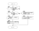
- FIG. 6 is a flowchart of the abnormality detection control. As shown in FIG. 6, the fan motor control unit 42B on the motor 51B side determines whether or not the motor 51B is operating abnormally in step S21. If it is determined “abnormal”, the process proceeds to step S22 and “no abnormality”. If it is determined that the operation is abnormal, the operation is continuously monitored for abnormalities.
- the fan motor control unit 42B determines whether or not the motor 51A (compressor motor) is in a predetermined operation in step S22. If the motor 51A is in a predetermined operation, the process proceeds to step S23, and the motor 51A When is not in a predetermined operation, the process proceeds to step S32.
- the motor 51A compressor motor
- the predetermined operation of the motor 51A is any one of the synchronous operation of the compressor 162, the torque control of the compressor 162, and the overload operation of the compressor 162.
- the fan motor control unit 42B cancels the “abnormality” determination in step S21 in step S23, and proceeds to step S24.
- the fan motor control unit 42B performs a retry of the control object determined to be abnormal in step S21 in step S24. For example, even if an abnormal value is detected in the inverter current of the motor 51B, there is a high possibility that it is a false detection due to noise and is transient, so that the inverter operation is retried without counting as an abnormality. Suppresses unnecessary abnormal stopping of the motor.
- an abnormality detection means that the fan motor control unit 42B has detected an abnormality in step S32.
- the signal is transmitted to the overall control unit 41.
- the overall control unit 41 receives the abnormality detection signal, it determines to stop the system 100 and / or notify the abnormality, and sends a command to the fan motor control unit 42B.
- the fan motor control part 42B performs the notification which shows the stop and / or abnormality of the system 100 in step S33.
- the motor control device 10 can suppress an unnecessary abnormal stop of the motor 51B by canceling the abnormality determination and continuing the operation.
- the fan motor control unit 42B determines whether or not there is an abnormality during the operation of the motor 51B in step S21, but the operation of the motor 51B may be limited to the startup operation. Especially when starting from a reverse rotation state, such as in a reverse wind, the current detection and start operation when the rotation direction changes are likely to be unstable. In particular, the effects of the present application can be obtained.
- the motor 51B (fan motor) may be operated with a large current.
- the motor 51A compressor motor
- the synchronous operation abnormality of the motor 51A can be avoided by avoiding the synchronous operation of the motor 51A when the fan 169 is activated by the reverse wind.
- the combination of the motors is not limited to this example, and the same effect can be obtained even if the motors 51A and 51B are compressor motors.
- the motors 51A and 51B are fan motors, or when the motor 51A is a fan motor and the motor 51B is a compressor motor, the same effect can be obtained.
- the motor is a motor other than the compressor motor or fan motor, for example, a pump motor.
- the motor control device according to the present invention is useful not only for a heat pump type water heater but also for an air conditioner.
Abstract
Description
図1は、本発明の一実施形態に係るモータ制御装置10が搭載されているヒートポンプ式給湯機150の概略構成図である。図1おいて、ヒートポンプ式給湯機150は、ヒートポンプユニット160とタンクユニット180とによって構成されている。
図2は、図1からモータ制御装置10に関連するシステム100を抜き出した場合の当該システム100を示すブロック図である。図2において、モータ51Aは圧縮機モータであり圧縮機162(図1参照)に内蔵されている。モータ51Bはファンモータであり、ファン169(図1参照)を駆動する。システム100は、モータ51Aに駆動電圧を供給するインバータ25A、及びモータ51Bに駆動電圧を供給するインバータ25Bを備えている。
モータ51は、3相のブラシレスDCモータであって、ステータ511と、ロータ513とを備えている。ステータ511は、スター結線されたU相、V相及びW相の駆動コイルLu,Lv,Lwを含む。各駆動コイルLu,Lv,Lwの一方端は、それぞれインバータ25から延びるU相、V相及びW相の各配線の駆動コイル端子TU,TV,TWに接続されている。各駆動コイルLu,Lv,Lwの他方端は、互いに端子TNとして接続されている。これら3相の駆動コイルLu,Lv,Lwは、ロータ513が回転することによりその回転速度とロータ513の位置に応じた誘起電圧を発生させる。
モータ制御装置10は、図3に示すように、商用電源91に接続された整流部21と、平滑コンデンサ22と、電圧検出部23と、電流検出部24と、インバータ25と、ゲート駆動回路26と、誘起電圧検出部27と、センサレス制御回路29と、マイクロコンピュータ40とを備えている。これらは、例えば1枚のプリント基板上に実装される。
(2-1)整流部21
整流部21は、4つのダイオードD1a,D1b,D2a,D2bによってブリッジ状に構成されている。具体的には、ダイオードD1aとD1b、D2aとD2bは、それぞれ互いに直列に接続されている。ダイオードD1a,D2aの各カソード端子は、共に平滑コンデンサ22のプラス側端子に接続されており、整流部21の正側出力端子として機能する。ダイオードD1b,D2bの各アノード端子は、共に平滑コンデンサ22のマイナス側端子に接続されており、整流部21の負側出力端子として機能する。
平滑コンデンサ22は、一端が整流部21の正側出力端子に接続され、他端が整流部21の負側出力端子に接続されている。平滑コンデンサ22は、整流部21によって整流された電圧を平滑する。以下、説明の便宜上、この電圧を“直流電圧Vfl”という。
電圧検出部23は、平滑コンデンサ22の出力側に接続されており、平滑コンデンサ22の両端電圧、即ち直流電圧Vflの値を検出するためのものである。電圧検出部23は、例えば、互いに直列に接続された2つの抵抗が平滑コンデンサ22に並列接続され、直流電圧Vflが分圧されるように構成される。それら2つの抵抗同士の接続点の電圧値は、センサレス制御回路29に入力される。
電流検出部24は、平滑コンデンサ22及びインバータ25の間であって、かつ平滑コンデンサ22の負側出力端子側に接続されている。電流検出部24は、モータ51の起動後、モータ51に流れるモータ電流Imを検出する。
インバータ25は、平滑コンデンサ22の出力側に接続される。図3において、インバータ25は、複数の絶縁ゲート型バイポーラトランジスタ(以下、単にトランジスタという)Q3a,Q3b,Q4a,Q4b,Q5a,Q5b及び複数の還流用のダイオードD3a,D3b,D4a,D4b,D5a,D5bを含む。
ゲート駆動回路26は、センサレス制御回路29からの駆動指令値Vpwmに基づき、インバータ25の各トランジスタQ3a~Q5bのオン及びオフの状態を変化させる。具体的には、ゲート駆動回路26は、センサレス制御回路29によって決定されたデューティを有する駆動電圧SU,SV,SWがインバータ25からモータ51に出力されるように、各トランジスタQ3a~Q5bのゲートに印加するゲート制御電圧Gu,Gx,Gv,Gy,Gw,Gzを生成する。生成されたゲート制御電圧Gu,Gx,Gv,Gy,Gw,Gzは、それぞれのトランジスタQ3a~Q5bのゲート端子に印加される。
誘起電圧検出部27は、入力がモータ51のU相,V相,W相の駆動コイル端子TU,TV,TWと接続されており、出力がマイクロコンピュータ40に接続されている。この誘起電圧検出部27は、モータ51の起動前においてモータ51が回転している際に、モータ51から発生する誘起電圧Vnを検出する。マイクロコンピュータ40は、この誘起電圧Vnに基づいて起動前のモータ51の起動前回転数を演算すると共に、ロータ位置を推定する。
センサレス制御回路29は、電圧検出部23、電流検出部24、ゲート駆動回路26及びマイクロコンピュータ40と接続されている。センサレス制御回路29は、マイクロコンピュータ40から送られてきた速度指令を含む運転指令Vfgに基づいて、モータ51を駆動させる回路である。
マイクロコンピュータ40は、センサレス制御回路29と接続されている。また、マイクロコンピュータ40は、各機器を統括して制御する統括制御部41(図1及び図2参照)とも接続されており、各機器における異常の有無に応じて、モータ51の駆動を制御する。それゆえ、マイクロコンピュータ40は、判断部として機能し、実際に判断部421が設けられている。
モータ51Bの起動前には、マイクロコンピュータ40は起動前回転数と所定回転数とを比較し、起動前回転数が所定回転数以上か否かを判断する。起動前回転数が所定回転数以上であれば、既に風等の影響によりモータ51Bが十分な回転数で回転しているので、あえてモータ51Bを起動させずとも空気熱交換器165(図1参照)には十分な空気が送られていることから、マイクロコンピュータ40はモータ51Bを起動させない状態を維持する。
図4は、センサレスでロータ位置を推定するための電流ベクトル制御のフローチャートである。図4において、センサレス制御回路29では、A-Dコンバータ29aが電流検出部24から出力された電圧値を測定し、スイッチングの状態を考慮して3相の電流値(Iu,Iv,Iw)を算出する。
ロータ位置センサレス制御で駆動されるモータ51Bは、モータが回転していない場合の起動時にはロータ513の位置がわからないので、ロータ513の位置に関係なく強制的にモータ51Bを回転させる同期運転を行なってモータを起動させ、モータ電流が増加してロータ513の位置を安定して推定できるようになってから、モータ51Bをロータ位置センサレス制御で駆動する。そのような起動時に他のモータ51Aに大電流が流れることによって、モータ51Bのロータ513の位置検出のための検出値にノイズがのり、正確な位置検出ができなくなり、起動異常を招く虞がある。とりわけ、DCバスの負側を共通のGND電位として用いている場合に顕著である。
圧縮機162の同期運転、圧縮機162のトルク制御、圧縮機162の過負荷運転では、モータ51A(圧縮機モータ)に大電流が流れるので、モータ51B(ファンモータ)の制御において、制御結果が異常と判定されることがある。その際、異常として扱うと、実際には異常ではないにもかかわらず、運転停止を余儀なくされるので望ましくない。上記のような問題に鑑みて、本実施形態では、以下のような異常検出時制御を行っている。
(7-1)
モータ制御装置10では、モータ51A(圧縮機モータ)に大電流が流れる所定運転を行っているときにモータ51B(ファンモータ)を起動させないことによって、モータ51Bの起動異常を回避することができる。
モータ51A(圧縮機モータ)の運転時に大電流が流れることによって、モータ51B側のインバータ電流の検出値にノイズがのるので、異常判定の頻度が高まる。しかし、このときの異常検出は損傷に至る異常ではなく、ノイズによる誤検知であり過渡的なものであるので、その異常判定に従ってその都度モータを停止させると正常運転を妨げることになる。しかし、モータ制御装置10では、異常判定を取り消して運転を継続させることによって、モータ51Bの不要な異常停止を抑制することができる。
モータ制御装置10では、モータ51A(圧縮機モータ)が所定運転を行っているとき、例えば、モータ51B側のインバータ電流に異常値を検出しても、ノイズによる誤検知であり過渡的なものである可能性が高いので、異常としてカウントせずにインバータ電流の検出リトライ、及びインバータ運転のリトライを行わせることによって、モータ51Bの不要な異常停止を抑制する。
モータ制御装置10では、圧縮機162を回転させるモータ51Aがロータ位置センサレス制御で駆動される場合において、モータ51Aの同期運転中にモータ51Bを起動させることを避けることによって、モータ51Bの起動異常を回避することができる。
(8-1)
図5の異常検出時制御のフローチャートでは、ファンモータ制御部42BがステップS21においてモータ51Bの運転中の異常の有無を判定するとしているが、モータ51Bの運転を起動運転に限定してもよい。特に逆風時などの、逆回転状態からの起動時には、回転方向変化時の電流検出や起動動作が不安定となりやすいため、正回転方向で所定回転数以上となるまでの起動運転時に限定することで、特に本願の効果を得ることができる。
上記実施形態では、モータ51A(圧縮機モータ)に大電流を伴う所定運転をさせているとき、モータ51B(ファンモータ)の運転への影響を抑制する制御を例に説明した。
上記実施形態では、モータ51Aが圧縮機モータで、モータ51Bがファンモータである場合を例に説明した。
20 電源供給部
25A インバータ
25B インバータ
40 制御部
41 統括制御部
51A モータ(第1モータ)
51B モータ(第2モータ)
162 圧縮機
421 判断部
Claims (5)
- 第1回転体を回転させる第1モータ(51A)、及び第2回転体を回転させる第2モータ(51B)を駆動するモータ制御装置であって、
電源供給部(20)と、
前記電源供給部(20)からの出力を交流に変換して前記第1モータ(51A)及び前記第2モータ(51B)に供給するインバータ(25A,25B)と、
前記第2モータ(51B)をロータ位置センサレス制御によって駆動する制御部(40)を備え、
前記制御部(40)は、前記第1モータ(51A)に大電流が流れる所定運転を行っているとき、前記第2モータ(51B)を起動させない、
モータ制御装置(10)。 - 第1回転体を回転させる第1モータ(51A)、及び第2回転体を回転させる第2モータ(51B)を駆動するモータ制御装置であって、
電源供給部(20)と、
前記電源供給部(20)からの出力を交流に変換して前記第1モータ(51A)及び前記第2モータ(51B)に供給するインバータ(25A,25B)と、
前記第2モータ(51B)をロータ位置センサレス制御によって駆動する制御部(40)を備え、
前記制御部(40)は、前記第2モータ(51B)が異常状態であるか否か判断する判断部(421)を有し、
さらに、前記制御部(40)は、前記第2モータ(51B)の運転中で前記第1モータ(51A)が所定運転を行っているとき、前記判断部(421)が前記第2モータ(51B)側の前記インバータ(25B)を異常状態であると判断しても、前記判断部(421)の判定を取り消す、
モータ制御装置(10)。 - 第1回転体を回転させる第1モータ(51A)、及び第2回転体を回転させる第2モータ(51B)を駆動するモータ制御装置であって、
電源供給部(20)と、
前記電源供給部(20)からの出力を交流に変換して前記第1モータ(51A)及び前記第2モータ(51B)に供給するインバータ(25A,25B)と、
前記第2モータ(51B)をロータ位置センサレス制御によって駆動する制御部(40)と、
前記制御部(40)を含む2以上の制御部を統括する統括制御部(41)と、
を備え、
前記制御部(40)は、前記第2モータ(51B)が異常状態であるか否か判断する判断部(421)を有し、
さらに、前記制御部(40)は、前記第2モータ(51B)の運転中で前記第1モータ(51A)が所定運転を行っているとき、前記判断部(421)が前記第2モータ(51B)側の前記インバータ(25B)を異常状態であると判断しても、異常状態である旨の報知を前記統括制御部(41)に行わず、前記インバータ(25B)の運転リトライ動作を行う、
モータ制御装置(10)。 - 前記第2モータ(51B)の運転が、起動運転である、
請求項2又は請求項3に記載のモータ制御装置(10)。 - 前記第1回転体が圧縮機であって、前記第1モータ(51A)がロータ位置センサレス制御で駆動される場合において、
前記第1モータ(51A)の前記所定運転は、前記圧縮機の同期運転である、
請求項1から請求項4のいずれか1項に記載のモータ制御装置(10)。
Priority Applications (5)
| Application Number | Priority Date | Filing Date | Title |
|---|---|---|---|
| AU2015205234A AU2015205234B2 (en) | 2014-01-10 | 2015-01-06 | Motor control device |
| ES15735189T ES2792599T3 (es) | 2014-01-10 | 2015-01-06 | Dispositivo de control de motor |
| EP15735189.1A EP3093983B1 (en) | 2014-01-10 | 2015-01-06 | Motor control device |
| CN201580003812.4A CN105900330B (zh) | 2014-01-10 | 2015-01-06 | 电机控制装置 |
| US15/110,303 US9929682B2 (en) | 2014-01-10 | 2015-01-06 | Motor control device |
Applications Claiming Priority (2)
| Application Number | Priority Date | Filing Date | Title |
|---|---|---|---|
| JP2014003769A JP5858058B2 (ja) | 2014-01-10 | 2014-01-10 | モータ制御装置 |
| JP2014-003769 | 2014-01-10 |
Publications (1)
| Publication Number | Publication Date |
|---|---|
| WO2015105100A1 true WO2015105100A1 (ja) | 2015-07-16 |
Family
ID=53523925
Family Applications (1)
| Application Number | Title | Priority Date | Filing Date |
|---|---|---|---|
| PCT/JP2015/050157 WO2015105100A1 (ja) | 2014-01-10 | 2015-01-06 | モータ制御装置 |
Country Status (7)
| Country | Link |
|---|---|
| US (1) | US9929682B2 (ja) |
| EP (1) | EP3093983B1 (ja) |
| JP (1) | JP5858058B2 (ja) |
| CN (1) | CN105900330B (ja) |
| AU (1) | AU2015205234B2 (ja) |
| ES (1) | ES2792599T3 (ja) |
| WO (1) | WO2015105100A1 (ja) |
Families Citing this family (7)
| Publication number | Priority date | Publication date | Assignee | Title |
|---|---|---|---|---|
| KR102436704B1 (ko) * | 2015-03-23 | 2022-08-25 | 엘지전자 주식회사 | 팬 모터 구동장치 및 이를 구비하는 공기조화기 |
| CN107925375B (zh) * | 2015-10-19 | 2020-10-13 | 三菱电机株式会社 | 空气调节机 |
| JP6393287B2 (ja) * | 2016-01-27 | 2018-09-19 | 日立ジョンソンコントロールズ空調株式会社 | 空気調和機の室外機 |
| US10396694B2 (en) * | 2016-03-17 | 2019-08-27 | General Electric Company | System and method for minimizing reactive current to limit rotor modulation index on a power converter |
| JP6710565B2 (ja) * | 2016-04-12 | 2020-06-17 | 株式会社東芝 | モータ制御装置 |
| DK179590B1 (en) * | 2017-03-14 | 2019-02-21 | OJ Electronics A/S | DRIVE BELT DETECTOR |
| WO2021212520A1 (zh) * | 2020-04-24 | 2021-10-28 | 深圳市大疆创新科技有限公司 | 电机的控制方法、装置、设备及存储介质 |
Citations (3)
| Publication number | Priority date | Publication date | Assignee | Title |
|---|---|---|---|---|
| JP2001129293A (ja) * | 1999-11-09 | 2001-05-15 | Matsushita Electric Ind Co Ltd | 洗濯機の制御装置 |
| JP2008054811A (ja) * | 2006-08-30 | 2008-03-13 | Matsushita Electric Ind Co Ltd | 洗濯乾燥機のモータ駆動装置 |
| JP2012159270A (ja) | 2011-02-02 | 2012-08-23 | Daikin Industries Ltd | 制御装置及びヒートポンプ装置 |
Family Cites Families (18)
| Publication number | Priority date | Publication date | Assignee | Title |
|---|---|---|---|---|
| US2526924A (en) * | 1949-05-04 | 1950-10-24 | York Corp | Current inrush control |
| JPS58172983A (ja) * | 1982-03-31 | 1983-10-11 | Toshiba Corp | 複数台交流電動機駆動装置 |
| JPS60168092A (ja) * | 1984-02-13 | 1985-08-31 | 株式会社日立製作所 | 原子炉のインタ−ナルポンプ起動方法 |
| JPH01137168A (ja) * | 1987-11-20 | 1989-05-30 | Toshiba Corp | 空気調和機 |
| TW328190B (en) * | 1994-06-14 | 1998-03-11 | Toshiba Co Ltd | Control device of brushless motor and method of fault detection and air conditioner |
| US7026772B2 (en) * | 2004-01-14 | 2006-04-11 | International Rectifier Corporation | Position sensorless drive for permanent magnet synchronous motors |
| JP4682727B2 (ja) * | 2005-07-13 | 2011-05-11 | パナソニック株式会社 | モータ駆動装置 |
| JP4988374B2 (ja) * | 2007-02-15 | 2012-08-01 | 三洋電機株式会社 | モータ制御装置 |
| JP4428440B2 (ja) * | 2007-05-28 | 2010-03-10 | 株式会社デンソー | ロータ位置検出回路,モータ駆動装置及びロータ位置検出方法 |
| DE112009001967T5 (de) * | 2008-12-24 | 2011-07-14 | Aisin AW Co., Ltd., Aichi-ken | Motorsteuervorrichtung und Antriebsvorrichtung für ein Hybridfahrzeug |
| JP5422468B2 (ja) * | 2010-04-01 | 2014-02-19 | 日立オートモティブシステムズ株式会社 | 電力変換装置 |
| JP5866763B2 (ja) * | 2011-02-02 | 2016-02-17 | ダイキン工業株式会社 | モータ駆動制御装置 |
| JP5798838B2 (ja) * | 2011-08-22 | 2015-10-21 | 日立アプライアンス株式会社 | モータ制御装置 |
| JP5260719B2 (ja) * | 2011-11-30 | 2013-08-14 | ファナック株式会社 | 停電の有無を判定する停電判定部を有するモータ駆動装置 |
| JP5622053B2 (ja) * | 2012-02-09 | 2014-11-12 | 株式会社デンソー | 多相回転機の制御装置、および、これを用いた電動パワーステアリング装置 |
| JP5614661B2 (ja) * | 2012-10-09 | 2014-10-29 | 株式会社デンソー | 回転電機制御装置、および、これを用いた電動パワーステアリング装置 |
| JP2014121215A (ja) * | 2012-12-18 | 2014-06-30 | Honda Motor Co Ltd | 負荷駆動制御装置 |
| JP5628954B2 (ja) * | 2013-03-29 | 2014-11-19 | ファナック株式会社 | 複数のモータを同期制御するモータ制御装置 |
-
2014
- 2014-01-10 JP JP2014003769A patent/JP5858058B2/ja active Active
-
2015
- 2015-01-06 US US15/110,303 patent/US9929682B2/en active Active
- 2015-01-06 ES ES15735189T patent/ES2792599T3/es active Active
- 2015-01-06 EP EP15735189.1A patent/EP3093983B1/en active Active
- 2015-01-06 CN CN201580003812.4A patent/CN105900330B/zh active Active
- 2015-01-06 WO PCT/JP2015/050157 patent/WO2015105100A1/ja active Application Filing
- 2015-01-06 AU AU2015205234A patent/AU2015205234B2/en active Active
Patent Citations (3)
| Publication number | Priority date | Publication date | Assignee | Title |
|---|---|---|---|---|
| JP2001129293A (ja) * | 1999-11-09 | 2001-05-15 | Matsushita Electric Ind Co Ltd | 洗濯機の制御装置 |
| JP2008054811A (ja) * | 2006-08-30 | 2008-03-13 | Matsushita Electric Ind Co Ltd | 洗濯乾燥機のモータ駆動装置 |
| JP2012159270A (ja) | 2011-02-02 | 2012-08-23 | Daikin Industries Ltd | 制御装置及びヒートポンプ装置 |
Non-Patent Citations (1)
| Title |
|---|
| See also references of EP3093983A4 * |
Also Published As
| Publication number | Publication date |
|---|---|
| CN105900330B (zh) | 2019-11-22 |
| EP3093983B1 (en) | 2020-02-26 |
| ES2792599T3 (es) | 2020-11-11 |
| EP3093983A4 (en) | 2017-01-18 |
| CN105900330A (zh) | 2016-08-24 |
| AU2015205234A1 (en) | 2016-08-11 |
| US20160329844A1 (en) | 2016-11-10 |
| JP2015133819A (ja) | 2015-07-23 |
| US9929682B2 (en) | 2018-03-27 |
| EP3093983A1 (en) | 2016-11-16 |
| AU2015205234B2 (en) | 2017-08-17 |
| JP5858058B2 (ja) | 2016-02-10 |
Similar Documents
| Publication | Publication Date | Title |
|---|---|---|
| JP5858058B2 (ja) | モータ制御装置 | |
| US9444377B2 (en) | Motor drive control device | |
| JP5539928B2 (ja) | モータ駆動装置、それを用いたファン制御装置およびヒートポンプ装置 | |
| JP2004201425A (ja) | モータ温度推定装置及び圧縮機内部状態推定装置 | |
| JP2019140778A (ja) | モータ制御装置、欠相検出装置、及びモータ制御装置の欠相検出方法 | |
| WO2017126639A1 (ja) | 電流センサの異常検知装置 | |
| JP5778045B2 (ja) | 同期モータの駆動装置、及びこれを用いた冷凍装置、空気調和機、冷蔵庫、並びに同期モータの駆動方法 | |
| JP7023387B2 (ja) | モータ制御装置および空気調和装置 | |
| JP5866763B2 (ja) | モータ駆動制御装置 | |
| JP6463966B2 (ja) | モータ駆動装置およびモータ駆動用モジュール並びに冷凍機器 | |
| JP2009225596A (ja) | 電動機の駆動装置、空気調和機、洗濯機、洗濯乾燥機、冷蔵庫、換気扇、ヒートポンプ給湯器 | |
| JP2012161214A5 (ja) | ||
| JP2004147430A (ja) | 電動機のセンサレス駆動制御方法及び駆動制御システム | |
| JP5422435B2 (ja) | ブラシレスモータの駆動装置および駆動方法 | |
| JP2014007916A (ja) | モータ制御装置 | |
| JP2003348885A (ja) | 永久磁石型同期モータの制御方法及び制御装置 | |
| JP6925527B2 (ja) | モータ駆動装置、モータ駆動装置の制御装置、モータ駆動装置の制御方法、及び空気調和機 | |
| JP2012161213A (ja) | モータ駆動装置 | |
| JP2010051151A (ja) | モータ制御装置 | |
| JP2015154703A (ja) | モータ制御装置 | |
| JP2017184371A (ja) | モータ駆動装置 |
Legal Events
| Date | Code | Title | Description |
|---|---|---|---|
| 121 | Ep: the epo has been informed by wipo that ep was designated in this application |
Ref document number: 15735189 Country of ref document: EP Kind code of ref document: A1 |
|
| WWE | Wipo information: entry into national phase |
Ref document number: 15110303 Country of ref document: US |
|
| NENP | Non-entry into the national phase |
Ref country code: DE |
|
| REEP | Request for entry into the european phase |
Ref document number: 2015735189 Country of ref document: EP |
|
| WWE | Wipo information: entry into national phase |
Ref document number: 2015735189 Country of ref document: EP |
|
| ENP | Entry into the national phase |
Ref document number: 2015205234 Country of ref document: AU Date of ref document: 20150106 Kind code of ref document: A |