WO2015104909A1 - 内燃機関のノッキング判定装置及びノッキング制御装置 - Google Patents
内燃機関のノッキング判定装置及びノッキング制御装置 Download PDFInfo
- Publication number
- WO2015104909A1 WO2015104909A1 PCT/JP2014/081002 JP2014081002W WO2015104909A1 WO 2015104909 A1 WO2015104909 A1 WO 2015104909A1 JP 2014081002 W JP2014081002 W JP 2014081002W WO 2015104909 A1 WO2015104909 A1 WO 2015104909A1
- Authority
- WO
- WIPO (PCT)
- Prior art keywords
- knocking
- internal combustion
- combustion engine
- knock
- value
- Prior art date
Links
Images

Classifications
-
- F—MECHANICAL ENGINEERING; LIGHTING; HEATING; WEAPONS; BLASTING
- F02—COMBUSTION ENGINES; HOT-GAS OR COMBUSTION-PRODUCT ENGINE PLANTS
- F02D—CONTROLLING COMBUSTION ENGINES
- F02D35/00—Controlling engines, dependent on conditions exterior or interior to engines, not otherwise provided for
- F02D35/02—Controlling engines, dependent on conditions exterior or interior to engines, not otherwise provided for on interior conditions
- F02D35/027—Controlling engines, dependent on conditions exterior or interior to engines, not otherwise provided for on interior conditions using knock sensors
-
- F—MECHANICAL ENGINEERING; LIGHTING; HEATING; WEAPONS; BLASTING
- F02—COMBUSTION ENGINES; HOT-GAS OR COMBUSTION-PRODUCT ENGINE PLANTS
- F02D—CONTROLLING COMBUSTION ENGINES
- F02D35/00—Controlling engines, dependent on conditions exterior or interior to engines, not otherwise provided for
- F02D35/02—Controlling engines, dependent on conditions exterior or interior to engines, not otherwise provided for on interior conditions
- F02D35/023—Controlling engines, dependent on conditions exterior or interior to engines, not otherwise provided for on interior conditions by determining the cylinder pressure
-
- F—MECHANICAL ENGINEERING; LIGHTING; HEATING; WEAPONS; BLASTING
- F02—COMBUSTION ENGINES; HOT-GAS OR COMBUSTION-PRODUCT ENGINE PLANTS
- F02D—CONTROLLING COMBUSTION ENGINES
- F02D41/00—Electrical control of supply of combustible mixture or its constituents
- F02D41/02—Circuit arrangements for generating control signals
- F02D41/04—Introducing corrections for particular operating conditions
- F02D41/042—Introducing corrections for particular operating conditions for stopping the engine
-
- F—MECHANICAL ENGINEERING; LIGHTING; HEATING; WEAPONS; BLASTING
- F02—COMBUSTION ENGINES; HOT-GAS OR COMBUSTION-PRODUCT ENGINE PLANTS
- F02D—CONTROLLING COMBUSTION ENGINES
- F02D41/00—Electrical control of supply of combustible mixture or its constituents
- F02D41/02—Circuit arrangements for generating control signals
- F02D41/04—Introducing corrections for particular operating conditions
- F02D41/12—Introducing corrections for particular operating conditions for deceleration
-
- F—MECHANICAL ENGINEERING; LIGHTING; HEATING; WEAPONS; BLASTING
- F02—COMBUSTION ENGINES; HOT-GAS OR COMBUSTION-PRODUCT ENGINE PLANTS
- F02D—CONTROLLING COMBUSTION ENGINES
- F02D41/00—Electrical control of supply of combustible mixture or its constituents
- F02D41/22—Safety or indicating devices for abnormal conditions
-
- F—MECHANICAL ENGINEERING; LIGHTING; HEATING; WEAPONS; BLASTING
- F02—COMBUSTION ENGINES; HOT-GAS OR COMBUSTION-PRODUCT ENGINE PLANTS
- F02D—CONTROLLING COMBUSTION ENGINES
- F02D41/00—Electrical control of supply of combustible mixture or its constituents
- F02D41/24—Electrical control of supply of combustible mixture or its constituents characterised by the use of digital means
- F02D41/26—Electrical control of supply of combustible mixture or its constituents characterised by the use of digital means using computer, e.g. microprocessor
-
- F—MECHANICAL ENGINEERING; LIGHTING; HEATING; WEAPONS; BLASTING
- F02—COMBUSTION ENGINES; HOT-GAS OR COMBUSTION-PRODUCT ENGINE PLANTS
- F02P—IGNITION, OTHER THAN COMPRESSION IGNITION, FOR INTERNAL-COMBUSTION ENGINES; TESTING OF IGNITION TIMING IN COMPRESSION-IGNITION ENGINES
- F02P5/00—Advancing or retarding ignition; Control therefor
- F02P5/04—Advancing or retarding ignition; Control therefor automatically, as a function of the working conditions of the engine or vehicle or of the atmospheric conditions
- F02P5/145—Advancing or retarding ignition; Control therefor automatically, as a function of the working conditions of the engine or vehicle or of the atmospheric conditions using electrical means
- F02P5/15—Digital data processing
- F02P5/152—Digital data processing dependent on pinking
-
- G—PHYSICS
- G01—MEASURING; TESTING
- G01L—MEASURING FORCE, STRESS, TORQUE, WORK, MECHANICAL POWER, MECHANICAL EFFICIENCY, OR FLUID PRESSURE
- G01L23/00—Devices or apparatus for measuring or indicating or recording rapid changes, such as oscillations, in the pressure of steam, gas, or liquid; Indicators for determining work or energy of steam, internal-combustion, or other fluid-pressure engines from the condition of the working fluid
- G01L23/22—Devices or apparatus for measuring or indicating or recording rapid changes, such as oscillations, in the pressure of steam, gas, or liquid; Indicators for determining work or energy of steam, internal-combustion, or other fluid-pressure engines from the condition of the working fluid for detecting or indicating knocks in internal-combustion engines; Units comprising pressure-sensitive members combined with ignitors for firing internal-combustion engines
- G01L23/221—Devices or apparatus for measuring or indicating or recording rapid changes, such as oscillations, in the pressure of steam, gas, or liquid; Indicators for determining work or energy of steam, internal-combustion, or other fluid-pressure engines from the condition of the working fluid for detecting or indicating knocks in internal-combustion engines; Units comprising pressure-sensitive members combined with ignitors for firing internal-combustion engines for detecting or indicating knocks in internal combustion engines
-
- F—MECHANICAL ENGINEERING; LIGHTING; HEATING; WEAPONS; BLASTING
- F02—COMBUSTION ENGINES; HOT-GAS OR COMBUSTION-PRODUCT ENGINE PLANTS
- F02D—CONTROLLING COMBUSTION ENGINES
- F02D41/00—Electrical control of supply of combustible mixture or its constituents
- F02D41/02—Circuit arrangements for generating control signals
- F02D41/14—Introducing closed-loop corrections
- F02D41/1401—Introducing closed-loop corrections characterised by the control or regulation method
- F02D2041/1413—Controller structures or design
- F02D2041/1432—Controller structures or design the system including a filter, e.g. a low pass or high pass filter
-
- Y—GENERAL TAGGING OF NEW TECHNOLOGICAL DEVELOPMENTS; GENERAL TAGGING OF CROSS-SECTIONAL TECHNOLOGIES SPANNING OVER SEVERAL SECTIONS OF THE IPC; TECHNICAL SUBJECTS COVERED BY FORMER USPC CROSS-REFERENCE ART COLLECTIONS [XRACs] AND DIGESTS
- Y02—TECHNOLOGIES OR APPLICATIONS FOR MITIGATION OR ADAPTATION AGAINST CLIMATE CHANGE
- Y02T—CLIMATE CHANGE MITIGATION TECHNOLOGIES RELATED TO TRANSPORTATION
- Y02T10/00—Road transport of goods or passengers
- Y02T10/10—Internal combustion engine [ICE] based vehicles
- Y02T10/40—Engine management systems
Definitions
- the present invention relates to a knock determination device and a knock control device for an internal combustion engine that perform knock determination and control in a gas engine, a gasoline engine, or the like.
- knocking occurs where the fuel burns abnormally in the cylinder. If knocking is too strong, the engine may be damaged. Therefore, in these engines, knocking is detected, and control of ignition timing and control to lower the output are performed according to the knocking intensity.
- the knocking determination may be performed using an in-cylinder pressure sensor or using an acceleration sensor, for example.
- the knocking determination the following method is generally used.
- a sensor signal is passed through a band-pass filter (hereinafter referred to as BPF) that allows only the knocking frequency component to pass, and a waveform signal of the knocking frequency is extracted.
- BPF band-pass filter
- a calculation process of the extracted waveform signal is performed to determine the knocking strength. For example, arithmetic processing for obtaining the maximum value of amplitude, fast Fourier transform analysis (hereinafter referred to as FFT analysis), and arithmetic processing for obtaining partial overall (hereinafter referred to as POA) that is the sum of squares of the power spectral density near the knocking frequency.
- FFT analysis fast Fourier transform analysis
- POA partial overall
- the knocking strength is obtained by performing calculation processing for obtaining a value equivalent to POA by integrating the waveform signal. (4) These calculations are performed in each cycle, and knocking determination is performed by obtaining a knock index considering the frequency in a predetermined number of cycles (for example, 50 cycles) for the knocking intensity calculated in each cycle.
- JP 2007-231903 A Japanese Patent No. 4919097
- Knocking does not have the same strength continuously in each cycle. In a state where knocking is likely to occur, the average value of the knock index tends to increase, and the frequency of the knock index tends to increase. In addition, when the knocking strength is high, fast detection performance is required to prevent engine damage.
- Knocking determination is performed from two pieces of information of knocking strength and knocking frequency.
- B When knocking strength is high, detection is performed early (for example, in one cycle) to prevent engine damage.
- the present invention has been made in view of the above problems, and an object of the present invention is to provide a knock determination device and a knock control device for an internal combustion engine that can detect a large knock early and can easily determine the knock.
- An internal combustion engine knock determination device for solving the above-described problems is provided.
- An acceleration sensor or an in-cylinder pressure sensor that is attached to each cylinder of the internal combustion engine and measures an acceleration or an in-cylinder pressure correlated with the strength of knocking;
- Control means for determining and controlling knocking based on a sensor signal measured by the acceleration sensor or the in-cylinder pressure sensor;
- the control means includes Extracting a knocking frequency waveform signal from the sensor signal, calculating a first calculation value by the knocking frequency waveform signal, Extracting a reference frequency waveform signal from the sensor signal, calculating a second calculation value based on the reference frequency waveform signal, obtaining a plurality of average values of the second calculation value, Find a ratio of the first computed value divided by the average value; Converting the ratio into a knock index including knock strength and knock frequency, The determination of knocking is performed based on the magnitude of the knock index.
- the control means includes A weighting factor for converting the ratio into the knock index is defined in advance, a multiplication value obtained by multiplying the ratio by the weighting factor is obtained, a plurality of moving average values of the multiplication value are obtained, and the moving average value is obtained. It is used as the knock index for determining knocking.
- the control means includes The weighting factor is increased as the ratio increases.
- the control means includes The knock index for prescribing a threshold for the ratio and a specified number of times corresponding to the threshold, obtaining a percentage obtained by dividing the number of times the ratio exceeds the threshold by the specified number, and determining the knocking of the percentage It is used as.
- the control means includes A plurality of sets of the specified number of times corresponding to the different threshold values and the threshold values are specified, and the specified number of times is reduced as the threshold value increases.
- the control means includes A waveform signal of the knocking frequency and a waveform signal of the reference frequency are extracted from the same time zone of the sensor signal, and a waveform signal having a reference frequency equal to or lower than a predetermined value is used as the waveform signal of the reference frequency.
- the control means includes The waveform signal of the knocking frequency and the waveform signal of the reference frequency are extracted from different time zones of the sensor signal, and the time zone of the waveform signal of the reference frequency is set immediately before the time zone of the waveform signal of the knocking frequency. It is a time zone or a time zone when no ignition is performed.
- the control means includes A standard deviation of a plurality of the second calculation values is obtained, and the average value is obtained using the second calculation values within the range of the standard deviation.
- the control means includes Holding the initial second calculated value of the internal combustion engine as a reference value, and defining a reference threshold for the reference value; When the newly calculated second calculated value falls below the reference threshold with respect to the reference value, it is determined that the sensitivity of the acceleration sensor or the in-cylinder pressure sensor has decreased, and notification is made.
- the control means includes An average of the second calculation values of all the cylinders is held as a reference value, and a reference threshold for the reference value is defined, When the newly calculated second calculated value falls below the reference threshold with respect to the reference value, it is determined that the sensitivity of the acceleration sensor or the in-cylinder pressure sensor has decreased, and notification is made.
- An knocking control device for an internal combustion engine according to an eleventh invention for solving the above-described problems An internal combustion engine knock control apparatus using the internal combustion engine knock determination device according to any one of the first to tenth inventions,
- the control means includes According to the determination of knocking, the ignition timing of the cylinder is retarded, and the output of the internal combustion engine is reduced or stopped.
- the knock index including the knocking strength and the knocking frequency is used, the knocking can be easily determined, and the larger the knocking, the faster it can be detected. Moreover, it is possible to detect a decrease in sensitivity due to aging.
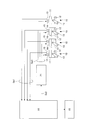
- FIG. 1 is a schematic configuration diagram illustrating an example of an embodiment of a knock determination device and a knock control device for an internal combustion engine according to the present invention.
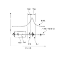
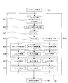
- FIG. 2 is a block diagram for explaining an example (first embodiment) of knocking determination and control in the knocking determination device and knocking control device for the internal combustion engine shown in FIG. 1. It is a figure explaining the time window in the block diagram shown in FIG.
- FIG. 7 is a block diagram for explaining another example (Example 2) of knocking determination and control in the knocking determination device and the knocking control device of the internal combustion engine shown in FIG. 1.
- FIG. 8 is a block diagram for explaining another example (third embodiment) of knocking determination and control in the knocking determination device and knocking control device for the internal combustion engine shown in FIG. 1.
- FIG. 1 is a schematic configuration diagram illustrating a knock determination device and a knock control device for an internal combustion engine according to the present embodiment.
- 2 is a block diagram illustrating knocking determination and control in the knocking determination device and knocking control device of the internal combustion engine illustrated in FIG. 1, and
- FIG. 3 illustrates a time window in the block diagram illustrated in FIG. It is a figure to do.
- the internal combustion engine has at least one cylinder 10 as shown in FIG. 1 (in FIG. 1, four cylinders 10 are shown as an example). And an ECU (Electronics Control Unit) 20 that performs determination and control by arithmetic processing described later, and an ignition device 21 that controls a spark plug 14 described later based on a command from the ECU 20.
- the alarm device 22 will be described in a fourth embodiment described later.
- Each cylinder 10 includes a cylinder 11, a piston 12 that reciprocates within the cylinder 11, and a crank 13 that is coupled to the piston 12, and a crankshaft (not shown) is rotationally driven via the crank 13. Is done. Further, the cylinder 11 also has an air supply valve and an air supply port for supplying air together with fuel made of gas, gasoline, and the like, an exhaust valve and an exhaust port for exhausting the combusted fuel from the cylinder 11, but in FIG. The illustration is omitted.
- the fuel supplied to the cylinder 11 is ignited and burned using a spark plug 14 attached to the cylinder 11.
- a knock sensor 15 attached to the cylinder 11 a physical quantity correlated with the knocking intensity generated in each cylinder 10 is detected as the knock sensor signal Sg1.
- an acceleration sensor that detects acceleration is used as the knock sensor 15.
- an in-cylinder pressure sensor that detects in-cylinder pressure may be used. It can be implemented.
- the knock sensor signal Sg1 of each cylinder 10 detected by the knock sensor 15 is input to the ECU 20, and using the input knock sensor signal Sg1, calculation processing described later is performed to perform knocking determination. Then, the ECU 20 transmits an ignition timing command Sg2 for each cylinder 10 to the ignition device 21 based on the knocking determination by the arithmetic processing, and the ignition device 21 sends an ignition signal Sg3 to each cylinder 10 based on the ignition timing command Sg2. Is sending.
- Each cylinder 10 shown in FIG. 1 is also provided with a crank angle sensor for detecting the crank angle of the crankshaft, and a signal from this sensor is also input to the ECU 20 and used for arithmetic processing described later. Yes.
- the internal combustion engine shown in FIG. 1 may be another internal combustion engine as long as it has a similar function.
- a gas engine, a gasoline engine, a diesel engine, or the like may be used.
- Block B1 When the knock sensor signal Sg1 of each cylinder 10 detected by the knock sensor 15 is input to the ECU 20, the knock sensor signal Sg1 is knocked using the knocking time window TW1 (see FIG. 3) in the time zone where knocking occurs. Cut out the data.
- the knocking time window TW1 a crank angle range may be defined in advance.
- the knocking time window TW1 is from the crank angle after ignition and before the peak of the in-cylinder pressure to the crank angle at which combustion ends.
- Block B2 The extracted knocking data is passed through a BPF that allows only the knocking frequency component to pass, and a waveform signal having a knocking frequency (for example, about 3 kHz) is extracted.
- a knocking frequency for example, about 3 kHz
- Block B3 A calculation process of the waveform signal of the extracted knocking frequency is performed to obtain a first calculation value. For example, calculation processing for obtaining an integral value of the absolute value of the waveform signal and obtaining a value equivalent to POA is performed. Instead of this arithmetic processing, arithmetic processing for obtaining the maximum value of amplitude may be performed, or arithmetic processing for obtaining POA by performing FFT analysis may be performed.
- the integral value and the POA are mathematically equivalent.
- the power spectrum is calculated by the FFT analysis, the power spectrum density is calculated based on the calculated power spectrum, and the sum of squares of the power spectrum density near the knocking frequency is calculated. Thus, what is necessary is just to obtain
- Block B4 Similarly to the block B1 described above, reference data is cut out from the knock sensor signal Sg1 using the reference time window.
- reference time window and reference data will be described with reference to FIG.
- reference data data Dr1 when knocking has not occurred, data Dr2 at the early stage of combustion, or background data Dr3 when no ignition is performed can be used.
- FIG. 3 the in-cylinder pressure of the cylinder 11 is also shown for reference.
- the same time window as the knocking time window TW1 for detecting knocking is used, data below a prescribed value defined in advance is held, and this is used as reference data To do.
- the data to be held is sequentially updated and used as reference data.
- Block B5 As in the above-described block B2, the cut-out reference data is passed through a BPF that allows only the reference frequency component to pass, and a waveform signal of the reference frequency is extracted.
- a BPF that allows only a component having the same frequency as the knocking detection frequency (for example, about 3 kHz) may be used.
- the reference BPF is also different, and only the frequency component (for example, about 1 kHz) different from the knocking detection frequency is used. It is sufficient to use a BPF that passes through.
- the extracted reference frequency waveform signal is calculated to obtain a second calculation value, for example, the integral value or maximum amplitude value or POA of the absolute value of the waveform signal of the reference frequency. .
- Block B7 An average process of the second calculation values obtained by the calculation process of the block B6 is performed to obtain a reference average value.
- the reference average value may be obtained by moving average processing using the second calculated values of the most recent cycles, but for example, after passing through a low-pass filter for removing the upper limit value and the lower limit value.
- the reference average value may be obtained, or the standard deviation ( ⁇ ) of the second computed value in a plurality of cycles is obtained, and the reference average value is obtained for the second computed value within the obtained 1 ⁇ range. May be. It is necessary to determine the upper limit value and the lower limit value in advance, but when using the second calculation value within the range of 1 ⁇ , it is not necessary to determine the upper limit value and the lower limit value. Even if there is, the reference average value can be obtained by following the change with time.
- Block B8 The S / N ratio of the first calculation value is obtained by dividing the first calculation value obtained by the calculation process of the block B3 by the reference average value obtained by the average process of the block B7. Thereby, the individual difference of the sensor sensitivity of the knock sensor 15 can be corrected.
- Block B9 The relationship between the S / N ratio and the weighting factor is defined in advance, and the S / N ratio obtained in block B8 is weighted. That is, a multiplication value obtained by multiplying the obtained S / N ratio by the corresponding weight coefficient is obtained.
- the weighting coefficient is a coefficient that makes the calculated S / N ratio a numerical value that includes the knocking strength and the knocking frequency.
- the knocking determination can be performed only by evaluating one numerical value in one cycle. . Conventionally, knocking determination is performed from knocking strength and knocking frequency, and a predetermined number of cycles are necessary for the determination. However, by performing the above-described weighting, large knocking can be detected quickly and easily. it can.
- the relationship between the S / N ratio and the weighting factor is actually defined as map data by performing a test operation of the internal combustion engine. At this time, the relationship between the knocking severity indicating the damage to the internal combustion engine (for example, damage due to liner temperature, damage to the piston ring, gasket, etc.) and the advance of the ignition timing is set to be equal to S.
- the relationship between the / N ratio and the weighting factor is defined. For example, on the basis of the maximum S / N ratio that damages the engine after only one occurrence, a curve as shown in block B9 (for example, an nth-order curve), that is, as the S / N ratio increases.
- the relationship between the S / N ratio and the weighting factor is defined so that the weighting factor becomes larger.
- Block B10 A moving average value is obtained for the S / N ratio (multiplication value) weighted in block B9. For example, the moving average value for the most recent weighted S / N ratios is obtained.
- the moving average value obtained in block B10 is the knock index.
- Knocking determination is performed on the knock index in block B11 based on a predetermined knock determination threshold.
- the knock determination threshold varies depending on the specifications of the internal combustion engine, and is set according to the specifications, but is, for example, 20 to 50%.
- Block B13 Control is performed based on the knocking determination in block B13. For example, depending on the magnitude of the knock index, ignition timing command Sg2 is ignited that delays ignition timing by a small amount, delays it greatly (retards), lowers the output, or trips (stops) the engine. Transmit to device 21.
- FIG. 4 is a block diagram illustrating knock determination and control in the knock determination device and the knock control device of the internal combustion engine of the present embodiment.
- the knocking determination and control of the present embodiment will be described.
- the knocking determination device and the knocking control device for the internal combustion engine shown in FIG. 1 perform the knocking determination and control described below, but other devices can be used as long as they have the same functions. But it ’s okay. Further, the following knocking determination and control are performed for each cylinder and each cycle.
- knocking data is extracted from the knock sensor signal Sg1 using the knocking time window TW1 in the time zone where knocking occurs.
- the knocking time window TW1 may be the one described in the first embodiment (see FIG. 3).
- the extracted knocking data is passed through a BPF that allows only the knocking frequency component to pass, and a waveform signal having a knocking frequency (for example, about 3 kHz) is extracted.
- a knocking frequency for example, about 3 kHz
- each knock index that is, a large knock index, a medium knock index, and a small knock index is calculated using the following Equation 1 and Table 1.
- C1 is the number of cycles exceeding the threshold Th for a predefined POA
- C2 is the number of specified cycles
- a plurality of sets of thresholds Th for the large knock index, medium knock index, and small knock index and the number of specified cycles C2 corresponding to the threshold Th are defined.
- the threshold value Th and the specified cycle number C2 shown in Table 1 are examples, and can be changed as appropriate according to the characteristics of the internal combustion engine. However, the higher the threshold value Th, the smaller the specified cycle number C2. .
- the calculated large knock index, medium knock index, and small knock index are determined based on knock determination thresholds for the predetermined large knock index, medium knock index, and small knock index, and control is performed based on the determination. For example, in the case of a small knock determination, the ignition timing is delayed by a small amount, in the case of a medium knock determination, the ignition timing is greatly delayed (retarded), and in the case of a large knock determination, the output is reduced, or the engine
- the ignition timing command Sg2 for tripping (stopping) is transmitted to the ignition device 21.
- the knock determination threshold varies depending on the specifications of the internal combustion engine, and is set according to the specifications, but is, for example, 20 to 50%.
- Block B29 A moving average is obtained for the POA calculated in block B24. For example, a moving average is calculated for a plurality of recent POAs. By obtaining the POA moving average, the tendency of knocking can be grasped.
- the POA is divided into a large knock index, a medium knock index, and a small knock index, and when calculating each knock index, the number of cycles is changed for each knock index, so that the detection speed for each knock index is changed.
- the depth can be changed, so that a larger knock can be detected more quickly.
- FIG. 5 is a block diagram illustrating knocking determination and control in the knocking determination device and knocking control device for the internal combustion engine of the present embodiment.
- the knocking determination and control of the present embodiment will be described.
- the knocking determination device and the knocking control device for the internal combustion engine shown in FIG. 1 perform the knocking determination and control described below. But it ’s okay. Further, the following knocking determination and control are performed for each cylinder and each cycle.
- knocking data is extracted from the knock sensor signal Sg1 using the knocking time window TW1 in the time zone where knocking occurs.
- the knocking time window TW1 may be the one described in the first embodiment (see FIG. 3).
- the extracted knocking data is passed through a BPF that allows only the knocking frequency component to pass, and a waveform signal having a knocking frequency (for example, about 3 kHz) is extracted.
- the knocking BPF may be the same as that described in the first embodiment.
- Block B33 A calculation process of the waveform signal of the extracted knocking frequency is performed to obtain a first calculation value. For example, calculation processing for obtaining an integral value of the absolute value of the waveform signal and obtaining a value equivalent to POA is performed. Instead of this arithmetic processing, arithmetic processing for obtaining the maximum value of amplitude may be performed, or arithmetic processing for obtaining POA by performing FFT analysis may be performed.
- the integral value and the POA are mathematically equivalent.
- reference data is cut out from the knock sensor signal Sg1 using a reference time window.
- the reference time window and reference data may also be those described in the first embodiment (see FIG. 3).
- Block B35 Similarly to the block B32 described above, the cut-out reference data is passed through a BPF that allows only the reference frequency component to pass, and a waveform signal of the reference frequency is extracted.
- the reference BPF may also be the one described in the first embodiment.
- the extracted reference frequency waveform signal is calculated to obtain a second calculated value, for example, the integral value or the maximum amplitude value or POA of the absolute value of the waveform signal of the reference frequency. .
- Block B37 An average process of the second calculation values obtained by the calculation process of the block B36 is performed to obtain a reference average value.
- the reference average value may be obtained.
- Block B38 The S / N ratio of the first calculation value is obtained by dividing the first calculation value obtained by the calculation process of the block B33 by the reference average value obtained by the average process of the block B37. Thereby, the individual difference of the sensor sensitivity of the knock sensor 15 can be corrected.
- Each knock index that is, a large knock index, a medium knock index, and a small knock index is calculated with respect to the S / N ratio that has been subjected to the calculation processing, using Equation 1 and Table 1 above.
- the threshold value Th in Table 1 may be defined with respect to the S / N ratio.
- the calculated large knock index, medium knock index, and small knock index are determined based on knock determination thresholds for the predetermined large knock index, medium knock index, and small knock index, and control is performed based on the determination. For example, in the case of a small knock determination, the ignition timing is delayed by a small amount, in the case of a medium knock determination, the ignition timing is greatly delayed (retarded), and in the case of a large knock determination, the output is reduced, or the engine
- the ignition timing command Sg2 for tripping (stopping) is transmitted to the ignition device 21.
- the knock determination threshold varies depending on the specifications of the internal combustion engine, and is set according to the specifications, but is, for example, 20 to 50%.
- the speed of detection can be changed for each knock index by changing the prescribed number of cycles for each knock index.
- the larger the knock the faster it can be detected.
- Example 4 A knock determination device and a knock control device for an internal combustion engine according to this embodiment will be described with reference to FIG.
- the knocking determination device and the knocking control device for the internal combustion engine shown in FIG. 1 are illustrated, but other devices may be used as long as they have equivalent functions.
- the present embodiment further includes an alarm device 22 that issues and transmits an alarm based on a command from the ECU 20.
- the ECU 20 holds data of the initial stage of shipment of the internal combustion engine in advance for the second calculated value (the integrated value of the absolute value of the waveform signal of the reference frequency or the maximum value of the amplitude or POA) described in the first embodiment. This is set as a reference value. And if the 2nd calculated value of the arbitrary cylinders 10 acquired after that falls below a standard threshold defined beforehand with respect to a standard value, it will judge with a sensitivity fall by a secular change.
- the second calculation value of all the cylinders 10 may be averaged and used as a reference value. Also in this case, if the second calculated value of the arbitrary cylinder 10 acquired thereafter falls below the reference threshold value defined in advance with respect to the reference value, it is determined that the sensitivity is decreased due to secular change.
- two types of deterioration of the knock sensor 15 and deterioration of the cable can be detected as the secular change.
- the ECU 20 uses the alarm device 22 to notify the operator of the detection result of the decrease in sensitivity due to the secular change or to transmit to the remote monitoring device, thereby notifying the secular change and its precursor. ing.
- the present invention is applicable to internal combustion engines such as gas engines and gasoline engines.
Landscapes
- Engineering & Computer Science (AREA)
- Chemical & Material Sciences (AREA)
- Combustion & Propulsion (AREA)
- Mechanical Engineering (AREA)
- General Engineering & Computer Science (AREA)
- Signal Processing (AREA)
- Physics & Mathematics (AREA)
- General Physics & Mathematics (AREA)
- Computer Hardware Design (AREA)
- Microelectronics & Electronic Packaging (AREA)
- Combined Controls Of Internal Combustion Engines (AREA)
- Electrical Control Of Ignition Timing (AREA)
Priority Applications (3)
| Application Number | Priority Date | Filing Date | Title |
|---|---|---|---|
| EP14877895.4A EP3078841B1 (de) | 2014-01-10 | 2014-11-25 | Klopfbestimmungsvorrichtung und klopfsteuerungsvorrichtung für brennkraftmaschine |
| US15/110,722 US10082093B2 (en) | 2014-01-10 | 2014-11-25 | Knocking determination device and knocking control device for internal combustion engine |
| CN201480072758.4A CN105899792B (zh) | 2014-01-10 | 2014-11-25 | 内燃机的爆震判定装置及爆震控制装置 |
Applications Claiming Priority (2)
| Application Number | Priority Date | Filing Date | Title |
|---|---|---|---|
| JP2014002968A JP6288699B2 (ja) | 2014-01-10 | 2014-01-10 | 内燃機関のノッキング判定装置及びノッキング制御装置 |
| JP2014-002968 | 2014-01-10 |
Publications (1)
| Publication Number | Publication Date |
|---|---|
| WO2015104909A1 true WO2015104909A1 (ja) | 2015-07-16 |
Family
ID=53523749
Family Applications (1)
| Application Number | Title | Priority Date | Filing Date |
|---|---|---|---|
| PCT/JP2014/081002 WO2015104909A1 (ja) | 2014-01-10 | 2014-11-25 | 内燃機関のノッキング判定装置及びノッキング制御装置 |
Country Status (5)
| Country | Link |
|---|---|
| US (1) | US10082093B2 (de) |
| EP (1) | EP3078841B1 (de) |
| JP (1) | JP6288699B2 (de) |
| CN (1) | CN105899792B (de) |
| WO (1) | WO2015104909A1 (de) |
Cited By (2)
| Publication number | Priority date | Publication date | Assignee | Title |
|---|---|---|---|---|
| CN106762327A (zh) * | 2015-11-24 | 2017-05-31 | 联合汽车电子有限公司 | 发动机爆震检测方法及发动机早燃检测方法 |
| JP2017129101A (ja) * | 2016-01-22 | 2017-07-27 | 三菱重工業株式会社 | ノッキング検出方法、点火時期制御方法および内燃機関の制御システム |
Families Citing this family (15)
| Publication number | Priority date | Publication date | Assignee | Title |
|---|---|---|---|---|
| JP6049921B1 (ja) * | 2016-01-29 | 2016-12-21 | 川崎重工業株式会社 | ガスエンジンの制御方法およびガスエンジン駆動システム |
| JP6587981B2 (ja) * | 2016-06-06 | 2019-10-09 | 三菱重工エンジン&ターボチャージャ株式会社 | ノッキング検出方法及びノッキング検出装置 |
| WO2018044294A1 (en) * | 2016-08-31 | 2018-03-08 | General Electric Company | System and method for determining the timing of an engine event |
| DE102016216531A1 (de) * | 2016-09-01 | 2018-03-01 | Robert Bosch Gmbh | Verfahren zur Klopferkennung einer Brennkraftmaschine |
| KR102417381B1 (ko) * | 2016-12-14 | 2022-07-06 | 현대자동차주식회사 | 인젝션 분사 제어 장치 및 방법 |
| DE102017201801B4 (de) * | 2017-02-06 | 2019-09-05 | Robert Bosch Gmbh | Verfahren und Vorrichtung zur Regelung einer Verbrennung einer Brennkraftmaschine |
| CN108533413B (zh) * | 2017-03-01 | 2020-10-09 | 联合汽车电子有限公司 | 一种发动机早燃检测优化方法及系统 |
| CN106930845B (zh) * | 2017-04-12 | 2019-08-27 | 潍柴西港新能源动力有限公司 | 一种燃气发动机爆震标定方法 |
| US20200208587A1 (en) * | 2017-10-27 | 2020-07-02 | Mitsubishi Heavy Industries Engine & Turbocharger, Ltd. | Knocking detection method and knocking detection device |
| JP6848888B2 (ja) * | 2018-01-22 | 2021-03-24 | マツダ株式会社 | 強ノックの抑制が可能なエンジン |
| CN109406155A (zh) * | 2018-12-21 | 2019-03-01 | 中国人民解放军空军工程大学 | 基于振动信号的旋转爆震发动机状态监测装置及方法 |
| JP7402715B2 (ja) * | 2020-03-06 | 2023-12-21 | 東京エレクトロン株式会社 | ウエハを処理する方法 |
| CN111878279B (zh) * | 2020-06-29 | 2021-08-31 | 东风汽车集团有限公司 | 一种油品辛烷值自学习的方法及系统 |
| CN112127998B (zh) * | 2020-08-25 | 2022-04-26 | 潍柴动力股份有限公司 | 发动机爆震识别方法、系统及设备 |
| CN112922724B (zh) * | 2021-03-16 | 2022-04-15 | 东风汽车集团股份有限公司 | 一种爆震干扰的识别方法 |
Citations (6)
| Publication number | Priority date | Publication date | Assignee | Title |
|---|---|---|---|---|
| JPH0914043A (ja) * | 1995-07-03 | 1997-01-14 | Hitachi Ltd | ノッキング検出装置 |
| JP2001234804A (ja) * | 2000-02-25 | 2001-08-31 | Daihatsu Motor Co Ltd | イオン電流による内燃機関のノック検出方法 |
| JP2007231903A (ja) | 2006-03-03 | 2007-09-13 | Yanmar Co Ltd | 内燃機関のノッキング判定装置 |
| JP4919097B2 (ja) | 2008-05-30 | 2012-04-18 | 株式会社デンソー | 内燃機関のノック判定装置 |
| JP2012103157A (ja) * | 2010-11-11 | 2012-05-31 | A & D Co Ltd | ノッキング判定方法及び装置 |
| JP2013204496A (ja) * | 2012-03-28 | 2013-10-07 | Suzuki Motor Corp | ノック検出方法および装置 |
Family Cites Families (13)
| Publication number | Priority date | Publication date | Assignee | Title |
|---|---|---|---|---|
| DE69017063T2 (de) * | 1989-04-14 | 1995-09-21 | Hitachi Ltd | Motorüberwacher, ausgerüstet mit Klopfdetektor. |
| JP3668497B2 (ja) * | 1992-09-30 | 2005-07-06 | 株式会社日立製作所 | 内燃機関のノッキング検出方法及び点火時期制御方法 |
| EP0709662B1 (de) | 1994-10-31 | 1999-05-06 | Motorola, Inc. | Klopferkennungssystem |
| JP2006226967A (ja) * | 2005-02-21 | 2006-08-31 | Toyota Motor Corp | 内燃機関のノッキング判定装置 |
| JP4397346B2 (ja) * | 2005-04-26 | 2010-01-13 | トヨタ自動車株式会社 | 内燃機関のノッキング判定装置 |
| JP4549920B2 (ja) * | 2005-04-27 | 2010-09-22 | トヨタ自動車株式会社 | 内燃機関のノッキング判定装置 |
| JP4404811B2 (ja) * | 2005-06-28 | 2010-01-27 | トヨタ自動車株式会社 | ノッキング状態判定装置 |
| JP4357501B2 (ja) * | 2006-05-29 | 2009-11-04 | トヨタ自動車株式会社 | 内燃機関のノッキング判定装置 |
| JP4827936B2 (ja) * | 2008-03-18 | 2011-11-30 | 本田技研工業株式会社 | 内燃機関のノッキング検出装置 |
| EP2180178B1 (de) * | 2008-10-21 | 2014-03-12 | Magneti Marelli S.p.A. | Verfahren zum Bestimmen der klopfenden Verbrennung einer Brennkraftmaschine |
| JP5234143B2 (ja) * | 2011-06-28 | 2013-07-10 | トヨタ自動車株式会社 | 内燃機関の診断装置 |
| CN102735395A (zh) * | 2012-06-21 | 2012-10-17 | 天津大学 | 一种内燃机爆震在线诊断和控制方法 |
| JP6059194B2 (ja) * | 2014-11-04 | 2017-01-11 | トヨタ自動車株式会社 | 内燃機関のノック判定装置 |
-
2014
- 2014-01-10 JP JP2014002968A patent/JP6288699B2/ja active Active
- 2014-11-25 CN CN201480072758.4A patent/CN105899792B/zh active Active
- 2014-11-25 EP EP14877895.4A patent/EP3078841B1/de active Active
- 2014-11-25 US US15/110,722 patent/US10082093B2/en active Active
- 2014-11-25 WO PCT/JP2014/081002 patent/WO2015104909A1/ja active Application Filing
Patent Citations (6)
| Publication number | Priority date | Publication date | Assignee | Title |
|---|---|---|---|---|
| JPH0914043A (ja) * | 1995-07-03 | 1997-01-14 | Hitachi Ltd | ノッキング検出装置 |
| JP2001234804A (ja) * | 2000-02-25 | 2001-08-31 | Daihatsu Motor Co Ltd | イオン電流による内燃機関のノック検出方法 |
| JP2007231903A (ja) | 2006-03-03 | 2007-09-13 | Yanmar Co Ltd | 内燃機関のノッキング判定装置 |
| JP4919097B2 (ja) | 2008-05-30 | 2012-04-18 | 株式会社デンソー | 内燃機関のノック判定装置 |
| JP2012103157A (ja) * | 2010-11-11 | 2012-05-31 | A & D Co Ltd | ノッキング判定方法及び装置 |
| JP2013204496A (ja) * | 2012-03-28 | 2013-10-07 | Suzuki Motor Corp | ノック検出方法および装置 |
Cited By (6)
| Publication number | Priority date | Publication date | Assignee | Title |
|---|---|---|---|---|
| CN106762327A (zh) * | 2015-11-24 | 2017-05-31 | 联合汽车电子有限公司 | 发动机爆震检测方法及发动机早燃检测方法 |
| JP2017129101A (ja) * | 2016-01-22 | 2017-07-27 | 三菱重工業株式会社 | ノッキング検出方法、点火時期制御方法および内燃機関の制御システム |
| WO2017126304A1 (ja) * | 2016-01-22 | 2017-07-27 | 三菱重工業株式会社 | ノッキング検出方法、点火時期制御方法および点火時期制御システム |
| CN108474317A (zh) * | 2016-01-22 | 2018-08-31 | 三菱重工业株式会社 | 爆震检测方法、点火正时控制方法以及点火正时控制系统 |
| EP3392493A4 (de) * | 2016-01-22 | 2019-01-16 | Mitsubishi Heavy Industries, Ltd. | Klopferkennungsverfahren, verfahren zur steuerung der zündungsdauer und system zur steuerung der zündungsdauer |
| US10865719B2 (en) | 2016-01-22 | 2020-12-15 | Mitsubishi Heavy Industries, Ltd. | Knocking detection method, ignition timing control method, and ignition timing control system |
Also Published As
| Publication number | Publication date |
|---|---|
| EP3078841A4 (de) | 2017-01-25 |
| US20160333806A1 (en) | 2016-11-17 |
| EP3078841B1 (de) | 2018-04-11 |
| JP6288699B2 (ja) | 2018-03-07 |
| CN105899792A (zh) | 2016-08-24 |
| CN105899792B (zh) | 2019-04-26 |
| EP3078841A1 (de) | 2016-10-12 |
| JP2015132185A (ja) | 2015-07-23 |
| US10082093B2 (en) | 2018-09-25 |
Similar Documents
| Publication | Publication Date | Title |
|---|---|---|
| JP6288699B2 (ja) | 内燃機関のノッキング判定装置及びノッキング制御装置 | |
| JP4311657B2 (ja) | 内燃機関のノック検出装置 | |
| US8316824B2 (en) | Control apparatus for internal combustion engine | |
| RU2009149320A (ru) | Устройство определения детонации и способ определения детонации для двигателя внутреннего сгорания | |
| JP6257158B2 (ja) | オットー機関における過早着火を識別するための方法及び装置 | |
| EP2927467B1 (de) | Gas- oder Zweibrennstoffmaschine | |
| AU2011207854B2 (en) | Device and method for analysing a performance of an engine | |
| EP2843218A2 (de) | Positionsbasierte Berechnung des Luft/Kraftstoff-Verhältnisses in einem Verbrennungsmotor | |
| RU2017123182A (ru) | Способ и система управления регенерацией фильтра твердых частиц | |
| EP3371436A1 (de) | Motorsteuerungsverfahren und motorsteuerungsvorrichtung | |
| JP2007231903A (ja) | 内燃機関のノッキング判定装置 | |
| CN103306837A (zh) | 用于阻止燃料空气混合物在内燃机气缸室中预燃的方法 | |
| CN105571871B (zh) | 一种在线诊断柴油机工作不均匀性的方法 | |
| Galloni | Knock-limited spark angle setting by means of statistical or dynamic pressure based methods | |
| US10060376B2 (en) | Method and device for detecting auto-ignitions in a spark ignition internal combustion engine | |
| JP5278053B2 (ja) | エンジンの制御装置 | |
| JP5708543B2 (ja) | 内燃機関の制御装置 | |
| CN104169549B (zh) | 用于控制爆震的方法和装置 | |
| JP2017218936A (ja) | ノッキング検出方法及びノッキング検出装置 | |
| WO2015033371A1 (ja) | エンジンの異常燃焼検出装置及びエンジンの異常燃焼検出方法 | |
| US20200208587A1 (en) | Knocking detection method and knocking detection device | |
| JP2008240627A (ja) | エンジンのノッキング判定装置 | |
| Lezius et al. | Improvements in knock control | |
| JP6244878B2 (ja) | ディーゼルエンジンの燃焼状態の検出装置及び検出方法 | |
| RU2011117415A (ru) | Способ определения остаточного ресурса цилиндропоршневой группы двигателя внутреннего сгорания |
Legal Events
| Date | Code | Title | Description |
|---|---|---|---|
| 121 | Ep: the epo has been informed by wipo that ep was designated in this application |
Ref document number: 14877895 Country of ref document: EP Kind code of ref document: A1 |
|
| REEP | Request for entry into the european phase |
Ref document number: 2014877895 Country of ref document: EP |
|
| WWE | Wipo information: entry into national phase |
Ref document number: 2014877895 Country of ref document: EP |
|
| WWE | Wipo information: entry into national phase |
Ref document number: 15110722 Country of ref document: US |
|
| NENP | Non-entry into the national phase |
Ref country code: DE |