EP3078841A1 - Klopfbestimmungsvorrichtung und klopfsteuerungsvorrichtung für brennkraftmaschine - Google Patents
Klopfbestimmungsvorrichtung und klopfsteuerungsvorrichtung für brennkraftmaschine Download PDFInfo
- Publication number
- EP3078841A1 EP3078841A1 EP14877895.4A EP14877895A EP3078841A1 EP 3078841 A1 EP3078841 A1 EP 3078841A1 EP 14877895 A EP14877895 A EP 14877895A EP 3078841 A1 EP3078841 A1 EP 3078841A1
- Authority
- EP
- European Patent Office
- Prior art keywords
- knocking
- internal combustion
- combustion engine
- value
- determination device
- Prior art date
- Legal status (The legal status is an assumption and is not a legal conclusion. Google has not performed a legal analysis and makes no representation as to the accuracy of the status listed.)
- Granted
Links
- 238000002485 combustion reaction Methods 0.000 title claims abstract description 78
- 230000001133 acceleration Effects 0.000 claims description 14
- 239000000284 extract Substances 0.000 claims description 13
- 230000035945 sensitivity Effects 0.000 claims description 11
- 230000007423 decrease Effects 0.000 claims description 6
- 230000003247 decreasing effect Effects 0.000 claims description 6
- 230000002596 correlated effect Effects 0.000 claims description 3
- 230000010354 integration Effects 0.000 abstract description 11
- 238000000034 method Methods 0.000 description 39
- 238000010586 diagram Methods 0.000 description 12
- 230000032683 aging Effects 0.000 description 10
- 238000001514 detection method Methods 0.000 description 8
- 230000000875 corresponding effect Effects 0.000 description 6
- 238000012935 Averaging Methods 0.000 description 5
- 239000000446 fuel Substances 0.000 description 4
- 230000003595 spectral effect Effects 0.000 description 3
- 238000007796 conventional method Methods 0.000 description 2
- 238000001228 spectrum Methods 0.000 description 2
- 230000006866 deterioration Effects 0.000 description 1
- 230000000694 effects Effects 0.000 description 1
- 238000012806 monitoring device Methods 0.000 description 1
- 238000012360 testing method Methods 0.000 description 1
Images


Classifications
-
- F—MECHANICAL ENGINEERING; LIGHTING; HEATING; WEAPONS; BLASTING
- F02—COMBUSTION ENGINES; HOT-GAS OR COMBUSTION-PRODUCT ENGINE PLANTS
- F02D—CONTROLLING COMBUSTION ENGINES
- F02D35/00—Controlling engines, dependent on conditions exterior or interior to engines, not otherwise provided for
- F02D35/02—Controlling engines, dependent on conditions exterior or interior to engines, not otherwise provided for on interior conditions
- F02D35/027—Controlling engines, dependent on conditions exterior or interior to engines, not otherwise provided for on interior conditions using knock sensors
-
- F—MECHANICAL ENGINEERING; LIGHTING; HEATING; WEAPONS; BLASTING
- F02—COMBUSTION ENGINES; HOT-GAS OR COMBUSTION-PRODUCT ENGINE PLANTS
- F02D—CONTROLLING COMBUSTION ENGINES
- F02D35/00—Controlling engines, dependent on conditions exterior or interior to engines, not otherwise provided for
- F02D35/02—Controlling engines, dependent on conditions exterior or interior to engines, not otherwise provided for on interior conditions
- F02D35/023—Controlling engines, dependent on conditions exterior or interior to engines, not otherwise provided for on interior conditions by determining the cylinder pressure
-
- F—MECHANICAL ENGINEERING; LIGHTING; HEATING; WEAPONS; BLASTING
- F02—COMBUSTION ENGINES; HOT-GAS OR COMBUSTION-PRODUCT ENGINE PLANTS
- F02D—CONTROLLING COMBUSTION ENGINES
- F02D41/00—Electrical control of supply of combustible mixture or its constituents
- F02D41/02—Circuit arrangements for generating control signals
- F02D41/04—Introducing corrections for particular operating conditions
- F02D41/042—Introducing corrections for particular operating conditions for stopping the engine
-
- F—MECHANICAL ENGINEERING; LIGHTING; HEATING; WEAPONS; BLASTING
- F02—COMBUSTION ENGINES; HOT-GAS OR COMBUSTION-PRODUCT ENGINE PLANTS
- F02D—CONTROLLING COMBUSTION ENGINES
- F02D41/00—Electrical control of supply of combustible mixture or its constituents
- F02D41/02—Circuit arrangements for generating control signals
- F02D41/04—Introducing corrections for particular operating conditions
- F02D41/12—Introducing corrections for particular operating conditions for deceleration
-
- F—MECHANICAL ENGINEERING; LIGHTING; HEATING; WEAPONS; BLASTING
- F02—COMBUSTION ENGINES; HOT-GAS OR COMBUSTION-PRODUCT ENGINE PLANTS
- F02D—CONTROLLING COMBUSTION ENGINES
- F02D41/00—Electrical control of supply of combustible mixture or its constituents
- F02D41/22—Safety or indicating devices for abnormal conditions
-
- F—MECHANICAL ENGINEERING; LIGHTING; HEATING; WEAPONS; BLASTING
- F02—COMBUSTION ENGINES; HOT-GAS OR COMBUSTION-PRODUCT ENGINE PLANTS
- F02D—CONTROLLING COMBUSTION ENGINES
- F02D41/00—Electrical control of supply of combustible mixture or its constituents
- F02D41/24—Electrical control of supply of combustible mixture or its constituents characterised by the use of digital means
- F02D41/26—Electrical control of supply of combustible mixture or its constituents characterised by the use of digital means using computer, e.g. microprocessor
-
- F—MECHANICAL ENGINEERING; LIGHTING; HEATING; WEAPONS; BLASTING
- F02—COMBUSTION ENGINES; HOT-GAS OR COMBUSTION-PRODUCT ENGINE PLANTS
- F02P—IGNITION, OTHER THAN COMPRESSION IGNITION, FOR INTERNAL-COMBUSTION ENGINES; TESTING OF IGNITION TIMING IN COMPRESSION-IGNITION ENGINES
- F02P5/00—Advancing or retarding ignition; Control therefor
- F02P5/04—Advancing or retarding ignition; Control therefor automatically, as a function of the working conditions of the engine or vehicle or of the atmospheric conditions
- F02P5/145—Advancing or retarding ignition; Control therefor automatically, as a function of the working conditions of the engine or vehicle or of the atmospheric conditions using electrical means
- F02P5/15—Digital data processing
- F02P5/152—Digital data processing dependent on pinking
-
- G—PHYSICS
- G01—MEASURING; TESTING
- G01L—MEASURING FORCE, STRESS, TORQUE, WORK, MECHANICAL POWER, MECHANICAL EFFICIENCY, OR FLUID PRESSURE
- G01L23/00—Devices or apparatus for measuring or indicating or recording rapid changes, such as oscillations, in the pressure of steam, gas, or liquid; Indicators for determining work or energy of steam, internal-combustion, or other fluid-pressure engines from the condition of the working fluid
- G01L23/22—Devices or apparatus for measuring or indicating or recording rapid changes, such as oscillations, in the pressure of steam, gas, or liquid; Indicators for determining work or energy of steam, internal-combustion, or other fluid-pressure engines from the condition of the working fluid for detecting or indicating knocks in internal-combustion engines; Units comprising pressure-sensitive members combined with ignitors for firing internal-combustion engines
- G01L23/221—Devices or apparatus for measuring or indicating or recording rapid changes, such as oscillations, in the pressure of steam, gas, or liquid; Indicators for determining work or energy of steam, internal-combustion, or other fluid-pressure engines from the condition of the working fluid for detecting or indicating knocks in internal-combustion engines; Units comprising pressure-sensitive members combined with ignitors for firing internal-combustion engines for detecting or indicating knocks in internal combustion engines
-
- F—MECHANICAL ENGINEERING; LIGHTING; HEATING; WEAPONS; BLASTING
- F02—COMBUSTION ENGINES; HOT-GAS OR COMBUSTION-PRODUCT ENGINE PLANTS
- F02D—CONTROLLING COMBUSTION ENGINES
- F02D41/00—Electrical control of supply of combustible mixture or its constituents
- F02D41/02—Circuit arrangements for generating control signals
- F02D41/14—Introducing closed-loop corrections
- F02D41/1401—Introducing closed-loop corrections characterised by the control or regulation method
- F02D2041/1413—Controller structures or design
- F02D2041/1432—Controller structures or design the system including a filter, e.g. a low pass or high pass filter
-
- Y—GENERAL TAGGING OF NEW TECHNOLOGICAL DEVELOPMENTS; GENERAL TAGGING OF CROSS-SECTIONAL TECHNOLOGIES SPANNING OVER SEVERAL SECTIONS OF THE IPC; TECHNICAL SUBJECTS COVERED BY FORMER USPC CROSS-REFERENCE ART COLLECTIONS [XRACs] AND DIGESTS
- Y02—TECHNOLOGIES OR APPLICATIONS FOR MITIGATION OR ADAPTATION AGAINST CLIMATE CHANGE
- Y02T—CLIMATE CHANGE MITIGATION TECHNOLOGIES RELATED TO TRANSPORTATION
- Y02T10/00—Road transport of goods or passengers
- Y02T10/10—Internal combustion engine [ICE] based vehicles
- Y02T10/40—Engine management systems
Definitions
- the present invention relates to a knocking determination device and knocking control device for an internal combustion engine configured to perform knocking determination and control for a gas engine, a petrol engine, or the like.
- knocking occurs, in which fuel combusts abnormally inside cylinders. If the intensity of the knocking is high, the engines may possibly be damaged. Thus, these engines detect knocking and control the ignition timing or perform control to lower the output in accordance with the knocking intensity.
- Knocking determination is done by using an in-cylinder pressure sensor or by using, for example, an acceleration sensor or the like. Generally, the following method is used for the knocking determination.
- Knocking does not hold the same intensity over consecutive cycles. In conditions where knocking is prone to occur, the average of the knock index tends to increase and the knock index tends to be frequently large. Also, in a case where the knocking intensity is high, an ability to quickly detect the knocking is required to prevent the knocking from damaging the engine.
- knocking determination needs to be done with the following points taken into consideration:
- the present invention has been made in view of the above problems, and an object thereof is to provide a knocking determination device and a knocking control device for an internal combustion engine capable of quickly detecting large knocking and easily performing knocking determination.
- a knocking determination device for an internal combustion engine for solving the above problems is a knocking determination device for an internal combustion engine comprising:
- a knocking determination device for an internal combustion engine according to a second aspect of the invention for solving the above problems is the knocking determination device for an internal combustion engine according to the first aspect of the invention in which the control means defines in advance a weighting coefficient with which to convert the ratio into the knock index, and obtains a product by multiplying the ratio by the weighting coefficient, obtains a moving average of a plurality of the products, and uses the moving average as the knock index for performing the knocking determination.
- a knocking determination device for an internal combustion engine according to a third aspect of the invention for solving the above problems is the knocking determination device for an internal combustion engine according to the second aspect of the invention in which the control means increases the weighting coefficient as the ratio increases.
- a knocking determination device for an internal combustion engine according to a fourth aspect of the invention for solving the above problems is the knocking determination device for an internal combustion engine according to the first aspect of the invention in which the control means defines in advance a threshold for the ratio and a predefined number of times depending on the threshold, obtains a percentage by dividing the number of times the ratio exceeds the threshold by the predefined number of times, and uses the percentage as the knock index for performing the knocking determination.
- a knocking determination device for an internal combustion engine according to a fifth aspect of the invention for solving the above problems is the knocking determination device for an internal combustion engine according to the fourth aspect of the invention in which the control means defines a plurality of sets of the threshold and the predefined number of times depending on the threshold, the threshold and the predefined number of times differing between the plurality of sets such that the predefined number of times decreases as the threshold increases.
- a knocking determination device for an internal combustion engine for solving the above problems is the knocking determination device for an internal combustion engine according to any one of the first to fifth aspects of the invention in which the control means extracts the knocking-frequency waveform signal and the reference-frequency waveform signal from a same time period in the sensor signal, and sets a signal not greater than a predefined value as the reference-frequency waveform signal.
- a knocking determination device for an internal combustion engine according to a seventh aspect of the invention for solving the above problems is the knocking determination device for an internal combustion engine according to any one of the first to fifth aspects of the invention in which the control means extracts the knocking-frequency waveform signal and the reference-frequency waveform signal from mutually different time periods in the sensor signal, and sets the time period for the reference-frequency waveform signal to any one of a time period immediately before the time period for the knocking-frequency waveform signal and a time period at the time of non-ignition.
- a knocking determination device for an internal combustion engine according to an eighth aspect of the invention for solving the above problems is the knocking determination device for an internal combustion engine according to any one of the first to seventh aspects of the invention in which the control means obtains a standard deviation for a plurality of the second computation values, and obtains the average by using the second computation values within a range of the standard deviation.
- a knocking determination device for an internal combustion engine according to a ninth aspect of the invention for solving the above problems is the knocking determination device for an internal combustion engine according to any one of the first to eighth aspects of the invention in which the control means holds the second computation value obtained from the internal combustion engine in an initial state as a reference value and defines a reference threshold for the reference value, and determines and notifies that sensitivity of the acceleration sensor or the in-cylinder pressure sensor has decreased, in a case where the second computation value newly computed falls beyond the reference threshold from the reference value.
- a knocking determination device for an internal combustion engine according to a tenth aspect of the invention for solving the above problems is the knocking determination device for an internal combustion engine according to any one of the first to eighth aspects of the invention in which the control means holds an average of the second computation values on all the cylinder units as a reference value and defines a reference threshold for the reference value, and determines and notifies that sensitivity of the acceleration sensor or the in-cylinder pressure sensor has decreased, in a case where the second computation value newly computed falls beyond the reference threshold from the reference value.
- a knocking control device for an internal combustion engine according to an eleventh aspect of the invention for solving the above problems is a knocking control device for an internal combustion engine using the knocking determination device for an internal combustion engine according to any one of the first to tenth aspects of the invention, wherein the control means retards ignition timings of the cylinder units, lowers output of the internal combustion engine, or stops the internal combustion engine in accordance with the knocking determination.
- a knock index including the knocking intensity and the knocking occurrence frequency is used.
- knocking determination can be performed easily, and the larger the knocking, the quicker it can be detected.
- sensitivity decrease due to aging can be detected as well.
- Fig. 1 is a schematic configuration diagram explaining a knocking determination device and a knocking control device for an internal combustion engine in this embodiment.
- Fig. 2 is a block diagram explaining knocking determination and control by the knocking determination device and the knocking control device for an internal combustion engine shown in Fig. 1
- Fig. 3 is a diagram explaining time windows in the block diagram shown in Fig. 2 .
- an internal combustion engine includes at least one cylinder unit 10 (four cylinder units 10 are exemplarily shown in Fig. 1 ), an ECU (Electronics Control Unit) 20 configured to perform determination and control by means of computation processes to be described later, and an ignition unit 21 configured to control spark plugs 14 to be described later based on instructions from the ECU 20.
- ECU Electronics Control Unit
- an ignition unit 21 configured to control spark plugs 14 to be described later based on instructions from the ECU 20.
- a warning unit 22 will be described in Embodiment 4 to be described later.
- Each cylinder unit 10 includes a cylinder 11, a piston 12 configured to reciprocate inside the cylinder 11, and a crank 13 connected to the piston 12, and a crankshaft (not shown) is rotationally driven through the crank 13.
- the cylinder unit 10 further includes an intake valve and an intake port through which to feed air into the cylinder 11 along with fuel made of gas, petrol, or the like, an exhaust valve and an exhaust port through which to discharge the fuel out of the cylinder 11 after its combustion, and the like, but they are not shown in Fig. 1 .
- the fuel fed into each cylinder 11 is combusted by igniting it using the spark plug 14 mounted to the cylinder 11. In doing so, a physical quantity correlated to the intensity of knocking occurring in each cylinder unit 10 is detected as a knock sensor signal Sg1 by using a knock sensor 15 mounted to the corresponding cylinder 11.
- an acceleration sensor configured to detect acceleration is used as the knock sensor 15.
- this embodiment and Embodiments 2 to 4 to be described later can be carried out by using an in-cylinder pressure sensor configured to detect in-cylinder pressure, instead of the acceleration sensor.
- the knock sensor signal Sg1 from each cylinder unit 10, detected by the corresponding knock sensor 15, is inputted into the ECU 20.
- the ECU 20 uses the inputted knock sensor signal Sg1, the ECU 20 performs later-described computation processes to perform knocking determination. Then, based on the knocking determination by the computation processes, the ECU 20 transmits an ignition timing instruction Sg2 for each cylinder unit 10 to the ignition unit 21. Based on the ignition timing instruction Sg2, the ignition unit 21 in turn transmits an ignition signal Sg3 to each cylinder unit 10.
- each cylinder unit 10, shown in Fig. 1 is also provided with a crank angle sensor configured to detect the crank angle of the crankshaft, and a signal from this sensor is also inputted into the ECU 20 and used in later-described computation processes.
- the internal combustion engine shown in Fig. 1 may be a different internal combustion engine as long as its configuration has equivalent functions.
- it may be a gas engine, a petrol engine, a diesel engine, or the like.
- the ECU 20 extracts knocking data from the knock sensor signal Sg1 by using a knocking time window TW1 (see Fig. 3 ) as a time period in which knocking occurs.
- the knocking time window TW1 may be a predefined range of crank angles.
- the knocking time window TW1 is from a crank angle after ignition but before the peak of the in-cylinder pressure to a crank angle at the end of combustion.
- the ECU 20 passes the extracted knocking data through a BPF configured to pass only knocking-frequency components, to extract a knocking-frequency (e.g. about 3 kHz) waveform signal.
- a BPF configured to pass only knocking-frequency components, to extract a knocking-frequency (e.g. about 3 kHz) waveform signal.
- the ECU 20 performs a computation process on the extracted knocking-frequency waveform signal to obtain a first computation value. For example, the ECU 20 performs a computation process of obtaining the integration value of the absolute value of the waveform signal to obtain a value equivalent to a POA. Note that, instead of this computation process, the ECU 20 may perform a computation process of obtaining the greatest value of amplitude of the waveform signal or a computation process of performing an FFT analysis on the waveform signal and obtaining a POA thereof.
- the integration value and the POA mentioned above are mathematically equivalent.
- the ECU 20 may obtain the POA by calculating a power spectrum with the FFT analysis, calculating power spectral densities based on the calculated power spectrum, and calculating the sum of squares of the power spectral densities around the knocking frequencies.
- the ECU 20 extracts reference data from the knock sensor signal Sg1 by using a reference time window.
- Fig. 3 shows the reference time window and the reference data.
- data Dr1 at the time of non-knocking, data Dr2 at an initial stage of combustion, or data Dr3 of a background at the time of non-ignition can be used.
- Fig. 3 also shows the in-cylinder pressure at the cylinder 11 for reference.
- data not greater than a prescribed value is held using the same time window as the knocking time window TW1 for knocking detection, and this data is used as the reference data. Whenever new data not greater than the prescribed value is acquired, the held data is updated thereto, and this updated data is used as the reference data.
- the ECU 20 passes the extracted reference data through a BPF configured to pass only reference-frequency components, to extract a reference-frequency waveform signal.
- the ECU 20 may use a BPF configured to pass only components of the same frequencies as the knocking detection frequencies (e.g. about 3 kHz).
- the time window for the reference data is different from the time window for the knocking data, i.e. the time window TW2 or TW3 is used, the reference BPF is likewise different; in this case, the ECU 20 may use a BPF configured to pass only components of frequencies different from the knocking detection frequencies (e.g. about 1kHz).
- the ECU 20 performs a computation process on the extracted reference-frequency waveform signal to obtain a second computation value. For example, the ECU 20 obtains the integration value of the absolute value of the reference-frequency waveform signal, the greatest value of amplitude thereof, or a POA thereof.
- the ECU 20 performs an averaging process on the second computation value obtained by the computation process in Block B6 to obtain a reference average.
- the ECU 20 may obtain the reference average by performing a moving average process using the second computation values from a plurality of cycles including the current cycle and one or more last cycles.
- the ECU 20 may pass the second computation values through a low-pass filter for removing upper and lower limit values, and then obtain the reference average therefrom.
- the ECU 20 may obtain a standard deviation ( ⁇ ) for the second computation values from a plurality of cycles and obtain the reference average from the second computation values within the range of 1 ⁇ thus obtained.
- the ECU 20 divides the first computation value, obtained by the computation process in Block B3, by the reference average, obtained by the averaging process in Block B7, to obtain the S/N ratio of the first computation value. In this way, the individual difference in sensor sensitivity between the knock sensors 15 can be corrected.
- the ECU 20 defines an S/N ratio - weighting coefficient correlation in advance and weights the S/N ratio obtained in Block B8. Specifically, the ECU 20 obtains a product by multiplying the obtained S/N ratio by a corresponding weighting coefficient.
- This weighting coefficient is a coefficient that converts the obtained S/N ratio into a numerical value including the knocking intensity and also the knocking occurrence frequency. This makes it possible to perform knocking determination only by evaluating a single numerical value at a single cycle. In conventional method, knocking determination is performed based on the knocking intensity and the knocking occurrence frequency, and a certain number of cycles are necessary for the determination. However, by using the weighting mentioned above, large knocking can be detected quickly and easily.
- the S/N ratio - weighting coefficient correlation is defined as map data by performing test operation of the internal combustion engine.
- the S/N ratio - weighting coefficient correlation is defined to be equivalent to the correlation between knocking severity, indicating damage to the internal combustion engine (e.g. damage by the liner temperature, damage to the piston ring and gasket, etc.) and advancement of the ignition timing.
- the S/N ratio - weighting coefficient correlation is defined as a curve as shown in Block B9 (e.g. an n-th order curve), that is, the larger the S/N ratio, the larger the weighting coefficient.
- the ECU 20 obtains a moving average for the S/N ratio weighted (product) in Block B9. For example, the ECU 20 obtains a moving average of a plurality of weighted S/N ratios including the current S/N ratio and one or more last S/N ratios.
- the moving average obtained in Block B10 serves as a knock index.
- the ECU 20 performs knocking determination on the knock index in Block B11 based on a predefined knock determination threshold.
- the knock determination threshold varies depending on the specification of the internal combustion engine and is therefore set in accordance with the specification. However, the knock determination threshold is 20 to 50%, for example.
- the ECU 20 performs control based on the knocking determination in Block B13. For example, the ECU 20 transmits an ignition timing instruction Sg2 to the ignition unit 21 to delay (retard) the ignition timing by a short or long period of time or even lower the output or trip (stop) the engine in accordance with the magnitude of the knock index.
- Using a weighted knock index as described above can provide a numerical value including the knocking intensity and also the knocking occurrence frequency. Thus, it is possible to handle small to large knocking with a single analog value. In this way, the knocking determination can be easier and the control can be easier, and also large knocking can be detected quickly.
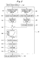
- Fig. 4 is a block diagram explaining knocking determination and control by a knocking determination device and a knocking control device for an internal combustion engine in this embodiment.
- the knocking determination and the control in this embodiment will be described with reference to Fig. 4 .
- the knocking determination device and the knocking control device for an internal combustion engine shown in Fig. 1 perform the knocking determination and the control to be described below as an example.
- different devices may be employed as long as their configurations have equivalent functions.
- the following knocking determination and control are performed for each cylinder unit at each cycle as well.
- the ECU 20 extracts knocking data from the knock sensor signal Sg1 by using a knocking time window TW1 as a time period in which knocking occurs.
- the knocking time window TW1 may be the one described in Embodiment 1 (see Fig. 3 ).
- the ECU 20 passes the extracted knocking data through a BPF configured to pass only knocking-frequency components, to extract a knocking-frequency (e.g. about 3 kHz) waveform signal.
- a BPF configured to pass only knocking-frequency components, to extract a knocking-frequency (e.g. about 3 kHz) waveform signal.
- the ECU 20 performs a computation process of performing an FFT analysis on the extracted knocking-frequency waveform signal and obtaining a POA of the knocking-frequency waveform signal subjected to the FFT analysis. Instead of this computation process, the ECU 20 may perform a computation process of obtaining the greatest value of amplitude of the waveform signal or perform a computation process of obtaining the integration value of the absolute value of the waveform signal to obtain a value equivalent to a POA. Note that the POA and the integration value mentioned above are mathematically equivalent.
- the ECU 20 computes knock indexes, namely, a large knock index, a medium knock index, and a small knock index, for the POA obtained by the computation process.
- C1 denotes the number of cycles in which a threshold Th defined in advance for the POA is exceeded
- C2 denotes a predefined number of cycles
- the ECU 20 obtains a percentage by dividing the number of cycles C1 in which the threshold Th is exceeded by the predefined number of cycles C2.
- Table 1 defines a plurality of sets of the threshold Th and the predefined number of cycles C2 depending on the threshold Th for the large knock index, the medium knock index, and the small knock index. Note that each threshold Th and each number of cycles C2 shown in Table 1 are exemplarily shown and can be changed as appropriate in accordance with characteristics of the internal combustion engine. However, the predefined number of cycles C2 decreases as the threshold Th increases.
- Each knock index % C 1 / C 2 ⁇ 100 [Table 1] Threshold Th Predefined number of cycles C2 Control upon knock determination Large knock index 0.5 to 0.8 1 (instantaneous value) Control to trip engine/lower output Medium knock index 0.3 to 0.7 10 Retard ignition timing (long) Small knock index 0.2 to 0.5 50 Retard ignition timing (short)
- the ECU 20 Based on a predefined knock determination threshold for each of the large knock index, the medium knock index, and the small knock index, the ECU 20 performs determination on the computed large knock index, middle knock index, and small knock index and performs control based on the determination. For example, the ECU 20 transmits an ignition timing instruction Sg2 to the ignition unit 21 to delay (retard) the ignition timing by a short period of time in a case of determining the presence of a small knock or delay (retard) the ignition timing by a long period of time in a case of determining the presence of a medium knock, or even lower the output or trip (stop) the engine in a case of determining the presence of a large knock.
- the knock determination threshold varies depending on the specification of the internal combustion engine and is therefore set in accordance with the specification. However, the knock determination threshold is 20 to 50%, for example.
- the ECU 20 obtains a moving average for the POA obtained by the computation process in Block B24. For example, the ECU 20 obtains a moving average of a plurality of POAs including the current POA and one or more last POAs. By obtaining the POA moving average, it is possible to figure out the tendency of knocking.
- Fig. 5 is a block diagram explaining knocking determination and control by a knocking determination device and a knocking control device for an internal combustion engine in this embodiment.
- the knocking determination and the control in this embodiment will be described with reference to Fig. 5 .
- the knocking determination device and the knocking control device for an internal combustion engine shown in Fig. 1 likewise perform the knocking determination and the control to be described below as an example.
- different devices may be employed as long as their configurations have equivalent functions.
- the following knocking determination and control are performed for each cylinder unit at each cycle as well.
- the ECU 20 extracts knocking data from the knock sensor signal Sg1 by using a knocking time window TW1 as a time period in which knocking occurs.
- the knocking time window TW1 may be the one described in Embodiment 1 (see Fig. 3 ).
- the ECU 20 passes the extracted knocking data through a BPF configured to pass only knocking-frequency components, to extract a knocking-frequency (e.g. about 3 kHz) waveform signal.
- the knocking BPF may also be the one described in Embodiment 1.
- the ECU 20 performs a computation process on the extracted knocking-frequency waveform signal to obtain a first computation value. For example, the ECU 20 performs a computation process of obtaining the integration value of the absolute value of the waveform signal to obtain a value equivalent to a POA. Note that, instead of this computation process, the ECU 20 may perform a computation process of obtaining the greatest value of amplitude of the waveform signal or a computation process of performing an FFT analysis on the waveform signal and obtaining a POA thereof.
- the integration value and the POA mentioned above are mathematically equivalent.
- the ECU 20 extracts reference data from the knock sensor signal Sg1 by using a reference time window.
- the reference time window and the reference data may also be those described in Embodiment 1 (see
- the ECU 20 passes the extracted reference data through a BPF configured to pass only reference-frequency components, to extract a reference-frequency waveform signal.
- the reference BPF can also be the one described in Embodiment 1.
- the ECU 20 performs a computation process on the extracted reference-frequency waveform signal to obtain a second computation value. For example, the ECU 20 obtains the integration value of the absolute value of the reference-frequency waveform signal, the greatest value of amplitude thereof, or a POA thereof.
- the ECU 20 performs an averaging process on the second computation value obtained by the computation process in Block B36 to obtain a reference average.
- the reference average may also be obtained in the same manner as Embodiment 1.
- the ECU 20 divides the first computation value, obtained by the computation process in Block B33, by the reference average, obtained by the averaging process in Block B37, to obtain the S/N ratio of the first computation value. In this way, the individual difference in sensor sensitivity between the knock sensors 15 can be corrected.
- the ECU 20 computes knock indexes, namely, a large knock index, a medium knock index, and a small knock index, for the S/N ratio obtained by the computation process.
- the thresholds Th in Table 1 may be defined with for the S/N ratio.
- the ECU 20 Based on a predefined knock determination threshold for each of the large knock index, the medium knock index, and the small knock index, the ECU 20 performs determination on the computed large knock index, middle knock index, and small knock index and performs control based on the determination. For example, the ECU 20 transmits an ignition timing instruction Sg2 to the ignition unit 21 to delay (retard) the ignition timing by a short period of time in a case of determining the presence of a small knock or delay (retard) the ignition timing by a long period of time in a case of determining the presence of a medium knock, or even lower the output or trip (stop) the engine in a case of determining the presence of a large knock.
- the knock determination threshold varies depending on the specification of the internal combustion engine and is therefore set in accordance with the specification. However, the knock determination threshold is 20 to 50%, for example.
- the predefined number of cycles is varied for each knock index in the calculation of the knock index.
- the quickness of detection can be varied for each knock index.
- the larger the knock the quicker it can be detected.
- a knocking determination device and a knocking control device for an internal combustion engine in this embodiment will be described with reference to Fig. 1 .
- the knocking determination device and the knocking control device for an internal combustion engine shown in Fig. 1 are likewise shown as an example.
- different devices may be employed as long as their configurations have equivalent functions.
- a warning unit 22 is further included which is configured to issue and transmit an alarm based on an instruction from the ECU 20.
- the ECU 20 holds data on the second computation value (the integration value of the absolute value of the reference-frequency waveform signal, the greatest value of amplitude thereof, or a POA thereof) described in Embodiment 1 in advance, the data being obtained from the internal combustion engine in its initial state before shipment.
- the ECU 20 sets this data as a reference value. Then, if the second computation value of any cylinder unit 10 acquired afterward falls beyond a predefined reference threshold from the reference value, the ECU 20 determines that sensitivity has decreased due to aging.
- the ECU 20 may perform an averaging process on the second computation values on all the cylinder units 10 and set this average as a reference value. In this case too, if the second computation value of any cylinder unit 10 acquired afterward falls beyond the predefined reference threshold from the reference value, the ECU 20 determines that the sensitivity has decreased due to aging.
- the ECU 20 can detect two types of aging which are aging of the knock sensors 15 and aging of cables.
- the ECU 20 issues the result of detection of the sensitivity decrease due to the aging to an operator or transmits the result to a remote monitoring device to notify the aging or its sign.
- the present invention is applicable to internal combustion engines such as gas engines and petrol engines.
Landscapes
- Engineering & Computer Science (AREA)
- Chemical & Material Sciences (AREA)
- Combustion & Propulsion (AREA)
- Mechanical Engineering (AREA)
- General Engineering & Computer Science (AREA)
- Signal Processing (AREA)
- Physics & Mathematics (AREA)
- General Physics & Mathematics (AREA)
- Computer Hardware Design (AREA)
- Microelectronics & Electronic Packaging (AREA)
- Combined Controls Of Internal Combustion Engines (AREA)
- Electrical Control Of Ignition Timing (AREA)
Applications Claiming Priority (2)
| Application Number | Priority Date | Filing Date | Title |
|---|---|---|---|
| JP2014002968A JP6288699B2 (ja) | 2014-01-10 | 2014-01-10 | 内燃機関のノッキング判定装置及びノッキング制御装置 |
| PCT/JP2014/081002 WO2015104909A1 (ja) | 2014-01-10 | 2014-11-25 | 内燃機関のノッキング判定装置及びノッキング制御装置 |
Publications (3)
| Publication Number | Publication Date |
|---|---|
| EP3078841A1 true EP3078841A1 (de) | 2016-10-12 |
| EP3078841A4 EP3078841A4 (de) | 2017-01-25 |
| EP3078841B1 EP3078841B1 (de) | 2018-04-11 |
Family
ID=53523749
Family Applications (1)
| Application Number | Title | Priority Date | Filing Date |
|---|---|---|---|
| EP14877895.4A Active EP3078841B1 (de) | 2014-01-10 | 2014-11-25 | Klopfbestimmungsvorrichtung und klopfsteuerungsvorrichtung für brennkraftmaschine |
Country Status (5)
| Country | Link |
|---|---|
| US (1) | US10082093B2 (de) |
| EP (1) | EP3078841B1 (de) |
| JP (1) | JP6288699B2 (de) |
| CN (1) | CN105899792B (de) |
| WO (1) | WO2015104909A1 (de) |
Cited By (1)
| Publication number | Priority date | Publication date | Assignee | Title |
|---|---|---|---|---|
| EP3392493A4 (de) * | 2016-01-22 | 2019-01-16 | Mitsubishi Heavy Industries, Ltd. | Klopferkennungsverfahren, verfahren zur steuerung der zündungsdauer und system zur steuerung der zündungsdauer |
Families Citing this family (16)
| Publication number | Priority date | Publication date | Assignee | Title |
|---|---|---|---|---|
| CN106762327B (zh) * | 2015-11-24 | 2019-02-26 | 联合汽车电子有限公司 | 发动机爆震检测方法及发动机早燃检测方法 |
| JP6049921B1 (ja) * | 2016-01-29 | 2016-12-21 | 川崎重工業株式会社 | ガスエンジンの制御方法およびガスエンジン駆動システム |
| JP6587981B2 (ja) * | 2016-06-06 | 2019-10-09 | 三菱重工エンジン&ターボチャージャ株式会社 | ノッキング検出方法及びノッキング検出装置 |
| WO2018044294A1 (en) * | 2016-08-31 | 2018-03-08 | General Electric Company | System and method for determining the timing of an engine event |
| DE102016216531A1 (de) * | 2016-09-01 | 2018-03-01 | Robert Bosch Gmbh | Verfahren zur Klopferkennung einer Brennkraftmaschine |
| KR102417381B1 (ko) * | 2016-12-14 | 2022-07-06 | 현대자동차주식회사 | 인젝션 분사 제어 장치 및 방법 |
| DE102017201801B4 (de) * | 2017-02-06 | 2019-09-05 | Robert Bosch Gmbh | Verfahren und Vorrichtung zur Regelung einer Verbrennung einer Brennkraftmaschine |
| CN108533413B (zh) * | 2017-03-01 | 2020-10-09 | 联合汽车电子有限公司 | 一种发动机早燃检测优化方法及系统 |
| CN106930845B (zh) * | 2017-04-12 | 2019-08-27 | 潍柴西港新能源动力有限公司 | 一种燃气发动机爆震标定方法 |
| US20200208587A1 (en) * | 2017-10-27 | 2020-07-02 | Mitsubishi Heavy Industries Engine & Turbocharger, Ltd. | Knocking detection method and knocking detection device |
| JP6848888B2 (ja) * | 2018-01-22 | 2021-03-24 | マツダ株式会社 | 強ノックの抑制が可能なエンジン |
| CN109406155A (zh) * | 2018-12-21 | 2019-03-01 | 中国人民解放军空军工程大学 | 基于振动信号的旋转爆震发动机状态监测装置及方法 |
| JP7402715B2 (ja) * | 2020-03-06 | 2023-12-21 | 東京エレクトロン株式会社 | ウエハを処理する方法 |
| CN111878279B (zh) * | 2020-06-29 | 2021-08-31 | 东风汽车集团有限公司 | 一种油品辛烷值自学习的方法及系统 |
| CN112127998B (zh) * | 2020-08-25 | 2022-04-26 | 潍柴动力股份有限公司 | 发动机爆震识别方法、系统及设备 |
| CN112922724B (zh) * | 2021-03-16 | 2022-04-15 | 东风汽车集团股份有限公司 | 一种爆震干扰的识别方法 |
Family Cites Families (19)
| Publication number | Priority date | Publication date | Assignee | Title |
|---|---|---|---|---|
| DE69017063T2 (de) * | 1989-04-14 | 1995-09-21 | Hitachi Ltd | Motorüberwacher, ausgerüstet mit Klopfdetektor. |
| JP3668497B2 (ja) * | 1992-09-30 | 2005-07-06 | 株式会社日立製作所 | 内燃機関のノッキング検出方法及び点火時期制御方法 |
| EP0709662B1 (de) | 1994-10-31 | 1999-05-06 | Motorola, Inc. | Klopferkennungssystem |
| JPH0914043A (ja) * | 1995-07-03 | 1997-01-14 | Hitachi Ltd | ノッキング検出装置 |
| JP3281624B2 (ja) * | 2000-02-25 | 2002-05-13 | ダイハツ工業株式会社 | イオン電流による内燃機関のノック検出方法 |
| JP2006226967A (ja) * | 2005-02-21 | 2006-08-31 | Toyota Motor Corp | 内燃機関のノッキング判定装置 |
| JP4397346B2 (ja) * | 2005-04-26 | 2010-01-13 | トヨタ自動車株式会社 | 内燃機関のノッキング判定装置 |
| JP4549920B2 (ja) * | 2005-04-27 | 2010-09-22 | トヨタ自動車株式会社 | 内燃機関のノッキング判定装置 |
| JP4404811B2 (ja) * | 2005-06-28 | 2010-01-27 | トヨタ自動車株式会社 | ノッキング状態判定装置 |
| JP2007231903A (ja) | 2006-03-03 | 2007-09-13 | Yanmar Co Ltd | 内燃機関のノッキング判定装置 |
| JP4357501B2 (ja) * | 2006-05-29 | 2009-11-04 | トヨタ自動車株式会社 | 内燃機関のノッキング判定装置 |
| JP4827936B2 (ja) * | 2008-03-18 | 2011-11-30 | 本田技研工業株式会社 | 内燃機関のノッキング検出装置 |
| JP4919097B2 (ja) | 2008-05-30 | 2012-04-18 | 株式会社デンソー | 内燃機関のノック判定装置 |
| EP2180178B1 (de) * | 2008-10-21 | 2014-03-12 | Magneti Marelli S.p.A. | Verfahren zum Bestimmen der klopfenden Verbrennung einer Brennkraftmaschine |
| JP5557286B2 (ja) * | 2010-11-11 | 2014-07-23 | 株式会社エー・アンド・デイ | ノッキング判定方法及び装置 |
| JP5234143B2 (ja) * | 2011-06-28 | 2013-07-10 | トヨタ自動車株式会社 | 内燃機関の診断装置 |
| JP2013204496A (ja) * | 2012-03-28 | 2013-10-07 | Suzuki Motor Corp | ノック検出方法および装置 |
| CN102735395A (zh) * | 2012-06-21 | 2012-10-17 | 天津大学 | 一种内燃机爆震在线诊断和控制方法 |
| JP6059194B2 (ja) * | 2014-11-04 | 2017-01-11 | トヨタ自動車株式会社 | 内燃機関のノック判定装置 |
-
2014
- 2014-01-10 JP JP2014002968A patent/JP6288699B2/ja active Active
- 2014-11-25 CN CN201480072758.4A patent/CN105899792B/zh active Active
- 2014-11-25 EP EP14877895.4A patent/EP3078841B1/de active Active
- 2014-11-25 US US15/110,722 patent/US10082093B2/en active Active
- 2014-11-25 WO PCT/JP2014/081002 patent/WO2015104909A1/ja active Application Filing
Cited By (1)
| Publication number | Priority date | Publication date | Assignee | Title |
|---|---|---|---|---|
| EP3392493A4 (de) * | 2016-01-22 | 2019-01-16 | Mitsubishi Heavy Industries, Ltd. | Klopferkennungsverfahren, verfahren zur steuerung der zündungsdauer und system zur steuerung der zündungsdauer |
Also Published As
| Publication number | Publication date |
|---|---|
| WO2015104909A1 (ja) | 2015-07-16 |
| EP3078841A4 (de) | 2017-01-25 |
| US20160333806A1 (en) | 2016-11-17 |
| EP3078841B1 (de) | 2018-04-11 |
| JP6288699B2 (ja) | 2018-03-07 |
| CN105899792A (zh) | 2016-08-24 |
| CN105899792B (zh) | 2019-04-26 |
| JP2015132185A (ja) | 2015-07-23 |
| US10082093B2 (en) | 2018-09-25 |
Similar Documents
| Publication | Publication Date | Title |
|---|---|---|
| EP3078841B1 (de) | Klopfbestimmungsvorrichtung und klopfsteuerungsvorrichtung für brennkraftmaschine | |
| JP4311657B2 (ja) | 内燃機関のノック検出装置 | |
| Naber et al. | Analysis of combustion knock metrics in spark-ignition engines | |
| EP1959122B1 (de) | Vorrichtung zur beurteilung des klopfens einer brennkraftmaschine und verfahren zur beurteilung des klopfens | |
| US9157825B2 (en) | Engine knock diagnostic | |
| EP1896816B1 (de) | Vorrichtung zur bestimmung des klopfzustands | |
| EP2198256B1 (de) | Klopfbestimmungseinrichtung und klopfbestimmungsverfahren für verbrennungsmotoren | |
| EP3074742B1 (de) | Messung von klopfauftrittsintensität | |
| WO2014110505A2 (en) | Exhaust manifold pressure based misfire detection for internal combustion engines | |
| Siano et al. | Knock detection based on MAPO analysis, AR model and discrete wavelet transform applied to the in-cylinder pressure data: results and comparison | |
| WO2007139127A1 (ja) | 内燃機関のノッキング判定装置およびノッキング判定方法 | |
| Hu et al. | Multivariate statistical analysis strategy for multiple misfire detection in internal combustion engines | |
| US20060129303A1 (en) | Method and device for identifying knocking | |
| EP2581588A1 (de) | Verfahren zur Kraftstoffqualitätbestimmung | |
| JP2007231903A (ja) | 内燃機関のノッキング判定装置 | |
| EP2902765A1 (de) | Leckprüfvorrichtung, leckprüfverfahren und leckprüfprogramm | |
| Galloni | Knock-limited spark angle setting by means of statistical or dynamic pressure based methods | |
| US9970373B1 (en) | Method and system for detecting and eliminating knocking | |
| EP2568149A1 (de) | Verfahren und vorrichtung zur detektion einer fehlzündung eines verbrennungsmotors | |
| CN105134386B (zh) | 基于测点加权值的燃气轮机燃烧系统在线监测方法 | |
| EP3276156A1 (de) | Verfahren zur bestimmung eines defekts in einer zündkerze eines verbrennungsmotors | |
| US20040103714A1 (en) | Knock detection device | |
| Yoshimura et al. | Knock and misfire detection using ion current measurement for ultra lean burn medium speed gas engine | |
| JP2016027323A (ja) | 異音解析装置 | |
| JP5956841B2 (ja) | 内燃機関用イオン電流検出装置,及び,これを備える内燃機関制御システム |
Legal Events
| Date | Code | Title | Description |
|---|---|---|---|
| PUAI | Public reference made under article 153(3) epc to a published international application that has entered the european phase |
Free format text: ORIGINAL CODE: 0009012 |
|
| 17P | Request for examination filed |
Effective date: 20160706 |
|
| AK | Designated contracting states |
Kind code of ref document: A1 Designated state(s): AL AT BE BG CH CY CZ DE DK EE ES FI FR GB GR HR HU IE IS IT LI LT LU LV MC MK MT NL NO PL PT RO RS SE SI SK SM TR |
|
| AX | Request for extension of the european patent |
Extension state: BA ME |
|
| REG | Reference to a national code |
Ref country code: DE Ref legal event code: R079 Ref document number: 602014023945 Country of ref document: DE Free format text: PREVIOUS MAIN CLASS: F02D0045000000 Ipc: F02D0035000000 |
|
| A4 | Supplementary search report drawn up and despatched |
Effective date: 20170103 |
|
| RIC1 | Information provided on ipc code assigned before grant |
Ipc: F02D 35/00 20060101AFI20161221BHEP Ipc: F02D 41/12 20060101ALI20161221BHEP |
|
| DAX | Request for extension of the european patent (deleted) | ||
| GRAP | Despatch of communication of intention to grant a patent |
Free format text: ORIGINAL CODE: EPIDOSNIGR1 |
|
| INTG | Intention to grant announced |
Effective date: 20171122 |
|
| GRAS | Grant fee paid |
Free format text: ORIGINAL CODE: EPIDOSNIGR3 |
|
| GRAA | (expected) grant |
Free format text: ORIGINAL CODE: 0009210 |
|
| AK | Designated contracting states |
Kind code of ref document: B1 Designated state(s): AL AT BE BG CH CY CZ DE DK EE ES FI FR GB GR HR HU IE IS IT LI LT LU LV MC MK MT NL NO PL PT RO RS SE SI SK SM TR |
|
| REG | Reference to a national code |
Ref country code: GB Ref legal event code: FG4D |
|
| REG | Reference to a national code |
Ref country code: CH Ref legal event code: EP |
|
| REG | Reference to a national code |
Ref country code: AT Ref legal event code: REF Ref document number: 988279 Country of ref document: AT Kind code of ref document: T Effective date: 20180415 |
|
| REG | Reference to a national code |
Ref country code: IE Ref legal event code: FG4D |
|
| REG | Reference to a national code |
Ref country code: DE Ref legal event code: R096 Ref document number: 602014023945 Country of ref document: DE |
|
| REG | Reference to a national code |
Ref country code: NL Ref legal event code: MP Effective date: 20180411 |
|
| REG | Reference to a national code |
Ref country code: LT Ref legal event code: MG4D |
|
| PG25 | Lapsed in a contracting state [announced via postgrant information from national office to epo] |
Ref country code: NL Free format text: LAPSE BECAUSE OF FAILURE TO SUBMIT A TRANSLATION OF THE DESCRIPTION OR TO PAY THE FEE WITHIN THE PRESCRIBED TIME-LIMIT Effective date: 20180411 |
|
| PG25 | Lapsed in a contracting state [announced via postgrant information from national office to epo] |
Ref country code: PL Free format text: LAPSE BECAUSE OF FAILURE TO SUBMIT A TRANSLATION OF THE DESCRIPTION OR TO PAY THE FEE WITHIN THE PRESCRIBED TIME-LIMIT Effective date: 20180411 Ref country code: NO Free format text: LAPSE BECAUSE OF FAILURE TO SUBMIT A TRANSLATION OF THE DESCRIPTION OR TO PAY THE FEE WITHIN THE PRESCRIBED TIME-LIMIT Effective date: 20180711 Ref country code: BG Free format text: LAPSE BECAUSE OF FAILURE TO SUBMIT A TRANSLATION OF THE DESCRIPTION OR TO PAY THE FEE WITHIN THE PRESCRIBED TIME-LIMIT Effective date: 20180711 Ref country code: SE Free format text: LAPSE BECAUSE OF FAILURE TO SUBMIT A TRANSLATION OF THE DESCRIPTION OR TO PAY THE FEE WITHIN THE PRESCRIBED TIME-LIMIT Effective date: 20180411 Ref country code: AL Free format text: LAPSE BECAUSE OF FAILURE TO SUBMIT A TRANSLATION OF THE DESCRIPTION OR TO PAY THE FEE WITHIN THE PRESCRIBED TIME-LIMIT Effective date: 20180411 Ref country code: ES Free format text: LAPSE BECAUSE OF FAILURE TO SUBMIT A TRANSLATION OF THE DESCRIPTION OR TO PAY THE FEE WITHIN THE PRESCRIBED TIME-LIMIT Effective date: 20180411 Ref country code: LT Free format text: LAPSE BECAUSE OF FAILURE TO SUBMIT A TRANSLATION OF THE DESCRIPTION OR TO PAY THE FEE WITHIN THE PRESCRIBED TIME-LIMIT Effective date: 20180411 |
|
| PG25 | Lapsed in a contracting state [announced via postgrant information from national office to epo] |
Ref country code: HR Free format text: LAPSE BECAUSE OF FAILURE TO SUBMIT A TRANSLATION OF THE DESCRIPTION OR TO PAY THE FEE WITHIN THE PRESCRIBED TIME-LIMIT Effective date: 20180411 Ref country code: GR Free format text: LAPSE BECAUSE OF FAILURE TO SUBMIT A TRANSLATION OF THE DESCRIPTION OR TO PAY THE FEE WITHIN THE PRESCRIBED TIME-LIMIT Effective date: 20180712 Ref country code: LV Free format text: LAPSE BECAUSE OF FAILURE TO SUBMIT A TRANSLATION OF THE DESCRIPTION OR TO PAY THE FEE WITHIN THE PRESCRIBED TIME-LIMIT Effective date: 20180411 Ref country code: RS Free format text: LAPSE BECAUSE OF FAILURE TO SUBMIT A TRANSLATION OF THE DESCRIPTION OR TO PAY THE FEE WITHIN THE PRESCRIBED TIME-LIMIT Effective date: 20180411 |
|
| PG25 | Lapsed in a contracting state [announced via postgrant information from national office to epo] |
Ref country code: PT Free format text: LAPSE BECAUSE OF FAILURE TO SUBMIT A TRANSLATION OF THE DESCRIPTION OR TO PAY THE FEE WITHIN THE PRESCRIBED TIME-LIMIT Effective date: 20180813 |
|
| REG | Reference to a national code |
Ref country code: DE Ref legal event code: R097 Ref document number: 602014023945 Country of ref document: DE |
|
| PG25 | Lapsed in a contracting state [announced via postgrant information from national office to epo] |
Ref country code: DK Free format text: LAPSE BECAUSE OF FAILURE TO SUBMIT A TRANSLATION OF THE DESCRIPTION OR TO PAY THE FEE WITHIN THE PRESCRIBED TIME-LIMIT Effective date: 20180411 Ref country code: EE Free format text: LAPSE BECAUSE OF FAILURE TO SUBMIT A TRANSLATION OF THE DESCRIPTION OR TO PAY THE FEE WITHIN THE PRESCRIBED TIME-LIMIT Effective date: 20180411 Ref country code: RO Free format text: LAPSE BECAUSE OF FAILURE TO SUBMIT A TRANSLATION OF THE DESCRIPTION OR TO PAY THE FEE WITHIN THE PRESCRIBED TIME-LIMIT Effective date: 20180411 Ref country code: CZ Free format text: LAPSE BECAUSE OF FAILURE TO SUBMIT A TRANSLATION OF THE DESCRIPTION OR TO PAY THE FEE WITHIN THE PRESCRIBED TIME-LIMIT Effective date: 20180411 Ref country code: SK Free format text: LAPSE BECAUSE OF FAILURE TO SUBMIT A TRANSLATION OF THE DESCRIPTION OR TO PAY THE FEE WITHIN THE PRESCRIBED TIME-LIMIT Effective date: 20180411 |
|
| PLBE | No opposition filed within time limit |
Free format text: ORIGINAL CODE: 0009261 |
|
| STAA | Information on the status of an ep patent application or granted ep patent |
Free format text: STATUS: NO OPPOSITION FILED WITHIN TIME LIMIT |
|
| PG25 | Lapsed in a contracting state [announced via postgrant information from national office to epo] |
Ref country code: SM Free format text: LAPSE BECAUSE OF FAILURE TO SUBMIT A TRANSLATION OF THE DESCRIPTION OR TO PAY THE FEE WITHIN THE PRESCRIBED TIME-LIMIT Effective date: 20180411 Ref country code: IT Free format text: LAPSE BECAUSE OF FAILURE TO SUBMIT A TRANSLATION OF THE DESCRIPTION OR TO PAY THE FEE WITHIN THE PRESCRIBED TIME-LIMIT Effective date: 20180411 |
|
| 26N | No opposition filed |
Effective date: 20190114 |
|
| PG25 | Lapsed in a contracting state [announced via postgrant information from national office to epo] |
Ref country code: SI Free format text: LAPSE BECAUSE OF FAILURE TO SUBMIT A TRANSLATION OF THE DESCRIPTION OR TO PAY THE FEE WITHIN THE PRESCRIBED TIME-LIMIT Effective date: 20180411 |
|
| REG | Reference to a national code |
Ref country code: CH Ref legal event code: PL |
|
| PG25 | Lapsed in a contracting state [announced via postgrant information from national office to epo] |
Ref country code: LU Free format text: LAPSE BECAUSE OF NON-PAYMENT OF DUE FEES Effective date: 20181125 Ref country code: MC Free format text: LAPSE BECAUSE OF FAILURE TO SUBMIT A TRANSLATION OF THE DESCRIPTION OR TO PAY THE FEE WITHIN THE PRESCRIBED TIME-LIMIT Effective date: 20180411 |
|
| REG | Reference to a national code |
Ref country code: BE Ref legal event code: MM Effective date: 20181130 |
|
| REG | Reference to a national code |
Ref country code: IE Ref legal event code: MM4A |
|
| PG25 | Lapsed in a contracting state [announced via postgrant information from national office to epo] |
Ref country code: CH Free format text: LAPSE BECAUSE OF NON-PAYMENT OF DUE FEES Effective date: 20181130 Ref country code: LI Free format text: LAPSE BECAUSE OF NON-PAYMENT OF DUE FEES Effective date: 20181130 |
|
| PG25 | Lapsed in a contracting state [announced via postgrant information from national office to epo] |
Ref country code: FR Free format text: LAPSE BECAUSE OF NON-PAYMENT OF DUE FEES Effective date: 20181130 Ref country code: IE Free format text: LAPSE BECAUSE OF NON-PAYMENT OF DUE FEES Effective date: 20181125 |
|
| PG25 | Lapsed in a contracting state [announced via postgrant information from national office to epo] |
Ref country code: BE Free format text: LAPSE BECAUSE OF NON-PAYMENT OF DUE FEES Effective date: 20181130 |
|
| PG25 | Lapsed in a contracting state [announced via postgrant information from national office to epo] |
Ref country code: MT Free format text: LAPSE BECAUSE OF NON-PAYMENT OF DUE FEES Effective date: 20181125 |
|
| PG25 | Lapsed in a contracting state [announced via postgrant information from national office to epo] |
Ref country code: TR Free format text: LAPSE BECAUSE OF FAILURE TO SUBMIT A TRANSLATION OF THE DESCRIPTION OR TO PAY THE FEE WITHIN THE PRESCRIBED TIME-LIMIT Effective date: 20180411 |
|
| PG25 | Lapsed in a contracting state [announced via postgrant information from national office to epo] |
Ref country code: CY Free format text: LAPSE BECAUSE OF FAILURE TO SUBMIT A TRANSLATION OF THE DESCRIPTION OR TO PAY THE FEE WITHIN THE PRESCRIBED TIME-LIMIT Effective date: 20180411 Ref country code: HU Free format text: LAPSE BECAUSE OF FAILURE TO SUBMIT A TRANSLATION OF THE DESCRIPTION OR TO PAY THE FEE WITHIN THE PRESCRIBED TIME-LIMIT; INVALID AB INITIO Effective date: 20141125 Ref country code: MK Free format text: LAPSE BECAUSE OF NON-PAYMENT OF DUE FEES Effective date: 20180411 |
|
| PG25 | Lapsed in a contracting state [announced via postgrant information from national office to epo] |
Ref country code: IS Free format text: LAPSE BECAUSE OF FAILURE TO SUBMIT A TRANSLATION OF THE DESCRIPTION OR TO PAY THE FEE WITHIN THE PRESCRIBED TIME-LIMIT Effective date: 20180811 |
|
| REG | Reference to a national code |
Ref country code: AT Ref legal event code: UEP Ref document number: 988279 Country of ref document: AT Kind code of ref document: T Effective date: 20180411 |
|
| PGFP | Annual fee paid to national office [announced via postgrant information from national office to epo] |
Ref country code: GB Payment date: 20231006 Year of fee payment: 10 |
|
| PGFP | Annual fee paid to national office [announced via postgrant information from national office to epo] |
Ref country code: FI Payment date: 20231116 Year of fee payment: 10 Ref country code: DE Payment date: 20230929 Year of fee payment: 10 Ref country code: AT Payment date: 20231025 Year of fee payment: 10 |