WO2015098935A1 - 石炭成型燃料およびその製造方法 - Google Patents
石炭成型燃料およびその製造方法 Download PDFInfo
- Publication number
- WO2015098935A1 WO2015098935A1 PCT/JP2014/084090 JP2014084090W WO2015098935A1 WO 2015098935 A1 WO2015098935 A1 WO 2015098935A1 JP 2014084090 W JP2014084090 W JP 2014084090W WO 2015098935 A1 WO2015098935 A1 WO 2015098935A1
- Authority
- WO
- WIPO (PCT)
- Prior art keywords
- coal
- molded body
- molded
- molding
- crushing
- Prior art date
- Legal status (The legal status is an assumption and is not a legal conclusion. Google has not performed a legal analysis and makes no representation as to the accuracy of the status listed.)
- Ceased
Links
Images




Classifications
-
- C—CHEMISTRY; METALLURGY
- C10—PETROLEUM, GAS OR COKE INDUSTRIES; TECHNICAL GASES CONTAINING CARBON MONOXIDE; FUELS; LUBRICANTS; PEAT
- C10L—FUELS NOT OTHERWISE PROVIDED FOR; NATURAL GAS; SYNTHETIC NATURAL GAS OBTAINED BY PROCESSES NOT COVERED BY SUBCLASSES C10G OR C10K; LIQUIFIED PETROLEUM GAS; USE OF ADDITIVES TO FUELS OR FIRES; FIRE-LIGHTERS
- C10L5/00—Solid fuels
- C10L5/02—Solid fuels such as briquettes consisting mainly of carbonaceous materials of mineral or non-mineral origin
- C10L5/04—Raw material of mineral origin to be used; Pretreatment thereof
-
- C—CHEMISTRY; METALLURGY
- C10—PETROLEUM, GAS OR COKE INDUSTRIES; TECHNICAL GASES CONTAINING CARBON MONOXIDE; FUELS; LUBRICANTS; PEAT
- C10L—FUELS NOT OTHERWISE PROVIDED FOR; NATURAL GAS; SYNTHETIC NATURAL GAS OBTAINED BY PROCESSES NOT COVERED BY SUBCLASSES C10G OR C10K; LIQUIFIED PETROLEUM GAS; USE OF ADDITIVES TO FUELS OR FIRES; FIRE-LIGHTERS
- C10L5/00—Solid fuels
- C10L5/40—Solid fuels essentially based on materials of non-mineral origin
- C10L5/44—Solid fuels essentially based on materials of non-mineral origin on vegetable substances
- C10L5/442—Wood or forestry waste
-
- Y—GENERAL TAGGING OF NEW TECHNOLOGICAL DEVELOPMENTS; GENERAL TAGGING OF CROSS-SECTIONAL TECHNOLOGIES SPANNING OVER SEVERAL SECTIONS OF THE IPC; TECHNICAL SUBJECTS COVERED BY FORMER USPC CROSS-REFERENCE ART COLLECTIONS [XRACs] AND DIGESTS
- Y02—TECHNOLOGIES OR APPLICATIONS FOR MITIGATION OR ADAPTATION AGAINST CLIMATE CHANGE
- Y02E—REDUCTION OF GREENHOUSE GAS [GHG] EMISSIONS, RELATED TO ENERGY GENERATION, TRANSMISSION OR DISTRIBUTION
- Y02E50/00—Technologies for the production of fuel of non-fossil origin
- Y02E50/10—Biofuels, e.g. bio-diesel
-
- Y—GENERAL TAGGING OF NEW TECHNOLOGICAL DEVELOPMENTS; GENERAL TAGGING OF CROSS-SECTIONAL TECHNOLOGIES SPANNING OVER SEVERAL SECTIONS OF THE IPC; TECHNICAL SUBJECTS COVERED BY FORMER USPC CROSS-REFERENCE ART COLLECTIONS [XRACs] AND DIGESTS
- Y02—TECHNOLOGIES OR APPLICATIONS FOR MITIGATION OR ADAPTATION AGAINST CLIMATE CHANGE
- Y02E—REDUCTION OF GREENHOUSE GAS [GHG] EMISSIONS, RELATED TO ENERGY GENERATION, TRANSMISSION OR DISTRIBUTION
- Y02E50/00—Technologies for the production of fuel of non-fossil origin
- Y02E50/30—Fuel from waste, e.g. synthetic alcohol or diesel
Definitions
- the present invention relates to a coal-molded fuel obtained by pulverizing and molding coal.
- Patent Document 1 low-grade coal is mixed with oil to form a slurry, and the slurry is heated to dehydrate the coal, and after reducing the water content, pulverized and molded to obtain a solid fuel.
- Technology is disclosed.
- Patent Document 1 it is necessary to prepare a slurry by mixing with oil, resulting in an increase in cost. Further, when handling the molded solid fuel, a certain level of strength is required. However, Patent Document 1 does not describe the strength.
- the present invention has been made to solve the above problems, and an object of the present invention is to provide a coal-molded fuel having a desired strength at a low cost.
- coal is crushed, dried and pulverized to obtain coal particles, and a coal-molded fuel as a molded body obtained by molding the coal particles, the coal particles having an average particle diameter of 10
- the molded body has a moisture content of 5 to 20 wt% and an apparent density of 1.2 to 1.4 g / cm 3 .
- a coal-molded fuel having a desired strength can be provided at a low cost.
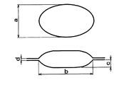
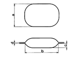
- FIG. 3 is a diagram showing a correlation between moisture, crushing strength, and apparent density of a molded body. It is a figure which shows the pocket [1st shape (single-sided pillow shape)] of a roll pocket. It is a figure which shows the pocket [2nd shape (double-sided almond shape)] of a roll pocket. It is a figure which shows the pocket [3rd shape (double-sided almond shape)] of a roll pocket. It is a figure which shows the pocket [4th shape (double-sided pillow shape)] of a roll pocket. It is a process flow of another Example (Example 3).
- FIG. 1 is a diagram showing a process for producing a coal-cast fuel of the present application in Embodiment 1.
- the manufacturing process in Embodiment 1 has a crushing process 10, a drying process 20, a crushing process 30, and a molding process 40, crushing the coal 1 as a raw material, drying it, crushing the dried coal, obtain.
- the molded body 100 obtained by molding the coal particles is used as a coal molded fuel.
- the raw coal 1 is lignite or subbituminous coal with a water content of 25 wt% or more. Preferably, lignite with a water content of 30 wt% or more is used. Only the coal 1 is used as a raw material, and no binder or additive is used. Use of an additive such as a binder causes a cost increase. However, since the coal-molded fuel of the present invention uses only coal without adding a binder, desired strength can be obtained at low cost. In the crushing step 10, the coal 1 is crushed with a jaw crusher or a hammer crusher to obtain a crushed coal 2, and the drying step 20 is performed.
- the coal 1 may be crushed to a size that can be charged into a ball mill or the like used in the subsequent crushing step 30, and is not particularly limited.
- the average particle diameter is preferably about 1 mm to 20 mm, more preferably 50 mm or less, more preferably 20 mm or less.
- the crushed coal 2 is dried by an indirect dryer to obtain the dried coal 3, and the pulverization step 30 is performed.
- a steam tube dryer may be used as the indirect dryer. Since a large amount of processing is required in the production of solid fuel, it is preferable to use a steam tube dryer that has a large heat transfer area and can be subjected to a large amount of drying treatment.
- the dried coal 3 is pulverized by the pulverizer, and the coal particles 4 are obtained and the process proceeds to the molding step 40.
- the pulverizer is a dry pulverization method or a dry pulverization method.
- a ball mill or roller mill capable of fine pulverization and suitable for mass processing is used.
- a pulverizer suitable for mass processing is preferable.
- the average particle diameter of the coal particles 4 is 10 to 60 ⁇ m, preferably 10 to 50 ⁇ m, more preferably 10 to 30 ⁇ m.
- the term “coal particles” means the coal particles 4 pulverized by the pulverization step 30.
- the filling rate into the mold (roll pocket) is increased.
- a desired strength can be obtained by improving the density of the molded body 100 described later.
- the ball mill and the roller mill can be dried simultaneously with the pulverization, the ball mill and the roller mill may be dried in the pulverization step 30, but the drying capability in the ball mill and the roller mill is insufficient.
- a drying step 20 is provided in advance to ensure the necessary drying capacity.
- the coal particles 4 are molded by a molding machine, and the obtained molded body 100 is used as a coal molding fuel.
- a molding machine for example, a briquette machine having a screw feeder is used, and a compact 100 as a coal molding fuel is obtained by filling and pressurizing the coal particles 4 in a roll pocket (molding mold).
- the pocket shape of the roll pocket is shown in FIGS. 4 to 7, but other shape pockets may be used.
- 4 is a pillow shape (first shape) with one side being flat
- FIG. 5 is a double-sided almond shape (elliptical pocket opening shape) (second shape)
- FIG. 6 is a double-sided almond shape (pocket opening shape is rectangular).
- 7 is a double-sided pillow shape (fourth shape).
- the size of the molded body 100 is preferably 5 to 40 mm at the maximum length and width.
- the apparent density of the molded body 100 is 1.2 to 1.4 g / cm 3 .
- the weight of the molded body 100 is preferably 0.2 to 20 g.
- the water content of the molded body 100 is 5 to 20 wt%, preferably 8 to 18 wt%, and more preferably 10 to 17 wt%. This moisture is derived from the moisture of the coal particles 4.
- the water content of the coal particles 4 used in the molding step 40 is preferably 5 to 20 wt%, more preferably 8 to 18 wt%, and even more preferably 10 to 17 wt%.
- Embodiment 1 since the particle diameter of the coal particles 4 is as fine as 10 to 60 ⁇ m, the filling rate of the roll pocket in the briquette machine increases during molding. Thereby, the density of the molded object 100 improves and it contributes to the intensity
- FIG. Further, the moisture contained in the coal 1 is utilized as a binder, and the moisture content is preferably set to 5 to 20 wt%, and the density of the molded body 100 is regulated, so that the size and weight of the molded body 100 are more preferable. It is also possible to adjust to a region where the crushing strength of the molded body 100 is maximized.
- the manufacturing process for obtaining the molded body 100 uses all known machines and devices, and does not require hot water or the like, so that the cost can be reduced.
- the binder is not used in the first embodiment.
- the strength of the molded body 100 can be set to a desired value at low cost without adding a separate binder. Is.
- FIG. 2 is a diagram showing manufacturing steps in the second embodiment.
- the basic configuration is the same as that of the first embodiment, but in the second embodiment, the second crushing process 50 is provided after the molding process 40 in the first embodiment, and the second molding process 60 is further provided in the subsequent stage.
- the second embodiment is different from the first embodiment in that the second molded body 200 obtained in the second molding step 60 is used as a coal molding fuel.
- molding process 40 which are common in Embodiment 1 are distinguished as the 1st crushing process 10 and the 1st shaping
- the molded body 100 obtained in the first molding process 40 is the first molded body 100.
- the density of the first molded body 100 in the second embodiment is preferably lower than the density of the first molded body 100 in the first embodiment, and the apparent density is 1.00 g / cm 3 to 1.25 g / cm 3 . It is preferable.
- the crushing strength is preferably 10 to 800N.
- the moisture content of the coal particles 4 used in the first molding step 40 is preferably 5 to 20 wt%, more preferably 8 to 18 wt%, and further preferably 10 to 17 wt%.
- the first molded body 100 is crushed by a crusher to obtain the first molded body crushed material 110, and the process proceeds to the second molding step 60.
- the crusher is the same as that used in the first crushing step 10.
- the first crushed material 110 has an average diameter of preferably 0.1 to 1.0 mm, more preferably 0.15 to 0.9 mm, and still more preferably 0.2 to 0.8 mm.
- the maximum particle diameter of the 1st molded object crushed object 110 is below the length of the shorter one of the two vertical and horizontal sides of the particle diameter of the 2nd molded object 200 mentioned later.
- the roll pocket in the briquette machine is formed when the second molded body 200 is molded.
- the filling rate can be improved.
- the resulting second molded body 200 exhibits superior quality (crushing strength and apparent density) compared to the first molded body 100 that is the final product (coal molded fuel) of the first embodiment.
- the pocket size (particle diameter) of the roll pocket size (particle diameter) used in the first molding step 40 and the second molding step 60 may not be the same.
- the second molded body 200 is obtained by molding the first molded body crushed material 110 with a molding machine.
- the particle size of the second molded body 200 is preferably 5 to 40 mm.
- the apparent density of the second molded body 200 is 1.2 to 1.4 g / cm 3 .
- the weight of the second molded body 200 is preferably 0.2 to 20 g.
- the water content of the second molded body 200 is 5 to 20 wt%, preferably 8 to 18 wt%, more preferably 10 to 17 wt%.
- the first molded body 100 once molded is crushed again in the second crushing step 50 and is molded again in the second molding step 60.
- the first molded body 100 is in a state in which the density has already been increased to some extent by the first molding step 40, and the first molded body crushed material 110 has a similar density. Therefore, it becomes possible to obtain the 2nd molded object 200 which further improved the density rather than the 1st molded object 100 by forming the 1st molded object crushed object 110 again by a briquette machine.
- the average particle size of the pulverized coal particles 4 is 10 to 60 ⁇ m, and as it is, the fluidity in the briquette machine is poor and it may be difficult to mold.
- the fluidity in the briquette machine is improved because the density is increased to some extent by the first molding step 40, and the second molding step 60. The molding is performed smoothly. As a result, a second molded body 200 having a higher density than that of the first molded body 100 is obtained. By using the second molded body 200 as a coal molded fuel, pulverization during storage and transportation is further reduced. Thus, a coal-molded fuel with improved handling properties can be obtained.
- a moisture adjustment step 70 for adjusting the moisture content of the first molded body 100 and the second molded body 200 that are finally obtained may be provided.
- the moisture adjustment step 70 is preferably provided after molding. That is, after the molding step 40 is preferable in the first embodiment, and after the second molding step 60 is preferable in the second embodiment.
- the moisture adjustment process 70 can prevent dust generation and spontaneous heat generation of the product.
- a belt conveyor is disposed, and a watering facility including a water supply pump and a spray nozzle is disposed on the belt conveyor, and the belt There is a method of spraying water on the first molded body 100 (or the second molded body 200) conveyed by the conveyor so that the moisture of the first molded body 100 (or the second molded body 200) is within a suitable range.
- moisture content of the 2nd molded object 200 piled up by the watering equipment comprised with a water supply pump and a sprinkler is made into a suitable range. It may be a method of adjusting to the above.
- the moisture after the moisture adjustment step 70 of the first molded body 100 (or the second molded body 200) is preferably 10 to 30 wt%, more preferably 10 wt% or more and less than 25 wt%.
- the strength of the second molded body 200 can be set to a desired value at a low cost without adding a binder as in the first embodiment.
- Example 1 corresponds to the manufacturing method of Embodiment 1, and uses the molded body 100 obtained in the first molding step 40 (hereinafter referred to as the first molded body 100) as a coal molded fuel. Crushing strength and apparent density were evaluated as product quality of briquettes.
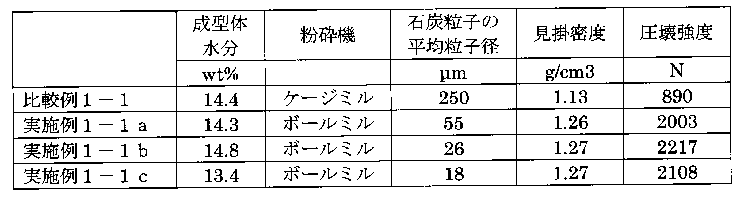
- Example 1-1 The raw material coal (brown coal with a water content of 46 wt%) is crushed to an average particle size of 10 mm or less using a hammer crusher (first crushing step 10), and the moisture is adjusted to a range of 13 to 15 wt% using a steam tube dryer. Dried (drying step 20). Further, coal particles 4 having different average particle diameters were obtained using a ball mill. The average particle diameter of the coal particles 4 is three types of 18 ⁇ m, 26 ⁇ m, and 55 ⁇ m (grinding step 30). The coal particles 4 were supplied to a briquette machine and molded without adding a binder to obtain a first molded body 100 (first molding step 40). The crushing strength, apparent density, and moisture of the obtained first molded body 100 were measured. The roller support pressure in the first molding step 40 is 5 t / cm, and the distance between the two rollers is 1 mm.
- Example 1-1 the roll pocket size is a pillow shape (length 38 ⁇ width 38 ⁇ depth 10 mm) (first shape, see FIG. 4), and the volume of the roll pocket is 8.08 cm 3 .
- the roll pocket is provided only on one roller, and the other roller is a flat surface. Therefore, in the first molded body 100 in Example 1-1, the shape of the roll pocket is transferred to only one molding surface, and the other is molded while remaining flat.
- Example 1-1 examples in which the average particle diameter of the coal particles 4 is changed to 55 ⁇ m, 26 ⁇ m, and 18 ⁇ m are shown in Table 1-1 as Examples 1-1a, 1-1b, and 1-1c, respectively.
- the roll pocket size is indicated as a for vertical, b for horizontal, c for depth, and d for the distance between rollers (the same applies to FIGS. 5 to 7).
- the water content of the first molded body 100 was measured based on the “total moisture measurement method for coals” of JIS M 8820-2000.
- the crushing strength of the first molded body 100 is measured based on “3.1 Crushing strength test method” of JIS Z 8841-1993, and the apparent density is the density and specific gravity of JIS Z 8807 “8.
- the measurement was performed based on the measurement method.
- the average particle size of the coal crushed in the first crushing step 10 is measured based on JISM8801-2004 “5. Particle size test method”, and the passing sieve mass percentage of each sieve opening is obtained. The passing sieve mass percentage is 50%. This particle size was defined as the average particle size.
- the average particle diameter of the coal particles 4 pulverized in the pulverization step 30 is a median diameter of a particle size distribution obtained by a laser diffraction / scattering method. All the following examples and comparative examples were measured by the same test method.
- Example 1-2 In Example 1-2, the roll pocket size was changed, and a roll pocket was provided for each of the two rollers in the briquette machine. The rest is the same as in Example 1-1.
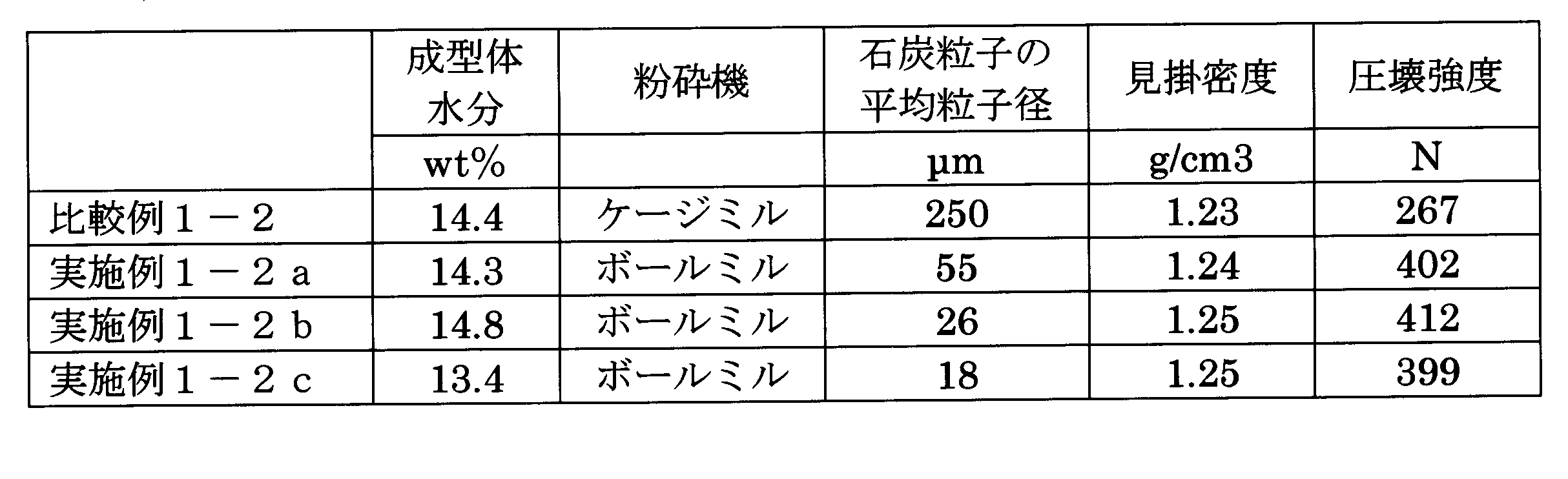
- Example 1-2 the roll pocket size is an almond shape having a length of 18 ⁇ width of 27 ⁇ depth of 4.15 mm (second shape, see FIG. 5), and the volume per roll pocket is 1.04 cm 3 (see FIG. 5). Table 1-2). Since the roll pocket is provided in both of the two rollers, the shape of the roll pocket is transferred to both surfaces of the first molded body 100 in Example 1-2. Also in Example 1-2, the average particle diameter of the coal particles 4 was changed to 55 ⁇ m, 26 ⁇ m, and 18 ⁇ m, and Examples 1-2a, 1-2b, and 1-2c are shown in Table 1-2, respectively.
- Example 1-3 The same as Example 1-2, except that the roll pocket size was changed.
- the roll pocket size in Example 1-3 is an almond shape having a length of 10 ⁇ width of 15 ⁇ depth of 2.6 mm (third shape, see FIG. 6), and the volume per roll pocket is 0.2 cm 3 (see FIG. 6). Table 1-3).
- the shape of the roll pocket is transferred to both sides of the molded body.
- the average particle diameter of the coal particles 4 was changed to 55 ⁇ m, 26 ⁇ m, and 18 ⁇ m, and Examples 1-3a, 1-3b, and 1-3c are shown in Table 1-3, respectively.
- Example 1-4 is the same as Example 1-2 except that the roll pocket size is changed.
- the roll pocket size in Example 1-4 is 6 ⁇ 9 ⁇ width ⁇ 1.57 mm pillow shape (see FIG. 7), and the volume per roll pocket is 0.035 cm 3 (fourth shape, Table 1-4).
- the shape of the roll pocket is transferred to both sides of the molded body.
- the average particle diameter of the coal particles 4 was changed to 55 ⁇ m, 26 ⁇ m, and 18 ⁇ m, and Examples 1-4a, 1-4b, and 1-4c are shown in Table 1-4, respectively.
- Example 1-1a to 1-1d the average particle diameter of the coal particles 4 is changed.
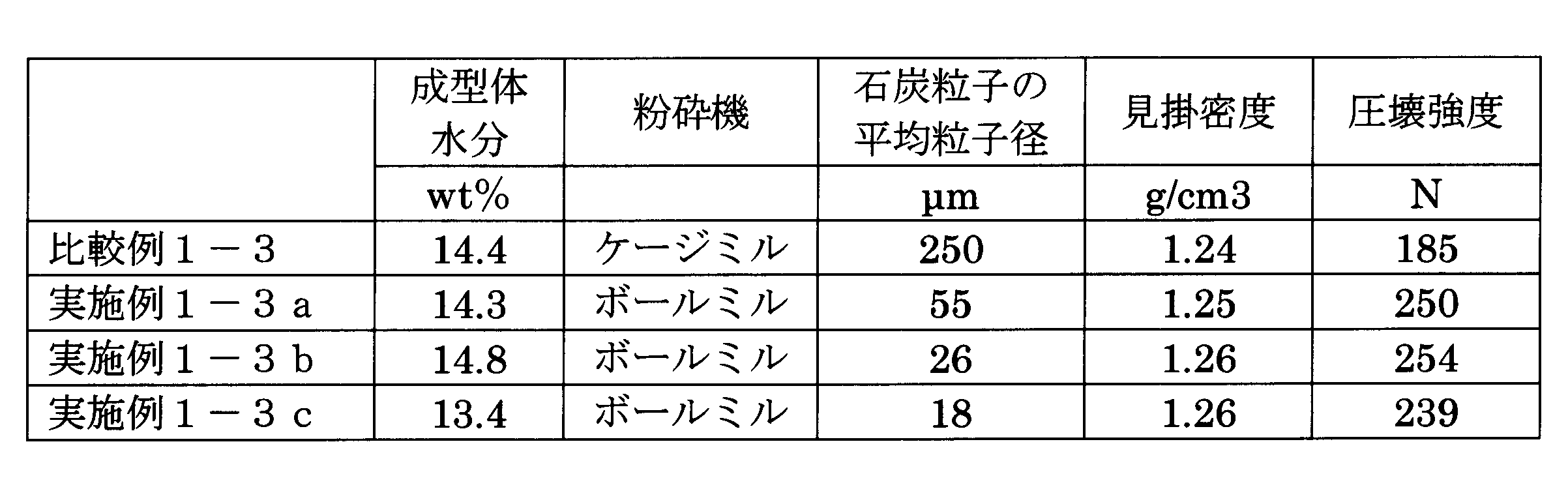
- the apparent density and crushing strength of the first molded body 100 are the same as those in Comparative Example 1-1. It exceeds the predetermined value. This indicates that even if the average particle diameter of the coal particles 4 changes within a predetermined range (10 to 60 ⁇ m), the apparent density and crushing strength of the first molded body 100 are not significantly affected. Similar results were obtained in Example 1-2a to Example 1-2d, Example 1-3a to Example 1-3d, and Example 1-4a to Example 1-4d.
- the quality of the first molded body 100 is good when the particle diameter is in the range of 10 to 60 ⁇ m, preferably 15 to 58 ⁇ m, more preferably 18 to 55 ⁇ m.
- the particle diameter is in the range of 10 to 60 ⁇ m, preferably 15 to 58 ⁇ m, more preferably 18 to 55 ⁇ m.
- an appropriate average diameter after ball milling is 10 ⁇ m or more.
- Example 2 corresponds to the manufacturing method of Embodiment 2, and uses the second molded body 200 obtained in the second molding step 60 as a coal molded fuel.
- the roller support pressure in the first molding step 40 and the second molding step 60 in Example 2 is 5 t / cm, and the distance between the two rollers is 1 mm. Further, as in Example 1, in Example 2, molding is performed without adding a binder or the like.
- Example 2-1 the first molded body 100 is pulverized and molded again.
- the apparent density of the first molded body 100 in Example 2-1 is lower than the apparent density of the first molded body 100 in Example 1-2, and is preferably 1.00 to 1.25 g / cm 3 . is there.
- As a method of obtaining the 1st molded object 100 with a low apparent density there exist methods, such as the rotation speed fall of the pressing screw of a roll upper part, roll rotation speed increase, and a roll support pressure fall, These may be compounded.
- the apparent density of 1.00 to 1.25 g / cm 3 is achieved by setting the roll rotation speed to twice that of the first molding step 40 of Example 1-2.
- a first molded body 100 was obtained.
- the obtained first molded body 100 is pulverized again with a hammer crusher to an average particle diameter of 0.1 to 1.0 mm and a maximum particle diameter of 18 mm or less (second crushing step 50), and the obtained first molded body crushed material 110 is obtained.
- moisture content were measured.
- the size of the roll pocket in the second molding step 60 is an almond shape (second shape) of length 18 ⁇ width 27 ⁇ depth 4.15 mm, and the average particle diameter of the coal particles 4 Examples of 55 ⁇ m, 26 ⁇ m, and 18 ⁇ m are shown in Table 2-1 as Examples 2-1a, 2-1b, and 2-1c, respectively.
- the quality of the first molded body 100, the mass percentage of the passing sieve of the first molded body crushed material 110, and the average diameter in Example 2-1 are shown.
- Example 1-2a, Example 1-2b, and Example 1-2c of one-time molding with three types of coal particle sizes are also shown.
- the first molded body 100 is used as a coal molded fuel
- the second molded body 200 is used as a coal molded fuel, and this is also indicated in the table (hereinafter referred to as Table 2-2). The same applies to Table 2-3).
- Example 2-2 the first molded body 100 is pulverized and molded again.
- the first molding step 40 the first molded body 100 having an apparent density of 1.00 to 1.25 g / cm 3 is obtained by setting the roll rotation speed to twice that of the first molding step 60 of Example 1-3. Obtained.
- the second molded body 200 obtained by pulverizing and molding the first molded body 100 again with a hammer crusher to an average particle diameter of 0.1 to 1.0 mm and a maximum particle diameter of 10 mm or less was used. Was measured.
- the size of the roll pocket in the second molding step 60 is an almond shape (third shape) of 10 ⁇ 15 ⁇ 2.6 mm in depth as in Example 1-3, and the average particle diameter of coal particles 4 is 55 ⁇ m. , 26 ⁇ m, and 18 ⁇ m are shown in Table 2-2 as Examples 2-2a, 2-2b, and 2-2c, respectively.
- the quality of the first molded body 100, the mass percentage passing through the first molded body crushed material 110, and the average diameter in Example 2-2 are shown.
- Example 1-3a, Example 1-3b, and Example 1-3c of one-time molding with three types of coal particle sizes are also shown.
- Example 2-3 the first molded body 100 is pulverized and molded again.
- the first molded body 100 having an apparent density of 1.00 to 1.25 g / cm 3 is obtained by setting the roll rotation speed to twice that of the first molding step 60 of Example 1-4. Obtained.
- the second molded body 200 obtained by pulverizing and molding the obtained first molded body 100 again with a hammer crusher to an average particle size of 0.1 to 1.0 mm and 6 mm or less, crushing strength, apparent density, moisture was measured.
- the size of the roll pocket in the second molding step 60 is a pillow shape (fourth shape) of length 6 ⁇ width 9 ⁇ depth 1.57 mm, similar to Example 1-4, and the average particle diameter of coal particles 4 is 55 ⁇ m.
- 26 ⁇ m, and 18 ⁇ m are shown in Table 2-3 as Examples 2-3a, 2-3b, and 2-3c, respectively.
- the quality of the first molded body 100, the mass percentage passing through the first molded body crushed material 110, and the average diameter in Example 2-3 are shown.
- Example 1-3a, Example 1-3b, and Example 1-3c of one-time molding with three types of coal particle sizes are also shown.
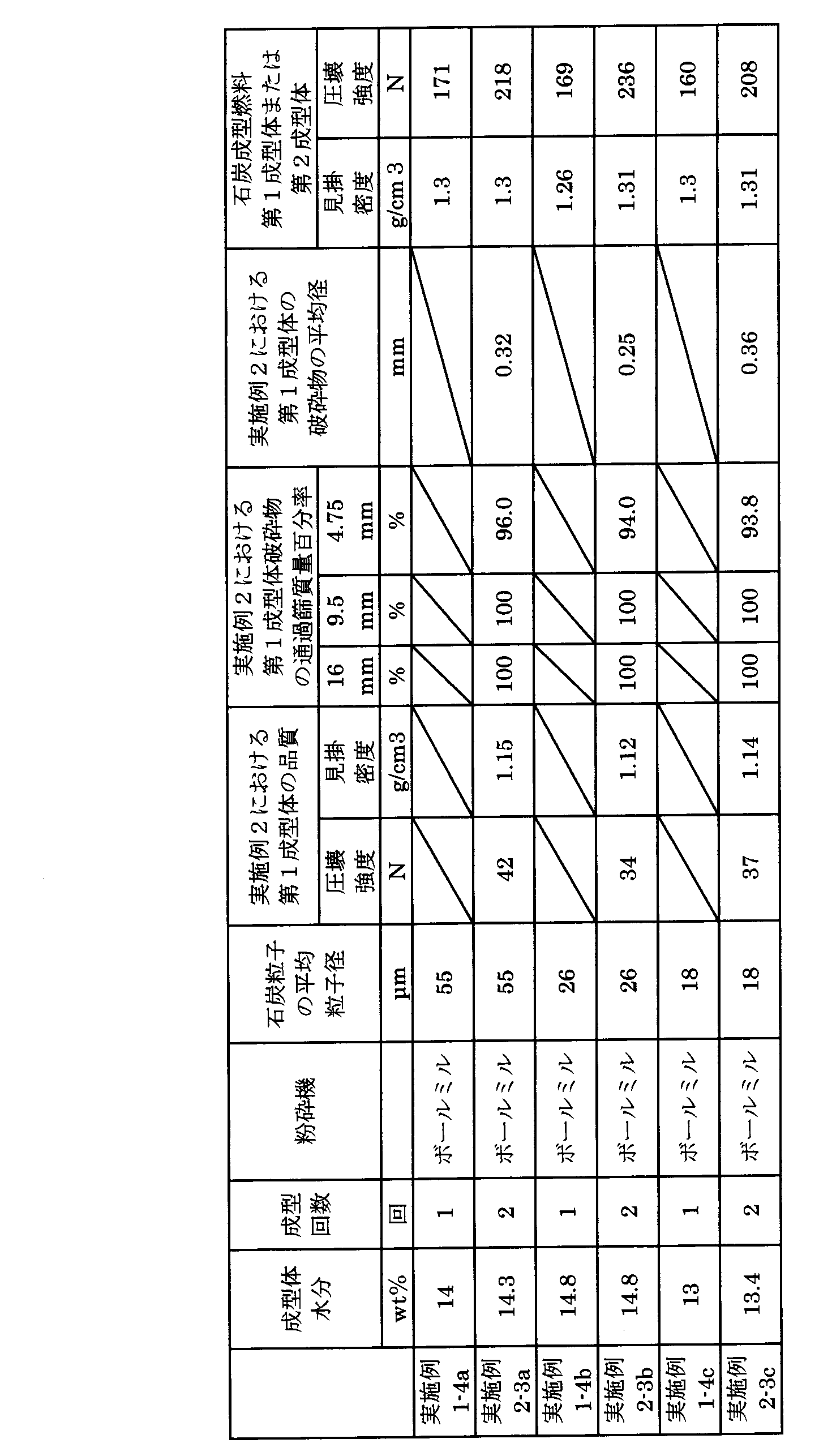
- the apparent density and crushing strength of the average particle diameter of all the coal particles 4 are examples that have undergone two molding steps (first and second molding steps 40, 60).
- 2-1, 2-2, and 2-3 were better in quality than Examples 1-2, 1-3, and 1-4 in which only one molding process (first molding process 40) was performed. . Therefore, it was confirmed that as the coal-molded fuel, the second molded body 200 that was molded twice showed better quality than the first molded body 100 obtained only by one molding.
- Example 2-1a Similar to the case where the average particle size of the coal particles 4 is changed in Example 1-1a to Example 1-1d, even if the average particle size of the coal particles 4 is changed in Example 2-1, 2 It is shown that the apparent density and crushing strength of the molded body 200 are not significantly affected (see Table 2-1 Example 2-1a to Example 2-1c). The same applies to Example 2-2a to Example 2-2c and Example 2-3a to Example 2-3c.
- the average particle diameter of the coal particles 4 is 10 to 60 ⁇ m, preferably 15 to 58 ⁇ m, and more preferably. In the range of 18 to 55 ⁇ m, it was confirmed that the quality of the second molded body 200 was good.
- Example 2-4 to Example 2-8 A second molded body 200 was produced in the same manner as in Example 2-1b except that the moisture of the second molded body 200 was changed, and the crushing strength and the apparent density were measured (Table 3).
- FIG. 3 is a diagram showing the correlation between the moisture-crushing strength-apparent density of the second molded body 200 in Table 3. As shown in Table 3 and FIG. 3, in Examples 2-4 to 2-8, the moisture of the second molded body 200 is in the range of 5 to 20 wt%, and the moisture of the second molded body 200 is in this range. The crushing strength and apparent density of the product are higher than those of Comparative Examples 2-1 and 2-2.
- FIG. 8 is a process flow for producing the moisture-adjusted product 300 in the third embodiment.
- moisture is added to the second molded body 200 to form a coal molded fuel.
- molding is performed without using a binder.
- the second molded body 200 was produced using lignite with a moisture content of 38 wt% (different from that used in Example 1-1) as a raw material.
- the moisture adjustment process 70 which adds a water
- Moisture adjustment was carried out by a method of watering the second molded body 200 transported by the belt conveyor by arranging a watering facility including a water supply pump and a spray nozzle on the belt conveyor.
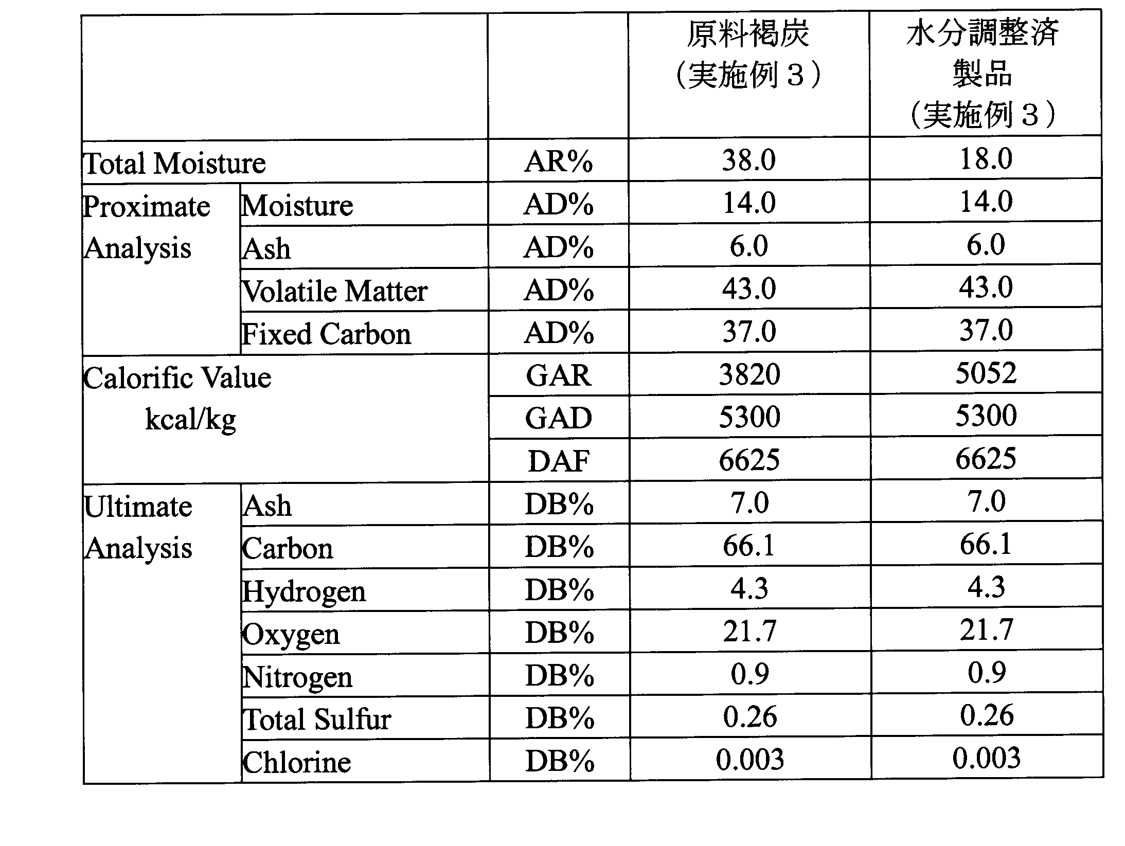
- Table 4 shows the properties of the used lignite and the obtained water-adjusted product 300.
- AR is arrival-based and AD is air-drying (JIS M8810).
- DB represents anhydrous base
- GAR, GAD, and DAF represent arrival base high calorific value, air dry base high calorific value, and anhydrous ashless base high calorific value (JIS M8810).
- the numerical values on the respective steps 10 to 70 in FIG. 8 indicate the inlet moisture and the outlet moisture in each of the steps 10 to 70, respectively.
- C1 to C7 shown between the steps 10 to 70 indicate the properties and amount of coal between the steps (see Table 5). That is, in C1, raw material lignite 1 (total moisture 38.0%) before drying is supplied at 215 t / h, and in C7, the moisture-adjusted product 300 (total moisture 18.0%) hydrolyzed in the moisture adjustment step 70 is 163 t. / H Indicates that it can be obtained. Table 6 shows the crushing strength and apparent density of the moisture-adjusted product 300 together with the results of Example 2-3b before moisture adjustment.
- Example 3 moisture is added to the second molded body 200 to obtain a moisture-adjusted product 300, and the moisture-adjusted product 300 is used as a coal-molded fuel.
- this moisture-adjusted product 300 it was confirmed that the crushing strength and the calorific value equivalent to those of Examples 1 and 2 were obtained while suppressing dust generation and heat generation by adding water (see Table 6).
- moisture was added to the second molded body 200 of Example 2-3b. However, moisture may be added to another second molded body 200 of Example 2, or the first of Example 1 may be used. Water may be added to the molded body 100.
- the first molded body 100 and the second molded body 200 having desired strength can be obtained without adding a binder or the like in the present invention. Therefore, it is possible to obtain a coal-molded fuel with high strength and excellent handling properties at low cost without using an additive such as a binder that causes an increase in cost.
Landscapes
- Chemical & Material Sciences (AREA)
- Life Sciences & Earth Sciences (AREA)
- Environmental & Geological Engineering (AREA)
- Oil, Petroleum & Natural Gas (AREA)
- Organic Chemistry (AREA)
- General Life Sciences & Earth Sciences (AREA)
- Geochemistry & Mineralogy (AREA)
- Geology (AREA)
- Ecology (AREA)
- Forests & Forestry (AREA)
- Wood Science & Technology (AREA)
- Biodiversity & Conservation Biology (AREA)
- Engineering & Computer Science (AREA)
- Solid Fuels And Fuel-Associated Substances (AREA)
Abstract
Description
図1は実施形態1における本願石炭成型燃料の製造工程を示す図である。実施形態1における製造工程は、破砕工程10、乾燥工程20、粉砕工程30、成型工程40を有し、原料となる石炭1を破砕した後乾燥させ、乾燥させた石炭を粉砕して石炭粒子を得る。この石炭粒子を成型することにより得られた成型体100を、石炭成型燃料とするものである。
図2は実施形態2における製造工程を示す図である。基本構成は実施形態1と同様であるが、実施形態2では実施形態1における成型工程40の後段に第2破砕工程50を設け、さらにその後段に第2成型工程60を設ける。この第2成型工程60で得られた第2成型体200を石炭成型燃料とする点で、実施形態1と異なる。
実施例1は実施形態1の製造方法に対応し、第1成型工程40で得られた成型体100(以降第1成型体100)を石炭成型燃料とするものである。ブリケットの製品品質として、圧壊強度および見掛密度を評価した。
原料となる石炭(水分46wt%の褐炭)をハンマークラッシャーを用いて平均粒子径10mm以下に破砕し(第1破砕工程10)、スチームチューブドライヤを用いて水分を13~15wt%の範囲になるように乾燥させた(乾燥工程20)。さらにボールミルを用いて平均粒子径の異なる石炭粒子4を得た。石炭粒子4の平均粒子径は18μm、26μm、55μmの3種である(粉砕工程30)。この石炭粒子4をブリケットマシンに供給し、バインダーを添加することなく成型を行って第1成型体100を得た(第1成型工程40)。得られた第1成型体100の圧壊強度および見掛密度、水分を測定した。第1成型工程40におけるローラ支持圧は5t/cm、2つのローラ同士の間隔は1mmである。
実施例1-2ではロールポケットサイズを変更するとともに、ブリケットマシンにおける2つのローラそれぞれにロールポケットを設けた。それ以外は実施例1-1と同様である。
ロールポケットサイズを変更した以外は実施例1-2と同様である。実施例1-3におけるロールポケットサイズは縦10×横15×深さ2.6mmのアーモンド形状(第3の形状、図6参照)、ロールポケット1つ当たりの容積は0.2cm3である(表1-3)。実施例1-3における第1成型体100も成型された両面にロールポケットの形状が転写される。石炭粒子4の平均粒子径を55μm、26μm、18μmに変更し、それぞれ実施例1-3a、1-3b、1-3cとして表1-3に示す。
実施例1-4においても、ロールポケットサイズを変更した以外は実施例1-2と同様である。実施例1-4におけるロールポケットサイズは縦6×横9×深さ1.57mmのピロー形状(図7参照)、ロールポケット1つ当たりの容積は0.035cm3である(第4の形状、表1-4)。実施例1-4における第1成型体100も成型された両面にロールポケットの形状が転写される。石炭粒子4の平均粒子径を55μm、26μm、18μmに変更し、それぞれ実施例1-4a、1-4b、1-4cとして表1-4に示す。
ケージミルを用い、石炭粒子4の平均粒子径を250μmとするとともに(粉砕工程30)、第1成型体100の水分が14.4wt%となるように調整した。それ以外は実施例1-1~実施例1-4と同様の方法で第1成型体100を作成し、圧壊強度および見掛密度を測定した(表1-1~表1-4)。

実施例2は実施形態2の製造方法に対応し、第2成型工程60で得られた第2成型体200を石炭成型燃料とするものである。なお、実施例2における第1成型工程40および第2成型工程60におけるローラ支持圧は5t/cm、2つのローラ同士の間隔は1mmである。また、実施例1と同様に実施例2においてもバインダー等を添加せずに成型を行う。
実施例2-1では第1成型体100を再度粉砕、成型するものである。ただし、実施例2-1における第1成型体100の見掛密度は実施例1-2の第1成型体100の見掛密度と比べ低く、好ましくは1.00~1.25g/cm3である。見掛密度の低い第1成型体100を得る方法としては、ロール上部の押込スクリュの回転数低下、ロール回転数増加、ロール支持圧の低下などの方法があり、これらを複合させても良い。実施例2-1の第1成型工程40では、ロール回転数を実施例1-2の第1成型工程40の2倍とすることで、見掛密度1.00~1.25g/cm3の第1成型体100を得た。得られた第1成型体100をハンマークラッシャーで平均粒子径0.1~1.0mmかつ最大粒子径18mm以下に再度粉砕(第2破砕工程50)し、得られた第1成型体破砕物110をブリケットマシンで再度成型した(第2成型工程60)。得られた第2成型体200につき、圧壊強度および見掛密度、水分を測定した。なお実施例1-2と同様、第2成型工程60におけるロールポケットのサイズは縦18×横27×深さ4.15mmのアーモンド形状(第2の形状)であり、石炭粒子4の平均粒子径55μm、26μm、18μmの例をそれぞれ実施例2-1a、2-1b、2-1cとして表2-1に示す。併せて、実施例2-1における第1成型体100の品質と第1成型体破砕物110の通過篩質量百分率と平均径を示す。
実施例2-2では第1成型体100を再度粉砕、成型する。第1成型工程40では、ロール回転数を実施例1-3の第1成型工程60の2倍とすることで、見掛密度1.00~1.25g/cm3の第1成型体100を得た。第1成型体100をハンマークラッシャーで平均粒子径0.1~1.0mmかつ最大粒子径10mm以下に再度粉砕、成型して得られた第2成型体200につき、圧壊強度および見掛密度、水分を測定した。第2成型工程60におけるロールポケットのサイズは実施例1-3と同様に縦10×横15×深さ2.6mmのアーモンド形状(第3の形状)であり、石炭粒子4の平均粒子径55μm、26μm、18μmの例をそれぞれ実施例2-2a、2-2b、2-2cとして表2-2に示す。併せて、実施例2-2における第1成型体100の品質と第1成型体破砕物110の通過篩質量百分率と平均径を示す。また、石炭粒子径ごとに成型回数の影響を評価するため、3種の石炭粒子径における1回成型の実施例1-3a、実施例1-3bおよび実施例1-3cを併記した。
実施例2-3では第1成型体100を再度粉砕、成型する。第1成型工程40では、ロール回転数を実施例1-4の第1成型工程60の2倍とすることで、見掛密度1.00~1.25g/cm3の第1成型体100を得た。得られた第1成型体100をハンマークラッシャーで平均粒子径0.1~1.0mmかつ6mm以下に再度粉砕、成型して得られた第2成型体200につき、圧壊強度および見掛密度、水分を測定した。第2成型工程60におけるロールポケットのサイズは実施例1-4と同様に縦6×横9×深さ1.57mmのピロー形状(第4の形状)であり、石炭粒子4の平均粒子径55μm、26μm、18μmの例をそれぞれ実施例2-3a、2-3b、2-3cとして表2-3に示す。併せて、実施例2-3における第1成型体100の品質と第1成型体破砕物110の通過篩質量百分率と平均径を示す。また、石炭粒子径ごとに成型回数の影響を評価するため、3種の石炭粒子径における1回成型の実施例1-3a、実施例1-3bおよび実施例1-3cを併記した。


第2成型体200の水分を変更した以外は、実施例2-1bと同様の方法で第2成型体200を製造し、圧壊強度および見掛密度を測定した(表3)。
同様に、第2成型体200の水分を変更した以外は実施例2-1bと同様の方法で第2成型体200を製造した(表3)。
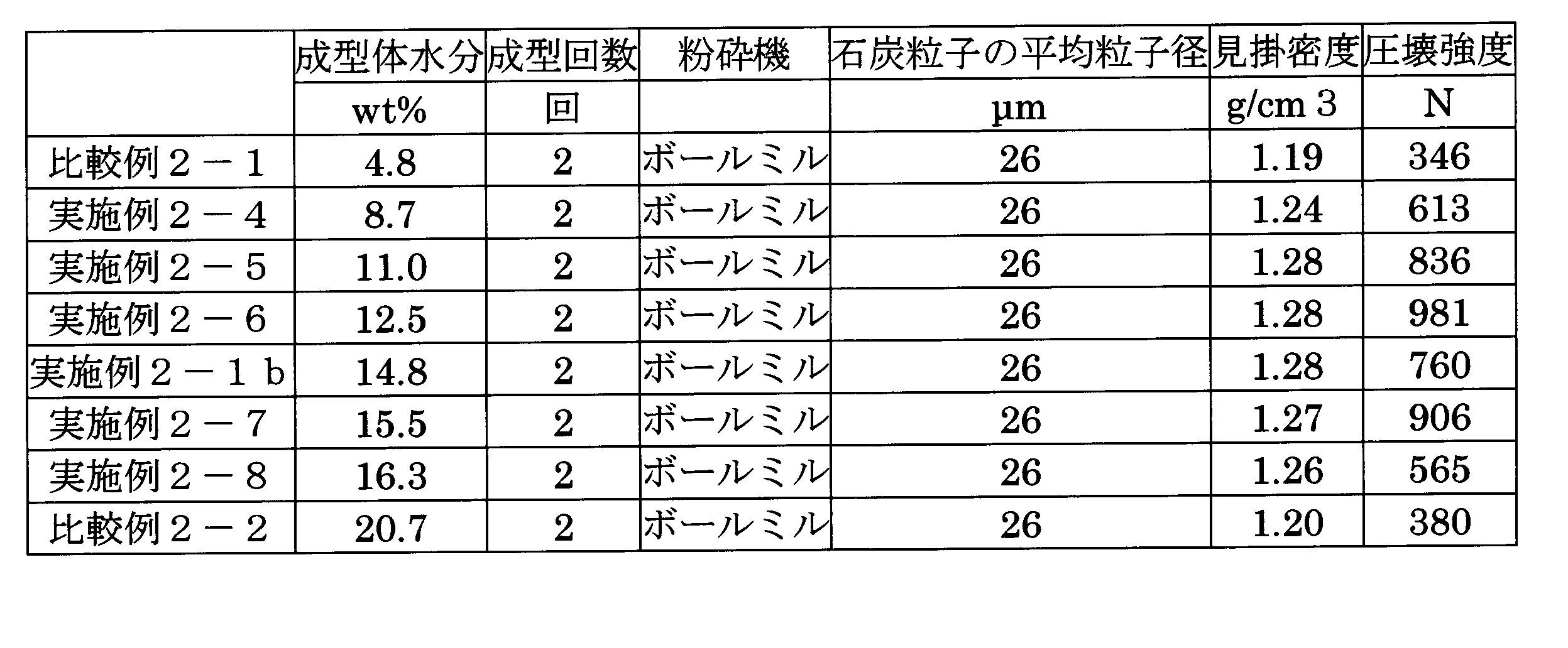
図8は実施例3において水分調整済製品300を作製するプロセスフローである。実施例3では発塵及び発熱抑制のために第2成型体200に水分を加え、石炭成型燃料とするものである。また実施例3においてもバインダーを用いることなく成型を行う。基本的には実施例2-3bと同様であるが、水分38wt%の褐炭(実施例1-1で用いたものとは異なる)を原料として第2成型体200を作製した。さらに、実施例3では第2成型体200に水分を加える水分調整工程70を追加し、水分調整済製品300を作製している。水分調整は、ベルトコンベア上部に給水ポンプおよびスプレーノズルで構成される散水設備を配し、ベルトコンベアによって搬送される第2成型体200に対し、散水する方法で実施した。用いた褐炭および得られた水分調整済製品300の性状を表4に示す。表4中、ARは到着ベース、ADは気乾ベースである(JIS M8810)。またDBは無水ベースを示し、GAR、GAD、DAFはそれぞれ到着ベース高位発熱量、気乾ベース高位発熱量、無水無灰ベース高位発熱量を示す(JIS M8810)。


2 破砕済みの石炭
3 乾燥済みの石炭
4 石炭粒子
10 第1破砕工程
20 乾燥工程
30 粉砕工程
40 第1成型工程
50 第2破砕工程
60 第2成型工程
100 第1成型体
110 第1成型体破砕物
200 第2成型体
300 水分調整済製品
Claims (6)
- 石炭を破砕した後に乾燥、粉砕して石炭粒子を得るとともに、この石炭粒子を成型して得られた成型体としての石炭成型燃料であって、
前記石炭粒子は、平均粒子径10~60μmであって、
前記成型体は、水分5~20wt%、見掛密度1.2~1.4g/cm3であること
を特徴とする石炭成型燃料。 - 請求項1に記載の石炭成型燃料において、
前記粉砕はボールミルまたはローラミルで行われること
を特徴とする石炭成型燃料。 - 請求項1または請求項2に記載の石炭成型燃料において、
前記石炭は、褐炭または亜瀝青炭であること
を特徴とする石炭成型燃料。 - 請求項1ないし請求項3のいずれか1項に記載の石炭成型燃料において、
前記成型体をさらに破砕し、再度成型した第2成型体を石炭成型燃料とすること
を特徴とする石炭成型燃料。 - 石炭を破砕する破砕工程と、
前記破砕工程で破砕された石炭を乾燥する乾燥工程と、
前記乾燥工程で乾燥された石炭を粉砕し、平均粒子径10~60μmの石炭粒子を得る粉砕工程と、
水分含有量が5~20wt%の前記石炭粒子を成型し、見掛密度1.2~1.4g/cm3の燃料としての成型体を得る成型工程と
を有する石炭成型燃料の製造方法。 - 石炭を破砕する第1破砕工程と、
前記第1破砕工程で破砕された石炭を乾燥する乾燥工程と、
前記乾燥工程で乾燥された石炭を粉砕し、平均粒子径10~60μmの石炭粒子を得る粉砕工程と、
水分含有量が5~20wt%の前記石炭粒子を成型し、第1成型体を得る第1成型工程と、
前記第1成型体を破砕して成型体破砕物を生成する第2破砕工程と、
前記成型体破砕物を再度成型して、見掛密度1.2~1.4g/cm3の第2成型体を生成する第2成型工程と、
を有する石炭成型燃料の製造方法。
Priority Applications (2)
| Application Number | Priority Date | Filing Date | Title |
|---|---|---|---|
| JP2015554942A JP6524914B2 (ja) | 2013-12-25 | 2014-12-24 | 石炭成型燃料およびその製造方法 |
| CN201480070450.6A CN105849239B (zh) | 2013-12-25 | 2014-12-24 | 成型煤燃料及其生产方法 |
Applications Claiming Priority (4)
| Application Number | Priority Date | Filing Date | Title |
|---|---|---|---|
| JP2013-266954 | 2013-12-25 | ||
| JP2013266954 | 2013-12-25 | ||
| JP2014-138078 | 2014-07-03 | ||
| JP2014138078 | 2014-07-03 |
Publications (1)
| Publication Number | Publication Date |
|---|---|
| WO2015098935A1 true WO2015098935A1 (ja) | 2015-07-02 |
Family
ID=53478786
Family Applications (1)
| Application Number | Title | Priority Date | Filing Date |
|---|---|---|---|
| PCT/JP2014/084090 Ceased WO2015098935A1 (ja) | 2013-12-25 | 2014-12-24 | 石炭成型燃料およびその製造方法 |
Country Status (3)
| Country | Link |
|---|---|
| JP (2) | JP6524914B2 (ja) |
| CN (1) | CN105849239B (ja) |
| WO (1) | WO2015098935A1 (ja) |
Cited By (11)
| Publication number | Priority date | Publication date | Assignee | Title |
|---|---|---|---|---|
| WO2017138422A1 (ja) * | 2016-02-09 | 2017-08-17 | 宇部興産株式会社 | 石炭成型燃料の製造方法 |
| WO2018037809A1 (ja) * | 2016-08-24 | 2018-03-01 | 株式会社神戸製鋼所 | 固形燃料の製造方法 |
| JP2018030951A (ja) * | 2016-08-24 | 2018-03-01 | 株式会社神戸製鋼所 | 固形燃料の製造方法 |
| WO2018079713A1 (ja) * | 2016-10-27 | 2018-05-03 | 宇部興産株式会社 | 石炭成型燃料の製造方法および石炭成型燃料 |
| WO2018079706A1 (ja) * | 2016-10-27 | 2018-05-03 | 宇部興産株式会社 | 石炭成型燃料の製造方法および石炭成型燃料 |
| JP2018165290A (ja) * | 2017-03-28 | 2018-10-25 | 宇部興産株式会社 | 改質炭集合体およびその製造方法 |
| JP2018168235A (ja) * | 2017-03-29 | 2018-11-01 | 宇部興産株式会社 | 改質炭の養生方法 |
| JP2018168230A (ja) * | 2017-03-29 | 2018-11-01 | 宇部興産株式会社 | 石炭成型燃料の製造方法 |
| JP2018168247A (ja) * | 2017-03-29 | 2018-11-01 | 宇部興産株式会社 | 石炭成型体の製造方法 |
| JP2019038942A (ja) * | 2017-08-25 | 2019-03-14 | 宇部興産株式会社 | 石炭成型燃料の製造方法 |
| JP2020519703A (ja) * | 2017-04-13 | 2020-07-02 | ティッセンクルップ インダストリアル ソリューションズ アクツィエンゲゼルシャフトThyssenKrupp Industrial Solutions AG | 炭素質投入材料を圧密するためのデバイスおよび方法、ならびにそれらの使用 |
Families Citing this family (1)
| Publication number | Priority date | Publication date | Assignee | Title |
|---|---|---|---|---|
| CN113295577B (zh) * | 2021-05-25 | 2022-04-15 | 中国核动力研究设计院 | 一种包覆燃料颗粒疏松热解碳层表观密度测定方法 |
Citations (5)
| Publication number | Priority date | Publication date | Assignee | Title |
|---|---|---|---|---|
| JPS5481301A (en) * | 1977-12-13 | 1979-06-28 | Mitsubishi Chem Ind Ltd | Compression molding of coal powder |
| JPS5686993A (en) * | 1979-11-24 | 1981-07-15 | Kloeckner Humboldt Deutz Ag | Method of compressing and aggregating finely divided coal without bonding agent |
| JPS57179294A (en) * | 1981-04-07 | 1982-11-04 | Schwarze Pumpe Gas Veb | Manufacture of pyrolysis-resistant soft brown coal briquette |
| JPS58152095A (ja) * | 1982-03-04 | 1983-09-09 | Idemitsu Kosan Co Ltd | 低品位炭の改良方法 |
| JPS62121790A (ja) * | 1985-11-21 | 1987-06-03 | Kawasaki Heavy Ind Ltd | 脱水褐炭の成形方法 |
-
2014
- 2014-12-24 WO PCT/JP2014/084090 patent/WO2015098935A1/ja not_active Ceased
- 2014-12-24 CN CN201480070450.6A patent/CN105849239B/zh active Active
- 2014-12-24 JP JP2015554942A patent/JP6524914B2/ja active Active
-
2019
- 2019-02-27 JP JP2019033572A patent/JP2019116628A/ja active Pending
Patent Citations (5)
| Publication number | Priority date | Publication date | Assignee | Title |
|---|---|---|---|---|
| JPS5481301A (en) * | 1977-12-13 | 1979-06-28 | Mitsubishi Chem Ind Ltd | Compression molding of coal powder |
| JPS5686993A (en) * | 1979-11-24 | 1981-07-15 | Kloeckner Humboldt Deutz Ag | Method of compressing and aggregating finely divided coal without bonding agent |
| JPS57179294A (en) * | 1981-04-07 | 1982-11-04 | Schwarze Pumpe Gas Veb | Manufacture of pyrolysis-resistant soft brown coal briquette |
| JPS58152095A (ja) * | 1982-03-04 | 1983-09-09 | Idemitsu Kosan Co Ltd | 低品位炭の改良方法 |
| JPS62121790A (ja) * | 1985-11-21 | 1987-06-03 | Kawasaki Heavy Ind Ltd | 脱水褐炭の成形方法 |
Cited By (19)
| Publication number | Priority date | Publication date | Assignee | Title |
|---|---|---|---|---|
| WO2017138422A1 (ja) * | 2016-02-09 | 2017-08-17 | 宇部興産株式会社 | 石炭成型燃料の製造方法 |
| JPWO2017138422A1 (ja) * | 2016-02-09 | 2018-11-29 | 宇部興産株式会社 | 石炭成型燃料の製造方法 |
| WO2018037809A1 (ja) * | 2016-08-24 | 2018-03-01 | 株式会社神戸製鋼所 | 固形燃料の製造方法 |
| JP2018030950A (ja) * | 2016-08-24 | 2018-03-01 | 株式会社神戸製鋼所 | 固形燃料の製造方法 |
| JP2018030951A (ja) * | 2016-08-24 | 2018-03-01 | 株式会社神戸製鋼所 | 固形燃料の製造方法 |
| WO2018037808A1 (ja) * | 2016-08-24 | 2018-03-01 | 株式会社神戸製鋼所 | 固形燃料の製造方法 |
| JPWO2018079713A1 (ja) * | 2016-10-27 | 2019-09-19 | 宇部興産株式会社 | 石炭成型燃料の製造方法および石炭成型燃料 |
| WO2018079713A1 (ja) * | 2016-10-27 | 2018-05-03 | 宇部興産株式会社 | 石炭成型燃料の製造方法および石炭成型燃料 |
| WO2018079706A1 (ja) * | 2016-10-27 | 2018-05-03 | 宇部興産株式会社 | 石炭成型燃料の製造方法および石炭成型燃料 |
| JP7003930B2 (ja) | 2016-10-27 | 2022-01-21 | 宇部興産株式会社 | 石炭成型燃料の製造方法および石炭成型燃料 |
| JPWO2018079706A1 (ja) * | 2016-10-27 | 2019-09-19 | 宇部興産株式会社 | 石炭成型燃料の製造方法および石炭成型燃料 |
| JP2018165290A (ja) * | 2017-03-28 | 2018-10-25 | 宇部興産株式会社 | 改質炭集合体およびその製造方法 |
| JP2018168235A (ja) * | 2017-03-29 | 2018-11-01 | 宇部興産株式会社 | 改質炭の養生方法 |
| JP2018168247A (ja) * | 2017-03-29 | 2018-11-01 | 宇部興産株式会社 | 石炭成型体の製造方法 |
| JP2018168230A (ja) * | 2017-03-29 | 2018-11-01 | 宇部興産株式会社 | 石炭成型燃料の製造方法 |
| JP7066327B2 (ja) | 2017-03-29 | 2022-05-13 | Ube株式会社 | 改質炭の養生方法 |
| JP2020519703A (ja) * | 2017-04-13 | 2020-07-02 | ティッセンクルップ インダストリアル ソリューションズ アクツィエンゲゼルシャフトThyssenKrupp Industrial Solutions AG | 炭素質投入材料を圧密するためのデバイスおよび方法、ならびにそれらの使用 |
| JP7116083B2 (ja) | 2017-04-13 | 2022-08-09 | ティッセンクルップ インダストリアル ソリューションズ アクツィエンゲゼルシャフト | 炭素質投入材料を圧密するためのデバイスおよび方法、ならびにそれらの使用 |
| JP2019038942A (ja) * | 2017-08-25 | 2019-03-14 | 宇部興産株式会社 | 石炭成型燃料の製造方法 |
Also Published As
| Publication number | Publication date |
|---|---|
| JPWO2015098935A1 (ja) | 2017-03-23 |
| JP2019116628A (ja) | 2019-07-18 |
| CN105849239B (zh) | 2019-10-18 |
| CN105849239A (zh) | 2016-08-10 |
| JP6524914B2 (ja) | 2019-06-05 |
Similar Documents
| Publication | Publication Date | Title |
|---|---|---|
| JP6524914B2 (ja) | 石炭成型燃料およびその製造方法 | |
| JP6161242B2 (ja) | 混合燃料の製造方法 | |
| US9719040B2 (en) | Method and process for producing a water-resistant, mechanically stable form of torrefied biomass | |
| JP6777471B2 (ja) | カルシウムカーバイドの製造方法 | |
| JP2009051985A (ja) | バイオマス系成型燃料の製造方法 | |
| JP7003930B2 (ja) | 石炭成型燃料の製造方法および石炭成型燃料 | |
| JP6926592B2 (ja) | 石炭成型体の製造方法 | |
| JP6243982B2 (ja) | 混合燃料用の成型物の製造方法 | |
| JP3134558U (ja) | 固形燃料製造設備 | |
| JP2012046662A (ja) | 固体燃料の製造方法及び竪型ローラミル | |
| JP7066327B2 (ja) | 改質炭の養生方法 | |
| KR101638583B1 (ko) | 인공경량골재의 제조방법 | |
| JP6283724B2 (ja) | 混合燃料の製造方法 | |
| JP6062316B2 (ja) | 成型固形燃料の製造方法 | |
| CN203203053U (zh) | 粒度分级煤粉制备系统 | |
| JP2018165290A (ja) | 改質炭集合体およびその製造方法 | |
| JP7066326B2 (ja) | 改質炭の養生方法 | |
| WO2018079713A1 (ja) | 石炭成型燃料の製造方法および石炭成型燃料 | |
| CN103216841B (zh) | 粒度分级煤粉制备系统 | |
| JP2018168230A (ja) | 石炭成型燃料の製造方法 | |
| US9427744B1 (en) | Methods for processing carbonaceous materials | |
| KR101945111B1 (ko) | 석탄재와 탄소분말을 이용한 비드 및 그 제조방법 | |
| JP2017014525A (ja) | 混合燃料用の成型物 | |
| JP2017031416A (ja) | 混合燃料の製造方法及び成型物 | |
| JP2016199771A (ja) | 混合燃料の製造方法及び成型物 |
Legal Events
| Date | Code | Title | Description |
|---|---|---|---|
| 121 | Ep: the epo has been informed by wipo that ep was designated in this application |
Ref document number: 14875102 Country of ref document: EP Kind code of ref document: A1 |
|
| ENP | Entry into the national phase |
Ref document number: 2015554942 Country of ref document: JP Kind code of ref document: A |
|
| NENP | Non-entry into the national phase |
Ref country code: DE |
|
| WWE | Wipo information: entry into national phase |
Ref document number: IDP00201604829 Country of ref document: ID |
|
| 122 | Ep: pct application non-entry in european phase |
Ref document number: 14875102 Country of ref document: EP Kind code of ref document: A1 |