WO2015098644A1 - アルミニウム電解コンデンサ用電極箔及びその製造方法 - Google Patents
アルミニウム電解コンデンサ用電極箔及びその製造方法 Download PDFInfo
- Publication number
- WO2015098644A1 WO2015098644A1 PCT/JP2014/083381 JP2014083381W WO2015098644A1 WO 2015098644 A1 WO2015098644 A1 WO 2015098644A1 JP 2014083381 W JP2014083381 W JP 2014083381W WO 2015098644 A1 WO2015098644 A1 WO 2015098644A1
- Authority
- WO
- WIPO (PCT)
- Prior art keywords
- aluminum
- foil
- electrode foil
- electrolytic capacitor
- electrode
- Prior art date
- Legal status (The legal status is an assumption and is not a legal conclusion. Google has not performed a legal analysis and makes no representation as to the accuracy of the status listed.)
- Ceased
Links
Classifications
-
- H—ELECTRICITY
- H01—ELECTRIC ELEMENTS
- H01G—CAPACITORS; CAPACITORS, RECTIFIERS, DETECTORS, SWITCHING DEVICES, LIGHT-SENSITIVE OR TEMPERATURE-SENSITIVE DEVICES OF THE ELECTROLYTIC TYPE
- H01G9/00—Electrolytic capacitors, rectifiers, detectors, switching devices, light-sensitive or temperature-sensitive devices; Processes of their manufacture
- H01G9/004—Details
- H01G9/04—Electrodes or formation of dielectric layers thereon
- H01G9/042—Electrodes or formation of dielectric layers thereon characterised by the material
- H01G9/045—Electrodes or formation of dielectric layers thereon characterised by the material based on aluminium
-
- B—PERFORMING OPERATIONS; TRANSPORTING
- B22—CASTING; POWDER METALLURGY
- B22F—WORKING METALLIC POWDER; MANUFACTURE OF ARTICLES FROM METALLIC POWDER; MAKING METALLIC POWDER; APPARATUS OR DEVICES SPECIALLY ADAPTED FOR METALLIC POWDER
- B22F1/00—Metallic powder; Treatment of metallic powder, e.g. to facilitate working or to improve properties
- B22F1/05—Metallic powder characterised by the size or surface area of the particles
-
- B—PERFORMING OPERATIONS; TRANSPORTING
- B32—LAYERED PRODUCTS
- B32B—LAYERED PRODUCTS, i.e. PRODUCTS BUILT-UP OF STRATA OF FLAT OR NON-FLAT, e.g. CELLULAR OR HONEYCOMB, FORM
- B32B15/00—Layered products comprising a layer of metal
- B32B15/01—Layered products comprising a layer of metal all layers being exclusively metallic
- B32B15/016—Layered products comprising a layer of metal all layers being exclusively metallic all layers being formed of aluminium or aluminium alloys
-
- B—PERFORMING OPERATIONS; TRANSPORTING
- B32—LAYERED PRODUCTS
- B32B—LAYERED PRODUCTS, i.e. PRODUCTS BUILT-UP OF STRATA OF FLAT OR NON-FLAT, e.g. CELLULAR OR HONEYCOMB, FORM
- B32B15/00—Layered products comprising a layer of metal
- B32B15/04—Layered products comprising a layer of metal comprising metal as the main or only constituent of a layer, which is next to another layer of the same or of a different material
- B32B15/043—Layered products comprising a layer of metal comprising metal as the main or only constituent of a layer, which is next to another layer of the same or of a different material of metal
-
- B—PERFORMING OPERATIONS; TRANSPORTING
- B32—LAYERED PRODUCTS
- B32B—LAYERED PRODUCTS, i.e. PRODUCTS BUILT-UP OF STRATA OF FLAT OR NON-FLAT, e.g. CELLULAR OR HONEYCOMB, FORM
- B32B15/00—Layered products comprising a layer of metal
- B32B15/20—Layered products comprising a layer of metal comprising aluminium or copper
-
- C—CHEMISTRY; METALLURGY
- C22—METALLURGY; FERROUS OR NON-FERROUS ALLOYS; TREATMENT OF ALLOYS OR NON-FERROUS METALS
- C22C—ALLOYS
- C22C21/00—Alloys based on aluminium
-
- H—ELECTRICITY
- H01—ELECTRIC ELEMENTS
- H01G—CAPACITORS; CAPACITORS, RECTIFIERS, DETECTORS, SWITCHING DEVICES, LIGHT-SENSITIVE OR TEMPERATURE-SENSITIVE DEVICES OF THE ELECTROLYTIC TYPE
- H01G9/00—Electrolytic capacitors, rectifiers, detectors, switching devices, light-sensitive or temperature-sensitive devices; Processes of their manufacture
- H01G9/004—Details
- H01G9/04—Electrodes or formation of dielectric layers thereon
- H01G9/048—Electrodes or formation of dielectric layers thereon characterised by their structure
- H01G9/052—Sintered electrodes
-
- H—ELECTRICITY
- H01—ELECTRIC ELEMENTS
- H01G—CAPACITORS; CAPACITORS, RECTIFIERS, DETECTORS, SWITCHING DEVICES, LIGHT-SENSITIVE OR TEMPERATURE-SENSITIVE DEVICES OF THE ELECTROLYTIC TYPE
- H01G9/00—Electrolytic capacitors, rectifiers, detectors, switching devices, light-sensitive or temperature-sensitive devices; Processes of their manufacture
- H01G9/004—Details
- H01G9/04—Electrodes or formation of dielectric layers thereon
- H01G9/048—Electrodes or formation of dielectric layers thereon characterised by their structure
- H01G9/052—Sintered electrodes
- H01G9/0525—Powder therefor
-
- B—PERFORMING OPERATIONS; TRANSPORTING
- B32—LAYERED PRODUCTS
- B32B—LAYERED PRODUCTS, i.e. PRODUCTS BUILT-UP OF STRATA OF FLAT OR NON-FLAT, e.g. CELLULAR OR HONEYCOMB, FORM
- B32B2264/00—Composition or properties of particles which form a particulate layer or are present as additives
- B32B2264/10—Inorganic particles
- B32B2264/105—Metal
-
- B—PERFORMING OPERATIONS; TRANSPORTING
- B32—LAYERED PRODUCTS
- B32B—LAYERED PRODUCTS, i.e. PRODUCTS BUILT-UP OF STRATA OF FLAT OR NON-FLAT, e.g. CELLULAR OR HONEYCOMB, FORM
- B32B2457/00—Electrical equipment
- B32B2457/16—Capacitors
-
- Y—GENERAL TAGGING OF NEW TECHNOLOGICAL DEVELOPMENTS; GENERAL TAGGING OF CROSS-SECTIONAL TECHNOLOGIES SPANNING OVER SEVERAL SECTIONS OF THE IPC; TECHNICAL SUBJECTS COVERED BY FORMER USPC CROSS-REFERENCE ART COLLECTIONS [XRACs] AND DIGESTS
- Y10—TECHNICAL SUBJECTS COVERED BY FORMER USPC
- Y10T—TECHNICAL SUBJECTS COVERED BY FORMER US CLASSIFICATION
- Y10T428/00—Stock material or miscellaneous articles
- Y10T428/12—All metal or with adjacent metals
- Y10T428/12493—Composite; i.e., plural, adjacent, spatially distinct metal components [e.g., layers, joint, etc.]
- Y10T428/12736—Al-base component
- Y10T428/12764—Next to Al-base component
Definitions
- the present invention relates to an electrode foil used for an aluminum electrolytic capacitor, and more particularly to an electrode foil for an anode used for an aluminum electrolytic capacitor and a method for producing the same.
- Aluminum electrolytic capacitors are widely used in various fields because they are inexpensive and can provide a high capacity.
- an aluminum foil is used as an electrode material of an aluminum electrolytic capacitor.
- an etching treatment When the aluminum foil is subjected to an etching treatment, etching pits are formed, and the surface area can be increased.
- an anodizing treatment that is, a so-called chemical conversion treatment is performed on the surface, whereby an oxide film is formed on the surface, and this oxide film functions as a dielectric. For this reason, if an aluminum foil is etched and an oxide film is formed on the surface with various voltages according to the operating voltage, an electrode material (foil) for an aluminum capacitor for electrolytic capacitors according to various applications can be produced. .
- the present invention has been made in view of the above, and is an aluminum electrolytic capacitor that is less likely to break even when chemical conversion treatment is performed under a condition that a stress is easily applied to a production line, and that can ensure a high capacitance.
- An object of the present invention is to provide an electrode foil and a manufacturing method thereof.
- the present inventor achieved the above object by making the base material in the electrode foil for an aluminum electrolytic capacitor an aluminum foil containing a specific amount of manganese (Mn). The present inventors have found that this can be done and have completed the present invention.
- this invention relates to the following electrode foil for aluminum electrolytic capacitors, and its manufacturing method.
- An electrode foil for an aluminum electrolytic capacitor comprising: a sintered body of at least one kind of powder of aluminum and an aluminum alloy; and a base material that supports the sintered body, The electrode foil for aluminum electrolytic capacitors, wherein the base material is an aluminum foil containing 50 ppm to less than 20000 ppm by weight of Mn.
- the sintered body is formed on both surfaces of the base material, The thickness of the substrate is 15 ⁇ m or more and 80 ⁇ m or less, Item 4.
- the manufacturing method of the electrode foil for aluminum electrolytic capacitors characterized by including the 2nd process sintered at the temperature below 660 degreeC above, and not including an etching process. 6).
- Item 6 The manufacturing method according to Item 5, wherein the film is formed on both surfaces of the aluminum foil in the first step.
- the electrode foil for an aluminum electrolytic capacitor of the present invention since the base material is an aluminum foil containing Mn of 50 ppm to less than 20000 ppm by weight, the chemical conversion treatment of the electrode foil for the aluminum electrolytic capacitor is continuously performed under the production line. Even if it goes, it is hard to break. And the particle diameter of the aluminum powder which comprises the sintered compact of the electrode foil for aluminum electrolytic capacitors was made very small, and also it is hard to produce a fracture
- Electrode foil for aluminum electrolytic capacitor of the present invention comprises a sintered body of at least one powder of aluminum and an aluminum alloy, and a base material that supports the sintered body.
- aluminum foil is used as the substrate, in the present invention, aluminum foil containing Mn (manganese) in a range of 50 ppm to less than 20000 ppm by weight with respect to the total weight of the aluminum foil is used.
- Mn manganese
- Mn content is 110 ppm or more, it becomes easier to prevent breakage during the chemical conversion treatment.
- a particularly preferable Mn content is 150 ppm or more.
- the aluminum foil may contain impurities inevitably contained other than Mn, or an element other than Mn may be added artificially.
- elements other than Mn iron (Fe), copper (Cu), silicon (Si), magnesium (Mg), chromium (Cr), zinc (Zn), titanium (Ti), vanadium (V), gallium (Ga) ), Nickel (Ni), and boron (B).
- These elements may be contained in such a content that the effects of the present invention are not inhibited.
- the total amount of elements other than Mn is 1000 ppm by weight or less with respect to the aluminum foil, it may be easy to prevent the occurrence of leakage current as an aluminum electrolytic capacitor.
- the thickness of the aluminum foil is not particularly limited, but can be 10 ⁇ m or more and 200 ⁇ m or less, and preferably 15 ⁇ m or more and 80 ⁇ m or less.
- the above aluminum foil can be produced by a known method, and the production method is not particularly limited.
- a molten aluminum alloy of Mn and other elements added as necessary is prepared, and an ingot obtained by casting this is appropriately homogenized.
- the aluminum foil as a base material can be obtained by subjecting this ingot to hot rolling and cold rolling.
- an intermediate annealing treatment may be performed in the range of 50 to 500 ° C., particularly 150 to 400 ° C.
- a soft foil may be obtained by performing an annealing treatment within a range of 150 to 650 ° C., particularly 350 to 550 ° C.
- the sintered body in the electrode foil for an aluminum electrolytic capacitor is composed of a powder sintered body containing at least one of aluminum and an aluminum alloy.
- the aluminum powder preferably has an aluminum purity of 99.8% by weight or more.
- the aluminum alloy powder for example, an alloy containing at least one element selected from the group of iron, silicon, copper, manganese, magnesium, chromium, zinc, titanium, vanadium, gallium, nickel, boron and zirconium is used. Examples are powders. The content of each of these elements is preferably 1000 ppm by weight or less, particularly preferably 300 ppm by weight or less, based on the total amount of the aluminum alloy powder.
- the average particle size of the aluminum powder and aluminum alloy powder (D 50) either is preferably 1.5 ⁇ m or more 20 ⁇ m or less.
- the average particle diameter (D 50 ) is more preferably 1.5 ⁇ m or more and 5.0 ⁇ m or less.
- an average particle diameter (D 50 ) in such a range it is possible to ensure a capacitance equal to or higher than that of a conventionally known etched foil.
- an average particle diameter (D 50) in the specification are indicative of the value measured by a laser diffraction method.
- the average particle size (D 50 ) is the particle size of the particles corresponding to the 50% of the total number of particles in the particle size distribution curve obtained by determining the relationship between the particle size and the number of particles corresponding to this particle size. It shows that.
- the shape of the above-mentioned aluminum powder or aluminum alloy powder may be any shape such as a spherical shape, an indefinite shape, a scale shape, and a fiber shape, and among these, a powder composed of spherical particles is particularly preferable.
- powders produced by a known method can be used.
- powders produced by the atomizing method, the melt spinning method, the rotating disk method, the rotating electrode method, the rapid solidification method, and the like can be mentioned.
- the atomizing method, particularly the gas atomizing method is preferable. That is, a powder obtained by atomizing a molten metal is desirable.
- the sintered body is preferably formed as a porous sintered body.
- the porous sintered body is formed by sintering the above powder and the like while maintaining gaps therebetween.
- Such an electrode foil for an aluminum electrolytic capacitor having a porous sintered body is advantageous in that a desired capacitance can be obtained without performing an etching treatment.
- the capacitance of the electrode foil for an aluminum electrolytic capacitor depends on the porosity of the porous sintered body. For example, if the porosity is adjusted within a range where the porosity is at least 10% or more, a desired static capacity is obtained. The capacity can be made.
- the porosity of the sintered body can be adjusted by an arbitrary method.
- the average particle diameter (D 50 ) of the powder that is the raw material of the sintered body For example, by adjusting the average particle diameter (D 50 ) of the powder that is the raw material of the sintered body, the type of material (resin binder, etc.) added to the paste composition containing the raw material powder, the composition ratio, etc.
- the porosity of the body can be controlled.
- the sintered body may include one or more insulating particles of alumina, titania, silica, or the like.
- the sintered body may be formed only on one side of the aluminum foil as the base material, or may be formed on both sides. When formed on both sides, the sintered body is interposed via the aluminum foil. It is preferable to arrange symmetrically.
- the thickness of the sintered body is preferably 40 ⁇ m or more and 600 ⁇ m or less.
- the total thickness of the sintered bodies formed on both surfaces is preferably within the above range. If the sintered body is formed with such a thickness and the thickness of the aluminum foil is not less than 15 ⁇ m and not more than 80 ⁇ m as described above, the electrode foil for an aluminum electrolytic capacitor is less likely to break during the chemical conversion treatment. The chemical conversion treatment process can be easily performed.
- the thickness of the aluminum foil is preferably 15 ⁇ m or more and 80 ⁇ m or less, and the total thickness of the sintered body is more preferably 40 ⁇ m or more and 200 ⁇ m or less.
- the thickness of the sintered body is an average value of five measured values excluding the maximum value and the minimum value of these measured values by measuring seven points of the sintered body with a micrometer. That means.
- the electrode foil for electrolytic capacitors is a first step of forming a film of a composition containing at least one powder of aluminum and an aluminum alloy on at least one surface of an aluminum foil containing Mn of 50 ppm to less than 20000 ppm by weight. And a second step of sintering the film at a temperature of 560 ° C. or higher and 660 ° C. or lower.
- a film of a composition containing aluminum powder is formed on one or both sides of an aluminum foil containing 50 ppm by weight or more and less than 20000 ppm by weight of Mn.
- the aluminum foil used in the first step has the same configuration as the aluminum foil described above.
- the step of manufacturing and preparing the aluminum foil may be performed in advance before the first step or may be performed in the first step.
- a composition containing aluminum powder can be prepared by mixing a binder and a solvent added as needed in addition to the aluminum powder. Moreover, you may mix other materials, for example, a well-known sintering auxiliary agent, surfactant, etc. with the composition containing aluminum powder.
- the composition preferably contains aluminum powder, a binder, and a solvent as essential components in that a film is easily formed on the aluminum foil.
- the above-described aluminum alloy powder may be mixed into the composition.
- preparation of the composition containing said aluminum powder may be performed previously before the 1st process, and may be performed within a 1st process.
- the aluminum powder contained in the composition has the same configuration as the aluminum powder described above.
- binder examples include carboxy-modified polyolefin resin, vinyl acetate resin, vinyl chloride resin, vinyl chloride copolymer resin, vinyl alcohol resin, butyral resin, vinyl fluoride resin, acrylic resin, polyester resin, urethane resin, epoxy resin, Urea resin, phenol resin, acrylonitrile resin, cellulose resin, synthetic resins such as paraffin wax and polyethylene wax, natural resins such as glue, urushi, pine resin, beeswax, wax, tar and the like can be suitably used.
- These binders may be volatilized when heated depending on the molecular weight, material type, and the like, and those that remain together with the aluminum powder due to thermal decomposition, but may be properly used depending on desired characteristics.
- solvent for example, water or an organic solvent such as ethanol, toluene, ketones, and esters can be used.
- an organic solvent such as ethanol, toluene, ketones, and esters.
- One type of solvent may be sufficient and the mixed solvent which combined 2 or more types may be sufficient.
- the composition containing the above aluminum powder is used as a coating liquid for forming a film on an aluminum foil.
- This coating solution may be applied on one side of the aluminum foil or on both sides. If a coating liquid is apply
- a film of a composition containing aluminum powder is formed on one side or both sides of the aluminum foil.
- a film may be formed by drying as necessary.
- the drying process can be performed under appropriate conditions.
- the drying temperature can be within a range of 20 to 300 ° C.
- the surface of the aluminum foil may be roughened in advance.
- the surface roughening method is not particularly limited, and for example, a known method such as cleaning, etching, or blasting can be used.
- coat formed in aluminum foil so that the total thickness of the sintered compact obtained by sintering a membrane
- the film formed on the aluminum foil in the first step is sintered within a temperature range of 560 ° C. or higher and 660 ° C. or lower.
- a sintered body is formed on the aluminum foil.
- the sintering time varies depending on the sintering temperature and the like, but can usually be appropriately set within a range of about 5 to 24 hours.
- the sintering atmosphere is not particularly limited, and may be any of a vacuum atmosphere, an inert gas atmosphere, an oxidizing gas atmosphere (air), a reducing atmosphere, and the like. It is preferable to do.
- the pressure during sintering may be any of normal pressure, reduced pressure, or increased pressure.
- the heating is performed in a temperature range of 100 ° C. to 600 ° C. for 5 hours or more in advance. You may process and perform processes, such as degreasing
- the heat treatment atmosphere at this time is not particularly limited.
- an electrode foil for an aluminum electrolytic capacitor in which a sintered body is formed on an aluminum foil is produced.
- the above manufacturing method it can be used as an electrode for an aluminum electrolytic capacitor (electrode foil) as it is without performing an etching treatment.
- the above-described method for producing an electrode foil for an aluminum electrolytic capacitor is advantageous in that it does not require equipment and labor for the etching process, and it can also reduce the burden on the environment.
- the electrode foil for an aluminum electrolytic capacitor manufactured by the above method can be subjected to a chemical conversion treatment such as anodizing treatment as necessary, thereby forming a dielectric. That is, in manufacturing the electrode foil for an aluminum electrolytic capacitor, in addition to the first step and the second step, the chemical conversion treatment step may be included as a third step. By passing through this third step, the aluminum electrolytic capacitor electrode foil can be used as an aluminum electrolytic capacitor electrode.
- Conditions of the chemical conversion treatment is not particularly limited, usually, a concentration of 0.01 mol 5 mol, at a temperature 30 ° C. or higher 100 ° C. or less of the boric acid solution, the current degree of 10 mA / cm 2 or more 400 mA / cm 2 or less It may be applied for 5 minutes or more.
- the boric acid solution may contain ammonium pentaborate and the like.
- the electrode foil may be hydrated as necessary before the treatment with the boric acid solution, or after the treatment with the boric acid solution, an intermediate treatment may be performed with the oxalic acid dihydrate solution. It's good. Thereafter, a drying treatment may be performed within a temperature range of 450 to 550 ° C.
- the chemical conversion treatment as described above is usually performed under the production line while feeding the electrode foil for an aluminum electrolytic capacitor by one or a plurality of rolls.
- the electrode foil for an aluminum electrolytic capacitor of the present invention has an aluminum foil containing Mn in a range from 50 ppm to less than 20000 ppm by weight as a base material.
- the sintered body is formed in close contact with the aluminum foil.
- the electrode foil is not easily cracked or cracked, and is not easily broken. This is because when the aluminum foil and the aluminum powder are sintered, the sintering of the aluminum powder is facilitated by the action of Mn contained in the aluminum foil, and as a result, the sintered body adheres firmly to the aluminum foil. This is presumed to be due to this.
- the aluminum foil having the film formed on both sides as described above was heat-treated in an air atmosphere at a temperature of 300 ° C. for 2 hours, and then sintered in an argon gas atmosphere at a temperature of 635 ° C. for 7 hours.
- an electrode foil having a sintered body formed on both sides of the aluminum foil was obtained.
- the average thickness of the sintered aluminum powder layer (sintered layer) was measured with a micrometer, it was 50 ⁇ m per side.
- Reference Examples 2 to 9 As shown in Table 1 later, electrode foils of Reference Examples 2 to 9 were obtained in the same manner as Reference Example 1 except that the average particle diameter (D 50 ) of the aluminum powder was changed. The average thickness of the sintered aluminum powder layer (sintered layer) was the same as in Reference Example 1.
- Table 2 shows the conditions for the chemical conversion treatment.
- an aluminum powder containing an average particle diameter (D 50 ) of 1.5 ⁇ m and an aluminum foil containing a specific amount of Mn can be used to obtain a high-capacity electrode.
- An electrode foil was prepared, and the same evaluation as in the above reference example was performed regarding the presence or absence of breakage during the chemical conversion treatment.
- Example 1 After mixing 60 parts by weight of aluminum powder having an average particle diameter (D 50 ) of 1.5 ⁇ m and 40 parts by weight of an ethyl cellulose binder, a mixture was obtained, and then the mixture was dispersed in toluene as a solvent to obtain a solid. A coating solution having a partial concentration of 60% by weight was prepared.
- each aluminum foil has a thickness of 30 ⁇ m.
- Each of these 10 types of aluminum foil was coated with the coating solution prepared as described above on one side of the aluminum foil using a comma coater, and then dried to form a film. Similarly, the coating solution was applied to the opposite surface of the foil and dried to form a film. Thereafter, each aluminum foil having a film formed on both sides as described above was heat-treated in an air atmosphere at a temperature of 300 ° C. for 2 hours, and then sintered in an argon gas atmosphere at a temperature of 635 ° C. for 7 hours. It was.
- each of the 10 types of electrode foils had a thickness of 20 ⁇ m per side (see Table 3).
- Example 2 As shown in Table 3, a total of 10 types of electrode foils were obtained in the same manner as in Example 1 except that the thickness of the aluminum foil was changed to 15 ⁇ m. The average thickness of the sintered aluminum powder layer (sintered layer) was the same as that of Example 1 for any electrode foil.
- Examples 3, 4 and 6 Ten types of electrode foils were obtained in the same manner as in Example 1 except that the film was formed so that the average thickness of the sintered aluminum powder layer (sintered layer) was as shown in Table 3. .
- Example 5 The same as in Example 1 except that the thickness of the aluminum foil was 80 ⁇ m and the coating was formed so that the average thickness of the sintered aluminum powder layer (sintered layer) was as shown in Table 3. Ten kinds of electrode foils were obtained by the method.
- Example 1 As the aluminum foil, two types of electrode foils were obtained in the same manner as in Example 1 except that the content of Mn was two types of 10 ppm by weight and 40 ppm by weight.
- Comparative Example 2 Two types of electrode foils were obtained in the same manner as in Comparative Example 1 except that the thickness of the aluminum foil was changed to 15 ⁇ m.
- Comparative Example 5 The same as Comparative Example 1 except that the thickness of the aluminum foil was 80 ⁇ m and the coating was formed so that the average thickness of the sintered aluminum powder layer (sintered layer) was as shown in Table 3. Two types of electrode foils were obtained by the method.
- the phenomenon that the electrode foil breaks was not observed at least at a conversion voltage of 200V. Furthermore, it was confirmed that when the Mn concentration in the aluminum foil as the base material is 110 ppm by weight or more, the possibility of the electrode foil breaking at a conversion voltage of 700 V is reduced. Furthermore, when the Mn concentration in the aluminum foil as the substrate was 150 ppm by weight or more, no phenomenon was observed in which the electrode foil was broken under any conditions regardless of whether the formation voltage was 200 V or 700 V. .
- Example 1 the leakage current value ( ⁇ A / cm 2 ) of the capacitor manufactured using the electrode foil having the same configuration as that of Example 6 was measured by a method based on JIS C 5101-1, and included in the aluminum foil. The relationship between the amount of Mn produced and the leakage current value was examined.
- Table 5 shows the measurement results of leakage current.
- the leakage current increases as the Mn concentration increases.
- the Mn concentration exceeds 20000 ppm by weight, the leakage current becomes very large. It can be said that an electrode foil exhibiting such a large leakage current is not suitable for use as an aluminum electrolytic capacitor. If the amount of Mn is too large, defects are likely to occur in the oxide film formed on the surface of the electrode foil due to the chemical conversion treatment, so that the leakage current is considered to be very large. Therefore, the Mn content should not exceed 20000 ppm by weight.
Landscapes
- Engineering & Computer Science (AREA)
- Power Engineering (AREA)
- Chemical & Material Sciences (AREA)
- Microelectronics & Electronic Packaging (AREA)
- Materials Engineering (AREA)
- Mechanical Engineering (AREA)
- Metallurgy (AREA)
- Organic Chemistry (AREA)
- Powder Metallurgy (AREA)
Abstract
製造ラインという応力がかかりやすい条件下で化成処理しても破断が起こりにくく、しかも、高い静電容量を確保することが可能なアルミニウム電解コンデンサ用電極箔及びその製造方法を提供する。 本発明のアルミニウム電解コンデンサ用電極箔は、アルミニウム及びアルミニウム合金の少なくとも1種の粉末の焼結体と、前記焼結体を支持する基材とを備える。前記基材はMnを50重量ppm以上20000重量ppm未満含むアルミニウム箔である。上記アルミニウム電解コンデンサ用電極箔では、所定量のMnを含むアルミニウム箔を基材として有しているため、化成処理しても破断が起こりにくいものである。
Description
本発明は、アルミニウム電解コンデンサに用いられる電極箔、特にアルミニウム電解コンデンサに用いられる陽極用電極箔及びその製造方法に関する。
アルミニウム電解コンデンサは、安価で高容量を得ることができるため、各種分野で幅広く利用されている。従来、アルミニウム電解コンデンサの電極材にはアルミニウム箔が使用されている。アルミニウム箔は、エッチング処理を施すことによってエッチングピットが形成され、表面積を増大することができる。また、表面に陽極酸化処理、いわゆる化成処理を施すことにより、酸化皮膜が表面に形成され、この酸化皮膜が誘電体として機能する。このため、アルミニウム箔をエッチング処理して、その表面に使用電圧に応じた種々の電圧で酸化皮膜を形成すれば、各種の用途に応じた電解コンデンサ用アルミニウム陽極用電極材(箔)が製造できる。
近年では、エッチング処理を施して表面積を増大させたアルミニウム陽極用電極箔に代わって、アルミニウム粉末を積層した焼結体が提案されている(例えば、特許文献1等を参照)。本手法で得られるアルミニウム電解コンデンサ用電極箔では、エッチング処理によって形成されたピット面積以上の表面積となることが確認されている。しかも、上記特許文献1で開示されている手法では、エッチング処理で使用される硫酸、燐酸、硝酸等を含有する塩酸が不必要であるので、環境面に対する負荷や、工程上又は経済上の負担もエッチング処理に比べて大幅に低減されるという利点を有する。
しかし、本願発明者らが、上記特許文献1に開示のアルミニウム電解コンデンサ用電極箔を製造する際に製造ライン下においてこのアルミニウム電解コンデンサ用電極箔に化成処理を試みたところ、電極箔にひびや亀裂等が発生して破断してしまうという問題点が生じていた。特に、焼結体を形成するためのアルミニウム粉末の粒子径が細かい程、上記のような破断が起こり易いことが判明した。製造ライン下での化成処理では、ロールにより電極箔を連続的に流すため(いわゆるロールtoロール方式)、電極箔に大きな応力が生じやすくなっている。このような応力が電極箔に生じると、電極箔に亀裂やひびが発生し、結果として電極箔が破断してしまうと考えられている。アルミニウム粉末の粒子径が小さい程、アルミニウム箔表面に形成される皮膜の表面積は増大するので、アルミニウム電解コンデンサの静電容量の向上に寄与できる点では有利であるが、アルミニウム粉末の粒子径が小さくなるほど、上記問題点が発生しやすい。このように、高静電容量を付与できるアルミニウム電解コンデンサ用電極箔を、製造ライン下で破断させることなく化成処理することは困難であった。
本発明は、上記に鑑みてなされたものであり、製造ラインという応力がかかりやすい条件下で化成処理しても破断が起こりにくく、しかも、高い静電容量を確保することが可能なアルミニウム電解コンデンサ用電極箔及びその製造方法を提供することを目的とする。
本発明者は、上記目的を達成すべく鋭意研究を重ねた結果、アルミニウム電解コンデンサ用電極箔における基材を、特定量のマンガン(Mn)を含有するアルミニウム箔とすることにより、上記目的を達成できることを見出し、本発明を完成するに至った。
即ち、本発明は、下記のアルミニウム電解コンデンサ用電極箔及びその製造方法に関する。
1. アルミニウム及びアルミニウム合金の少なくとも1種の粉末の焼結体と、前記焼結体を支持する基材と、を備えるアルミニウム電解コンデンサ用電極箔であって、
前記基材はMnを50重量ppm以上20000重量ppm未満含むアルミニウム箔であることを特徴とするアルミニウム電解コンデンサ用電極箔。
2. 前記基材はMnを110重量ppm以上20000重量ppm未満含む、アルミニウム箔である上記項1に記載のアルミニウム電解コンデンサ用電極箔。
3. 前記粉末の平均粒子径(D50)が1.5μm以上20μm以下である、上記項1又は2に記載のアルミニウム電解コンデンサ用電極箔。
4. 前記基材の両面に前記焼結体が形成されており、
前記基材の厚さは15μm以上80μm以下であり、
前記焼結体の合計厚みは40μm以上600μm以下である、上記項1から3のいずれか1項に記載のアルミニウム電解コンデンサ用電極箔。
5. Mnを50重量ppm以上20000重量ppm未満含むアルミニウム箔の少なくとも一方の表面に、アルミニウム及びアルミニウム合金の少なくとも1種の粉末を含む組成物の皮膜を形成する第1の工程と、前記皮膜を560℃以上660℃以下の温度で焼結する第2の工程とを含み、かつエッチング工程を含まないことを特徴とするアルミニウム電解コンデンサ用電極箔の製造方法。
6. 前記第1の工程で前記皮膜を前記アルミニウム箔の両面にそれぞれ形成する、上記項5に記載の製造方法。
1. アルミニウム及びアルミニウム合金の少なくとも1種の粉末の焼結体と、前記焼結体を支持する基材と、を備えるアルミニウム電解コンデンサ用電極箔であって、
前記基材はMnを50重量ppm以上20000重量ppm未満含むアルミニウム箔であることを特徴とするアルミニウム電解コンデンサ用電極箔。
2. 前記基材はMnを110重量ppm以上20000重量ppm未満含む、アルミニウム箔である上記項1に記載のアルミニウム電解コンデンサ用電極箔。
3. 前記粉末の平均粒子径(D50)が1.5μm以上20μm以下である、上記項1又は2に記載のアルミニウム電解コンデンサ用電極箔。
4. 前記基材の両面に前記焼結体が形成されており、
前記基材の厚さは15μm以上80μm以下であり、
前記焼結体の合計厚みは40μm以上600μm以下である、上記項1から3のいずれか1項に記載のアルミニウム電解コンデンサ用電極箔。
5. Mnを50重量ppm以上20000重量ppm未満含むアルミニウム箔の少なくとも一方の表面に、アルミニウム及びアルミニウム合金の少なくとも1種の粉末を含む組成物の皮膜を形成する第1の工程と、前記皮膜を560℃以上660℃以下の温度で焼結する第2の工程とを含み、かつエッチング工程を含まないことを特徴とするアルミニウム電解コンデンサ用電極箔の製造方法。
6. 前記第1の工程で前記皮膜を前記アルミニウム箔の両面にそれぞれ形成する、上記項5に記載の製造方法。
本発明のアルミニウム電解コンデンサ用電極箔によれば、基材がMnを50重量ppm以上20000重量ppm未満含むアルミニウム箔であるため、製造ライン下でアルミニウム電解コンデンサ用電極箔の化成処理を連続的に行っても、破断が生じにくい。そして、アルミニウム電解コンデンサ用電極箔の焼結体を構成するアルミニウム粉末の粒子径を小さくしたとても、やはり化成処理の際に破断が生じにくいものである。そのため、本発明のアルミニウム電解コンデンサ用電極箔は、高静電容量を有するアルミニウム電解コンデンサを得るための電極材として好適である。
以下、本発明の実施形態について詳細に説明する。
1.アルミニウム電解コンデンサ用電極箔
本発明のアルミニウム電解コンデンサ用電極箔は、アルミニウム及びアルミニウム合金の少なくとも1種の粉末の焼結体と、焼結体を支持する基材とを備えて構成される。
本発明のアルミニウム電解コンデンサ用電極箔は、アルミニウム及びアルミニウム合金の少なくとも1種の粉末の焼結体と、焼結体を支持する基材とを備えて構成される。
基材としてはアルミニウム箔を用いるが、特に本発明では、Mn(マンガン)をアルミニウム箔の全重量に対して50重量ppm以上20000重量ppm未満の範囲で含有するアルミニウム箔を使用する。このようなアルミニウム箔を基材とするアルミニウム電解コンデンサ用電極箔では、後述する化成処理を施したとしてもアルミニウム電解コンデンサ用電極箔が破断するのを防止しやすくなる。特に、上記Mnの含有量が110ppm以上であれば、上記の化成処理の際の破断をより防止しやすくなる。特に好ましいMnの含有量は150ppm以上である。一方、Mnの含有量が20000重量ppm以上であると、化成処理の際の破断は防止されるものの、アルミニウム電解コンデンサの漏れ電流が大きくなってしまうので、アルミニウム電解コンデンサの性能を低下させてしまうおそれがある。
上記アルミニウム箔にはMn以外の不可避的に含まれる不純物が含まれていてもよいし、あるいは、人為的にMn以外の元素が添加されていてもよい。Mn以外の元素としては、鉄(Fe)、銅(Cu)、ケイ素(Si)、マグネシウム(Mg)、クロム(Cr)、亜鉛(Zn)、チタン(Ti)、バナジウム(V)、ガリウム(Ga)、ニッケル(Ni)及びホウ素(B)の群から選ばれる少なくとも1種が挙げられる。これらの元素は、本発明の効果が阻害されない程度の含有量で含まれていてもよい。例えば、Mn以外の元素の全量がアルミニウム箔に対して1000重量ppm以下であれば、アルミニウム電解コンデンサとしての漏れ電流の発生を防止しやすくなることもある。
上記アルミニウム箔の厚みは、特に限定されないが、10μm以上200μm以下とすることができ、好ましくは15μm以上80μm以下である。
上記のアルミニウム箔は、公知の方法により製造することができ、その製造方法は特に限定されない。例えば、Mn及びその他必要に応じて添加される元素のアルミニウム合金の溶湯を調製し、これを鋳造して得られた鋳塊を適切に均質化処理する。その後、この鋳塊に熱間圧延と冷間圧延を施すことにより、基材としてのアルミニウム箔を得ることができる。
尚、上記の冷間圧延工程の途中で、50~500℃、特に150~400℃の範囲内で中間焼鈍処理を施しても良い。また、上記の冷間圧延工程の後に、150~650℃、特に350~550℃の範囲内で焼鈍処理を施して軟質箔としても良い。
アルミニウム電解コンデンサ用電極箔における焼結体は、アルミニウム及びアルミニウム合金の少なくとも1種を含む粉末の焼結体で構成される。
アルミニウム粉末は、アルミニウム純度99.8重量%以上であることが好ましい。一方、アルミニウム合金粉末としては、例えば、鉄、ケイ素、銅、マンガン、マグネシウム、クロム、亜鉛、チタン、バナジウム、ガリウム、ニッケル、ホウ素及びジルコニウムの群から選ばれる少なくとも1種以上の元素を含む合金の粉末が例示される。これらの元素の各々の含有量は、アルミニウム合金粉末の全量に対してそれぞれ1000重量ppm以下、特に300重量ppm以下であることが好ましい。
また、アルミニウム粉末及びアルミニウム合金粉末の平均粒子径(D50)はいずれも、1.5μm以上20μm以下であることが好ましい。平均粒子径(D50)が上記の範囲内であれば、高静電容量のアルミニウム電解コンデンサを得ることができる。特に、上記粉末の平均粒子径(D50)が1.5μm以上5.0μm以下であることがより好ましい。この様な範囲の平均粒子径(D50)では、従来から知られているエッチド箔と比べても同等以上の静電容量を確保することが可能となる。尚、本明細書における平均粒径(D50)は、レーザー回折法により測定された値を示す。具体的に平均粒径(D50)とは、粒子径とこの粒子径に該当する粒子数との関係を求めて得られる粒度分布曲線において全粒子数の50%目に該当する粒子の粒子径のことを示す。
上記のアルミニウム粉末やアルミニウム合金粉末の形状は、例えば、球状、不定形状、鱗片状、繊維状等のいずれの形状であってもよいが、これらの中でも特に球状粒子からなる粉末が好適である。
また、上記のアルミニウム粉末及びアルミニウム合金粉末は、公知の方法によって製造された粉末を使用することができる。例えば、アトマイズ法、メルトスピニング法、回転円盤法、回転電極法、急冷凝固法等で製造された粉末が挙げられるが、工業的生産にはアトマイズ法、特にガスアトマイズ法による製造方法が好ましい。即ち、溶湯をアトマイズすることにより得られる粉末であることが望ましい。
上記焼結体は、多孔質の焼結体として形成されていることが好ましい。多孔質焼結体は、上記の粉末等が互いに空隙を維持しながら焼結することで形成される。このよう多孔質焼結体を有するアルミニウム電解コンデンサ用電極箔では、エッチング処理を施さなくても、所望の静電容量が得られる点で有利である。アルミニウム電解コンデンサ用電極箔の静電容量は多孔質焼結体の気孔率に依存するが、例えば、気孔率が少なくとも10%以上の範囲内で気孔率の大きさを調節すれば、所望の静電容量にすることができる。焼結体の気孔率は、任意の方法で調節することができる。例えば、焼結体の原料である粉末の平均粒子径(D50)や、原料粉末を含むペースト組成物に添加する材料の種類(樹脂バインダ等)や組成比等を調整するなどして、焼結体の気孔率を制御することができる。
上記焼結体は、アルミナ、チタニア、シリカ等のいずれか1種以上の絶縁性粒子が焼結体に含まれていてもよい。
焼結体は、基材であるアルミニウム箔の片面のみに形成されていてもよいし、両面に形成されていてもよく、両面に形成される場合には、アルミニウム箔を介して焼結体が対称に配置されていることが好ましい。
焼結体の厚みは、40μm以上600μm以下であることが好ましい。焼結体がアルミニウム箔の両面に形成されている場合は、両面に形成されている焼結体の厚みの合計が前記範囲であることが好ましい。このような厚みで焼結体が形成されており、かつ、上述のようにアルミニウム箔の厚みが15μm以上80μm以下であれば、化成処理の際においてアルミニウム電解コンデンサ用電極箔に破断が生じにくくなり、化成処理工程を容易に行うことができる。特に、アルミニウム箔の厚みが15μm以上80μm以下であって、焼結体の厚みの合計が40μm以上200μm以下であることがより好ましい。尚、上記焼結体の厚みは、焼結体の任意の箇所をマイクロメーターにて7点測定し、これら測定値のうちの最大値と最小値を除いた5点の測定値の平均値のことをいう。
2.アルミニウム電解コンデンサ用電極箔の製造方法
次に、上記のアルミニウム電解コンデンサ用電極箔を製造する方法の一例について説明する。
次に、上記のアルミニウム電解コンデンサ用電極箔を製造する方法の一例について説明する。
電解コンデンサ用電極箔は、Mnを50重量ppm以上20000重量ppm未満含むアルミニウム箔の少なくとも一方の表面に、アルミニウム及びアルミニウム合金の少なくとも1種の粉末を含む組成物の皮膜を形成する第1の工程と、前記皮膜を560℃以上660℃以下の温度で焼結する第2の工程とを含む工程を経て製造される。
第1の工程では、Mnを50重量ppm以上20000重量ppm未満含むアルミニウム箔の片面又は両面に、アルミニウム粉末を含む組成物の皮膜を形成させる。第1の工程で使用するアルミニウム箔は上述したアルミニウム箔と同様の構成である。尚、アルミニウム箔を製造して準備する工程は、第1の工程前にあらかじめ行っていてもよいし、第1の工程内で行ってもよい。
アルミニウム粉末を含む組成物は、アルミニウム粉末の他、必要に応じて添加されるバインダや溶剤を混合することで調製することができる。また、アルミニウム粉末を含む組成物には、その他の材料、例えば、公知の焼結助剤、界面活性剤等を混合させてもよい。特に、アルミニウム箔に皮膜が形成されやすくなるという点では、上記組成物は、アルミニウム粉末、バインダ及び溶剤を必須成分として含んでいることが好ましい。また、アルミニウム粉末の他、上述したアルミニウム合金粉末を上記組成物中に混合させてもよい。尚、上記のアルミニウム粉末を含む組成物の調製は、第1の工程前にあらかじめ行っていてもよいし、第1の工程内で行ってもよい。
上記組成物中に含まれるアルミニウム粉末は、上述したアルミニウム粉末と同様の構成である。
バインダとしては、例えば、カルボキシ変性ポリオレフィン樹脂、酢酸ビニル樹脂、塩化ビニル樹脂、塩酢ビ共重合樹脂、ビニルアルコール樹脂、ブチラール樹脂、フッ化ビニル樹脂、アクリル樹脂、ポリエステル樹脂、ウレタン樹脂、エポキシ樹脂、尿素樹脂、フェノール樹脂、アクリロニトリル樹脂、セルロース樹脂、パラフィンワックスやポリエチレンワックス等の合成樹脂、にかわ、ウルシ、松脂、ミツロウ等の天然樹脂、あるいはワックス、タール等が好適に使用できる。これらのバインダは、その分子量や材料種等によっては加熱時に揮発するものと、熱分解によりその残渣がアルミニウム粉末とともに残存するものとがあるが、所望の特性等に応じて使い分ければよい。
溶媒は、例えば、水、あるいはエタノール、トルエン、ケトン類、エステル類等の有機溶剤を使用することができる。溶媒は、1種単独であってもよいし、2種以上を組み合わせた混合溶媒であってもよい。
上記のアルミニウム粉末を含む組成物はアルミニウム箔に皮膜を形成するための塗工液として用いられる。この塗工液は、アルミニウム箔の片面に塗工してもよいし、両面に塗工してもよい。アルミニウム箔の両面に塗工液を塗布すれば、最終的に得られるアルミニウム電解コンデンサ用電極箔は両面に焼結体が形成される。このようなアルミニウム電解コンデンサ用電極箔では、投影面積あたりの静電容量がより高容量であるアルミニウム電解コンデンサを製造することができる。
上記塗工液をアルミニウム箔に塗工することによって、アルミニウム粉末を含む組成物の皮膜がアルミニウム箔の片面又は両面に形成される。塗工液を塗布した後は、必要に応じて乾燥処理することで皮膜を形成するようにしてもよい。乾燥処理は適宜の条件で行えるが、例えば、乾燥温度は20~300℃の範囲内で行える。尚、アルミニウム箔に皮膜を形成するに先立って、あらかじめアルミニウム箔の表面を粗面化してもよい。この粗面化の方法は、特に限定されず、例えば、洗浄、エッチング、ブラスト等の公知の方法を用いることができる。
アルミニウム箔に形成する皮膜の厚みは、後の第2の工程で皮膜を焼結させて得られる焼結体の合計厚みが40μm以上600μm以下となるように調整すればよい。このような厚みで皮膜を形成すれば、化成処理の際のアルミニウム電解コンデンサ用電極箔の破断が抑制されやすくなる。
第2の工程では、第1の工程でアルミニウム箔に形成させた皮膜を、560℃以上660℃以下の温度範囲内で焼結する。これによって、アルミニウム箔に焼結体が形成される。焼結の時間は、焼結温度等に応じて異なるが、通常は5~24時間程度の範囲内で適宜設定することができる。また、焼結雰囲気は、特に制限されず、例えば真空雰囲気、不活性ガス雰囲気、酸化性ガス雰囲気(大気)、還元性雰囲気等のいずれであっても良いが、特に真空雰囲気又は還元性雰囲気とすることが好ましい。焼結時の圧力は、常圧、減圧又は加圧のいずれの条件であっても良い。
尚、前記組成物中にバインダ等の有機成分が含有されている場合は、第1の工程後であって第2工程の前にあらかじめ100℃以上600℃以下の温度範囲で5時間以上の加熱処理をして、脱脂等の処理を行ってもよい。このときの加熱処理雰囲気は特に限定されない。
上記の第2の工程を行うことによって、アルミニウム箔に焼結体が形成されてなるアルミニウム電解コンデンサ用電極箔が製造される。
上記の製造方法によればエッチング処理を施すことなく、そのままアルミニウム電解コンデンサ用電極(電極箔)として用いることが可能である。そのため、上記のアルミニウム電解コンデンサ用電極箔の製造方法では、エッチング処理にかかる設備や手間をかけないという点で有利であり、しかも、環境への負荷も低減することができる。
上記方法で製造されたアルミニウム電解コンデンサ用電極箔は、必要に応じて陽極酸化処理等の化成処理を施すことができ、これにより誘電体を形成させることができる。すなわち、アルミニウム電解コンデンサ用電極箔を製造するにあたっては、第1の工程及び第2の工程に加えて、上記化成処理の工程を第3の工程として含んでもよい。この第3の工程を経ることにより、アルミニウム電解コンデンサ用電極箔をアルミニウム電解コンデンサ用電極として使用することが可能となる。
化成処理の条件は特に限定されないが、通常は、濃度0.01モル以上5モル以下、温度30℃以上100℃以下のほう酸溶液中で、10mA/cm2以上400mA/cm2以下程度の電流を5分以上印加すれば良い。ほう酸溶液には、五ほう酸アンモニウム等が含まれていてもよい。また、上記のほう酸溶液で処理する前に必要に応じて電極箔の水和処理を行ってもよいし、ほう酸溶液での処理後にシュウ酸二水和物の溶液によって処理する中間処理を行ってもよいし。この後さらに、450~550℃の温度範囲内で乾燥処理を行ってもよい。上記のような化成処理は、製造ライン下においては、通常、一又は複数のロールによってアルミニウム電解コンデンサ用電極箔を送りつつ行われる。
本発明のアルミニウム電解コンデンサ用電極箔では、Mnを50重量ppm以上20000重量ppm未満含むアルミニウム箔を基材として有している。このようなアルミニウム箔を基材として有すると、焼結体はアルミニウム箔に強固に密着して形成される。その結果、製造ライン下のような電極箔に応力が発生しやすい条件下で化成処理を行ったとしても、電極箔に亀裂やひびが生じにくく、破断が起こりにくくなる。これは、アルミニウム箔とアルミニウム粉末の焼結が起こる際に、アルミニウム箔に含まれるMnの作用によってアルミニウム粉末との焼結が促進し易くなり、結果として焼結体がアルミニウム箔に強固に密着するためであると推察される。
以下、実施例により本発明をより具体的に説明するが、本発明はこれら実施例の態様に限定されるものではない。
まず、実施例に先立って、焼結体の原料であるアルミニウム粉末の平均粒子径(D50)と、得られたアルミニウム電解コンデンサ用電極箔の化成処理の際における破断発生との関連性について試験を行った(下記参考例1~9を参照)。
(参考例1)
平均粒子径(D50)が1.5μmのアルミニウム粉末60重量部と、エチルセルロース系バインダ40重量部とを混合して混合物を得た後、この混合物を溶剤であるトルエンに分散させることで、固形分濃度が60重量%である塗工液を調製した。このように調製した塗工液を、Mnの含有量が6重量ppm、かつ、厚みが30μmであるアルミニウム箔の片面に、コンマコーターを用いて塗工した後、これを乾燥させて皮膜を形成し、次いで、アルミニウム箔の反対側の面にも同様に塗工液を塗工・乾燥させて皮膜を形成させた。その後、上記のように両面に皮膜が形成されたアルミニウム箔を、空気雰囲気中、温度300℃で2時間加熱処理をした後、アルゴンガス雰囲気中にて温度635℃で7時間焼結させた。この焼結によって、アルミニウム箔の両面に焼結体が形成された電極箔を得た。焼結後のアルミニウム粉末層(焼結層)の平均厚みをマイクロメーターで測定したところ、片面あたり50μmずつであった。
平均粒子径(D50)が1.5μmのアルミニウム粉末60重量部と、エチルセルロース系バインダ40重量部とを混合して混合物を得た後、この混合物を溶剤であるトルエンに分散させることで、固形分濃度が60重量%である塗工液を調製した。このように調製した塗工液を、Mnの含有量が6重量ppm、かつ、厚みが30μmであるアルミニウム箔の片面に、コンマコーターを用いて塗工した後、これを乾燥させて皮膜を形成し、次いで、アルミニウム箔の反対側の面にも同様に塗工液を塗工・乾燥させて皮膜を形成させた。その後、上記のように両面に皮膜が形成されたアルミニウム箔を、空気雰囲気中、温度300℃で2時間加熱処理をした後、アルゴンガス雰囲気中にて温度635℃で7時間焼結させた。この焼結によって、アルミニウム箔の両面に焼結体が形成された電極箔を得た。焼結後のアルミニウム粉末層(焼結層)の平均厚みをマイクロメーターで測定したところ、片面あたり50μmずつであった。
(参考例2~9)
後掲の表1に示すように、アルミニウム粉末の平均粒子径(D50)を変更したこと以外は、参考例1と同様の方法で参考例2~9の電極箔を得た。焼結後のアルミニウム粉末層(焼結層)の平均厚みはいずれも参考例1と同じであった。
後掲の表1に示すように、アルミニウム粉末の平均粒子径(D50)を変更したこと以外は、参考例1と同様の方法で参考例2~9の電極箔を得た。焼結後のアルミニウム粉末層(焼結層)の平均厚みはいずれも参考例1と同じであった。
上記参考例1~9で得られた電極箔を用い、製造ラインにて電極箔をロールにより流しつつ、化成処理を施した。
そして、この化成処理の際の電極箔の破断の有無について、下記判定基準により評価した。
○:化成電圧が200V及び700Vのいずれにおいても、電極箔の全幅にわたる破断が生じることなく化成処理ラインを通過した。
×:化成電圧が200V及び700Vのいずれにおいても電極箔の全幅にわたって破断が生じ、化成処理ラインを通過しなかった。
△:化成電圧が200Vの場合は破断せずに化成処理ラインを通過し、700Vの場合は破断して化成処理ラインを通過しなかった。
○:化成電圧が200V及び700Vのいずれにおいても、電極箔の全幅にわたる破断が生じることなく化成処理ラインを通過した。
×:化成電圧が200V及び700Vのいずれにおいても電極箔の全幅にわたって破断が生じ、化成処理ラインを通過しなかった。
△:化成電圧が200Vの場合は破断せずに化成処理ラインを通過し、700Vの場合は破断して化成処理ラインを通過しなかった。
上記評価の結果は表1に示している。また、表2には化成処理の条件を示している。
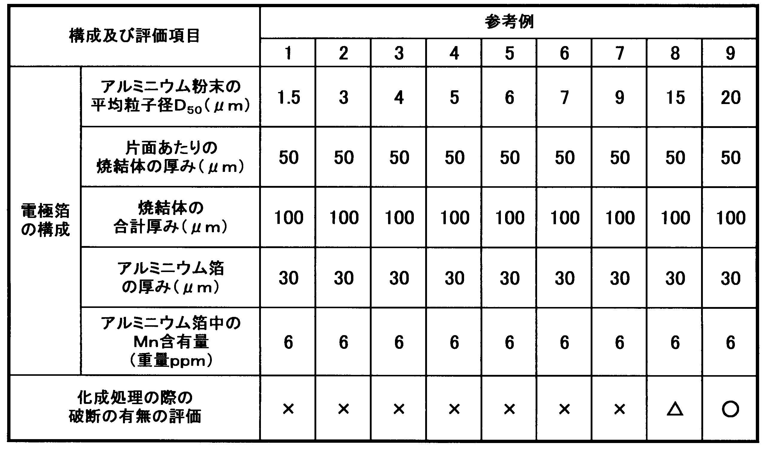

表1の結果から示されるとおり、アルミニウム粉末の平均粒子径(D50)が小さい場合(参考例1~8)、化成処理の際に電極箔に破断が生じることがわかる。コンデンサの静電容量を高くするという観点では、アルミニウム粉末の平均粒子径(D50)が小さいほど有利ではあるが、表1の結果のように化成処理の際に破断が生じてしまうという問題がある。一方で、参考例9のようにアルミニウム粉末の平均粒子径(D50)が大きい場合(20μm)では化成処理の際の破断は見られないが、このような大きな平均粒子径(D50)では、高い静電容量を有する電極箔を得ることができない。以上のように、いずれの参考例においても、化成処理の際に破断が生じず、しかも、高容量である電極箔は得られていないことがわかる。
そこで、以下の実施例及び比較例に示すように、高容量の電極を得ることが可能である平均粒子径(D50)1.5μmのアルミニウム粉末及び特定量のMnを含むアルミニウム箔を用いて電極箔を作製し、化成処理の際の破断の有無について、上記参考例と同様の評価を行った。
(実施例1)
平均粒子径(D50)が1.5μmのアルミニウム粉末60重量部と、エチルセルロース系バインダ40重量部とを混合して混合物を得た後、この混合物を溶剤であるトルエンに分散させることで、固形分濃度が60重量%である塗工液を調製した。
平均粒子径(D50)が1.5μmのアルミニウム粉末60重量部と、エチルセルロース系バインダ40重量部とを混合して混合物を得た後、この混合物を溶剤であるトルエンに分散させることで、固形分濃度が60重量%である塗工液を調製した。
一方、表3に示すように、Mnの含有量が50~21000重量ppmの範囲内で異なる10種類のアルミニウム箔を準備した。いずれのアルミニウム箔も厚みは30μmである。これら10種類のアルミニウム箔のそれぞれに、上記のように調製した塗工液を、アルミニウム箔の片面に、コンマコーターを用いて塗工した後、これを乾燥させて皮膜を形成し、次いで、アルミニウム箔の反対側の面にも同様に塗工液を塗工・乾燥させて皮膜を形成させた。その後、上記のように両面に皮膜が形成された各々のアルミニウム箔を、空気雰囲気中、温度300℃で2時間加熱処理をした後、アルゴンガス雰囲気中にて温度635℃で7時間焼結させた。この焼結によって、アルミニウム箔の両面に焼結体が形成された合計10種類の電極箔を得た。焼結後のアルミニウム粉末層(焼結層)の平均厚みをマイクロメーターで測定したところ、10種類の電極箔いずれも、片面あたり20μmずつの厚みであった(表3参照)。
(実施例2)
表3に示すように、アルミニウム箔の厚みを15μmに変更したこと以外は、実施例1と同様の方法で合計10種類の電極箔を得た。焼結後のアルミニウム粉末層(焼結層)の平均厚みはいずれもの電極箔も実施例1と同じ厚みであった。
表3に示すように、アルミニウム箔の厚みを15μmに変更したこと以外は、実施例1と同様の方法で合計10種類の電極箔を得た。焼結後のアルミニウム粉末層(焼結層)の平均厚みはいずれもの電極箔も実施例1と同じ厚みであった。
(実施例3,4及び6)
焼結後のアルミニウム粉末層(焼結層)の平均厚みが表3に示すような厚みになるように皮膜を形成したこと以外は実施例1と同様の方法で10種類の電極箔を得た。
焼結後のアルミニウム粉末層(焼結層)の平均厚みが表3に示すような厚みになるように皮膜を形成したこと以外は実施例1と同様の方法で10種類の電極箔を得た。
(実施例5)
アルミニウム箔の厚みを80μmとし、かつ、焼結後のアルミニウム粉末層(焼結層)の平均厚みが表3に示すような厚みになるように皮膜を形成したこと以外は実施例1と同様の方法で10種類の電極箔を得た。
アルミニウム箔の厚みを80μmとし、かつ、焼結後のアルミニウム粉末層(焼結層)の平均厚みが表3に示すような厚みになるように皮膜を形成したこと以外は実施例1と同様の方法で10種類の電極箔を得た。
(比較例1)
アルミニウム箔として、Mnの含有量が10重量ppm及び40重量ppmの2種類としたこと以外は実施例1と同様の方法により2種類の電極箔を得た。
アルミニウム箔として、Mnの含有量が10重量ppm及び40重量ppmの2種類としたこと以外は実施例1と同様の方法により2種類の電極箔を得た。
(比較例2)
アルミニウム箔の厚みを15μmに変更したこと以外は、比較例1と同様の方法で合計2種類の電極箔を得た。
アルミニウム箔の厚みを15μmに変更したこと以外は、比較例1と同様の方法で合計2種類の電極箔を得た。
(比較例3,4及び6)
焼結後のアルミニウム粉末層(焼結層)の平均厚みが表4に示すような厚みになるように皮膜を形成したこと以外は比較例1と同様の方法で2種類の電極箔を得た。
焼結後のアルミニウム粉末層(焼結層)の平均厚みが表4に示すような厚みになるように皮膜を形成したこと以外は比較例1と同様の方法で2種類の電極箔を得た。
(比較例5)
アルミニウム箔の厚みを80μmとし、かつ、焼結後のアルミニウム粉末層(焼結層)の平均厚みが表3に示すような厚みになるように皮膜を形成したこと以外は比較例1と同様の方法で2種類の電極箔を得た。
アルミニウム箔の厚みを80μmとし、かつ、焼結後のアルミニウム粉末層(焼結層)の平均厚みが表3に示すような厚みになるように皮膜を形成したこと以外は比較例1と同様の方法で2種類の電極箔を得た。

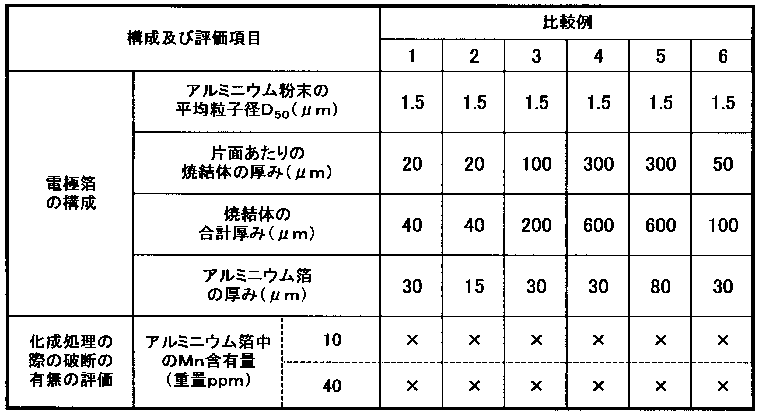
上記実施例及び比較例で得られた電極箔を用い、上記参考例で得られた電極箔と同様の方法で化成処理を行い、同様の評価方法及び評価基準にて、電極箔の化成処理の際の破断の有無を評価した。実施例の電極箔の評価結果は表3に、比較例の電極箔の評価結果は表4に示している。
表3からわかるように、基材であるアルミニウム箔に50重量ppm以上のMnが含まれていることによって、少なくとも、200Vの化成電圧では電極箔が破断する現象は見られなかった。さらには、基材であるアルミニウム箔中のMn濃度が110重量ppm以上であると、700Vの化成電圧において電極箔が破断する可能性が低減することが確認された。さらには、基材であるアルミニウム箔中のMn濃度が150重量ppm以上であると、化成電圧が200Vであっても700Vであっても、どの条件でも電極箔が破断する現象は見られなかった。
以上の実施例1~6からわかるように、Mn含有量が50重量ppmや110重量ppmでは、高い化成電圧では破断するような電極箔が一部見られることがあるが、Mn含有量が150重量ppmを超過すれば高い化成電圧でも電極箔の破断が抑制されることがわかる。しかも、実施例1~6では、平均粒子径(D50)が1.5μmのアルミニウム粉末を用いて作製された電極箔であるため、高静電容量の電極を得ることができるものである。
一方、表4からわかるように、比較例1~5で得られた電極箔では、Mn含有量が50重量ppmに満たないため、化成電圧が200Vであってもすべての電極箔に破断が確認された。
(実験例1)
次に、実施例6と同等の構成の電極箔を用いて作製したコンデンサについて、JIS C 5101-1に準拠する方法により、漏れ電流値(μA/cm2)を測定し、アルミニウム箔中に含まれるMn量と漏れ電流値との関係について調べた。
次に、実施例6と同等の構成の電極箔を用いて作製したコンデンサについて、JIS C 5101-1に準拠する方法により、漏れ電流値(μA/cm2)を測定し、アルミニウム箔中に含まれるMn量と漏れ電流値との関係について調べた。
表5に、漏れ電流の測定結果を示す。
表5からわかるように、Mn濃度が増加するにつれて漏れ電流が大きくなっていることがわかるが、特に、Mn濃度が20000重量ppmを超過すると、漏れ電流が非常に大きくなっている。このような大きな漏れ電流を示す電極箔は、アルミニウム電解コンデンサとしての使用に適さないといえる。Mnが多すぎると、化成処理を施すことによって電極箔の表面に形成された酸化皮膜に欠陥が生じやすくなることから、漏れ電流が非常に大きくなると考えられる。従って、Mnの含有量は、20000重量ppmを超過しないようにする必要がある。

Claims (6)
- アルミニウム及びアルミニウム合金の少なくとも1種の粉末の焼結体と、前記焼結体を支持する基材と、を備えるアルミニウム電解コンデンサ用電極箔であって、
前記基材はMnを50重量ppm以上20000重量ppm未満含むアルミニウム箔であることを特徴とするアルミニウム電解コンデンサ用電極箔。 - 前記基材はMnを110重量ppm以上20000重量ppm未満含むアルミニウム箔である、請求項1に記載のアルミニウム電解コンデンサ用電極箔。
- 前記粉末の平均粒子径(D50)が1.5μm以上20μm以下である、請求項1又は2に記載のアルミニウム電解コンデンサ用電極箔。
- 前記基材の両面に前記焼結体が形成されており、
前記基材の厚さは15μm以上80μm以下であり、
前記焼結体の合計厚みは40μm以上600μm以下である、請求項1から3のいずれか1項に記載のアルミニウム電解コンデンサ用電極箔。 - Mnを50重量ppm以上20000重量ppm未満含むアルミニウム箔の少なくとも一方の表面に、アルミニウム及びアルミニウム合金の少なくとも1種の粉末を含む組成物の皮膜を形成する第1の工程と、前記皮膜を560℃以上660℃以下の温度で焼結する第2の工程とを含み、かつエッチング工程を含まない、ことを特徴とするアルミニウム電解コンデンサ用電極箔の製造方法。
- 前記第1の工程で前記皮膜を前記アルミニウム箔の両面にそれぞれ形成する、請求項5に記載のアルミニウム電解コンデンサ用電極箔の製造方法。
Priority Applications (3)
| Application Number | Priority Date | Filing Date | Title |
|---|---|---|---|
| CN201480070731.1A CN105874549A (zh) | 2013-12-27 | 2014-12-17 | 铝电解电容器用电极箔及其制造方法 |
| US15/106,877 US20170040115A1 (en) | 2013-12-27 | 2014-12-17 | Electrode foil for aluminum electrolytic capacitor and production method for same |
| EP14873930.3A EP3089181B1 (en) | 2013-12-27 | 2014-12-17 | Electrode foil for aluminum electrolytic capacitor and production method for same |
Applications Claiming Priority (2)
| Application Number | Priority Date | Filing Date | Title |
|---|---|---|---|
| JP2013-273418 | 2013-12-27 | ||
| JP2013273418A JP6355920B2 (ja) | 2013-12-27 | 2013-12-27 | アルミニウム電解コンデンサ用電極箔及びその製造方法 |
Publications (1)
| Publication Number | Publication Date |
|---|---|
| WO2015098644A1 true WO2015098644A1 (ja) | 2015-07-02 |
Family
ID=53478508
Family Applications (1)
| Application Number | Title | Priority Date | Filing Date |
|---|---|---|---|
| PCT/JP2014/083381 Ceased WO2015098644A1 (ja) | 2013-12-27 | 2014-12-17 | アルミニウム電解コンデンサ用電極箔及びその製造方法 |
Country Status (6)
| Country | Link |
|---|---|
| US (1) | US20170040115A1 (ja) |
| EP (1) | EP3089181B1 (ja) |
| JP (1) | JP6355920B2 (ja) |
| CN (1) | CN105874549A (ja) |
| TW (1) | TWI651742B (ja) |
| WO (1) | WO2015098644A1 (ja) |
Cited By (4)
| Publication number | Priority date | Publication date | Assignee | Title |
|---|---|---|---|---|
| WO2019073616A1 (ja) | 2017-10-10 | 2019-04-18 | 東洋アルミニウム株式会社 | アルミニウム電解コンデンサ用電極材及びその製造方法 |
| CN113593911A (zh) * | 2021-09-02 | 2021-11-02 | 西安稀有金属材料研究院有限公司 | 一种高比表面积、高比容的烧结阳极材料的制备方法 |
| JPWO2022071221A1 (ja) * | 2020-09-30 | 2022-04-07 | ||
| WO2022168712A1 (ja) * | 2021-02-08 | 2022-08-11 | 東洋アルミニウム株式会社 | アルミニウム電解コンデンサ用電極材及びその製造方法 |
Families Citing this family (13)
| Publication number | Priority date | Publication date | Assignee | Title |
|---|---|---|---|---|
| CN107610935A (zh) * | 2017-08-30 | 2018-01-19 | 丰宾电子(深圳)有限公司 | 铝电解电容器用电极箔制备方法、电极箔及铝电解电容器 |
| CN109036852B (zh) * | 2018-08-13 | 2020-09-18 | 浙江华义瑞东新材料有限公司 | 一种三维多孔铝电极箔及其制备方法 |
| KR102625388B1 (ko) * | 2019-03-01 | 2024-01-17 | 이너 몽골리아 우란차부 동양광 폼드 포일 컴퍼니 리미티드 | 전극 구조체 및 이의 제조 방법 |
| TWI840553B (zh) * | 2019-05-24 | 2024-05-01 | 日商日本輕金屬股份有限公司 | 鋁化成箔、鋁電解電容器用電極及鋁化成箔之製造方法 |
| CN110993348B (zh) * | 2019-12-25 | 2022-03-01 | 西安交通大学 | 一种烧结式铝电解电容器超高压阳极箔及其制备方法 |
| CN112045191B (zh) * | 2020-08-27 | 2021-10-01 | 中南大学 | 一种浆料分散均匀的铝电解电容器阳极箔的烧结方法 |
| CN114523112B (zh) * | 2021-12-30 | 2024-03-22 | 浙江洪量新材科技有限公司 | 一种多孔电极箔及其制备工艺 |
| CN115172061B (zh) * | 2022-08-02 | 2024-01-30 | 南通海星电子股份有限公司 | 一种高介电复合粉末烧结箔的制备方法 |
| CN115172059B (zh) * | 2022-08-09 | 2024-09-24 | 西安稀有金属材料研究院有限公司 | 一种结合气溶胶喷涂法制备铝电解电容器阳极箔的方法 |
| CN115188596A (zh) * | 2022-08-30 | 2022-10-14 | 西安稀有金属材料研究院有限公司 | 一种基于电沉积制备铝电解电容器阳极箔的方法 |
| CN115331966A (zh) * | 2022-08-30 | 2022-11-11 | 西安稀有金属材料研究院有限公司 | 一种基于光固化制备铝电解电容器阳极箔的方法 |
| CN116053043A (zh) * | 2023-02-21 | 2023-05-02 | 西安交通大学 | 铝电解电容器阳极箔及其还原性气氛辅助烧结制备方法 |
| CN116453864B (zh) * | 2023-04-06 | 2024-05-07 | 浙江洪量新材科技有限公司 | 一种高折弯强度的电极箔及其制备工艺 |
Citations (4)
| Publication number | Priority date | Publication date | Assignee | Title |
|---|---|---|---|---|
| JP2008078277A (ja) * | 2006-09-20 | 2008-04-03 | Nippon Light Metal Co Ltd | 電解コンデンサ陰極用アルミニウム合金箔及びそれに用いる合金箔地 |
| JP2008098279A (ja) | 2006-10-10 | 2008-04-24 | Toyo Aluminium Kk | アルミニウム電解コンデンサ用電極材及びその製造方法 |
| JP2009057579A (ja) * | 2007-08-08 | 2009-03-19 | Toyo Aluminium Kk | アルミニウム合金ならびにそれを用いた包装材および電気電子構造部材 |
| JP2009081110A (ja) * | 2007-09-27 | 2009-04-16 | Toyo Aluminium Kk | 集電体用アルミニウム合金箔 |
Family Cites Families (6)
| Publication number | Priority date | Publication date | Assignee | Title |
|---|---|---|---|---|
| US3899723A (en) * | 1971-01-21 | 1975-08-12 | Alusuisse | Cathode foil for electrolytic condensers |
| JP5160839B2 (ja) * | 2006-08-29 | 2013-03-13 | 東洋アルミニウム株式会社 | 集電体用アルミニウム合金箔 |
| JP2009098279A (ja) * | 2007-10-15 | 2009-05-07 | Fuji Xerox Co Ltd | 消耗品管理装置、プログラム及び消耗量推定方法 |
| CN102017034B (zh) * | 2008-04-22 | 2016-01-27 | 东洋铝株式会社 | 用于铝电解电容器的电极材料和制造该电极材料的方法 |
| JP5511630B2 (ja) * | 2009-12-08 | 2014-06-04 | 東洋アルミニウム株式会社 | アルミニウム電解コンデンサ用電極材及びその製造方法 |
| JP5570263B2 (ja) * | 2010-03-24 | 2014-08-13 | 日立エーアイシー株式会社 | 電解コンデンサ用陽極 |
-
2013
- 2013-12-27 JP JP2013273418A patent/JP6355920B2/ja active Active
-
2014
- 2014-12-17 WO PCT/JP2014/083381 patent/WO2015098644A1/ja not_active Ceased
- 2014-12-17 CN CN201480070731.1A patent/CN105874549A/zh active Pending
- 2014-12-17 US US15/106,877 patent/US20170040115A1/en not_active Abandoned
- 2014-12-17 EP EP14873930.3A patent/EP3089181B1/en active Active
- 2014-12-23 TW TW103144960A patent/TWI651742B/zh active
Patent Citations (4)
| Publication number | Priority date | Publication date | Assignee | Title |
|---|---|---|---|---|
| JP2008078277A (ja) * | 2006-09-20 | 2008-04-03 | Nippon Light Metal Co Ltd | 電解コンデンサ陰極用アルミニウム合金箔及びそれに用いる合金箔地 |
| JP2008098279A (ja) | 2006-10-10 | 2008-04-24 | Toyo Aluminium Kk | アルミニウム電解コンデンサ用電極材及びその製造方法 |
| JP2009057579A (ja) * | 2007-08-08 | 2009-03-19 | Toyo Aluminium Kk | アルミニウム合金ならびにそれを用いた包装材および電気電子構造部材 |
| JP2009081110A (ja) * | 2007-09-27 | 2009-04-16 | Toyo Aluminium Kk | 集電体用アルミニウム合金箔 |
Non-Patent Citations (1)
| Title |
|---|
| See also references of EP3089181A4 |
Cited By (11)
| Publication number | Priority date | Publication date | Assignee | Title |
|---|---|---|---|---|
| WO2019073616A1 (ja) | 2017-10-10 | 2019-04-18 | 東洋アルミニウム株式会社 | アルミニウム電解コンデンサ用電極材及びその製造方法 |
| JPWO2022071221A1 (ja) * | 2020-09-30 | 2022-04-07 | ||
| WO2022071221A1 (ja) * | 2020-09-30 | 2022-04-07 | パナソニックIpマネジメント株式会社 | 成膜装置、電解コンデンサ用電極箔の製造方法、および電解コンデンサの製造方法 |
| US12537146B2 (en) | 2020-09-30 | 2026-01-27 | Panasonic Intellectual Property Management Co., Ltd. | Film forming device, manufacturing method of electrode foil for electrolytic capacitor, and manufacturing method for electrolytic capacitor |
| JP7850927B2 (ja) | 2020-09-30 | 2026-04-24 | パナソニックIpマネジメント株式会社 | 成膜装置、電解コンデンサ用電極箔の製造方法、および電解コンデンサの製造方法 |
| WO2022168712A1 (ja) * | 2021-02-08 | 2022-08-11 | 東洋アルミニウム株式会社 | アルミニウム電解コンデンサ用電極材及びその製造方法 |
| JP2022121214A (ja) * | 2021-02-08 | 2022-08-19 | 東洋アルミニウム株式会社 | アルミニウム電解コンデンサ用電極材及びその製造方法 |
| CN116848604A (zh) * | 2021-02-08 | 2023-10-03 | 东洋铝株式会社 | 铝电解电容器用电极材料及其制造方法 |
| US12234559B2 (en) | 2021-02-08 | 2025-02-25 | Toyo Aluminium Kabushiki Kaisha | Electrode material for aluminum electrolytic capacitors and method for producing same |
| JP7635010B2 (ja) | 2021-02-08 | 2025-02-25 | 東洋アルミニウム株式会社 | アルミニウム電解コンデンサ用電極材及びその製造方法 |
| CN113593911A (zh) * | 2021-09-02 | 2021-11-02 | 西安稀有金属材料研究院有限公司 | 一种高比表面积、高比容的烧结阳极材料的制备方法 |
Also Published As
| Publication number | Publication date |
|---|---|
| EP3089181A4 (en) | 2017-05-10 |
| JP2015128112A (ja) | 2015-07-09 |
| EP3089181B1 (en) | 2023-06-07 |
| EP3089181A1 (en) | 2016-11-02 |
| JP6355920B2 (ja) | 2018-07-11 |
| TW201539502A (zh) | 2015-10-16 |
| TWI651742B (zh) | 2019-02-21 |
| US20170040115A1 (en) | 2017-02-09 |
| CN105874549A (zh) | 2016-08-17 |
Similar Documents
| Publication | Publication Date | Title |
|---|---|---|
| JP6355920B2 (ja) | アルミニウム電解コンデンサ用電極箔及びその製造方法 | |
| JP5614960B2 (ja) | 折り曲げ強度が向上した多孔質アルミニウム材料及びその製造方法 | |
| TWI544508B (zh) | Electrode for electrolytic capacitor for electrolysis and method for manufacturing the same | |
| JP6461794B2 (ja) | アルミニウム電解コンデンサ用電極材及びその製造方法 | |
| JP5511630B2 (ja) | アルミニウム電解コンデンサ用電極材及びその製造方法 | |
| TWI544509B (zh) | Electrode for electrolytic capacitor for electrolysis and method for manufacturing the same | |
| JP6001977B2 (ja) | 多孔性アルミニウム体、アルミニウム電解コンデンサ、および多孔性アルミニウム体の製造方法 | |
| JP4958510B2 (ja) | アルミニウム電解コンデンサ用電極材及びその製造方法 | |
| TWI612545B (zh) | 鋁電解電容器用電極材之製造方法及鋁電解電容器用電極材 | |
| JP5618714B2 (ja) | アルミニウム電解コンデンサ用電極材及びその製造方法 | |
| WO2016136804A1 (ja) | アルミニウム電解コンデンサ用電極材及びその製造方法 | |
| JP6073255B2 (ja) | アルミニウム電解コンデンサ用電極材の製造方法 | |
| CN111033657A (zh) | 铝电解电容器用电极材料及其制造方法 | |
| JP7317852B2 (ja) | アルミニウム電解コンデンサ用電極材の製造方法 | |
| JP2018206910A (ja) | アルミニウム電解コンデンサ用電極材及びその製造方法 | |
| TWI673737B (zh) | 鋁電解電容器用電極材及其製造方法 |
Legal Events
| Date | Code | Title | Description |
|---|---|---|---|
| 121 | Ep: the epo has been informed by wipo that ep was designated in this application |
Ref document number: 14873930 Country of ref document: EP Kind code of ref document: A1 |
|
| DPE1 | Request for preliminary examination filed after expiration of 19th month from priority date (pct application filed from 20040101) | ||
| REEP | Request for entry into the european phase |
Ref document number: 2014873930 Country of ref document: EP |
|
| WWE | Wipo information: entry into national phase |
Ref document number: 2014873930 Country of ref document: EP |
|
| WWE | Wipo information: entry into national phase |
Ref document number: 15106877 Country of ref document: US |
|
| NENP | Non-entry into the national phase |
Ref country code: DE |