WO2015098385A1 - ダンパ制御装置 - Google Patents
ダンパ制御装置 Download PDFInfo
- Publication number
- WO2015098385A1 WO2015098385A1 PCT/JP2014/080907 JP2014080907W WO2015098385A1 WO 2015098385 A1 WO2015098385 A1 WO 2015098385A1 JP 2014080907 W JP2014080907 W JP 2014080907W WO 2015098385 A1 WO2015098385 A1 WO 2015098385A1
- Authority
- WO
- WIPO (PCT)
- Prior art keywords
- damper
- vibration level
- damping force
- control device
- vibration
- Prior art date
- Legal status (The legal status is an assumption and is not a legal conclusion. Google has not performed a legal analysis and makes no representation as to the accuracy of the status listed.)
- Ceased
Links
Images



Classifications
-
- B—PERFORMING OPERATIONS; TRANSPORTING
- B60—VEHICLES IN GENERAL
- B60G—VEHICLE SUSPENSION ARRANGEMENTS
- B60G17/00—Resilient suspensions having means for adjusting the spring or vibration-damper characteristics, for regulating the distance between a supporting surface and a sprung part of vehicle or for locking suspension during use to meet varying vehicular or surface conditions, e.g. due to speed or load
- B60G17/06—Characteristics of dampers, e.g. mechanical dampers
- B60G17/08—Characteristics of fluid dampers
-
- B—PERFORMING OPERATIONS; TRANSPORTING
- B60—VEHICLES IN GENERAL
- B60G—VEHICLE SUSPENSION ARRANGEMENTS
- B60G13/00—Resilient suspensions characterised by arrangement, location or type of vibration dampers
- B60G13/02—Resilient suspensions characterised by arrangement, location or type of vibration dampers having dampers dissipating energy, e.g. frictionally
- B60G13/06—Resilient suspensions characterised by arrangement, location or type of vibration dampers having dampers dissipating energy, e.g. frictionally of fluid type
- B60G13/08—Resilient suspensions characterised by arrangement, location or type of vibration dampers having dampers dissipating energy, e.g. frictionally of fluid type hydraulic
-
- B—PERFORMING OPERATIONS; TRANSPORTING
- B60—VEHICLES IN GENERAL
- B60G—VEHICLE SUSPENSION ARRANGEMENTS
- B60G17/00—Resilient suspensions having means for adjusting the spring or vibration-damper characteristics, for regulating the distance between a supporting surface and a sprung part of vehicle or for locking suspension during use to meet varying vehicular or surface conditions, e.g. due to speed or load
- B60G17/015—Resilient suspensions having means for adjusting the spring or vibration-damper characteristics, for regulating the distance between a supporting surface and a sprung part of vehicle or for locking suspension during use to meet varying vehicular or surface conditions, e.g. due to speed or load the regulating means comprising electric or electronic elements
-
- B—PERFORMING OPERATIONS; TRANSPORTING
- B60—VEHICLES IN GENERAL
- B60G—VEHICLE SUSPENSION ARRANGEMENTS
- B60G17/00—Resilient suspensions having means for adjusting the spring or vibration-damper characteristics, for regulating the distance between a supporting surface and a sprung part of vehicle or for locking suspension during use to meet varying vehicular or surface conditions, e.g. due to speed or load
- B60G17/015—Resilient suspensions having means for adjusting the spring or vibration-damper characteristics, for regulating the distance between a supporting surface and a sprung part of vehicle or for locking suspension during use to meet varying vehicular or surface conditions, e.g. due to speed or load the regulating means comprising electric or electronic elements
- B60G17/0152—Resilient suspensions having means for adjusting the spring or vibration-damper characteristics, for regulating the distance between a supporting surface and a sprung part of vehicle or for locking suspension during use to meet varying vehicular or surface conditions, e.g. due to speed or load the regulating means comprising electric or electronic elements characterised by the action on a particular type of suspension unit
-
- B—PERFORMING OPERATIONS; TRANSPORTING
- B60—VEHICLES IN GENERAL
- B60G—VEHICLE SUSPENSION ARRANGEMENTS
- B60G17/00—Resilient suspensions having means for adjusting the spring or vibration-damper characteristics, for regulating the distance between a supporting surface and a sprung part of vehicle or for locking suspension during use to meet varying vehicular or surface conditions, e.g. due to speed or load
- B60G17/015—Resilient suspensions having means for adjusting the spring or vibration-damper characteristics, for regulating the distance between a supporting surface and a sprung part of vehicle or for locking suspension during use to meet varying vehicular or surface conditions, e.g. due to speed or load the regulating means comprising electric or electronic elements
- B60G17/016—Resilient suspensions having means for adjusting the spring or vibration-damper characteristics, for regulating the distance between a supporting surface and a sprung part of vehicle or for locking suspension during use to meet varying vehicular or surface conditions, e.g. due to speed or load the regulating means comprising electric or electronic elements characterised by their responsiveness, when the vehicle is travelling, to specific motion, a specific condition, or driver input
-
- F—MECHANICAL ENGINEERING; LIGHTING; HEATING; WEAPONS; BLASTING
- F16—ENGINEERING ELEMENTS AND UNITS; GENERAL MEASURES FOR PRODUCING AND MAINTAINING EFFECTIVE FUNCTIONING OF MACHINES OR INSTALLATIONS; THERMAL INSULATION IN GENERAL
- F16F—SPRINGS; SHOCK-ABSORBERS; MEANS FOR DAMPING VIBRATION
- F16F15/00—Suppression of vibrations in systems; Means or arrangements for avoiding or reducing out-of-balance forces, e.g. due to motion
- F16F15/02—Suppression of vibrations of non-rotating, e.g. reciprocating systems; Suppression of vibrations of rotating systems by use of members not moving with the rotating systems
-
- F—MECHANICAL ENGINEERING; LIGHTING; HEATING; WEAPONS; BLASTING
- F16—ENGINEERING ELEMENTS AND UNITS; GENERAL MEASURES FOR PRODUCING AND MAINTAINING EFFECTIVE FUNCTIONING OF MACHINES OR INSTALLATIONS; THERMAL INSULATION IN GENERAL
- F16F—SPRINGS; SHOCK-ABSORBERS; MEANS FOR DAMPING VIBRATION
- F16F9/00—Springs, vibration-dampers, shock-absorbers, or similarly-constructed movement-dampers using a fluid or the equivalent as damping medium
- F16F9/32—Details
- F16F9/44—Means on or in the damper for manual or non-automatic adjustment; such means combined with temperature correction
- F16F9/46—Means on or in the damper for manual or non-automatic adjustment; such means combined with temperature correction allowing control from a distance, i.e. location of means for control input being remote from site of valves, e.g. on damper external wall
-
- B—PERFORMING OPERATIONS; TRANSPORTING
- B60—VEHICLES IN GENERAL
- B60G—VEHICLE SUSPENSION ARRANGEMENTS
- B60G2202/00—Indexing codes relating to the type of spring, damper or actuator
- B60G2202/20—Type of damper
- B60G2202/24—Fluid damper
-
- B—PERFORMING OPERATIONS; TRANSPORTING
- B60—VEHICLES IN GENERAL
- B60G—VEHICLE SUSPENSION ARRANGEMENTS
- B60G2400/00—Indexing codes relating to detected, measured or calculated conditions or factors
- B60G2400/90—Other conditions or factors
- B60G2400/91—Frequency
-
- B—PERFORMING OPERATIONS; TRANSPORTING
- B60—VEHICLES IN GENERAL
- B60G—VEHICLE SUSPENSION ARRANGEMENTS
- B60G2500/00—Indexing codes relating to the regulated action or device
- B60G2500/10—Damping action or damper
Definitions
- the present invention relates to a damper control device.
- damper control device for controlling the damping force of the damper interposed between the sprung member and the unsprung member of the vehicle, for example, adjusting the amount of current supplied to the solenoid valve provided in the damper Some adjust the damping force of the damper.
- the damping force characteristics of the damper can be adjusted from soft to hard by supplying a current amount corresponding to the damping force characteristics of the damper to the solenoid.
- a constant current amount corresponding to the soft damping force characteristic is supplied to the solenoid.
- a constant current amount corresponding to the hard damping force is supplied to the solenoid (see, for example, JP11-287281A).
- the sprung member and the unsprung member are supplied with a constant current to the solenoid to cause the damper to exhibit predetermined damping force characteristics. Vibration of the vehicle can be suppressed, and the ride comfort in the vehicle can be improved.
- the damping force characteristics differ depending on the vehicle type. Will change.
- vehicle feeling adjustment work for each vehicle type because vehicle feeling (ride comfort and steering feeling) differs depending on how the current value is calculated when the target damping force outside the range of the map is input. It took a while.
- An object of the present invention is to provide a damper control device capable of reducing the time required for the adjustment operation of the vehicle feeling.
- a damper control device that controls a damping force characteristic with respect to an expansion and contraction speed of a damper interposed between a sprung member and a unsprung member of a vehicle to damp the unsprung member. And a control command for determining the damping force characteristic of the damper based on the vibration level detection unit for detecting the vibration level of the unsprung member and the vibration level detected by the vibration level detection unit. And a control unit that controls force characteristics.
- FIG. 1 is a block diagram of a damper control device according to an embodiment of the present invention.
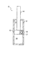
- FIG. 2 is a schematic longitudinal sectional view of the damper.
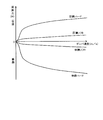
- FIG. 3 is a diagram showing a variable range of damping force characteristics.
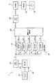
- FIG. 4 is a block diagram of a vibration level detection unit.
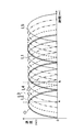
- FIG. 5 is a diagram showing the waveform of the level calculation signal.
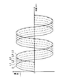
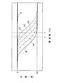
- FIG. 6 is a diagram showing the frequency phase characteristic of the level calculation signal.
- FIG. 7 is a diagram showing the waveform of the absolute value of the level calculation signal.
- FIG. 8 is a diagram showing the waveform of the absolute value of the level calculation signal with respect to the input of the original signal different in frequency.
- FIG. 9 is a diagram showing a waveform of vibration level.
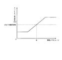
- FIG. 10 is a diagram showing the relationship between the cutoff frequency of the ripple removal filter and the vibration level.
- the damper control device E is configured to control the damping force in the damper D interposed between the sprung member B and the unsprung member W of the vehicle. .
- the damper control device E has a vibration level detection unit 1 that detects a vibration level r that is a magnitude of vibration of the unsprung member W, and an expansion and contraction speed of the damper D based on the vibration level r detected by the vibration level detection unit 1. And a controller 2 for controlling a damping force characteristic which is a characteristic of the damping force.
- the damper D is interposed between the sprung member B and the unsprung member W of the vehicle in parallel with the suspension spring VS in this embodiment.
- the sprung member B is elastically supported by a suspension spring VS.
- the unsprung member W includes a wheel and a link that are pivotally attached to the sprung member B, which is a vehicle body.
- the damper D is a cylinder 12, a piston 13 slidably inserted in the cylinder 12, and a piston rod movably inserted in the cylinder 12 and coupled to the piston 13. 14, pressure chambers 15 and 16 divided by the piston 13 in the cylinder 12, a damping force adjustment passage 17 communicating the pressure chamber 15 with the pressure chamber 16, and the flow of working fluid passing through the damping force adjustment passage 17 And a proportional solenoid valve 18 as a damping force adjustment unit that gives resistance to the fluid pressure damper.
- the damper D resists the flow of the working fluid with the proportional solenoid valve 18 when the working fluid filled in the pressure chambers 15 and 16 passes the damping force adjustment passage 17 in response to the extension and contraction operation. Demonstrate the damping force to suppress. Thereby, the damper D is configured to suppress relative movement between the sprung member B and the unsprung member W.
- the cylinder 12 is filled with a fluid such as hydraulic oil, water, an aqueous solution or the like as a working fluid.
- the proportional solenoid valve 18 changes the damping force characteristic of the damper D in accordance with the magnitude of the current supplied by the control command supplied from the control unit 2, for example, as shown in FIG.
- the force characteristics can be adjusted from soft to hard.
- damping force characteristics of the damper D are achieved.
- the proportional solenoid valve 18 controls, for example, a valve body (not shown) that makes the flow passage area of the damping force adjustment passage 17 variable, and adjusts the flow passage area of the damping force adjustment passage 17 by driving the valve body.
- a solenoid capable of The valve body may be driven by an actuator other than a solenoid.
- the flow passage area of the damping force adjustment passage 17 is adjusted by increasing or decreasing the amount of current supplied to the actuator. Thereby, the resistance given to the working fluid flowing through the damping force adjustment passage 17 can be changed to adjust the damping force generated by the damper D.
- the damping force adjustment unit may be other than the proportional solenoid valve 18.
- the damping force adjustment unit is a device that applies a magnetic field to the damping force adjustment passage 17.
- the magnitude of the magnetic field is adjusted by the amount of current supplied from the damper control device E.
- the resistance given to the flow of the magnetorheological fluid passing through the damping force adjustment passage 17 is changed to make the damping force of the damper D variable.
- the damping force adjustment unit is a device capable of causing an electric field to be applied to the damping force adjustment passage 17.
- the magnitude of the electric field is adjusted by the voltage applied from the damper control device E.
- the resistance given to the electro-rheological fluid flowing through the damping force adjustment passage 17 is changed to make the damping force of the damper D variable.
- the damper D when the working fluid is a liquid and the damper D is a single rod type damper, the damper D includes a gas chamber or a reservoir to compensate for the volume in and out of the piston rod 14 in the cylinder 12.
- the working fluid when the working fluid is a gas, the gas chamber or the reservoir may not be provided.
- a damping force adjustment unit may be provided to resist the flow of the working fluid.
- the damper D may be an electromagnetic damper that exerts a damping force by an electromagnetic force.
- the electromagnetic damper includes, for example, a motor and a motion conversion mechanism that converts rotational motion of the motor into linear motion, or is a linear motor.
- the damping force adjustment unit may be a motor or a motor drive device that adjusts the current flowing through the linear motor.
- the vibration level detection unit 1 includes a stroke sensor 21 that detects a stroke displacement of the damper D and a sensor that includes a differentiator 22 that obtains a damper speed from the damper displacement detected by the stroke sensor 21.
- the signal generation unit 24 generates two or more level calculation signals whose phases are different from each other, the maximum value among the absolute values of the original signal O and each level calculation signal, and the vibration level with the maximum value as the vibration level r
- the signal generation unit 24 generates five level calculation signals L1 to L5.
- the stroke sensor 21 is interposed between the sprung member B and the unsprung member W, and detects the stroke displacement of the damper D.
- the stroke sensor 21 may be provided integrally with the damper D.
- the differentiator 22 differentiates the stroke displacement to obtain the damper velocity, and outputs the damper velocity.
- the band-pass filter 23 extracts the vibration component of the unsprung resonance frequency band from the damper speed and outputs it as an original signal O.
- the damper speed obtained by processing the damper speed by the band-pass filter 23, that is, the damper speed after filtering by the band-pass filter 23, rises with respect to the damper speed output by the differentiator 22, and the initial phase is delayed.
- the signal generation unit 24 is configured such that phase change filters F1 to F5 are provided in parallel, and the original signal O is filtered by the phase change filters F1 to F5.
- the phase change filters may be provided corresponding to the number of level calculation signals. In this case, five phase change filters may be provided corresponding to the level calculation signals L1 to L5.
- the transfer function G (s) of the phase change filters F1 to F5 is set by the following equation (1).
- O (s) represents the Laplace transform amount of the original signal O
- s represents the Laplace operator
- the frequency is set.
- the signal generation unit 24 filters the original signal O with the phase change filter F4 having the transfer function G (s) set by inputting ⁇ 4 in the frequency,
- the level calculation signal L4 is obtained from the original signal O.
- the amplitude is the same for the original signal O of a certain frequency x. That is, it is possible to easily obtain five level calculation signals L1 to L5 which are different only in phase from each other.
- phase difference between the original signal O and the level calculation signal L1 and the phase difference between the level calculation signals L1 to L4 are equal, the phase difference between the level calculation signal L4 and the level calculation signal L5 is the original.
- the phase difference between the signal O and the level calculation signal L1 and the phase difference between the level calculation signals L1 to L4 are different. This is a characteristic that the frequency phase characteristics of the level calculation signals L1 to L4 change in the range from the upper limit of 0 degree to the lower limit of -180 degrees, as shown in FIG. It is because it is limited.
- the phases of the level calculation signals L1 to L5 are 0 degrees or near 0 degrees when the frequency of the original signal O is extremely low, or -180 degrees when the frequency of the original signal O is extremely high. It becomes near -180 degrees. Therefore, as shown in FIG. 5, in the level calculation signals L1 to L4, the phase differences are arranged at equal intervals, and in the level calculation signal L5, the phase becomes close to -180 degrees and the next level calculation signal is generated. The phase difference with L4 is reduced.
- the transfer function G (s) of the phase change filters F1 to F5 may be set by the following equation (2).
- O (s) represents the Laplace transform amount of the original signal O
- s represents the Laplace operator
- the frequency is set.
- the phase change filters F1 to F5 can also be second-order low-pass filters.
- the transfer function G (s) of the phase change filters F1 to F5 may be set by the following equation (3).
- O (s) represents the Laplace transform amount of the original signal O
- s indicates the Laplace operator
- ⁇ indicates the decay rate
- the frequency is shown, and different cutoff frequencies are set from ⁇ 1 to ⁇ 5.
- phase change filters F1 to F5 When a low pass filter is used for phase change filters F1 to F5, the phases of level calculation signals L1 to L5 can be delayed with respect to original signal O. With a high pass filter, level calculation signals L1 to L5 for original signal O can be obtained. The phase of L5 can be advanced. Therefore, it is also possible to use a high pass filter as part of the phase change filters F1 to F5 and use a low pass filter as the rest of the phase change filters F1 to F5.
- the signal generation unit 24 obtains level calculation signals L1 to L5 having different phases from the original signal O. Therefore, signals delayed from the original signal O by a prescribed time may be generated as the level calculation signals L1 to L5 without using the above-mentioned filter processing.
- the vibration level calculator 25 obtains the maximum value among the signals obtained by subjecting the original signal O and the level calculation signals L1 to L5 to absolute value processing.
- the waveforms of the original signal O and the level calculation signals L1 to L5 after the absolute value processing are calculated as shown in FIG.
- a portion having a negative value is folded back to the positive side around the time axis.
- the original signal O and the level calculation signals L1 to L5 Since the absolute values of the original signal O and the level calculation signals L1 to L5 are out of phase with each other, the original signal O and the level calculation signals L1 to L5 subjected to the absolute value processing do not require processing.
- the respective waveforms in the level calculation signals L1 to L5 are shifted in time.
- the maximum value of the original signal O and the level calculation signals L1 to L5 after the absolute value processing is equal to the maximum amplitude of the original signal O or The value approximates to the maximum amplitude.
- the maximum value of original signal O and level calculation signals L1 to L5 after absolute value processing at time a is the maximum value of level calculation signal L2. Further, the maximum values of the original signal O and the level calculation signals L1 to L5 after the absolute value processing at the time b become values approximate to the value of the maximum amplitude of the original signal O.
- the maximum amplitudes of the level calculation signals L1 to L5 are equal to the maximum amplitude at the speed of the original signal O. Also, since the maximum amplitude of the original signal O is a component of the unsprung resonance frequency band of the expansion / contraction speed of the damper D and the original signal O is approximately equal to the speed of the unsprung member W, It is equal to the vibration level r of the unsprung member W. That is, the maximum value when one cycle of the original signal O is obtained is the vibration level r of the unsprung member W.
- the vibration level of the unsprung member W can not be determined timely, and if the frequency of the vibration of the unsprung member W changes, the original signal O Since the time required for the cycle changes, the maximum amplitude can not be obtained.
- the original signal after absolute value processing is calculated at the time of calculating the vibration level r. It can be expected that either O or each of the level calculation signals L1 to L5 has a maximum value or a value close to the maximum value. Therefore, by obtaining the maximum value among the original signal O subjected to the absolute value processing and each of the level calculation signals L1 to L5 and using it as the vibration level r, the vibration level r may be the value of the maximum amplitude of the original signal O itself or It can be obtained as an approximation to
- the vibration level r becomes the value of the maximum amplitude of the original signal O or a value close to this. That is, even if the frequency of the original signal O changes, a value close to the value of the maximum amplitude of the original signal O can be obtained as the vibration level r.
- the phase difference between the original signal O and the level calculation signal L1 is the phase difference between the level calculation signals L1 to L5. It is different from This is because, as shown in FIG. 6, although the phase of the original signal O is constant at 0 degrees, the phase of the level calculation signal L1 is limited at an upper limit of 0 degrees as the frequency decreases. As a result, the phase of the level calculation signal L1 approaches 0 degrees, and the phase difference with the original signal O decreases.
- the phase difference between the level calculation signal L1 and the adjacent level calculation signal L2 also decreases.
- the frequency decreases, it is possible to obtain a value approximate to the value of the maximum amplitude of the original signal O as the vibration level r by the level calculation signals L2 to L5 having equal phase differences.
- the vibration level detection unit 1 even if the frequency of the original signal O changes, the value of the maximum amplitude of the original signal O or a value approximate to the value of the original signal O can be detected in real time and timely. It can be determined as Therefore, the vibration level r can be accurately obtained for signals in a wide frequency band.
- the original signal O is a speed that is vibration information of the unsprung member W. Therefore, by detecting the vibration level r as described above, the magnitude (vibration level) of the vibration of the unsprung member W can be detected timely and in real time.
- the vibration level r obtained in this way has a small time delay with respect to the vibration of the unsprung member W, so it can sufficiently withstand, for example, the use for suppressing and controlling the vibration of the vehicle.
- the vibration level r of the unsprung member W is obtained using the original signal O and the level calculation signals L1 to L5, but the frequency band where the vibration level r of the unsprung member W is to be obtained from the original signal O
- the vibration level r may be obtained in the vibration level calculator 25 by using only the level calculation signal without using the original signal O.
- the damper velocity is obtained from the stroke displacement of the damper D detected by the stroke sensor 21, and then the frequency component of the unsprung resonance frequency band of the damper velocity is extracted.
- the vibration level r is detected.
- the vibration information of the sprung member B necessarily includes the influence of the vibration of the unsprung member W.
- the waveform of the vibration level of the spring top member B approximates the waveform of the vibration level r of the unsprung member W. Therefore, if the vibration information of the sprung member B, that is, the vertical acceleration, the vertical velocity, or the displacement of the sprung member B is detected, and the vibration level is determined using this, the unsprung member W Can be substituted as the vibration level r of.
- detecting the vibration level r of the unsprung member W also includes substituting the vibration level obtained from the vibration information of the sprung member B as the vibration level r of the unsprung member W.
- phase change filters F1 to F5 process the original signal O in parallel to obtain the level calculation signals L1 to L5.
- the phase change filters F1 to F5 can be arranged in series.
- the original signal O is processed by the phase change filter F1 to obtain the level calculation signal L1
- the level calculation signal L1 is processed by the phase change filter F2 to obtain the level calculation signal L2
- the level calculation signal processed by the immediately preceding phase change filter is processed by the immediately subsequent phase change filter to obtain a level calculation signal.
- the frequency phase characteristic of the level calculation signal changes in the range from the upper limit of 0 degree to the lower limit of -180 degree, approaches 0 degree when the frequency decreases, and -180 when the frequency increases. It's getting closer to the degree. Therefore, for high frequency x, the phases of the original signal O processed by the phase change filters F1 to F5 and the level calculation signals L1 to L4 are equally spaced, and the maximum amplitude of the original signal O or a value approximated thereto is equal. Vibration level r can be obtained. Further, for the low frequency y, the phases of the level calculation signals L1 to L5 are equally spaced, and it is possible to obtain the maximum amplitude of the original signal O or the vibration level r having a value close to this.
- the vibration level r can be accurately detected with respect to the original signal O from the high frequency frequency x to the low frequency frequency y.
- the phase change filters F1 to F5 contribute to the detection of the vibration level r with respect to the original signal O of the frequency y.
- the frequency of the original signal O changes the phase change filter that contributes to the detection of the vibration level r.
- the original signal when using the original signal O together with the level calculation signal, the original signal within the lower limit to the upper limit of the frequency band
- O and at least two or more level calculation signals be dispersed with equal phase difference within a range of 180 degrees.
- the vibration level r is obtained using only the level calculation signal, it is preferable that at least three or more level calculation signals be dispersed at equal intervals within the range of 180 degrees. Therefore, the number of installed filters for generating the level calculation signal may be determined according to the number of generation of the level calculation signal.
- the original signal O and the level calculation signals L1 to L5 contributing to detection of the vibration level r are dispersed with an equal phase difference of 60 degrees or less within the range of 180 degrees.
- the signal generation unit 24 when the signal generation unit 24 generates the level calculation signals L1 to L5, the vibration level r can be detected for signals in a wide frequency band, and the accuracy is also improved.
- the signal generation unit 24 determines that the level calculation signals L1 to L5 contributing to the detection of the vibration level r are 60 degrees within the range of 180 degrees. If generation is performed so as to be distributed with equal phase differences equal to or less than a degree, the vibration level r can be detected for signals in a wide frequency band, and the accuracy is also improved.
- the phase difference between the level calculation signals is small.
- the absolute values of the calculated signal in addition to using the maximum value as the vibration level r, the second or third largest value as the vibration level r, or the average value of the maximum value and the second largest value as the vibration level r There is no problem in practical use.
- the vibration level r is expressed as the third largest value among the absolute values of the level calculation signal as the vibration level r, It never falls below 0.9 times the wave height of the original signal O of the object. Therefore, a good vibration level r can be obtained. Even in this case, the maximum value among the absolute values of the level calculation signal is the value closest to the actual vibration level r. For this reason, it is preferable to determine the maximum value as the vibration level r.
- the vibration level r of the unsprung member W determined as described above is processed by the ripple removal filter 26.
- the ripple removal filter 26 is a low pass filter provided for the purpose of removing high frequency components included in the vibration level r. By filtering the vibration level r with the ripple removal filter 26, it is possible to obtain the vibration level r that is delayed in phase from the actual vibration level of the unsprung member W.
- the damper speed is filtered by the band-pass filter 23 to delay the initial rising phase, obtain the vibration level r from the damper speed delayed from the initial phase, and filter the vibration level r with the ripple removal filter 26. From the vibration level of the unsprung member W, the vibration level r which is totally delayed in phase can be obtained.
- the control unit 2 obtains a control command to be given to the drive unit 19 from the vibration level r obtained as described above. Then, a control command is output to the drive unit 19 that drives the proportional solenoid valve 18.
- the drive unit 19 includes, for example, a PWM circuit or the like, and supplies the current I to the proportional solenoid valve 18 according to the control command obtained by the control unit 2.
- control unit 2 multiplies the vibration level r by a proportional gain to obtain a control command, and as shown in FIG. 4 in order to output a current as the control command from the drive unit 19 to the proportional solenoid valve 18
- the control command obtained is input to the drive unit 19.
- the damping force adjustment unit is the proportional solenoid valve 18
- the control command output to the drive unit 19 is the current command.
- the proportional solenoid valve 18 receives the supply of current from the drive unit 19 to adjust the damping force characteristic of the damper D. Then, the damper D exerts a damping force corresponding to the damper speed at that time. Thus, the damping force of the damper D is controlled by the damper control device E.
- the damper control device E obtains the vibration level r of the unsprung member W, generates a control command from the vibration level r, applies a current to the proportional solenoid valve 18 according to the control command, and Control the damping force.
- the vibration level r detected by the vibration level detection unit 1 is delayed in phase with respect to the actual vibration level of the unsprung member W. For this reason, the control command also causes a time delay with respect to the actual vibration level of the unsprung member W.
- the vertical velocity of the unsprung member W is as shown by a solid line in FIG.
- the time on the horizontal axis in FIG. 9 represents the time after the wheel contacts the projection.
- the vertical axis represents the speed of the unsprung member W and the magnitude of the vibration level.
- the vertical velocity of the unsprung member W in the situation where the vehicle passes through the projections of the road surface increases after the wheel contacts the projections.
- the actual vibration level of the unsprung member W also shows a large value immediately after the unsprung member W is pushed up by the projection, as shown by a broken line in FIG.
- the vibration level r detected by the vibration level detection unit 1 is to filter the damper speed used when obtaining the vibration level r with the band-pass filter 23 and filter the vibration level with the ripple removal filter 26.
- the phase is generally delayed from the actual vibration level of the unsprung member W. For this reason, the vibration level r has a slow rise, as indicated by the one-dot chain line in FIG.
- the spring upper member tries to go straight even when the wheel contacts the protrusion, so that the damper D is contracted and the unsprung member W is pushed up sharply, and the spring is unsprung.
- the actual vibration level of the member W is increased.
- the damping force generated by the damper D is suppressed low by the vibration level r delayed with respect to the actual vibration level.
- the damper D controlled by the damper control device E when the vehicle passes through the projections of the road surface, the vibration level r is small immediately after the wheels come in contact with the projections, and the damper D The damping force that suppresses this against contraction is small. Thereafter, when the damper D changes from the contraction operation to the extension operation, the value of the vibration level r increases. As a result, the damper D exerts a large damping force so as to prevent the expansion, and suppresses the vibration of the unsprung member W.
- the vibration level r is small immediately after the wheel enters the recess, and the damping force that suppresses the rapid expansion of the damper D is small. Thereafter, when the damper D changes from the extension operation to the contraction operation, the value of the vibration level r increases. Thus, the damper D exerts a large damping force so as to prevent the contraction, and suppresses the vibration of the unsprung member W.
- the damping force is maintained low with respect to the contraction of the damper D when riding on a protrusion of the road surface or the extension of the damper D when entering into the recess.
- the increase of the acceleration peak value of the sprung member B can be prevented.
- contraction after the expansion-contraction direction inversion of the damper D a large damping force can be exhibited and the flap of the unsprung member W can be suppressed.
- the damper control device E it is possible to enhance the insulation of the transmission of vibration from the unsprung member W to the sprung member B when the vehicle climbs over the protrusions and recesses of the road surface, and the unsprung member W rattles. Since the unsprung member W can be quickly damped by suppressing the friction force, the ride comfort of the vehicle can be improved when crossing over the projections and the depressions of the road surface.
- the damping force of the damper D can be controlled only by directly producing a control command corresponding to the current command by multiplying the vibration level r by the proportional gain, not the damping force command. it can. That is, when obtaining the control command from the vibration level r, the map calculation using the current command calculation map showing the relationship between the damping force, the current supplied to the proportional solenoid valve 18 and the damper speed is not performed or other complicated calculations are performed. Therefore, the control command can be easily obtained.
- the current command calculation map must be prepared for each vehicle type because the damping force characteristics of the damper D change as the vehicle changes. For this reason, it is necessary to investigate and map the relationship between the current supplied to the valve for adjusting the damping force and the damping force characteristic and the damper speed each time the vehicle type changes.
- the control command for adjusting the damping force characteristic is determined without obtaining the current command calculation map, the number of mapping steps as described above can be reduced. Therefore, according to the present embodiment, it is not necessary to use a map for calculating the current command that changes for each vehicle type, and it is not necessary to spend time on the adjustment operation of the vehicle feeling. Thus, it is possible to reduce the time taken to adjust the vehicle feeling.
- the frequency band in which the unsprung member W resonates is a high frequency. For this reason, since the stroke amount of the damper D due to the resonance of the unsprung member W is extremely small, the deformation of the mount becomes relatively large. And in order to detect damper speed, the method of detecting using a stroke sensor which detects relative displacement of spring top member B and unsprung member W, and an acceleration sensor attached to both is generally taken.
- the target damping force to be output to the damper D is determined, and the amount of current to be applied to a valve or the like that adjusts the damping force of the damper D is determined from the target damping force and the damper speed. It is conceivable. However, in this case, since the deviation between the actual damper speed of the damper D and the damper speed detected by the sensor is large, even if it is intended to suppress the resonance of the unsprung member W, the damper D has a damping force according to the target damping force. In some cases, the ride comfort of the vehicle may be deteriorated.
- a level calculation signal is generated to set the maximum value as the vibration level r, but any of the displacement, velocity and acceleration of the unsprung member W may be used.
- the value of the maximum amplitude of the selected information may be adopted as the vibration level. Therefore, any one of displacement, velocity, and acceleration may be selected, and the selected information and the length of the combined vector of the integral value or the derivative value of the selected information may be obtained as the vibration level.
- the vibration information of the spring top member B can be detected to obtain the vibration level, and this can be used as the vibration level r of the unsprung member W.
- the vibration information of the unsprung member W superimposed on the vibration information of the sprung member B from the vibration information of the sprung member B may be extracted by a band-pass filter to obtain the vibration level r.
- the band filter 23 for extracting the vibration of the unsprung member W may not be used. In this case, processing may be separately performed so that the vibration level r is delayed in phase with respect to the actual vibration level. Further, instead of delaying the phase of the vibration level r by a filter, processing of delaying in time may be performed.
- the phase delay of the detected vibration level r with respect to the actual vibration level also includes the temporal delay of the detected vibration level r with respect to the actual vibration level.
- the rear wheel of the vehicle passes through the protrusion and the recess through which the front wheel passes.
- the time for the rear wheel to pass through the same protrusion or recess is estimated from the vehicle speed, and when the rear wheel approaches the protrusion or recess
- the feedforward control may be performed to delay and use the command of.
- control unit 2 obtains the control command by multiplying the vibration level r by the proportional gain, but the present invention is not limited to this.
- a map calculation may be performed using an arbitrary map from the vibration level r to obtain a control command, or a control command may be obtained using an equation having the vibration level r as a parameter.
- the proportional solenoid valve 18 is used to control the damper D.
- damping force characteristics of the expansion pressure of the damper D orifice, expansion side damping force and compression side damping force (Characteristics characterized by an expansion ratio, etc.) which is a ratio of
- the resonance of the unsprung member W can be suppressed without deteriorating the ride quality in the vehicle. That is, only when the unsprung member W vibrates, a current corresponding to the vibration level r is applied to the solenoid to suppress the resonance, so that the ride comfort in the vehicle is not deteriorated.
- the control command in the control unit 2 is the current command.
- the control command may be a command suitable for the damping force adjustment unit. Therefore, when the damping force adjustment unit is configured with a rotary valve and a stepping motor other than the proportional solenoid valve 18, for example, the control command may be the number of times of pulse generation. Further, when the working fluid in the damper D is an electro-rheological fluid, the damping force adjusting unit generates an electric field, so the control command may be a voltage command.
- the damper control device E includes an A / D converter for taking in a signal output from the stroke sensor 21, vibration level detection, and calculation of the current value I.
- a storage device such as a ROM (Read Only Memory) in which a program used for necessary processing is stored, an arithmetic device such as a CPU (Central Processing Unit) that executes processing based on the program, and a storage area for the CPU And a storage device such as a random access memory (RAM).
- ROM Read Only Memory
- CPU Central Processing Unit
- RAM random access memory
- the ripple removal filter 26 by providing the ripple removal filter 26, high frequency components included in the vibration level r are removed.
- the cutoff frequency in the ripple removal filter 26 can also be made variable by the magnitude of the value of the vibration level r.
- the cutoff frequency is equal to or lower than the unsprung resonance frequency which is the resonance frequency of the unsprung member W Make it
- the vibration level r When the vibration level r is processed by the ripple removal filter 26 having a constant cutoff frequency, if the vibration level r changes frequently in the region where the vibration level r is small, the signal component of the vibration information of the unsprung member W in the vertical direction On the other hand, the effects of sensor noise and other vibration components become relatively large. Therefore, the so-called S / N ratio is deteriorated, and the calculation accuracy of the vibration level r is lowered. Therefore, in fact, the damping force characteristic can not be set according to the vibration condition of the unsprung member W, and the sprung member B may shake slightly.
- the ripple removal filter 26 processes even if it fluctuates in the region where the vibration level r is small.
- the vibration level r is smoothed without fluctuation and takes a substantially constant value.
- the damper control device E outputs a substantially constant control command, and the damping force output by the damper D is stabilized to further improve the ride comfort in the vehicle.
- control command (damping force) is set by gradually changing from the lower limit value to the upper limit value of the cutoff frequency according to the vibration level r. Sudden changes in characteristics can be suppressed.
- the threshold R can be arbitrarily set to be suitable for a real vehicle.
- the vibration level r of the unsprung member W when it is obtained by scaling the speed, it may be set to about 0.1 m / s.
- the threshold R may be set to be suitable for a real vehicle.
- the vibration level r when the vibration level r becomes smaller than the threshold value R, the same effect can be obtained by setting the control command to a certain constant value instead of making the cutoff frequency of the ripple removal filter 26 variable. be able to. Therefore, in such a situation, in addition to setting the control command to a constant value, the vibration level r may be subjected to moving average processing to make it difficult to change, or the unsprung resonance frequency or a frequency twice the unsprung resonance frequency. A notch filter may be inserted only in the band to remove fluctuation components from the vibration level r.
Landscapes
- Engineering & Computer Science (AREA)
- Mechanical Engineering (AREA)
- General Engineering & Computer Science (AREA)
- Physics & Mathematics (AREA)
- Acoustics & Sound (AREA)
- Aviation & Aerospace Engineering (AREA)
- Vehicle Body Suspensions (AREA)
- Vibration Prevention Devices (AREA)
- Fluid-Damping Devices (AREA)
Abstract
Description



Claims (6)
- 車両のばね上部材とばね下部材との間に介装されるダンパにおける伸縮速度に対する減衰力特性を制御して前記ばね下部材を制振するダンパ制御装置であって、
前記ばね下部材の振動レベルを検知する振動レベル検知部と、
前記振動レベル検知部で検知した前記振動レベルに基づいて前記ダンパの前記減衰力特性を決定する制御指令を求めて前記減衰力特性を制御する制御部と、
を備えるダンパ制御装置。 - 請求項1に記載のダンパ制御装置であって、
前記振動レベル検知部は、前記ばね上部材の上下方向加速度、上下方向速度、及び上下方向変位のいずれかに基づいて、前記ばね下部材の前記振動レベルを検知するダンパ制御装置。 - 請求項2に記載のダンパ制御装置であって、
前記制御部は、前記振動レベルに比例する前記制御指令を求めるダンパ制御装置。 - 請求項1に記載のダンパ制御装置であって、
前記振動レベル検知部は、前記ばね下部材の実際の振動レベルに対して位相が遅れた前記振動レベルを検知するダンパ制御装置。 - 請求項1に記載のダンパ制御装置であって、
前記振動レベル検知部は、前記振動レベルが所定の閾値よりも小さい場合は、前記ばね下部材の共振周波数以上の周波数成分を取り除いて前記振動レベルを検知するダンパ制御装置。 - 請求項1に記載のダンパ制御装置であって、
前記ダンパは、
シリンダと、
前記シリンダ内に摺動自在に挿入されるピストンと、
前記シリンダ内に前記ピストンで区画される伸側室及び圧側室と、
伸長時と収縮時との両方で作動流体の通過を許容するとともに通過する作動流体の流れに抵抗を与える減衰力調整通路と、
前記減衰力調整通路に設けられて前記ダンパの前記減衰力特性を変更する比例ソレノイドバルブと
を備え、
前記制御部は、前記比例ソレノイドバルブに前記制御指令を与えて前記減衰力特性を制御するダンパ制御装置。
Priority Applications (2)
| Application Number | Priority Date | Filing Date | Title |
|---|---|---|---|
| DE112014003793.1T DE112014003793T5 (de) | 2013-12-24 | 2014-11-21 | Dämpfersteuereinrichtung |
| US15/027,720 US20160243916A1 (en) | 2013-12-24 | 2014-11-21 | Damper control device |
Applications Claiming Priority (2)
| Application Number | Priority Date | Filing Date | Title |
|---|---|---|---|
| JP2013265226A JP6031025B2 (ja) | 2013-12-24 | 2013-12-24 | ダンパ制御装置 |
| JP2013-265226 | 2013-12-24 |
Publications (1)
| Publication Number | Publication Date |
|---|---|
| WO2015098385A1 true WO2015098385A1 (ja) | 2015-07-02 |
Family
ID=53478257
Family Applications (1)
| Application Number | Title | Priority Date | Filing Date |
|---|---|---|---|
| PCT/JP2014/080907 Ceased WO2015098385A1 (ja) | 2013-12-24 | 2014-11-21 | ダンパ制御装置 |
Country Status (4)
| Country | Link |
|---|---|
| US (1) | US20160243916A1 (ja) |
| JP (1) | JP6031025B2 (ja) |
| DE (1) | DE112014003793T5 (ja) |
| WO (1) | WO2015098385A1 (ja) |
Families Citing this family (8)
| Publication number | Priority date | Publication date | Assignee | Title |
|---|---|---|---|---|
| WO2015182168A1 (ja) * | 2014-05-28 | 2015-12-03 | 株式会社ショーワ | 減衰力可変機構の検査方法、検査システム及び圧力緩衝装置の検査方法 |
| KR102429549B1 (ko) * | 2015-05-18 | 2022-08-05 | 주식회사 만도 | 전자제어 현가장치 및 그의 감쇠력 제어 방법 |
| US10754358B2 (en) * | 2015-09-28 | 2020-08-25 | Koninklijke Philips N.V. | Methods and systems for controlling gas flow using a proportional flow valve |
| JP6673073B2 (ja) * | 2016-07-19 | 2020-03-25 | 日本製鉄株式会社 | 鉄道車両用ヨーダンパ装置 |
| CN108466903B (zh) * | 2018-05-28 | 2024-01-09 | 广州广日电梯工业有限公司 | 一种电梯承重梁自调节减震装置及方法 |
| CN113525007A (zh) * | 2020-04-17 | 2021-10-22 | 陕西重型汽车有限公司 | 一种汽车智能悬架系统 |
| KR20250084497A (ko) * | 2023-12-04 | 2025-06-11 | 에이치엘만도 주식회사 | 자동차 서스펜션의 노이즈 저감 시스템 및 노이즈 저감 방법 |
| KR102942620B1 (ko) * | 2025-12-16 | 2026-03-20 | 국립군산대학교산학협력단 | 해양 부유 구조물 탑재 원자로의 진동 절연 시스템 |
Citations (4)
| Publication number | Priority date | Publication date | Assignee | Title |
|---|---|---|---|---|
| JPH07276952A (ja) * | 1994-04-08 | 1995-10-24 | Nissan Motor Co Ltd | 電気粘性流体を用いた減衰力可変ショックアブソーバの制御方法及び制御装置 |
| JP2010163099A (ja) * | 2009-01-16 | 2010-07-29 | Toyota Motor Corp | タイヤばね定数推定方法およびタイヤのばね定数を推定可能な車両用サスペンションシステム |
| JP2011225040A (ja) * | 2010-04-16 | 2011-11-10 | Nissan Motor Co Ltd | サスペンション制御装置 |
| JP2013159204A (ja) * | 2012-02-03 | 2013-08-19 | Kyb Co Ltd | サスペンション装置 |
Family Cites Families (1)
| Publication number | Priority date | Publication date | Assignee | Title |
|---|---|---|---|---|
| JP4048512B2 (ja) * | 1998-03-31 | 2008-02-20 | 株式会社日立製作所 | 減衰力調整式油圧緩衝器 |
-
2013
- 2013-12-24 JP JP2013265226A patent/JP6031025B2/ja active Active
-
2014
- 2014-11-21 WO PCT/JP2014/080907 patent/WO2015098385A1/ja not_active Ceased
- 2014-11-21 DE DE112014003793.1T patent/DE112014003793T5/de not_active Withdrawn
- 2014-11-21 US US15/027,720 patent/US20160243916A1/en not_active Abandoned
Patent Citations (4)
| Publication number | Priority date | Publication date | Assignee | Title |
|---|---|---|---|---|
| JPH07276952A (ja) * | 1994-04-08 | 1995-10-24 | Nissan Motor Co Ltd | 電気粘性流体を用いた減衰力可変ショックアブソーバの制御方法及び制御装置 |
| JP2010163099A (ja) * | 2009-01-16 | 2010-07-29 | Toyota Motor Corp | タイヤばね定数推定方法およびタイヤのばね定数を推定可能な車両用サスペンションシステム |
| JP2011225040A (ja) * | 2010-04-16 | 2011-11-10 | Nissan Motor Co Ltd | サスペンション制御装置 |
| JP2013159204A (ja) * | 2012-02-03 | 2013-08-19 | Kyb Co Ltd | サスペンション装置 |
Also Published As
| Publication number | Publication date |
|---|---|
| US20160243916A1 (en) | 2016-08-25 |
| DE112014003793T5 (de) | 2016-05-12 |
| JP6031025B2 (ja) | 2016-11-24 |
| JP2015120421A (ja) | 2015-07-02 |
Similar Documents
| Publication | Publication Date | Title |
|---|---|---|
| WO2015098385A1 (ja) | ダンパ制御装置 | |
| JP6412409B2 (ja) | サスペンション装置およびサスペンション制御装置 | |
| JP6240662B2 (ja) | ダンパ制御装置 | |
| JP2012101666A (ja) | サスペンション装置 | |
| CN104487269B (zh) | 悬架控制系统和控制悬架装置的方法 | |
| JP5746246B2 (ja) | ダンパ制御装置 | |
| JP2015120421A5 (ja) | ||
| JP5834368B2 (ja) | ダンパ制御装置 | |
| JP6259237B2 (ja) | ダンパ制御装置 | |
| JP6499417B2 (ja) | ダンパ制御装置 | |
| JP6240663B2 (ja) | ダンパ制御装置 | |
| JP5702200B2 (ja) | 緩衝器の制御装置 | |
| JP2010095210A (ja) | 車両のサスペンション装置 | |
| JP6059564B2 (ja) | ダンパ速度検知装置 | |
| JP5452450B2 (ja) | サスペンション装置 | |
| JP5351827B2 (ja) | サスペンション装置 | |
| CN110214277B (zh) | 恒定加速度检测装置和铁路车辆用减震装置 | |
| JP2011084164A (ja) | サスペンション装置 | |
| JP2021154995A (ja) | サスペンションシステム | |
| JP6313586B2 (ja) | ダンパ制御装置 | |
| US9718324B2 (en) | Damper control device | |
| JP5369015B2 (ja) | サスペンション装置 | |
| JP6128641B2 (ja) | ダンパ制御装置 | |
| JP2010100072A (ja) | サスペンション装置 | |
| JP2014196029A (ja) | サスペンション制御装置 |
Legal Events
| Date | Code | Title | Description |
|---|---|---|---|
| 121 | Ep: the epo has been informed by wipo that ep was designated in this application |
Ref document number: 14875167 Country of ref document: EP Kind code of ref document: A1 |
|
| WWE | Wipo information: entry into national phase |
Ref document number: 112014003793 Country of ref document: DE Ref document number: 1120140037931 Country of ref document: DE |
|
| WWE | Wipo information: entry into national phase |
Ref document number: 15027720 Country of ref document: US |
|
| 122 | Ep: pct application non-entry in european phase |
Ref document number: 14875167 Country of ref document: EP Kind code of ref document: A1 |