WO2015087742A1 - 研磨用ガラス光学素子ブランク用成形型、並びに、研磨用ガラス光学素子ブランクおよび光学素子の製造方法 - Google Patents
研磨用ガラス光学素子ブランク用成形型、並びに、研磨用ガラス光学素子ブランクおよび光学素子の製造方法 Download PDFInfo
- Publication number
- WO2015087742A1 WO2015087742A1 PCT/JP2014/081846 JP2014081846W WO2015087742A1 WO 2015087742 A1 WO2015087742 A1 WO 2015087742A1 JP 2014081846 W JP2014081846 W JP 2014081846W WO 2015087742 A1 WO2015087742 A1 WO 2015087742A1
- Authority
- WO
- WIPO (PCT)
- Prior art keywords
- mold
- molding
- glass
- optical element
- polishing
- Prior art date
- Legal status (The legal status is an assumption and is not a legal conclusion. Google has not performed a legal analysis and makes no representation as to the accuracy of the status listed.)
- Ceased
Links
Images


Classifications
-
- C—CHEMISTRY; METALLURGY
- C03—GLASS; MINERAL OR SLAG WOOL
- C03B—MANUFACTURE, SHAPING, OR SUPPLEMENTARY PROCESSES
- C03B11/00—Pressing molten glass or performed glass reheated to equivalent low viscosity without blowing
- C03B11/06—Construction of plunger or mould
- C03B11/08—Construction of plunger or mould for making solid articles, e.g. lenses
- C03B11/084—Construction of plunger or mould for making solid articles, e.g. lenses material composition or material properties of press dies therefor
- C03B11/086—Construction of plunger or mould for making solid articles, e.g. lenses material composition or material properties of press dies therefor of coated dies
-
- C—CHEMISTRY; METALLURGY
- C03—GLASS; MINERAL OR SLAG WOOL
- C03B—MANUFACTURE, SHAPING, OR SUPPLEMENTARY PROCESSES
- C03B2215/00—Press-moulding glass
- C03B2215/02—Press-mould materials
- C03B2215/08—Coated press-mould dies
- C03B2215/10—Die base materials
- C03B2215/11—Metals
-
- C—CHEMISTRY; METALLURGY
- C03—GLASS; MINERAL OR SLAG WOOL
- C03B—MANUFACTURE, SHAPING, OR SUPPLEMENTARY PROCESSES
- C03B2215/00—Press-moulding glass
- C03B2215/02—Press-mould materials
- C03B2215/08—Coated press-mould dies
- C03B2215/14—Die top coat materials, e.g. materials for the glass-contacting layers
- C03B2215/20—Oxide ceramics
-
- Y—GENERAL TAGGING OF NEW TECHNOLOGICAL DEVELOPMENTS; GENERAL TAGGING OF CROSS-SECTIONAL TECHNOLOGIES SPANNING OVER SEVERAL SECTIONS OF THE IPC; TECHNICAL SUBJECTS COVERED BY FORMER USPC CROSS-REFERENCE ART COLLECTIONS [XRACs] AND DIGESTS
- Y02—TECHNOLOGIES OR APPLICATIONS FOR MITIGATION OR ADAPTATION AGAINST CLIMATE CHANGE
- Y02P—CLIMATE CHANGE MITIGATION TECHNOLOGIES IN THE PRODUCTION OR PROCESSING OF GOODS
- Y02P40/00—Technologies relating to the processing of minerals
- Y02P40/50—Glass production, e.g. reusing waste heat during processing or shaping
- Y02P40/57—Improving the yield, e-g- reduction of reject rates
Definitions
- the present invention relates to a polishing glass optical element blank mold, a polishing glass optical element blank, and an optical element manufacturing method.
- a press molding method in which softened glass is pressed and molded is known.
- Such press molding methods are roughly classified into three methods: a direct press molding method, a reheat press molding method, and a precision press molding method (also referred to as a mold press molding method).
- the direct press molding method and the reheat press molding method press-mold a softened glass material in a short time to form an optical element blank that approximates the target optical element shape, and then the optical In this method, an element blank is ground and polished to finish an optical element.
- the precision press molding method is a method of forming a target optical element by transferring a precisely processed molding surface shape to glass softened in a non-oxidizing atmosphere. In this method, grinding of a molded product is performed. -Polishing is unnecessary.
- reheat press molding is performed in an air atmosphere using a molding die made of a metal material such as cast iron.
- the molding surface of the mold is brought into direct contact with the air or a softened glass material at a high temperature. Therefore, oxygen in the atmosphere and a glass component constituting the glass material react with a material (metal material such as cast iron) constituting the molding surface, and the molding surface is likely to be chemically deteriorated.
- reheat press molding a softened glass material is pressed with a molding die to form a molded body (a polishing glass optical element blank) having a predetermined shape. At that time, the softened glass may be fused to the molding surface. In particular, when the reheat press molding is repeated, the chemical degradation of the molding surface proceeds, so that the fusion of the glass to the molding surface tends to be promoted.
- Such fusion of the glass to the molding surface causes deterioration of mold release property and physical degradation of the molding surface.
- the molded product after press molding cannot be separated from the molding die, or even if the molded product can be released, the glass is fused to the molded surface after mold release. May remain and cause unevenness of the molding surface.
- a technique for protecting the molding surface by a conventionally known metal surface protection method such as cast iron (for example, Cr plating or metal film formation).
- a method of protecting the molding surface is suitable for a mold used at room temperature, but for a reheat press mold used in a high-temperature air atmosphere, such as Cr plating. The coating was liable to deteriorate, and the molding surface could not be sufficiently protected by continuous multiple press molding.
- a technique for preventing the fusion of the glass to the molding surface a technique in which a release agent such as boron nitride is applied to at least one of the molding die and the glass material at the time of press molding has been conventionally used. Yes.
- the mold release property is improved, the mold release agent such as boron nitride is relatively fluid (not fixed to the molding surface), so that a part of the molding surface is exposed. In some cases, the glass could not be sufficiently prevented from being fused to the molding surface.
- the present invention has been made in view of such a situation, and an object thereof is a molding die used for manufacturing a glass optical element blank for polishing by press-molding a softened glass material in an air atmosphere, and has a durability. It is to provide a mold having an excellent long life.
- the present inventors protected the atmosphere on the substrate surface corresponding to the molding surface of the mold with an oxide ceramic film having a predetermined thickness. It has been found that the durability of the mold (particularly the molding surface) can be improved even for reheat press molding in an atmosphere, and the present invention has been completed.
- the gist of the present invention is as follows. [1] having at least an upper mold and a lower mold, In an air atmosphere, a mold used to produce a polishing glass optical element blank by press-molding a softened glass material, A molding die in which at least one molding surface of the upper mold and the lower mold has an oxide ceramic film having a thickness of 5 ⁇ m or more.
- oxide ceramic film includes at least one selected from the group consisting of silica, alumina, zirconia, titania, magnesia, and calcia.
- a step of preparing the mold according to any one of [1] to [4] above; A method for producing a polishing glass optical element blank, comprising: reheating a glass material made of optical glass in an air atmosphere; and pressing the softened glass material with the molding die.
- [6] A step of grinding the polishing glass optical element blank produced by the production method according to [5], And a step of polishing the glass optical element blank for polishing that has undergone the grinding step.
- the mold of the present invention deterioration of the mold (particularly the molding surface) can be prevented even when a glass optical element blank for polishing is produced by press-molding a softened glass material in an air atmosphere. Continuous press molding becomes possible, and productivity of the molding process can be improved.
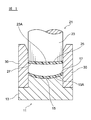
- FIG. 1 is a schematic view showing an example of a mold according to an embodiment of the present invention.
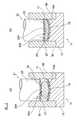
- FIG. 2 is an enlarged cross-sectional view of a lower mold that is a part of the mold shown in FIG.
- FIG. 3 is a schematic view showing an example of a pressing process using a mold according to an embodiment of the present invention.
- FIG. 4 is a flowchart showing a process of manufacturing an optical lens from a polishing glass lens blank.
- a molding die according to the present invention is a molding die that has at least an upper die and a lower die, and is used for producing a glass optical element blank for polishing by press-molding a softened glass material in an air atmosphere. At least one molding surface of the upper mold and the lower mold has an oxide ceramic film having a thickness of 5 ⁇ m or more.
- the molding die even in the case of producing a polishing glass optical element blank by press molding a softened glass material in an air atmosphere, the molding die (particularly the upper die and / or Alternatively, deterioration of the molding surface of the lower mold) can be prevented, continuous press molding can be performed, and productivity of the molding process can be improved.
- FIG. 1 is a schematic view showing an example of a molding die according to an embodiment of the present invention.
- the molding die illustrated in FIG. 1 includes an upper die 21 and a lower die 11 having molding surfaces, and an annular body die 30 that regulates these substantially coaxially, and each of the upper die 21 and the lower die 11.
- the molding surfaces 27 and 17 have oxide ceramic films 25 and 15 having a film thickness of 5 ⁇ m or more.
- the body die 30 is an arbitrary constituent member. That is, the body mold 30 is not necessarily required when the upper mold 21 and the lower mold 11 can be regulated to be substantially coaxial by another method.
- the oxide ceramic film may be formed on at least one of the lower mold 11 and the upper mold 21, and preferably formed on both.
- FIG. 2 is an enlarged cross-sectional view of the lower mold 11 which is a part of the mold shown in FIG.
- the upper mold 12 is not described here, but can be the same as that of the lower mold 11.
- the lower mold 11 that is a part of the mold according to the present embodiment includes a base material 13 and an oxide ceramic film 15 formed on the base material surface 13 ⁇ / b> A.
- the surface of the film 15 is a molding surface 17. That is, the molding surface 17 according to the present embodiment includes the oxide ceramic film 15 having a film thickness t of 5 ⁇ m or more.
- Such a lower mold 11 prevents the substrate surface 13A from coming into direct contact with atmospheric oxygen or softened glass even when reheat press molding is repeatedly performed in an air atmosphere. Further, in the molding surface 17 according to this embodiment, glass is hardly fused and remains on the molding surface, and physical deterioration of the molding surface can be prevented.
- the lower mold 11 according to this embodiment having such a molding surface 17 has high durability against continuous press molding.
- the film thickness t of the oxide ceramic film 15 according to this embodiment is 5 ⁇ m or more, preferably 10 ⁇ m or more, more preferably 20 ⁇ m or more.
- membrane 15 is 80 micrometers or less, More preferably, it is 50 micrometers or less. If the thickness t of the oxide ceramic film 15 becomes too thin, the durability of the molding surface 17 with respect to continuous press molding tends to decrease. Further, as the thickness t of the oxide ceramic film 15 becomes larger than necessary, the oxide ceramic film 15 is easily peeled off.
- the film thickness t of the oxide ceramic film according to the present invention refers to nine places (for example, any nine places on two lines orthogonal to each other through the center point of the molding surface) in the oxide ceramic film formed on the molding surface. (The center point of the molding surface and four points each of r / 3 and 2r / 3 when the radius of the molding surface is r)) The average film thickness is shown.
- the film thickness of the oxide ceramic film is measured, for example, by measuring the fracture surface of the film with an SEM, using a known ultrasonic film thickness meter, electromagnetic induction film thickness meter, ⁇ -ray transmission film thickness meter, or the like. be able to.
- the oxide ceramic film 15 according to the present embodiment is preferably formed so as to cover the entire surface of the substrate surface 13A evenly.
- the oxide ceramic film 15 is composed mainly of an oxide ceramic. Accordingly, the oxide ceramic film 15 preferably contains 60% by mass or more of oxide ceramic, more preferably 80% by mass or more, still more preferably 90% by mass or more, and particularly preferably 95% or more. Since the oxide ceramic film 15 is mainly composed of an oxide ceramic, even when used in a high-temperature oxidizing atmosphere, the coating film can be prevented from being deteriorated, and the molding surface is chemically and physically deteriorated. Can be prevented.
- examples of such an oxide ceramic include at least one selected from the group consisting of silica, alumina, zirconia, titania, magnesia, and calcia.
- silica is preferable from the viewpoint of the durability of the coating.
- the oxide ceramic film 15 may be composed of any one of the above oxide ceramics or a mixture thereof, but is preferably composed of silica alone.
- the oxide ceramic film 15 includes, as components other than the oxide ceramic, for example, boron nitride (BN), silicon carbide (SiC), aluminum nitride (AlN), iron oxide (Fe 2 O 3 ), chromium oxide ( Components such as Cr 2 O 3 ) and aluminum phosphate (AlPO 4 ) may be included. These components may be included intentionally or may be included unavoidably (to the extent of impurities). In addition, when the oxide ceramic film 15 contains these components, it is preferable that the sum total of the content is 40 mass% or less. When these components are too much, the oxide ceramic film 15 tends to be brittle, and the molding surface tends to deteriorate due to continuous press molding.
- the oxide ceramic film 15 may contain various oxide components, metal components, and the like that cannot be excluded in production in addition to the above components as inevitable components.
- the base material 13 has a surface 13A corresponding to the molding surface 17.
- the shape of such a surface 13A is formed so as to follow the shape of the glass molded body (glass optical element blank for polishing) to be molded.
- a convex curved surface shape, a concave curved surface shape, a planar shape, etc. are mentioned.
- the material of the base material 13 can be appropriately selected according to the hardness of the glass to be molded, the glass transition temperature Tg, and the like, and examples thereof include stainless steel and cast iron.
- Stainless steel is more expensive than cast iron, but is suitable for glass materials having a relatively high glass transition temperature because it has high heat resistance and can withstand long-term use.
- Cast iron is inexpensive and has good workability. Therefore, the material of the base material 13 can be appropriately selected according to the characteristics of the glass to be molded. Note that, from the viewpoint of improving the adhesion between the base material 13 and the oxide ceramic film 15, it is preferable to make the thermal expansion coefficients of both closer.
- molding die concerning this embodiment forms the oxide ceramic film
- a coating solution is prepared.
- the oxide ceramic film 15 is formed from a coating solution.
- the coating solution comprises at least an oxide ceramic and a solvent.
- oxide ceramic examples include at least one selected from the group consisting of silica, alumina, zirconia, titania, magnesia, and calcia.
- silica is preferable from the viewpoint of durability.
- the oxide ceramic may be used alone or in combination of two or more.
- oxide ceramic a powder having an average particle size of preferably 5 ⁇ m or less, more preferably 1 ⁇ m or less can be used.
- water or an organic solvent can be used as the solvent.
- the coating solution according to this embodiment is a mixture of at least an oxide ceramic and a solvent.
- the mixing method is not particularly limited, and a known method can be used. Further, the mixing ratio of the oxide ceramic and the solvent is not particularly limited, and can be appropriately adjusted so as to obtain a desired viscosity according to the coating method, as in a general paint.
- the coating solution may contain ceramics or oxides other than the above as solid components other than the oxide ceramics.
- the total content of these components is preferably 40% by mass or less of the entire solid components (including oxide ceramics).
- the coating solution may contain additives such as various dispersants, binders, and plasticizers as necessary.
- the total content of these additives is desirably 10% by mass or less of the entire coating solution.
- the coating solution according to the present embodiment preferably contains colloidal silica as a binder. Since colloidal silica forms an oxide ceramic film as silica after firing, a strong film can be formed.
- the base material 13 corresponding to the lower mold is prepared. What is necessary is just to select the material of the base material 13 suitably according to the material (characteristic) of the glass which performs press molding, press temperature, etc. FIG. Moreover, the shape of the base material 13 can be suitably selected according to the shape of a press apparatus and the target glass molded object (glass optical element blank for grinding
- the shape of the substrate surface 13A corresponds to the shape of the molding surface 17. That is, the shape of the surface 13A is formed so as to follow the shape of the glass molded body to be molded, and is appropriately set according to the target shape of the glass molded body. For example, it can be a convex curved surface, a concave curved surface, a flat surface, or the like.
- the base material surface 13A may be subjected to pretreatment such as blasting as necessary. Further, it is desirable that the base material surface 13A removes dust such as fats and oils and grinding scraps. By performing these treatments, the adhesion between the substrate surface 13A and the oxide ceramic film 15 can be enhanced.
- the application method is not particularly limited, and can be performed by a known method. Examples thereof include a spray coating method, a brush coating method, and a dipping method.
- the coating amount can be adjusted as appropriate according to the film thickness t of the oxide ceramic film 15 to be formed. However, when the film thickness t is increased, it is preferable to apply the coating in several times. If a large amount of coating solution is applied at once, cracks may occur in the oxide ceramic film after drying. Further, depending on the shape of the base material, the thickness of the oxide ceramic film after drying may vary.
- the molding surface 17 follows the shape of the substrate surface 13A.
- the oxide ceramic dispersed in the coating solution is likely to aggregate and precipitate in the recesses on the surface 13A.
- the thickness of the oxide ceramic film after drying becomes thicker at the center than at the outer periphery, and the curvature may differ between the molding surface 17 and the surface 13A.
- the coated surface is appropriately dried.
- the coated surface is coated after confirming that the coated surface is properly dried by touching the coated surface.
- the drying temperature can be from room temperature to 200 ° C.
- the drying time can be appropriately adjusted according to the type of solvent and the coating amount, but can be about 1 to 6 hours.
- the mold with the coated surface sufficiently dried is fired to cure the coating material [firing step].
- the firing conditions can be adjusted as appropriate according to the type and thickness of the oxide ceramic.
- the firing temperature can be 90 to 150 ° C.
- the firing time can be about 10 minutes to 1 hour. .
- the said baking process is an arbitrary process. That is, since it is necessary to control the mold at a predetermined temperature in a press process described later, the mold can be fired (curing of the coating material) in the firing process by heating at that time.
- the molding surface 17 having the oxide ceramic film 15 having a film thickness t of 5 ⁇ m or more can be formed on the lower mold 11 which is a part of the molding die according to this embodiment.
- the oxide ceramic film 15 is in close contact with the substrate surface 13A, and is not peeled off from the substrate 13 even when heated and pressurized in the atmosphere.
- the molding surface 17 according to the present embodiment has moderate unevenness. That is, the coating material is cured on the substrate surface 13A to form the oxide ceramic film 15. At this time, it is preferable that the surface roughness Rz of the molding surface 17 exceeds 10 ⁇ m. Such a molding surface 17 is expected to have an effect of keeping the softened glass material before pressing and a rapid cooling effect of the glass material after pressing.
- the method for producing a polishing glass optical element blank according to this embodiment is as follows. Preparing a mold according to the present embodiment; And a pressing step of press-molding the softened glass material with the mold after reheating the glass material made of optical glass in an air atmosphere.
- a mold shown in FIG. 1 is prepared as a mold. That is, a lower die 11 having an oxide ceramic film 15 having a thickness of 5 ⁇ m or more on the molding surface 17, an upper die 21 having an oxide ceramic film 25 having a thickness of 5 ⁇ m or more on the molding surface 27, and a body die 31 are prepared. To do. Further, the mold is heated in advance. The heating temperature of the mold is preferably adjusted as appropriate depending on the glass material to be molded, but the temperature of the mold should be heated so that it is close to the yield point (Ts) of the glass material to be molded. Is desirable.
- Ts yield point
- a required quantity of glass material 40a processed into a predetermined shape for example, polyhedron shape, disk shape, spheroid shape, etc.
- a predetermined weight weight more than the target optical element
- the material of the glass material 40a is not particularly limited.
- the method for forming the glass material 40a is not particularly limited.
- a substantially hexahedral glass piece obtained by cutting a plate-shaped glass plate, a disk-shaped glass piece obtained by cutting a cylindrical glass material at equal intervals, or a melt flowing down from a nozzle examples thereof include glass pieces obtained by receiving glass with a receiving mold, forming it into a spheroid shape, and cooling it.
- the glass material 40 a that has been softened by heating in advance is supplied to the lower mold 11. Thereafter, the upper mold 21 is inserted into the trunk mold 30. In FIG. 2 (A), since the load by the upper mold
- a release agent is applied to at least one of the glass material 40a and the molding surfaces 17 and 27 in order to prevent glass fusion.
- a powder release agent such as boron nitride, alumina, silicon oxide, magnesium oxide is used.
- molding die concerning this embodiment has the oxide ceramic films
- the upper mold 21 is lowered to press the glass material 40a, and the glass material 40a is press-molded into a shape that follows the molding surface shape of the upper and lower molds.
- An element blank 40b is obtained.
- the glass material 40a at the time of press molding is preferably kept at a viscosity of 10 4 to 10 6 dPa ⁇ s. Moreover, press molding is performed in air
- the shape of the polishing glass optical element blank 40b is a biconvex shape, a shape having a convex surface and a plane, a shape having a concave surface and a plane, both There is no particular limitation as long as the shape approximates the shape of the target glass optical element, such as a concave shape.
- the molded glass optical element blank 40b for polishing is taken out from the mold and subjected to heat treatment (annealing treatment) for removing strain as necessary.
- the molding surfaces 17 and 27 of the upper mold 21 and the lower mold 11 have the oxide ceramic films 15 and 25, the molded glass optical element blank 40b for polishing is formed.
- the glass can be easily taken out, and the glass remains hardly caused by fusion on the molding surfaces 17 and 27 after the polishing glass optical element blank 40b is removed, and the physical degradation of the molding surface is extremely small.
- the mold particularly the lower mold 11 and the upper mold 21
- the number of shots is 500 times or more, more preferably 700 times or more
- the above pressing process is continuously repeated a plurality of times. Can do.
- one of the major factors that hinders the continuous use of molds is the fusion of glass to the molding surface.
- a release agent to at least one of the molding surface and the glass material.
- the release agent does not sufficiently cover the molding surface and the glass material, or when the glass softened by pressing during press molding is a gap between the release agents Since a part where the molding surface and the glass are in direct contact with each other, such as when exuding from the glass, glass fusion can occur.
- the molding surface was the surface of the mold base (the part corresponding to 13A and 23A in FIG. 2). For this reason, when the glass is fused to the molding surface, the fused glass is in direct contact with the substrate surface. When glass is directly fused to the substrate surface, the fused glass tends to remain on the molding surface (substrate surface) even if the molded body (glass optical element blank for polishing 40b) is removed. Since it is difficult to continue using the mold in which the glass fused on the molding surface remains, it is necessary to maintain the molding surface or replace the molding die itself.
- the molding surfaces 17 and 27 of the lower die 11 and the upper die 21 have the oxide ceramic films 15 and 25. Even when pressed against the oxide ceramic films 15 and 25, the glass is easily released from the molding surfaces 17 and 27. This is because the oxide ceramic films 15 and 25 have moderate brittleness, and when the molded body (polishing glass optical element blank 40b) is taken out, the oxide ceramic films 15 and 25 are worn and have a releasing action. Because it brings. Therefore, the molding surfaces 17 and 27 after releasing the molded body 40b are not easily fused, and the molding die can be used continuously.
- the thickness of the oxide ceramic film formed on the molding surface tends to be gradually reduced. Therefore, when the thickness of the oxide ceramic film is too thin, the oxide ceramic film may be removed from the molding surface, and the substrate surface may be exposed. Since the glass may be fused at such a portion where the surface of the base material is exposed, there is a problem that the fused glass remains on the molding surface even after the molded body is removed. That is, the oxide ceramic film needs to have an appropriate thickness from the viewpoint of enabling continuous press molding and sufficiently protecting the surface of the base material.
- the molding die according to this embodiment at least one molding surface of the upper die and the lower die has an oxide ceramic film having a thickness of 5 ⁇ m or more. According to such a mold, even if reheat press molding is continuously repeated, exposure of the substrate surface can be prevented and the substrate surface can be sufficiently protected. Furthermore, from the viewpoint of sufficiently protecting the substrate surface and improving the number of continuous uses of the mold, the oxide ceramic film is preferably as thick as possible, preferably 10 ⁇ m or more, more preferably 20 ⁇ m or more.
- a preferable upper limit of the thickness of the oxide ceramic film is 80 ⁇ m or less, and more preferably 50 ⁇ m or less.
- the molding surface of at least one of the upper die and the lower die has the oxide ceramic film having a film thickness of 5 ⁇ m or more, the upper die and the lower die are formed.
- the corresponding base material surface can be prevented from coming into direct contact with atmospheric oxygen or softened glass, and deterioration of the base material surface corresponding to the molding surface can be prevented.
- the lifetime of the substrate can be improved.
- the mold according to the present embodiment it is easy to reuse the base material corresponding to the upper mold and the lower mold. That is, in the mold according to this embodiment, even if the glass fused to the molding surface remains, the substrate surface corresponding to the molding surface is protected by the oxide ceramic film, Not affected. Therefore, even if maintenance of the molding surface is required, the fused glass may be removed together with the oxide ceramic film, and the original substrate surface can be easily recovered. Furthermore, if an oxide ceramic film is formed again on such a substrate, it can be reused as the mold according to this embodiment.
- the effect of improving the yield rate in the molded body can be expected without strictly controlling the temperature of the mold.
- a glass material is heated and softened, and the softened glass is press-molded to form a polishing glass optical element blank that approximates the shape of the target optical element.
- the glass to be molded is maintained at an appropriate viscosity (preferably 10 4 to 10 6 dPa ⁇ s) at the time of pressing.
- the softened glass when put into the mold, if the temperature of the mold is low, the temperature of the glass material rapidly decreases, and the viscosity increases during press molding (that is, the glass becomes hard). When such a glass material is pressed, a molding defect (can crack / nozzle defect) may occur in the molded body (glass optical element blank for polishing). For this reason, it is desirable that the mold is sufficiently heated.
- the temperature control of the mold is important in improving the yield rate of the molded product. Therefore, with conventional molds, it is necessary to strictly control the mold within an appropriate temperature range (temperature at which molding defects can be prevented and glass fusion can be suppressed) in order to improve the yield rate and production efficiency. there were.
- the mold according to this embodiment can improve the yield rate of the molded body without strictly controlling the temperature of the mold.
- the present inventors speculate as follows.
- the molding surfaces 17 and 27 have oxide ceramic films 15 and 25. Therefore, the glass material 40 a put into the lower mold 11 does not directly contact the base material surface 13 ⁇ / b> A of the lower mold 11, but comes into contact with the surface 17 of the oxide ceramic film 15. In this case, compared with the case where the glass material 40a is in direct contact with the base material surface 13A of the lower mold 11, the temperature of the glass material 40a is not rapidly decreased, and the heat transfer is considered to be gentle. As a result, even if the temperature of the lower mold 11 is lower than an appropriate temperature range, it is considered that the glass material 40a is kept warm and can maintain an appropriate viscosity until pressing. In addition, it is considered that rapid thermal shock due to a temperature difference between the glass material and the mold can be suppressed.
- the molding surface after the molded body 40b is released. 17 and 27 are less likely to retain fused glass.
- the polishing glass optical element blank produced by the mold according to this embodiment is less prone to molding and has excellent shape accuracy. Therefore, in the subsequent grinding and polishing steps, the processing amount and processing time can be reduced, and the productivity is excellent.
- the manufacturing method of the optical element according to this embodiment is as follows: Grinding the polishing glass optical element blank produced by the method for manufacturing a polishing glass optical element blank according to the present embodiment; Polishing the polishing optical element blank that has undergone the grinding step.
- optical element obtained by such a method examples include spherical lenses, aspherical lenses, macro lenses, various lenses such as a lens array, prisms, diffraction gratings, and the like.
- the grinding step is a process of grinding both surfaces of the glass optical element blank 40b to a predetermined radius of curvature using a grinding wheel such as a diamond wheel.
- the polishing step is a process of polishing both surfaces of the ground optical element blank using a polishing dish and using free abrasive grains such as cerium oxide as an abrasive.
- a spherical grinding step (CG processing) of the main surface of the lens blank 40b is first performed.
- the curve generator used for CG processing is not particularly limited, and a known one such as a diamond grindstone is used.
- the surface of the lens blank is roughly ground with a machining allowance of several tens of ⁇ m to several hundreds of ⁇ m, and both surfaces are ground so as to approximate the curvature of the final lens shape.
- grinding is performed using a grindstone having a grain size of 20 to 60 ⁇ m (# 800 to # 400 in grain size display) while supplying a grinding fluid.
- the numerical value of a particle size display becomes large, so that the particle size of an abrasive grain is small.
- a smoothing process (SM process) by a fine grinding process is performed.
- the SM processing may be one-step processing, but may be multi-step processing.
- a grindstone used for SM processing a metal bond grindstone and a resin bond grindstone can be used in combination, or only a resin bond grindstone can be used.
- the resin bond grindstone is preferably a grindstone having a grain size of 8 to 20 ⁇ m (# 2500 to # 1200 in terms of grain size).
- step S12 polishing is performed.
- the surface is polished with a polishing liquid containing polishing abrasive grains having a particle diameter of 5 ⁇ m or less (for example, cerium oxide free abrasive grains) to polish several ⁇ m to several tens of ⁇ m.
- a polishing liquid containing polishing abrasive grains having a particle diameter of 5 ⁇ m or less for example, cerium oxide free abrasive grains
- the centering process may be omitted depending on circumstances.
- the optical lens body is sandwiched between a pair of lens holders and centered, and while rotating the lens body around its center line, the side peripheral surface of the lens body is ground to a perfect circle with a diamond grindstone or the like. It is processing to do.
- various optical lenses such as a biconvex lens, a biconcave lens, a planoconvex lens, a planoconcave lens, a convex meniscus lens, and a concave meniscus lens can be obtained.
- optical functional surface of the obtained lens may be coated with an antireflection film, a total reflection film or the like according to the purpose of use.
- the polishing glass optical element blank according to the present embodiment is used, so that the processing amount and processing time in the grinding step and the polishing step can be significantly reduced. , Improve productivity.
- the oxide ceramic film is formed only on the molding surfaces of the lower die and the upper die is shown.
- the oxide is also applied to the barrel die.
- a ceramic film may be formed.
- the mold used for producing the glass lens blank for polishing has been described as an example, but the present invention is not limited to such a mold. That is, the shaping
- Mold preparation ⁇ Mold I> First, water as a solvent was added to a coating material containing silica as a main component and colloidal silica as a binder, and stirred sufficiently to obtain a coating solution having a desired viscosity.
- an upper mold, a lower mold, and a body mold made of stainless steel were prepared as base materials for the mold.
- the airbrush was filled with a coating solution that had been adjusted to an appropriate viscosity in advance, and the coating solution was misted and spray-coated uniformly over the entire surface corresponding to the molding surface of the upper and lower mold surfaces.
- the mold I thus obtained had an oxide ceramic film of about 20 ⁇ m on the molding surface.
- the film thickness of the oxide ceramic film was measured using a Fischer film thickness meter DUALSCOPE. The same applies hereinafter.
- Mold II was produced in the same manner as Mold I except that the oxide ceramic film thickness was 5 ⁇ m.
- Mold III was produced by the same method as Mold I except that the main component of the coating material was alumina and the thickness of the oxide ceramic film was 30 ⁇ m.
- Mold IV was produced by the same method as Mold I except that the main component of the coating material was zirconia and the oxide ceramic film thickness was 50 ⁇ m.
- the mold V was produced by the same method as the mold I except that the thickness of the oxide ceramic film was 80 ⁇ m.
- the forming die VI was produced in the same manner as the forming die I except that silicon nitride was formed using a sputtering apparatus instead of the oxide ceramic film and the film thickness was changed to 30 ⁇ m.
- Mold VII was produced in the same manner as Mold I except that the oxide ceramic film was not formed and the surface of the substrate was used as the molding surface.
- lens blank was prepared using the above molds I to VII. Whichever mold was used, the following lens blanks A and B were prepared.
- the glass material coated with the release agent was supplied to a tray, put into a heating furnace set at 450 to 700 ° C., and reheated in an air atmosphere.
- the reheated optical glass material for press molding softened to a viscosity of about 10 5 dPa ⁇ s.
- the glass blank softened by reheating was press-molded in an air atmosphere using a molding die to produce a lens blank A having a single-sided convex shape, a diameter of 40 mm, and a height of 5 mm.
- a mold release agent was applied in advance to the molding surface of the mold, and the mold was preheated to a temperature in the vicinity of the yield point (Ts).
- a powder release agent boron nitride
- the glass material coated with the release agent was supplied to a receiving tray, put into a heating furnace set at 700 to 900 ° C., and reheated in an air atmosphere.
- the reheated optical glass material for press molding softened to a viscosity of about 10 5 dPa ⁇ s.
- the glass blank softened by reheating was press-molded in an air atmosphere using a molding die to produce a lens blank B having a single-sided convex shape, a diameter of 30 mm, and a height of 4 mm.
- a mold release agent was applied in advance to the molding surface of the mold, and the mold was preheated to a temperature in the vicinity of the yield point (Ts).
- the molding die VI in which the ceramic film is formed using silicon nitride which is a material other than the oxide ceramic has improved durability as compared with the molding die VII.
- silicon nitride is oxidized and the ceramic film on the molding surface becomes brittle (film deteriorates) during repeated press molding. It was. As a result, the molding surface peeled off before the number of shots was less than 200, and the substrate surface of the molding die was exposed. Thereafter, the glass remained fused on the exposed substrate surface, and the mold could not be used continuously.
- the molding surface has an oxide ceramic having a film thickness of 5 ⁇ m or more, so that the surface of the base material of the molding dies can be sufficiently protected and further fused. It was also possible to prevent the glass from remaining on the molding surface, and it was confirmed that continuous molding of 500 times or more is possible regardless of the composition of the glass material to be molded and the shape of the molded body.
- the fused glass remains on the molding surface (base material surface) only by repeating the press molding a dozen times, and the molding die is It was necessary to replace the mold, and it was necessary to replace the mold six times until 100 lens blanks were produced. Furthermore, in the lens blank produced with the mold VII, nodding defects and cracks occurred frequently, resulting in 22% defective products.
- the number of replacements of the mold was one.
- This one-time mold change occurred when about 1000 lens blanks were produced, and was not caused by the fact that the fused glass remained on the molding surface, and other parts of the molding mold deteriorated. Was the cause.
- a lens blank was produced by the same method as the lens blanks A and B described above, except that was adjusted.
- the wider temperature range for press molding eliminates the need for precise temperature control of the mold, improving productivity, and even press molding in a relatively low temperature region. Since molding defects do not occur, it has been found that the shape variation after molding is reduced and the quality is stabilized.
Landscapes
- Engineering & Computer Science (AREA)
- Chemical & Material Sciences (AREA)
- Manufacturing & Machinery (AREA)
- Materials Engineering (AREA)
- Organic Chemistry (AREA)
- Re-Forming, After-Treatment, Cutting And Transporting Of Glass Products (AREA)
- Moulds For Moulding Plastics Or The Like (AREA)
- Surface Treatment Of Glass (AREA)
Abstract
【課題】 本発明は、大気雰囲気において、軟化したガラス素材をプレス成形して研磨用ガラス光学素子ブランクを製造するために用いる成形型であって、耐久性に優れた長寿命の成形型を提供することを目的とする。 【解決手段】 本発明に係る成形型は、少なくとも上型および下型を有し、大気雰囲気において、軟化したガラス素材をプレス成形して研磨用ガラス光学素子ブランクを製造するために用いる成形型であって、前記上型および下型の少なくとも一方の成形面は、膜厚が5μm以上の酸化物セラミック膜を有する。
Description
本発明は、研磨用ガラス光学素子ブランク用成形型、並びに、研磨用ガラス光学素子ブランクおよび光学素子の製造方法に関する。
近年、光学素子の多様化および広範化に伴い、ガラス製の光学素子の需要が高まってきている。
光学レンズ等のガラス光学素子の成形方法としては、軟化させたガラスをプレスして成形する、プレス成形法が知られている。このようなプレス成形法を大別すると、ダイレクトプレス成形法、リヒートプレス成形法、および精密プレス成形法(モールドプレス成形法とも呼ばれる)の3つの方法が挙げられる。
これらの成形方法のうちダイレクトプレス成形法とリヒートプレス成形法は、軟化したガラス素材を短時間でプレス成形して、目的とする光学素子形状に近似した光学素子ブランクを形成し、その後、その光学素子ブランクを研削・研磨して光学素子に仕上げる方法である。一方、精密プレス成形法は、精密加工された成形面形状を、非酸化雰囲気中で軟化したガラスに転写することで、目的とする光学素子を形成する方法であり、この方法では成形品の研削・研磨は不要である。
特に、リヒートプレス成形法は、プレス成形を大気雰囲気中で行うことができ、比較的高価な設備を必要としないことから、従来から広く用いられている(特許文献1)。しかし、この方法では、以下のような問題がある。
通常、リヒートプレス成形は、鋳鉄などの金属材料で構成される成形型を用いて、大気雰囲気下で行われる。その際、成形型の成形面は、高温で、大気や軟化したガラス素材と直接接触することになる。そのため、大気中の酸素やガラス素材を構成するガラス成分と、成形面を構成する材料(鋳鉄などの金属材料)とが反応して、成形面が化学的に劣化し易くなる。
また、リヒートプレス成形では、軟化したガラス素材を成形型で押圧することにより、所定の形状を有した成形体(研磨用ガラス光学素子ブランク)を形成する。その際、軟化したガラスが成形面に融着することがある。特に、リヒートプレス成形を繰り返していくと、成形面の化学的な劣化が進むため、成形面へのガラスの融着が助長される傾向にある。
このような成形面へのガラスの融着は、離型性の悪化や、成形面の物理的な劣化を招く。すなわち、成形面へのガラスの融着が起こると、プレス成形後の成形体を成形型から分離できなくなる、あるいは、成形体を離型できても、離型後の成形面に融着したガラスが残存して成形面の凹凸の原因となることがある。このような場合には、同じ成形型を継続的に使用できないため、連続的なプレス工程を中断して、頻繁に成形面のメンテナンスや成形型の交換を行う必要がある。
このように、リヒートプレス成形では、成形型(特に成形面)の寿命が短くなることが問題であった。しかし、近年の光学素子の需要の高まりに伴い、光学素子の生産性の向上や低コスト化が望まれてきており、これらを達成する上で、成形型の長寿命化は必須の課題であった。特に、成形面の耐久性の向上が望まれていた。
例えば、成形面の耐久性を向上させる方法としては、従来から知られている鋳鉄などの金属面の保護方法(例えばCrメッキや金属皮膜の形成等)により、成形面を保護する技術が挙げられる。しかし、このような成形面の保護方法は、常温で使用する成形型に対しては好適であるが、高温の大気雰囲気下で使用するリヒートプレス用の成形型に対しては、Crメッキなどの被膜が劣化し易く、連続的な複数回のプレス成形では十分に成形面を保護できていかなった。
また、成形面へのガラスの融着を防止する方法としては、プレス成形時に、成形型およびガラス素材の少なくともいずれか一方に、窒化ホウ素等の離型剤を塗布する技術が従来から用いられている。しかし、このような方法では、離型性は向上するものの、窒化ホウ素等の離型剤は比較的流動的である(成形面に固定化されていない)ため、成形面の一部が露出することがあり、成形面へのガラスの融着を十分に防止できていなかった。
本発明は、このような実状に鑑みてなされ、その目的は、大気雰囲気において、軟化したガラス素材をプレス成形して研磨用ガラス光学素子ブランクを製造するために用いる成形型であって、耐久性に優れた長寿命の成形型を提供することである。
本発明者らは、上記課題を解決するために鋭意試験研究を重ねた結果、成形型の成形面に対応する基材表面を、所定の厚みを有する酸化物セラミック膜で保護することにより、大気雰囲気下でのリヒートプレス成形に対しても、成形型(特に成形面)の耐久性を向上できることを見出し、本発明を完成するに至った。
本発明の要旨は以下の通りである。
[1] 少なくとも上型および下型を有し、
大気雰囲気において、軟化したガラス素材をプレス成形して研磨用ガラス光学素子ブランクを製造するために用いる成形型であって、
上記上型および下型の少なくとも一方の成形面は、膜厚が5μm以上の酸化物セラミック膜を有する、成形型。
[1] 少なくとも上型および下型を有し、
大気雰囲気において、軟化したガラス素材をプレス成形して研磨用ガラス光学素子ブランクを製造するために用いる成形型であって、
上記上型および下型の少なくとも一方の成形面は、膜厚が5μm以上の酸化物セラミック膜を有する、成形型。
[2] 上記酸化物セラミック膜は、シリカ、アルミナ、ジルコニア、チタニア、マグネシア、およびカルシアからなる群から選択される少なくとも1種を含む、上記[1]に記載の成形型。
[3] 上記酸化物セラミック膜は、コロイダルシリカを含む、上記[1]または[2]に記載の成形型。
[4] 上記酸化物セラミック膜は、50μm以下である、上記[1]~[3]のいずれかに記載の成形型。
[5] 上記[1]~[4]のいずれかに記載の成形型を用意する工程と、
光学ガラスからなるガラス素材を大気雰囲気下で再加熱した後、軟化した上記ガラス素材を上記成形型でプレス成形するプレス工程と
を含む研磨用ガラス光学素子ブランクの製造方法。
光学ガラスからなるガラス素材を大気雰囲気下で再加熱した後、軟化した上記ガラス素材を上記成形型でプレス成形するプレス工程と
を含む研磨用ガラス光学素子ブランクの製造方法。
[6] 上記[5]に記載の製造方法によって製造された研磨用ガラス光学素子ブランクを研削する工程と、
上記研削工程を経た研磨用ガラス光学素子ブランクを研磨する工程と
を含む光学素子の製造方法。
上記研削工程を経た研磨用ガラス光学素子ブランクを研磨する工程と
を含む光学素子の製造方法。
本発明の成形型によれば、大気雰囲気下で、軟化したガラス素材をプレス成形し、研磨用ガラス光学素子ブランクを製造する場合であっても、成形型(特に成形面)の劣化を防止でき、連続的なプレス成形が可能となり、成形工程の生産性を向上できる。
本発明に係る成形型は、少なくとも上型および下型を有し、大気雰囲気において、軟化したガラス素材をプレス成形して研磨用ガラス光学素子ブランクを製造するために用いる成形型であって、上記上型および下型の少なくとも一方の成形面は、膜厚が5μm以上の酸化物セラミック膜を有する。
このような本発明の成形型によれば、大気雰囲気下で、軟化したガラス素材をプレス成形し、研磨用ガラス光学素子ブランクを製造する場合であっても、成形型(特に、上型および/または下型の成形面)の劣化を防止でき、連続的なプレス成形が可能となり、成形工程の生産性を向上できる。
以下、本発明の成形型およびその製造方法、並びに、本発明の成形型を用いたプレス工程(研磨用ガラス光学素子ブランクの製造方法)について詳細に説明するが、本発明は、以下の実施形態に何ら限定されるものではなく、本発明の目的の範囲内において、適宜変更を加えて実施できる。なお、説明が重複する箇所については、適宜説明を省略する場合があるが、発明の趣旨を限定するものではない。
<成形型>
以下、図1に示す成形型を例に、本発明の一形態について説明する。なお、図中同一または相当部分には同一の符号を付してその説明は繰り返さない。
以下、図1に示す成形型を例に、本発明の一形態について説明する。なお、図中同一または相当部分には同一の符号を付してその説明は繰り返さない。
図1は、本発明の一実施形態に係る成形型の一例を示す概略図である。図1に例示される成形型は、成形面を有する上型21および下型11と、これらを略同軸状に規制する環状の胴型30とで構成され、上型21および下型11のそれぞれの成形面27、17は、膜厚が5μm以上の酸化物セラミック膜25、15を有する。
なお、本実施形態に係る成形型において、胴型30は任意の構成部材である。すなわち、胴型30については、他の方法で上型21および下型11を略同軸状に規制できる場合には、必ずしも必要ではない。
また、本実施形態に係る成形型において、酸化物セラミック膜は、下型11および上型21の少なくともいずれか一方に形成されていればよく、好ましくは、両方に形成されているのが望ましい。
次に、図2に示す下型を例に、本実施形態に係る成形型について詳しく説明する。図2は、図1に示す成形型の一部である下型11を拡大した断面図である。なお、上型12については、説明を省略するが、下型11の場合と同様とすることができる。
図2に示すように、本実施形態に係る成形型の一部である下型11は、基材13と、基材表面13Aに形成された酸化物セラミック膜15とで構成され、酸化物セラミック膜15の表面を成形面17とする。すなわち、本実施形態に係る成形面17は、膜厚tが5μm以上の酸化物セラミック膜15を有する。
このような下型11によれば、大気雰囲気下でリヒートプレス成形を繰り返し行っても、基材表面13Aが、大気中の酸素や軟化したガラスと直接接触することが防止される。また、このような本実施形態に係る成形面17では、ガラスが融着して成形面に残存することが少なく、成形面の物理的な劣化を防止できる。このような成形面17を有する本実施形態に係る下型11は、連続的なプレス成形に対して高い耐久性を有する。
本実施形態に係る酸化物セラミック膜15の膜厚tは5μm以上であり、好ましくは10μm以上、より好ましくは20μm以上である。また、酸化物セラミック膜15の膜厚tの好ましい上限は80μm以下、より好ましくは50μm以下である。酸化物セラミック膜15の膜厚tが薄くなりすぎると、連続的なプレス成形に対する成形面17の耐久性が低下する傾向にある。また、酸化物セラミック膜15の膜厚tが、必要以上に厚くなるにつれて、剥離し易くなる。
なお、本発明に係る酸化物セラミック膜の膜厚tとは、成形面に形成された酸化物セラミック膜における9ヶ所(例えば、成形面の中心点を通って直交する2線上の任意の9カ所(成形面の中心点と、成形面の半径をrとした時のr/3および2r/3の各4点))以上の平均膜厚を示す。酸化物セラミック膜の膜厚は、例えば、膜の破断面のSEMによる測定や公知の超音波式膜厚測定器、電磁誘導式膜厚計、β線透過式膜厚計などを用いて測定することができる。
また、本実施形態に係る酸化物セラミック膜15は、好ましくは、基材表面13Aの全面に、万遍なく覆う様に、形成されていることが望ましい。
本実施形態において、酸化物セラミック膜15は、酸化物セラミックを主成分として構成される。したがって、酸化物セラミック膜15は、好ましくは酸化物セラミックを60質量%以上、より好ましくは80質量%以上、さらに好ましくは90質量%以上、特に好ましくは95%以上含む。酸化物セラミック膜15は、酸化物セラミックを主成分とすることで、高温の酸化性雰囲気で用いた場合であっても、被膜の劣化を防止でき、ひいては成形面が化学的および物理的に劣化するのを防止できる。
また、このような酸化物セラミックとしては、例えば、シリカ、アルミナ、ジルコニア、チタニア、マグネシア、およびカルシアからなる群から選択される少なくとも1種が挙げられる。特に、被膜の耐久性の観点でシリカが好ましい。なお、酸化物セラミック膜15は、上記酸化物セラミックの単体または混合物のいずれで構成されていてもよいが、好ましくはシリカの単体で構成されるのが望ましい。
また、酸化物セラミック膜15は、上記酸化物セラミック以外の成分として、例えば、窒化ホウ素(BN)、炭化珪素(SiC)、窒化アルミ(AlN)、酸化鉄(Fe2O3)、酸化クロム(Cr2O3)、リン酸アルミニウム(AlPO4)等の成分を含んでいてもよい。これらの成分は意図的に含有させてもよいし、不可避的(不純物程度に)に含まれてもよい。なお、酸化物セラミック膜15がこれらの成分を含む場合には、その含有量の合計が、40質量%以下であることが好ましい。これらの成分が多すぎると、酸化物セラミック膜15が脆くなる傾向にあり、連続的なプレス成形により成形面が劣化する傾向にある。
また、酸化物セラミック膜15は、上記成分の他に、製造上排除できない各種酸化物成分や金属成分等を不可避成分として含んでいてもよい。
本実施形態において、基材13は、成形面17に対応する表面13Aを有する。このような表面13Aの形状は、成形するガラス成形体(研磨用ガラス光学素子ブランク)の形状に沿うように形成されている。例えば、凸曲面状、凹曲面状、平面状等が挙げられる。
また、基材13の材質は、成形するガラスの硬さやガラス転移温度Tg等に応じて適宜選択でき、例えば、ステンレス、鋳鉄等が挙げられる。ステンレスは鋳鉄に比べて高価であるが、耐熱性が高く長期間の使用に耐えるため、ガラス転移温度が比較的高い硝材に好適である。また、鋳鉄は安価で加工性が良い。したがって、基材13の材質は、成形するガラスの特性に応じて適宜選択できる。なお、基材13と酸化物セラミック膜15の密着性を高める観点から、両者の熱膨張係数を近づけることが好ましい。
<成形型の製造方法>
次に、図1に示す成形型の製造方法について一例を説明する。
本実施形態に係る成形型の製造方法は、上型および下型に対応する基材を準備する工程と、前記上型および下型の少なくとも一方の基材表面に、酸化物セラミック膜を形成する工程を有する。
次に、図1に示す成形型の製造方法について一例を説明する。
本実施形態に係る成形型の製造方法は、上型および下型に対応する基材を準備する工程と、前記上型および下型の少なくとも一方の基材表面に、酸化物セラミック膜を形成する工程を有する。
以下、図2の下型11の基材表面13Aに、酸化物セラミック膜15を形成する方法を説明する。なお、上型21については説明を省略するが、下型11の場合と同様とすることができる。
本実施形態では、まず、コーティング溶液を準備する。本実施形態では、コーティング溶液から酸化物セラミック膜15を形成する。コーティング溶液は、少なくとも酸化物セラミックと溶媒とを含んでなる。
酸化物セラミックとしては、例えば、シリカ、アルミナ、ジルコニア、チタニア、マグネシア、およびカルシアからなる群から選択される少なくとも1種が挙げられる。特に、耐久性の観点でシリカが好ましい。なお、酸化物セラミックは、1種類のみで用いてもよいし、2種類以上組み合わせて用いてもよい。
また、酸化物セラミックとしては、好ましくは平均粒子径が5μm以下、より好ましくは1μm以下の粉末を用いることができる。
また、溶媒としては、水や有機溶媒を用いることができる。
本実施形態に係るコーティング溶液は、少なくとも酸化物セラミックと溶媒とを混合してなる。混合方法は、特に限定されず、公知の方法を用いることができる。また、酸化物セラミックと溶媒との混合比率も、特に限定されず、一般的な塗料と同様に、塗布方法に応じた所望の粘度になるように、適宜調節できる。
また、コーティング溶液には、上記酸化物セラミック以外の固形成分として、上記以外のセラミックや酸化物等が含有されてもよい。ただし、これらの成分の総含有量は、固形成分全体(酸化物セラミックを含む)の40質量%以下とすることが好ましい。
さらに、コーティング溶液には、必要に応じて各種分散剤、結合材、可塑剤などの添加物が含有されてもよい。これら添加物の総含有量は、コーティング溶液全体の10質量%以下とすることが望ましい。
また、本実施形態に係るコーティング溶液は、好ましくは結合剤としてコロイダルシリカを含有することが好ましい。コロイダルシリカは、焼成後にシリカとして酸化物セラミック膜を構成するため、強固な膜を形成することができる。
次に、下型に対応する基材13を準備する。基材13の材質は、プレス成形を行うガラスの材質(特性)やプレス温度等に応じて適宜選択すればよい。また、基材13の形状は、プレス装置や目的とするガラス成形体(研磨用ガラス光学素子ブランク)の形状に応じて適宜選択できる。
特に、基材表面13Aの形状は、成形面17の形状に対応する。すなわち、表面13Aの形状は、成形するガラス成形体の形状に沿うように形成されており、ガラス成形体が目的とする形状に応じて適宜設定される。例えば、凸曲面状、凹曲面状、平面状等にすることができる。
なお、基材表面13Aについては、必要に応じてブラスト加工等の前処理を施してもよい。また、基材表面13Aは、油脂や研削屑等のごみを除去しておくことが望ましい。これらの処理を施すことにより、基材表面13Aと酸化物セラミック膜15の密着性を高めることができる。
次に、基材表面13Aに、コーティング溶液を塗布する〔塗布工程〕。塗布方法は、特に限定されず、公知の方法により行うことができる。例えば、スプレーコート法、刷毛塗り法、浸漬法等の方法が挙げられる。
塗布量については、形成しようとする酸化物セラミック膜15の膜厚t等に応じて、適宜調整できるが、膜厚tを厚くする場合には、数回に分けて重ね塗りするのが好ましい。一度に多量のコーティング溶液を塗布すると、乾燥後の酸化物セラミック膜にひび割れが生じることがある。また、基材の形状によっては、乾燥後の酸化物セラミック膜の膜厚にばらつきが生じることがある。
例えば、図2に示すように、成形面17は、基材表面13Aの形状に追従していることが望ましい。しかし、基材13のように、表面13Aが凹面である場合、表面13Aにコーティング溶液を多量に塗布すると、コーティング溶液中に分散した酸化物セラミックが表面13A上の凹部に凝集して沈殿し易くなる。その結果、乾燥後の酸化物セラミック膜の膜厚が、外周に比べて中心部分で厚くなり、成形面17と表面13Aとで曲率に違いを生じることがある。このような成形面17でプレス成形を行うと、成形体において形状不良を生じることがある。
なお、重ね塗りする場合には、塗布面が適度に乾燥されていることが望ましく、例えば塗布面を指触して適度に乾燥していることを確認した後に、塗り重ねるのが好ましい。
次に、コーティング溶液が塗布された成形型を、乾燥する〔乾燥工程〕。乾燥温度は、常温~200℃とすることができる。また、乾燥時間は、溶媒の種類や塗布量に応じて適宜調節できるが、1時間~6時間程度とすることができる。
その後、塗布面を十分に乾燥させた成形型を、焼成して、コーティング材料を硬化する〔焼成工程〕。焼成条件は、酸化物セラミックの種類や膜厚等に応じて適宜調節できるが、例えば、焼成温度は90~150℃とすることができ、焼成時間は10分~1時間程度とすることができる。
なお、上記焼成工程は任意の工程である。すなわち、後述するプレス工程で成形型を所定の温度に制御する必要があるため、その際の加熱により、上記焼成工程における成形型の焼成(コーティング材料の硬化)を兼ねることもできる。
このような方法により、本実施形態に係る成形型の一部である下型11について、膜厚tが5μm以上の酸化物セラミック膜15を有する成形面17を形成することができる。ここで、酸化物セラミック膜15は、基材表面13A上に密着しており、大気中で加熱され、加圧されても基材13から剥離することはない。
また、このような本実施形態に係る成形面17は、適度な凹凸を有することが好ましい。すなわち、コーティング材料が基材表面13A上で硬化することにより、酸化物セラミック膜15となるが、この時、成形面17の表面粗さRzが10μmを超えることが好ましい。このような成形面17には、押圧前の軟化したガラス素材を保温する効果や、押圧後のガラス素材の急冷効果が期待される。
<研磨用ガラス光学素子ブランクの製造方法>
本実施形態に係る研磨用ガラス光学素子ブランクの製造方法は、
本実施形態に係る成形型を用意する工程と、
光学ガラスからなるガラス素材を、大気雰囲気下で再加熱した後、軟化した前記ガラス素材を前記成形型でプレス成形するプレス工程と、を含む。
本実施形態に係る研磨用ガラス光学素子ブランクの製造方法は、
本実施形態に係る成形型を用意する工程と、
光学ガラスからなるガラス素材を、大気雰囲気下で再加熱した後、軟化した前記ガラス素材を前記成形型でプレス成形するプレス工程と、を含む。
以下、研磨用ガラスレンズブランクを例に、研磨用ガラス光学素子ブランクの製造方法の一実施形態について説明する。具体的には、図3を参照しながら、図1に示す本実施形態に係る成形型を用いたプレス工程の一例について説明する。なお、本発明は、以下の実施形態に何ら限定されるものではなく、本発明の目的の範囲内において、適宜変更を加えて実施できる。
まず、成形型として、図1に示す成形型を準備する。すなわち、成形面17に膜厚5μm以上の酸化物セラミック膜15を有する下型11と、成形面27に膜厚5μm以上の酸化物セラミック膜25を有する上型21と、胴型31とを準備する。さらに、成形型は、予め加熱しておく。成形型の加熱温度は、成形するガラス素材によって適宜調整することが好ましいが、成形型の温度は、成形しようとするガラス素材の屈伏点(Ts)付近の温度となるように加熱しておくことが望ましい。
一方で、所定形状(例えば、多面体形状、円盤形状、回転楕円形状など)、所定重量(目的とする光学素子以上の重量)に加工されたガラス素材40aを必要数量用意する。ガラス素材40aの材質としては、特に限定されず、(1)ガラス成分として少なくともP、OおよびFを含むフツリン酸塩系ガラス、(2)ガラス成分中に、B2O3、La2O3が比較的多く含まれているホウ酸ランタン系ガラス、(3)ガラス成分中に、SiO2、TiO2が、比較的多く含まれているSiO2-TiO2系ガラス、(4)P2O5を主成分としてNb、Ti、Bi、およびWからなる易還元成分を含有するリン酸ニオブ系光学ガラスなどが例示される。
ガラス素材40aの成形方法は特に限定されない。例えば、板状に成形されたガラス板を切断して得られる略六面体形状のガラス片や、円柱状のガラス素材を等間隔に切断して得られる円盤形状のガラス片や、ノズルから流下する熔融ガラスを受け型で受けて回転楕円形状に成形し冷却して得られるガラス片などが例示される。
次に、予め加熱して軟化させておいたガラス素材40aを、下型11に供給する。その後、胴型30に上型21を挿入する。図2(A)では、上型21による荷重がガラス素材40aにかかっていないので、軟化したガラス素材40aの形状を保っている。
また、ガラス素材40aおよび成形面17、27の少なくともいずれか一方には、ガラスの融着を防ぐために離型剤が塗布されていることが好ましい。離型剤としては、例えば、窒化ホウ素、アルミナ、酸化珪素、酸化マグネシウム等の粉末状離型剤が用いられる。なお、本実施形態に係る成形型は、成形面17、27に酸化物セラミック膜15、25を有するため、成形体を離型した後も成形面17、27に離型剤が残留し易い。
次いで、図2(B)に示すように、上型21を降下させてガラス素材40aを押圧し、ガラス素材40aを上下型の成形面形状に倣った形状にプレス成形して、研磨用ガラス光学素子ブランク40bを得る。
プレス成形時のガラス素材40aは、好ましくは104~106dPa・sの粘度に保たれている。また、プレス成形は、大気中で行われる。
また、研磨用ガラス光学素子ブランク40bの形状は、図3(B)に示すような凸面と凹面を有する形状の他、両凸形状、凸面と平面を有する形状、凹面と平面を有する形状、両凹形状など目的とするガラス光学素子の形状に近似する形状であれば、特に限定されない。
成形された研磨用ガラス光学素子ブランク40bは、成形型から取り出され、必要に応じて歪を抜くための熱処理(アニール処理)が施される。
本実施形態に係る成形型によれば、上型21および下型11の成形面17、27が酸化物セラミック膜15、25を有しているため、成形された研磨用ガラス光学素子ブランク40bを容易に取り出すことができ、研磨用ガラス光学素子ブランク40bを取り除いた後の成形面17、27においても融着によるガラスの残存が発生しにくく、成形面の物理的な劣化は極めて少ない。
そのため、成形型(特に、下型11および上型21)の連続使用(例えば、ショット回数が500回以上、より好ましくは700回以上)が可能となり、連続的に上記プレス工程を複数回繰り返すことができる。
一般に、成形型の連続使用を妨げる大きな要因の一つとしては、成形面へのガラスの融着である。このような成形面へのガラスの融着を防止するために、通常、成形面およびガラス素材の少なくともいずれか一方に、離型剤を塗布するのが一般的である。しかし、このような離型剤を使用した場合であっても、離型剤が成形面およびガラス素材を十分に覆っていない場合や、プレス成形時の押圧により軟化したガラスが離型剤の隙間から染み出す場合等、成形面とガラスとが直接接触する箇所が生じるため、ガラスの融着は起こり得る。
従来の成形型では、成形面は成形型の基材表面(図2では、13Aや23Aに相当する部分)であった。そのため、成形面へのガラスの融着が生じた場合には、融着したガラスが、基材表面に直に接していた。基材表面にガラスが直接融着した場合、成形体(研磨用ガラス光学素子ブランク40b)を取り除いても、成形面(基材表面)に融着したガラスが残存し易い。成形面に融着したガラスが残存した成形型は、使用継続が困難となるため、成形面のメンテナンスや成形型自体の交換が必要であった。
これに対し、本実施形態に係る成形型では、下型11および上型21の成形面17、27は、酸化物セラミック膜15、25を有しているため、プレス成形時の押圧等によりガラスが酸化物セラミック膜15、25に圧接しても、ガラスは成形面17、27から容易に離型する。これは、酸化物セラミック膜15、25が適度な脆さを有するため、成形体(研磨用ガラス光学素子ブランク40b)を取り出す際に、酸化物セラミック膜15、25が摩耗して離型作用をもたらすからである。そのため、成形体40bを離型した後の成形面17、27は、融着しにくく、成形型の連続使用が可能となる。
なお、融着したガラスとともに酸化物セラミック膜が剥離された場合、離型された成形体40bの表面には、酸化物セラミック膜15、25の一部が付着することになるが、該成形体40bは後工程において研削・研磨されることが前提であるため、問題はない。
また、このようなガラスの融着と酸化物セラミック膜の剥離を繰り返すと、成形面に形成された酸化物セラミック膜の厚みが徐々に薄くなる傾向がある。そのため、酸化物セラミック膜の膜厚が薄すぎる場合には、成形面から酸化物セラミック膜が除去され、基材表面が露出する可能性がある。このような基材表面が露出した箇所では、ガラスが融着することがあるため、成形体を取り除いた後も、成形面に融着したガラスが残存する問題を招来する。すなわち、連続的なプレス成形を可能とし、かつ基材表面を十分に保護する観点から、酸化物セラミック膜は適度な膜厚が必要である。
本実施形態に係る成形型では、上型および下型の少なくとも一方の成形面は、膜厚が5μm以上の酸化物セラミック膜を有する。このような成形型によれば、連続的にリヒートプレス成形を繰り返しても、基材表面の露出を防止でき、基材表面を十分に保護できる。さらに、基材表面を十分に保護し、成形型の連続使用回数を向上させる観点から、酸化物セラミック膜の膜厚は大きいほど好ましく、好ましくは10μm以上、より好ましくは20μm以上である。
また、酸化物セラミック膜は、膜厚が厚くなるにつれ、成形体に塊で付着して、剥離され易くなる傾向にある。そのため、酸化物セラミック膜の膜厚として、好ましい上限は80μm以下、より好ましくは50μm以下である。
また、上述のように本実施形態に係る成形型では、上型および下型の少なくとも一方の成形面が、膜厚5μm以上の酸化物セラミック膜を有しているため、上型および下型に対応する基材表面が、大気中の酸素や軟化したガラスと直接接触することを防止でき、成形面に対応する基材表面の劣化を防止できる。その結果、基材(特に、成形面に対応する基材表面)の寿命を向上できる。
さらに、本実施形態に係る成形型によれば、上型および下型に対応する基材の再利用も容易である。すなわち、本実施形態に係る成形型では、仮に、成形面に融着したガラスが残留した場合であっても、成形面に対応する基材表面は、酸化物セラミック膜により保護されているため、影響を受けない。そのため、成形面のメンテナンスが必要となっても、融着したガラスを酸化物セラミック膜とともに除去すればよく、容易に元の基材表面に回復できる。さらに、このような基材に対して、再度、酸化物セラミック膜を形成すれば、本実施形態に係る成形型として再利用することも可能である。
さらに、本実施形態に係る成形型によれば、成形型の温度制御を厳密に行わなくても、成形体における良品率を向上させる効果が期待できる。
通常、リヒートプレス成形では、ガラス素材を加熱して軟化させ、軟化したガラスをプレス成形して、目的とする光学素子の形状に近似した研磨用ガラス光学素子ブランクを成形する。良好なプレス成形を行うためには、成形されるガラスが押圧時に適切な粘度(好ましくは104~106dPa・s)に保たれていることが望ましい。
しかし、軟化したガラスが成形型に投入された際、成形型の温度が低いと、ガラス素材の温度が急速に低下し、プレス成形時には粘度が高くなる(すなわち、ガラスが硬くなる)。このようなガラス素材を押圧すると、成形体(研磨用ガラス光学素子ブランク)に、成形不良(カン・ワレやノビ不良)を生じることがある。そのため、成形型は、十分に加熱されていることが望ましい。
一方で、成形型の温度が高すぎると、ガラスが成形面に融着し易くなる。融着したガラスが成形面に残存したまま、次のプレス成形を行うと、成形体の表面に残存したガラスの形状が転写され、成形体の不良の要因となる。また、このような成形型は使用継続が困難であるため、成形面のメンテナンスや成形型自体の交換が必要となる。そのため、成形型を過剰に加熱するのは望ましくない。
このように、成形型の温度制御は、成形体の良品率を向上させる上で重要となる。したがって、従来の成形型では、良品率や生産効率を向上させるにあたり、適切な温度範囲(成形不良を防止でき、かつ、ガラスの融着も抑制できる温度)に成形型を厳密にコントロールする必要があった。
しかし、本実施形態に係る成形型では、成形型の温度制御を厳密に行わなくても、成形体における良品率を向上できる。成形体の良品率を向上できる理由として、本発明者らは以下のように推察している。
本実施形態に係る成形型では、成形面17、27は酸化物セラミック膜15、25を有している。そのため、下型11に投入されたガラス素材40aは、下型11の基材表面13Aに直接接することはなく、酸化物セラミック膜15の表面17と接触することになる。この場合、下型11の基材表面13Aに直接ガラス素材40aが接する場合に比べて、ガラス素材40aの温度が急速に低下することなく、熱の移動が緩やかになると考えられる。その結果、仮に下型11の温度が適切な温度範囲よりも低い場合であっても、ガラス素材40aは保温され、押圧時まで適切な粘度を保つことができると考えられる。また、ガラス素材と成形型との温度差による急激な熱衝撃も抑制できると考えられる。
さらに、仮に、成形型の温度が適切な温度範囲よりも高かった場合であっても、上述のように、本実施形態に係る成形型によれば、成形体40bを離型した後の成形面17、27には、融着したガラスが残存しにくい。
このように、本実施形態に係る成形型によれば、成形型の温度制御を厳密に行わなくても、優れた良品率で成形体を製造することができる。
また、このような本実施形態に係る成形型によって製造された研磨用ガラス光学素子ブランクは、成形不良が発生しにくく、形状精度にも優れている。そのため、後の研削および研磨工程で、加工量や加工時間を低減でき、生産性に優れている。
<光学素子の製造方法>
本実施形態に係る光学素子の製造方法は、
本実施形態に係る研磨用ガラス光学素子ブランクの製造方法により作製された研磨用ガラス光学素子ブランクを研削する工程と、
前記研削工程を経た研磨用光学素子ブランクを研磨する工程と、を含む。
本実施形態に係る光学素子の製造方法は、
本実施形態に係る研磨用ガラス光学素子ブランクの製造方法により作製された研磨用ガラス光学素子ブランクを研削する工程と、
前記研削工程を経た研磨用光学素子ブランクを研磨する工程と、を含む。
このような方法により得られる光学素子としては、例えば、球面レンズ、非球面レンズ、マクロレンズ、レンズアレイなどの各種レンズ、プリズム、回折格子などを例示することができる。
以下、光学レンズを例に、光学素子の製造方法の一実施形態について説明する。具体的には、図4を参照しながら、図3に示す研磨用ガラスレンズブランク40b(以下、単に「レンズブランク」ということがある。)の研削および研磨工程について説明する。なお、本発明は、以下の実施形態に何ら限定されるものではなく、本発明の目的の範囲内において、適宜変更を加えて実施できる。
研削工程は、ダイヤモンド砥石などの研削用砥石を用いて、ガラス光学素子ブランク40bの両面を所定の曲率半径に研削するプロセスである。また、研磨工程は、研磨皿を用いて、酸化セリウム等の遊離砥粒を研磨剤として、研削加工された光学素子ブランクの両面を研磨するプロセスである。
図4に示すステップS10では、まず、レンズブランク40bの主表面の球面研削工程(CG加工)が行われる。CG加工に用いられるカーブジェネレータとしては、特に限定されず、ダイヤモンド砥石などの公知のものが用いられる。このCG加工では、レンズブランクの表面を数十μm~数百μmの加工代で粗研削加工して、最終レンズ形状の曲率に近づけるように両面を研削する。また、CG加工は、例えば、ダイヤモンド粒子からなる砥粒の粒径が20~60μm(粒度表示で#800~#400)の砥石を用いて、研削液を供給しながら研削する。なお、砥粒の粒径が小さいほど粒度表示の数値は大きくなる。
次のステップS11では、精研削工程によるスムージング加工(SM加工)が行われる。SM加工は一段階の加工でもよいが、多段階の加工でもよい。SM加工に用いる砥石としては、金属ボンドの砥石と樹脂ボンド砥石を併用したり、樹脂ボンド砥石のみを用いたりすることができる。なお、本実施形態では、これらのSM加工においては、金属ボンドの砥石を用いることなく樹脂ボンド砥石のみを用いる加工を行うことが好ましい。また樹脂ボンド砥石は、砥粒の粒径が8~20μm(粒度表示で#2500~#1200)の砥石を用いることが好ましい。
次に、ステップS12では、研磨加工が行われる。研磨工程では、5μm以下の粒径の研磨砥粒(例えば、酸化セリウムの遊離砥粒)を含む研磨液で表面を研磨して、数μm~十数μmを研磨する。この研磨工程により、光学レンズ本体の光学レンズ面が形成される。
最後に、ステップS13にて芯取り工程が行われるが、場合によっては芯取り工程は省略することもできる。芯取り工程では、例えば光学レンズ本体を一対のレンズホルダで挟持して心出しを行い、その中心線周りにレンズ本体を回転させながら、レンズ本体の側周面をダイヤモンド砥石等で真円に研削する加工である。
このようにして両凸レンズ、両凹レンズ、平凸レンズ、平凹レンズ、凸メニスカスレンズ、凹メニスカスレンズなどの種々の光学レンズを得ることができる。
また、得られたレンズの光学機能面には使用目的に応じて、反射防止膜、全反射膜などをコーティングしてもよい。
このような本実施形態の光学レンズの製造方法では、本実施形態に係る研磨用ガラス光学素子ブランクが用いられるため、上記研削工程および研磨工程における加工量および加工時間を大幅に短縮することができ、生産性を向上できる。
なお、本発明は、上述した実施形態に限定されるものではなく、本発明の範囲内で種々に改変することができる。
例えば、上述した本実施形態に係る成形型では、下型と上型の成形面にのみ酸化物セラミック膜を形成した例を示したが、円滑なプレス成形が行える限り、胴型についても酸化物セラミック膜を形成してもよい。
また、上述した実施形態の図1では、研磨用ガラスレンズブランクを作製するために用いられる成形型を例に説明してきたが、本発明はこのような成形型に限定されることはない。すなわち、本発明に係る成形型は、さまざまな種類の研磨用ガラス光学素子ブランクの作製に用いられる成形型として好適である。
1.成形型の準備
<成形型I>
まず、シリカを主成分とし、コロイダルシリカを結合剤とするコーティング材料に、溶媒としての水を加え、十分に攪拌して、所望の粘度のコーティング溶液を得た。
<成形型I>
まず、シリカを主成分とし、コロイダルシリカを結合剤とするコーティング材料に、溶媒としての水を加え、十分に攪拌して、所望の粘度のコーティング溶液を得た。
次に、成形型の基材として、ステンレス製の上型、下型および胴型を準備した。
予め適度な粘度に調節しておいたコーティング溶液をエアブラシに充填し、上型および下型の表面のうち、成形面に対応する面の全面に、コーティング溶液をミスト化して均一にスプレーコートした。
コーティング溶液を塗布した面を常温で乾燥させた後、スプレーコートを2回繰り返した。その後、コーティング材を成膜した成形型を加熱炉中に投入し、大気雰囲気下、150℃で1時間焼成した。
このようにして得られた成形型Iは、成形面に、約20μmの酸化物セラミック膜を有していた。なお、酸化物セラミック膜の膜厚の測定は、フィッシャー社製膜厚計DUALSCOPEを使用して行った。以下、同じである。
<成形型II>
成形型IIは、酸化物セラミック膜の膜厚を5μmとした以外は、成形型Iと同様の方法で作製された。
成形型IIは、酸化物セラミック膜の膜厚を5μmとした以外は、成形型Iと同様の方法で作製された。
<成形型III>
成形型IIIは、コーティング材料の主成分をアルミナとし、酸化物セラミック膜の膜厚を30μmとした以外は、成形型Iと同様の方法で作製された。
成形型IIIは、コーティング材料の主成分をアルミナとし、酸化物セラミック膜の膜厚を30μmとした以外は、成形型Iと同様の方法で作製された。
<成形型IV>
成形型IVは、コーティング材料の主成分をジルコニアとし、酸化物セラミック膜の膜厚を50μmとした以外は、成形型Iと同様の方法で作製された。
成形型IVは、コーティング材料の主成分をジルコニアとし、酸化物セラミック膜の膜厚を50μmとした以外は、成形型Iと同様の方法で作製された。
<成形型V>
成形型Vは、酸化物セラミック膜の膜厚を80μmとした以外は、成形型Iと同様の方法で作製された。
成形型Vは、酸化物セラミック膜の膜厚を80μmとした以外は、成形型Iと同様の方法で作製された。
<成形型VI>
成形型VIは、酸化物セラミック膜に換えて、スパッタリング装置を用いて窒化珪素を成膜し、膜厚を30μmとした以外は、成形型Iと同様の方法で作製された。
成形型VIは、酸化物セラミック膜に換えて、スパッタリング装置を用いて窒化珪素を成膜し、膜厚を30μmとした以外は、成形型Iと同様の方法で作製された。
<成形型VII>
成形型VIIは、酸化物セラミック膜を形成せず、基材表面をそのまま成形面とした以外は、成形型Iと同様の方法で作製された。
成形型VIIは、酸化物セラミック膜を形成せず、基材表面をそのまま成形面とした以外は、成形型Iと同様の方法で作製された。
2.レンズブランクの作成
次に、上記成形型I~VIIを用いてレンズブランクを作製した。いずれの成形型を用いた場合も、下記のレンズブランクAおよびBの作製手順で行った。
次に、上記成形型I~VIIを用いてレンズブランクを作製した。いずれの成形型を用いた場合も、下記のレンズブランクAおよびBの作製手順で行った。
<レンズブランクA>
まず、フツリン酸塩系のガラス素材(回転楕円形状、質量16g、Tg=404℃、Ts=444℃)を準備した。次に、ガラス素材の表面に粉末状の離型剤(窒化ホウ素)を塗布した。また、再加熱用装置の軟化用受け皿にも、離型剤を塗布した。
まず、フツリン酸塩系のガラス素材(回転楕円形状、質量16g、Tg=404℃、Ts=444℃)を準備した。次に、ガラス素材の表面に粉末状の離型剤(窒化ホウ素)を塗布した。また、再加熱用装置の軟化用受け皿にも、離型剤を塗布した。
離型剤が塗布されたガラス素材を、受け皿に供給し、450~700℃に設定された加熱炉に投入し、大気雰囲気下で再加熱した。再加熱されたプレス成形用光学ガラス素材は約105dPa・sの粘度に軟化した。
次いで、再加熱により軟化したガラス素材を、成形型を用いて大気雰囲気下においてプレス成形して、片面凸形状、直径40mm、高さ5mmのレンズブランクAを作製した。なお、成形型の成形面には予め離型剤を塗布しておき、成形型は屈伏点(Ts)近傍の温度になるように予め加熱しておいた。
<レンズブランクB>
まず、ホウ酸ランタン系のガラス素材(回転楕円形状、質量21g、Tg=655℃、Ts=690℃)を準備した。次に、ガラス素材の表面に粉末状の離型剤(窒化ホウ素)を塗布した。また、再加熱用装置の軟化用受け皿にも、離型剤を塗布した。
まず、ホウ酸ランタン系のガラス素材(回転楕円形状、質量21g、Tg=655℃、Ts=690℃)を準備した。次に、ガラス素材の表面に粉末状の離型剤(窒化ホウ素)を塗布した。また、再加熱用装置の軟化用受け皿にも、離型剤を塗布した。
離型剤が塗布されたガラス素材を、受け皿に供給し、700~900℃に設定された加熱炉に投入し、大気雰囲気下で再加熱した。再加熱されたプレス成形用光学ガラス素材は約105dPa・sの粘度に軟化した。
次いで、再加熱により軟化したガラス素材を、成形型を用いて大気雰囲気下においてプレス成形して、片面凸形状、直径30mm、高さ4mmのレンズブランクBを作製した。なお、成形型の成形面には予め離型剤を塗布しておき、成形型は屈伏点(Ts)近傍℃の温度になるように予め加熱しておいた。
3.評価(1)
成形型I~VIIについて、成形型の耐久性を評価した。具体的には、成形型を交換せずに、継続的に作製できたレンズブランクの数(ショット回数)を評価した。なお、1000ショットを超えて連続プレスできた成形型については、1000回使用してプレス成形を打ち切った。また、成形面の劣化(融着したガラスが成形面に残存)により、成形型の連続使用が困難となった場合にはプレス成形を中止した。結果を表1に示す。
成形型I~VIIについて、成形型の耐久性を評価した。具体的には、成形型を交換せずに、継続的に作製できたレンズブランクの数(ショット回数)を評価した。なお、1000ショットを超えて連続プレスできた成形型については、1000回使用してプレス成形を打ち切った。また、成形面の劣化(融着したガラスが成形面に残存)により、成形型の連続使用が困難となった場合にはプレス成形を中止した。結果を表1に示す。

表1に示すように、成形型の基材表面がそのまま成形面となる成形型VIIは、十数回プレス成形を繰り返しただけで、融着したガラスが成形面(基材表面)に残存し、成形型の継続使用ができなくなった。
また、酸化物セラミック以外の材料である窒化珪素を用いて、セラミック膜を形成した成形型VIは、成形型VIIに比べて耐久性の向上が確認された。しかし、本実施例でプレス成形は、高温の大気雰囲気中で行われているため、プレス成形を繰り返すうちに、窒化珪素が酸化し、成形面のセラミック膜が脆弱化(膜が劣化)していった。その結果、ショット回数が200回に満たないうちに、成形面が膜剥がれを起こし、成形型の基材表面が露出した。その後、露出した基材表面に、ガラスが融着して残存し、成形型の継続使用ができなくなった。
これに対し、本発明に係る成形型I~Vでは、成形面が膜厚5μm以上の酸化物セラミックを有していることにより、成形型の基材表面を十分に保護でき、さらに融着したガラスが成形面に残存することも防止でき、成形するガラス素材の組成や、成形体の形状によらず、500回以上の連続成形が可能であることが確認された。
4.評価(2)
成形型IおよびVIIについて、成形型の総合評価を行った。具体的には、上記と同様の方法でレンズブランクAを一定数(成形型Iでは1500個、成形型VIIでは100個)それぞれ作製し、成形型の交換回数と、得られたレンズブランクの不良品の発生率を評価した。特に、不良品の発生率については、不良品の内訳も評価した。なお、成形型の交換は、成形面の劣化(融着したガラスが成形面に残存)や、成形面以外の成形型の劣化等により、型の連続使用が困難と判断した場合に行った。結果を表2に示す。
成形型IおよびVIIについて、成形型の総合評価を行った。具体的には、上記と同様の方法でレンズブランクAを一定数(成形型Iでは1500個、成形型VIIでは100個)それぞれ作製し、成形型の交換回数と、得られたレンズブランクの不良品の発生率を評価した。特に、不良品の発生率については、不良品の内訳も評価した。なお、成形型の交換は、成形面の劣化(融着したガラスが成形面に残存)や、成形面以外の成形型の劣化等により、型の連続使用が困難と判断した場合に行った。結果を表2に示す。

表2に示すように、本発明の比較例に相当する成形型VIIでは、十数回プレス成形を繰り返しただけで、融着したガラスが成形面(基材表面)に残存し、成形型を交換する必要があり、100個のレンズブランクを作製するまでの6回の成形型の交換が必要であった。さらに、成形型VIIにより作製されたレンズブランクでは、ノビ不良やカン・ワレが多発し、22%もの不良品が発生した。
これに対し、本発明に係る成形型Iでは、1500個ものレンズブランクを作成しても成形型の交換回数は1回であった。この1回の型交換は、レンズブランクを1000個程作製した際に起こったもので、成形面に融着したガラスが残存したことに起因するものではなく、成形型の他の部品が劣化したことが原因であった。また、ノビ不良やカン・ワレによる不良品の発生も極めて少なく、不良品率は0.5%であった。
5.評価(3)
次に、成形型I、成形型IIおよび成形型VIIを用いて、得られるレンズブランクについて、成形不良と成形型の温度との関係を評価した。
次に、成形型I、成形型IIおよび成形型VIIを用いて、得られるレンズブランクについて、成形不良と成形型の温度との関係を評価した。
具体的には、成形型を加熱する際の温度制御を厳密に行い、表3に示す所定の温度(ブランクAは380~440℃、ブランクBは680~740℃)にそれぞれの成形型の温度を調整した以外は、上述のレンズブランクAおよびBと同様の方法によりレンズブランクを作製した。
得られたレンズブランクにおいてカン・ワレやノビ不良が生じた場合には、成形不良とした。評価結果を表3に示す。なお、表3において、×は成形不良、○は成形良好を意味する。
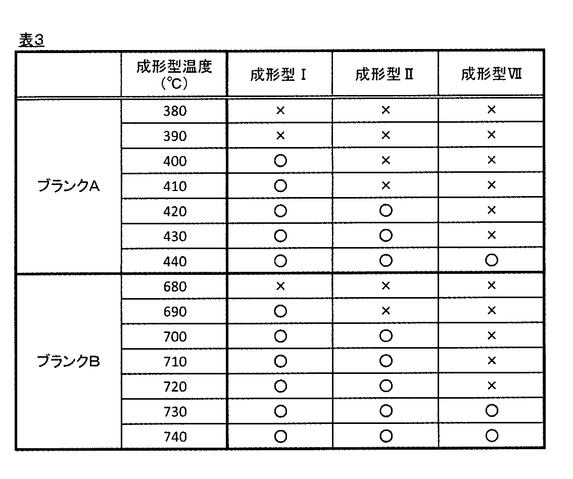
表3に示されるように、本発明の比較例に相当する成形型VIIでは、成形型の温度が低温側にわずかに移行しただけで、成形不良を生じることが確認された。
成形型VIIのように低温側の領域で成形不良を抑止する場合、成形型の温度を高める必要があるが、成形型の温度が高いとガラスと成形型との融着が生じ易くなるとともに、成形後の形状ばらつきが大きくなる。したがって、成形型VIIを用いてレンズブランクを作製することは生産性と品質の低下を招くことがわかった。
これに対し、本発明の成形型IおよびIIでは、成形型の温度が低温側に多少移行しても、良好な成形が可能であることが確認された。
このように、プレス成形可能な温度範囲が広くなったことで、成形型の温度管理を精緻に行う必要がなくなり、生産性が向上し、さらに、比較的低温側の領域でプレス成形しても成形不良が生じないため、成形後の形状ばらつきが小さくなり品質が安定することがわかった。
11… 下型
21… 上型
13,23… 基材
13A,23A… 基材表面
15,25… 酸化物セラミック膜
17,27… 成形面(酸化物セラミック膜表面)
30… 胴型
40a… 軟化したガラス素材
40b… 研磨用ガラス光学素子ブランク
21… 上型
13,23… 基材
13A,23A… 基材表面
15,25… 酸化物セラミック膜
17,27… 成形面(酸化物セラミック膜表面)
30… 胴型
40a… 軟化したガラス素材
40b… 研磨用ガラス光学素子ブランク
Claims (6)
- 少なくとも上型および下型を有し、
大気雰囲気において、軟化したガラス素材をプレス成形して研磨用ガラス光学素子ブランクを製造するために用いる成形型であって、
前記上型および下型の少なくとも一方の成形面は、膜厚が5μm以上の酸化物セラミック膜を有する、成形型。 - 前記酸化物セラミック膜は、シリカ、アルミナ、ジルコニア、チタニア、マグネシア、およびカルシアからなる群から選択される少なくとも1種を含む、請求項1に記載の成形型。
- 前記酸化物セラミック膜は、コロイダルシリカを含む、請求項1または2に記載の成形型。
- 前記酸化物セラミック膜は、50μm以下である、請求項1~3のいずれかに記載の成形型。
- 請求項1~4のいずれかに記載の成形型を用意する工程と、
光学ガラスからなるガラス素材を大気雰囲気下で再加熱した後、軟化した前記ガラス素材を前記成形型でプレス成形するプレス工程と
を含む研磨用ガラス光学素子ブランクの製造方法。 - 請求項5に記載の製造方法によって製造された研磨用ガラス光学素子ブランクを研削する工程と、
前記研削工程を経た研磨用ガラス光学素子ブランクを研磨する工程と
を含む光学素子の製造方法。
Priority Applications (1)
| Application Number | Priority Date | Filing Date | Title |
|---|---|---|---|
| CN201480066195.8A CN105813991B (zh) | 2013-12-12 | 2014-12-02 | 研磨用玻璃光学元件坯料用成型模具、和研磨用玻璃光学元件坯料以及光学元件的制造方法 |
Applications Claiming Priority (2)
| Application Number | Priority Date | Filing Date | Title |
|---|---|---|---|
| JP2013257135A JP6411734B2 (ja) | 2013-12-12 | 2013-12-12 | 研磨用ガラス光学素子ブランク用成形型、並びに、研磨用ガラス光学素子ブランクおよび光学素子の製造方法 |
| JP2013-257135 | 2013-12-12 |
Publications (1)
| Publication Number | Publication Date |
|---|---|
| WO2015087742A1 true WO2015087742A1 (ja) | 2015-06-18 |
Family
ID=53371051
Family Applications (1)
| Application Number | Title | Priority Date | Filing Date |
|---|---|---|---|
| PCT/JP2014/081846 Ceased WO2015087742A1 (ja) | 2013-12-12 | 2014-12-02 | 研磨用ガラス光学素子ブランク用成形型、並びに、研磨用ガラス光学素子ブランクおよび光学素子の製造方法 |
Country Status (3)
| Country | Link |
|---|---|
| JP (1) | JP6411734B2 (ja) |
| CN (1) | CN105813991B (ja) |
| WO (1) | WO2015087742A1 (ja) |
Cited By (1)
| Publication number | Priority date | Publication date | Assignee | Title |
|---|---|---|---|---|
| EP3479955B1 (en) | 2017-11-07 | 2024-07-24 | Satisloh AG | Surfacing station for manufacturing optical elements and related manufacturing facility |
Families Citing this family (1)
| Publication number | Priority date | Publication date | Assignee | Title |
|---|---|---|---|---|
| CN110655322A (zh) * | 2018-06-29 | 2020-01-07 | Hoya株式会社 | 再加热压制用玻璃材料、再加热压制完成的玻璃材料、抛光完成的玻璃、及其制造方法 |
Citations (5)
| Publication number | Priority date | Publication date | Assignee | Title |
|---|---|---|---|---|
| JPS63297223A (ja) * | 1987-05-29 | 1988-12-05 | Fuji Dies Kk | 溶融ガラス成形用工具 |
| JPH02129035A (ja) * | 1988-11-04 | 1990-05-17 | Olympus Optical Co Ltd | 光学素子成形用型 |
| JPH1143334A (ja) * | 1997-07-22 | 1999-02-16 | Minolta Co Ltd | 金型保護膜の製造方法 |
| JP2001089164A (ja) * | 1999-09-22 | 2001-04-03 | Olympus Optical Co Ltd | 光学素子用成形型 |
| JP2009096682A (ja) * | 2007-10-18 | 2009-05-07 | Olympus Corp | 光学素子成形用金型の製造方法、加工方法、及び光学素子成形用金型 |
Family Cites Families (12)
| Publication number | Priority date | Publication date | Assignee | Title |
|---|---|---|---|---|
| JPS63297232A (ja) * | 1987-05-29 | 1988-12-05 | Olympus Optical Co Ltd | ガラス製品の成形用型 |
| JPS6433022A (en) * | 1987-07-27 | 1989-02-02 | Olympus Optical Co | Production of optical element forming die |
| JPH04243923A (ja) * | 1990-12-27 | 1992-09-01 | Olympus Optical Co Ltd | 光学素子成形用型 |
| JPH05116963A (ja) * | 1991-10-24 | 1993-05-14 | Olympus Optical Co Ltd | 光学素子成形用型 |
| JPH10251032A (ja) * | 1997-03-11 | 1998-09-22 | Nippon Steel Corp | ガラス成形金型用合金およびそれから作られたガラス成形金型 |
| JPH11180721A (ja) * | 1997-12-19 | 1999-07-06 | Asahi Optical Co Ltd | モールド成形用金型 |
| JP2003146690A (ja) * | 2001-11-07 | 2003-05-21 | Matsushita Electric Ind Co Ltd | ガラス基板成形用金型、その製造方法およびガラス基板成形方法 |
| EP1604757B1 (en) * | 2004-03-31 | 2008-12-24 | Konica Minolta Opto, Inc. | Manufacturing method of die for optical element molding |
| JP4371048B2 (ja) * | 2004-12-21 | 2009-11-25 | コニカミノルタオプト株式会社 | 光学ガラス成形用金型及び光学ガラス素子 |
| CN101980979B (zh) * | 2008-04-03 | 2014-04-09 | 柯尼卡美能达精密光学株式会社 | 下模及其制造方法、玻璃凝块的制造方法及玻璃成型体的制造方法 |
| WO2010071050A1 (ja) * | 2008-12-18 | 2010-06-24 | コニカミノルタオプト株式会社 | 成形型及びガラス成形体の製造方法 |
| JP5099053B2 (ja) * | 2009-03-13 | 2012-12-12 | コニカミノルタアドバンストレイヤー株式会社 | ガラス成形用金型の製造方法及びガラス成形体の製造方法 |
-
2013
- 2013-12-12 JP JP2013257135A patent/JP6411734B2/ja active Active
-
2014
- 2014-12-02 WO PCT/JP2014/081846 patent/WO2015087742A1/ja not_active Ceased
- 2014-12-02 CN CN201480066195.8A patent/CN105813991B/zh active Active
Patent Citations (5)
| Publication number | Priority date | Publication date | Assignee | Title |
|---|---|---|---|---|
| JPS63297223A (ja) * | 1987-05-29 | 1988-12-05 | Fuji Dies Kk | 溶融ガラス成形用工具 |
| JPH02129035A (ja) * | 1988-11-04 | 1990-05-17 | Olympus Optical Co Ltd | 光学素子成形用型 |
| JPH1143334A (ja) * | 1997-07-22 | 1999-02-16 | Minolta Co Ltd | 金型保護膜の製造方法 |
| JP2001089164A (ja) * | 1999-09-22 | 2001-04-03 | Olympus Optical Co Ltd | 光学素子用成形型 |
| JP2009096682A (ja) * | 2007-10-18 | 2009-05-07 | Olympus Corp | 光学素子成形用金型の製造方法、加工方法、及び光学素子成形用金型 |
Cited By (2)
| Publication number | Priority date | Publication date | Assignee | Title |
|---|---|---|---|---|
| EP3479955B1 (en) | 2017-11-07 | 2024-07-24 | Satisloh AG | Surfacing station for manufacturing optical elements and related manufacturing facility |
| US12551979B2 (en) | 2017-11-07 | 2026-02-17 | Satisloh Ag | Surfacing station for manufacturing optical elements and related manufacturing facility |
Also Published As
| Publication number | Publication date |
|---|---|
| JP6411734B2 (ja) | 2018-10-24 |
| JP2015113262A (ja) | 2015-06-22 |
| CN105813991A (zh) | 2016-07-27 |
| CN105813991B (zh) | 2019-10-01 |
Similar Documents
| Publication | Publication Date | Title |
|---|---|---|
| CN101437766A (zh) | 模压用玻璃坯料及玻璃光学元件的制造方法 | |
| US9868661B2 (en) | Glass lens blank for polishing, manufacturing method therefore, and optical lens manufacturing method | |
| CN1290782C (zh) | 玻璃光学元件的制造方法 | |
| JP6423363B2 (ja) | 研磨用ガラス光学素子ブランク用成形型、研磨用ガラス光学素子ブランクの製造方法および光学素子の製造方法 | |
| CN109250895A (zh) | 光学玻璃非球面透镜成型制造方法及其模具 | |
| JP6411734B2 (ja) | 研磨用ガラス光学素子ブランク用成形型、並びに、研磨用ガラス光学素子ブランクおよび光学素子の製造方法 | |
| JP2006315877A (ja) | 成形体の製造方法および成形中間体の製造方法 | |
| JP5442420B2 (ja) | 精密プレス成形用ガラス素材の肉厚決定方法および製造方法、ならびにガラス光学素子の製造方法 | |
| KR20150041610A (ko) | 유리 성형품 및 그 제조 방법, 광학 소자 블랭크, 그리고 광학 소자 및 그 제조 방법 | |
| JP5756769B2 (ja) | プレス成形用ガラス素材の製造方法およびガラス光学素子の製造方法 | |
| CN104470861B (zh) | 玻璃成型品及其制造方法、光学元件坯料、以及光学元件及其制造方法 | |
| CN205590564U (zh) | 研磨用玻璃透镜坯料 | |
| JP5389517B2 (ja) | ガラス母材の製造方法、精密プレス成形用プリフォームの製造方法、及び、光学素子の製造方法 | |
| CN113511802B (zh) | 玻璃制品生产用软化垫片及其制作方法 | |
| JP2017066018A (ja) | 研磨用ガラスレンズブランク、および光学レンズの製造方法 | |
| CN102344237A (zh) | 一种高温合金玻璃模具 | |
| JPWO2015063888A1 (ja) | 光学ガラス素材、研磨用ガラスレンズブランクおよび光学レンズ、並びに、研磨用ガラスレンズブランクおよび光学レンズの製造方法 | |
| JP2006124214A (ja) | 光学素子の成形方法及び光学素子成形用型 | |
| JPS60176928A (ja) | ガラスレンズのプレス成形用型 | |
| JPH02243524A (ja) | 光学素子のプレス成形方法 | |
| JP2003048723A (ja) | プレス成形方法及びプレス成形装置 | |
| CN107572773A (zh) | 有效降低与模具的粘连性的光学玻璃 | |
| JP2004189565A (ja) | 光学ガラス素子成形型 | |
| JP2002255570A (ja) | ガラスレンズ成形用型及びその製造方法 | |
| JPH02217326A (ja) | 光学部品の成形型 |
Legal Events
| Date | Code | Title | Description |
|---|---|---|---|
| 121 | Ep: the epo has been informed by wipo that ep was designated in this application |
Ref document number: 14869425 Country of ref document: EP Kind code of ref document: A1 |
|
| NENP | Non-entry into the national phase |
Ref country code: DE |
|
| 122 | Ep: pct application non-entry in european phase |
Ref document number: 14869425 Country of ref document: EP Kind code of ref document: A1 |