WO2015087490A1 - オーディオ再生装置及び遊技装置 - Google Patents
オーディオ再生装置及び遊技装置 Download PDFInfo
- Publication number
- WO2015087490A1 WO2015087490A1 PCT/JP2014/005780 JP2014005780W WO2015087490A1 WO 2015087490 A1 WO2015087490 A1 WO 2015087490A1 JP 2014005780 W JP2014005780 W JP 2014005780W WO 2015087490 A1 WO2015087490 A1 WO 2015087490A1
- Authority
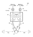
- WO
- WIPO (PCT)
- Prior art keywords
- signal
- sound
- unit
- ear
- listener
- Prior art date
- Legal status (The legal status is an assumption and is not a legal conclusion. Google has not performed a legal analysis and makes no representation as to the accuracy of the status listed.)
- Ceased
Links
Images









Classifications
-
- G—PHYSICS
- G10—MUSICAL INSTRUMENTS; ACOUSTICS
- G10K—SOUND-PRODUCING DEVICES; METHODS OR DEVICES FOR PROTECTING AGAINST, OR FOR DAMPING, NOISE OR OTHER ACOUSTIC WAVES IN GENERAL; ACOUSTICS NOT OTHERWISE PROVIDED FOR
- G10K15/00—Acoustics not otherwise provided for
- G10K15/08—Arrangements for producing a reverberation or echo sound
-
- H—ELECTRICITY
- H04—ELECTRIC COMMUNICATION TECHNIQUE
- H04S—STEREOPHONIC SYSTEMS
- H04S7/00—Indicating arrangements; Control arrangements, e.g. balance control
- H04S7/30—Control circuits for electronic adaptation of the sound field
- H04S7/305—Electronic adaptation of stereophonic audio signals to reverberation of the listening space
-
- G—PHYSICS
- G10—MUSICAL INSTRUMENTS; ACOUSTICS
- G10K—SOUND-PRODUCING DEVICES; METHODS OR DEVICES FOR PROTECTING AGAINST, OR FOR DAMPING, NOISE OR OTHER ACOUSTIC WAVES IN GENERAL; ACOUSTICS NOT OTHERWISE PROVIDED FOR
- G10K11/00—Methods or devices for transmitting, conducting or directing sound in general; Methods or devices for protecting against, or for damping, noise or other acoustic waves in general
- G10K11/18—Methods or devices for transmitting, conducting or directing sound
- G10K11/26—Sound-focusing or directing, e.g. scanning
- G10K11/34—Sound-focusing or directing, e.g. scanning using electrical steering of transducer arrays, e.g. beam steering
- G10K11/341—Circuits therefor
- G10K11/346—Circuits therefor using phase variation
-
- H—ELECTRICITY
- H04—ELECTRIC COMMUNICATION TECHNIQUE
- H04R—LOUDSPEAKERS, MICROPHONES, GRAMOPHONE PICK-UPS OR LIKE ACOUSTIC ELECTROMECHANICAL TRANSDUCERS; ELECTRIC HEARING AIDS; PUBLIC ADDRESS SYSTEMS
- H04R29/00—Monitoring arrangements; Testing arrangements
- H04R29/001—Monitoring arrangements; Testing arrangements for loudspeakers
- H04R29/002—Loudspeaker arrays
-
- H—ELECTRICITY
- H04—ELECTRIC COMMUNICATION TECHNIQUE
- H04R—LOUDSPEAKERS, MICROPHONES, GRAMOPHONE PICK-UPS OR LIKE ACOUSTIC ELECTROMECHANICAL TRANSDUCERS; ELECTRIC HEARING AIDS; PUBLIC ADDRESS SYSTEMS
- H04R3/00—Circuits for transducers
- H04R3/12—Circuits for transducers for distributing signals to two or more loudspeakers
-
- H—ELECTRICITY
- H04—ELECTRIC COMMUNICATION TECHNIQUE
- H04R—LOUDSPEAKERS, MICROPHONES, GRAMOPHONE PICK-UPS OR LIKE ACOUSTIC ELECTROMECHANICAL TRANSDUCERS; ELECTRIC HEARING AIDS; PUBLIC ADDRESS SYSTEMS
- H04R5/00—Stereophonic arrangements
- H04R5/04—Circuit arrangements, e.g. for selective connection of amplifier inputs/outputs to loudspeakers, for loudspeaker detection, or for adaptation of settings to personal preferences or hearing impairments
-
- H—ELECTRICITY
- H04—ELECTRIC COMMUNICATION TECHNIQUE
- H04S—STEREOPHONIC SYSTEMS
- H04S7/00—Indicating arrangements; Control arrangements, e.g. balance control
- H04S7/30—Control circuits for electronic adaptation of the sound field
- H04S7/307—Frequency adjustment, e.g. tone control
-
- H—ELECTRICITY
- H04—ELECTRIC COMMUNICATION TECHNIQUE
- H04R—LOUDSPEAKERS, MICROPHONES, GRAMOPHONE PICK-UPS OR LIKE ACOUSTIC ELECTROMECHANICAL TRANSDUCERS; ELECTRIC HEARING AIDS; PUBLIC ADDRESS SYSTEMS
- H04R2203/00—Details of circuits for transducers, loudspeakers or microphones covered by H04R3/00 but not provided for in any of its subgroups
- H04R2203/12—Beamforming aspects for stereophonic sound reproduction with loudspeaker arrays
-
- H—ELECTRICITY
- H04—ELECTRIC COMMUNICATION TECHNIQUE
- H04R—LOUDSPEAKERS, MICROPHONES, GRAMOPHONE PICK-UPS OR LIKE ACOUSTIC ELECTROMECHANICAL TRANSDUCERS; ELECTRIC HEARING AIDS; PUBLIC ADDRESS SYSTEMS
- H04R5/00—Stereophonic arrangements
- H04R5/02—Spatial or constructional arrangements of loudspeakers
-
- H—ELECTRICITY
- H04—ELECTRIC COMMUNICATION TECHNIQUE
- H04S—STEREOPHONIC SYSTEMS
- H04S2400/00—Details of stereophonic systems covered by H04S but not provided for in its groups
- H04S2400/01—Multi-channel, i.e. more than two input channels, sound reproduction with two speakers wherein the multi-channel information is substantially preserved
-
- H—ELECTRICITY
- H04—ELECTRIC COMMUNICATION TECHNIQUE
- H04S—STEREOPHONIC SYSTEMS
- H04S2420/00—Techniques used stereophonic systems covered by H04S but not provided for in its groups
- H04S2420/07—Synergistic effects of band splitting and sub-band processing
-
- H—ELECTRICITY
- H04—ELECTRIC COMMUNICATION TECHNIQUE
- H04S—STEREOPHONIC SYSTEMS
- H04S7/00—Indicating arrangements; Control arrangements, e.g. balance control
- H04S7/30—Control circuits for electronic adaptation of the sound field
-
- H—ELECTRICITY
- H04—ELECTRIC COMMUNICATION TECHNIQUE
- H04S—STEREOPHONIC SYSTEMS
- H04S7/00—Indicating arrangements; Control arrangements, e.g. balance control
- H04S7/30—Control circuits for electronic adaptation of the sound field
- H04S7/302—Electronic adaptation of stereophonic sound system to listener position or orientation
- H04S7/303—Tracking of listener position or orientation
Definitions
- the present disclosure relates to an audio playback device that localizes sound to the listener's ears, and a game device that produces the enjoyment of the game through sound effects.
- Patent Document 2 a technique of providing a virtual sound field to a listener by using a speaker array is also known (see, for example, Patent Document 2).
- JP-A-9-233599 JP 2012-70135 A Japanese Patent No. 4840480
- the sweet spot can be widened by the technology for virtually generating the sound field using the speaker array.
- it is necessary to cross the plane waves output from the speaker array at the listener's position. For this reason, it is necessary to arrange the speaker arrays so as to intersect with each other, and there is a problem that the arrangement of the speakers is restricted.
- the present disclosure provides an audio reproduction device that can localize a predetermined sound at the listener's ear without using binaural recording and relaxes restrictions on the arrangement of speakers (speaker elements).
- an audio playback device that localizes sound at a listener's ear, and includes N audio signals (N is an integer of 3 or more).
- a signal processing unit that converts the signal into channel signals; and a speaker array that includes at least N speaker elements that output the N channel signals as reproduced sounds, respectively, and the signal processing unit is output from the speaker array.
- a cancellation unit that performs processing, and the N channel signals include the audio signal processed by the beamform processing. It is, and a signal obtained by being the cancellation process.
- the cancel unit performs the cancel process for every N / 2 pairs with respect to N signals generated by performing the beamforming process on the audio signal.
- a certain crosstalk cancellation process may be performed to generate the N channel signals.
- the filter (constant) used for the crosstalk cancellation process can be obtained only from the geometric positional relationship between the set of two speaker elements and the listener, so the filter used for the crosstalk cancellation process can be easily defined. can do.
- the cancel unit is a crosstalk cancel process which is the cancel process based on a transfer function from the input signal input to the beam form unit being output as playback sound from the speaker array to the listener's ear. May be performed on the audio signal, and the beamform unit may perform the beamform process on the audio signal subjected to the crosstalk cancellation process to generate the N channel signals.
- the beamform unit corresponds to each of the N speaker elements, and a band division filter that generates a band signal that is a signal obtained by dividing the audio signal for each predetermined frequency band, and the generated band signal. Filtering is performed on the distribution unit that distributes to the channel, and the distributed band signal according to the position of the speaker element to which the band signal is distributed and the frequency band of the band signal, to obtain a filtered signal
- the band division filter divides the audio signal into a high-frequency band signal and a low-frequency band signal, and the position / band-specific filter includes an H of the distributed N high-frequency band signals.
- H is a positive integer equal to or less than N
- L L is higher than H
- the filtering process is performed on the high-frequency band signals (H is a positive integer equal to or less than N)
- L L is higher than H) of the distributed N low-frequency band signals. May be applied to the low-frequency band signal of a small positive integer).
- the filter for each position / band may be arranged such that the amplitude of the filtered signal of a specific channel is larger than the amplitude of the filtered signal of the channel adjacent to the specific channel.
- the filtering process may be applied to the above.
- the signal processing unit may further include a bass emphasizing unit that adds a harmonic component of a low frequency part of the audio signal before the cancellation process to the audio signal.
- An audio reproduction device is an audio reproduction device that localizes sound at a listener's ear, and includes a signal processing unit that converts an audio signal into a left channel signal and a right channel signal, and the left channel A left speaker element that outputs a signal as reproduced sound, and a right speaker element that outputs the right channel signal as reproduced sound, and the signal processing unit converts a harmonic component of a low frequency portion of the audio signal into the audio signal.
- the bass enhancement unit to be added and the playback sound output from the right speaker element are suppressed from reaching the position of the listener's left ear, and the playback sound output from the left speaker element is the right ear of the listener.
- Cancel processing for suppressing arrival at a position is performed on the audio signal to which the harmonic component is added, and the left channel Nos and and a cancellation unit for generating the right channel signals.
- An audio playback device includes a signal processing unit that converts an audio signal into a left channel signal and a right channel signal, a left speaker element that outputs the left channel signal as playback sound, and the right channel.
- a right speaker element that outputs a signal as a reproduction sound, and the signal processing unit localizes the sound of the audio signal to a predetermined position, and is one ear of a listener facing the left speaker element and the right speaker element.
- a filter designed to emphasize and perceive sound at a position, and converts the audio signal processed by the filter into the left channel signal and the right channel signal, and the predetermined position is a top surface The position of the listener and the position of one of the left speaker element and the right speaker element when viewed. Of the two areas separated by a straight line connecting the speaker elements may be located in a position side region of the one ear.
- the signal processing unit further performs a cancellation process on the audio signal to suppress the sound of the audio signal from being perceived by the other ear of the listener, and the left channel signal and the right channel signal
- the straight line connecting the predetermined position and the listener position is substantially parallel to the straight line connecting the left speaker element and the right speaker element. Also good.
- An audio reproduction device is an audio reproduction device that localizes sound at a listener's ear, and includes a signal processing unit that converts an audio signal into a left channel signal and a right channel signal, and the left channel A left speaker element that outputs a signal as a reproduced sound and a right speaker element that outputs the right channel signal as a reproduced sound, and the signal processing unit receives the virtual sound source from a virtual sound source placed beside the listener.
- a first transfer function of sound reaching the first ear of the listener close to the sound source; a second transfer function of sound reaching the second ear opposite to the first ear from the virtual sound source; Filter processing using a first parameter multiplied by one transfer function and a second parameter multiplied by the second transfer function may be performed.
- the signal processing unit is configured such that when the first parameter is ⁇ , the second parameter is ⁇ , and the ratio ( ⁇ / ⁇ ) of the first parameter to the second parameter is R, (i) When the distance between the virtual sound source and the listener is the first distance, the value of R is set to a first value in the vicinity of 1, and (ii) the virtual sound source and the listener are more than the first distance. When the second distance is close, the value of R may be set to a second value that is larger than the first value.
- the signal processing unit is configured such that when the first parameter is ⁇ , the second parameter is ⁇ , and the ratio ( ⁇ / ⁇ ) of the first parameter to the second parameter is R, (i) When the position of the virtual sound source is approximately 90 degrees with respect to the front direction of the listener, the value of R is set to a value greater than 1, and (ii) the position of the virtual sound source is approximately equal to the front direction of the listener.
- the value of R may be made closer to 1 as it deviates from 90 degrees.
- a gaming device outputs an acoustic signal corresponding to an expected value set by the expected value setting unit configured to set an expected value for the player to win the game, and an expected value set by the expected value setting unit.
- the sound signal processed by the filter having a stronger crosstalk cancellation performance than when the expected value is small is output, so that the player expects to win the game by the sound heard at the ear.
- a feeling can be felt higher.
- the player's expectation of winning the game can be produced by a whisper or sound effect heard at the player's ears, the player's expectation of winning the game can be further enhanced.
- the acoustic processing unit reaches from the virtual sound source placed on the side of the player to the first ear of the player close to the virtual sound source.
- the filter processing using the second parameter multiplied by the two transfer function the first parameter and the second parameter are determined according to the expected value set by the expected value setting unit, thereby canceling the crosstalk. You may output the acoustic signal processed with the filter with strong performance.
- the level of expectation that the player can win the game can be produced by the level of the whisper or sound effect that can be heard at the player's ear.
- the sound processing unit may be more effective when the expected value set by the expected value setting unit is larger than the threshold than when the expected value is smaller than the threshold.
- the first parameter and the second parameter may be determined so that a difference between the first parameter and the second parameter becomes large.
- the larger the expected value the larger the sound that can be heard by one ear and the smaller the sound that can be heard by the other ear.
- the level of expectation that a player can win the game It can be produced by a whisper or sound effect that can be heard.
- the acoustic processing unit has a first acoustic signal processed by a filter having a strong crosstalk cancellation performance, and a crosstalk cancellation performance higher than that of the first acoustic signal.
- An accumulator that stores the second acoustic signal processed by the weak filter; and when the expected value set by the expected value setting unit is greater than the threshold, the first acoustic signal is selected and output, and the expected And a selection unit that selects and outputs the second acoustic signal when the expected value set by the value setting unit is smaller than the threshold value.
- a gaming device includes an expected value setting unit that sets an expected value for a player to win a game, and an acoustic signal corresponding to the expected value set by the expected value setting unit.
- An acoustic processing unit for outputting, and at least two sound output units for outputting an acoustic signal output from the acoustic processing unit, wherein the acoustic processing unit has an expected value set by the expected value setting unit.
- a reverberation component larger than when the expected value is smaller than the threshold value may be added to the acoustic signal and output.
- the expected value setting unit includes a probability setting unit that sets a probability of winning the game, a timer unit that measures the duration of the game, and the probability You may provide the expected value control part which sets the said expected value based on the probability set by the setting part, and the continuation time measured by the said timer part.
- the audio reproduction device of the present disclosure it is possible to localize a predetermined sound at the listener's ear without using binaural recording, and the restriction on the arrangement of the speaker array is eased.
- FIG. 1 is a diagram illustrating an example of a dummy head.
- FIG. 2 is a diagram for explaining general crosstalk cancellation processing.
- FIG. 3 is a diagram illustrating a wavefront of sound output from two speakers and a position of a listener.
- FIG. 4 is a diagram illustrating the relationship between the wavefront of the plane wave output from the speaker array and the position of the listener.
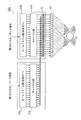
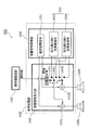
- FIG. 5 is a diagram showing the configuration of the audio playback apparatus according to the first embodiment.
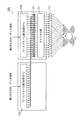
- FIG. 6 is a diagram showing the configuration of the beamform unit.
- FIG. 7 is a flowchart of the operation of the beamform unit.
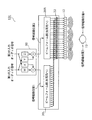
- FIG. 8 is a diagram illustrating the configuration of the cancel unit.
- FIG. 9 is a diagram illustrating a configuration of the crosstalk canceling unit.
- FIG. 1 is a diagram illustrating an example of a dummy head.
- FIG. 2 is a diagram for explaining general crosstalk cancellation processing.
- FIG. 3 is a diagram illustrating a
- FIG. 10 is a diagram illustrating an example of the configuration of an audio playback device when there are two input audio signals.
- FIG. 11 is a diagram illustrating another example of the configuration of the audio playback device when there are two input audio signals.
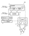
- FIG. 12 is a diagram illustrating an example of a configuration of an audio reproduction device in a case where beamform processing is performed after crosstalk cancellation processing.
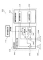
- FIG. 13 is a diagram illustrating a configuration of an audio reproduction device according to the second embodiment.
- FIG. 14 is a diagram illustrating a configuration of an audio reproduction device according to the third embodiment.
- FIG. 15 is a diagram showing a configuration of an audio reproduction device when two input audio signals according to Embodiment 3 are used.
- FIG. 16 is a diagram showing a configuration of an audio reproduction device when two input audio signals according to Embodiment 4 are used.
- FIG. 17 is a diagram illustrating the position of the virtual sound source in the direction of approximately 90 degrees of the listener according to the fourth embodiment.
- FIG. 18 is a diagram illustrating the position of the virtual sound source on the side of the listener according to the fourth embodiment.
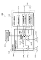
- FIG. 19 is a block diagram illustrating an example of a configuration of a gaming device according to the fifth embodiment.
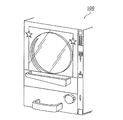
- FIG. 20 is an overview perspective view showing an example of a gaming apparatus according to the fifth embodiment.
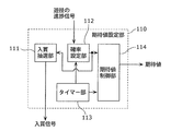
- FIG. 21 is a block diagram illustrating an example of a configuration of an expected value setting unit according to the fifth embodiment.
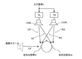
- FIG. 22 is a diagram illustrating a signal flow until the acoustic signal according to Embodiment 5 reaches the player's ear.
- FIG. 23 is a diagram illustrating another example of the signal flow until the acoustic signal according to Embodiment 5 reaches the player's ear.
- FIG. 24 is a block diagram showing another example of the configuration of the gaming device according to the fifth embodiment.
- FIG. 25 is a block diagram showing another example of the configuration of the gaming apparatus according to the fifth embodiment.
- FIG. 26 is a block diagram illustrating an example of a configuration of a gaming device according to the sixth embodiment.
- FIG. 27 is a block diagram illustrating an example of a configuration of a gaming device according to a modification of the sixth embodiment.
- Binaural recording is to record sound waves that reach both ears of a human as it is by picking up sound by using microphones prepared in both ears of a so-called dummy head as shown in FIG. The listener can perceive the spatial sound at the time of recording by listening to the playback sound of the audio signal recorded in this way using headphones.
- FIG. 2 is a diagram for explaining a general crosstalk cancellation process.
- the transfer function of the sound from the left channel speaker SP-L to the listener's left ear is expressed as hFL
- the transfer function of the sound from the left channel speaker SP-L to the listener's right ear is expressed as hCL.
- the transfer function of the sound from the right channel speaker SP-R to the listener's right ear is expressed as hFR
- the transfer function of the sound from the right channel speaker SP-R to the listener's left ear is expressed as hCR.
- the matrix M of the transfer function is the matrix shown in FIG.
- the signal recorded at the left ear of the dummy head is expressed as XL
- the signal recorded at the right ear of the dummy head is expressed as XR
- the signal reaching the listener's left ear is ZL
- the listener's right ear is expressed as ZR.
- the reproduced sound of the signal [YL, YR] obtained by multiplying the input signal [XL, XR] by the inverse matrix M ⁇ 1 of the matrix M is output from the left channel speaker SP-L and the right channel speaker SP-R.
- a signal obtained by multiplying the signal [YL, YR] by the matrix M arrives at the listener's ear.
- the input signals [XL, XR] are signals [ZL, ZR] that reach the left and right ears of the listener. That is, the crosstalk component (the sound reaching the listener's right ear among the sound waves output from the left channel speaker SP-L and the left side of the listener among the sound waves output from the right channel speaker SP-R. (Sound reaching the ear) is canceled.
- Such a method is widely known as a crosstalk cancellation process.
- FIG. 3 is a diagram illustrating a wavefront of sound output from two speakers and a position of a listener.
- a sound having a concentric wavefront is output from each speaker.
- the broken-line circle is the wavefront of the sound output from the right speaker in FIG.
- the solid circle is the wavefront of the sound output from the left speaker in FIG.
- the difference between the arrival time of the sound wavefront from the left speaker and the arrival time of the sound wavefront from the right speaker at the position of the listener A and the position of the listener B is different. Therefore, in FIG. 3, if the transfer characteristic is set so that the three-dimensional sound field can be most effectively perceived at the position of the listener A, the actual position obtained at the position of the listener B is higher than the position of the listener A. The feeling decreases.
- the technique for canceling the crosstalk of the sound output from the two speakers has a problem that the so-called sweet spot is narrow.
- the sweet spot can be widened.
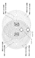
- FIG. 4 is a diagram showing the relationship between the wavefront of the plane wave output from the speaker array and the position of the listener. As shown in FIG. 4, a plane wave traveling perpendicular to the wavefront is output from each speaker array. In FIG. 4, the broken line indicates the wavefront of the plane wave output from the right speaker array, and the solid line indicates the wavefront of the plane wave output from the left speaker array.
- the difference between the arrival time of the sound wavefront from the left speaker and the arrival time of the sound wavefront from the right speaker at the position of the listener A and the position of the listener B is the same. It is. Therefore, in FIG. 4, if the transfer characteristic is set so that the three-dimensional sound field can be most effectively perceived at the position of the listener A, the three-dimensional sound field can be effectively perceived even at the position of the listener B. In FIG. 4, it can be said that the sweet spot is wider than in FIG.
- the present disclosure has been made in view of such a problem, and provides an audio reproduction device that does not use binaural recording and relaxes restrictions on the arrangement of speakers (speaker elements).
- the present disclosure provides an audio playback device capable of localizing a predetermined sound at the listener's ear from, for example, a speaker array arranged in a straight line.
- Patent Document 1 discloses means for solving this problem.
- a plurality of crosstalk cancellation signal generation filters must be connected in multiple stages, and a huge amount of calculation is required. Is a problem.
- the present disclosure has also been made in view of such a problem, and provides an audio reproduction device that can recover a low frequency signal lost by a crosstalk cancellation process with a small amount of calculation.
- FIG. 5 is a diagram showing the configuration of the audio playback apparatus according to the first embodiment.
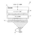
- the audio playback device 10 includes a signal processing unit 11 and a speaker array 12.
- the signal processing unit 11 includes a beamform unit 20 and a cancel unit 21.
- the signal processing unit 11 converts the input audio signal into N channel signals.
- N 20
- N may be an integer of 3 or more.
- the N channel signals are signals obtained by subjecting the input audio signal to beamform processing and cancellation processing, which will be described later.
- the speaker array 12 includes at least N speaker elements that respectively reproduce N channel signals (output as reproduced sounds).
- the speaker array 12 is composed of 20 speaker elements.
- the beamform unit 20 performs beamform processing for resonating the reproduced sound output from the speaker array 12 at the position of one ear of the listener 13.
- the cancel unit 21 performs a cancel process for suppressing the reproduction sound of the input audio signal output from the speaker array 12 from reaching the position of the other ear of the listener 13.
- the beamform unit 20 and the cancel unit 21 constitute a signal processing unit 11.
- the beamform unit 20 performs beamform processing on the input audio signal so that the reproduced sound output from the speaker array 12 resonates at the position of one ear of the listener.
- Any conventionally known method may be used as the beam forming method.
- a method as described in Non-Patent Document 1 can be used.
- FIG. 6 is a diagram showing a configuration of the beamform unit 20 according to the first embodiment.
- the canceling unit 21 in FIG. 5 is not illustrated in order to describe the beam forming unit 20 as a center.
- the beamform unit 20 shown in FIG. 6 corresponds to the beamform unit 20 shown in FIG.
- the beamform unit 20 includes a band division filter 30, a distribution unit 31, a position / band-specific filter group 32, and a band synthesis filter group 33.
- the band division filter 30 divides the input audio signal into band signals of a plurality of frequency bands. That is, the band division filter 30 generates a plurality of band signals obtained by dividing the input audio signal for each predetermined frequency band.
- the distributing unit 31 distributes each band signal to a corresponding channel of each speaker element constituting the speaker array 12.
- the filter group 32 classified by position / band performs a filtering process on each distributed band signal according to the channel to which the band signal is distributed (the position of the speaker element) and the frequency band of the band signal.
- the position / band-specific filter group 32 outputs a signal after filtering (filtered signal).
- the band synthesis filter group 33 performs band synthesis on the filtered signals output from the position / band-specific filter group 32 for each position.
- FIG. 7 is a flowchart of beamform processing according to the first embodiment.
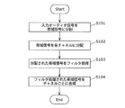
- the input audio signal is divided into band signals of a plurality of frequency bands by the band dividing filter 30 (S101).
- the input audio signal is divided into two, a high-frequency signal and a low-frequency signal, but the input audio signal may be divided into three or more.
- the low-frequency signal is a signal in a band of a predetermined frequency or less in the input audio signal
- the high-frequency signal is a signal in a band larger than the predetermined frequency in the input audio signal.
- the distribution unit 31 distributes each band signal (high frequency signal and low frequency signal) to 20 channels corresponding to each of the 20 speaker elements constituting the speaker array 12 (S102).
- Each distributed band signal is filtered by the position / band-specific filter group 32 according to the channel to which the band signal is distributed (the position of the speaker element) and the frequency band of the band signal (S103). .
- the filtering process will be described in detail.
- the position / band-specific filter group 32 includes a low-frequency signal processing unit 34 and a high-frequency signal processing unit 35.
- the low frequency signal is processed by the low frequency signal processing unit 34
- the high frequency signal is processed by the high frequency signal processing unit 35.
- Each of the low-frequency signal processing unit 34 and the high-frequency signal processing unit 35 executes at least delay processing and amplitude increase / decrease processing.
- Each of the low-frequency signal processing unit 34 and the high-frequency signal processing unit 35 distributes each band signal so that a sound wave having a strong (high) sound pressure level is formed at the right ear of the listener 13 shown in FIG. Process.
- the low-frequency signal processing unit 34 and the high-frequency signal processing unit 35 are the most similar to each band signal distributed to the channel closest to the right ear of the listener 13 (the speaker element located closest). Delay processing giving a large delay is performed, and amplification processing having the largest gain is performed.
- the low-frequency signal processing unit 34 and the high-frequency signal processing unit 35 gradually give a small delay as the channel moves left and right from the channel closest to the right ear of the listener 13 and a small gain amplification ( (Attenuation).
- the low-frequency signal processing unit 34 and the high-frequency signal processing unit 35 perform delay processing that gives a larger delay to each band signal distributed to the channel closer to the position of the listener's 13 right ear, and Performs amplification processing that gives a large gain.
- the low-frequency signal processing unit 34 and the high-frequency signal processing unit 35 distribute such that the amplitude of the filtered signal of the specific channel is larger than the amplitude of the filtered signal of the channels adjacent to the specific channel.
- a filtering process is performed on the band signal. That is, the beamform unit 20 performs control such that sound (sound wave) output from each speaker element resonates at the position of the right ear of the listener 13.
- the low frequency signal does not need to be reproduced in all speaker elements.
- resonance between sound waves output from adjacent speaker elements is larger than that of the high frequency signal. Therefore, in order to balance perceptually between the high frequency component and the low frequency component, the low frequency signal may not be output from all the speaker elements that output the high frequency signal.
- H is a positive integer equal to or less than N
- the low-frequency signal processing unit 34 may perform filtering on L low-frequency signals (L is a positive integer smaller than H) among the distributed N low-frequency signals.
- L is a positive integer smaller than H
- the band synthesis filter group 33 performs band synthesis of the filtered signal output from the position / band-specific filter group 32 for each channel (S104).
- the band synthesis filter group 33 performs band synthesis on the filtered signals belonging to the same channel (the filtered signal obtained by filtering the low-frequency signal and the filtered signal obtained by filtering the high-frequency signal).
- the band synthesis filter group 33 includes a plurality of (20) band synthesis filters 36 for each channel, and the band synthesis filter 36 synthesizes the filtered signal of the channel (the position of the speaker element). To generate a time axis signal.
- FIG. 8 is a diagram illustrating a configuration of the cancel unit 21 according to the first embodiment.
- FIG. 9 is a diagram illustrating a configuration of the crosstalk canceling unit according to the first embodiment.
- the beamformer 20 in FIG. 5 is not shown in order to explain mainly the canceler 21.
- the beamform unit 20 corresponds to the beamform unit 20 in FIG. 5
- the cancel unit 21 corresponds to the cancel unit 21 in FIG. 5.
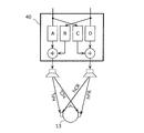
- Each of the crosstalk cancellation units 40 has the configuration shown in FIG.
- the crosstalk cancellation unit 40 cancels the crosstalk of one pair of channels.
- a pair of channels is a channel having a symmetrical positional relationship with respect to the middle of the direction in which the straight line extends among the linearly arranged speaker elements.
- the crosstalk cancellation unit 40 sets transfer functions A, B, C, and D to the signals (two signals corresponding to one pair of channels) input to the crosstalk cancellation unit 40 (cancellation unit 21) as shown in FIG. Multiply as shown in
- the crosstalk cancellation unit 40 adds the signals after multiplication as shown in FIG. 9, and the added signal (channel signal) is output (reproduced) from the corresponding speaker element. As a result, the crosstalk component between both ears due to the sound emitted from the speakers of one pair of channels is canceled. This is as described in the section “Knowledge on which this disclosure is based”.
- the method for canceling the crosstalk may be another method.
- Such crosstalk cancellation processing is performed for N / 2 pairs as shown in FIG.
- the N channel signals generated in this way are output (reproduced) from the respective speaker elements of the speaker array 12.
- the sound wave having a strong sound pressure level (amplitude) localized at the right ear of the listener 13 by the beamform process is suppressed from reaching the left ear of the listener 13. Therefore, the perceptual psychology of the listener 13 that “the input audio signal is reproduced at the right ear” can be enhanced.
- the binaural recording is not used, and a predetermined sound is localized at the listener's ear only from the speaker array 12 arranged in a straight line. Is possible. That is, according to the audio reproduction device 10 according to Embodiment 1, the listener 13 can sufficiently enjoy a three-dimensional sound field even in a space where speakers cannot be arranged three-dimensionally.
- the sound there is one input audio signal, and the case where sound is localized at the right ear of the listener has been described. However, the sound may be localized at the left ear, or the input audio signal may be localized. May be plural. When there are a plurality of input audio signals, the sounds of the plurality of input audio signals may be localized at different ears of the listener 13.
- FIG. 10 is a diagram showing an example of the configuration of an audio playback device when there are two input audio signals. Two signals of a first input audio signal and a second input audio signal are input to the audio playback device 10a shown in FIG.
- beamform processing and crosstalk cancellation processing are performed on each of the first input audio signal and the second input audio signal.
- the first audio signal is subjected to beamform processing by the beamform unit 20L so that the reproduced sound is localized at the left ear of the listener 13, and is further subjected to crosstalk cancellation processing by the cancel unit 21L.
- the second audio signal is subjected to beamform processing by the beamform unit 20R so that the reproduced sound is localized at the right ear of the listener 13, and is further subjected to crosstalk cancellation processing by the cancel unit 21R.
- the adder 22 adds the signals after the beamform processing and the crosstalk cancellation processing for each channel, and outputs (reproduces) the signals after the addition from each speaker element constituting the speaker array 12.
- the addition process may be performed before the cancel process of the cancel unit 21 as in the audio playback device 10b illustrated in FIG.
- the addition processing is performed after the filtered signal (the band signal after the processing of the position / band-specific filter group 32 in the beamform units 20L and 20R and before the processing of the band synthesis filter group 33). May be performed.
- the crosstalk cancellation process is performed after the beamform process. That is, the cancel unit 21 performs a crosstalk cancellation process for each N / 2 pairs on N signals generated by performing beamform processing on the input audio signal.
- the crosstalk cancellation process may be performed first, and then the beamform process may be performed.
- FIG. 12 is a diagram showing an example of the configuration of an audio playback device when beamform processing is performed after crosstalk cancellation processing. Note that two input audio signals are input to the audio playback device 10c shown in FIG.
- the cancel unit 50 of the audio playback device 10c multiplies two input audio signals by four transfer functions (W, X, Y, Z).
- W transfer functions
- X X
- Y Y
- Z transfer functions
- Signal path position 1 and signal path position 2 are positions in the middle of signal processing (immediately before beamform processing).
- the signal path position 3 is the position of the listener's left ear, and the signal path position 4 is the position of the listener's right ear.
- the transfer function from signal path position 1 to signal path position 3 is hBFL
- the transfer function from signal path position 1 to signal path position 4 is hBCL
- the transfer function from signal path position 2 to signal path position 3 is hBCR
- the transfer function from signal path position 2 to signal path position 4 is represented by hBFR
- the relationship between the matrix M and the elements W, X, Y, and Z of the inverse matrix M ⁇ 1 of the matrix M is as follows.
- a transfer function of a signal input to the beamform units 20L and 20R is measured or calculated in advance.
- the transfer function is a transfer function from when the signals input to the beamform units 20L and 20R are subjected to beamform processing, to be output from the speaker array 12 and finally to the listener's ear. .
- an inverse matrix of a matrix having these transfer functions as elements is obtained, and a crosstalk cancellation process is performed before the beamform process using the obtained inverse matrix. That is, the crosstalk cancellation process is performed after the beamform process.
- the cancel unit 50 performs the crosstalk cancellation process based on the transfer function from the time when the input signals input to the beamform units 20L and 20R are output as the reproduced sound from the speaker array 12 to the listener's ear. To the input audio signal.
- the beamform units 20L and 20R perform beamform processing on the input audio signal that has been subjected to the crosstalk cancellation processing, and generate N channel signals.
- the crosstalk cancellation processing is performed before the beamform processing, so that the crosstalk cancellation processing can be performed for one pair of signals, thereby reducing the amount of calculation. Is done.
- FIG. 13 is a diagram illustrating a configuration of an audio reproduction device according to the second embodiment.
- the audio reproduction device 10 d includes a signal processing unit (cancellation unit 61, bass enhancement unit 62 and bass enhancement unit 63), a crosstalk cancellation filter setting unit 66, and a bass component extraction filter setting unit 67. And a left speaker element 68 and a right speaker element 69.
- the bass enhancement unit 62 includes a bass component extraction unit 64 and a harmonic component generation unit 65.
- the bass enhancement unit 63 also includes a bass component extraction unit and a bass component generation unit, but illustration and description thereof are omitted.
- the signal processing unit includes a cancel unit 61, a bass enhancement unit 62, and a bass enhancement unit 63.
- the signal processing unit converts the first audio signal and the second audio signal into a left channel signal and a right channel signal.
- the left speaker element 68 outputs the left channel signal as reproduced sound.
- the right speaker element 69 outputs the right channel signal as reproduced sound.
- the cancel unit 61 performs a cancellation process on the first input audio signal to which the harmonic component is added by the bass emphasis unit 62 and the second input audio signal to which the harmonic component is added by the bass enhancement unit 63.
- a left channel signal and a right channel signal are generated.
- the canceling process means that the reproduced sound output from the right speaker element 69 is prevented from reaching the left ear of the listener 13 and the reproduced sound output from the left speaker element 68 is reached to the right ear of the listener 13. It is a process to suppress.
- the bass enhancement unit 62 adds the harmonic component of the low frequency part of the first input audio signal to the first input audio signal.
- the bass enhancement unit 63 adds the harmonic component of the low frequency part of the second input audio signal to the second input audio signal.
- the bass component extraction unit 64 extracts a low frequency part (bass component) emphasized by the bass enhancement unit 62.
- the harmonic component generation unit 65 generates a harmonic component of the bass component extracted by the bass component extraction unit 64.
- the crosstalk cancellation filter setting unit 66 sets the filter coefficient of the crosstalk cancellation filter built in the cancellation unit 61.
- the bass component extraction filter setting unit 67 sets the filter coefficient of the bass component extraction filter built in the bass component extraction unit 64.
- bass enhancement processing and cancellation processing are performed on two input audio signals (first input audio signal and second input audio signal). However, only one input audio signal is used. There may be.
- the first input audio signal and the second input audio signal are input to the bass enhancement unit 62 and the bass enhancement unit 63, respectively.
- the bass enhancement unit 62 and the bass enhancement unit 63 are bass enhancement processing units using a so-called missing fundamental phenomenon.
- the bass emphasizing units 62 and 63 perform signal processing using a missing fundamental phenomenon in order to recover the bass component of the first and second input audio signals attenuated by the crosstalk cancellation processing. Do.
- the bass component extraction unit 64 incorporated in each of the bass enhancement units 62 and 63 extracts a signal in a frequency band that is attenuated by the crosstalk cancellation process. Then, the harmonic component generation unit 65 generates a harmonic component of the bass component extracted by the bass component extraction unit 64.
- the harmonic component generation method of the bass component extraction unit 64 may be any conventionally known method.
- the signals processed by the bass emphasis units 62 and 63 are input to the cancel unit 61 and subjected to crosstalk cancellation processing.
- the crosstalk cancellation processing is the same as the processing described in the section “Knowledge on which the present disclosure is based” and the first embodiment.
- the filter coefficient of the crosstalk cancellation filter used in the cancel unit 61 varies depending on the speaker interval, the characteristics of the speaker, the positional relationship between the speaker and the listener, and the like. Therefore, an appropriate set value of the filter coefficient is set from the crosstalk cancellation filter setting unit 66.
- the low-frequency component extraction filter coefficient is set from the low-frequency component extraction filter setting unit 67.
- the low-frequency signal overtone components attenuated by the crosstalk cancellation processing of the cancellation unit 61 by the bass enhancement units 62 and 63 are converted into the first and second harmonic components. Add to the input audio signal.
- the audio playback device 10d can perform the crosstalk cancellation process with high sound quality.
- the audio reproduction device described in Embodiment 1 may include the bass emphasis unit 62 (bass emphasis unit 63).
- the signal processing unit 11 according to Embodiment 1 further adds a bass enhancement unit 62 (bass enhancement) that adds the harmonic component of the low frequency signal of the input audio signal before the crosstalk cancellation processing to the input audio signal. Part 63).
- FIG. 14 is a diagram illustrating a configuration of an audio reproduction device according to the third embodiment.
- the audio reproduction device 10e includes a signal processing unit (crosstalk canceling unit 70 and virtual sound image localization filter 71), a left speaker element 78, and a right speaker element 79.
- the signal processing unit converts the input audio signal into a left channel signal and a right channel signal. Specifically, the input audio signal processed by the virtual sound image localization filter 71 is converted into a left channel signal and a right channel signal.
- the left speaker element 78 outputs the left channel signal as reproduced sound.
- the right speaker element 79 outputs the right channel signal as reproduced sound.
- the virtual sound image localization filter 71 localizes the sound of the input audio signal (sound expressed by the input audio signal) from the left side of the listener 13, that is, the sound of the input audio signal is localized to the left side of the listener 13. Designed to be In other words, the virtual sound image localization filter 71 localizes the sound of the input audio signal to a predetermined position, and the sound is emphasized and perceived at the position of one ear of the listener 13 facing the left speaker element 78 and the right speaker element 79. Designed to be.
- the crosstalk cancellation unit 70 performs a cancellation process on the input audio signal to prevent the sound of the input audio signal from being perceived by the other ear of the listener 13, and generates a left channel signal and a right channel signal.
- the crosstalk cancellation unit 70 is designed so that the reproduced sound output from the left speaker element 78 is not perceived by the right ear and the reproduced sound output from the right speaker element 79 is not perceived by the left ear. .
- the virtual sound image localization filter 71 is a filter designed so that the sound of the input audio signal can be heard from the left direction of the listener 13.
- the virtual sound image localization filter 71 is a filter that represents a transfer function of a sound from a sound source placed in the left direction of the listener 13 to the left ear of the listener 13.
- the input audio signal processed by the virtual sound image localization filter 71 is input to one input terminal of the crosstalk cancel unit 70.
- a NULL signal (silence) is input to the other input terminal of the crosstalk cancel unit 70.
- the crosstalk cancellation unit 70 performs a crosstalk cancellation process.
- the transfer function A, B, C, D is multiplied, the signal multiplied by the transfer function A and the signal multiplied by the transfer function B, and the transfer function C is multiplied.
- Signal and the signal multiplied by the transfer function D and addition processing are included.
- the crosstalk canceling process uses an inverse matrix of a 2 ⁇ 2 matrix whose elements are transfer functions of sounds output from the left speaker element 78 and the right speaker element 79 and reaching each ear of the listener 13. It was processing that was. That is, the crosstalk cancellation processing here is the same as the processing described in the section “Knowledge on which the present disclosure is based” and the first embodiment.
- the signal subjected to the crosstalk cancellation processing by the crosstalk canceling unit 70 is output as a reproduced sound from the left speaker element 78 and the right speaker element 79 to the space, and the output reproduced sound reaches both ears of the listener 13.
- a NULL signal (silence) is input to the other input terminal of the crosstalk cancellation unit 70, and the sound to the right ear of the listener 13 is subjected to crosstalk cancellation processing by the crosstalk cancellation unit 70. Therefore, the listener 13 perceives the sound of the input audio signal only with the left ear.
- the virtual sound image localization filter 71 is designed so that the sound is localized directly beside the listener 13, but this is not necessarily the case.
- the sound desired to be created in Embodiment 3 is a sound (whispering voice) as if it was whispered at the left ear of the listener 13. Such a sound can be naturally heard from the side of the listener 13 or in the vicinity thereof, and at least from the front, it is unnatural.
- the position where the sound is localized is left when the listener 13, the left speaker element 78, and the right speaker element 79 are viewed from above (when viewed from the vertical direction) as shown in FIG. It is on the left side (left rear) from the straight line connecting the speaker element 78 and the listener 13 (the straight line forming an angle ⁇ with the perpendicular line drawn from the position of the listener 13 to the line connecting the left speaker element 78 and the right speaker element 79).
- the predetermined position is two regions separated by a straight line connecting the position of the listener 13 and the speaker element at the position of one of the left speaker element 78 and the right speaker element 79 when viewed from above. Of these, it is desirable to be located in a region on the position side of one ear.
- the virtual sound image localization filter 71 is a filter designed to localize the sound of the input audio signal at a position where the listener 13 cannot visually recognize the main mouth of the whispering voice, that is, approximately at the side or in the vicinity thereof. It is desirable to be.
- substantially right side means that, when viewed from above, a straight line connecting a predetermined position and the position of the listener 13 is substantially parallel to a straight line connecting the left speaker element 78 and the right speaker element 79. Means that.
- the crosstalk canceling unit 70 does not necessarily need to perform the crosstalk canceling process so that no sound is localized at the right ear of the listener 13 (so that the signal becomes 0 (zero)).
- the expression “crosstalk cancellation” is used to simulate that a sound (voice) whispered at the left ear of the listener 13 hardly reaches the right ear of the listener 13. Only. Therefore, if the sound is sufficiently smaller than the left ear of the listener 13, the sound may be localized at the right ear of the listener 13.
- the audio playback device 10e is designed so that the sound of the input audio signal is perceived by the left ear of the listener 13, but the sound of the input audio signal is perceived by the right ear. May be designed to be In order for the sound of the input audio signal to be perceived by the right ear of the listener 13, a virtual sound image localization filter 71 designed so that the input audio signal can be heard from the right direction of the listener 13 is used to cancel the crosstalk.
- the input audio signal may be input to the other input terminal of the unit 70 (the terminal from which the NULL signal is input in the above description). At this time, a NULL signal is input to one input terminal of the crosstalk cancel unit 70.
- FIG. 15 is a diagram showing the configuration of an audio playback device when two input audio signals are used.
- the first input audio signal is processed by the virtual sound image localization filter 81.
- the second input audio signal is processed by the virtual sound image localization filter 82.
- the virtual sound image localization filter 81 is a filter designed so that the sound of the input audio signal input to the filter can be heard from the left direction of the listener 13.
- the virtual sound image localization filter 82 is a filter designed so that the sound of the input audio signal input to the filter can be heard from the right direction of the listener 13.
- the first input audio signal processed by the virtual sound image localization filter 81 is input to one input terminal of the crosstalk cancellation unit 80.
- the second input audio signal processed by the virtual sound image localization filter 82 is input to the other input terminal of the crosstalk cancellation unit 80.
- the crosstalk cancellation unit 80 has the same configuration as the crosstalk cancellation unit 70.
- the signal subjected to the crosstalk cancellation processing by the crosstalk canceling unit 80 is output as a reproduced sound from the left speaker element 88 and the right speaker element 89 to the space, and the output reproduced sound reaches both ears of the listener 13.
- the crosstalk cancellation unit 70 and the virtual sound image localization filter 71 are described as separate components for the sake of simplicity.
- the audio playback device 10e includes a filter calculation unit (crosstalk canceling unit 70 and virtual sound image localization filter 71) that performs signal processing so that the sound image is virtually localized and perceived only by one ear of the listener 13. May be implemented using integrated components).
- the audio playback devices 10e and 10f according to Embodiment 3 can cause the listener 13 to perceive a sound (voice) as if whispered at the ear.
- FIG. 16 is a diagram illustrating a configuration of an audio reproduction device according to the fourth embodiment.
- FIG. 16 is a diagram illustrating a signal flow until the acoustic signal according to Embodiment 4 reaches the listener's ear. Specifically, FIG. 16 shows a signal flow when the strength of the ear reproduction is given by controlling the strength of the crosstalk cancellation.
- the transfer function of the sound from the virtual speaker (virtual sound source) to the listener's left ear is LVD
- the transfer function of the sound from the same virtual speaker to the listener's right ear is LVC.
- the transfer function LVD is the first of the sounds from the virtual speaker to the first ear (left ear) of the listener close to the virtual speaker.
- 1 is an example of a transfer function
- the transfer function LVC is an example of a second transfer function of sound from a virtual speaker to a second ear (right ear) opposite to the first ear.
- Equation 1 is an equation showing the target characteristic of the ear signal reaching the listener's ear in the signal flow shown in FIG. Specifically, (Equation 1) is obtained by multiplying the input signal s by the transfer function LVD at the left ear, that is, a signal as if the input signal is emitted from a direction of approximately 90 degrees of the listener. Similarly, the target characteristic that the input signal s is multiplied by the transfer function LVC, that is, the signal as if the input signal is emitted from the direction of approximately 90 degrees of the listener arrives at the right ear. Is shown.
- ⁇ and ⁇ on the left side are parameters for controlling the size of the left ear feeling.
- ⁇ is an example of a first parameter multiplied by the first transfer function
- ⁇ is an example of a second parameter multiplied by the second transfer function.
- Equation 2 By rearranging (Equation 1), as shown in (Equation 2), the transfer function [TL, TR] of stereophonic sound is expressed as [LVD ⁇ ⁇ , LVC ⁇ ] in the inverse matrix of the determinant of the transfer function of spatial sound. Multiply by a constant sequence of [ ⁇ ].
- ⁇ is sufficiently larger than ⁇ , that is, when the volume of the sound reaching the left ear is sufficiently larger than the volume of the sound reaching the right ear, the feeling of ear reproduction at the left ear is strong.
- This corresponds to the phenomenon that, as a real phenomenon, a voice whispered right in the left ear does not reach the right ear, for example, a mosquito feather sound heard in the left ear does not reach the right ear. ing.
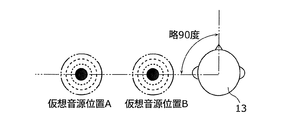
- FIG. 17 is a diagram illustrating the position of the virtual sound source in the direction of approximately 90 degrees of the listener according to the fourth embodiment.
- virtual sound source positions A and B indicate the positions of the virtual sound source in the direction of approximately 90 degrees of the listener 13.
- about 90 degrees is a direction prescribed
- the virtual sound source position A is a position farther from the listener 13 than the virtual sound source position B.
- the value of R when the ratio of ⁇ and ⁇ ( ⁇ / ⁇ ) is R, when the virtual sound source and the listener 13 are at the first distance, the value of R is set to the first value near 1. When the virtual sound source and the listener 13 are at a second distance shorter than the first distance, the value of R is set to a second value that is larger than the first value. In other words, when the position of the virtual sound source and the position of the listener 13 are far from each other, the value of R is set to the first value near 1, and when the position of the virtual sound source and the position of the listener 13 are close, the value of R The value is set to a second value (including infinity) that is greater than the first value.
- control is performed so that the ratio of ⁇ and ⁇ is approximately 1.
- control is performed so that ⁇ is sufficiently larger than ⁇ .
- the above “distant” is approximately 90 degrees away from the listener. If the direction in which the virtual speaker (virtual sound source) is placed is changed, that is, LVD and LVC are changed to a transfer function in which the virtual speaker (virtual sound source) is placed in a desired direction, the above "far” is desired. You can change the direction.
- the signal processing unit transmits sound from the virtual speaker placed on the side of the listener 13 to the first ear of the listener 13 close to the virtual speaker. Multiply the first transfer function, the second transfer function of the sound from the virtual sound source to the second ear opposite to the first ear, the first parameter ⁇ multiplied by the first transfer function, and the second transfer function.
- the filter processing using the second parameter ⁇ the first parameter ⁇ and the second parameter ⁇ are controlled. Thereby, the perspective of the sound source position can be controlled.
- the virtual speaker is set at a position of approximately 90 degrees of the listener.
- the process which paid its attention to the left ear was demonstrated, right and left may be reversed.
- the processing at the left ear and the processing at the right ear may be performed simultaneously to produce an ear feeling at both ears.
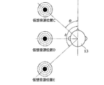
- FIG. 18 is a diagram illustrating the position of the virtual sound source on the listener side according to the fourth embodiment.
- virtual sound source positions C, D, and E indicate the positions of the virtual sound sources placed on the sides of the listener 13.
- the value of R when the ratio of ⁇ and ⁇ ( ⁇ / ⁇ ) is R, when the position of the virtual sound source is approximately 90 degrees with respect to the front direction of the listener 13, the value of R is set to 1. A larger value is set, and the value of R is made closer to 1 as the position of the virtual sound source deviates from approximately 90 degrees with respect to the front direction of the listener 13. In other words, when the virtual sound source is positioned substantially beside the listener 13, the value of R is set to a value greater than 1 (including infinity), and as the virtual sound source deviates from approximately beside the listener 13, Move the value closer to 1.
- a transfer function intended to place the virtual sound source at approximately ⁇ (0 ⁇ ⁇ ⁇ 90) degrees with respect to the signal of the sound.
- a transfer function process intended to place the virtual sound source at approximately 90 degrees is performed on the sound signal, and at the same time ⁇ and ⁇ Is set to a value larger than X.
- a transfer function process intended to place the virtual sound source at approximately ⁇ degrees is performed on the sound signal, and ⁇ and The ratio R with ⁇ is set to a value (Y) close to 1.
- X and Y may be the same.
- the audio playback device that localizes the sound to the listener's ear has been described.
- the technology in the present disclosure can also be realized as a gaming device that produces the fun of the game by the acoustic effect.
- the gaming device according to the present disclosure includes, for example, the audio playback device according to Embodiments 1 to 4.
- the signal processing unit 11 according to Embodiments 1 to 4 corresponds to an acoustic processing unit included in the gaming machine according to the present disclosure.
- the speaker array 12 according to Embodiments 1 to 4 corresponds to a sound output unit (speaker) included in the gaming machine according to the present disclosure.
- the player's sense of expectation of winning the game is presented to the player by means of an image display unit arranged in the gaming machine, thereby making the game fun. Directing.
- a gaming device may indicate to a player that a person or character that does not appear in the normal state of the game appears on the image display unit with an increased probability of winning the game, or that the color usage of the screen changes. Recognize. Thereby, the sense of expectation of winning the game can be enhanced, and as a result, the fun of the game can be increased.
- a game device has been developed that increases the fun of the game by changing the sound signal processing method according to the state of the game.
- Patent Document 3 discloses a technique for controlling acoustic signals output from a plurality of speakers in conjunction with the operation of a so-called slot machine variation display unit.
- the acoustic effect is varied by controlling the output level and phase of signals output from a plurality of speakers in accordance with the game situation (start, stop, winning type).
- the present disclosure has been made to solve the above-described conventional problems, and provides a gaming apparatus that can further increase the expectation that the player will win the game.
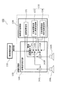
- FIG. 19 is a block diagram showing a configuration of the gaming apparatus 100 according to the fifth embodiment.
- the gaming apparatus 100 according to the fifth embodiment is a gaming apparatus that produces a sense of expectation that a player will win the game using a stereophonic technology.
- the gaming device 100 is a pachinko machine as shown in FIG. 20, a slot machine, other game machines, or the like.
- the gaming device 100 includes an expected value setting unit 110, an acoustic processing unit 120, and at least two speakers 150L and 150R.
- the acoustic processing unit 120 includes an acoustic signal storage unit 130 and an acoustic signal output unit 140.
- the expected value setting unit 110 sets an expected value for the player to win the game. Specifically, the expectation value setting unit 110 sets an expectation value that makes the player think that he or she will win the game. The detailed configuration and operation of the expected value setting unit 110 will be described later with reference to FIG. In the present embodiment, it is considered that the larger the set expected value is, the larger the expected value that the player will win the game is.
- the expected value setting unit 110 is a method that is used when a game device that has been widely used in the past is used to produce an expectation that makes a player feel like winning a game by using an image or lightning.
- the expected value may be set using a method for generating a state variable representing an increase in expectation.
- the acoustic processing unit 120 outputs an acoustic signal corresponding to the expected value set by the expected value setting unit 110. Specifically, when the expected value set by the expected value setting unit 110 is larger than a predetermined threshold, the acoustic processing unit 120 has stronger crosstalk cancellation performance than when the expected value is smaller than the threshold. The acoustic signal processed by the filter is output.
- the acoustic processing unit 120 outputs an acoustic signal accumulating unit 130 that accumulates an acoustic signal to be provided to the player during the game and an expected value set by the expected value setting unit 110. And an acoustic signal output unit 140 that changes the acoustic signal.
- the acoustic signal storage unit 130 is a memory for storing acoustic signals.
- the acoustic signal storage unit 130 stores a normal acoustic signal 131 and a sound effect signal 132.
- the normal acoustic signal 131 is an acoustic signal provided to the player regardless of the game state.
- the sound effect signal 132 is an acoustic signal provided in a single manner according to the state of the game. Note that the sound effect signal 132 includes a sound effect signal 133 without stereophonic sound processing and a sound effect signal 134 with stereophonic sound processing.
- 3D sound processing is processing in which sound can be heard at the player's ears.
- the sound effect signal with stereophonic sound processing 134 is an example of a first sound signal generated by signal processing with strong crosstalk cancellation performance.
- the sound effect signal 133 without stereophonic sound processing is an example of a second sound signal generated by signal processing with weak crosstalk cancellation performance. A method for generating these sound effect signals will be described later with reference to FIG.
- the acoustic signal output unit 140 reads the normal acoustic signal 131 and the sound effect signal 132 from the acoustic signal storage unit 130 and outputs them to the speakers 150L and 150R. As shown in FIG. 19, the acoustic signal output unit 140 includes a comparator 141, selectors 142L and 142R, and adders 143L and 143R.
- the comparator 141 compares the expected value set by the expected value setting unit 110 with a predetermined threshold value, and outputs the comparison result to the selectors 142L and 142R. In other words, the comparator 141 determines whether or not the expected value set by the expected value setting unit 110 is larger than a predetermined threshold value, and outputs the determination result to the selectors 142L and 142R.
- the selectors 142L and 142R receive the comparison result from the comparator 141 and select one of the sound effect signal 133 without stereophonic sound processing and the sound effect signal 134 with stereophonic sound processing. Specifically, the selectors 142L and 142R select the sound effect signal with stereophonic processing 134 when the expected value is larger than the threshold value. Further, the selectors 142L and 142R select the sound effect signal 133 without stereophonic processing when the expected value is smaller than the threshold value.
- the selector 142L outputs the selected sound effect signal to the adder 143L, and the selector 142R outputs the selected sound effect signal to the adder 143R.
- the adders 143L and 143R add the normal sound signal 131 and the sound effect signal selected by the selectors 142L and 142R, and output the result to the speakers 150L and 150R.
- the acoustic signal output unit 140 reads the sound signal 133 without stereophonic processing from the acoustic signal storage unit 130, It is added to the normal acoustic signal 131 and output.
- the acoustic signal output unit 140 reads the sound effect signal with stereophonic sound processing 134 from the acoustic signal storage unit 130 and performs normal sound processing. Add to signal 131 and output.
- Speakers 150L and 150R are an example of a sound output unit that outputs an acoustic signal output from the sound processing unit 120.
- the speakers 150L and 150R reproduce the acoustic signal output from the acoustic signal output unit 140 (an acoustic signal obtained by synthesizing the normal acoustic signal 131 and the sound effect signal 132).
- the gaming device 100 only needs to include at least two speakers, and may include three or more speakers.
- FIG. 21 is a block diagram illustrating an example of the configuration of the expected value setting unit 110 according to the fifth embodiment.
- the expected value setting unit 110 includes a winning lottery unit 111, a probability setting unit 112, a timer unit 113, and an expected value control unit 114, as shown in FIG.
- the winning lottery unit 111 determines whether the game is won or lost, that is, winning or not winning based on a predetermined probability. Specifically, the winning lottery unit 111 draws a winning or a non-winning according to the probability set by the probability setting unit 112. When the winning is won, the winning lottery unit 111 outputs a winning signal.
- the probability setting unit 112 sets the probability of winning the game. Specifically, the probability setting unit 112 sets a winning or non-winning probability for the game. For example, the probability setting unit 112 determines the probability of winning or not winning based on the duration information from the timer unit 113 and the progress of the game in the entire gaming device 100. For example, the probability setting unit 112 changes the probability of winning or not winning according to a player's proficiency level of the game, a game state change due to accidental action, and the like. The probability setting unit 112 outputs a signal indicating the set probability to the winning lottery unit 111 and the expected value control unit 114.
- the timer unit 113 measures the duration of the game. For example, the timer unit 113 measures the time elapsed from the start of the game by the player. The timer unit 113 outputs a signal indicating the measured duration to the probability setting unit 112 and the expected value control unit 114.
- the expected value control unit 114 sets an expected value for the player to win the game based on the probability set by the probability setting unit 112 and the duration measured by the timer unit 113. Specifically, the expectation value control unit 114 receives the signal output from the probability setting unit 112 and the signal output from the timer unit 113, and provides an expectation to be provided to the player. Control the expected value to win the game.
- the expected value control unit 114 increases the expected value when the duration time measured by the timer unit 113 reaches a predetermined time length, for example. For example, the expected value control unit 114 sets the expected value to a larger value when the duration is long than when the duration is short. That is, the expectation value control unit 114 may set the expectation value so that there is a positive correlation with the duration.
- the expected value control unit 114 varies the expected value according to the winning probability set by the probability setting unit 112. For example, the expected value control unit 114 sets the expected value to a larger value when the probability of winning is higher than when the probability of winning is low. That is, the expectation value control unit 114 may set the expectation value so that there is a positive correlation with the winning probability.
- the winning lottery unit 111 and the expected value control unit 114 perform winning or non-winning lottery and setting of the expected value based on the probability set by the probability setting unit 112. Thereby, since the probability of winning or not winning and the expected value are linked, it is possible to link the sense of expectation of the victory that the player receives from the sound signal and the possibility of the actual game winning.
- the expected value setting unit 110 is merely an example, and any method can be used as long as the possibility of winning the actual game and the expected value to be presented to the player are linked. May be.
- FIG. 22 is a diagram illustrating a signal flow until the acoustic signal according to Embodiment 5 reaches the player's ear. Specifically, FIG. 22 shows the flow of a signal that performs stereophonic processing on the input signal s and the processed signal is output from the speaker and reaches the left and right ears of the player.
- the input signal s is output from the left and right speakers 150L or 150R through the processing of the stereophonic sound processing filter TL or TR, respectively.
- the input signal s is an acoustic signal that is a source of the sound effect signal 133 without stereophonic sound processing and the sound effect signal 134 with stereophonic sound processing.
- the sound wave emitted from the left speaker 150L reaches the left ear of the player under the action of the spatial transfer function LD. Also, the sound wave output from the left speaker 150L reaches the player's right ear under the action of the spatial transfer function LC.
- the sound wave emitted from the right speaker 150R reaches the player's right ear under the action of the spatial transfer function RD. Also, the sound wave emitted from the right speaker 150R reaches the left ear of the player under the action of the spatial transfer function RC.
- the left ear signal le reaching the ear of the left ear and the right ear signal re reaching the ear of the right ear satisfy (Equation 3).
- the ear signal is obtained by multiplying the input signal s by a spatial acoustic transfer function and a stereophonic transfer function [TL, TR].
- [TL, TR] represents a matrix of 2 rows and 1 column (the same applies to the following description).
- a signal that reaches the ear on the opposite side of the speaker by the action of the spatial transfer function LC or RC is called a crosstalk signal.
- the sound effect signal with stereophonic sound processing 134 is, for example, a signal generated by performing a filtering process having the stereophonic transfer function [TL, TR] shown in (Expression 6) on the input signal s.
- the strength of the crosstalk cancellation performance increases as the ratio of the strength of the signal reaching each ear in the target characteristic of the ear signal increases. This is in line with the actual physical phenomenon that the voice whispered at the ear does not reach the opposite ear.
- the signal reaches the left ear and does not reach the right ear, but the left and right may be reversed.
- the sound effect signal 133 without stereophonic sound processing may be, for example, a signal subjected to filter processing in which the transfer function TL of stereophonic sound is set to 1 and TR is set to 0.
- FIG. 23 is a diagram illustrating another example of the signal flow until the acoustic signal according to Embodiment 5 reaches the player's ear.
- FIG. 23 differs from FIG. 22 in that a virtual speaker is set.
- the virtual speaker is an example of a virtual sound source placed on the side of the player.
- the virtual speaker is a virtual speaker that emits sound toward the ear from a substantially vertical direction in which the player is facing.
- the spatial transfer function LV is a transfer function of sound from the speaker to the ear when an actual speaker is placed at the position of the virtual speaker.
- Equation 8 is an equation showing the target characteristic of the ear signal reaching the player's ear in the signal flow shown in FIG. Specifically, in (Equation 8), the left ear is obtained by multiplying the input signal s by the space transfer function LV of the virtual speaker, that is, whether the input signal is emitted from the direction of approximately 90 degrees of the player.
- the target characteristic is such that the signal reaches the right ear and does not reach the right ear, that is, 0.
- Equation 8 shows, as shown in (Equation 9), the stereoacoustic transfer function [TL, TR] has a constant string of [LV, 0] in the inverse matrix of the determinant of the spatial acoustic transfer function. It will be multiplied.
- the sound effect signal with stereophonic sound processing 134 may be, for example, a signal generated by performing a filtering process having the stereophonic transfer function [TL, TR] shown in (Equation 9) on the input signal s. .
- the virtual speaker is set at a position of approximately 90 degrees of the player, but may not necessarily be approximately 90 degrees.
- the virtual speaker may be located on the side of the player.
- the signal reaches the left ear and does not reach the right ear, the left and right may be reversed.
- the gaming device 100 has an expected value setting unit 110 that sets an expected value for the player to win the game, and an acoustic that corresponds to the expected value set by the expected value setting unit 110.
- the acoustic processing unit 120 that outputs a signal, and at least two speakers 150L and 150R that output the acoustic signal output from the acoustic processing unit 120.
- the acoustic processing unit 120 is set by the expected value setting unit 110.
- the expected value is larger than a predetermined threshold, an acoustic signal processed by a filter having a stronger crosstalk cancellation performance is output than when the expected value is smaller than the threshold.
- the player's expectation of winning the game can be produced by a whisper or sound effect that can be heard at the player's ears, the player's expectation of winning the game can be further enhanced.
- the sound processing unit 120 is more effective than the sound effect signal with stereophonic sound processing 134 and the sound effect signal with stereophonic sound processing 134 processed by a filter having strong crosstalk cancellation performance.
- the stereophonic processing A sound signal output unit 140 that selects and outputs the attached sound effect signal 134 and selects and outputs the sound effect signal 133 without stereophonic sound processing when the expected value set by the expected value setting unit 110 is smaller than the threshold value.
- one of the sound effect signal without stereophonic sound processing 133 and the sound effect signal with stereophonic sound processing 134 may be selected based on the comparison result between the expected value and the threshold value, the player can play the game with simple processing. The expectation to win can be further increased. That is, the sound effect signal 133 without stereophonic sound processing and the sound effect signal 134 with stereophonic sound processing may be generated and stored in advance.
- the expected value setting unit 110 includes a probability setting unit 112 that sets a probability of winning the game, a timer unit 113 that measures the duration of the game, and a probability setting unit 112. Is provided with an expected value control unit 114 that sets an expected value based on the probability set by the above and the duration measured by the timer unit 113.
- the expected value is set based on the probability of winning the game and the duration, so that, for example, the intention that the gaming device 100 tries to win the player and the expectation that the player will win the game Can be linked.
- the sound processing unit 120 prepares the sound effect signal 133 without stereophonic sound processing and the sound effect signal 134 with stereophonic sound processing in advance, and which one to select according to the expected value.
- the sound effect signal may be changed by switching stereophonic sound processing software that operates in real time.
- the acoustic processing unit 120 performs stereophonic sound processing on the sound effect signal when the expected value is greater than the threshold value, and outputs the sound effect signal. If the expected value is smaller than the threshold value, the sound processing unit 120 performs the stereo sound processing on the sound effect signal. May be output without executing.
- the acoustic signal storage part 130 has memorize
- the acoustic signal storage unit 130 may store a plurality of signals having different degrees of stereophonic effect.
- the acoustic signal output unit 140 may switch a plurality of signals according to the magnitude of the expected value set by the expected value setting unit 110.
- the acoustic signal storage unit 130 stores three sound effect signals including a first sound effect signal, a second sound effect signal, and a third sound effect signal.
- the first sound effect signal has the weakest stereo sound effect
- the third sound effect signal has the strongest stereo sound effect.
- the acoustic signal output unit 140 reads and outputs the first sound effect signal when the expected value is smaller than the first threshold value.
- the acoustic signal output unit 140 reads and outputs the second sound effect signal when the expected value is larger than the first threshold value and smaller than the second threshold value.
- the acoustic signal output unit 140 reads and outputs the third sound effect signal when the expected value is larger than the second threshold value. Note that the first threshold value is smaller than the second threshold value.
- the sound effect signal having different stereophonic effects is output according to the magnitude of the expected value, the sound effect signal corresponding to the player's expectation can be output.
- the expectation may be produced by an acoustic signal for a player who is expected to win among a plurality of players via the gaming apparatus 100.
- each of the normal sound signals 131 (for example, BGM that is always output) is added with a sound effect (sound that is emitted only once). Explanation of volume was omitted.
- the volume of the normal sound signal or the sound effect signal may be changed based on the expected value.
- FIG. 24 is a block diagram showing another example of the configuration of the gaming device according to the fifth embodiment. Specifically, FIG. 24 shows a configuration example of the gaming apparatus 200 capable of controlling the volume when adding sound effects.
- acoustic processing unit 220 is provided instead of the acoustic processing unit 120.
- the acoustic processing unit 220 is different from the acoustic processing unit 120 in that an acoustic signal output unit 240 is provided instead of the acoustic signal output unit 140.
- the acoustic signal output unit 240 is different from the acoustic signal output unit 140 in that it further includes volume adjusting units 244L and 244R.
- the volume adjusters 244L and 244R receive the comparison result from the comparator 141 and adjust the volume of the normal acoustic signal 131. Specifically, the volume adjusting units 244L and 244R, when the selectors 142L and 142R have selected the sound effect signal with stereophonic processing 134, than when the sound effect signal 133 without stereophonic processing has been selected, The volume of the normal acoustic signal 131 is reduced. Thereby, the effect of the stereophonic sound processing (particularly the effect of localization of the sound image at the ear) can be emphasized and provided to the player.
- the volume of the sound effect signal 132 may be adjusted instead of the volume of the normal sound signal 131. That is, when the selectors 142L and 142R have selected the sound effect signal with stereophonic sound processing 134, the sound volume adjusting unit has the sound effect with stereophonic sound processing more effective than when the sound effect signal 133 without stereophonic sound processing is selected. The volume of the signal 134 may be increased.
- the present invention is not limited thereto.
- a process for achieving a feeling of sound wrapping in a space surrounding the player may be used.
- FIG. 25 is a block diagram showing another example of the configuration of the gaming device according to the fifth embodiment. Specifically, FIG. 25 illustrates a configuration example of a gaming apparatus 300 that can selectively output a reverberation signal to be artificially applied based on an expected value.
- the acoustic processing unit 320 gives the acoustic signal a larger reverberation component than when the expected value is smaller than the threshold value, and outputs the acoustic signal.
- the acoustic processing unit 320 is different from the acoustic processing unit 120 in that an acoustic signal storage unit 330 is provided instead of the acoustic signal storage unit 130. More specifically, the acoustic signal storage unit 330 is different in that it stores a reverberation signal 332 instead of the sound effect signal 132.
- the reverberation signal 332 is a signal indicating an artificially generated reverberation component.
- the reverberation signal 332 includes a small reverberation signal 333 and a large reverberation signal 334.
- the small reverberation signal 333 is a signal whose reverberation signal level and reverberation length are smaller than the large reverberation signal 334.
- the selectors 142L and 142R receive the comparison result from the comparator 141 and select one of the small reverberation signal 333 and the large reverberation signal 334. Specifically, the selectors 142L and 142R select the large reverberation signal 334 when the expected value is larger than the threshold value, and select the small reverberant signal 333 when the expected value is smaller than the threshold value.
- the level of the reverberation signal or the length of the reverberation can be increased artificially than when the expected value is small.
- the expectation that the player expects from the game can be produced by the feeling of sound wrapping in the space surrounding the player.
- the acoustic signal storage unit 330 stores two types of reverberation signals, but may store only one type of reverberation signal.
- the selectors 142L and 142R may select the reverberation signal when the expected value is larger than the threshold value, and may not select the reverberant signal when the expected value is smaller than the threshold value.
- the gaming apparatus 300 is based on the expected value setting unit 110 that sets an expected value for the player to win the game, and the expected value set by the expected value setting unit 110.
- a sound processing unit 320 that outputs the sound signal, and at least two speakers 150L and 150R that output the sound signal output from the sound processing unit 320.
- the sound processing unit 320 is controlled by the expected value setting unit 110.
- the set expected value is larger than a predetermined threshold value
- a reverberation component larger than when the expected value is smaller than the threshold value is given to the normal sound signal 131 and output.
- FIG. 26 is a block diagram showing a configuration of the gaming apparatus 400 according to the sixth embodiment.
- a gaming device 400 according to the sixth embodiment is a gaming device that produces a sense of expectation that a player will win the game by a technique that adjusts the strength of the sense of ear reproduction.
- the gaming device 400 is, for example, a pachinko machine as shown in FIG. 20 as in the fifth embodiment.
- the sound processing unit 420 outputs a sound effect signal having a stronger ear feeling.
- the acoustic processing unit 420 is different from the acoustic processing unit 120 in that an acoustic signal storage unit 430 is provided instead of the acoustic signal storage unit 130. More specifically, the acoustic signal storage unit 430 is different in that the sound effect signal 432 is stored instead of the sound effect signal 132.
- the sound effect signal 432 is an acoustic signal provided in a single manner according to the game state.
- the sound effect signal 432 includes a sound effect signal 433 with a weak ear feeling and a sound effect signal 434 with a strong ear feeling.
- the sound effect signal 433 with a weak ear feeling is an example of a second acoustic signal generated by signal processing with a weak crosstalk cancellation performance. For example, an acoustic signal that can be heard by both player's ears with substantially the same size. It is.
- the sound effect signal 434 having a strong ear feeling is an example of a first acoustic signal generated by signal processing having a strong crosstalk cancellation performance. For example, the sound signal 434 is heard by one player's ear and hardly heard by the other ear. Such an acoustic signal.
- the selectors 142L and 142R receive the comparison result from the comparator 141 and select one of the sound effect signal 433 having a weak ear feeling and the sound effect signal 434 having a strong ear feeling. Specifically, the selectors 142L and 142R select the sound effect signal 434 having a strong ear feeling when the expected value is larger than the threshold value, and select the sound effect signal 433 having a weak ear feeling when the expected value is smaller than the threshold value. select.
- the expected value set by the expected value setting unit 110 is large, it is possible to output the sound effect signal 434 having a stronger sense of ear than when the expected value is small.
- the expectation that the player expects from the game can be produced by the feeling of sound wrapping in the space surrounding the player.
- the parameters ⁇ and ⁇ shown in (Equation 1) and (Equation 2) are determined based on the expected value set by the expected value setting unit 110 for the player to win the game. Specifically, ⁇ and ⁇ are determined so that the difference between ⁇ and ⁇ increases as the expected value increases. For example, the larger the expected value, the larger the difference between ⁇ and ⁇ ( ⁇ >> ⁇ ), or when the expected value is not so large, ⁇ and ⁇ are set to the same value ( ⁇ ⁇ ⁇ ) can increase the fun of exciting games.
- a sound effect signal 433 with a weak ear feeling and a sound effect signal 434 with a strong ear feeling are generated. Specifically, a sound effect signal 433 with a weak ear feeling is generated when ⁇ , and a sound effect signal 434 with a strong ear feeling is generated when ⁇ >> ⁇ .
- the sound processing unit 420 is a sound that reaches the first ear of the player close to the virtual speaker from the virtual speaker placed on the side of the player.
- the first parameter and the second parameter are determined according to the expected value set by the expected value setting unit 110, so that processing is performed with a filter having strong crosstalk cancellation performance. Output the sound signal.
- the parameter is determined according to the expected value, for example, the level of expectation that the player can win the game can be produced by a whisper or sound effect that can be heard at the player's ear.
- the first parameter and the second parameter are compared with the case where the expected value is smaller than the threshold.
- the first parameter and the second parameter are determined so that the difference becomes large.
- the larger the expected value the larger the sound that can be heard by one ear and the smaller the sound that can be heard by the other ear.
- the level of expectation that a player can win the game It can be produced by a whisper or sound effect that can be heard.
- the virtual speaker is set at a position of approximately 90 degrees of the player, but it does not necessarily have to be approximately 90 degrees.
- the virtual speaker may be located on the side of the player.
- right and left may be reversed.
- the processing at the left ear and the processing at the right ear may be performed simultaneously to produce an ear feeling at both ears.
- the acoustic processing unit 420 prepares in advance a sound effect signal 433 having a weak ear feeling and a sound effect signal 434 having a strong ear feeling, in which the ear feeling is processed in advance as described above, although it is configured for switching which one to select according to the expected value, it is not limited to this.
- the transfer function [TL, TR] of the stereophonic sound may be adjusted according to the expected value, and the filter processing may be performed in real time.
- FIG. 27 is a block diagram showing a configuration of a gaming apparatus 500 according to a modification of the sixth embodiment.
- the gaming apparatus 500 is different from the gaming apparatus 100 shown in FIG. 19 in that an acoustic processing unit 520 is provided instead of the acoustic processing unit 120.
- the acoustic processing unit 520 outputs an acoustic signal corresponding to the expected value set by the expected value setting unit 110. For example, in the filter processing using the transfer function VLD, the transfer function VLC, the parameter ⁇ , and the parameter ⁇ , the acoustic processing unit 520 determines the parameters ⁇ and ⁇ according to the expected values set by the expected value setting unit 110. Is determined to generate and output an acoustic signal processed by a filter having strong crosstalk cancellation performance.
- the acoustic processing unit 520 includes an acoustic signal storage unit 530 and an acoustic signal output unit 540.
- the acoustic signal storage unit 530 is a memory for storing acoustic signals.
- the acoustic signal storage unit 530 stores a normal acoustic signal 131 and a sound effect signal 532.
- the normal acoustic signal 131 is the same as that of the fifth embodiment, and the sound effect signal 532 is an acoustic signal provided in a single manner according to the game state.
- the acoustic signal output unit 540 generates and outputs a sound effect signal having a weak ear reproduction feeling or a sound effect signal having a strong ear reproduction feeling in accordance with the expected value set by the expected value setting unit 110.
- the acoustic signal output unit 540 includes a parameter determination unit 541 and a filter processing unit 542.
- the parameter determination unit 541 determines the parameters ⁇ and ⁇ based on the expected value set by the expected value setting unit 110. Specifically, the parameter determination unit 541 has a larger difference between the parameter ⁇ and the parameter ⁇ when the expected value set by the expected value setting unit 110 is larger than the threshold than when the expected value is smaller than the threshold. Thus, the parameters ⁇ and ⁇ are determined. For example, the parameter determination unit 541 determines the parameters ⁇ and ⁇ so that the difference between the parameter ⁇ and the parameter ⁇ increases as the expected value increases.
- the parameter determination unit 541 determines ⁇ and ⁇ as described with reference to FIG. 16 in conjunction with the expected value that is set by the expected value setting unit 110 and the player wins the game. Specifically, the parameter determination unit 541 determines ⁇ and ⁇ so that the difference between ⁇ and ⁇ increases as the expected value increases. For example, the parameter determining unit 541 makes ⁇ and ⁇ larger as the expected value is larger ( ⁇ >> ⁇ ), or when the expected value is not so large, ⁇ and ⁇ are set the same. By making the value small ( ⁇ ), it is possible to increase the fun of exciting games.
- the filter processing unit 542 performs filter processing using the transfer function LVD, the transfer function LVC, the parameter ⁇ , and the parameter ⁇ on the sound effect signal. In other words, the filter processing unit 542 performs filter processing for adjusting the ear reproduction feeling on the sound effect signal. For example, the filter processing unit 542 processes the sound effect signal 532 using the stereophonic transfer function [TL, TR] represented by (Expression 2).
- the parameter is determined according to the expected value.
- the player can hear the level of expectation of winning the game at the player's ear. It can be produced by voice or sound effects.
- the sound processing unit 520 is configured so that the first ear of the player close to the virtual speaker from the virtual speaker placed on the side of the player.
- the first parameter and the second parameter are determined according to the expected value set by the expected value setting unit 110, so that the filter having strong crosstalk cancellation performance
- the acoustic signal processed in is output.
- the parameter is determined according to the expected value, for example, the level of expectation that the player can win the game can be produced by a whisper or sound effect that can be heard at the player's ear.
- the acoustic processing unit 520 has the first parameter when the expected value set by the expected value setting unit 110 is larger than the threshold value than when the expected value is smaller than the threshold value.
- the first parameter and the second parameter are determined so that the difference between the first parameter and the second parameter becomes large.
- the larger the expected value the larger the sound that can be heard by one ear and the smaller the sound that can be heard by the other ear.
- the level of expectation that a player can win the game It can be produced by a whisper or sound effect that can be heard.
- Embodiments 1 to 6 have been described as examples of the technology disclosed in the present application. However, the technology in the present disclosure is not limited to this, and can also be applied to an embodiment in which changes, replacements, additions, omissions, and the like are appropriately performed. Also, it is possible to combine the components described in the first to sixth embodiments to form a new embodiment.
- the comprehensive or specific aspect of the audio playback device and game device described in each of the above embodiments is realized by a system, method, integrated circuit, computer program, or computer-readable recording medium such as a CD-ROM. It may be realized by any combination of a system, a method, an integrated circuit, a computer program, and a recording medium.
- the technology in the present disclosure includes a signal processing device that is a device obtained by removing a speaker array (speaker element) from the audio reproduction device described in the above embodiments.
- each component (expected value setting unit 110, acoustic processing unit 120, acoustic signal storage unit 130, and acoustic signal output unit 140) constituting the gaming device 100 according to the fifth embodiment of the present disclosure is a CPU ( It may be realized by software such as a program executed on a computer equipped with a central processing unit (RAM), a RAM (Random Access Memory), a ROM, a communication interface, an I / O port, a hard disk, a display, etc., or a hardware such as an electronic circuit It may be realized by hardware. The same applies to each component constituting the gaming devices 200 to 500 according to other embodiments.
- the gaming device produces an expectation that the player will win the game by an acoustic signal, so that the fun of the game can be increased in a so-called pachinko machine or slot machine, and widely used in gaming devices. can do.
- each component may be configured by dedicated hardware or may be realized by executing a software program suitable for each component.
- Each component may be realized by a program execution unit such as a CPU or a processor reading and executing a software program recorded on a recording medium such as a hard disk or a semiconductor memory.
- the audio playback device can be widely applied to game machines, digital signage devices, and the like.
Landscapes
- Engineering & Computer Science (AREA)
- Physics & Mathematics (AREA)
- Acoustics & Sound (AREA)
- Signal Processing (AREA)
- Multimedia (AREA)
- Health & Medical Sciences (AREA)
- General Health & Medical Sciences (AREA)
- Otolaryngology (AREA)
- Stereophonic System (AREA)
- Circuit For Audible Band Transducer (AREA)
Abstract
オーディオ再生装置(10)は、オーディオ信号をN個(Nは3以上の整数)のチャネル信号に変換する信号処理部(11)と、N個のチャネル信号をそれぞれ再生音として出力するN個のスピーカ素子からなるスピーカアレー(12)とを備え、信号処理部(11)は、スピーカアレー(12)から出力される再生音をリスナー(13)の一方の耳元の位置で共振させるビームフォーム処理を行うビームフォーム部(20)と、スピーカアレー(12)から出力される再生音がリスナー(13)の他方の耳元の位置に到達することを抑制するキャンセル処理を行うキャンセル部(21)とを有する。
Description
本開示は、音をリスナーの耳元に定位させるオーディオ再生装置、及び、音響効果によって遊技の楽しさを演出する遊技装置に関する。
近年、2つのスピーカを用いて仮想的に立体的な音場をリスナーに提供する技術が開発されている。例えば、バイノーラル録音したオーディオ信号を2つのスピーカから出音(再生)する際に生じるクロストークをキャンセルする方法(例えば、特許文献1参照)が広く知られている。
一方、スピーカアレーを用いることによって、仮想的な音場をリスナーに提供する技術も知られている(例えば、特許文献2参照)。
AES 127th Convention, New York NY, USA, 2009 October 9-12 Physical and Perceptual Properties of Focused Sources in Wave Field Synthesis
2つのスピーカから出音する際に生じるクロストークをキャンセルする技術では、スピーカの位置とリスナーの位置との関係が伝達特性による制約を受ける。このため、スピーカの位置とリスナーの位置とが一定の関係を維持することができない場合、所望の効果が得られない。つまり、いわゆるスイートスポットが狭いことが課題である。
一方、スピーカアレーを用いて仮想的に音場を生成する技術では、スイートスポットを広くすることができる。しかしながら、スピーカアレーから出力される平面波をリスナーの位置で交差させる必要がある。このため、スピーカアレーを交差させて配置する必要があり、スピーカの配置に制約が生じることが課題である。
そこで、本開示は、バイノーラル録音を用いずに所定の音をリスナーの耳元に定位させることができ、かつ、スピーカ(スピーカ素子)の配置の制約を緩和したオーディオ再生装置を提供する。
上記の課題を解決するために、本開示の一態様に係るオーディオ再生装置は、音をリスナーの耳元に定位させるオーディオ再生装置であって、オーディオ信号をN個(Nは3以上の整数)のチャネル信号に変換する信号処理部と、前記N個のチャネル信号をそれぞれ再生音として出力する少なくともN個のスピーカ素子からなるスピーカアレーとを備え、前記信号処理部は、前記スピーカアレーから出力される再生音を前記リスナーの一方の耳元の位置で共振させるビームフォーム処理を行うビームフォーム部と、前記スピーカアレーから出力される再生音が前記リスナーの他方の耳元の位置に到達することを抑制するキャンセル処理を行うキャンセル部とを有し、前記N個のチャネル信号は、前記オーディオ信号が前記ビームフォーム処理され、かつ、前記キャンセル処理されることによって得られる信号である。
これにより、直線のスピーカアレーを用いて、リスナーの耳元に音(音像)を定位させることが可能となる。
また、前記Nは、偶数であり、前記キャンセル部は、前記オーディオ信号が前記ビームフォーム処理されることによって生成されるN個の信号に対して、N/2個のペアごとに前記キャンセル処理であるクロストークキャンセル処理を行い、前記N個のチャネル信号を生成してもよい。
これにより、クロストークキャンセル処理に用いるフィルタ(の定数)は、2個のスピーカ素子の組とリスナーとの幾何学的な位置関係だけから求められるので、クロストークキャンセル処理に用いるフィルタを簡単に定義することができる。
また、前記キャンセル部は、前記ビームフォーム部に入力される入力信号が前記スピーカアレーから再生音として出力されてリスナーの耳元にいたるまでの伝達関数に基づいて、前記キャンセル処理であるクロストークキャンセル処理を前記オーディオ信号に対して行い、前記ビームフォーム部は、前記クロストークキャンセル処理された前記オーディオ信号に対して前記ビームフォーム処理を行い、前記N個のチャネル信号を生成してもよい。
これにより、クロストークキャンセル処理がN個に分けられる前のオーディオ信号に行われるので、演算量が少なくて済む。
また、前記ビームフォーム部は、前記オーディオ信号を所定の周波数帯域ごとに分割した信号である帯域信号を生成する帯域分割フィルタと、生成された帯域信号を前記N個のスピーカ素子のそれぞれに対応するチャネルに分配する分配部と、分配された帯域信号に対して、当該帯域信号の分配先の前記スピーカ素子の位置と、当該帯域信号の周波数帯域とに応じてフィルタ処理を施し、フィルタ済み信号として出力する位置・帯域別フィルタと、同一のチャネルに属する複数の前記フィルタ済み信号を帯域合成する帯域合成フィルタとを有してもよい。
これにより、ビームフォーム処理を周波数帯域ごとに制御できるので高音質化できる。
また、前記帯域分割フィルタは、前記オーディオ信号を高域の帯域信号及び低域の帯域信号に分割し、前記位置・帯域別フィルタは、分配されたN個の前記高域の帯域信号のうちH個(HはN以下の正の整数)の前記高域の帯域信号に対して前記フィルタ処理を施した場合、分配されたN個の前記低域の帯域信号のうちL個(LはHよりも小さい正の整数)の前記低域の帯域信号に対して前記フィルタ処理を施してもよい。
これにより、低周波数帯域の音と、高周波数帯域の音とのバランスをとることができる。
また、前記位置・帯域別フィルタは、特定のチャネルの前記フィルタ済み信号の振幅が、前記特定のチャネルの両隣のチャネルの前記フィルタ済み信号の振幅よりも大きくなるように、前記分配された帯域信号に対して前記フィルタ処理を施してもよい。
これにより、スピーカ素子のチャネル間の音圧をイコライズすることができる。
また、前記信号処理部は、さらに、前記キャンセル処理される前の前記オーディオ信号の低域部分の倍音成分を当該オーディオ信号に加算する低音強調部を有してもよい。
これにより、クロストークキャンセル処理によって損なわれる低音を、ミッシングファンダメンタル現象を活用して補うことができる。
また、本開示の一態様に係るオーディオ再生装置は、音をリスナーの耳元に定位させるオーディオ再生装置であって、オーディオ信号を左チャネル信号及び右チャネル信号に変換する信号処理部と、前記左チャネル信号を再生音として出力する左スピーカ素子と、前記右チャネル信号を再生音として出力する右スピーカ素子とを備え、前記信号処理部は、前記オーディオ信号の低域部分の倍音成分を当該オーディオ信号に加算する低音強調部と、前記右スピーカ素子から出力される再生音が前記リスナーの左耳の位置に到達することを抑制し、前記左スピーカ素子から出力される再生音が前記リスナーの右耳の位置に到達することを抑制するキャンセル処理を、前記倍音成分が加算された前記オーディオ信号に対して行い、前記左チャネル信号及び前記右チャネル信号を生成するキャンセル部とを有する。
これにより、スピーカ素子が2つの場合に、クロストークキャンセル処理によって損なわれる低音を、ミッシングファンダメンタル現象を活用して補うことができる。
また、本開示の一態様に係るオーディオ再生装置は、オーディオ信号を左チャネル信号及び右チャネル信号に変換する信号処理部と、前記左チャネル信号を再生音として出力する左スピーカ素子と、前記右チャネル信号を再生音として出力する右スピーカ素子とを備え、前記信号処理部は、前記オーディオ信号の音を所定の位置に定位させ、前記左スピーカ素子及び前記右スピーカ素子に向き合うリスナーの一方の耳元の位置で音が強調されて知覚されるように設計されたフィルタを有し、当該フィルタによって処理された前記オーディオ信号を前記左チャネル信号及び前記右チャネル信号に変換し、前記所定の位置は、上面視した場合に、前記リスナーの位置と、前記左スピーカ素子及び前記右スピーカ素子のうち前記一方の耳元の位置側のスピーカ素子とを結ぶ直線で分けられた2つの領域のうち、前記一方の耳元の位置側の領域に位置してもよい。
これにより、2つのスピーカ素子を用いて、リスナーの耳元に音(音像)を定位させることができる。
また、前記信号処理部は、さらに、前記オーディオ信号の音が前記リスナーの他方の耳元で知覚されることを抑制するキャンセル処理を前記オーディオ信号に対して行い、前記左チャネル信号及び前記右チャネル信号を生成するクロストークキャンセル部を有し上面視した場合に、前記所定の位置と前記リスナーの位置とを結ぶ直線は、前記左スピーカ素子と前記右スピーカ素子とを結ぶ直線と略平行であってもよい。
これにより、2つのスピーカ素子を用い、かつ、簡易なフィルタ構成でリスナーの耳元に音を定位させることができる。
また、本開示の一態様に係るオーディオ再生装置は、音をリスナーの耳元に定位させるオーディオ再生装置であって、オーディオ信号を左チャネル信号及び右チャネル信号に変換する信号処理部と、前記左チャネル信号を再生音として出力する左スピーカ素子と、前記右チャネル信号を再生音として出力する右スピーカ素子とを備え、前記信号処理部は、前記リスナーの側方に置かれた仮想音源から、当該仮想音源に近い前記リスナーの第1の耳に至る音の第1伝達関数と、前記仮想音源から、前記第1の耳の反対側の第2の耳に至る音の第2伝達関数と、前記第1伝達関数に乗ずる第1パラメータと、前記第2伝達関数に乗ずる第2パラメータとを用いたフィルタ処理を行ってもよい。
これにより、2つのスピーカ素子を用い、かつ、簡易なフィルタ構成で、移動する仮想音源を高い臨場感で再現させることができる。
また、前記信号処理部は、前記第1パラメータがα、前記第2パラメータがβ、前記第1パラメータと前記第2パラメータとの比(α/β)がRである場合において、(i)前記仮想音源と前記リスナーとの距離が第1の距離であるとき、前記Rの値を1近傍の第1の値に設定し、(ii)前記仮想音源と前記リスナーとが前記第1の距離より近い第2の距離であるとき、前記Rの値を前記第1の値より大きい第2の値に設定してもよい。
これにより、2つのスピーカ素子を用い、かつ、簡易なフィルタ構成で、仮想音源の位置とリスナーの位置との遠近感を再現させることができる。
また、前記信号処理部は、前記第1パラメータがα、前記第2パラメータがβ、前記第1パラメータと前記第2パラメータとの比(α/β)がRである場合において、(i)前記仮想音源の位置が前記リスナーの正面方向に対して略90度のとき、前記Rの値を1より大きい値に設定し、(ii)前記仮想音源の位置が前記リスナーの正面方向に対して略90度から外れる程、前記Rの値を1に近づけてもよい。
これにより、2つのスピーカ素子を用い、かつ、簡易なフィルタ構成で、仮想音源がリスナーの側方を移動する音響効果を演出することができる。
また、本開示の一態様に係る遊技装置は、遊技者が遊技に勝利する期待値を設定する期待値設定部と、前記期待値設定部によって設定された期待値に応じた音響信号を出力する音響処理部と、前記音響処理部から出力された音響信号を出音する少なくとも2個の出音部とを備え、前記音響処理部は、前記期待値設定部によって設定された期待値が、予め定められた閾値より大きい場合、当該期待値が前記閾値より小さい場合よりも、クロストークキャンセル性能の強いフィルタで処理された音響信号を出力する。
これにより、期待値が大きい場合に、期待値が小さい場合よりもクロストークキャンセル性能の強いフィルタで処理された音響信号を出音するので、遊技者は、耳元で聞こえる音によって遊技に勝利する期待感を、より高く感じることができる。例えば、遊技者が遊技に勝利する期待感を、遊技者の耳元で聞こえる囁き声又は効果音によって演出することができるので、遊技者が遊技に勝利する期待感を、より高めることができる。
また、例えば、本開示の一態様に係る遊技装置では、前記音響処理部は、前記遊技者の側方に置かれた仮想音源から、当該仮想音源に近い前記遊技者の第1の耳に至る音の第1伝達関数と、前記仮想音源から、前記第1の耳の反対側の第2の耳に至る音の第2伝達関数と、前記第1伝達関数に乗ずる第1パラメータと、前記第2伝達関数に乗ずる第2パラメータとを用いたフィルタ処理において、前記第1パラメータと前記第2パラメータとを、前記期待値設定部によって設定された期待値に応じて決定することで、クロストークキャンセル性能の強いフィルタで処理された音響信号を出力してもよい。
これにより、期待値に応じてパラメータを決定するので、例えば、遊技者が遊技に勝利する期待感の大小を、遊技者の耳元で聞こえる囁き声又は効果音の大小によって演出することができる。
また、例えば、本開示の一態様に係る遊技装置では、前記音響処理部は、前記期待値設定部によって設定された期待値が前記閾値より大きい場合に、前記期待値が前記閾値より小さい場合よりも、前記第1パラメータと前記第2パラメータとの差が大きくなるように、前記第1パラメータ及び前記第2パラメータを決定してもよい。
これにより、期待値が大きい程、一方の耳に聞こえる音が大きくなり、他方の耳に聞こえる音が小さくなるので、例えば、遊技者が遊技に勝利する期待感の大小を、遊技者の耳元で聞こえる囁き声又は効果音によって演出することができる。
また、例えば、本開示の一態様に係る遊技装置では、前記音響処理部は、クロストークキャンセル性能の強いフィルタで処理された第1音響信号と、前記第1音響信号よりもクロストークキャンセル性能の弱いフィルタで処理された第2音響信号とを格納する蓄積部と、前記期待値設定部によって設定された期待値が前記閾値より大きい場合に前記第1音響信号を選択して出力し、前記期待値設定部によって設定された期待値が前記閾値より小さい場合に前記第2音響信号を選択して出力する選択部とを備えてもよい。
これにより、簡易な処理で遊技者が遊技に勝利する期待感をより高めることができる。
また、例えば、本開示の一態様に係る遊技装置は、遊技者が遊技に勝利する期待値を設定する期待値設定部と、前記期待値設定部によって設定された期待値に応じた音響信号を出力する音響処理部と、前記音響処理部から出力された音響信号を出音する少なくとも2個の出音部とを備え、前記音響処理部は、前記期待値設定部によって設定された期待値が、予め定められた閾値より大きい場合、当該期待値が前記閾値より小さい場合よりも大きい残響成分を前記音響信号に付与して出力してもよい。
これにより、期待値が大きい場合に期待値が小さい場合よりも大きい残響成分を音響信号に付与するので、遊技者が遊技に勝利する期待感を、遊技者を取り囲む空間における音の包まれ感によって演出することができる。
また、例えば、本開示の一態様に係る遊技装置では、前記期待値設定部は、前記遊技に勝利する確率を設定する確率設定部と、前記遊技の継続時間を計測するタイマー部と、前記確率設定部によって設定された確率と、前記タイマー部によって計測された継続時間とに基づいて、前記期待値を設定する期待値制御部とを備えてもよい。
これにより、遊技装置が遊技者に勝利させようとする意図と、遊技者が遊技に勝利する期待感とを連動させることができる。
本開示のオーディオ再生装置によれば、バイノーラル録音を用いずに所定の音をリスナーの耳元に定位させることができ、かつ、スピーカアレーの配置の制約が緩和される。
(本開示の基礎となった知見)
背景技術で説明したように、2つのスピーカを用いて仮想的に立体的な音場をリスナーに提供する技術が開発されている。例えば、バイノーラル録音したオーディオ信号を2つのスピーカから出音する際にクロストークキャンセルする方法が広く知られている。
背景技術で説明したように、2つのスピーカを用いて仮想的に立体的な音場をリスナーに提供する技術が開発されている。例えば、バイノーラル録音したオーディオ信号を2つのスピーカから出音する際にクロストークキャンセルする方法が広く知られている。
バイノーラル録音とは、図1に示されるような、いわゆるダミーヘッドの両耳に仕込んだマイクロホンによって音声を収音することで、人間の両耳に到達する音波をそのまま録音することである。リスナーは、このように録音されたオーディオ信号の再生音を、ヘッドホンを用いて受聴すれば、録音した際の空間音響を知覚することができる。
ただし、スピーカを用いて聴く場合は、右耳元で収音した音が左耳にも到達し、また逆に左耳元で収音した音が右耳にも到達するので、バイノーラル録音の効果が損なわれる。これを解決する方法として、クロストークキャンセル処理が従来から知られている。
図2は、一般的なクロストークキャンセル処理を説明するための図である。図2では、左ch用スピーカSP-Lからリスナーの左耳元にいたる音の伝達関数はhFL、左ch用スピーカSP-Lからリスナーの右耳元にいたる音の伝達関数はhCLと表現される。また、右ch用スピーカSP-Rからリスナーの右耳元にいたる音の伝達関数はhFR、右ch用スピーカSP-Rからリスナーの左耳元にいたる音の伝達関数はhCRと表現される。この場合、伝達関数の行列Mは、図2に示される行列となる。
また、図2では、ダミーヘッドの左耳元で録音された信号はXL、ダミーヘッドの右耳元で録音された信号はXRと表現され、リスナーの左耳元に到達する信号はZL、リスナーの右耳元に到達する信号はZRと表現される。
ここで、入力信号[XL,XR]に行列Mの逆行列M-1が乗算された信号[YL,YR]の再生音が左ch用スピーカSP-L及び右ch用スピーカSP-Rから出音されると、リスナーの耳元には、信号[YL,YR]に行列Mが乗算された信号が到達する。
このため、入力信号[XL,XR]が、リスナーの左右の耳元に到達する信号[ZL,ZR]となる。すなわち、クロストーク成分(左ch用スピーカSP-Lから出音された音波のうちリスナーの右耳に到達する音、及び、右ch用スピーカSP-Rから出音された音波のうちリスナーの左耳に到達する音)がキャンセルされる。このような手法は、クロストークキャンセル処理として広く知られている。
2つのスピーカから出力される音のクロストークをキャンセルする技術では、スピーカの位置とリスナーの位置との関係が伝達特性による制約を受けるため、スピーカの位置とリスナーの位置とが一定の関係を維持することができない場合、所望の効果が得られない。図3は、2つのスピーカから出力される音の波面とリスナーの位置とを示す図である。
図3に示されるように、各スピーカからは同心円状の波面を有する音が出力される。破線の円は、図3中の右側のスピーカから出力される音の波面である。実線の円は、図3中の左側のスピーカから出力される音の波面である。
図3では、リスナーAの右耳に右側スピーカの時刻Tにおける波面が到達したとき、リスナーAの右耳には、左側スピーカの時刻T-2における波面が到達している。一方、リスナーAの左耳に左側スピーカの時刻Tにおける波面が到達したとき、リスナーAの左耳には、右側スピーカの時刻T-2における波面が到達している。
また、図3では、リスナーBの右耳に右側スピーカの時刻Sにおける波面が到達したとき、リスナーBの右耳には左側スピーカの時刻S-1における波面が到達している。また、リスナーBの左耳に左側スピーカの時刻Sにおける波面が到達したとき、リスナーBの左耳には右側スピーカの時刻S-1における波面が到達している。
このように、図3ではリスナーAの位置と、リスナーBの位置とのそれぞれにおける、左側スピーカからの音の波面の到達時刻と、右側スピーカからの音の波面の到達時刻との差は異なる。したがって、図3において、仮に、リスナーAの位置で最も効果的に立体音場が知覚できるように伝達特性が設定されているとすると、リスナーBの位置では、リスナーAの位置よりも得られる臨場感が低下する。
このように、2つのスピーカから出力される音のクロストークをキャンセルする技術では、いわゆるスイートスポットが狭いという課題がある。
このような課題に対し、上記のようなスイートスポットの狭さを、スピーカアレーが生成する平面波によって緩和する技術が知られている(例えば、特許文献2参照)。
このようなスピーカアレーを用いて仮想的に音場を生成する技術では、スイートスポットを広くすることができる。
図4は、スピーカアレーが出力する平面波の波面とリスナーの位置との関係を示す図である。図4に示されるように、各スピーカアレーからは波面に垂直に進行する平面波が出力されている。図4において、破線は、右側のスピーカアレーから出力される平面波の波面を示し、実線は左側のスピーカアレーから出力される平面波の波面を示す。
図4では、リスナーAの右耳に右側スピーカの時刻Tにおける波面が到達したとき、リスナーAの右耳には左側スピーカの時刻T-2における波面が到達している。一方、リスナーAの左耳に左側スピーカの時刻Tにおける波面が到達したとき、リスナーAの左耳には右側スピーカの時刻T-2における波面が到達している。
また、図4では、リスナーBの右耳に右側スピーカの時刻Sにおける波面が到達したとき、リスナーBの右耳には左側スピーカの時刻S-2における波面が到達している。一方、リスナーBの左耳に左側スピーカの時刻Sにおける波面が到達したとき、リスナーBの左耳には右側スピーカの時刻S-2における波面が到達している。
このように、図4では、リスナーAの位置と、リスナーBの位置とのそれぞれにおける、左側スピーカからの音の波面の到達時刻と、右側スピーカからの音の波面の到達時刻との差は同じである。したがって、図4において、仮に、リスナーAの位置で最も効果的に立体音場が知覚できるように伝達特性が設定されているとすると、リスナーBの位置でも、効果的に立体音場が知覚でき、図4では図3に比べてスイートスポットが広がっているといえる。
しかしながら、スピーカアレーを用いて仮想的に音場を生成する技術では、スピーカアレーから出力される平面波をリスナーの位置で交差させる必要がある。このため、一直線に配置されたスピーカアレーのみでは図4に示される構成は実現できず、スピーカアレーの配置するために広いスペースが必要となるという課題がある。言い換えれば、スピーカアレーを用いて仮想的に音場を生成する技術では、スピーカアレーを配置する位置の制約(スペースの制約)が生じる。
本開示は、このような課題に鑑みてなされたものであって、バイノーラル録音を用いず、かつ、スピーカ(スピーカ素子)の配置の制約を緩和したオーディオ再生装置を提供する。
本開示は、具体的には、例えば、一直線に配置されたスピーカアレーのみから所定の音をリスナーの耳元に定位させることが可能なオーディオ再生装置を提供する。
また、上記クロストークキャンセル処理では、低周波数帯域の信号が減衰する傾向にあることが知られている。このことは、特許文献1に詳しく述べられている。また、同じく特許文献1においてこれを解決する手段が開示されているが、当該開示された手段においては、複数のクロストーク打消し信号生成フィルタを多段に接続しなければならず、膨大な演算量を要することが課題である。
本開示は、また、このような課題に鑑みてなされたものであって、クロストークキャンセル処理によって失われる低域信号を少ない演算量で回復することができるオーディオ再生装置を提供する。
以下、適宜図面を参照しながら、実施の形態を詳細に説明する。ただし、必要以上に詳細な説明は省略する場合がある。例えば、既によく知られた事項の詳細説明や実質的に同一の構成に対する重複説明を省略する場合がある。これは、以下の説明が不必要に冗長になるのを避け、当業者の理解を容易にするためである。
なお、発明者らは、当業者が本開示を十分に理解するために添付図面及び以下の説明を提供するのであって、これらによって請求の範囲に記載の主題を限定することを意図するものではない。
(実施の形態1)
以下、実施の形態1に係るオーディオ再生装置について図面を参照しながら説明する。図5は、本実施の形態1に係るオーディオ再生装置の構成を示す図である。
以下、実施の形態1に係るオーディオ再生装置について図面を参照しながら説明する。図5は、本実施の形態1に係るオーディオ再生装置の構成を示す図である。
図5に示されるように、オーディオ再生装置10は、信号処理部11と、スピーカアレー12とを備える。また、信号処理部11は、ビームフォーム部20と、キャンセル部21とを有する。
信号処理部11は、入力オーディオ信号をN個のチャネル信号に変換する。実施の形態1ではN=20であるが、Nは、3以上の整数であればよい。また、N個のチャネル信号は、入力オーディオ信号が、後述するビームフォーム処理及びキャンセル処理されることによって得られる信号である。
スピーカアレー12は、N個のチャネル信号をそれぞれ再生する(再生音として出力する)少なくともN個のスピーカ素子からなる。実施の形態1では、スピーカアレー12は、20個のスピーカ素子から構成される。
ビームフォーム部20は、スピーカアレー12から出力される再生音をリスナー13の一方の耳元の位置で共振させるビームフォーム処理を行う。
キャンセル部21は、スピーカアレー12から出力される入力オーディオ信号の再生音がリスナー13の他方の耳元の位置に到達することを抑制するキャンセル処理を行う。
ビームフォーム部20及びキャンセル部21は、信号処理部11を構成する。
なお、以下の説明では、特に断りの無い限り、リスナー13は、スピーカアレー12に向き合っているものとする。
以上のように構成されたオーディオ再生装置10の動作について以下説明する。
まず、ビームフォーム部20は、スピーカアレー12から出力される再生音がリスナーの一方の耳元の位置で共振するように、入力オーディオ信号をビームフォーム処理する。ビームフォームの方法は、従来から知られているどのような方法が用いられてもよい。例えば、非特許文献1で述べられているような方法を用いることができる。
実施の形態1では、図6及び図7を用いて、本願発明者らが見出した新たなビームフォーム処理について述べる。図6は、実施の形態1に係るビームフォーム部20の構成を示す図である。なお、図6では、ビームフォーム部20を中心に説明するために、図5のキャンセル部21については図示が省略される。
図6に示されるビームフォーム部20は、図5に示されるビームフォーム部20に相当するものである。ビームフォーム部20は、帯域分割フィルタ30と、分配部31と、位置・帯域別フィルタ群32と、帯域合成フィルタ群33とを有する。
帯域分割フィルタ30は、入力オーディオ信号を複数の周波数帯域の帯域信号に分割する。すなわち、帯域分割フィルタ30は、入力オーディオ信号を所定の周波数帯域ごとに分割した帯域信号を複数生成する。
分配部31は、各帯域信号を、スピーカアレー12を構成するスピーカ素子のそれぞれ対応するチャネルに分配する。
位置・帯域別フィルタ群32は、分配された各帯域信号に対して、当該帯域信号の分配先のチャネル(スピーカ素子の位置)と、当該帯域信号の周波数帯域とに応じてフィルタ処理を施す。そして、位置・帯域別フィルタ群32は、フィルタ処理後の信号(フィルタ済み信号)を出力する。
帯域合成フィルタ群33は、位置・帯域別フィルタ群32から出力されるフィルタ済み信号を、それぞれの位置ごとに帯域合成する。
以上のような構成のビームフォーム部20の動作について、図6に加えて図7を参照しながら詳細に説明する。図7は、実施の形態1に係るビームフォーム処理のフローチャートである。
まず、入力オーディオ信号は、帯域分割フィルタ30によって複数の周波数帯域の帯域信号に分割される(S101)。実施の形態1では、入力オーディオ信号は、高域信号と低域信号とに2分割されるが、入力オーディオ信号は、3つ以上に分割されてもよい。なお、低域信号は、入力オーディオ信号のうち所定の周波数以下の帯域の信号であり、高域信号は、入力オーディオ信号のうち所定の周波数よりも大きい帯域の信号である。
次に、分配部31は、各帯域信号(高域信号及び低域信号)を、スピーカアレー12を構成する20個のスピーカ素子のそれぞれに対応した20個のチャネルに分配する(S102)。
分配された各帯域信号は、位置・帯域別フィルタ群32によって、当該帯域信号の分配先のチャネル(スピーカ素子の位置)と、当該帯域信号の周波数帯域とに応じてフィルタ処理される(S103)。以下、フィルタ処理について詳細に説明する。
図6に示されるように、実施の形態1では、位置・帯域別フィルタ群32は、低域信号処理部34と、高域信号処理部35とからなる。そして、低域信号は、低域信号処理部34によって処理され、高域信号は、高域信号処理部35によって処理される。
低域信号処理部34及び高域信号処理部35のそれぞれは、少なくとも、遅延処理と振幅の増減処理とを実行する。低域信号処理部34及び高域信号処理部35のそれぞれは、図6に示されるリスナー13の右の耳元に音圧レベルの強い(高い)音波が形成されるように分配された各帯域信号を処理する。
具体的には、低域信号処理部34及び高域信号処理部35は、リスナー13の右の耳元に最も近いチャネル(最も近くに位置するスピーカ素子)に分配された各帯域信号には、最も大きな遅延を与える遅延処理を行い、かつ、最もゲインの大きな増幅処理を行う。
そして、低域信号処理部34及び高域信号処理部35は、リスナー13の右の耳元に最も近いチャネルからチャネルが左右に離れるにしたがって、序々に小さな遅延を与え、かつ、小さなゲインの増幅(減衰)を行う。
このように、低域信号処理部34及び高域信号処理部35は、リスナー13の右の耳元の位置に近いチャネルに分配された各帯域信号ほど、大きな遅延を与える遅延処理を行い、かつ、大きなゲインを与える増幅処理を行う。言い換えれば、低域信号処理部34及び高域信号処理部35は、特定のチャネルのフィルタ済み信号の振幅が、特定のチャネルの両隣のチャネルのフィルタ済み信号の振幅よりも大きくなるように、分配された帯域信号に対してフィルタ処理を施す。すなわち、ビームフォーム部20は、リスナー13の右の耳元の位置で各スピーカ素子から出力される音(音波)が共振するような制御を行う。
なお、低域信号については、全てのスピーカ素子において再生される必要はない。低域信号は、隣接するスピーカ素子から出力される音波間の共振が高域信号より大きい。したがって、高域成分と低域成分との知覚上のバランスをとるために、低域信号は、高域信号を出力する全てのスピーカ素子からは出力されなくてもよい。
具体的には、例えば、高域信号処理部35が分配されたN個の高域信号のうちH個(HはN以下の正の整数)の高域信号に対してフィルタ処理を施した場合、低域信号処理部34は、分配されたN個の低域信号のうちL個(LはHよりも小さい正の整数)の低域信号に対してフィルタ処理を施してもよい。このとき、フィルタ処理が施されなかった帯域信号は、位置・帯域別フィルタ群32からは出力されない。
ステップS103に続いて、帯域合成フィルタ群33は、位置・帯域別フィルタ群32から出力されるフィルタ済み信号を、チャネルごとに帯域合成する(S104)。言い換えれば、帯域合成フィルタ群33は、同一のチャネルに属するフィルタ済み信号(低域信号をフィルタ処理したフィルタ済み信号、及び、高域信号をフィルタ処理したフィルタ済み信号)を帯域合成する。具体的には、帯域合成フィルタ群33は、チャネルごとに複数の(20個の)帯域合成フィルタ36を備え、帯域合成フィルタ36は、当該チャネル(スピーカ素子の位置)のフィルタ済み信号を合成して時間軸信号を生成する。
上記のようなビームフォーミング処理によって、図6に示されるリスナー13の右の耳元の位置に音圧レベルの強い音が定位する。このとき、リスナー13の左の耳元にも、音圧レベルは右の耳元より小さいが、幾分かは音波が到達する。このことは、「入力オーディオ信号が右の耳元で再生されている」、というリスナー13の知覚心理を損なうことになる。
そこで、オーディオ再生装置10では、キャンセル部21によってリスナー13の左の耳元に到達する音波を低減する。以下、キャンセル部21の動作を図8及び図9を用いて説明する。図8は、実施の形態1に係るキャンセル部21の構成を示す図である。図9は、実施の形態1に係るクロストークキャンセル部の構成を示す図である。なお、図8ではキャンセル部21を中心に説明するために、図5のビームフォーム部20については図示が省略される。
図8において、ビームフォーム部20は、図5におけるビームフォーム部20に相当し、キャンセル部21は、図5におけるキャンセル部21に相当する。図8におけるスピーカアレー12は、図5におけるスピーカアレー12に相当し、20個のスピーカ素子(N=20)から構成される。
図8に示されるキャンセル部21には、N/2(=10)のクロストークキャンセル部40(図9)が内蔵されている。図8において、キャンセル部21内には10個の点線枠(横長の四角形)が図示されており、この点線枠のそれぞれが1つのクロストークキャンセル部40である。クロストークキャンセル部40のそれぞれは、図9に示される構成である。
クロストークキャンセル部40は、1ペアのチャネルのクロストークをキャンセルする。ここで、1ペアのチャネルとは、直線状に並んだスピーカ素子のうち、直線が伸びる方向の真ん中に対して対称な位置関係となるチャネルである。仮に、図8において、直線状に並んだスピーカ素子を左端から順にチャネル1、2、・・N(=20)とナンバリングした場合、チャネルの番号の和がN+1となるチャネルが1つのペアである。
ここで、1ペアのチャネル(位置)のスピーカ素子からリスナーの耳元までの伝達関数が図9に示されるように、それぞれ、hFL、hCL、hCR、hFR、であるとき、それらを要素とする行列Mと、行列Mの逆行列M-1の各要素(A,B,C,D)との関係は、以下のような関係となる。

クロストークキャンセル部40は、クロストークキャンセル部40(キャンセル部21)に入力される信号(1ペアのチャネルに対応する2つの信号)に対して、伝達関数A,B,C,Dを図9に示されるように乗算する。
さらに、クロストークキャンセル部40は、乗算後の信号同士を図9に示されるように加算し、加算後の信号(チャネル信号)は、対応するスピーカ素子から出力(再生)される。これによって、1ペアのチャネルのスピーカから発せられる音に起因する両耳間のクロストーク成分がキャンセルされる。これは、「本開示の基礎となった知見」の項で述べたとおりである。なお、クロストークをキャンセルする方法は、他の方法であってもよい。
このようなクロストークキャンセル処理は、図8に示されるようにN/2ペア分実施される。そして、このようにして生成されたN個のチャネル信号は、スピーカアレー12のそれぞれのスピーカ素子から出力(再生)される。
以上説明したようなクロストークキャンセル処理によって、ビームフォーム処理によってリスナー13の右の耳元に定位された音圧レベル(振幅)の強い音波がリスナー13の左の耳元に到達することが抑制される。したがって、「入力オーディオ信号が右の耳元で再生されている」、というリスナー13の知覚心理を高めることができる。
なお、実施の形態1ではスピーカ素子の数Nは、N=20としたが、これは一例であり、スピーカ素子の数Nは、3以上のどのような数であってもよい。
以上説明したように、実施の形態1に係るオーディオ再生装置10によれば、バイノーラル録音を用いず、かつ、一直線状に配置されたスピーカアレー12のみから所定の音をリスナーの耳元に定位させることが可能となる。つまり、実施の形態1に係るオーディオ再生装置10によれば、リスナー13は、3次元的にスピーカを配置できない空間であっても、立体音場を十分に楽しむことができる。
なお、上記実施の形態1では、入力オーディオ信号は1つであり、音をリスナーの右の耳元に定位させる場合について説明したが、左の耳元に音が定位されてもよいし、入力オーディオ信号は、複数であってもよい。入力オーディオ信号が複数ある場合、複数の入力オーディオ信号のそれぞれの音は、リスナー13の互いに異なる耳元に定位されてもよい。
図10は、入力オーディオ信号が2つである場合のオーディオ再生装置の構成の一例を示す図である。図10に示されるオーディオ再生装置10aには、第1の入力オーディオ信号と第2の入力オーディオ信号との2つの信号が入力される。
オーディオ再生装置10aにおいては、第1の入力オーディオ信号及び第2の入力オーディオ信号のそれぞれに対し、ビームフォーム処理及びクロストークキャンセル処理が行われる。
具体的には、第1のオーディオ信号は、再生音がリスナー13の左の耳元に定位するようにビームフォーム部20Lによってビームフォーム処理され、さらに、キャンセル部21Lによってクロストークキャンセル処理される。同様に、第2のオーディオ信号は、再生音がリスナー13の右の耳元に定位するようにビームフォーム部20Rによってビームフォーム処理され、さらに、キャンセル部21Rによってクロストークキャンセル処理される。
そして、加算部22によってチャネルごとにビームフォーム処理及びクロストークキャンセル処理後の信号同士が加算処理され、加算後の信号が、スピーカアレー12を構成する各スピーカ素子から出力(再生)される。
なお、加算処理は、図11に示されるオーディオ再生装置10bのように、キャンセル部21のキャンセル処理前に行われてもよい。また、図示されないが、加算処理は、フィルタ済み信号(ビームフォーム部20L及び20R内の位置・帯域別フィルタ群32の処理の後であって、帯域合成フィルタ群33の処理の前の帯域信号)に対して行われてもよい。
これにより、キャンセル部21のクロストークキャンセル処理や、帯域合成フィルタ群33の処理が1回分で済むので演算量が削減される。
なお、上記実施の形態1では、ビームフォーム処理後にクロストークキャンセル処理が行われている。すなわち、キャンセル部21は、入力オーディオ信号がビームフォーム処理されることによって生成されるN個の信号に対して、N/2個のペアごとにクロストークキャンセル処理を行っている。しかしながら、クロストークキャンセル処理が先に行われ、その後、ビームフォーム処理が行われてもよい。
図12は、クロストークキャンセル処理後にビームフォーム処理が行われる場合のオーディオ再生装置の構成の一例を示す図である。なお、図12に示されるオーディオ再生装置10cには、2つの入力オーディオ信号が入力される。
オーディオ再生装置10cのキャンセル部50は、2つの入力オーディオ信号に対して、4つの伝達関数(W,X,Y,Z)を乗算する。ここで、W,X,Y,Zの求め方を以下に説明する。
図12においては、信号経路位置1、信号経路位置2、信号経路位置3、及び、信号経路位置4が図示されている。信号経路位置1及び信号経路位置2は、信号処理の途中段階(ビームフォーム処理の直前)の位置である。信号経路位置3は、リスナーの左耳元の位置、信号経路位置4は、リスナーの右耳元の位置である。
ここで、
信号経路位置1から信号経路位置3への伝達関数をhBFL、
信号経路位置1から信号経路位置4への伝達関数をhBCL、
信号経路位置2から信号経路位置3への伝達関数をhBCR、
信号経路位置2から信号経路位置4への伝達関数をhBFR、
としたときの行列Mと、行列Mの逆行列M-1の各要素W,X,Y,Zとの関係は、以下のような関係となる。
信号経路位置1から信号経路位置3への伝達関数をhBFL、
信号経路位置1から信号経路位置4への伝達関数をhBCL、
信号経路位置2から信号経路位置3への伝達関数をhBCR、
信号経路位置2から信号経路位置4への伝達関数をhBFR、
としたときの行列Mと、行列Mの逆行列M-1の各要素W,X,Y,Zとの関係は、以下のような関係となる。

すなわち、オーディオ再生装置10cのような構成においては、ビームフォーム部20L及び20Rに入力される信号の伝達関数を予め計測又は算出しておく。ここでの伝達関数は、ビームフォーム部20L及び20Rに入力される信号がそれぞれビームフォーム処理された後、スピーカアレー12から出音されて最終的にリスナーの耳元に到達するまでの伝達関数である。そして、これらの伝達関数を要素とする行列の逆行列を求め、求められた逆行列を用いてビームフォーム処理前にクロストークキャンセル処理が行われる。つまり、ビームフォーム処理後にクロストークキャンセル処理が行われる。
以上のように、キャンセル部50は、ビームフォーム部20L及び20Rに入力される入力信号がスピーカアレー12から再生音として出力されてリスナーの耳元にいたるまでの伝達関数に基づいて、クロストークキャンセル処理を入力オーディオ信号に対して行う。そして、ビームフォーム部20L及び20Rは、クロストークキャンセル処理された入力オーディオ信号に対してビームフォーム処理を行い、N個のチャネル信号を生成する。
図8と図12とを比較すれば明らかであるが、クロストークキャンセル処理がビームフォーム処理の前に実施することで、クロストークキャンセル処理が1ペアの信号に対するもので済むため、演算量が削減される。
(実施の形態2)
実施の形態2に係るオーディオ再生装置について図面を参照しながら説明する。図13は、実施の形態2に係るオーディオ再生装置の構成を示す図である。
実施の形態2に係るオーディオ再生装置について図面を参照しながら説明する。図13は、実施の形態2に係るオーディオ再生装置の構成を示す図である。
図13に示されるように、オーディオ再生装置10dは、信号処理部(キャンセル部61、低音強調部62及び低音強調部63)と、クロストークキャンセルフィルタ設定部66と、低音成分抽出フィルタ設定部67と、左スピーカ素子68と、右スピーカ素子69とを備える。また、低音強調部62は、低音成分抽出部64と、倍音成分生成部65とを有する。低音強調部63も、低音成分抽出部及び低音成分生成部を有するが、これについては図示及び説明が省略される。
信号処理部は、キャンセル部61、低音強調部62、及び低音強調部63を有する。信号処理部は、第1のオーディオ信号及び第2のオーディオ信号を左チャネル信号及び右チャネル信号に変換する。
左スピーカ素子68は、左チャネル信号を再生音として出力する。右スピーカ素子69は、右チャネル信号を再生音として出力する。
キャンセル部61は、低音強調部62によって倍音成分が加算された第1の入力オーディオ信号と、低音強調部63によって倍音成分が加算された第2の入力オーディオ信号とに対してキャンセル処理を行い、左チャネル信号及び右チャネル信号を生成する。キャンセル処理とは、右スピーカ素子69から出力される再生音がリスナー13の左耳に到達することを抑制し、左スピーカ素子68から出力される再生音がリスナー13の右耳に到達することを抑制する処理である。
低音強調部62は、第1の入力オーディオ信号の低域部分の倍音成分を当該第1の入力オーディオ信号に加算する。
低音強調部63は、第2の入力オーディオ信号の低域部分の倍音成分を当該第2の入力オーディオ信号に加算する。
低音成分抽出部64は、低音強調部62が強調する低域部分(低音成分)を抽出する。
倍音成分生成部65は、低音成分抽出部64によって抽出された低音成分の倍音成分を生成する。
クロストークキャンセルフィルタ設定部66は、キャンセル部61に内蔵されるクロストークキャンセルフィルタのフィルタ係数を設定する。
低音成分抽出フィルタ設定部67は、低音成分抽出部64に内蔵される低音成分抽出フィルタのフィルタ係数を設定する。
なお、実施の形態2では、2つの入力オーディオ信号(第1の入力オーディオ信号及び第2の入力オーディオ信号)に対して低音強調処理及びキャンセル処理が行われるが、入力オーディオ信号は、1つであってもよい。
以上のように構成されたオーディオ再生装置10dの動作について以下説明する。
まず、第1の入力オーディオ信号、及び、第2の入力オーディオ信号は、低音強調部62、低音強調部63にそれぞれ入力される。低音強調部62、低音強調部63は、いわゆるミッシングファンダメンタル現象を利用した低音強調処理部である。
人間は、低音(基音)が失われた音を聴いたとしても、当該低音(基音)の倍音成分が存在すれば当該低音(基音)を知覚することができる。このような現象がミッシングファンダメンタル現象である。
実施の形態2では、低音強調部62及び63は、クロストークキャンセル処理によって減衰する第1及び第2の入力オーディオ信号の低音成分を聴感上回復するために、ミッシングファンダメンタル現象を利用した信号処理を行う。
具体的には、低音強調部62及び63にそれぞれ内蔵される低音成分抽出部64は、クロストークキャンセル処理によって減衰する周波数帯域の信号を抽出する。そして、倍音成分生成部65は、低音成分抽出部64によって抽出された低音成分の倍音成分を生成する。低音成分抽出部64の倍音成分の生成方法は、従来から知られているどのような方法であってもよい。
低音強調部62及び63によって処理された信号は、キャンセル部61に入力され、クロストークキャンセル処理される。クロストークキャンセル処理については、「本開示の基礎となった知見」の項や、実施の形態1で説明した処理と同様である。
一方、キャンセル部61で用いられるクロストークキャンセルフィルタのフィルタ係数は、スピーカ間隔やスピーカの特性、スピーカとリスナーとの位置関係などによって変動する。そこで、フィルタ係数の適切な設定値は、クロストークキャンセルフィルタ設定部66から設定される。
また、クロストークキャンセルフィルタの特性に基づいて、第1及び第2の入力オーディオ信号のどの帯域の低音成分が減衰するかがわかる(例えば、特許文献1参照)。そこで、減衰する帯域の倍音成分を抽出するために、低音成分の抽出用のフィルタ係数が低音成分抽出フィルタ設定部67から設定される。
以上のように、実施の形態2に係るオーディオ再生装置10dにおいては、低音強調部62及び63がキャンセル部61のクロストークキャンセル処理によって減衰する低域信号の倍音成分を、第1及び第2の入力オーディオ信号に加算する。これにより、オーディオ再生装置10dは、高音質にクロストークキャンセル処理を行うことができる。
なお、実施の形態1で説明したオーディオ再生装置が低音強調部62(低音強調部63)を備えてもよい。この場合、実施の形態1に係る信号処理部11は、さらに、クロストークキャンセル処理される前の入力オーディオ信号の低域信号の倍音成分を当該入力オーディオ信号に加算する低音強調部62(低音強調部63)を有する。
(実施の形態3)
以下、実施の形態3に係るオーディオ再生装置について図面を参照しながら説明する。図14は、実施の形態3に係るオーディオ再生装置の構成を示す図である。
以下、実施の形態3に係るオーディオ再生装置について図面を参照しながら説明する。図14は、実施の形態3に係るオーディオ再生装置の構成を示す図である。
図14に示されるように、オーディオ再生装置10eは、信号処理部(クロストークキャンセル部70、及び仮想音像定位フィルタ71)と、左スピーカ素子78と、右スピーカ素子79と備える。
信号処理部(クロストークキャンセル部70及び仮想音像定位フィルタ71)は、入力オーディオ信号を左チャネル信号及び右チャネル信号に変換する。具体的には、仮想音像定位フィルタ71によって処理された入力オーディオ信号を左チャネル信号及び右チャネル信号に変換する。
左スピーカ素子78は、左チャネル信号を再生音として出力する。右スピーカ素子79は、右チャネル信号を再生音として出力する。
仮想音像定位フィルタ71は、入力オーディオ信号の音(入力オーディオ信号により表現される音)がリスナー13の左方向から聞こえてくるように、つまり、入力オーディオ信号の音がリスナー13の左側に定位するように設計されている。言い換えれば、仮想音像定位フィルタ71は、入力オーディオ信号の音を所定の位置に定位させ、左スピーカ素子78及び右スピーカ素子79に向き合うリスナー13の一方の耳元の位置で音が強調されて知覚されるように設計されている。
クロストークキャンセル部70は、入力オーディオ信号の音がリスナー13の他方の耳元で知覚されることを抑制するキャンセル処理を入力オーディオ信号に対して行い、左チャネル信号及び右チャネル信号を生成する。言い換えれば、クロストークキャンセル部70は、左スピーカ素子78から出力される再生音が右耳で知覚されず、右スピーカ素子79から出力される再生音が左耳で知覚されないように設計されている。
以上のように構成されたオーディオ再生装置10eの動作について以下説明する。
まず、入力オーディオ信号は、仮想音像定位フィルタ71によって処理される。仮想音像定位フィルタ71は、入力オーディオ信号の音がリスナー13の左方向から聞こえてくるように設計されたフィルタである。仮想音像定位フィルタ71は、具体的には、リスナー13の左方向に置かれた音源からリスナー13の左の耳元にいたる音の伝達関数を表わしたフィルタである。
次に、仮想音像定位フィルタ71で処理された入力オーディオ信号は、クロストークキャンセル部70の一方の入力端子に入力される。このとき、クロストークキャンセル部70の他方の入力端子にはNULL信号(無音)が入力される。
クロストークキャンセル部70は、クロストークキャンセル処理を行う。クロストークキャンセル処理には、伝達関数A、B、C、Dの乗算処理、伝達関数Aが乗算された信号と伝達関数Bが乗算された信号との加算処理、及び、伝達関数Cが乗算された信号と伝達関数Dが乗算された信号と加算処理が含まれる。クロストークキャンセル処理は、言い換えれば、左スピーカ素子78及び右スピーカ素子79から出力され、リスナー13のそれぞれの耳に到達する音の伝達関数を要素とする、2×2の行列の逆行列を用いた処理である。つまり、ここでのクロストークキャンセル処理は、「本開示の基礎となった知見」の項や、実施の形態1で説明した処理と同様である。
クロストークキャンセル部70によってクロストークキャンセル処理された信号は、左スピーカ素子78及び右スピーカ素子79から空間に再生音として出力され、出力された再生音は、リスナー13の両耳に到達する。
この場合、クロストークキャンセル部70の他方の入力端子にはNULL信号(無音)が入力され、かつ、リスナー13の右の耳元への音は、クロストークキャンセル部70によってクロストークキャンセル処理されているので、リスナー13は、左耳でのみ入力オーディオ信号の音を知覚することになる。
なお、実施の形態3では、仮想音像定位フィルタ71は、音がリスナー13の真横に定位するように設計されたものであったが、必ずしもそうでなくてよい。
実施の形態3で創り出したい音は、あたかもリスナー13の左の耳元でささやかれたような音(ささやき声)である。このような音は、リスナー13の概ね真横かその近傍から聞こえることが自然であり、少なくとも前方から聞こえると不自然である。
したがって、このような音が定位する位置(所定の位置)は、図14のようにリスナー13と左スピーカ素子78及び右スピーカ素子79とを上面視した場合(鉛直方向から見た場合)において左スピーカ素子78とリスナー13とを結んだ直線(リスナー13の位置から左スピーカ素子78と右スピーカ素子79とを結ぶ線に降ろした垂線と角度αをなす直線)より左側(左後方)であることが望ましい。すなわち、所定の位置は、上面視した場合に、リスナー13の位置と、左スピーカ素子78及び右スピーカ素子79のうち一方の耳元の位置側のスピーカ素子とを結ぶ直線で分けられた2つの領域のうち、一方の耳元の位置側の領域に位置することが望ましい。
言い換えれば、仮想音像定位フィルタ71は、入力オーディオ信号の音を、リスナー13がささやき声の主の口元を視認することができない位置、つまり、概ね真横かその近傍に定位させるように設計されたフィルタであることが望ましい。なお、このときの「概ね真横」とは、上面視した場合に、所定の位置とリスナー13の位置とを結ぶ直線は、左スピーカ素子78と右スピーカ素子79とを結ぶ直線と略平行であることを意味する。
また、クロストークキャンセル部70は、必ずしもリスナー13の右の耳元に音が全く定位しないように(信号が0(ゼロ)となるように)クロストークキャンセル処理を行う必要はない。「クロストークキャンセル」の表現は、リスナー13の左の耳元でささやかれたような音(声)は、リスナー13の右の耳元にはほぼ到達しない、ということを模擬するために用いられているだけである。したがって、リスナー13の左の耳元よりも十分に小さい音であれば、リスナー13の右の耳元に音が定位してもよい。
また、実施の形態3では、オーディオ再生装置10eは、入力オーディオ信号の音がリスナー13の左の耳元で知覚されるように設計されているが、入力オーディオ信号の音が右の耳元で知覚されるように設計されてもよい。入力オーディオ信号の音がリスナー13の右の耳元で知覚されるようにするには、入力オーディオ信号がリスナー13の右方向から聞こえてくるよう設計された仮想音像定位フィルタ71を用い、クロストークキャンセル部70の他方の入力端子(上記の説明においてNULLの信号が入力されていた端子)に入力オーディオ信号が入力されればよい。なお、このとき、クロストークキャンセル部70の一方の入力端子には、NULLの信号が入力される。
また、リスナー13の右の耳元及びリスナー13の左の耳元のそれぞれに同時に音を定位させたい場合は、オーディオ再生装置は、図15に示されるように構成されればよい。図15は、2つの入力オーディオ信号を用いる場合のオーディオ再生装置の構成を示す図である。
図15に示されるオーディオ再生装置10fでは、第1の入力オーディオ信号は、仮想音像定位フィルタ81によって処理される。第2の入力オーディオ信号は、仮想音像定位フィルタ82によって処理される。
仮想音像定位フィルタ81は、当該フィルタに入力される入力オーディオ信号の音が、リスナー13の左方向から聞こえてくるように設計されたフィルタである。仮想音像定位フィルタ82は、当該フィルタに入力される入力オーディオ信号の音が、リスナー13の右方向から聞こえてくるように設計されたフィルタである。
そして、仮想音像定位フィルタ81で処理された第1の入力オーディオ信号は、クロストークキャンセル部80の一方の入力端子に入力される。仮想音像定位フィルタ82で処理された第2の入力オーディオ信号は、クロストークキャンセル部80の他方の入力端子に入力される。クロストークキャンセル部80は、クロストークキャンセル部70と同様の構成である。クロストークキャンセル部80によってクロストークキャンセル処理された信号は、左スピーカ素子88及び右スピーカ素子89から空間に再生音として出力され、出力された再生音は、リスナー13の両耳に到達する。
なお、実施の形態3では、説明の簡単化のために、クロストークキャンセル部70と、仮想音像定位フィルタ71とを別々の構成要素として記載した。しかしながら、オーディオ再生装置10eは、仮想的に音像を定位させ、リスナー13の片方の耳元でのみ知覚させるように信号処理を行うフィルタ演算部(クロストークキャンセル部70と、仮想音像定位フィルタ71とを統合した構成要素)を用いて実現されてもよい。
以上のように、実施の形態3に係るオーディオ再生装置10e及び10fは、あたかも耳元でささやかれたような音(声)をリスナー13に知覚させることができる。
(実施の形態4)
実施の形態4に係るオーディオ再生装置について図面を参照しながら説明する。図16は、実施の形態4に係るオーディオ再生装置の構成を示す図である。
実施の形態4に係るオーディオ再生装置について図面を参照しながら説明する。図16は、実施の形態4に係るオーディオ再生装置の構成を示す図である。
図16は、実施の形態4に係る音響信号がリスナーの耳元に至るまでの信号の流れを示す図である。具体的には、図16は、クロストークキャンセルの強弱を制御することで、耳元再生感の強弱をつける際の信号の流れを示している。
図16では、仮想スピーカ(仮想音源)からリスナーの左耳元に至る音の伝達関数をLVD、同じ仮想スピーカからリスナーの右耳元に至る音の伝達関数をLVCとしている。
図16に示すように、仮想スピーカは、リスナーの左側に置かれているので、伝達関数LVDは、仮想スピーカから、当該仮想スピーカに近いリスナーの第1の耳(左耳)に至る音の第1伝達関数の一例であり、伝達関数LVCは、仮想スピーカから、第1の耳と反対側の第2の耳(右耳)に至る音の第2伝達関数の一例である。
(式1)は、図16に示す信号の流れにおいて、リスナーの耳元に到達する耳元信号の目標特性を示す式である。具体的には、(式1)は、左耳元には入力信号sに、伝達関数LVDを乗じたもの、すなわち、リスナーの略90度の方向から入力信号が発せられているかのような信号が到達し、右耳元にも同様に、入力信号sに伝達関数LVCを乗じたもの、すなわち、リスナーの略90度の方向から入力信号が発せられているかのような信号が到達するような目標特性を示している。

ここで、左辺のα及びβは、左耳元感の大小を制御するパラメータである。なお、αは、第1伝達関数に乗ずる第1パラメータの一例であり、βは、第2伝達関数に乗ずる第2パラメータの一例である。
(式1)を整理することで、(式2)に示すように、立体音響の伝達関数[TL,TR]は、空間音響の伝達関数の行列式の逆行列に[LVD×α,LVC×β]の定数列を乗じたものになる。

ここで、αがβより十分大きい場合、すなわち、左耳に到達する音の大きさが右耳に到達する音の大きさより十分大きい場合、左耳での耳元再生感が強いことになる。これは、現実の現象として、正に左耳元で囁かれた声は、右耳には到達しない、例えば、左耳元で聞こえている蚊の羽音は、右耳には到達しないという現象に合致している。
一方、αとβとが概ね同じである場合、すなわち、左耳に到達する音の大きさが右耳に到達する音の大きさと概ね同じ場合、左耳での耳元再生感が弱いことになる。これは、現実の現象として、左側の遠くで発生している声又は音は、右耳にも到達するという現象に合致している。
このようなα及びβを適切に制御することで、例えば、音が遠方から近づいてくるかのような音響効果を演出することができる。以下、図17を用いて説明する。図17は、実施の形態4に係るリスナーの略90度方向の仮想音源の位置を示す図である。
図17に示すように、仮想音源位置A及びBは、リスナー13の略90度方向の仮想音源の位置を示している。なお、略90度とは、リスナー13の正面を基準(0度)とした場合の角度によって規定される方向である。したがって、リスナー13の略90度方向は、リスナー13の略真横に相当する方向であり、リスナー13の左側方又は右側方である。仮想音源位置Aは、仮想音源位置Bよりリスナー13から遠方の位置である。
本実施の形態では、αとβとの比(α/β)がRである場合に、仮想音源とリスナー13とが第1の距離であるとき、Rの値を1近傍の第1の値に設定し、仮想音源とリスナー13とが第1の距離より短い第2の距離であるとき、Rの値を第1の値より大きい第2の値に設定する。簡単に言い換えると、仮想音源の位置とリスナー13の位置とが遠いとき、Rの値を1近傍の第1の値に設定し、仮想音源の位置とリスナー13の位置とが近いとき、Rの値を第1の値より大きい第2の値(無限大を含む)に設定する。
例えば、音の開始時点で仮想音源を図17における仮想音源位置Aに置く場合、αとβとの比率が略1となるように制御する。所定の時間経過後、仮想音源を仮想音源位置Bに置く場合、αがβより十分大きな値になるように制御する。そうすることで、音が遠方から近づいてくるかのような音響効果を演出することができる。
通常、図17のように仮想音源がリスナー13の略90度の位置にある場合、仮想音源を略90度に置くことを意図した伝達関数で入力信号を処理することでこれを実現し、リスナー13からの遠近感は音量の大小で制御する。これに対して、本実施の形態では、α及びβも制御することで、音源がまさに耳元まで近づいてきた場合、当該耳元では、逆側の耳元での音が知覚されないほど大きな音が知覚されるという一般的に経験される音響効果を実現できる。
同様に、音の開始時点では、αがβより十分大きな値で、所定の時間経過後は、αとβとの比率が略1である状態になるように制御すれば、音が遠方へ去っていくかのような音響効果を演出することができる。
上記の説明では、LVD及びLVCが、仮想スピーカ(仮想音源)を略90度に置くことを意図した伝達関数であったので、上記の「遠方」は、リスナーの略90度の遠方であるが、仮想スピーカ(仮想音源)を置く方向を変えれば、すなわち、LVD及びLVCを、所望の方向に仮想スピーカ(仮想音源)を置くような伝達関数に変更すれば、上記の「遠方」を所望の方向を変えることができる。
以上のように、本実施の形態に係るオーディオ再生装置では、信号処理部が、リスナー13の側方に置かれた仮想スピーカから、当該仮想スピーカに近いリスナー13の第1の耳に至る音の第1伝達関数と、仮想音源から、第1の耳の反対側の第2の耳に至る音の第2伝達関数と、第1伝達関数に乗ずる第1パラメータαと、第2伝達関数に乗ずる第2パラメータβとを用いたフィルタ処理において、第1パラメータαと第2パラメータβとを制御する。これにより、音源位置の遠近感を制御できることとなる。
なお、図16及び図17に示す例では、仮想スピーカをリスナーの略90度の位置に設定したが、必ずしも略90度でなくてもよい。また、左耳元に注目した処理を説明したが、左右が逆であってもよい。また、左耳元の処理と右耳元の処理とを同時に行って、両耳の耳元感を演出してもよい。
なお、上記実施の形態では、仮想音源とリスナー13との遠近感を演出する処理を説明したが、仮想音源がリスナー13の側面を通過する処理を演出する一例を、図18を用いて以下に述べる。図18は、実施の形態4に係るリスナー側方の仮想音源の位置を示す図である。
図18に示すように、仮想音源位置C、D及びEは、リスナー13の側方に置かれる仮想音源の位置を示している。
また、本実施の形態では、αとβとの比(α/β)がRである場合に、仮想音源の位置がリスナー13の正面方向に対して略90度のとき、Rの値を1より大きい値に設定し、仮想音源の位置がリスナー13の正面方向に対して略90度から外れる程、Rの値を1に近づける。簡単に言い換えると、仮想音源がリスナー13の略真横に位置するとき、Rの値を1より大きい値(無限大を含む)に設定し、仮想音源がリスナー13の略真横から外れる程、Rの値を1に近づける。
例えば、音の開始時点で仮想音源を図18における仮想音源位置Cに置く場合、当該音の信号に対し、仮想音源を略θ(0≦θ<90)度に置くことを意図した伝達関数の処理を行う。この段階では、αとβとの比率R(=α/β)を1に近い値(X)に設定する。
所定の時間経過後、仮想音源を、仮想音源位置Dに置く場合、当該音の信号に対し、仮想音源を略90度に置くことを意図した伝達関数の処理を行うと同時に、αとβとの比率RをXより大きな値に設定する。
さらに、所定の時間経過後、仮想音源を、仮想音源位置Eに置く場合、当該音の信号に対し、仮想音源を概δ度に置くことを意図した伝達関数の処理を行うと同時に、αとβとの比率Rを1に近い値(Y)にする。このとき、XとYとは同じであってもよい。そうすることで、音がリスナー13の側方を通過するような音響効果に臨場感を加えることができる。
通常、仮想音源がリスナー13の略θ度の位置にある場合、仮想音源を略θ度に置くことを意図した伝達関数を処理することでこれを実現する。また、仮想音源がリスナー13の略90度の位置にある場合、仮想音源を略90度に置くことを意図した伝達関数を処理することでこれを実現する。さらに、仮想音源がリスナーの略δ(90<θ≦180)度の位置にある場合、仮想音源を略δ度に置くことを意図した伝達関数を処理することでこれを実現する。そして、リスナー13からの距離に応じて、音量の大小を制御する。
これに対して、本実施の形態では、αとβとをさらに制御することで、音源がリスナー13の側方を通過する際、音源がリスナー13の真横を通りすぎる感覚を強調することができる。なお、図18に示した角度θ及びδは一例にすぎず、図示した角度が本願の必須要件であると認定するべきでない。
(実施の形態5)
以上、実施の形態1~4では、音をリスナーの耳元に定位させるオーディオ再生装置について説明したが、本開示における技術は、音響効果によって遊技の楽しさを演出する遊技装置として実現することもできる。つまり、本開示に係る遊技装置は、例えば、実施の形態1~4に係るオーディオ再生装置を備える。
以上、実施の形態1~4では、音をリスナーの耳元に定位させるオーディオ再生装置について説明したが、本開示における技術は、音響効果によって遊技の楽しさを演出する遊技装置として実現することもできる。つまり、本開示に係る遊技装置は、例えば、実施の形態1~4に係るオーディオ再生装置を備える。
例えば、実施の形態1~4に係る信号処理部11は、本開示に係る遊技装置が備える音響処理部に相当する。また、例えば、実施の形態1~4に係るスピーカアレー12は、本開示に係る遊技装置が備える出音部(スピーカ)に相当する。
近年の遊技装置では、パチンコ台、スロット台などにおいて、遊技者が遊技に勝利する期待感を、遊技装置内に配置された画像表示部によって、遊技者に提示することで、遊技の楽しさを演出している。
例えば、遊技装置は、遊技の通常状態では現れない人物やキャラクタが、遊技に勝利する確率の高まりとともに画像表示部に現れることを、又は、画面の色使いに変化が生じることを、遊技者に認識させる。これにより、遊技に勝利する期待感を高め、結果として遊技の楽しさを増すことができる。
また、音響効果については、遊技の状態に応じて音響信号処理方法を変化させることによって遊技の楽しさを増す遊技装置が開発されている。
例えば、特許文献3では、所謂スロットマシンの変動表示部の動作に連動して複数のスピーカから出音する音響信号を制御する技術が開示されている。この技術においては、遊技の状況(開始、停止、入賞の種類)に応じて、複数のスピーカから出音される信号の出力レベルと位相とを制御することで、音響効果を変動させている。
しかしながら、特許文献3に記載の従来の技術では、音響効果が変動表示部の動作に連動するものであり、遊技の状態に潜在している(目に見えていない)勝利への期待感を演出することができない。
そこで、本開示は、上記従来の課題を解決するためになされたものであって、遊技者が遊技に勝利する期待感を、より高めることができる遊技装置を提供する。
本開示によれば、遊技者が遊技に勝利する期待感を、より高めることができる。
以下、実施の形態5に係る遊技装置について図面を参照しながら説明する。
図19は、実施の形態5に係る遊技装置100の構成を示すブロック図である。実施の形態5に係る遊技装置100は、遊技者が遊技に勝利する期待感を立体音響技術によって演出する遊技装置である。例えば、遊技装置100は、図20に示すようなパチンコ台、スロットマシン、その他のゲーム機などである。
図19に示すように、遊技装置100は、期待値設定部110と、音響処理部120と、少なくとも2個のスピーカ150L及び150Rとを備える。また、音響処理部120は、音響信号蓄積部130と、音響信号出力部140とを備える。
以下では、遊技装置100が備える各処理部の構成及び動作について説明する。
期待値設定部110は、遊技者が遊技に勝利する期待値を設定する。具体的には、期待値設定部110は、遊技者が遊技に勝利するように思わせる期待値を設定する。期待値設定部110の詳細な構成及び動作については、図21を用いて後で説明する。本実施の形態では、設定された期待値が大きいほど、遊技者が遊技に勝利する期待値が大きいとみなす。
なお、例えば、期待値設定部110は、従来から広く普及している遊技装置において、遊技者が遊技に勝利するように思わせる期待感を画像又は電光によって演出する際に用いられる方法であって、期待感の高まりを表す状態変数を生成する方法を用いて期待値を設定してもよい。
音響処理部120は、期待値設定部110によって設定された期待値に応じた音響信号を出力する。具体的には、音響処理部120は、期待値設定部110によって設定された期待値が、予め定められた閾値より大きい場合、当該期待値が閾値より小さい場合よりも、クロストークキャンセル性能の強いフィルタで処理された音響信号を出力する。
図19に示すように、音響処理部120は、遊技中に遊技者に提供する音響信号を蓄積する音響信号蓄積部130と、期待値設定部110によって設定された期待値に応じて、出力する音響信号を変更する音響信号出力部140とを備える。
音響信号蓄積部130は、音響信号を記憶するためのメモリである。音響信号蓄積部130には、通常音響信号131と、効果音信号132とが格納されている。
通常音響信号131は、遊技の状態に関わりなく遊技者に提供される音響信号である。効果音信号132は、遊技の状態に応じて単発的に提供される音響信号である。なお、効果音信号132は、立体音響処理なし効果音信号133と、立体音響処理付き効果音信号134とを含んでいる。
立体音響処理は、音声が遊技者の耳元で聞こえるような処理である。立体音響処理付き効果音信号134は、クロストークキャンセル性能の強い信号処理で生成された第1音響信号の一例である。一方で、立体音響処理なし効果音信号133は、クロストークキャンセル性能の弱い信号処理で生成された第2音響信号の一例である。これらの効果音信号の生成方法については、図22を用いて後で説明する。
音響信号出力部140は、音響信号蓄積部130から通常音響信号131と効果音信号132とを読み出してスピーカ150L及び150Rに出力する。図19に示すように、音響信号出力部140は、比較器141と、セレクタ142L及び142Rと、加算器143L及び143Rとを備える。
比較器141は、期待値設定部110によって設定された期待値と予め定められた閾値とを比較し、比較結果をセレクタ142L及び142Rに出力する。言い換えると、比較器141は、期待値設定部110によって設定された期待値が予め定められた閾値よりも大きいか否かを判定し、判定結果をセレクタ142L及び142Rに出力する。
セレクタ142L及び142Rは、比較器141から比較結果を受け取り、立体音響処理なし効果音信号133及び立体音響処理付き効果音信号134のいずれか一方を選択する。具体的には、セレクタ142L及び142Rは、期待値が閾値より大きい場合に、立体音響処理付き効果音信号134を選択する。また、セレクタ142L及び142Rは、期待値が閾値より小さい場合に、立体音響処理なし効果音信号133を選択する。
そして、セレクタ142Lは、選択した効果音信号を加算器143Lに出力し、セレクタ142Rは、選択した効果音信号を加算器143Rに出力する。
加算器143L及び143Rは、通常音響信号131と、セレクタ142L及び142Rによって選択された効果音信号とを加算してスピーカ150L及び150Rに出力する。
このように、音響信号出力部140は、期待値設定部110によって設定された期待値が予め定められた閾値より小さい場合、音響信号蓄積部130から立体音響処理なし効果音信号133を読み出して、通常音響信号131に加算して出力する。一方、音響信号出力部140は、期待値設定部110によって設定された期待値が予め定められた閾値より大きい場合、音響信号蓄積部130から立体音響処理付き効果音信号134を読み出して、通常音響信号131に加算して出力する。
スピーカ150L及び150Rは、音響処理部120から出力された音響信号を出音する出音部の一例である。スピーカ150L及び150Rは、音響信号出力部140から出力される音響信号(通常音響信号131と効果音信号132とが合成された音響信号)を再生する。なお、本実施の形態に係る遊技装置100は、少なくもと2個のスピーカを備えていればよく、3個以上のスピーカを備えてもよい。
次に、期待値設定部110の詳細な構成について、図21を用いて説明する。図21は、実施の形態5に係る期待値設定部110の構成の一例を示すブロック図である。
期待値設定部110は、図21に示すように、入賞抽選部111と、確率設定部112と、タイマー部113と、期待値制御部114とを備える。
入賞抽選部111は、遊技の勝敗、すなわち、入賞又は非入賞を所定の確率に基づいて決定する。具体的には、入賞抽選部111は、確率設定部112によって設定された確率に応じて、入賞又は非入賞を抽選する。入賞が当選した場合には、入賞抽選部111は、入賞信号を出力する。
確率設定部112は、遊技に勝利する確率を設定する。具体的には、確率設定部112は、遊技に対する入賞又は非入賞の確率を設定する。例えば、確率設定部112は、タイマー部113からの継続時間情報、及び、遊技装置100全体での遊技の進捗状況などに基づいて、入賞又は非入賞の確率を決定する。例えば、確率設定部112は、遊技者の遊技の習熟度、偶然の作用による遊技の状態変化などに応じて入賞又は非入賞の確率を変化させる。確率設定部112は、設定した確率を示す信号を、入賞抽選部111及び期待値制御部114に出力する。
タイマー部113は、遊技の継続時間を計測する。例えば、タイマー部113は、遊技者による遊技の開始から経過した時間を計測する。タイマー部113は、計測した継続時間を示す信号を、確率設定部112及び期待値制御部114に出力する。
期待値制御部114は、確率設定部112によって設定された確率と、タイマー部113によって計測された継続時間とに基づいて、遊技者が遊技に勝利する期待値を設定する。具体的には、期待値制御部114は、確率設定部112から出力される信号と、タイマー部113から出力される信号とを受けて、遊技者に提供する期待感であって、遊技者が遊技に勝利する期待値を制御する。
より具体的には、期待値制御部114は、例えば、タイマー部113によって計測された継続時間が所定の時間長に達した場合、期待値を上昇させる。例えば、期待値制御部114は、継続時間が長い場合に、継続時間が短い場合よりも、期待値を大きな値に設定する。つまり、期待値制御部114は、継続時間と正の相関関係があるように、期待値を設定してもよい。
また、期待値制御部114は、確率設定部112によって設定された入賞の確率に応じて期待値を変動させる。例えば、期待値制御部114は、入賞の確率が大きい場合に、入賞の確率が小さい場合よりも期待値を大きな値に設定する。つまり、期待値制御部114は、入賞の確率と正の相関関係があるように、期待値を設定してもよい。
以上のように、入賞抽選部111及び期待値制御部114は、確率設定部112によって設定された確率に基づいて、入賞又は非入賞の抽選、及び、期待値の設定を行う。これにより、入賞又は非入賞の確率と期待値とが連動するので、遊技者が音響信号から受ける勝利への期待感と、実際の遊技の勝利の可能性とを連動させることができる。
なお、上記の期待値設定部110による動作は、単に一例に過ぎず、実際の遊技の勝利の可能性と遊技者に提示する勝利への期待値とが連動すれば、どのような方法を用いてもよい。
続いて、立体音響処理付き効果音信号134の生成方法について、図22を用いて説明する。図22は、実施の形態5に係る音響信号が遊技者の耳元に至るまでの信号の流れを示す図である。具体的には、図22は、入力信号sに立体音響処理を行い、その処理後の信号がスピーカから出音されて遊技者の左右の耳元に到達する信号の流れを示している。
入力信号sは、立体音響処理フィルタTL又はTRの処理を経て、それぞれ左右のスピーカ150L又は150Rから出音される。なお、入力信号sは、立体音響処理なし効果音信号133及び立体音響処理付き効果音信号134の元となる音響信号である。入力信号sに、立体音響処理フィルタTL又はTRの処理を所定の強さで行うことで、立体音響処理なし効果音信号133及び立体音響処理付き効果音信号134を生成することができる。
左側のスピーカ150Lから出音された音波は、空間の伝達関数LDの作用を受けて遊技者の左耳元に到達する。また、左側のスピーカ150Lから出音された音波は、空間の伝達関数LCの作用を受けて遊技者の右耳元に到達する。
同様に、右側のスピーカ150Rから出音された音波は、空間の伝達関数RDの作用を受けて遊技者の右耳元に到達する。また、右側のスピーカ150Rから出音された音波は、空間の伝達関数RCの作用を受けて遊技者の左耳元に到達する。
つまり、左耳の耳元に到達する左耳元信号le、及び、右耳の耳元に到達する右耳元信号reは、(式3)を満たす。言い換えると、耳元信号は、入力信号sに、空間音響の伝達関数と、立体音響の伝達関数[TL,TR]とを乗じたものになる。なお、[TL,TR]は、2行1列の行列を示している(以下の説明でも同様)。

なお、ここで、空間の伝達関数LC又はRCの作用によって、スピーカとは逆側の耳元に到達する信号をクロストーク信号という。
続いて、クロストークキャンセル性能の強いフィルタの設計方法の一例について説明する。クロストークキャンセルを強くかけるということは、すなわち、図22において、入力信号sが片方の耳元には到達し、逆の耳元には到達しない、ということである。したがって、(式4)に示すように、左耳元信号leが入力信号sとなり、右耳元信号reが0となるように、耳元信号の目標特性を設定する。

(式4)は、(式5)のように整理され、結果として、(式6)に示すように、立体音響の伝達関数[TL,TR]は、空間音響の伝達関数の行列式の逆行列に[1,0]の定数列を乗じたものになる。


立体音響処理付き効果音信号134は、例えば、入力信号sに、(式6)に示す立体音響の伝達関数[TL,TR]を有するフィルタ処理を行うことで生成された信号である。
このように、クロストークキャンセル性能の強さは、耳元信号の目標特性における各耳元に到達する信号の強さの比が大きいほど強いということを示している。このことは、まさに耳元でささやかれた音声は逆の耳元には到達しない、という現実の物理現象に即している。
したがって、期待値設定部110によって設定される期待値が大きいほど、クロストークキャンセル性能の強さを増すことで、期待値が高いほど耳元感の強い音声で遊技に勝利する期待感を演出することができる。なお、上記の例では、左耳元には信号が到達し右耳元には到達しないとしたが、左右が逆であってもよい。
続いて、クロストークキャンセル性能の弱いフィルタの設計方法の一例について説明する。立体音響の伝達関数TLを1、TRを0に設定すること、すなわち、片方のスピーカからだけ信号を出音することが、結果的にクロストークキャンセル性能の弱いフィルタを構成することになる。なぜならば、この場合、(式7)に示すように、左耳元信号leがs×LDとなり、右耳元信号reがs×LCとなるので、左右の耳元での信号の強さが大きく変わらないからである。

したがって、立体音響処理なし効果音信号133は、例えば、立体音響の伝達関数TLが1、TRが0に設定されたフィルタ処理を施された信号であってもよい。
なお、上述した(式6)に示すクロストークキャンセル性能の強いフィルタは、一例であって、立体音響処理付き効果音信号134は、別のフィルタによって生成された信号でもよい。
図23は、実施の形態5に係る音響信号が遊技者の耳元に至るまでの信号の流れの別の例を示す図である。なお、図23は、図22に対して、仮想スピーカを設定していることが異なる。
仮想スピーカは、遊技者の側方に置かれた仮想音源の一例である。具体的には、仮想スピーカは、遊技者が向いている方向の略垂直方向から音を耳元に向けて出音する仮想的なスピーカである。空間の伝達関数LVは、仮に仮想スピーカの位置に実際のスピーカが置かれていた場合の当該スピーカから耳元に至る音の伝達関数である。
(式8)は、図23に示す信号の流れにおいて、遊技者の耳元に到達する耳元信号の目標特性を示す式である。具体的には、(式8)は、左耳元には入力信号sに仮想スピーカによる空間の伝達関数LVを乗じたもの、すなわち、遊技者の略90度の方向から入力信号が発せられているかのような信号が到達し、右耳元には、信号が到達しない、すなわち、0となるような目標特性を示している。

(式8)は、結果として(式9)に示すように、立体音響の伝達関数[TL,TR]は、空間音響の伝達関数の行列式の逆行列に[LV,0]の定数列を乗じたものになる。

立体音響処理付き効果音信号134は、例えば、入力信号sに、(式9)に示す立体音響の伝達関数[TL,TR]を有するフィルタ処理を行うことで生成された信号であってもよい。
なお、図23に示す例では、仮想スピーカを遊技者の略90度の位置に設定したが、必ずしも略90度でなくてもよい。仮想スピーカは、遊技者の側方に位置すればよい。また、左耳元には信号が到達し右耳元には到達しないとしたが左右が逆であってもよい。
以上のように、本実施の形態に係る遊技装置100は、遊技者が遊技に勝利する期待値を設定する期待値設定部110と、期待値設定部110によって設定された期待値に応じた音響信号を出力する音響処理部120と、音響処理部120から出力された音響信号を出音する少なくとも2個のスピーカ150L及び150Rとを備え、音響処理部120は、期待値設定部110によって設定された期待値が、予め定められた閾値より大きい場合、期待値が閾値より小さい場合よりも、クロストークキャンセル性能の強いフィルタで処理された音響信号を出力する。
これにより、期待値が大きい場合に、期待値が小さい場合よりもクロストークキャンセル性能の強いフィルタで処理された音響信号を出音するので、遊技者は耳元で聞こえる音によって遊技に勝利する期待感を、より高く感じることができる。例えば、遊技者が遊技に勝利する期待感を、遊技者の耳元で聞こえる囁き声又は効果音によって演出することができるので、遊技者が遊技に勝利する期待感をより高めることができる。
また、本実施の形態に係る遊技装置100では、音響処理部120は、クロストークキャンセル性能の強いフィルタで処理された立体音響処理付き効果音信号134と、立体音響処理付き効果音信号134よりもクロストークキャンセル性能の弱いフィルタで処理された立体音響処理なし効果音信号133とを格納する音響信号蓄積部130と、期待値設定部110によって設定された期待値が閾値より大きい場合に立体音響処理付き効果音信号134を選択して出力し、期待値設定部110によって設定された期待値が閾値より小さい場合に立体音響処理なし効果音信号133を選択して出力する音響信号出力部140とを備える。
これにより、期待値と閾値との比較結果に基づいて、立体音響処理なし効果音信号133と立体音響処理付き効果音信号134との一方を選択すればよいので、簡易な処理で遊技者が遊技に勝利する期待感をより高めることができる。つまり、立体音響処理なし効果音信号133と立体音響処理付き効果音信号134とを予め生成し、記憶しておけばよい。
また、本実施の形態に係る遊技装置100では、期待値設定部110は、遊技に勝利する確率を設定する確率設定部112と、遊技の継続時間を計測するタイマー部113と、確率設定部112によって設定された確率と、タイマー部113によって計測された継続時間とに基づいて、期待値を設定する期待値制御部114とを備える。
これにより、遊技に勝利する確率と継続時間とに基づいて期待値を設定するので、例えば、遊技装置100が遊技者に勝利させようとする意図と、遊技者が遊技に勝利する期待感とを連動させることができる。
なお、本実施の形態では、音響処理部120は、立体音響処理なし効果音信号133と立体音響処理付き効果音信号134とを予め用意しておき、期待値に応じていずれを選択するかを切り替えるように構成しているが、これに限らない。例えば、予め2つの信号を用意しておくのではなく、リアルタイムで動作する立体音響処理のソフトウェアを切り替えることで、効果音信号を変更してもよい。具体的には、音響処理部120は、期待値が閾値より大きい場合に、効果音信号に立体音響処理を実行して出力し、期待値が閾値より小さい場合に、効果音信号に立体音響処理を実行することなく出力してもよい。
また、本実施の形態では、音響信号蓄積部130は、立体音響処理なし効果音信号133と立体音響処理付き効果音信号134との2種類の信号を予め記憶しているが、これに限らない。例えば、音響信号蓄積部130は、立体音響効果の度合いの異なる複数の信号を記憶していてもよい。この場合、音響信号出力部140は、期待値設定部110によって設定された期待値の大きさに応じて複数の信号を切り替えてもよい。
例えば、音響信号蓄積部130は、第1効果音信号と、第2効果音信号と、第3効果音信号とを含む3つの効果音信号を記憶している。なお、3つの効果音信号のうち、第1効果音信号が最も立体音響効果が弱く、第3効果音信号が最も立体音響効果が強い。
このとき、音響信号出力部140は、期待値が第1閾値より小さい場合に、第1効果音信号を読み出して出力する。また、音響信号出力部140は、期待値が第1閾値より大きく第2閾値より小さい場合に、第2効果音信号を読み出して出力する。また、音響信号出力部140は、期待値が第2閾値より大きい場合に、第3効果音信号を読み出して出力する。なお、第1閾値は、第2閾値より小さい値である。
これにより、期待値の大きさに応じて立体音響効果の異なる効果音信号を出力するので、遊技者の期待感に応じた効果音信号を出力することができる。
また、本実施の形態では、遊技装置100と遊技者との関係において、遊技者の勝利への期待感を演出することについて説明したが、これに限らない。例えば、遊技装置100を介した複数の遊技者間で、勝利への期待が高まっている遊技者に対して、その期待感を音響信号で演出してもよい。
また、本実施の形態では、説明の簡単化のために、通常音響信号131(例えば、常時出音されているBGMなど)に効果音(単発的に発せられる音)を加算する際のそれぞれの音量について説明を省略した。本実施の形態では、期待値に基づいて通常音響信号又は効果音信号の音量を変更してもよい。
図24は、実施の形態5に係る遊技装置の構成の別の例を示すブロック図である。具体的には、図24は、効果音を加算する場合の音量の制御を行うことができる遊技装置200の構成例を示している。
図24に示す遊技装置200は、図19に示す遊技装置100と比較して、音響処理部120の代わりに音響処理部220を備える点が異なっている。具体的には、音響処理部220は、音響処理部120と比較して、音響信号出力部140の代わりに音響信号出力部240を備える点が異なっている。より具体的には、音響信号出力部240は、音響信号出力部140と比較して、さらに、音量調整部244L及び244Rを備える点が異なっている。
音量調整部244L及び244Rは、比較器141から比較結果を受け取り、通常音響信号131の音量を調整する。具体的には、音量調整部244L及び244Rは、セレクタ142L及び142Rが立体音響処理付き効果音信号134を選択している場合は、立体音響処理なし効果音信号133を選択している場合より、通常音響信号131の音量を小さくする。これにより、立体音響処理の効果(とりわけ耳元に音像が定位する効果)を際立させて遊技者に提供することができる。
なお、通常音響信号131の音量ではなく、効果音信号132の音量を調整してもよい。すなわち、音量調整部は、セレクタ142L及び142Rが立体音響処理付き効果音信号134を選択している場合は、立体音響処理なし効果音信号133を選択している場合より、立体音響処理付き効果音信号134の音量を大きくしてもよい。
また、本実施の形態では、立体音響処理は、遊技者の耳元での音響効果を達成する処理である例について説明したが、これに限らない。例えば、遊技者を取り巻く空間での音の包まれ感を達成する処理でもよい。
図25は、実施の形態5に係る遊技装置の構成の別の例を示すブロック図である。具体的には、図25は、人工的に付与する残響信号を期待値に基づいて選択的に出力することができる遊技装置300の構成例を示している。
図25に示す遊技装置300は、図19に示す遊技装置100と比較して、音響処理部120の代わりに音響処理部320を備える点が異なっている。音響処理部320は、期待値設定部110によって設定された期待値が閾値より大きい場合、期待値が閾値より小さい場合よりも大きい残響成分を音響信号に付与して出力する。
具体的には、音響処理部320は、音響処理部120と比較して、音響信号蓄積部130の代わりに音響信号蓄積部330を備える点が異なっている。より具体的には、音響信号蓄積部330は、効果音信号132の代わりに残響信号332を記憶している点が異なっている。
残響信号332は、人工的に生成された残響成分を示す信号である。残響信号332は、小残響信号333と、大残響信号334とを含んでいる。小残響信号333は、残響信号のレベル及び残響の長さが、大残響信号334より小さい信号である。
例えば、セレクタ142L及び142Rは、比較器141から比較結果を受け取り、小残響信号333及び大残響信号334のいずれか一方を選択する。具体的には、セレクタ142L及び142Rは、期待値が閾値より大きい場合に、大残響信号334を選択し、期待値が閾値より小さい場合に、小残響信号333を選択する。
これにより、期待値設定部110によって設定された期待値が大きい場合に、期待値が小さい場合よりも人工的に付与する残響信号のレベル又は残響の長さを大きくすることができる。つまり、遊技者が遊技に期待する期待感を、遊技者を取り囲む空間における音の包まれ感によって演出することができる。
なお、図25に示す例では、音響信号蓄積部330は、2種類の残響信号を記憶しているが、1種類の残響信号のみを記憶していてもよい。この場合、セレクタ142L及び142Rは、期待値が閾値より大きい場合に残響信号を選択すればよく、期待値が閾値より小さい場合に残響信号を選択しなければよい。
このように、実施の形態5の変形例に係る遊技装置300は、遊技者が遊技に勝利する期待値を設定する期待値設定部110と、期待値設定部110によって設定された期待値に応じた音響信号を出力する音響処理部320と、音響処理部320から出力された音響信号を出音する少なくとも2個のスピーカ150L及び150Rとを備え、音響処理部320は、期待値設定部110によって設定された期待値が、予め定められた閾値より大きい場合、期待値が閾値より小さい場合よりも大きい残響成分を通常音響信号131に付与して出力する。
これにより、期待値が大きい場合に期待値が小さい場合よりも大きい残響成分を音響信号に付与するので、遊技者が遊技に期待する期待感を、遊技者を取り囲む空間における音の包まれ感によって演出することができる。
(実施の形態6)
以下、実施の形態6に係る遊技装置について図面を参照しながら説明する。
以下、実施の形態6に係る遊技装置について図面を参照しながら説明する。
図26は、実施の形態6に係る遊技装置400の構成を示すブロック図である。実施の形態6に係る遊技装置400は、遊技者が遊技に勝利する期待感を、耳元再生感の強弱を調整する技術によって演出する遊技装置である。遊技装置400は、実施の形態5と同様に、例えば、図20に示すようなパチンコ台などである。
図26に示す遊技装置400は、図19に示す実施の形態5に係る遊技装置100と比較して、音響処理部120の代わりに音響処理部420を備える点が異なっている。音響処理部420は、期待値設定部110によって設定された期待値が閾値より大きい場合、耳元感がより強い効果音信号を出力する。
具体的には、音響処理部420は、音響処理部120と比較して、音響信号蓄積部130の代わりに音響信号蓄積部430を備える点が異なっている。より具体的には、音響信号蓄積部430は、効果音信号132の代わりに効果音信号432を記憶している点が異なっている。
効果音信号432は、遊技の状態に応じて単発的に提供される音響信号である。なお、効果音信号432は、耳元感の弱い効果音信号433と、耳元感の強い効果音信号434とを含んでいる。
耳元感の弱い効果音信号433は、クロストークキャンセル性能の弱い信号処理で生成された第2音響信号の一例であり、例えば、遊技者の両方の耳に略同じ大きさで聞こえるような音響信号である。耳元感の強い効果音信号434は、クロストークキャンセル性能の強い信号処理で生成された第1音響信号の一例であり、例えば、遊技者の一方の耳に聞こえ、他方の耳には殆ど聞こえないような音響信号である。
例えば、セレクタ142L及び142Rは、比較器141から比較結果を受け取り、耳元感の弱い効果音信号433及び耳元感の強い効果音信号434のいずれか一方を選択する。具体的には、セレクタ142L及び142Rは、期待値が閾値より大きい場合に、耳元感の強い効果音信号434を選択し、期待値が閾値より小さい場合に、耳元感の弱い効果音信号433を選択する。
これにより、期待値設定部110によって設定された期待値が大きい場合に、期待値が小さい場合よりも耳元感の強い効果音信号434を出力することができる。つまり、遊技者が遊技に期待する期待感を、遊技者を取り囲む空間における音の包まれ感によって演出することができる。
以下では、具体的に耳元感の異なる信号を生成するためのフィルタ処理について、図16を用いて説明する。伝達関数LVD及びLVC、並びに、パラメータα及びβなどは、実施の形態4で説明したものと同様である。
(式1)及び(式2)に示すパラメータα及びβは、期待値設定部110によって設定される、遊技者が遊技に勝利する期待値に基づいて決定される。具体的には、期待値が大きくなる程、αとβとの差が大きくなるように、αとβとが決定される。例えば、期待値が大きい程、αとβとに大きな差をつける(α>>β)ことで、あるいは、期待値がそれほど大きくない時は、αとβとを同じような値にする(α≒β)ことで、わくわくするような遊技の楽しさを増すことができる。
このように、期待値に応じてα及びβを決定することで、耳元感の弱い効果音信号433及び耳元感の強い効果音信号434が生成される。具体的には、α≒βの場合に、耳元感の弱い効果音信号433が生成され、α>>βの場合に、耳元感の強い効果音信号434が生成される。
以上のように、本実施の形態に係る遊技装置400では、音響処理部420は、遊技者の側方に置かれた仮想スピーカから、当該仮想スピーカに近い遊技者の第1の耳に至る音の第1伝達関数と、仮想音源から、第1の耳の反対側の第2の耳に至る音の第2伝達関数と、第1伝達関数に乗ずる第1パラメータと、第2伝達関数に乗ずる第2パラメータとを用いたフィルタ処理において、第1パラメータと第2パラメータとが、期待値設定部110によって設定された期待値に応じて決定されることで、クロストークキャンセル性能の強いフィルタで処理された音響信号を出力する。
これにより、期待値に応じてパラメータが決定されるので、例えば、遊技者が遊技に勝利する期待感の大小を、遊技者の耳元で聞こえる囁き声又は効果音によって演出することができる。
また、本実施の形態に係る遊技装置400では、期待値設定部110によって設定された期待値が閾値より大きい場合に、期待値が閾値より小さい場合よりも、第1パラメータと第2パラメータとの差が大きくなるように、第1パラメータ及び第2パラメータが決定される。
これにより、期待値が大きい程、一方の耳に聞こえる音が大きくなり、他方の耳に聞こえる音が小さくなるので、例えば、遊技者が遊技に勝利する期待感の大小を、遊技者の耳元で聞こえる囁き声又は効果音によって演出することができる。
なお、図16に示す例では、仮想スピーカを遊技者の略90度の位置に設定したが、必ずしも略90度でなくてもよい。仮想スピーカは、遊技者の側方に位置すればよい。また、左耳元に注目した処理を説明したが、左右が逆であってもよい。また、左耳元の処理と右耳元の処理とを同時に行って、両耳の耳元感を演出してもよい。
(実施の形態6の変形例)
また、実施の形態6では、音響処理部420は、上記のように耳元感が予め処理された耳元感の弱い効果音信号433と耳元感の強い効果音信号434とを予め用意しておき、期待値に応じていずれを選択するかを切り替える用に構成しているが、これに限らない。例えば、予め2つの信号を用意しておくのではなく、期待値に応じて立体音響の伝達関数[TL,TR]を調整し、フィルタ処理をリアルタイムで実施してもよい。
また、実施の形態6では、音響処理部420は、上記のように耳元感が予め処理された耳元感の弱い効果音信号433と耳元感の強い効果音信号434とを予め用意しておき、期待値に応じていずれを選択するかを切り替える用に構成しているが、これに限らない。例えば、予め2つの信号を用意しておくのではなく、期待値に応じて立体音響の伝達関数[TL,TR]を調整し、フィルタ処理をリアルタイムで実施してもよい。
例えば、図27に示す実施の形態6の変形例に係る遊技装置500は、リアルタイムで、期待値に応じて決定されたパラメータを用いたフィルタ処理を効果音信号に実行する。図27は、実施の形態6の変形例に係る遊技装置500の構成を示すブロック図である。
図27に示すように、遊技装置500は、図19に示す遊技装置100と比較して、音響処理部120の代わりに音響処理部520を備える点が異なっている。
音響処理部520は、期待値設定部110によって設定された期待値に応じた音響信号を出力する。音響処理部520は、例えば、伝達関数VLDと、伝達関数VLCと、パラメータαと、パラメータβとを用いたフィルタ処理において、期待値設定部110によって設定された期待値に応じてパラメータα及びβを決定することで、クロストークキャンセル性能の強いフィルタで処理された音響信号を生成して出力する。
図27に示すように、音響処理部520は、音響信号蓄積部530と、音響信号出力部540とを備える。
音響信号蓄積部530は、音響信号を記憶するためのメモリである。音響信号蓄積部530には、通常音響信号131と、効果音信号532とが格納されている。通常音響信号131は、実施の形態5と同じであり、効果音信号532は、遊技の状態に応じて単発的に提供される音響信号である。
音響信号出力部540は、期待値設定部110によって設定された期待値に応じて、耳元再生感の弱い効果音信号又は耳元再生感の強い効果音信号を生成して出力する。具体的には、音響信号出力部540は、パラメータ決定部541と、フィルタ処理部542とを備える。
パラメータ決定部541は、期待値設定部110によって設定された期待値に基づいてパラメータα及びβを決定する。具体的には、パラメータ決定部541は、期待値設定部110によって設定された期待値が閾値より大きい場合に、期待値が閾値より小さい場合よりも、パラメータαとパラメータβとの差が大きくなるように、パラメータα及びβを決定する。例えば、パラメータ決定部541は、期待値が大きくなる程、パラメータαとパラメータβとの差が大きくなるように、パラメータα及びβを決定する。
例えば、パラメータ決定部541は、期待値設定部110によって設定される、遊技者が遊技に勝利する期待値と連動させて、図16を用いて説明したようなα及びβを決定する。具体的には、パラメータ決定部541は、期待値が大きくなる程、αとβとの差が大きくなるように、αとβとを決定する。例えば、パラメータ決定部541は、期待値が大きい程、αとβとに大きな差をつける(α>>β)ことで、あるいは、期待値がそれほど大きくない時は、αとβとを同じような値にする(α≒β)ことで、わくわくするような遊技の楽しさを増すことができる。
フィルタ処理部542は、伝達関数LVD、伝達関数LVC、パラメータα及びパラメータβを用いたフィルタ処理を、効果音信号に実行する。言い換えると、フィルタ処理部542は、耳元再生感を調整するためのフィルタ処理を効果音信号に実行する。例えば、フィルタ処理部542は、(式2)で示される立体音響の伝達関数[TL,TR]を用いて、効果音信号532を処理する。
以上により、実施の形態6の変形例に係る遊技装置500では、期待値に応じてパラメータを決定するので、例えば、遊技者が遊技に勝利する期待感の大小を、遊技者の耳元で聞こえる囁き声又は効果音によって演出することができる。
以上のように、本実施の形態の変形例に係る遊技装置500では、音響処理部520は、遊技者の側方に置かれた仮想スピーカから、当該仮想スピーカに近い遊技者の第1の耳に至る音の第1伝達関数と、仮想音源から、第1の耳の反対側の第2の耳に至る音の第2伝達関数と、第1伝達関数に乗ずる第1パラメータと、第2伝達関数に乗ずる第2パラメータとを用いたフィルタ処理において、第1パラメータと第2パラメータとを、期待値設定部110によって設定された期待値に応じて決定することで、クロストークキャンセル性能の強いフィルタで処理された音響信号を出力する。
これにより、期待値に応じてパラメータが決定されるので、例えば、遊技者が遊技に勝利する期待感の大小を、遊技者の耳元で聞こえる囁き声又は効果音によって演出することができる。
また、本実施の形態に係る遊技装置500では、音響処理部520は、期待値設定部110によって設定された期待値が閾値より大きい場合に、期待値が閾値より小さい場合よりも、第1パラメータと第2パラメータとの差が大きくなるように、第1パラメータ及び第2パラメータを決定する。
これにより、期待値が大きい程、一方の耳に聞こえる音が大きくなり、他方の耳に聞こえる音が小さくなるので、例えば、遊技者が遊技に勝利する期待感の大小を、遊技者の耳元で聞こえる囁き声又は効果音によって演出することができる。
(その他の実施の形態)
以上のように、本出願において開示する技術の例示として、実施の形態1~6を説明した。しかしながら、本開示における技術は、これに限定されず、適宜、変更、置き換え、付加、省略などを行った実施の形態にも適用可能である。また、上記実施の形態1~6で説明した各構成要素を組み合わせて、新たな実施の形態とすることも可能である。
以上のように、本出願において開示する技術の例示として、実施の形態1~6を説明した。しかしながら、本開示における技術は、これに限定されず、適宜、変更、置き換え、付加、省略などを行った実施の形態にも適用可能である。また、上記実施の形態1~6で説明した各構成要素を組み合わせて、新たな実施の形態とすることも可能である。
そこで、以下、他の実施の形態をまとめて説明する。
なお、上記各実施の形態で説明したオーディオ再生装置及び遊技装置の包括的又は具体的な態様は、システム、方法、集積回路、コンピュータプログラム又はコンピュータ読み取り可能なCD-ROMなどの記録媒体で実現されてもよく、システム、方法、集積回路、コンピュータプログラム及び記録媒体の任意な組み合わせで実現されてもよい。
例えば、本開示における技術には、上記各実施の形態で説明したオーディオ再生装置からスピーカアレー(スピーカ素子)を除いた装置である信号処理装置が含まれる。
また、例えば、本開示の実施の形態5に係る遊技装置100を構成する各構成要素(期待値設定部110、音響処理部120、音響信号蓄積部130及び音響信号出力部140)は、CPU(Central Processing Unit)、RAM(Random Access Memory)、ROM、通信インターフェース、I/Oポート、ハードディスク、ディスプレイなどを備えるコンピュータ上で実行されるプログラムなどのソフトウェアで実現されてもよく、電子回路などのハードウェアで実現されてもよい。他の実施の形態に係る遊技装置200~500を構成する各構成要素についても同様である。
本開示に係る遊技装置は、遊技者が遊技に勝利する期待感を音響信号によって演出するので、所謂パチンコ台、又は、スロットマシンなどにおいて遊技の楽しさを増すことができ、広く遊技装置に利用することができる。
また、上記各実施の形態において、各構成要素は、専用のハードウェアで構成されるか、各構成要素に適したソフトウェアプログラムを実行することによって実現されてもよい。各構成要素は、CPU又はプロセッサなどのプログラム実行部が、ハードディスク又は半導体メモリなどの記録媒体に記録されたソフトウェアプログラムを読み出して実行することによって実現されてもよい。
以上のように、本開示における技術の例示として、実施の形態を説明した。そのために、添付図面及び詳細な説明を提供した。
なお、添付図面及び詳細な説明に記載された構成要素の中には、課題解決のために必須な構成要素だけでなく、上記技術を例示するために、課題解決のためには必須でない構成要素も含まれ得る。このため、それらの必須ではない構成要素が添付図面や詳細な説明に記載されていることをもって、直ちに、それらの必須ではない構成要素が必須であるとの認定をするべきではない。
また、上述の実施の形態は、本開示における技術を例示するためのものであるから、請求の範囲又はその均等の範囲において種々の変更、置き換え、付加、省略などを行うことができる。
本開示に係るオーディオ再生装置は、ゲーム機、デジタルサイネージ機器などに幅広く応用できる。
10、10a、10b、10c、10d、10e、10f オーディオ再生装置
11 信号処理部
12 スピーカアレー
13 リスナー
20、20L、20R ビームフォーム部
21、21L、21R、50、61 キャンセル部
22 加算部
30 帯域分割フィルタ
31 分配部
32 位置・帯域別フィルタ群
33 帯域合成フィルタ群
34 低域信号処理部
35 高域信号処理部
36 帯域合成フィルタ
40、70、80 クロストークキャンセル部
62、63 低音強調部
64 低音成分抽出部
65 倍音成分生成部
66 クロストークキャンセルフィルタ設定部
67 低音成分抽出フィルタ設定部
68、78、88 左スピーカ素子
69、79、89 右スピーカ素子
71、81、82 仮想音像定位フィルタ
100、200、300、400、500 遊技装置
110 期待値設定部
111 入賞抽選部
112 確率設定部
113 タイマー部
114 期待値制御部
120、220、320、420、520 音響処理部
130、330、430、530 音響信号蓄積部
131 通常音響信号
132、432、532 効果音信号
133 立体音響処理なし効果音信号
134 立体音響処理付き効果音信号
140、240、540 音響信号出力部
141 比較器
142L、142R セレクタ
143L、143R 加算器
150L、150R スピーカ
244L、244R 音量調整部
332 残響信号
333 小残響信号
334 大残響信号
433 耳元感の弱い効果音信号
434 耳元感の強い効果音信号
541 パラメータ決定部
542 フィルタ処理部
11 信号処理部
12 スピーカアレー
13 リスナー
20、20L、20R ビームフォーム部
21、21L、21R、50、61 キャンセル部
22 加算部
30 帯域分割フィルタ
31 分配部
32 位置・帯域別フィルタ群
33 帯域合成フィルタ群
34 低域信号処理部
35 高域信号処理部
36 帯域合成フィルタ
40、70、80 クロストークキャンセル部
62、63 低音強調部
64 低音成分抽出部
65 倍音成分生成部
66 クロストークキャンセルフィルタ設定部
67 低音成分抽出フィルタ設定部
68、78、88 左スピーカ素子
69、79、89 右スピーカ素子
71、81、82 仮想音像定位フィルタ
100、200、300、400、500 遊技装置
110 期待値設定部
111 入賞抽選部
112 確率設定部
113 タイマー部
114 期待値制御部
120、220、320、420、520 音響処理部
130、330、430、530 音響信号蓄積部
131 通常音響信号
132、432、532 効果音信号
133 立体音響処理なし効果音信号
134 立体音響処理付き効果音信号
140、240、540 音響信号出力部
141 比較器
142L、142R セレクタ
143L、143R 加算器
150L、150R スピーカ
244L、244R 音量調整部
332 残響信号
333 小残響信号
334 大残響信号
433 耳元感の弱い効果音信号
434 耳元感の強い効果音信号
541 パラメータ決定部
542 フィルタ処理部
Claims (19)
- 音をリスナーの耳元に定位させるオーディオ再生装置であって、
オーディオ信号をN個(Nは3以上の整数)のチャネル信号に変換する信号処理部と、
前記N個のチャネル信号をそれぞれ再生音として出力する少なくともN個のスピーカ素子からなるスピーカアレーとを備え、
前記信号処理部は、
前記スピーカアレーから出力される再生音を前記リスナーの一方の耳元の位置で共振させるビームフォーム処理を行うビームフォーム部と、
前記スピーカアレーから出力される再生音が前記リスナーの他方の耳元の位置に到達することを抑制するキャンセル処理を行うキャンセル部とを有し、
前記N個のチャネル信号は、前記オーディオ信号が前記ビームフォーム処理され、かつ、前記キャンセル処理されることによって得られる信号である
オーディオ再生装置。 - 前記Nは、偶数であり、
前記キャンセル部は、前記オーディオ信号が前記ビームフォーム処理されることによって生成されるN個の信号に対して、N/2個のペアごとに前記キャンセル処理であるクロストークキャンセル処理を行い、前記N個のチャネル信号を生成する
請求項1に記載のオーディオ再生装置。 - 前記キャンセル部は、前記ビームフォーム部に入力される入力信号が前記スピーカアレーから再生音として出力されてリスナーの耳元にいたるまでの伝達関数に基づいて、前記キャンセル処理であるクロストークキャンセル処理を前記オーディオ信号に対して行い、
前記ビームフォーム部は、前記クロストークキャンセル処理された前記オーディオ信号に対して前記ビームフォーム処理を行い、前記N個のチャネル信号を生成する
請求項1に記載のオーディオ再生装置。 - 前記ビームフォーム部は、
前記オーディオ信号を所定の周波数帯域ごとに分割した信号である帯域信号を生成する帯域分割フィルタと、
生成された帯域信号を前記N個のスピーカ素子のそれぞれに対応するチャネルに分配する分配部と、
分配された帯域信号に対して、当該帯域信号の分配先の前記スピーカ素子の位置と、当該帯域信号の周波数帯域とに応じてフィルタ処理を施し、フィルタ済み信号として出力する位置・帯域別フィルタと、
同一のチャネルに属する複数の前記フィルタ済み信号を帯域合成する帯域合成フィルタとを有する
請求項1~3のいずれか1項に記載のオーディオ再生装置。 - 前記帯域分割フィルタは、前記オーディオ信号を高域の帯域信号及び低域の帯域信号に分割し、
前記位置・帯域別フィルタは、分配されたN個の前記高域の帯域信号のうちH個(HはN以下の正の整数)の前記高域の帯域信号に対して前記フィルタ処理を施した場合、分配されたN個の前記低域の帯域信号のうちL個(LはHよりも小さい正の整数)の前記低域の帯域信号に対して前記フィルタ処理を施す
請求項4に記載のオーディオ再生装置。 - 前記位置・帯域別フィルタは、特定のチャネルの前記フィルタ済み信号の振幅が、前記特定のチャネルの両隣のチャネルの前記フィルタ済み信号の振幅よりも大きくなるように、前記分配された帯域信号に対して前記フィルタ処理を施す
請求項4又は5に記載のオーディオ再生装置。 - 前記信号処理部は、さらに、前記キャンセル処理される前の前記オーディオ信号の低域部分の倍音成分を当該オーディオ信号に加算する低音強調部を有する
請求項1~6のいずれか1項に記載のオーディオ再生装置。 - 音をリスナーの耳元に定位させるオーディオ再生装置であって、
オーディオ信号を左チャネル信号及び右チャネル信号に変換する信号処理部と、
前記左チャネル信号を再生音として出力する左スピーカ素子と、
前記右チャネル信号を再生音として出力する右スピーカ素子とを備え、
前記信号処理部は、
前記オーディオ信号の低域部分の倍音成分を当該オーディオ信号に加算する低音強調部と、
前記右スピーカ素子から出力される再生音が前記リスナーの左耳の位置に到達することを抑制し、前記左スピーカ素子から出力される再生音が前記リスナーの右耳の位置に到達することを抑制するキャンセル処理を、前記倍音成分が加算された前記オーディオ信号に対して行い、前記左チャネル信号及び前記右チャネル信号を生成するキャンセル部とを有する
オーディオ再生装置。 - オーディオ信号を左チャネル信号及び右チャネル信号に変換する信号処理部と、
前記左チャネル信号を再生音として出力する左スピーカ素子と、
前記右チャネル信号を再生音として出力する右スピーカ素子とを備え、
前記信号処理部は、
前記オーディオ信号の音を所定の位置に定位させ、前記左スピーカ素子及び前記右スピーカ素子に向き合うリスナーの一方の耳元の位置で音が強調されて知覚されるように設計されたフィルタを有し、当該フィルタによって処理された前記オーディオ信号を前記左チャネル信号及び前記右チャネル信号に変換し、
前記所定の位置は、上面視した場合に、前記リスナーの位置と、前記左スピーカ素子及び前記右スピーカ素子のうち前記一方の耳元の位置側のスピーカ素子とを結ぶ直線で分けられた2つの領域のうち、前記一方の耳元の位置側の領域に位置する
オーディオ再生装置。 - 前記信号処理部は、さらに、
前記オーディオ信号の音が前記リスナーの他方の耳元で知覚されることを抑制するキャンセル処理を前記オーディオ信号に対して行い、前記左チャネル信号及び前記右チャネル信号を生成するクロストークキャンセル部を有し
上面視した場合に、前記所定の位置と前記リスナーの位置とを結ぶ直線は、前記左スピーカ素子と前記右スピーカ素子とを結ぶ直線と略平行である
請求項9に記載のオーディオ再生装置。 - 音をリスナーの耳元に定位させるオーディオ再生装置であって、
オーディオ信号を左チャネル信号及び右チャネル信号に変換する信号処理部と、
前記左チャネル信号を再生音として出力する左スピーカ素子と、
前記右チャネル信号を再生音として出力する右スピーカ素子とを備え、
前記信号処理部は、前記リスナーの側方に置かれた仮想音源から、当該仮想音源に近い前記リスナーの第1の耳に至る音の第1伝達関数と、前記仮想音源から、前記第1の耳の反対側の第2の耳に至る音の第2伝達関数と、前記第1伝達関数に乗ずる第1パラメータと、前記第2伝達関数に乗ずる第2パラメータとを用いたフィルタ処理を行う
オーディオ再生装置。 - 前記信号処理部は、
前記第1パラメータがα、前記第2パラメータがβ、前記第1パラメータと前記第2パラメータとの比(α/β)がRである場合において、
(i)前記仮想音源と前記リスナーとの距離が第1の距離であるとき、前記Rの値を1近傍の第1の値に設定し、
(ii)前記仮想音源と前記リスナーとが前記第1の距離より近い第2の距離であるとき、前記Rの値を前記第1の値より大きい第2の値に設定する
請求項11に記載のオーディオ再生装置。 - 前記信号処理部は、
前記第1パラメータがα、前記第2パラメータがβ、前記第1パラメータと前記第2パラメータとの比(α/β)がRである場合において、
(i)前記仮想音源の位置が前記リスナーの正面方向に対して略90度のとき、前記Rの値を1より大きい値に設定し、
(ii)前記仮想音源の位置が前記リスナーの正面方向に対して略90度から外れる程、前記Rの値を1に近づける
請求項11に記載のオーディオ再生装置。 - 遊技者が遊技に勝利する期待値を設定する期待値設定部と、
前記期待値設定部によって設定された期待値に応じた音響信号を出力する音響処理部と、
前記音響処理部から出力された音響信号を出音する少なくとも2個の出音部とを備え、
前記音響処理部は、前記期待値設定部によって設定された期待値が、予め定められた閾値より大きい場合、当該期待値が前記閾値より小さい場合よりも、クロストークキャンセル性能の強いフィルタで処理された音響信号を出力する
遊技装置。 - 前記音響処理部は、前記遊技者の側方に置かれた仮想音源から、当該仮想音源に近い前記遊技者の第1の耳に至る音の第1伝達関数と、前記仮想音源から、前記第1の耳の反対側の第2の耳に至る音の第2伝達関数と、前記第1伝達関数に乗ずる第1パラメータと、前記第2伝達関数に乗ずる第2パラメータとを用いたフィルタ処理において、前記第1パラメータと前記第2パラメータとを、前記期待値設定部によって設定された期待値に応じて決定することで、クロストークキャンセル性能の強いフィルタで処理された音響信号を出力する
請求項14に記載の遊技装置。 - 前記音響処理部は、前記期待値設定部によって設定された期待値が前記閾値より大きい場合に、前記期待値が前記閾値より小さい場合よりも、前記第1パラメータと前記第2パラメータとの差が大きくなるように、前記第1パラメータ及び前記第2パラメータを決定する
請求項15に記載の遊技装置。 - 前記音響処理部は、
クロストークキャンセル性能の強いフィルタで処理された第1音響信号と、前記第1音響信号よりもクロストークキャンセル性能の弱いフィルタで処理された第2音響信号とを格納する蓄積部と、
前記期待値設定部によって設定された期待値が前記閾値より大きい場合に前記第1音響信号を選択して出力し、前記期待値設定部によって設定された期待値が前記閾値より小さい場合に前記第2音響信号を選択して出力する選択部とを備える
請求項14~16のいずれか1項に記載の遊技装置。 - 遊技者が遊技に勝利する期待値を設定する期待値設定部と、
前記期待値設定部によって設定された期待値に応じた音響信号を出力する音響処理部と、
前記音響処理部から出力された音響信号を出音する少なくとも2個の出音部とを備え、
前記音響処理部は、前記期待値設定部によって設定された期待値が、予め定められた閾値より大きい場合、当該期待値が前記閾値より小さい場合よりも大きい残響成分を前記音響信号に付与して出力する
遊技装置。 - 前記期待値設定部は、
前記遊技に勝利する確率を設定する確率設定部と、
前記遊技の継続時間を計測するタイマー部と、
前記確率設定部によって設定された確率と、前記タイマー部によって計測された継続時間とに基づいて、前記期待値を設定する期待値制御部とを備える
請求項14~18のいずれか1項に記載の遊技装置。
Priority Applications (3)
| Application Number | Priority Date | Filing Date | Title |
|---|---|---|---|
| JP2015552299A JP6544239B2 (ja) | 2013-12-12 | 2014-11-18 | オーディオ再生装置 |
| CN201480067095.7A CN105814914B (zh) | 2013-12-12 | 2014-11-18 | 音频再生装置以及游戏装置 |
| US15/175,972 US10334389B2 (en) | 2013-12-12 | 2016-06-07 | Audio reproduction apparatus and game apparatus |
Applications Claiming Priority (6)
| Application Number | Priority Date | Filing Date | Title |
|---|---|---|---|
| JP2013257342 | 2013-12-12 | ||
| JP2013-257342 | 2013-12-12 | ||
| JP2013-257338 | 2013-12-12 | ||
| JP2013257338 | 2013-12-12 | ||
| JP2014-027904 | 2014-02-17 | ||
| JP2014027904 | 2014-02-17 |
Related Child Applications (1)
| Application Number | Title | Priority Date | Filing Date |
|---|---|---|---|
| US15/175,972 Continuation US10334389B2 (en) | 2013-12-12 | 2016-06-07 | Audio reproduction apparatus and game apparatus |
Publications (1)
| Publication Number | Publication Date |
|---|---|
| WO2015087490A1 true WO2015087490A1 (ja) | 2015-06-18 |
Family
ID=53370823
Family Applications (1)
| Application Number | Title | Priority Date | Filing Date |
|---|---|---|---|
| PCT/JP2014/005780 Ceased WO2015087490A1 (ja) | 2013-12-12 | 2014-11-18 | オーディオ再生装置及び遊技装置 |
Country Status (4)
| Country | Link |
|---|---|
| US (1) | US10334389B2 (ja) |
| JP (1) | JP6544239B2 (ja) |
| CN (2) | CN107464553B (ja) |
| WO (1) | WO2015087490A1 (ja) |
Cited By (10)
| Publication number | Priority date | Publication date | Assignee | Title |
|---|---|---|---|---|
| JP2017184174A (ja) * | 2016-03-31 | 2017-10-05 | 株式会社バンダイナムコエンターテインメント | シミュレーションシステム及びプログラム |
| CN107925838A (zh) * | 2015-08-06 | 2018-04-17 | 索尼公司 | 信息处理装置、信息处理方法和程序 |
| WO2018096761A1 (ja) | 2016-11-25 | 2018-05-31 | 株式会社ソシオネクスト | 音響装置及び移動体 |
| JP2018121225A (ja) * | 2017-01-26 | 2018-08-02 | 日本電信電話株式会社 | 音響再生装置 |
| CN108476367A (zh) * | 2016-01-19 | 2018-08-31 | 三维空间声音解决方案有限公司 | 用于沉浸式音频回放的信号的合成 |
| WO2019163013A1 (ja) * | 2018-02-21 | 2019-08-29 | 株式会社ソシオネクスト | 音声信号処理装置、音声調整方法及びプログラム |
| JP2020536464A (ja) * | 2017-10-11 | 2020-12-10 | ラム,ワイ−シャン | オーディオ再生においてクロストークキャンセルゾーンを作成するためのシステム及び方法 |
| US10873823B2 (en) | 2017-05-09 | 2020-12-22 | Socionext Inc. | Sound processing device and sound processing method |
| KR20210047378A (ko) * | 2016-01-04 | 2021-04-29 | 그레이스노트, 인코포레이티드 | 관련된 분위기들을 갖는 음악 및 스토리들이 있는 재생목록 생성 및 배포 |
| US11904940B2 (en) | 2018-03-13 | 2024-02-20 | Socionext Inc. | Steering apparatus and sound output system |
Families Citing this family (13)
| Publication number | Priority date | Publication date | Assignee | Title |
|---|---|---|---|---|
| US10264383B1 (en) * | 2015-09-25 | 2019-04-16 | Apple Inc. | Multi-listener stereo image array |
| WO2018008396A1 (ja) * | 2016-07-05 | 2018-01-11 | ソニー株式会社 | 音場形成装置および方法、並びにプログラム |
| US10122956B2 (en) * | 2016-09-16 | 2018-11-06 | Gopro, Inc. | Beam forming for microphones on separate faces of a camera |
| CN109215676B (zh) * | 2017-07-07 | 2021-05-18 | 骅讯电子企业股份有限公司 | 具有噪音消除的语音装置及双麦克风语音系统 |
| CN111133775B (zh) * | 2017-09-28 | 2021-06-08 | 株式会社索思未来 | 音响信号处理装置以及音响信号处理方法 |
| CN109587611B (zh) * | 2017-09-28 | 2021-06-04 | 松下电器(美国)知识产权公司 | 扬声器系统以及信号处理方法 |
| US10764660B2 (en) * | 2018-08-02 | 2020-09-01 | Igt | Electronic gaming machine and method with selectable sound beams |
| CN110677786B (zh) * | 2019-09-19 | 2020-09-01 | 南京大学 | 一种用于提升紧凑型声重放系统空间感的波束形成方法 |
| CN111372167B (zh) | 2020-02-24 | 2021-10-26 | Oppo广东移动通信有限公司 | 音效优化方法及装置、电子设备、存储介质 |
| CN113421537B (zh) * | 2021-06-09 | 2022-05-24 | 南京航空航天大学 | 一种旋翼飞行器的全局主动降噪方法 |
| CN113992787B (zh) * | 2021-09-30 | 2023-06-13 | 歌尔科技有限公司 | 智能设备及其控制方法、计算机可读存储介质 |
| CN114363793B (zh) * | 2022-01-12 | 2024-06-11 | 厦门市思芯微科技有限公司 | 双声道音频转换为虚拟环绕5.1声道音频的系统及方法 |
| JP7528968B2 (ja) * | 2022-03-09 | 2024-08-06 | カシオ計算機株式会社 | 音響出力装置、音響出力方法、およびプログラム |
Citations (4)
| Publication number | Priority date | Publication date | Assignee | Title |
|---|---|---|---|---|
| JP2003087893A (ja) * | 2001-09-13 | 2003-03-20 | Onkyo Corp | スピーカ装置の配置方法、および音響再生装置 |
| JP2006352732A (ja) * | 2005-06-20 | 2006-12-28 | Yamaha Corp | オーディオシステム |
| JP2008042272A (ja) * | 2006-08-01 | 2008-02-21 | Pioneer Electronic Corp | 定位制御装置及び定位制御方法等 |
| JP2013102389A (ja) * | 2011-11-09 | 2013-05-23 | Sony Corp | 音響信号処理装置と音響信号処理方法およびプログラム |
Family Cites Families (32)
| Publication number | Priority date | Publication date | Assignee | Title |
|---|---|---|---|---|
| JP3618159B2 (ja) | 1996-02-28 | 2005-02-09 | 松下電器産業株式会社 | 音像定位装置およびそのパラメータ算出方法 |
| US7031474B1 (en) * | 1999-10-04 | 2006-04-18 | Srs Labs, Inc. | Acoustic correction apparatus |
| GB0023207D0 (en) * | 2000-09-21 | 2000-11-01 | Royal College Of Art | Apparatus for acoustically improving an environment |
| US20020131580A1 (en) * | 2001-03-16 | 2002-09-19 | Shure Incorporated | Solid angle cross-talk cancellation for beamforming arrays |
| WO2002078388A2 (en) | 2001-03-27 | 2002-10-03 | 1... Limited | Method and apparatus to create a sound field |
| US6805633B2 (en) * | 2002-08-07 | 2004-10-19 | Bally Gaming, Inc. | Gaming machine with automatic sound level adjustment and method therefor |
| EP1473965A2 (en) | 2003-04-17 | 2004-11-03 | Matsushita Electric Industrial Co., Ltd. | Acoustic signal-processing apparatus and method |
| JP4303026B2 (ja) | 2003-04-17 | 2009-07-29 | パナソニック株式会社 | 音響信号処理装置及びその方法 |
| JP4638695B2 (ja) | 2003-07-31 | 2011-02-23 | パナソニック株式会社 | 信号処理装置及びその方法 |
| US7502816B2 (en) | 2003-07-31 | 2009-03-10 | Panasonic Corporation | Signal-processing apparatus and method |
| WO2005055229A1 (en) * | 2003-12-03 | 2005-06-16 | Koninklijke Philips Electronics N.V. | Symbol detection apparatus and method for two-dimensional channel data stream with cross-talk cancellation |
| JP4251077B2 (ja) * | 2004-01-07 | 2009-04-08 | ヤマハ株式会社 | スピーカ装置 |
| KR100739762B1 (ko) * | 2005-09-26 | 2007-07-13 | 삼성전자주식회사 | 크로스토크 제거 장치 및 그를 적용한 입체 음향 생성 시스템 |
| JP4015173B1 (ja) * | 2006-06-16 | 2007-11-28 | 株式会社コナミデジタルエンタテインメント | ゲーム音出力装置、ゲーム音制御方法、および、プログラム |
| JP4924119B2 (ja) * | 2007-03-12 | 2012-04-25 | ヤマハ株式会社 | アレイスピーカ装置 |
| JP4561785B2 (ja) * | 2007-07-03 | 2010-10-13 | ヤマハ株式会社 | スピーカアレイ装置 |
| EP2222091B1 (en) * | 2009-02-23 | 2013-04-24 | Nuance Communications, Inc. | Method for determining a set of filter coefficients for an acoustic echo compensation means |
| JP4840480B2 (ja) * | 2009-07-01 | 2011-12-21 | 株式会社三洋物産 | 遊技機 |
| JP2013529004A (ja) | 2010-04-26 | 2013-07-11 | ケンブリッジ メカトロニクス リミテッド | 位置追跡を備えるスピーカ |
| KR20120004909A (ko) * | 2010-07-07 | 2012-01-13 | 삼성전자주식회사 | 입체 음향 재생 방법 및 장치 |
| EP2426949A3 (en) * | 2010-08-31 | 2013-09-11 | Samsung Electronics Co., Ltd. | Method and apparatus for reproducing front surround sound |
| WO2012032335A1 (en) | 2010-09-06 | 2012-03-15 | Cambridge Mechatronics Limited | Array loudspeaker system |
| JP5720158B2 (ja) | 2010-09-22 | 2015-05-20 | ヤマハ株式会社 | バイノーラル録音された音信号の再生方法および再生装置 |
| US8824709B2 (en) * | 2010-10-14 | 2014-09-02 | National Semiconductor Corporation | Generation of 3D sound with adjustable source positioning |
| JP5787128B2 (ja) * | 2010-12-16 | 2015-09-30 | ソニー株式会社 | 音響システム、音響信号処理装置および方法、並びに、プログラム |
| US9245514B2 (en) * | 2011-07-28 | 2016-01-26 | Aliphcom | Speaker with multiple independent audio streams |
| US9210525B2 (en) * | 2011-12-27 | 2015-12-08 | Panasonic Intellectual Property Management Co., Ltd. | Sound field control apparatus and sound field control method |
| KR101897455B1 (ko) * | 2012-04-16 | 2018-10-04 | 삼성전자주식회사 | 음질 향상 장치 및 방법 |
| JP2012210450A (ja) | 2012-07-03 | 2012-11-01 | Sanyo Product Co Ltd | 遊技機 |
| CN104604255B (zh) * | 2012-08-31 | 2016-11-09 | 杜比实验室特许公司 | 基于对象的音频的虚拟渲染 |
| RU2667630C2 (ru) * | 2013-05-16 | 2018-09-21 | Конинклейке Филипс Н.В. | Устройство аудиообработки и способ для этого |
| CN106134223B (zh) * | 2014-11-13 | 2019-04-12 | 华为技术有限公司 | 重现双耳信号的音频信号处理设备和方法 |
-
2014
- 2014-11-18 CN CN201710680252.7A patent/CN107464553B/zh active Active
- 2014-11-18 CN CN201480067095.7A patent/CN105814914B/zh active Active
- 2014-11-18 WO PCT/JP2014/005780 patent/WO2015087490A1/ja not_active Ceased
- 2014-11-18 JP JP2015552299A patent/JP6544239B2/ja active Active
-
2016
- 2016-06-07 US US15/175,972 patent/US10334389B2/en active Active
Patent Citations (4)
| Publication number | Priority date | Publication date | Assignee | Title |
|---|---|---|---|---|
| JP2003087893A (ja) * | 2001-09-13 | 2003-03-20 | Onkyo Corp | スピーカ装置の配置方法、および音響再生装置 |
| JP2006352732A (ja) * | 2005-06-20 | 2006-12-28 | Yamaha Corp | オーディオシステム |
| JP2008042272A (ja) * | 2006-08-01 | 2008-02-21 | Pioneer Electronic Corp | 定位制御装置及び定位制御方法等 |
| JP2013102389A (ja) * | 2011-11-09 | 2013-05-23 | Sony Corp | 音響信号処理装置と音響信号処理方法およびプログラム |
Cited By (19)
| Publication number | Priority date | Publication date | Assignee | Title |
|---|---|---|---|---|
| CN107925838B (zh) * | 2015-08-06 | 2021-03-09 | 索尼公司 | 信息处理装置、信息处理方法和程序 |
| CN107925838A (zh) * | 2015-08-06 | 2018-04-17 | 索尼公司 | 信息处理装置、信息处理方法和程序 |
| KR102393704B1 (ko) | 2016-01-04 | 2022-05-04 | 그레이스노트, 인코포레이티드 | 관련된 분위기들을 갖는 음악 및 스토리들이 있는 재생목록 생성 및 배포 |
| KR20210047378A (ko) * | 2016-01-04 | 2021-04-29 | 그레이스노트, 인코포레이티드 | 관련된 분위기들을 갖는 음악 및 스토리들이 있는 재생목록 생성 및 배포 |
| CN108476367A (zh) * | 2016-01-19 | 2018-08-31 | 三维空间声音解决方案有限公司 | 用于沉浸式音频回放的信号的合成 |
| CN108476367B (zh) * | 2016-01-19 | 2020-11-06 | 斯菲瑞欧声音有限公司 | 用于沉浸式音频回放的信号的合成 |
| CN107277736A (zh) * | 2016-03-31 | 2017-10-20 | 株式会社万代南梦宫娱乐 | 模拟系统、声音处理方法及信息存储介质 |
| JP2017184174A (ja) * | 2016-03-31 | 2017-10-05 | 株式会社バンダイナムコエンターテインメント | シミュレーションシステム及びプログラム |
| WO2018096761A1 (ja) | 2016-11-25 | 2018-05-31 | 株式会社ソシオネクスト | 音響装置及び移動体 |
| KR20190069541A (ko) | 2016-11-25 | 2019-06-19 | 가부시키가이샤 소시오넥스트 | 음향 장치 및 이동체 |
| US10587940B2 (en) | 2016-11-25 | 2020-03-10 | Socionext Inc. | Acoustic device and mobile object |
| JP2018121225A (ja) * | 2017-01-26 | 2018-08-02 | 日本電信電話株式会社 | 音響再生装置 |
| US10873823B2 (en) | 2017-05-09 | 2020-12-22 | Socionext Inc. | Sound processing device and sound processing method |
| JP2020536464A (ja) * | 2017-10-11 | 2020-12-10 | ラム,ワイ−シャン | オーディオ再生においてクロストークキャンセルゾーンを作成するためのシステム及び方法 |
| JPWO2019163013A1 (ja) * | 2018-02-21 | 2021-02-04 | 株式会社ソシオネクスト | 音声信号処理装置、音声調整方法及びプログラム |
| US11212634B2 (en) | 2018-02-21 | 2021-12-28 | Socionext Inc. | Sound signal processing device, sound adjustment method, and medium |
| WO2019163013A1 (ja) * | 2018-02-21 | 2019-08-29 | 株式会社ソシオネクスト | 音声信号処理装置、音声調整方法及びプログラム |
| JP7115535B2 (ja) | 2018-02-21 | 2022-08-09 | 株式会社ソシオネクスト | 音声信号処理装置、音声調整方法及びプログラム |
| US11904940B2 (en) | 2018-03-13 | 2024-02-20 | Socionext Inc. | Steering apparatus and sound output system |
Also Published As
| Publication number | Publication date |
|---|---|
| JP6544239B2 (ja) | 2019-07-17 |
| CN107464553A (zh) | 2017-12-12 |
| CN105814914A (zh) | 2016-07-27 |
| CN105814914B (zh) | 2017-10-24 |
| JPWO2015087490A1 (ja) | 2017-03-16 |
| CN107464553B (zh) | 2020-10-09 |
| US20160295342A1 (en) | 2016-10-06 |
| US10334389B2 (en) | 2019-06-25 |
Similar Documents
| Publication | Publication Date | Title |
|---|---|---|
| JP6544239B2 (ja) | オーディオ再生装置 | |
| JP5298199B2 (ja) | モノフォニック対応およびラウドスピーカ対応のバイノーラルフィルタ | |
| US9374640B2 (en) | Method and system for optimizing center channel performance in a single enclosure multi-element loudspeaker line array | |
| CN1658709B (zh) | 声音再现设备和声音再现方法 | |
| US9253573B2 (en) | Acoustic signal processing apparatus, acoustic signal processing method, program, and recording medium | |
| JP6009547B2 (ja) | オーディオ・システム及びオーディオ・システムのための方法 | |
| JPWO2008047833A1 (ja) | 音像定位装置、音像定位システム、音像定位方法、プログラム、及び集積回路 | |
| KR20060022968A (ko) | 음향재생장치 및 음향재생방법 | |
| US20170272889A1 (en) | Sound reproduction system | |
| JP2018515032A (ja) | 音響システム | |
| JP6922916B2 (ja) | 音響信号処理装置、音響信号処理方法、および、プログラム | |
| JP5988710B2 (ja) | 音響システム及び音響特性制御装置 | |
| US10440495B2 (en) | Virtual localization of sound | |
| JP6236503B1 (ja) | 音響装置、表示装置、およびテレビジョン受像機 | |
| WO2015023685A1 (en) | Multi-dimensional parametric audio system and method | |
| JP5038145B2 (ja) | 定位制御装置、定位制御方法、定位制御プログラムおよびコンピュータに読み取り可能な記録媒体 | |
| JP2567585B2 (ja) | 立体情報再生装置 | |
| US12507011B2 (en) | Stereo headphone psychoacoustic sound localization system and method for reconstructing stereo psychoacoustic sound signals using same | |
| JP6643778B2 (ja) | 音響装置、電子鍵盤楽器およびプログラム | |
| CN120583364A (zh) | 一种声音处理方法、装置、存储介质和电子设备 | |
| JP2010278819A (ja) | 音響再生システム | |
| CN120034817A (zh) | 一种双声道音频处理方法、装置及音频播放设备 | |
| HK40109364A (en) | Audio signal processing method | |
| HK40109364B (en) | Audio signal processing method | |
| KR100641421B1 (ko) | 오디오 시스템의 음상 확장 장치 |
Legal Events
| Date | Code | Title | Description |
|---|---|---|---|
| 121 | Ep: the epo has been informed by wipo that ep was designated in this application |
Ref document number: 14869063 Country of ref document: EP Kind code of ref document: A1 |
|
| ENP | Entry into the national phase |
Ref document number: 2015552299 Country of ref document: JP Kind code of ref document: A |
|
| NENP | Non-entry into the national phase |
Ref country code: DE |
|
| 122 | Ep: pct application non-entry in european phase |
Ref document number: 14869063 Country of ref document: EP Kind code of ref document: A1 |