WO2015083335A1 - 車両用制御装置 - Google Patents
車両用制御装置 Download PDFInfo
- Publication number
- WO2015083335A1 WO2015083335A1 PCT/JP2014/005798 JP2014005798W WO2015083335A1 WO 2015083335 A1 WO2015083335 A1 WO 2015083335A1 JP 2014005798 W JP2014005798 W JP 2014005798W WO 2015083335 A1 WO2015083335 A1 WO 2015083335A1
- Authority
- WO
- WIPO (PCT)
- Prior art keywords
- unit
- vehicle
- code
- state
- control device
- Prior art date
- Legal status (The legal status is an assumption and is not a legal conclusion. Google has not performed a legal analysis and makes no representation as to the accuracy of the status listed.)
- Ceased
Links
Images

Classifications
-
- B—PERFORMING OPERATIONS; TRANSPORTING
- B60—VEHICLES IN GENERAL
- B60R—VEHICLES, VEHICLE FITTINGS, OR VEHICLE PARTS, NOT OTHERWISE PROVIDED FOR
- B60R25/00—Fittings or systems for preventing or indicating unauthorised use or theft of vehicles
- B60R25/20—Means to switch the anti-theft system on or off
- B60R25/24—Means to switch the anti-theft system on or off using electronic identifiers containing a code not memorised by the user
-
- B—PERFORMING OPERATIONS; TRANSPORTING
- B60—VEHICLES IN GENERAL
- B60R—VEHICLES, VEHICLE FITTINGS, OR VEHICLE PARTS, NOT OTHERWISE PROVIDED FOR
- B60R25/00—Fittings or systems for preventing or indicating unauthorised use or theft of vehicles
- B60R25/30—Detection related to theft or to other events relevant to anti-theft systems
- B60R25/32—Detection related to theft or to other events relevant to anti-theft systems of vehicle dynamic parameters, e.g. speed or acceleration
-
- E—FIXED CONSTRUCTIONS
- E05—LOCKS; KEYS; WINDOW OR DOOR FITTINGS; SAFES
- E05F—DEVICES FOR MOVING WINGS INTO OPEN OR CLOSED POSITION; CHECKS FOR WINGS; WING FITTINGS NOT OTHERWISE PROVIDED FOR, CONCERNED WITH THE FUNCTIONING OF THE WING
- E05F15/00—Power-operated mechanisms for wings
- E05F15/70—Power-operated mechanisms for wings with automatic actuation
- E05F15/77—Power-operated mechanisms for wings with automatic actuation using wireless control
-
- E—FIXED CONSTRUCTIONS
- E05—LOCKS; KEYS; WINDOW OR DOOR FITTINGS; SAFES
- E05Y—INDEXING SCHEME ASSOCIATED WITH SUBCLASSES E05D AND E05F, RELATING TO CONSTRUCTION ELEMENTS, ELECTRIC CONTROL, POWER SUPPLY, POWER SIGNAL OR TRANSMISSION, USER INTERFACES, MOUNTING OR COUPLING, DETAILS, ACCESSORIES, AUXILIARY OPERATIONS NOT OTHERWISE PROVIDED FOR, APPLICATION THEREOF
- E05Y2900/00—Application of doors, windows, wings or fittings thereof
- E05Y2900/50—Application of doors, windows, wings or fittings thereof for vehicles
- E05Y2900/53—Type of wing
- E05Y2900/531—Doors
Definitions
- This disclosure relates to a vehicle control device.
- a device in which a vehicle user opens and closes a vehicle door without directly applying the user's own force to the vehicle door.
- a vehicular door opening / closing device has been devised in which a sensor unit disposed on the outer surface of a vehicle detects a user's movement in a non-contact manner and operates a vehicle door (see Patent Document 1).
- an electronic key system also referred to as a smart system or a keyless entry system
- a check with a portable device possessed by a user is correctly performed, and a change pattern of air pressure of each tire of the vehicle is determined in advance.
- An electronic key system has been devised that permits the locking or unlocking of a vehicle door when it is determined that they match (see Patent Document 2).
- Patent Document 1 since it is necessary to mount an approach sensor that detects the presence or absence of a human body within a predetermined range and a motion sensor that detects the swing direction of a human hand, the cost of the apparatus increases.
- Patent Document 2 it is known that a change in air pressure when a person applies vibration to a tire is minute, and a highly sensitive air pressure sensor is required, which increases costs.
- the tire pressure monitoring device is mainly intended to monitor the tire pressure when the vehicle travels. Further, the tire side device including the air pressure sensor is driven by a battery. For this reason, if the air pressure is monitored even during parking, battery consumption is accelerated.
- the present disclosure provides a vehicle control device capable of opening and closing an opening and closing body such as a door of a vehicle even in a state where both hands are closed with baggage or the like with a lower cost and simple configuration.
- the purpose is to provide.
- the vehicle control device is an operation that detects whether the user has an intention to operate the opening / closing body that is provided on the tire or the wheel of the vehicle and that is provided in the vehicle and performs a predetermined opening / closing operation.
- An intention detection unit an operation intention acquisition unit provided in a vehicle body of the vehicle, for acquiring an operation intention, and an ID code acquisition unit for acquiring an ID code for identifying the user or the portable device from the portable device possessed by the user;
- the output condition for outputting the operation command information for instructing the operation of the opening / closing body based on the ID code determination unit for determining whether or not the ID code is correct and the determination result of the user's operation intention and ID code is A condition determination unit that determines whether or not the condition is satisfied; and an output unit that outputs operation command information when the output condition is satisfied.
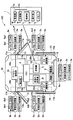
- FIG. 1 illustrates an overall configuration example of a vehicle control device 100 according to an embodiment of the present disclosure.
- the configuration related to the smart system is disclosed in detail in Japanese Patent No. 4581848 (corresponding to US Pat. No. 8,253,534). State.
- the vehicle control device 100 is based on the ID code verification result, the user's operation intention, and the vehicle state based on bidirectional communication between the portable device 1 possessed by the user and the vehicle side unit provided on the vehicle body side of the vehicle 10.
- an ECU 4 corresponding to an ID code determination unit, a condition determination unit, an output unit, a vehicle state acquisition unit, a position specifying unit, a selection unit, a verification unit, and an operation permission unit controls the operation of the opening / closing body (details will be described later).
- the portable device 1 includes a control unit 1c including a well-known CPU, ROM, RAM (all not shown) and the like, and a receiver 1a connected to the control unit 1c for receiving a polling signal from the vehicle side unit, Transmitter 1b for transmitting a response signal including an ID code to respond to this polling signal, operation unit 1d for user operation, program necessary for operation of portable device 1, and data such as ID code Including a memory 1e.
- the control unit 1c determines whether or not a polling signal has been received based on the received signal of the receiver 1a, generates a response signal including an ID code for verification to respond to the polling signal, 1b is transmitted.
- the operation unit 1d includes, for example, a push switch group serving as a trigger for using the remote keyless entry function. Depending on the operation state, for example, a command signal requesting to lock / unlock or open / close the doors 11 to 14 and unlock or open / close the rear door 15 is transmitted from the transmitter 1b.
- a tablet-type terminal typified by a well-known smartphone (a general term for a portable information terminal equipped with a touch panel on a display portion such as a liquid crystal display and operated with a finger), a mobile phone
- a portable communication terminal or a dedicated portable terminal that only transmits an ID code to a polling signal may be used.
- the ECU 4 includes vehicle interior transmitters 2a to 2e provided in the doors 11 to 15 (corresponding to a polling signal output unit), a vehicle interior transmitter 2f provided in the vehicle interior (corresponding to a polling signal output unit), a vehicle interior Is connected to a receiver 3 (corresponding to an operation intention acquisition unit, an ID code acquisition unit, and an ID code reception unit).
- the vehicle-side unit includes at least an ECU 4, a vehicle exterior transmitter (generally referred to as 2 a to 2 e, hereinafter the same), a vehicle interior transmitter 2 f, and a receiver 3.
- the ECU 4 includes door lock control units 5a to 5e provided on the doors 11 to 15, slide door drive units 7c and 7d, window drive units 11b to 14b, a door mirror drive unit 16, a vehicle state detection unit 18 (FIG. 1). Then, “detection unit” is connected so that data communication is possible.
- “detection unit” is connected so that data communication is possible.
- the connection form either an in-vehicle LAN or a direct line system for direct connection may be used.
- the ECU 4 is configured as a computer including a well-known CPU, ROM, RAM (all not shown), peripheral circuits, and the like.
- the CPU executes the control program stored in the ROM, thereby realizing various functions of the vehicle control device.
- the vehicle interior transmitter and vehicle interior transmitter 2f transmit a polling signal based on a transmission instruction signal from the ECU 4.
- the reach distance of the polling signal is set to about 0.7 to 1.0 m, for example.
- detection areas corresponding to the reach distance of the polling signal are formed around each of the doors 11 to 15, and it is possible to detect which door the holder of the portable device 1 has approached.
- the detection area by the vehicle interior transmitter 2f is set so as to cover the vehicle interior, and detects whether the portable device 1 is in the vehicle interior.
- the receiver 3 is ready to receive a response signal from the portable device 1 in synchronization with the output timing of the polling signal transmission instruction signal to the vehicle interior transmitter and vehicle interior transmitter 2f.
- the response signal received by the receiver 3 is output to the ECU 4.
- the ECU 4 collates the ID code included in the received response signal with the master code stored by itself, and based on the collation result, for example, whether to control the door locking / unlocking operation or not. Judgment is made.
- the above-described configuration is “a polling signal output unit (2a to 2e, 2f) that wirelessly outputs a polling signal for polling the portable device and an ID code transmitted from the portable device based on the reception of the polling signal”
- the ID code receiving unit also serves as the ID code acquiring unit
- the collating unit also serves as the ID code determining unit.
- a configuration that does not share a function with a smart system for example, a predetermined operation is permitted based on a collation result of an ID code
- a predetermined operation is permitted based on a collation result of an ID code
- the receiver 3 receives the operation intention information from the tire side device 30a (see FIG. 3). The received operation intention information is output to the ECU 4.
- the door lock control unit (generic name for 5a to 5e, hereinafter the same) locks or unlocks the doors 11 to 15 based on an instruction signal from the ECU 4, but the holder of the portable device 1 By touching the door handles 6a to 6e of the doors 11 to 15, an unlock standby state in which unlocking is possible is set.
- the door handle (general name of 6a to 6e, hereinafter the same) is provided with touch sensors (indicated as “sensor” in FIG. 1) 6a1 to 6e1, and the holder of the portable device 1 touches the door handle to determine a predetermined value. It is detected that the operation was performed.
- the door handle is also configured as a push switch, and is provided with door lock switches (indicated as “SW” in FIG. 1) 6a2 to 6e2 (as an example of a door lock device) for locking the doors 11 to 15. It is done. Further, the door handles 6a to 6e also operate as antennas of the vehicle interior transmitters 2a to 2e, respectively.
- the sliding door drive units 7c and 7d use a motor as a drive source, and slide type doors (hereinafter referred to as “sliding doors”) 13 and 14 corresponding to the rear seats of the vehicle 10, respectively, according to an open / close signal from the ECU 4. Open and close automatically.
- hinged doors 11 and 12 are provided corresponding to the front seats of the vehicle 10.
- the rear door drive unit 8 uses a motor as a drive source, and automatically opens and closes the flip-up type or side-open type rear door 15 according to an open / close signal from the ECU 4.
- the rear door 15 may be provided with a window and a window driving unit.
- the window driving unit (generic name for 11b to 14b, hereinafter the same) performs opening / closing driving of the windows 11a to 14a of the doors 11 to 14.
- the window driving unit can also perform opening / closing driving based on a control command from the ECU 4 in addition to opening / closing driving of the window based on operation of an operation switch (not shown).
- the door mirror drive unit 16 opens and closes the door mirrors 17a and 17b.
- the door mirror drive unit 16 can also perform opening / closing driving based on a control command from the ECU 4 in addition to opening / closing driving of the door mirrors (generically referred to as 17a and 17b, the same applies hereinafter) based on the operation of a user operation switch (not shown). .
- the door lock switches 6a2 to 6e2, the windows 11a to 14a, the slide doors 13 and 14, the rear door 15, and the door mirrors 17a and 17b correspond to an opening / closing body. With this configuration, it is possible to perform drive control of main opening / closing bodies provided in the vehicle by vibrating the tire.
- -Door lock switch The unlocked state (switch is closed) is the first state, and the locked state (switch is open) is the second state.
- -Window The closed state is the first state, and the open state is the second state.
- the opening of the window in the open state front open, half open, etc.
- -Slide door, rear door The closed state is the first state and the open state is the second state. Similar to the window, the opening degree of the door in the open state can be arbitrarily set.
- Door mirror The closed (retracted) state is the first state, and the open (deployed) state is the second state.
- the vehicle state detection unit 18 is a sensor or switch that detects the state of the vehicle, and includes at least one of the following.
- a shift position sensor that detects the position of a shift lever (not shown) of the vehicle 10.
- a vehicle speed sensor that detects the speed of the vehicle 10.
- a parking brake switch that detects the state of a parking brake (not shown) of the vehicle 10.
- a tachometer that detects the number of revolutions of a prime mover (not shown) including at least one of an engine and a motor.
- a start switch (for example, an ignition switch) that permits starting of the prime mover of the vehicle 10.
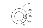
- the wheel 20a includes a tire 21a and a wheel 22a.
- a tire-side device 30a (corresponding to an operation intention detection unit) is provided on the inner side of the tire 21a, for example, near the center in the tire width direction of the tread back surface of the tire 21a (the surface that contacts the road surface).
- the tire side device 30a may be provided inside the wheel 22a as in 40a.
- the tire-side device 30 a includes a vibration detection element 31, a power supply circuit 32 or 33, a signal processing circuit 34, and a transmitter 35.
- the vibration detection element 31 detects, for example, vibration in a direction (tire tangent direction: direction of arrow X in FIG. 2) in contact with a circular orbit drawn by the tire-side device 30a when the tire 21a rotates. Any of the following may be used for the vibration detection element 31.
- Vibration power generation elements that convert vibration energy into electrical energy. Any of an electrostatic induction type power generation element, a piezoelectric element, or a friction type, magnetostriction type, or electromagnetic induction type power generation element may be used.
- strain gauges strain gauges, semiconductor acceleration sensors, differential transformers.
- the operation intention detection unit includes the vibration detection element (31)”.
- the user's intention to operate can be detected with a simple configuration.
- the power supply circuit 33 in the case of using a device that cannot supply the necessary power includes a known battery 33a and a power supply circuit 33b that converts the voltage of the battery 33a into an operating voltage of each part, for example.
- the signal is supplied to the signal processing circuit 34 and the transmitter 35 via the circuit 33b.
- the power supply circuit 32 in the case of using a vibration detection element or a vibration power generation element that does not require external power supply includes a rectification unit 32a and a power storage unit 32b, and converts the power generated by the vibration detection element 31 into a signal processing circuit. 34 and the transmitter 35. In this configuration, the tire side device 30a is operated by the electric power generated by the vibration.
- the rectification unit 32a converts AC power generated by the vibration detection element 31 into DC power and outputs the DC power to the power storage unit 32b, and may be a known full-wave rectification circuit or a half-wave rectification circuit.
- the power storage unit 32b is a circuit for storing the DC power output from the rectification unit 32a and includes, for example, a known capacitor.
- the power storage unit 32b stores the surplus when the vibration detection element 31 generates excessive power, and discharges to compensate for the shortage when the power generation amount is insufficient.
- the signal processing circuit 34 includes a known CPU, ROM, RAM, signal input / output circuit, and a bus connecting them.
- the signal processing circuit 34 includes a vibration section detection unit 34a, a time measurement unit 34b, a high frequency component extraction unit 34c, a determination unit 34d, and a storage unit 34e such as a flash memory as functions for performing signal processing.
- the signal processing circuit 34 determines from the vibration data acquired from the vibration detection element 31 whether or not the vibration is given to the wheel by the user (reflecting the intention of operation) while the vehicle 10 is parked. Output the result.
- the power supply circuit 32 or 33 separates the wakeup signal ( It may be a pulse signal or a rising or falling edge signal) and output to the signal processing circuit 34.
- the signal processing circuit 34 uses the wakeup signal as a trigger to make a transition (wakeup) from a power saving mode (also referred to as a sleep mode) that consumes less power than the normal operation mode to a normal operation mode.
- the mode shifts to the power saving mode. Or stop the operation. Thereby, the power consumption of the tire side device 30a can be reduced, and the burden on the power storage unit 32b or the battery 33a can be reduced.
- the vibration section detector 34a detects a section in which the output voltage of the vibration detection element 31 exceeds a predetermined value as a vibration section.
- the time measurement unit 34b measures the time of the vibration section detected by the vibration section detection unit 34a.
- the high frequency component extraction unit 34c extracts, for example, a high frequency component (high frequency vibration data) in a vibration section using a wavelet filter or a known high pass filter.
- the determination unit 34d determines the cause of vibration based on the time of the vibration section measured by the time measurement unit 34b and the high frequency component extracted by the high frequency component extraction unit 34c.
- the storage unit 34e stores a program and data for the determination unit 34d to determine the operation intention.
- the transmitter 35 transmits the operation intention information output by the determination unit 34d of the signal processing circuit 34 to the vehicle side unit.
- the communication between the transmitter 35 and the receiver 3 included in the vehicle-side unit uses, for example, a known short-range wireless communication technology such as Bluetooth (registered trademark).
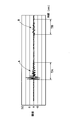
- FIG. 4 shows the output voltage of the vibration detecting element 31 measured by the inventor of the present disclosure when the user gives vibration to the wheel (for example, when the wheel is kicked) and when the door is closed.
- Vibration caused by force applied directly to the wheel such as when the user applies vibration to the wheel, and vibration caused by force applied to the wheel via the vehicle body, such as when the door is closed (waveform B)
- the amplitude, the time of the vibration section (TA, TB), and the high frequency component are different. From this difference, the presence or absence of the user's intention to board is determined.
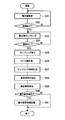
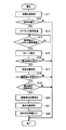
- the operation intention information output process executed in the normal operation mode in the signal processing circuit 34 will be described with reference to FIG.
- the voltage value output by the vibration detection element 31 is acquired (S31).
- it is determined whether or not there is vibration that is, whether or not the state where the voltage value exceeds the value when it is considered that there is no vibration has continued for a predetermined time.
- the voltage value changes S32: Yes
- the voltage value is sampled (S33). That is, the voltage value output by the vibration detection element 31 is acquired and stored in the storage unit 34e.
- S34 Yes
- the sampling of the voltage value is finished (S35).
- the peak value is measured by the vibration section detector 34a (S36)
- the sampling time is measured by the time measurement section 34b (S37)
- the high-frequency component extraction section is extracted (S38) by 34c.
- detection of the user's intention to operate that is, whether or not the vibration is caused by the user is determined (S39). For example, the time, amplitude, and high frequency components of the vibration section when the user applies vibration to the wheel are measured in advance and stored in the storage unit 34e as a reference value or a reference range. When the measured value matches the reference value or is included in the reference range, it is determined that the vibration is caused by the user.
- the threshold value is D (absolute value)
- the vibration section time is TA ⁇ ⁇ ( ⁇ : a value defining the reference range)
- the high-frequency component extracted from the waveform A is the reference value or reference range.
- the vehicle state detected by the vehicle state detection unit 18 is acquired (S11).
- the determination method uses at least one of the following.
- the shift position sensor of the vehicle 10 is in the parking position, it is determined that the vehicle 10 is in the parking state.
- the speed of the vehicle 10 is 0 km / h, it determines with the vehicle 10 being a parking state.
- the parking brake of the vehicle 10 is in the operating state, it is determined that the vehicle 10 is in the parking state.
- the above-described configuration is “provided with a vehicle state acquisition unit (4) for acquiring the vehicle state, and the condition determination unit makes a determination when the vehicle is in a predetermined state”. More specifically, “the condition determining unit determines when the vehicle is in a parked state”. With this configuration, it is possible to prevent the opening / closing body from operating against the user's intention due to the vibration of the running tire.
- the collation result is determined to be normal, and the position of the portable device 1 at this time is specified (S17). That is, it is checked which transmitter (outside the vehicle compartment or in the vehicle interior) the response signal when the normal verification is determined is a response to the polling signal.
- the above-described configuration is “provided with the position specifying unit (4) for specifying the position of the portable device, and the condition determining unit makes a determination when the portable device is not present in the vehicle interior”.
- the portable device When the portable device is present in the vehicle interior, it is considered that the user gets on and performs some operation. According to this configuration, it is possible to prevent the user from competing with the operation of the user.
- the position of the wheel that has detected the vibration is specified (S20). It is assumed that an output condition for outputting the operation command information is satisfied when the collation is normally performed and the operation intention information is received.
- the method for specifying the position of the wheel uses at least one of the following.
- the wheel that is closest to the position of the portable device 1 when the collation is normally performed is the wheel that has detected vibration. Unlike the configuration including the wheel identification information, the association between the wheel identification information and the wheel position is unnecessary.
- the position of the wheel is specified based on the wheel identification information. In this case, the wheel identification information and the wheel position are associated with each other and registered in advance in the ECU 4. When wheel rotation is performed, it is necessary to register again.
- the position of the wheel is specified from the intensity of the radio wave from the transmitter 35 received by the receiver 3.
- an object to be operated is selected from the above-described opening and closing bodies (S21). Any of the following is used as the selection method. Only a specific opening / closing body (for example, only the sliding doors 13 and 14) is set as an operation target. The wheel vibration pattern and the opening / closing body to be operated are associated with each other and stored in the memory of the ECU 4 in advance. Thereby, a plurality of opening / closing bodies can be operated simultaneously. Further, the driver side door can be vibrated to unlock the passenger seat door. The wheel position where the vibration is detected and the opening / closing body to be operated are associated with each other and stored in the memory of the ECU 4 in advance. For example, the door is locked / unlocked or opened / closed near the position of the wheel where the vibration is detected.
- These two configurations are “equipped with a selection unit (4) for selecting an opening / closing body that commands an operation based on a detection state of an operation intention”.
- the user can open and close a desired opening / closing body without performing an operation other than vibrating the tire.
- the position of the portable device 1 when the collation is normally performed and the opening / closing body to be operated are associated with each other and stored in the memory of the ECU 4 in advance.
- a plurality of opening / closing bodies can be operated simultaneously.
- This configuration includes “a position specifying unit (4) that specifies the position of the portable device and a selection unit (4) that selects an opening / closing body that commands operation based on the position of the portable device”. .
- the user can open and close a desired opening / closing body without performing an operation other than vibrating the tire.
- the operation command information is output to the drive unit of the opening / closing body that is the operation target (S22).
- the operation command information includes the fact that the first state and the second state are switched cyclically.
- the above-mentioned configuration is “the opening / closing body includes a first state and a second state different from the first state, and the operation command information includes cyclic switching between the first state and the second state” It is. With this configuration, it is possible to prevent the state management of the opening / closing body from becoming complicated.
- the state of each open / close body is acquired and stored in the memory of the ECU 4. If the state is the first state, the second state is set. The operation command information indicating the state is output.
- each open / close body is respectively connected to the respective open / close bodies.
- the drive units door lock control units 5a to 5e, window drive units 11b to 14b, slide door drive units 7c and 7d, rear door drive unit 8 and door mirror drive unit 16
- the first state may be switched to the second state, and the second state may be switched to the first state for driving.
Landscapes
- Engineering & Computer Science (AREA)
- Mechanical Engineering (AREA)
- Lock And Its Accessories (AREA)
Priority Applications (1)
| Application Number | Priority Date | Filing Date | Title |
|---|---|---|---|
| US15/100,466 US9764714B2 (en) | 2013-12-03 | 2014-11-19 | Vehicular control device |
Applications Claiming Priority (2)
| Application Number | Priority Date | Filing Date | Title |
|---|---|---|---|
| JP2013-249767 | 2013-12-03 | ||
| JP2013249767A JP6235885B2 (ja) | 2013-12-03 | 2013-12-03 | 車両用制御装置 |
Publications (1)
| Publication Number | Publication Date |
|---|---|
| WO2015083335A1 true WO2015083335A1 (ja) | 2015-06-11 |
Family
ID=53273120
Family Applications (1)
| Application Number | Title | Priority Date | Filing Date |
|---|---|---|---|
| PCT/JP2014/005798 Ceased WO2015083335A1 (ja) | 2013-12-03 | 2014-11-19 | 車両用制御装置 |
Country Status (3)
| Country | Link |
|---|---|
| US (1) | US9764714B2 (enExample) |
| JP (1) | JP6235885B2 (enExample) |
| WO (1) | WO2015083335A1 (enExample) |
Families Citing this family (5)
| Publication number | Priority date | Publication date | Assignee | Title |
|---|---|---|---|---|
| US10384519B1 (en) | 2016-01-12 | 2019-08-20 | Apple Inc. | Doors with adaptive positioning |
| JP6631552B2 (ja) * | 2017-02-07 | 2020-01-15 | トヨタ自動車株式会社 | 車両制御システム |
| US10124768B1 (en) * | 2017-05-09 | 2018-11-13 | Robert Bosch Gmbh | Bluetooth low energy (BLE) passive vehicle access control system for defending the system against relay attacks and method thereof |
| CN111192378B (zh) * | 2018-11-15 | 2022-01-28 | 中兴通讯股份有限公司 | 一种车辆移动识别方法、装置及车辆告警系统 |
| KR102652461B1 (ko) * | 2021-12-24 | 2024-03-28 | 주식회사 유라코퍼레이션 | 차량의 도어락 해제 시스템 및 그 방법 |
Citations (6)
| Publication number | Priority date | Publication date | Assignee | Title |
|---|---|---|---|---|
| JP2001234653A (ja) * | 1999-11-09 | 2001-08-31 | Mazda Motor Corp | 車両の開閉体制御装置 |
| JP2004132042A (ja) * | 2002-10-10 | 2004-04-30 | Fuji Heavy Ind Ltd | キーレスエントリーシステム |
| JP2004316231A (ja) * | 2003-04-16 | 2004-11-11 | Nissan Motor Co Ltd | 自動ドアオープナーシステム |
| JP2010133099A (ja) * | 2008-12-03 | 2010-06-17 | Panasonic Corp | 無線装置、その制御方法、およびプログラム |
| JP2012017558A (ja) * | 2010-07-06 | 2012-01-26 | Denso Corp | 制御システム |
| JP2013167150A (ja) * | 2013-03-18 | 2013-08-29 | Tokai Rika Co Ltd | 施解錠操作検出装置 |
Family Cites Families (10)
| Publication number | Priority date | Publication date | Assignee | Title |
|---|---|---|---|---|
| JP4439985B2 (ja) | 2004-04-20 | 2010-03-24 | 株式会社ブリヂストン | 路面摩擦係数の推定方法、路面摩擦係数推定装置、及び、車両制御装置 |
| US8131420B2 (en) * | 2008-02-27 | 2012-03-06 | Simmonds Precision Products, Inc. | Vehicle health and usage monitoring system and method |
| JP4561848B2 (ja) | 2008-03-06 | 2010-10-13 | 株式会社デンソー | 車両ドア制御システム |
| JP5131544B2 (ja) * | 2008-06-26 | 2013-01-30 | アイシン精機株式会社 | 車両用ドアシステム制御装置 |
| JP5265440B2 (ja) | 2009-04-06 | 2013-08-14 | 矢崎エナジーシステム株式会社 | 積載重量推定装置 |
| JP2012025253A (ja) * | 2010-07-22 | 2012-02-09 | Denso Corp | 車両用制御システム |
| JP2012112196A (ja) | 2010-11-26 | 2012-06-14 | Denso Corp | 電子キーシステム |
| JP2013028903A (ja) | 2011-07-27 | 2013-02-07 | Aisin Seiki Co Ltd | 車両用ドア開閉装置 |
| KR20130066348A (ko) * | 2011-12-12 | 2013-06-20 | 현대자동차주식회사 | 차량의 핸즈프리 시스템 제어방법 |
| DE112014001372T5 (de) | 2013-03-15 | 2015-12-03 | Denso Corporation | Reifenvorrichtung |
-
2013
- 2013-12-03 JP JP2013249767A patent/JP6235885B2/ja not_active Expired - Fee Related
-
2014
- 2014-11-19 US US15/100,466 patent/US9764714B2/en not_active Expired - Fee Related
- 2014-11-19 WO PCT/JP2014/005798 patent/WO2015083335A1/ja not_active Ceased
Patent Citations (6)
| Publication number | Priority date | Publication date | Assignee | Title |
|---|---|---|---|---|
| JP2001234653A (ja) * | 1999-11-09 | 2001-08-31 | Mazda Motor Corp | 車両の開閉体制御装置 |
| JP2004132042A (ja) * | 2002-10-10 | 2004-04-30 | Fuji Heavy Ind Ltd | キーレスエントリーシステム |
| JP2004316231A (ja) * | 2003-04-16 | 2004-11-11 | Nissan Motor Co Ltd | 自動ドアオープナーシステム |
| JP2010133099A (ja) * | 2008-12-03 | 2010-06-17 | Panasonic Corp | 無線装置、その制御方法、およびプログラム |
| JP2012017558A (ja) * | 2010-07-06 | 2012-01-26 | Denso Corp | 制御システム |
| JP2013167150A (ja) * | 2013-03-18 | 2013-08-29 | Tokai Rika Co Ltd | 施解錠操作検出装置 |
Also Published As
| Publication number | Publication date |
|---|---|
| US20160297399A1 (en) | 2016-10-13 |
| US9764714B2 (en) | 2017-09-19 |
| JP6235885B2 (ja) | 2017-11-22 |
| JP2015105563A (ja) | 2015-06-08 |
Similar Documents
| Publication | Publication Date | Title |
|---|---|---|
| CN209904701U (zh) | 一种搭配智能钥匙的车辆控制系统 | |
| CN105398420B (zh) | 一种汽车无钥匙进入系统检测方法 | |
| US9972150B2 (en) | Method of verifying user intent in activation of a device in a vehicle | |
| US11267439B2 (en) | Activation of valet mode for vehicles | |
| JP5946018B2 (ja) | 車両ドア開閉システム | |
| CN114590222A (zh) | 具有双因素认证的被动进入被动起动验证 | |
| US20160039365A1 (en) | Systems and Methods for Sending A Message From Tire Pressure Monitoring System to Body Electronics | |
| US9008861B2 (en) | Vehicle device control system with a disabling feature | |
| JP5556784B2 (ja) | 車両制御システムおよび携帯機 | |
| JP6235885B2 (ja) | 車両用制御装置 | |
| CN110065347A (zh) | 轮胎压力测量系统的启动 | |
| CN104903157A (zh) | 车辆进入系统和方法 | |
| JP2012504716A (ja) | 自動車の開閉パネルの自動的ロック解除装置 | |
| JP5381515B2 (ja) | 自動施錠装置 | |
| CN109080580A (zh) | 车辆点火系统和方法 | |
| US9377764B2 (en) | Plug lock device | |
| WO2018003345A1 (ja) | 乗員検知システム及び乗員検知装置 | |
| KR100699721B1 (ko) | 차량용 패시브 도어/시동 장치 | |
| CN110650450A (zh) | 用于车辆通信的具有飞行时间的无线反向散射 | |
| WO2016181631A1 (ja) | スマートエントリーシステム | |
| JP6016089B2 (ja) | スマートシステム | |
| KR100958746B1 (ko) | 수동 키 및 스마트 키를 이용한 차량 제어 방법 및 이를 이용한 차량 및 스마트 키 신호 처리기 | |
| JP5168052B2 (ja) | スマートエントリシステム | |
| JP2014151846A (ja) | 車両用消費電力低減装置 | |
| JP4952358B2 (ja) | 車両用ユーザー照合システム |
Legal Events
| Date | Code | Title | Description |
|---|---|---|---|
| 121 | Ep: the epo has been informed by wipo that ep was designated in this application |
Ref document number: 14868002 Country of ref document: EP Kind code of ref document: A1 |
|
| WWE | Wipo information: entry into national phase |
Ref document number: 15100466 Country of ref document: US |
|
| NENP | Non-entry into the national phase |
Ref country code: DE |
|
| 122 | Ep: pct application non-entry in european phase |
Ref document number: 14868002 Country of ref document: EP Kind code of ref document: A1 |