WO2015083295A1 - 車両用座席 - Google Patents
車両用座席 Download PDFInfo
- Publication number
- WO2015083295A1 WO2015083295A1 PCT/JP2013/082874 JP2013082874W WO2015083295A1 WO 2015083295 A1 WO2015083295 A1 WO 2015083295A1 JP 2013082874 W JP2013082874 W JP 2013082874W WO 2015083295 A1 WO2015083295 A1 WO 2015083295A1
- Authority
- WO
- WIPO (PCT)
- Prior art keywords
- skin material
- side wall
- skin
- wall portion
- seat cushion
- Prior art date
- Legal status (The legal status is an assumption and is not a legal conclusion. Google has not performed a legal analysis and makes no representation as to the accuracy of the status listed.)
- Ceased
Links
Images

Classifications
-
- B—PERFORMING OPERATIONS; TRANSPORTING
- B60—VEHICLES IN GENERAL
- B60N—SEATS SPECIALLY ADAPTED FOR VEHICLES; VEHICLE PASSENGER ACCOMMODATION NOT OTHERWISE PROVIDED FOR
- B60N2/00—Seats specially adapted for vehicles; Arrangement or mounting of seats in vehicles
- B60N2/58—Seat coverings
- B60N2/60—Removable protective coverings
- B60N2/6009—Removable protective coverings covering more than only the seat
-
- B—PERFORMING OPERATIONS; TRANSPORTING
- B60—VEHICLES IN GENERAL
- B60N—SEATS SPECIALLY ADAPTED FOR VEHICLES; VEHICLE PASSENGER ACCOMMODATION NOT OTHERWISE PROVIDED FOR
- B60N2/00—Seats specially adapted for vehicles; Arrangement or mounting of seats in vehicles
- B60N2/58—Seat coverings
- B60N2/5891—Seat coverings characterised by the manufacturing process; manufacturing seat coverings not otherwise provided for
-
- B—PERFORMING OPERATIONS; TRANSPORTING
- B60—VEHICLES IN GENERAL
- B60N—SEATS SPECIALLY ADAPTED FOR VEHICLES; VEHICLE PASSENGER ACCOMMODATION NOT OTHERWISE PROVIDED FOR
- B60N2/00—Seats specially adapted for vehicles; Arrangement or mounting of seats in vehicles
- B60N2/90—Details or parts not otherwise provided for
- B60N2/986—Side-rests
Definitions
- the present invention relates to a vehicle seat disposed in a room of a vehicle such as an automobile, and more particularly to a vehicle seat provided with external parts on the outside of a side wall portion of a seat cushion.
- Patent Documents 1 and 2 Conventionally, there are, for example, Patent Documents 1 and 2 as vehicle seats.
- the skin composite material provided with the reinforcing material on the back surface of the skin material is used.
- the reinforcement is not arranged or the thickness is reduced so as to reduce the surface pressure concentration on the overlapping portion. It has become.
- Patent Document 2 a plurality of skin pieces formed by laminating a skin material and a pad material are stitched together at the respective end portions to form a skin material. And after removing a pad material from the terminal part of a skin piece, several skin pieces are stitched
- the present invention provides a vehicle seat that can improve the durability of the skin material on the side wall of the seat cushion.
- a pad material provided inside a seat cushion, a skin material covering the pad material, and a seat width direction outer side of a lower portion of the skin material covering a side wall portion of the pad material are provided.
- the seat width direction outer side of the lower part of the skin covering the side wall of the pad material provided inside the seat cushion In some cases, a portion of the skin material that is above the appearance component is sandwiched and crushed between the appearance component provided to the occupant and the occupant's buttocks or thigh.
- a reinforcing material is attached to the back surface side of the side wall portion of the skin material that is above the external part, and the upper end portion of the reinforcing material is fixed to the skin material.
- the reinforcing material on the back side of the portion of the skin material bent by crushing is flexibly bent along the bent shape of the skin material. Accordingly, the radius of curvature of the portion of the skin material bent by crushing is increased by the reinforcing material, and the elasticity of the portion of the skin material bent by crushing is also increased by the reinforcing material. As a result, the fold of the crushed skin material portion is reduced, and the restoring force against the crushed is improved. Therefore, even when the skin material is repeatedly crushed, whitening or breakage of the crease hardly occurs in the skin material, and the durability performance of the skin material on the side wall portion of the seat cushion is improved.
- the reinforcing material may be fixed to the skin material in the vicinity of the upper end and the vicinity of the lower end.
- the seat width direction outer side of the lower part of the skin covering the side wall of the pad material provided inside the seat cushion In some cases, a portion of the skin material that is above the appearance component is sandwiched and crushed between the appearance component provided to the occupant and the occupant's buttocks or thigh.
- a reinforcing material is attached to the back surface side of the side wall portion of the skin material that is above the external parts, and the reinforcing material is fixed to the skin material near the upper end and the lower end.
- the reinforcing material on the back side of the portion of the skin material bent by crushing is flexibly bent along the bent shape of the skin material. Accordingly, the radius of curvature of the portion of the skin material bent by crushing is increased by the reinforcing material, and the elasticity of the portion of the skin material bent by crushing is also increased by the reinforcing material. As a result, the fold of the crushed skin material portion is reduced, and the restoring force against the crushed is improved. Therefore, even when the skin material is repeatedly crushed, whitening or breakage of the crease hardly occurs in the skin material, and the durability performance of the skin material on the side wall portion of the seat cushion is improved.
- the reinforcing material is attached to a part of the back surface side of the side wall portion of the skin material that is above the external component. Also good.
- the seat width direction outer side of the lower part of the skin covering the side wall of the pad material provided inside the seat cushion In some cases, a portion of the skin material that is above the appearance component is sandwiched and crushed between the appearance component provided to the occupant and the occupant's buttocks or thigh.
- a reinforcing material is attached to a part of the back surface side of the side wall portion of the skin material that is above the external part. For this reason, the reinforcing material on the back side of the portion of the skin material bent by crushing is flexibly bent along the bent shape of the skin material.
- the radius of curvature of the portion of the skin material bent by crushing is increased by the reinforcing material, and the elasticity of the portion of the skin material bent by crushing is also increased by the reinforcing material.
- the fold of the crushed skin material portion is reduced, and the restoring force against the crushed is improved. Therefore, even when the skin material is repeatedly crushed, whitening or breakage of the crease hardly occurs in the skin material, and the durability performance of the skin material on the side wall portion of the seat cushion is improved.
- the reinforcing material may be thicker than the skin material.
- the reinforcing material is thicker than the skin material, the radius of curvature of the portion bent by the collapse of the skin material is further increased by the reinforcing material, and the elasticity is further increased.
- the crease of the skin material when crushed is greatly reduced, and the restoring force against the crushed is greatly improved, so that the skin material is further less likely to be whitened or broken. Therefore, the durability performance of the skin material in the side wall portion of the seat cushion can be further improved.
- the skin material may have a multilayer structure.
- the starting point of peeling between the layers of the skin material is hardly generated, and peeling between the layers of the skin material can be prevented.
- the seat cushion has a left and right side support portions provided on both sides in the seat width direction, and the body in the center portion in the seat width direction. You may protrude above the part.
- the occupant's buttocks or thighs are provided on both sides of the seat cushion in the seat width direction, and protrude upward from the main body portion of the seat cushion in the center of the seat width direction.
- the left and right side support parts, the external parts provided on the outer side in the seat width direction of the lower part of the skin covering the side wall part of the pad material provided inside the seat cushion, and the occupant's buttocks or thighs In some cases, a portion of the skin material that is above the appearance part is sandwiched and crushed. At this time, a reinforcing material is attached to the entire area of the back surface side of the side wall portion of the skin material.
- the reinforcing material on the back side of the portion of the skin material bent by crushing is flexibly bent along the bent shape of the skin material. Accordingly, the radius of curvature of the portion of the skin material bent by crushing is increased by the reinforcing material, and the elasticity of the portion of the skin material bent by crushing is also increased by the reinforcing material. As a result, the fold of the crushed skin material portion is reduced, and the restoring force against the crushed is improved. Therefore, even when the skin material is repeatedly crushed, whitening or breakage of the crease hardly occurs in the skin material, and the durability performance of the skin material on the side wall portion of the seat cushion is improved.
- the first aspect of the present invention is configured as described above, it is possible to improve the durability performance of the skin material on the side wall portion of the seat cushion.
- the second aspect of the present invention is configured as described above, it is possible to improve the durability performance of the skin material on the side wall portion of the seat cushion.
- the third aspect of the present invention is configured as described above, it is possible to improve the durability performance of the skin material on the side wall portion of the seat cushion.
- the fourth aspect of the present invention is configured as described above, it is possible to further improve the durability of the skin material on the side wall portion of the seat cushion.
- the fifth aspect of the present invention is configured as described above, it is possible to prevent delamination between the layers of the multi-layered skin material.
- the sixth aspect of the present invention is configured as described above, it is possible to improve the durability performance of the skin material on the side wall portion of the seat cushion.
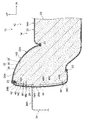
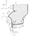
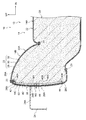
- FIG. 4 is an enlarged cross-sectional view taken along the line 1-1 in FIG. 3. It is sectional drawing corresponding to FIG. 1 which shows the state which the skin material of the vehicle seat which concerns on 1st Embodiment of this invention was crushed. It is the perspective view seen from the slant front outer side which shows the vehicle seat which concerns on 1st Embodiment of this invention. It is sectional drawing corresponding to FIG. 1 which shows the vehicle seat which concerns on 2nd Embodiment of this invention.
- FIGS. a first embodiment of a vehicle seat according to the present invention will be described with reference to FIGS.
- members (components) having the same or corresponding functions are denoted by the same reference numerals and description thereof is omitted as appropriate.
- an arrow FR appropriately shown in the drawings indicates the front of the vehicle seat of the present embodiment
- an arrow UP indicates the upper side
- an arrow IN indicates the inner side in the width direction.
- the vehicle seat demonstrated below is applied to the vehicle seat arrange
- the vehicle seat 10 includes a seat body 12.
- the seat body 12 includes a seat cushion 14 on which an occupant is seated, and a seat back 16 that is connected to the rear end of the seat cushion 14 and supports the back of the seated occupant.
- a headrest 18 that supports the head of the seated occupant is attached to the upper end of the seat back 16.
- the seat cushion 14 includes a main body portion 14A that supports the seat occupant's buttocks and thighs from below, and left and right side support portions 14B that are provided on both sides of the main body portion 14A in the seat width direction. ing.
- the left and right side support portions 14B protrude upward from the main body portion 14A, and are configured to support the buttocks and thighs of the seated occupant from the side.
- the seat cushion 14 is configured symmetrically, the right side portion of the seat cushion 14 will be described below, and the description of the left side portion of the seat cushion 14 will be omitted.
- a urethane pad 20 (seat cushion pad) as a pad material is provided inside the seat cushion 14.
- the urethane pad 20 is a seat (not shown) that is a skeleton member of the seat cushion 14. Supported by the cushion frame.
- the urethane pad 20 is covered with a skin material 22 provided on the outer peripheral portion of the seat cushion 20, and the skin material 22 has a plurality of skin pieces sewn with sutures 23. That is, the urethane pad 20 is provided on the inner side of the skin material 22 composed of a plurality of skin pieces.
- the part which comprises the side support part 14B in the urethane pad 20 is the pad side part 20A
- the part which comprises the side support part 14B in the skin material 22 is the skin side part 22A
- a portion of the skin material 22 that covers the side wall portion of the urethane pad 20 constituting the side wall portion 14 ⁇ / b> C of the seat cushion 14 is a side wall portion (gusset portion) 26 of the skin material 22.
- a resin cover 24 as an external part is provided on the outer side in the seat width direction of the side wall portion 14C of the seat cushion 14.
- the cover 24 is provided on the outer side in the sheet width direction of the lower portion 26 ⁇ / b> A in the side wall portion 26 of the skin material 22.
- An upper wall portion 24A is formed at the upper end of the cover 24 from the outer side in the sheet width direction toward the inner side in the sheet width direction.
- tip (sheet width direction inner side end) 24B of upper wall part 24A has contacted the side wall part 26 of the skin material 22 from the sheet width direction outer side.
- the skin material 22 of the present embodiment has, as an example, a three-layer structure including a fabric 28 as a surface material, a sponge urethane 30 as a pad material, and a thin fabric 32 as a backing material from the surface side. By melting 30, the layers are bonded together by welding.
- the bonding method of the layers in the skin material 22 may be other methods such as bonding using an adhesive instead of welding and sewing with a suture.
- the skin material 22 may have a two-layer structure composed of a fabric 28 as a surface material and sponge urethane 30 as a pad material, or a single-layer structure such as fabric, leather, or synthetic leather.
- a reinforcing material 40 is attached at least in a range on the back surface side above the cover 24.
- the reinforcing member 40 is attached to the entire region from the upper end portion 26B to the lower end portion 26C of the side wall portion 26 of the skin material 22.
- the thickness M1 of the reinforcing material 40 is thicker than the thickness M2 of the skin material 22 (M1> M2), and is comprised with a nonwoven fabric, a textile fabric, etc.
- the vicinity of the upper end portion 40 ⁇ / b> A is fixed to the upper end portion 26 ⁇ / b> B of the side wall portion 26 of the skin material 22 by sewing with a thread 42
- the lower end portion vicinity 40 ⁇ / b> B is the lower end of the side wall portion 26 of the skin material 22. It is fixed to the vicinity 26C by sewing with a thread 44. That is, in the reinforcing member 40, the upper end portion vicinity 40 ⁇ / b> A and the lower end portion vicinity 40 ⁇ / b> B are fixed to the side wall portion 26 of the skin material 22 except for the vertical middle portion 40 ⁇ / b> C.
- the vicinity of the lower end portion 40 ⁇ / b> B of the reinforcing member 40 may be a position closer to the lower side than the upper wall portion 24 ⁇ / b> A of the cover 24. Furthermore, when the reinforcing member 40 is small, only the vicinity of the upper end portion 40 ⁇ / b> A may be fixed to the side wall portion 26 of the skin material 22. Further, the reinforcing member 40 may be sewn simultaneously with the skin piece of the skin material 22 by the suture thread 23. Further, the reinforcing material 40 may be fixed to the skin material 22 by welding or an adhesive.
- the curvature radius of the part 26D bent by the crushing in the side wall part 26 of the skin material 22 is increased by the reinforcing material 40 as compared with the curvature radius when the reinforcing material 40 is not provided. Further, the elasticity of the portion 26D bent by the crushing in the side wall portion 26 of the skin material 22 is also increased as compared with the case where the reinforcing material 40 is not provided.
- the reinforcing material 40 is attached to the back surface side above the cover 24 in the side wall portion 26 of the skin material 22, and the reinforcing material 40 excludes the vertical intermediate portion 40 ⁇ / b> C.
- the upper end vicinity 40 ⁇ / b> A and the lower end vicinity 40 ⁇ / b> B are fixed to the side wall portion 26 of the skin material 22.
- the reinforcing material 40 on the back surface side of the portion 22 ⁇ / b> D of the skin material 22 that is bent due to crushing is flexibly bent along the bent shape of the skin material 22.
- the radius of curvature of the part 26D bent by the collapse in the side wall portion 26 of the skin material 22 is increased by the reinforcing material 40 as compared with the radius of curvature when the reinforcing material 40 is not provided.
- the elasticity of the portion 26 ⁇ / b> D bent by the collapse of the side wall portion 26 of the skin material 22 is increased by the reinforcing material 40 as compared with the case where the reinforcing material 40 is not provided.
- the fold of the portion 26D of the side wall portion 26 of the skin material 22 when being crushed is reduced, and the restoring force against the crushed is also improved. Therefore, whitening or breakage of the crease hardly occurs in the side wall portion 26 of the skin material 22, and the durability performance of the side wall portion 26 of the skin material 22 in the side wall portion 14 ⁇ / b> C of the seat cushion 14 can be improved.
- the thickness M1 of the reinforcing material 40 is larger than the thickness M2 of the skin material 22 (M1> M2). For this reason, the curvature radius of the part 26D bent by the crushing in the side wall portion 26 of the skin material 22 is significantly increased by the reinforcing material 40 as compared with the curvature radius when the reinforcing material 40 is not provided. Moreover, the elasticity of the part 26D bent by the crushing in the side wall part 26 of the skin material 22 is also greatly increased as compared with the case where the reinforcing material 40 is not provided. Therefore, whitening or breakage of the crease is less likely to occur in the side wall portion 26 of the skin material 22, and the durability performance of the skin material 22 in the side wall portion 14C of the seat cushion 14 can be further improved.
- the skin material 22 has a three-layer structure including a fabric 28, sponge urethane 30, and a thin fabric 32 from the surface side, and the layers are bonded to each other by dissolving the sponge urethane 30. Yes. For this reason, when the site
- the raised hair 50 may be formed on the surface of the reinforcing member 40 on the side in contact with the skin material 22 as in the second embodiment.
- the raised force 50 of the reinforcing member 40 can further improve the restoring force against crushing in the side wall portion 26 of the skin material 22.
- the thickness M1 of the reinforcing material 40 is made thicker than the thickness M2 of the skin material 22 (M1> M2), but instead, the thickness M1 of the reinforcing material 40 is changed to the thickness of the skin material 22.
Landscapes
- Engineering & Computer Science (AREA)
- Aviation & Aerospace Engineering (AREA)
- Transportation (AREA)
- Mechanical Engineering (AREA)
- Seats For Vehicles (AREA)
Abstract
Description
次に、本発明の車両用座席の第1実施形態を図1~図3に従って説明する。
なお、図中、同一又は対応する機能を有する部材(構成要素)には同じ符号を付して適宜説明を省略する。また、図面に適宜示される矢印FRは本実施形態の車両用座席の前方を示し、矢印UPは上方を示し、矢印INは幅方向内側を示している。また、以下説明する車両用座席は、一例として車両(自動車)の右側部分に配置された車両用座席に適用されている。
次に、本実施形態の作用及び効果について説明する。
車両用座席10では、乗員の乗降時等に、乗員の臀部又は大腿部Dが、シートクッション14のサイドサポート部14Bに当たると、図2に示すように、乗員の臀部又は大腿部Dとカバー24の上壁部24Aとの間に表皮材22の側壁部26におけるカバー24より上方となる部分が挟まれ潰されることがある。
以上に於いては、本発明を特定の実施形態について詳細に説明したが、本発明は上記各実施形態に限定されるものではなく、本発明の範囲内にて他の種々の実施形態が可能であることは当業者にとって明らかである。例えば、図4に示すように、第2実施形態のように、補強材40における表皮材22と接触する側の面に起毛50が形成されていてもよい。なお、この場合には、補強材40の起毛50によって、表皮材22の側壁部26における潰れに対する復元力をさらに向上させることができる。
Claims (6)
- シートクッションの内側に設けられたパッド材と、
前記パッド材を覆う表皮材と、
前記パッド材の側壁部を覆う前記表皮材の下部のシート幅方向外側に設けられた外観部品と、
前記外観部品より上方となる前記表皮材の側壁部の裏面側に取付けられ、上端部付近が前記表皮材に固定された補強材と、
を有する車両用座席。 - 前記補強材は、上端部付近と下端部付近とが前記表皮材に固定されている請求項1に記載の車両用座席。
- 前記補強材は、前記外観部品より上方となる前記表皮材の側壁部の裏面側の一部に取付けられている請求項1又請求項2に記載の車両用座席。
- 前記補強材は前記表皮材より厚い請求項1~3の何れか1項に記載の車両用座席。
- 前記表皮材は多層構造である請求項1~4の何れか1項に記載の車両用座席。
- 前記シートクッションはシート幅方向両側に設けられた左右のサイドサポート部が、シート幅方向中央部の本体部よりも上側へ突出している請求項1~5何れか1項に記載の車両用座席。
Priority Applications (4)
| Application Number | Priority Date | Filing Date | Title |
|---|---|---|---|
| JP2015551365A JPWO2015083295A1 (ja) | 2013-12-06 | 2013-12-06 | 車両用座席 |
| PCT/JP2013/082874 WO2015083295A1 (ja) | 2013-12-06 | 2013-12-06 | 車両用座席 |
| MX2016007264A MX2016007264A (es) | 2013-12-06 | 2013-12-06 | Asiento de vehiculo. |
| CN201380081305.3A CN105793103A (zh) | 2013-12-06 | 2013-12-06 | 车辆用座席 |
Applications Claiming Priority (1)
| Application Number | Priority Date | Filing Date | Title |
|---|---|---|---|
| PCT/JP2013/082874 WO2015083295A1 (ja) | 2013-12-06 | 2013-12-06 | 車両用座席 |
Publications (1)
| Publication Number | Publication Date |
|---|---|
| WO2015083295A1 true WO2015083295A1 (ja) | 2015-06-11 |
Family
ID=53273087
Family Applications (1)
| Application Number | Title | Priority Date | Filing Date |
|---|---|---|---|
| PCT/JP2013/082874 Ceased WO2015083295A1 (ja) | 2013-12-06 | 2013-12-06 | 車両用座席 |
Country Status (4)
| Country | Link |
|---|---|
| JP (1) | JPWO2015083295A1 (ja) |
| CN (1) | CN105793103A (ja) |
| MX (1) | MX2016007264A (ja) |
| WO (1) | WO2015083295A1 (ja) |
Cited By (2)
| Publication number | Priority date | Publication date | Assignee | Title |
|---|---|---|---|---|
| JP2019182163A (ja) * | 2018-04-09 | 2019-10-24 | 株式会社タチエス | 車両用シート |
| JP7626591B2 (ja) | 2020-02-04 | 2025-02-04 | トヨタ自動車株式会社 | 車両用シート |
Citations (4)
| Publication number | Priority date | Publication date | Assignee | Title |
|---|---|---|---|---|
| JPH01159646A (ja) * | 1987-12-17 | 1989-06-22 | Fuji Photo Film Co Ltd | ハロゲン化銀カラー写真感光材料およびその処理法 |
| JP2011173539A (ja) * | 2010-02-25 | 2011-09-08 | Toyota Boshoku Corp | 車両用シートカバー |
| JP2013091457A (ja) * | 2011-10-26 | 2013-05-16 | Honda Motor Co Ltd | バックル保持装置 |
| JP5327337B2 (ja) * | 2010-09-22 | 2013-10-30 | トヨタ自動車株式会社 | 車両用シート |
Family Cites Families (6)
| Publication number | Priority date | Publication date | Assignee | Title |
|---|---|---|---|---|
| JPS5816840A (ja) * | 1981-07-23 | 1983-01-31 | 池田物産株式会社 | 表皮一体発泡パツドとその成形法 |
| JPH0515795Y2 (ja) * | 1987-10-19 | 1993-04-26 | ||
| US6371562B1 (en) * | 2000-05-12 | 2002-04-16 | Tachi-S Co., Ltd. | Reinforced arrangement in a vehicle seat and method for forming the same |
| JP2003153762A (ja) * | 2001-09-04 | 2003-05-27 | Namba Press Works Co Ltd | 座席用クッション中身体及びその製造方法 |
| JP3914757B2 (ja) * | 2001-11-30 | 2007-05-16 | デュアキシズ株式会社 | ウィルス検査のための装置と方法とシステム |
| JP2013233287A (ja) * | 2012-05-09 | 2013-11-21 | Toyota Boshoku Corp | 車両用シート |
-
2013
- 2013-12-06 WO PCT/JP2013/082874 patent/WO2015083295A1/ja not_active Ceased
- 2013-12-06 CN CN201380081305.3A patent/CN105793103A/zh active Pending
- 2013-12-06 JP JP2015551365A patent/JPWO2015083295A1/ja active Pending
- 2013-12-06 MX MX2016007264A patent/MX2016007264A/es unknown
Patent Citations (4)
| Publication number | Priority date | Publication date | Assignee | Title |
|---|---|---|---|---|
| JPH01159646A (ja) * | 1987-12-17 | 1989-06-22 | Fuji Photo Film Co Ltd | ハロゲン化銀カラー写真感光材料およびその処理法 |
| JP2011173539A (ja) * | 2010-02-25 | 2011-09-08 | Toyota Boshoku Corp | 車両用シートカバー |
| JP5327337B2 (ja) * | 2010-09-22 | 2013-10-30 | トヨタ自動車株式会社 | 車両用シート |
| JP2013091457A (ja) * | 2011-10-26 | 2013-05-16 | Honda Motor Co Ltd | バックル保持装置 |
Cited By (2)
| Publication number | Priority date | Publication date | Assignee | Title |
|---|---|---|---|---|
| JP2019182163A (ja) * | 2018-04-09 | 2019-10-24 | 株式会社タチエス | 車両用シート |
| JP7626591B2 (ja) | 2020-02-04 | 2025-02-04 | トヨタ自動車株式会社 | 車両用シート |
Also Published As
| Publication number | Publication date |
|---|---|
| MX2016007264A (es) | 2016-08-04 |
| CN105793103A (zh) | 2016-07-20 |
| JPWO2015083295A1 (ja) | 2017-03-16 |
Similar Documents
| Publication | Publication Date | Title |
|---|---|---|
| JP5098612B2 (ja) | 乗物用シートの表皮材用ピースおよびその製造方法 | |
| US10227024B2 (en) | Seat cover and vehicle seat | |
| JP6650362B2 (ja) | 車両用シート | |
| JP6488885B2 (ja) | シートカバー | |
| CN107433892A (zh) | 装饰罩及车辆用座椅 | |
| JP6100111B2 (ja) | シートクッション | |
| JP2016067549A (ja) | ワディング材付シートの表皮構造およびワディング材付シートの表皮製造方法 | |
| JP6660803B2 (ja) | 車両用シート | |
| JP5593307B2 (ja) | 車両座席カバー及び車両座席 | |
| WO2015083295A1 (ja) | 車両用座席 | |
| JP2020037288A (ja) | 乗物用シートカバー | |
| JP6316681B2 (ja) | エアベルト装置 | |
| JP2024000363A (ja) | シートカバー及び車両用シート | |
| JP7522081B2 (ja) | シートバックパネル及び車両用シートバック | |
| JP5531590B2 (ja) | 車両用シート | |
| JP2019156085A (ja) | 車両用シート | |
| JP2006262959A (ja) | シートのトリムカバー | |
| JP7356333B2 (ja) | 乗り物用シート | |
| JP5882112B2 (ja) | 車両用シート | |
| JP4556487B2 (ja) | 表皮端部の接合構造 | |
| JP4524089B2 (ja) | 座席構造 | |
| JP6876555B2 (ja) | トリムカバー及び乗物用シート | |
| JP2024125097A (ja) | シートバック | |
| JP7106857B2 (ja) | 乗物用シート | |
| CN105905011A (zh) | 座椅套和座椅套的制造方法以及车用座椅 |
Legal Events
| Date | Code | Title | Description |
|---|---|---|---|
| 121 | Ep: the epo has been informed by wipo that ep was designated in this application |
Ref document number: 13898550 Country of ref document: EP Kind code of ref document: A1 |
|
| ENP | Entry into the national phase |
Ref document number: 2015551365 Country of ref document: JP Kind code of ref document: A |
|
| WWE | Wipo information: entry into national phase |
Ref document number: MX/A/2016/007264 Country of ref document: MX |
|
| NENP | Non-entry into the national phase |
Ref country code: DE |
|
| 122 | Ep: pct application non-entry in european phase |
Ref document number: 13898550 Country of ref document: EP Kind code of ref document: A1 |