WO2015076189A1 - 吸収性物品 - Google Patents
吸収性物品 Download PDFInfo
- Publication number
- WO2015076189A1 WO2015076189A1 PCT/JP2014/080139 JP2014080139W WO2015076189A1 WO 2015076189 A1 WO2015076189 A1 WO 2015076189A1 JP 2014080139 W JP2014080139 W JP 2014080139W WO 2015076189 A1 WO2015076189 A1 WO 2015076189A1
- Authority
- WO
- WIPO (PCT)
- Prior art keywords
- absorbent article
- region
- pressing groove
- marker
- groove
- Prior art date
- Legal status (The legal status is an assumption and is not a legal conclusion. Google has not performed a legal analysis and makes no representation as to the accuracy of the status listed.)
- Ceased
Links
Images
Classifications
-
- A—HUMAN NECESSITIES
- A61—MEDICAL OR VETERINARY SCIENCE; HYGIENE
- A61F—FILTERS IMPLANTABLE INTO BLOOD VESSELS; PROSTHESES; DEVICES PROVIDING PATENCY TO, OR PREVENTING COLLAPSING OF, TUBULAR STRUCTURES OF THE BODY, e.g. STENTS; ORTHOPAEDIC, NURSING OR CONTRACEPTIVE DEVICES; FOMENTATION; TREATMENT OR PROTECTION OF EYES OR EARS; BANDAGES, DRESSINGS OR ABSORBENT PADS; FIRST-AID KITS
- A61F13/00—Bandages or dressings; Absorbent pads
- A61F13/15—Absorbent pads, e.g. sanitary towels, swabs or tampons for external or internal application to the body; Supporting or fastening means therefor; Tampon applicators
- A61F13/84—Accessories, not otherwise provided for, for absorbent pads
-
- A—HUMAN NECESSITIES
- A61—MEDICAL OR VETERINARY SCIENCE; HYGIENE
- A61F—FILTERS IMPLANTABLE INTO BLOOD VESSELS; PROSTHESES; DEVICES PROVIDING PATENCY TO, OR PREVENTING COLLAPSING OF, TUBULAR STRUCTURES OF THE BODY, e.g. STENTS; ORTHOPAEDIC, NURSING OR CONTRACEPTIVE DEVICES; FOMENTATION; TREATMENT OR PROTECTION OF EYES OR EARS; BANDAGES, DRESSINGS OR ABSORBENT PADS; FIRST-AID KITS
- A61F13/00—Bandages or dressings; Absorbent pads
- A61F13/15—Absorbent pads, e.g. sanitary towels, swabs or tampons for external or internal application to the body; Supporting or fastening means therefor; Tampon applicators
- A61F13/45—Absorbent pads, e.g. sanitary towels, swabs or tampons for external or internal application to the body; Supporting or fastening means therefor; Tampon applicators characterised by the shape
- A61F13/47—Sanitary towels, incontinence pads or napkins
- A61F13/475—Sanitary towels, incontinence pads or napkins characterised by edge leakage prevention means
- A61F13/4751—Sanitary towels, incontinence pads or napkins characterised by edge leakage prevention means the means preventing fluid flow in a transversal direction
- A61F13/4756—Sanitary towels, incontinence pads or napkins characterised by edge leakage prevention means the means preventing fluid flow in a transversal direction the means consisting of grooves, e.g. channels, depressions or embossments, resulting in a heterogeneous surface level
-
- A—HUMAN NECESSITIES
- A61—MEDICAL OR VETERINARY SCIENCE; HYGIENE
- A61F—FILTERS IMPLANTABLE INTO BLOOD VESSELS; PROSTHESES; DEVICES PROVIDING PATENCY TO, OR PREVENTING COLLAPSING OF, TUBULAR STRUCTURES OF THE BODY, e.g. STENTS; ORTHOPAEDIC, NURSING OR CONTRACEPTIVE DEVICES; FOMENTATION; TREATMENT OR PROTECTION OF EYES OR EARS; BANDAGES, DRESSINGS OR ABSORBENT PADS; FIRST-AID KITS
- A61F13/00—Bandages or dressings; Absorbent pads
- A61F13/15—Absorbent pads, e.g. sanitary towels, swabs or tampons for external or internal application to the body; Supporting or fastening means therefor; Tampon applicators
- A61F13/84—Accessories, not otherwise provided for, for absorbent pads
- A61F2013/8497—Accessories, not otherwise provided for, for absorbent pads having decorations or indicia means
Definitions
- the present invention relates to absorbent articles such as sanitary napkins and incontinence pads.
- a sanitary napkin in general, includes a top sheet, a back sheet, and an absorber disposed between both sheets, and is disposed on a non-skin facing surface of the back sheet in a crotch portion of clothing such as shorts. Used by fixing with adhesive. When used in this manner, the function of the sanitary napkin cannot be sufficiently exhibited unless the sanitary napkin is arranged and fixed at an appropriate position of the crotch portion of the garment.
- Patent Documents 1 and 2 a sanitary napkin in which a mark formed on a sanitary napkin can be visually confirmed and the sanitary napkin can be arranged at an appropriate position of a crotch portion of clothing based on the mark. Is described.
- the sanitary napkins described in Patent Documents 1 and 2 are for visually confirming the marks, and Patent Documents 1 and 2 do not describe any marks for confirmation with a sense other than visual inspection. Moreover, since the sanitary napkin described in Patent Documents 1 and 2 is based on the premise that the mark is visually confirmed, the leak-proof groove formed by compressing the mark, the surface sheet, and the absorbent body integrally. No consideration is given to the difference.
- the present invention relates to a vertically long absorbent article including a top sheet, a back sheet, and an absorbent body disposed between the two sheets.
- marker part are formed in the skin opposing surface by pressing together the said surface sheet and the said absorber toward the said back surface sheet side.
- the squeezing groove has a lateral squeezing groove extending in the width direction in a rear region of the absorbent article, and the marker part has a size that allows the entire volume of the marker part to be understood when touched with the tip of a finger, and
- the length in the width direction is shorter than the lateral pressing groove, and is arranged on a center line extending in the longitudinal direction of the absorbent article, and is formed in a shape symmetrical to the center line.
- the said marker part is distribute
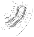
- FIG. 1 is the perspective view which looked at the sanitary napkin which is one Embodiment of this invention from the surface sheet side.
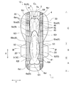
- FIG. 2 is a plan view of the sanitary napkin shown in FIG. 1 as viewed from the top sheet side.
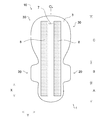
- FIG. 3 is a plan view of the sanitary napkin shown in FIG. 1 as viewed from the back sheet side.
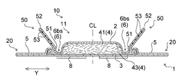
- 4 is a cross-sectional view taken along line IV-IV in FIG.
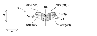
- FIG. 5 is an enlarged plan view of the sign portion of the sanitary napkin shown in FIG. 2 as viewed from the surface sheet side.
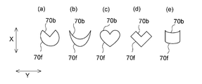
- 6 (a) to 6 (e) are enlarged plan views of other marker portions of the absorbent article of the present invention as viewed from the surface sheet side.
- the absorbent article of the present embodiment is a sanitary napkin, and the sanitary napkin 1 (hereinafter, also referred to as “napkin 1”) of the present embodiment includes a top sheet 2, as shown in FIGS. This is a vertically long sheet including a back sheet 3 and an absorbent body 4 disposed between the two sheets 2 and 3.
- the “skin facing surface” is a surface that is disposed on the skin side of the wearer when wearing, among the front and back surfaces of each member such as the surface sheet 2 constituting the napkin 1,
- the “surface” refers to a surface of the front and back surfaces of each member such as the surface sheet 2 constituting the napkin 1 that is directed to the side opposite to the wearer's skin side when worn, that is, the clothing side.
- the “front-rear direction” is a direction that coincides with the wearer's front-rear direction when worn, and is also a direction that coincides with the longitudinal direction of the napkin 1.
- the front-rear direction or the longitudinal direction is indicated by “X direction” in each drawing.
- the “Y direction” shown in each figure is a direction orthogonal to the X direction, and is the same direction as the left-right direction or the width direction of the napkin 1. As shown in FIG. 1, the napkin 1 is formed symmetrically with respect to a center line CL extending in the longitudinal direction (X direction) of the napkin 1.
- the napkin 1 of the present embodiment is a night napkin suitable for use at bedtime, and preferably has a total length of 30 cm or more, particularly 35 cm or more.
- the napkin 1 has a vertically long absorbent main body 10 that is long in the front-rear direction (X direction), a pair of wing portions 20, 20, and a pair of rear flap portions 30, 30. .
- the napkin 1 is divided into the front area A, the excretory part facing area B, and the rear area C in the front-rear direction (X direction), and a pair of wing parts 20 on the left and right sides of the absorbent main body 10 in the excretory part facing area B. 20.
- a pair of rear flaps 30 and 30 are provided on the left and right sides of the absorbent main body 10 in the rear region C.
- the excretion part facing region B is a region where the wearer's liquid excretion part (vaginal opening or the like) is disposed to face the central region in the width direction (Y direction), and the front region A is The region B is disposed on the front side (abdomen side) of the wearer from the excretion part facing region B, and the rear region B is the region disposed on the back side of the wearer from the excretion part facing region B.
- region which has the wing part 20 in the front-back direction (X direction) of an absorbent article ie, the front-back direction one side of a wing part
- region in the absorbent article which does not have the wing part 20 crosses in the width direction (Y direction) of this absorbent article which arises when an absorbent article is folded by the trifold individual packaging form. Is a region surrounded by a first fold curve and a second fold curve, counting from the front end of the absorbent article in the front-rear direction (X direction).
- the napkin 1 includes a liquid-permeable surface sheet 2 that forms a skin-facing surface, a liquid-impermeable back sheet 3 that forms a non-skin-facing surface, and a space between them.
- a longitudinally long absorbent main body 10 having an absorbent body 4 arranged in the above is provided.
- the absorptive main body 10 includes a pair of three-dimensional guard forming sheets 5 and 5 joined to both the left and right sides of the topsheet 2.
- the surface sheet 2 covers the skin facing surface of the absorbent body 4 in the napkin 1, and the absorbent main body 10 is located at the center in the width direction (Y direction) of the absorbent main body 10. It is distribute
- the back surface sheet 3 covers the entire surface of the non-skin facing surface of the absorbent body 4 as shown in FIGS.
- the front and rear ends of the back sheet 3 in the front-rear direction (X direction) extend outward from the front and rear ends of the absorber 4 in the front-rear direction (X direction).
- Both sides along the front-rear direction (X direction) of the back sheet 3 extend outward in the width direction (Y direction) from the left and right sides of the absorber 4.
- the back surface sheet 3 has the outline which corresponds with the outline of the absorptive main body 10 in the front area
- the extended parts of the back surface sheet 3 in the excretion part opposing region B and the rear region C are materials for forming the wing part 20 and the rear flap part 30, respectively.
- the absorbent body 4 is composed of a fiber aggregate made of a fiber material such as pulp fiber, or upper and lower surfaces of an absorbent core in which a super absorbent polymer is held in the fiber aggregate. It is formed by being covered with a core wrap sheet (not shown).
- the core wrap sheet is used for the purpose of preventing leakage of the forming material of the absorbent core or improving the shape retention of the absorbent core.
- dots and spirals are dots and spirals. In addition, it is preferable that they are bonded to each other by an adhesive applied with a pattern such as a stripe.
- the absorbent body 4 has a shape that is long in the same direction as the front-rear direction (X direction) of the napkin 1, as shown in FIG. Moreover, the absorber 4 has the front middle-high area
- a rear middle-high region 42 is provided at the center in the direction (Y direction). Further, the absorber 4 has an annular peripheral region 43 that collectively surrounds the front middle-high region 41 and the rear middle-high region 42.
- the presence of the front middle-high area 41 of the absorbent body 4 under the top sheet 2 extends from the excretory part facing area B to a part of the rear area C.
- a front raised portion 11 that protrudes toward the wearer's skin is formed at the center in the width direction of the skin-facing surface in the region, and a rear middle-high region 42 of the absorbent body 4 is provided below the top sheet 2.
- a rear raised portion 12 that protrudes toward the skin side of the wearer is formed at the center in the width direction of the skin facing surface in the rear region C.
- the front middle-high region 41 is a region that is thicker than the peripheral region 43 of the absorber 4, and is formed in a region extending from the excretory part facing region B to a part of the rear region C. Yes.
- the front middle-high area 41 may be formed only in the excretion part facing area B, but extends from the excretion part facing area B to a part of the rear area C as shown in FIGS. Preferably it is.
- the rear middle-high region 42 is a region having a thickness larger than the thickness in the peripheral region 43 of the absorber 4, and is formed in the rear region C as shown in FIGS. Further, the rear middle / high region 42 is formed behind the front middle / high region 41 in the front-rear direction (X direction) of the absorber 4.
- the three-dimensional guard forming sheet 5 is disposed along the front-rear direction (X direction) on each of the left and right side portions of the topsheet 2 as shown in FIGS.
- the three-dimensional guard forming sheet 5 has a folded portion 51 that is folded outward at a position near the center line CL in the width direction (Y direction) of the absorbent main body 10. (Y direction) It is joined on the surface sheet 2 in the part located outside.
- the three-dimensional guard forming sheet 5 has an elastic member 53 for forming a three-dimensional guard in the vicinity of the side edge portion 52 that forms the free end of the three-dimensional guard. When worn, the three-dimensional guard forming sheet 5 is excreted by the contraction force of the elastic member 53. A portion between the folded portion 51 and the side edge portion 52 in the part facing region B stands up toward the wearer's skin side to form the three-dimensional guard 50.
- the pair of wing parts 20, 20 and the pair of rear flap parts 30, 30 are composed of a three-dimensional guard forming sheet 5 and a back sheet 3 extending from both side edges of the absorber 4.
- a wing portion adhesive portion (not shown) for fixing to the non-skin facing surface of the crotch portion of the shorts is provided on the surface composed of the back sheet 3 of each of the pair of wing portions 20.
- attachment part (not shown) for fixing to the surface which consists of the back surface sheet 3 of each of a pair of back flap part 30 to the non-skin opposing surface of shorts is provided.
- the outer side of the skin side sheet 2 and the back sheet 3 is joined to each other with an adhesive from the periphery of the absorber 4.
- the skin side sheet 2, the back surface sheet 3, and the three-dimensional guard forming sheet 5 follow the outline of the entire periphery of the napkin 1 having the pair of wing portions 20, 20 and the pair of rear flap portions 30, 30. They are joined by heat sealing.
- marker part 7 squeeze the surface sheet 2 and the absorber 4 integrally toward the back sheet 3 side on the skin opposing surface. Is formed.
- the pressing groove 6 and the label part 7 will be specifically described.
- the pressing groove 6 and the marker part 7 are formed by, for example, pressing by hot embossing or ultrasonic sealing.
- the pressing groove 6 has a lateral pressing groove 6 c extending in the width direction (Y direction) in the rear region C of the napkin 1.
- the squeezing groove 6 is formed on the front squeezing groove 6a disposed in the front area A and on both sides of the area extending from the excretory part facing area B to a part of the rear area C.
- the front pressing groove 6a, the pair of vertical pressing grooves 6bs, 6bs, the pair of vertical pressing grooves 6cs, 6cs and the horizontal pressing groove 6c are connected to form an annular circumferential groove.
- the “lateral pressing groove extending in the width direction (Y direction) in the rear region C of the napkin 1” means that there are a plurality of horizontal pressing grooves extending in the width direction (Y direction) in the rear region C as in the napkin 1.
- a book in the napkin 1, two lateral pressing grooves 6c and a second lateral pressing groove 6d
- it means the lateral pressing groove 6c located at the rearmost position.
- the pressing groove 6 has other grooves in addition to the lateral pressing groove 6c in the napkin 1, it does not need to have other grooves, and the shape of the other grooves is also a shape described later. Not exclusively.
- the forward pressing groove 6 a has an arcuate right convex pressing groove 6 ar projecting convexly rightward and forward on the right side from the center line CL, and convex leftward and forward on the left side from the centerline CL. And an arcuate left convex squeezing groove 6al protruding in a shape.
- the right convex squeezing groove 6ar and the left convex squeezing groove 6al intersect and are connected while forming a recess 61 that is recessed in a V shape on the rear side on the center line CL side.
- the pair of vertical pressing grooves 6bs and 6bs are arranged along both sides of the front middle / high region 41 of the absorber 4 and are arcuately curved outwardly in the width direction (Y direction). Is formed.
- the right convex squeezing groove 6ar and the one vertical squeezing groove 6bs constituting the front squeezing groove 6a intersect and are connected while forming a right constricted part 62r constricted on the center line CL side.
- left convex squeezing groove 6al and the other vertical squeezing groove 6bs constituting the front squeezing groove 6a intersect and are connected while forming a left constricted part 62l constricted to the center line CL side.
- the right side neck portion 62r and the left side neck portion 62l are formed symmetrically with respect to the center line CL.
- the pair of vertical pressing grooves 6cs, 6cs are arranged so as to surround the rear middle / high region 42 of the absorber 4, and are formed in an arc shape that is curved outwardly in the width direction (Y direction).
- Y direction width direction
- one vertical pressing groove 6cs and one vertical pressing groove 6bs intersect and are connected while forming a right intermediate constricted portion 63r that is smoothly constricted on the center line CL side.
- the other vertical pressing groove 6cs and the other vertical pressing groove 6bs intersect and are connected while forming a left intermediate constricted portion 63l that is smoothly constricted toward the center line CL.
- the right intermediate constricted portion 63r and the left intermediate constricted portion 63l are formed symmetrically with respect to the center line CL.
- the lateral pressing groove 6 c has an arcuate right convex pressing groove 6 cr that protrudes in a diagonally rightward rearward direction on the right side from the center line CL, and a left diagonally rearward side on the left side from the central line CL. And an arc-shaped left convex squeezing groove 6cl protruding in a shape.
- the right convex squeezing groove 6cr and the left convex squeezing groove 6cl are crossed and connected to each other while forming a hollow 64 recessed in a V shape on the front side on the center line CL side.
- the right convex squeezing groove 6cr constituting the lateral squeezing groove 6c and one vertical squeezing groove 6cs are smoothly connected while being curved outwardly. Further, the left convex pressing groove 6cl constituting the lateral pressing groove 6c and the other vertical pressing groove 6cs are smoothly connected while being curved outwardly in a convex shape.
- the second lateral pressing groove 6 d is formed in an arc shape that protrudes rearward in a region between the front middle-high region 41 and the rear middle-high region 4 of the absorber 4. . Both end portions of the second lateral pressing groove 6d extend to positions near the right intermediate constricted portion 63r and the left intermediate constricted portion 63l.
- the sign portion 7 is sized so that the entire sign portion 7 can be seen when touched with the tip of a finger, and the width direction (Y direction) length is 6 c horizontal. As shown in FIGS. 2 and 5, it is formed on a center line CL that extends in the longitudinal direction (X direction) of the napkin 1 and is formed in a symmetrical shape with respect to the center line CL. .
- the size that allows the entire portion of the marker portion 7 to be understood when touched with the tip of a finger can be described in detail.
- the outline of the marker portion 7 can be grasped with the toe of the thumb or forefinger.
- the central portion is sized to be grasped, specifically, the area of the label portion 7 is meant of about 0.04cm 2 ⁇ 25cm 2.
- the area of the labeling part 7 is preferably 0.64 cm 2 or more, particularly 1 cm 2 or more because the recognition of the labeling part is further enhanced, and is preferably 25 cm 2 or less, particularly 20 cm 2 or less. However, it is preferable from the viewpoint of obtaining a good wearing feeling without impairing the softness of the buttocks. Specifically, it is preferably 0.64 cm 2 or more and 25 cm 2 or less, particularly preferably 1 cm 2 or more and 20 cm 2 or less.
- the marking part 7 is arranged at a position away from the rear end of the napkin 1, and at least a part of the marking part 7 is located behind the lateral pressing groove 6 c of the pressing groove 6.
- “at least a part of the labeling portion 7 is located behind the lateral pressing groove 6c of the pressing groove 6” means that the entire marking portion 7 as shown in FIG.
- the sign part 7 is located not only in the rear of the napkin 1 and the lateral pressing groove 6c of the pressing groove 6 but independently from the pressing groove 6, It means that the lateral pressing groove 6 c of the pressing groove 6 overlaps and a part of the label part 6 is located behind the pressing groove 6.
- marker part 7 is located back rather than the horizontal pressing groove 6c, and is located ahead rather than the heat seal part covering the whole periphery of the napkin 1, and the horizontal pressing groove 6c and this heat seal It exists independently from the department. Between the said heat seal part and the label
- the sign portion 7 may have any shape as long as the sign portion 7 can be seen in its entirety when touched with the tip of a finger.
- the front contour portion 70f in 70 is formed in a convex shape on the front side
- the center portion of the rear contour portion 70b in the contour 70 is formed in a shape recessed in the front side.
- the marker portion 7 is formed such that the left portion 70bl is formed in a convex shape on the right rear side from the center line CL in the rear contour portion 70b of the contour 70
- the right portion 70br is formed in a convex shape on the left rear side from the center line CL in the contour portion 70b. More specifically, as shown in FIG.
- the sign portion 7 of the napkin 1 is formed in an arc shape in which the left portion 70bl of the rear contour portion 70b that constitutes the contour 70 of the sign portion 7 is convex obliquely rearward on the right side.
- a right portion 70br of the rear side contour portion 70b is formed in a convex arc shape obliquely rearward on the left side.
- the sign portion 7 of the napkin 1 is formed in a circular arc shape in which a left portion 70fl is inclined leftward and frontward from the center line CL in the front contour portion 70f of the contour 70 of the sign portion 7.
- the right portion 70fr is formed in an arc shape that protrudes obliquely forward to the right from the center line CL in the front contour portion 70f.
- the width direction length of the marker part 7 is shorter than the width direction length of the lateral pressing groove 6c. That is, the width direction edge part of the label
- the ratio of the length in the width direction of the marker portion 7 to the length in the width direction of the lateral compression groove 6c (width direction length of the marker portion 7 / width direction length of the lateral compression groove 6c) is 0.9 or less, particularly 0.
- .7 or less is preferable from the viewpoint of easily recognizing the sign portion 7 from the difference between them and making it difficult to give the wearer's buttocks a sense of incongruity, and is 0.1 or more, particularly 0.3 or more, It is preferable from the viewpoint that the wearer can easily recognize the presence of the label portion 7 and that the finger can be caught when the napkin 1 is placed at an appropriate position by hand during wearing. Specifically, it is preferably 0.1 or more and 0.9 or less, particularly preferably 0.3 or more and 0.7 or less.
- the squeezing groove 6 and the marker part 7 are formed by, for example, hot embossing or squeezing by ultrasonic sealing.
- the squeezing groove 6 and the marker part 7 are respectively external.
- high pressing parts 6s, 7s and low pressing parts 6w, 7w Inside the peripheral edge (outline), there are high pressing parts 6s, 7s and low pressing parts 6w, 7w.
- the arrangement pattern of the high pressing parts 6s and the low pressing parts 6w in the pressing groove 6 and the arrangement pattern of the high pressing parts 7s and the low pressing parts 7w in the marking part 7 will be described.
- the high-pressure pressing part 6s is intermittently arranged at intervals in the width direction (Y direction), and a pair of vertical pressing grooves 6bs, 6bs. And in a pair of vertical pressing grooves 6cs and 6cs, it arrange
- the high pressing part 6s the surface sheet 2 and the absorber 4 are squeezed to the back sheet 3 side more strongly than in the low pressing part 6w, and the absorber 4 has the density in the high pressing part 6s in the low pressing part 6w. It is higher than the density.
- the density in the low pressing part 6w is higher than the density in parts other than the pressing groove 6.
- the labeling part 7 is not only the outline but the whole pressing by the high pressing part 7s and the low pressing part 7w.
- the high pressing portion 7s is formed in a lattice shape by a plurality of horizontal line portions extending in the Y direction and a plurality of vertical line portions extending in the X direction.
- the low pressing part 7w is formed in the rectangular shape between each grid
- marker part 7 differ.
- the napkin 1 includes a pair of vertically long fixing members 8 that are fixed to clothing on the non-skin facing surface of the back sheet 3 in the center portion in the width direction (Y direction).
- the pair of fixing members 8, 8 are arranged in a rectangular shape over the front-rear direction (X direction) of the absorbent main body 10.
- the pair of fixing members 8, 8 are formed symmetrically with respect to the center line CL.
- the marker portion 7 is disposed at a corresponding position between the pair of fixing members 8 and 8. That is, the marker portion 7 disposed on the skin facing surface of the napkin 1 is disposed at a corresponding position between the pair of fixing members 8 and 8 disposed on the non-skin facing surface of the napkin 1.
- the material for forming the napkin 1 of the present embodiment will be described.
- various materials conventionally used in absorbent articles such as sanitary napkins can be used without particular limitation.
- the surface sheet 2 a single layer or multilayer nonwoven fabric, an apertured film, or the like can be used.
- the back sheet 3 a liquid hardly permeable or water repellent resin film, a laminate of a resin film and a nonwoven fabric, or the like can be used.
- a stretchable film, a nonwoven fabric, a woven fabric, or a laminated sheet thereof can be used.
- the elastic member 53 for forming a three-dimensional guard can be used without particular limitation as long as it is usually used for absorbent articles such as sanitary napkins.
- natural rubber, polyurethane, polystyrene-polyisoprene copolymer weight can be used.
- a thread-like stretchable material made of a polymer, a polystyrene-polybutadiene copolymer, a polyethylene- ⁇ -olefin copolymer such as ethyl acrylate-ethylene, or the like can be used.
- the adhesive forming the fixing member 8 can be used without particular limitation as long as it is usually used for absorbent articles such as sanitary napkins.
- a hot melt adhesive can be used.
- hot melt adhesives include blocks such as styrene-isoprene-styrene block copolymer (SIS), styrene-butadiene-styrene block copolymer (SBS), and styrene-ethylene-butylene-styrene copolymer (SEBS).
- SIS styrene-isoprene-styrene block copolymer
- SBS styrene-butadiene-styrene block copolymer
- SEBS styrene-ethylene-butylene-styrene copolymer
- the marker portion 7 disposed in the rear region C of the napkin 1 that is difficult for the wearer to see is provided. It can be recognized by the sense of the fingertip, and can be arranged at the center position of the crotch part, that is, at an appropriate position of the crotch part, relying on the marker part 7. Thus, the operativity at the time of wearing the napkin 1 improves.
- the front contour portion 70 f in the contour 70 of the sign portion 7 is formed in a convex shape on the front side, and the rear in the contour 70 of the sign portion 7.
- the central portion of the side contour portion 70b is formed in a shape that is recessed forward.
- the left part 70bl is formed in a convex shape on the right rear side from the center line CL in the rear outline part 70b of the outline 70 of the marker part 7,
- a right portion 70br is formed in a convex shape on the left rear side with respect to the center line CL in the rear side contour portion 70b. Therefore, even if stress is applied to the inner side in the width direction (Y direction) of the rear region C during use of the napkin 1, it is difficult to apply stress to the center line CL side due to the presence of the marker portion 7, and the vertical region extends to the rear region C. It is difficult for wrinkles to occur and the usability is improved.
- marker part 7 The pattern is different. If it is formed in this way, the difference between the compressed groove 6 and the marker portion 7 can be recognized with a sense without being visually observed, and can be easily distinguished, and the operability when the napkin 1 is worn is further improved. .
- the napkin 1 includes a pair of vertically long fixing members 8 that are fixed to clothing on the non-skin facing surface of the back sheet 3 in the center portion in the width direction (Y direction). Therefore, when the napkin 1 is worn and fixed to the crotch portion of the clothing via the fixing member 8, when the marker portion 7 is searched for with the fingertip, the fixing member 8 hardly adheres to the fingertip, and the napkin 1 is worn. The operability during the operation is further improved.
- the V-shaped part (dent part 64) convex to the front side exists in the width direction center of the horizontal pressing groove 6c.
- marker part 7 and the horizontal pressing groove 6c do not overlap and it has isolate
- the hollow part 64 has overlapped with the shape part convex to the front side in the width direction center part of the front side outline 7f in the label
- the three-dimensional guard stands in the excretory part facing region B, but in the rear region C, the solid guard-forming sheet 5 is fixed to the top sheet 2 and does not stand up in the whole or a part thereof.
- a marker portion 7 is provided at a portion overlapping the non-erected portion in the longitudinal direction. For this reason, the shape of the sign portion 7 is maintained, so that recognition by tactile sensation is easy.
- region C facing a collar part does not shrink
- the shape of the sign portion 7 of the napkin 1 described above is a shape as shown in FIG. 5, but in addition to the shape shown in FIG. 5, the front side contour portion 70 f of the outline 70 of the sign portion 7 protrudes forward.
- the shape shown in FIGS. 6 (a) to 6 (e) may be employed as the shape of the center 70 of the rear contour portion 70b of the contour 70 that is recessed forward.
- the shape shown in FIG. 6 (a) is a circle in which the front contour portion 70f of the marker portion 7 is formed in a convex shape on the front side, and the rear contour portion 70b of the marker portion 7 is notched in a V shape on the front side.
- the shape shown in FIG. 6 (b) is such that the front contour portion 70f of the sign portion 7 is formed in a convex arc shape on the front side, and the rear contour portion 70b of the sign portion 7 is convex on the front side. It is formed in a crescent shape.
- the shape shown in FIG. 6C is formed by extending the front contour portion 70f of the sign portion 7 in a V shape on the front side, and cutting the rear contour portion 70b of the sign portion 7 in a V shape on the front side. It is formed in a missing heart shape.
- FIG. 6 (d) is formed by extending the front contour portion 70f of the sign portion 7 in a V shape on the front side, and cutting the rear contour portion 70b of the sign portion 7 in a V shape on the front side. It is formed in a V-shape that is missing.
- the shape shown in FIG. 6 (e) is such that the front contour portion 70f of the sign portion 7 is formed in an arc shape convex to the front side, and the rear contour portion 70b of the sign portion 7 is formed in an arc shape convex to the front side. It is formed in a strip shape.
- marker part 7 was the shape formed in the hollow by compression of hot embossing etc., it replaces with this and the label
- the label part which has such a non-dent part is a form in which the hollow part which forms the outline of the label part 7 like the napkin 1 of embodiment mentioned above does not exist. Therefore, in this case, the “size that allows the entire portion of the sign portion 7 to be understood” means an area composed of the distance between the depressions sandwiching the both sides in the width direction of the sign portion 7 and the length in the front-rear direction (X direction) of both depressions. Become.
- the dents at both ends sandwiching the non-dented part may have a desired shape such as a dot shape, a rectangular shape, a square shape, a circular shape, or an oval shape.
- the label part 7 it is preferable from the viewpoint of the recognizability and operability of the label part 7 to be formed as a depression like the napkin 1 of the above-described embodiment.
- the above-described napkin 1 has a three-dimensional guard 50 standing up toward the wearer's skin when worn, but the absorbent article of the present invention has a three-dimensional guard 50.
- the form which does not have may be sufficient.
- the shape of the three-dimensional guard 50 is not limited to the shape of the three-dimensional guard 50 included in the napkin 1.
- the napkin 1 mentioned above has the wing part 20 and the back flap part 30, as shown in FIG. 1, the absorbent article of this invention has at least one of the wing part 20 and the back flap part 30. The form which does not have may be sufficient.
- the presence of the front middle-high area 41 of the absorbent body 4 under the top sheet 2 extends from the excretory part facing area B to a part of the rear area C.
- a front raised portion 11 that protrudes toward the wearer's skin is formed at the center in the width direction of the skin-facing surface in the region, and a rear middle-high region 42 of the absorbent body 4 is provided below the top sheet 2.
- a rear raised portion 12 that protrudes toward the skin side of the wearer is formed at the center in the width direction of the skin facing surface in the rear region C.
- the front middle-high region 41 is a region that is thicker than the peripheral region 43 of the absorber 4, and is formed in a region extending from the excretory part facing region B to a part of the rear region C. Yes.
- the front middle-high area 41 may be formed only in the excretion part facing area B, but extends from the excretion part facing area B to a part of the rear area C as shown in FIGS. Preferably it is.
- the rear middle-high region 42 is a region having a thickness larger than the thickness in the peripheral region 43 of the absorber 4, and is formed in the rear region C as shown in FIGS. Further, the rear middle / high region 42 is formed behind the front middle / high region 41 in the front-rear direction (X direction) of the absorber 4.
- the absorbent article of the present invention can be suitably used for, for example, incontinence pads, panty liners, etc., in addition to sanitary napkins.
- a vertically long absorbent article comprising a top sheet, a back sheet, and an absorber disposed between the two sheets, wherein a pressing groove and a labeling portion are provided on the skin facing surface, and the top sheet and the absorber are placed on the back sheet.
- the squeezing groove has a lateral squeezing groove extending in the width direction in the rear region of the absorbent article, and the marker portion is at the tip of a finger
- the size is such that the entire area of the marker part can be seen when touched, the width direction length is shorter than the lateral pressing groove, and is arranged on the center line extending in the longitudinal direction of the absorbent article, and is symmetrical to the center line.
- the marking part is arranged at a position away from the rear end of the absorbent article, and at least a part of the marking part is located behind the lateral pressing groove of the pressing groove.
- the sign portion is formed such that the front contour portion in the contour is convex in the front side, and the central portion of the rear contour portion in the contour is formed in a shape recessed in the front side.
- the marker portion is formed such that a left portion of the contour in the rear contour portion is convex to the rear right side, and a right portion of the contour portion in the rear contour portion is convex rearward to the left side.
- the pressing groove and the marking part each have a high pressing part and a low pressing part, an arrangement pattern of the high pressing part and the low pressing part in the pressing groove, and the high pressing part in the marking part and
- the high pressure parts in the marker part are formed in a lattice shape by a plurality of horizontal line parts extending in the width direction and a plurality of vertical line parts extending in the longitudinal direction, and the low pressure parts are between the lattices of the high pressure parts in the lattice shape.
- the absorbent article according to ⁇ 4> wherein the absorbent article is formed in a rectangular shape.
- a pair of vertically long fixing members that are fixed to clothing are provided on the non-skin facing surface of the back sheet at the center in the width direction, and the marker portions are arranged at positions corresponding to the pair of fixing members.
- the absorbent article is divided in the longitudinal direction into a front area, an excretory part facing area, and a rear area, and includes a pair of wing portions on the left and right sides of the absorbent main body in the excretion part facing area.
- the absorbent article as described in any one of ⁇ 7>.
- ⁇ 9> The absorbent article according to any one of ⁇ 1> to ⁇ 8>, wherein the absorbent article has a pair of rear flap portions on the left and right sides of the absorbent main body in the rear region.
- the area of the labeling part is 0.64 cm 2 or more and 25 cm 2 or less.
- ⁇ 11> ⁇ 1> to ⁇ 1> wherein the entirety of the marker portion is located rearward of the lateral pressing groove and exists independently of the pressing groove between the rear end of the marker portion and the lateral pressing groove.
- ⁇ 12> The absorbent article according to any one of ⁇ 1> to ⁇ 10>, wherein the marker part and the lateral pressing groove overlap each other, and a part of the marker part is located behind the pressing groove.
- ⁇ 13> The absorbent article according to ⁇ 12>, wherein a ratio of a lateral length of the label portion to the lateral pressing groove is 0.1 or more and 0.9 or less.
- ⁇ 14> The absorbent article according to any one of the above items ⁇ 1> to ⁇ 13>, wherein the lateral pressing groove has a recessed portion protruding forward in the center in the article width direction.
- ⁇ 15> The absorbent article according to ⁇ 14>, wherein the hollow portion overlaps with a portion in which a central portion of a rear contour portion of the marker portion is recessed forward, in a longitudinal direction.
- Three-dimensional guard forming sheets are arranged along the front-rear direction on both the left and right sides of the surface sheet, and have elastic members near the side edges that form the free ends of the three-dimensional guard.
- the absorbent article according to any one of ⁇ 1> to ⁇ 15>.
- the absorbent body has a front middle-high region having a thickness larger than that of the surrounding area at a central portion in a width direction in a region extending from the excretory part-facing region to a part of the rear region.
- the absorbent body has an annular peripheral region that collectively surrounds the front middle-high region and the rear middle-high region, and an annular pressing groove including the lateral pressing groove is arranged in the peripheral region.
- the annular squeezing groove is a pair of vertical squeezing that extends along the front-rear direction on both sides of the lateral squeezing groove, a front squeezing groove disposed in the front region, and a region extending from the excretory part facing region to a part of the rear region.
- the absorbent article according to the above ⁇ 19> comprising a pressing groove and a pair of vertical pressing grooves extending in the front-rear direction on both side portions of the rear region.
- the absorbent article as described in ⁇ 20> which has the 2nd horizontal pressing groove located in the boundary vicinity of a vertical pressing groove and a vertical pressing groove, and extending in the width direction.
- ⁇ 22> Any one of the above items ⁇ 1> to ⁇ 21>, wherein a heat seal portion is provided on the entire periphery of the absorbent article, and the marker portion is located in front of the heat seal portion on the rear end side.
- ⁇ 23> The absorbent article according to any one of Seki ⁇ 1> to ⁇ 22>, wherein the labeling part is formed by squeezing by hot embossing or ultrasonic sealing.
- a vertically long absorbent article comprising a top sheet, a back sheet, and an absorber disposed between the two sheets, wherein a pressing groove is formed on the skin facing surface toward the top sheet and the absorber toward the back sheet side.
- the pressing groove has a lateral pressing groove extending in the width direction in the rear region of the absorbent article, and is formed by a non-depression in contact with the depression at both ends in the width direction.
- a label portion, and the label portion is disposed on a center line extending in a longitudinal direction of the absorbent article, and the label portion is disposed at a position away from the rear end of the absorbent article.
- marker part is an absorbent article as described in said ⁇ 24> or ⁇ 25> whose width direction length is shorter than the said horizontal pressing groove.
- an absorbent article can be arrange
Landscapes
- Health & Medical Sciences (AREA)
- Epidemiology (AREA)
- Engineering & Computer Science (AREA)
- Biomedical Technology (AREA)
- Heart & Thoracic Surgery (AREA)
- Vascular Medicine (AREA)
- Life Sciences & Earth Sciences (AREA)
- Animal Behavior & Ethology (AREA)
- General Health & Medical Sciences (AREA)
- Public Health (AREA)
- Veterinary Medicine (AREA)
- Physics & Mathematics (AREA)
- Fluid Mechanics (AREA)
- Absorbent Articles And Supports Therefor (AREA)
Abstract
本発明の一実施形態である生理用ナプキン(1)は、肌対向面に圧搾溝(6)及び標識部(7)が、表面シート(2)及び吸収体(4)を裏面シート(3)側に向かって圧搾して形成されている。圧搾溝(6)は、後方領域CにY方向に延びる横圧搾溝(6c)を有する。標識部(7)は、指の先で触った際に該標識部の全容が分かるサイズで、かつ、幅方向長さが横圧搾溝(6c)よりも短く形成され、中心線CL上に配され、中心線CLに対称な形状である。標識部(7)は、ナプキン(1)の後端から前方に離れた位置に配され、少なくとも標識部(7)の一部が圧搾溝(6)の横圧搾溝(6c)よりも後方に位置する。
Description
本発明は、生理用ナプキン、失禁パッド等の吸収性物品に関する。
一般的に、生理用ナプキンは、表面シート、裏面シート及びこれら両シート間に配された吸収体を具備しており、ショーツ等の衣類のクロッチ部に、裏面シートの非肌対向面に配された粘着剤等で固定して使用される。このように使用される際、生理用ナプキンが衣類のクロッチ部の適切な位置に配置固定されていないと、生理用ナプキンの機能を十分に発揮することができない。
例えば、特許文献1,2には、生理用ナプキンに形成された目印を目視により確認し、該目印に基づいて生理用ナプキンを衣類のクロッチ部の適切な位置に配置することができる生理用ナプキンが記載されている。
しかし、特許文献1,2に記載の生理用ナプキンは、目視により目印を確認するものであり、特許文献1,2には、目視以外の感覚で確認する目印に関して、何ら記載されていない。また、特許文献1,2に記載の生理用ナプキンは、目視により目印を確認することが前提であるため、該目印と、表面シート及び吸収体を一体的に圧搾して形成された防漏溝との違いに関して、何ら考慮されていない。
したがって本発明は、前述した従来技術が有する欠点を解消し得る吸収性物品を提供することにある。
表面シート、裏面シート及びこれら両シート間に配された吸収体を具備する縦長の吸収性物品に関する。前記吸収性物品は、肌対向面に圧搾溝及び標識部が、前記表面シート及び前記吸収体を前記裏面シート側に向かって一体的に圧搾して形成されている。前記圧搾溝は、前記吸収性物品の後方領域に幅方向に延びる横圧搾溝を有しており、前記標識部は、指の先で触った際に該標識部の全容が分かるサイズで、かつ、幅方向長さが前記横圧搾溝よりも短く、前記吸収性物品の長手方向に延びる中心線上に配され、該中心線に対称な形状に形成されている。前記標識部は、前記吸収性物品の後端から前方に離れた位置に配され、少なくとも該標識部の一部が前記圧搾溝の前記横圧搾溝よりも後方に位置している。
以下本発明を、その好ましい実施形態に基づき図面を参照しながら説明する。
本実施形態の吸収性物品は、生理用ナプキンであり、本実施形態の生理用ナプキン1(以下、「ナプキン1」ともいう。)は、図1~図4に示すように、表面シート2、裏面シート3及びこれら両シート2,3間に配された吸収体4を具備する縦長のものである。
本明細書において、「肌対向面」とは、ナプキン1を構成する表面シート2などの各部材の表裏両面のうち、着用時に着用者の肌側に配される面であり、「非肌対向面」とは、ナプキン1を構成する表面シート2などの各部材の表裏両面のうち、着用時に着用者の肌側とは反対側、即ち衣類側に向けられる面である。
また、本明細書において、「前後方向」とは、着用時に着用者の前後方向と一致する方向であり、ナプキン1の長手方向と一致する方向でもある。尚、前後方向又は長手方向を、各図には「X方向」で示している。また、各図に示す「Y方向」は、X方向に直交する方向であり、ナプキン1の左右方向又は幅方向と同じ方向である。
ナプキン1は、図1に示すように、ナプキン1の長手方向(X方向)に延びる中心線CLに対して左右対称に形成されている。
本実施形態の吸収性物品は、生理用ナプキンであり、本実施形態の生理用ナプキン1(以下、「ナプキン1」ともいう。)は、図1~図4に示すように、表面シート2、裏面シート3及びこれら両シート2,3間に配された吸収体4を具備する縦長のものである。
本明細書において、「肌対向面」とは、ナプキン1を構成する表面シート2などの各部材の表裏両面のうち、着用時に着用者の肌側に配される面であり、「非肌対向面」とは、ナプキン1を構成する表面シート2などの各部材の表裏両面のうち、着用時に着用者の肌側とは反対側、即ち衣類側に向けられる面である。
また、本明細書において、「前後方向」とは、着用時に着用者の前後方向と一致する方向であり、ナプキン1の長手方向と一致する方向でもある。尚、前後方向又は長手方向を、各図には「X方向」で示している。また、各図に示す「Y方向」は、X方向に直交する方向であり、ナプキン1の左右方向又は幅方向と同じ方向である。
ナプキン1は、図1に示すように、ナプキン1の長手方向(X方向)に延びる中心線CLに対して左右対称に形成されている。
本実施形態のナプキン1は、図1~図3に示すように、就寝時の使用に適した夜用のナプキンであり、全長が30cm以上、特に35cm以上であることが好ましいものである。
ナプキン1は、図1に示すように、前後方向(X方向)に長い縦長の吸収性本体10と、一対のウイング部20,20と、一対の後方フラップ部30,30とを有している。
ナプキン1は、その前後方向(X方向)に、前方領域A、排泄部対向領域B及び後方領域Cに区分され、排泄部対向領域Bにおける吸収性本体10の左右両側に一対のウイング部20,20、後方領域Cにおける吸収性本体10の左右両側に一対の後方フラップ部30,30を有している。
ナプキン1は、図1に示すように、前後方向(X方向)に長い縦長の吸収性本体10と、一対のウイング部20,20と、一対の後方フラップ部30,30とを有している。
ナプキン1は、その前後方向(X方向)に、前方領域A、排泄部対向領域B及び後方領域Cに区分され、排泄部対向領域Bにおける吸収性本体10の左右両側に一対のウイング部20,20、後方領域Cにおける吸収性本体10の左右両側に一対の後方フラップ部30,30を有している。
本発明の吸収性物品において、排泄部対向領域Bは、幅方向(Y方向)の中央領域における、着用者の液排泄部(膣口等)が対向配置される領域であり、前方領域Aは、排泄部対向領域Bより着用者の前側(腹側)に配される領域であり、後方領域Bは、排泄部対向領域Bより着用者の背中側に配される領域である。排泄部対向領域Bは、本実施形態のナプキン1のようにウイング部20を有する場合には、吸収性物品の前後方向(X方向)においてウイング部20を有する領域、即ちウイング部の前後方向一方側の付け根と他方側の付け根とに挟まれた領域である。ウイング部20を有しない吸収性物品における排泄部対向領域は、吸収性物品が3つ折りの個装形態に折り畳まれた際に生じる、該吸収性物品の幅方向(Y方向)に横断する2本の折曲線(図示せず)について、該吸収性物品の前後方向(X方向)の前端から数えて第1折曲線と第2折曲線とに囲まれた領域である。
ナプキン1は、図1,図4に示すように、肌対向面を形成する液透過性の表面シート2、非肌対向面を形成する液難透過性の裏面シート3及びそれら2,3の間に配された吸収体4を具備する縦長の吸収性本体10を備えている。また、吸収性本体10は、表面シート2の左右両側に接合された一対の立体ガード形成用シート5,5を備えている。
表面シート2は、ナプキン1においては、図2,図4に示すように、吸収体4の肌対向面を覆い、吸収性本体10の幅方向(Y方向)の中央部に、吸収性本体10の前後方向(X方向)の全長に亘るように配されている。
裏面シート3は、ナプキン1においては、図3,図4に示すように、吸収体4の非肌対向面の全面を覆っている。裏面シート3の前後方向(X方向)の前後端は、吸収体4の前後端それぞれから前後方向(X方向)外方に延出している。裏面シート3の前後方向(X方向)に沿う両側は、吸収体4の左右両側それぞれから幅方向(Y方向)外方に延出している。そして、裏面シート3は、前方領域A、排泄部対向領域B及び後方領域Cにおいて、吸収性本体10の輪郭と一致する輪郭を有している。排泄部対向領域B及び後方領域Cにおける裏面シート3の延出部分が、それぞれ、ウイング部20及び後方フラップ部30の形成材料となる。
吸収体4は、ナプキン1においては、パルプ繊維等の繊維材料からなる繊維集合体又は該繊維集合体に高吸水性ポリマーを保持させた吸収性コアの上下両面を、ティッシュペーパーや透水性の不織布からなるコアラップシート(図示せず)によって被覆されて形成されている。コアラップシートは、吸収性コアの形成材料の漏れ出しを防止したり、吸収性コアの保形性を高めたりする目的で使用される。表面シート2と、吸収体4の肌対向面を形成するコアラップシートとの間、及び裏面シート3と、吸収体4の非肌対向面を形成するコアラップシートとの間は、ドット、スパイラル、ストライプ等のパターン塗工された接着剤により互いに接合されていることが好ましい。
吸収体4は、ナプキン1においては、図2に示すように、ナプキン1の前後方向(X方向)と同方向に長い形状を有する。また、吸収体4は、ナプキン1の排泄部対向領域Bから後方領域Cの一部に亘る領域における幅方向(Y方向)の中央部に、前方中高領域41を有するとともに、後方領域Cにおける幅方向(Y方向)の中央部に後方中高領域42を有している。また、吸収体4は、前方中高領域41と後方中高領域42とを纏めて取り囲む環状の周辺領域43を有している。
ナプキン1においては、図1,図4に示すように、表面シート2の下に、吸収体4の前方中高領域41が存在することによって、排泄部対向領域Bから後方領域Cの一部に亘る領域における肌対向面の幅方向中央部に、着用者の肌側に向かって突出する前方隆起部11が形成されており、また、表面シート2の下に、吸収体4の後方中高領域42が存在することによって、後方領域Cにおける肌対向面の幅方向中央部に、着用者の肌側に向かって突出する後方隆起部12が形成されている。
前方中高領域41は、図4に示すように、吸収体4の周辺領域43における厚みよりも厚みが厚い領域であり、排泄部対向領域Bから後方領域Cの一部に亘る領域に形成されている。前方中高領域41は、排泄部対向領域Bのみに形成されていても良いが、図1,図2に示すように、排泄部対向領域Bから後方領域Cの一部に亘って延在していることが好ましい。
後方中高領域42は、吸収体4の周辺領域43における厚みよりも厚みが厚い領域であり、図1,図2に示すように、後方領域Cに形成されている。また、後方中高領域42は、吸収体4の前後方向(X方向)において、前方中高領域41よりも後方に形成されている。
立体ガード形成用シート5は、ナプキン1においては、図2,図4に示すように、表面シート2の左右両側部それぞれに前後方向(X方向)に沿って配されている。立体ガード形成用シート5は、吸収性本体10の幅方向(Y方向)の中心線CL寄りの位置に外方に向かって折り返された折り返し部51を有し、該折り返し部51から幅方向(Y方向)外方に位置する部分において表面シート2上に接合されている。立体ガード形成用シート5は、立体ガードの自由端を形成する側縁部52の近傍に立体ガード形成用の弾性部材53を有しており、着用時には、その弾性部材53の収縮力により、排泄部対向領域Bにおける折り返し部51から側縁部52までの間の部分が着用者の肌側に向かって起立して立体ガード50を形成する。
一対のウイング部20,20及び一対の後方フラップ部30,30は、吸収体4の両側縁から延出した立体ガード形成用シート5及び裏面シート3からなる。一対のウイング部20それぞれの裏面シート3からなる面には、ショーツのクロッチ部の非肌対向面に固定するためのウイング部粘着部(図示せず)が設けられている。また、一対の後方フラップ部30それぞれの裏面シート3からなる面にも、ショーツの非肌対向面に固定するためのフラップ部粘着部(図示せず)が設けられていることが好ましい。
肌側シート2と裏面シート3とは、吸収体4の周縁部より外方が接着剤で互いに接合されている。そして、肌側シート2、裏面シート3及び立体ガード形成用シート5は、一対のウイング部20,20及び一対の後方フラップ部30,30を有するナプキン1の全周縁の輪郭に倣って、全周縁に亘って熱シールにより接合されている。
ナプキン1においては、図1,図2に示すように、肌対向面に圧搾溝6及び標識部7が、表面シート2及び吸収体4を、裏面シート3側に向かって一体的に圧搾して形成されている。以下、圧搾溝6及び標識部7について、具体的に説明する。圧搾溝6及び標識部7は、例えば、熱エンボス加工、又は超音波シール加工による圧搾により形成されている。
圧搾溝6は、図1,図2に示すように、ナプキン1の後方領域Cに幅方向(Y方向)に延びる横圧搾溝6cを有している。ナプキン1においては、圧搾溝6は、横圧搾溝6cに加えて、前方領域Aに配された前方圧搾溝6aと、排泄部対向領域Bから後方領域Cの一部に亘る領域の両側部に前後方向(X方向)に沿って延びる一対の縦圧搾溝6bs,6bsと、後方領域Cの両側部に前後方向(X方向)に沿って延びる一対の縦圧搾溝6cs,6csと、縦圧搾溝6bsと縦圧搾溝6csとの境界付近に位置して幅方向(Y方向)に延びる第二横圧搾溝6dを有している。ナプキン1においては、前方圧搾溝6a、一対の縦圧搾溝6bs,6bs、一対の縦圧搾溝6cs,6cs及び横圧搾溝6cが繋がって環状の全周溝を形成している。尚、「ナプキン1の後方領域Cに幅方向(Y方向)に延びる横圧搾溝」とは、ナプキン1のように、後方領域Cに、幅方向(Y方向)に延びる横圧搾溝が、複数本(ナプキン1においては、横圧搾溝6c及び第二横圧搾溝6dの2本)存在している場合には、最も後方に位置する横圧搾溝6cを意味する。また、圧搾溝6は、ナプキン1においては、横圧搾溝6c以外に他の溝を有しているが、他の溝を有していなくてもよく、他の溝の形状も後述する形状に限らない。
前方圧搾溝6aは、図2に示すように、中心線CLより右側において右斜め前方に凸状に突出した円弧状の右凸部圧搾溝6arと、中心線CLより左側において左斜め前方に凸状に突出した円弧状の左凸部圧搾溝6alとを有している。右凸部圧搾溝6ar及び左凸部圧搾溝6alは、中心線CL側にて後方側にV字状に窪んだ窪み61を形成しながら交差し連接されている。
一対の縦圧搾溝6bs,6bsは、図2に示すように、吸収体4の前方中高領域41の両側に沿って配され、幅方向(Y方向)外方に凸状に湾曲した円弧状に形成されている。前方圧搾溝6aを構成する右凸部圧搾溝6arと一方の縦圧搾溝6bsとは中心線CL側に括れた右側括れ部62rを形成しながら交差し連接されている。また、前方圧搾溝6aを構成する左凸部圧搾溝6alと他方の縦圧搾溝6bsとは中心線CL側に括れた左側括れ部62lを形成しながら交差し連接されている。右側括れ部62rと左側括れ部62lとは、中心線CLに対して左右対称に形成されている。
一対の縦圧搾溝6cs,6csは、図2に示すように、吸収体4の後方中高領域42を囲むように配され、幅方向(Y方向)外方に凸状に湾曲した円弧状に形成されている。右側においては、一方の縦圧搾溝6csと一方の縦圧搾溝6bsとが中心線CL側に滑らかに括れた右側中間括れ部63rを形成しながら交差し連接されている。また、左側においては、他方の縦圧搾溝6csと他方の縦圧搾溝6bsとが中心線CL側に滑らかに括れた左側中間括れ部63lを形成しながら交差し連接されている。右側中間括れ部63rと左側中間括れ部63lとは、中心線CLに対して左右対称に形成されている。
横圧搾溝6cは、図2に示すように、中心線CLより右側において右斜め後方に凸状に突出した円弧状の右凸部圧搾溝6crと、中心線CLより左側において左斜め後方に凸状に突出した円弧状の左凸部圧搾溝6clとを有している。右凸部圧搾溝6cr及び左凸部圧搾溝6clは、中心線CL側にて前方側にV字状に窪んだ窪み64を形成しながら交差し連接されている。
横圧搾溝6cを構成する右凸部圧搾溝6crと一方の縦圧搾溝6csとは外方に凸状に湾曲しながら滑らかに連接されている。また、横圧搾溝6cを構成する左凸部圧搾溝6clと他方の縦圧搾溝6csとは外方に凸状に湾曲しながら滑らかに連接されている。
第二横圧搾溝6dは、図2に示すように、吸収体4の前方中高領域41と後方中高領域4との間の領域にて、後方に凸状に突出した円弧状に形成されている。第二横圧搾溝6dの両端部は、右側中間括れ部63r及び左側中間括れ部63l近傍の位置まで延在している。
次に、標識部7は、図1,図2に示すように、指の先で触った際に該標識部7の全容が分かるサイズで、かつ、幅方向(Y方向)長さが6c横圧搾溝よりも短く形成され、図2,図5に示すように、ナプキン1の長手方向(X方向)に延びる中心線CL上に配され、該中心線CLに対称な形状に形成されている。ここで、「指の先で触った際に該標識部7の全容が分かるサイズ」とは、詳述すると、親指或いは人差し指のつま先で標識部7の輪郭を把握することができ、標識部7の中心部を把握することができるサイズであり、具体的には、標識部7の面積が0.04cm2~25cm2程度のものを意味する。標識部7の面積としては、0.64cm2以上、特に1cm2以上であることが、標識部であることの認識性がより高まるので好ましく、また、25cm2以下、特に20cm2以下であることが、臀部の柔らかさを損ねず、良好な着用感を得られる観点から好ましい。具体的には、0.64cm2以上25cm2以下、特に1cm2以上20cm2以下であることが好ましい。
標識部7は、ナプキン1の後端から前方に離れた位置に配され、少なくとも該標識部7の一部が圧搾溝6の横圧搾溝6cよりも後方に位置している。ここで、「少なくとも該標識部7の一部が圧搾溝6の横圧搾溝6cよりも後方に位置している」とは、図2に示すような、標識部7の全体が横圧搾溝6cよりも後方に位置し、標識部7がナプキン1の後端と圧搾溝6の横圧搾溝6cとの間に、圧搾溝6から独立して存在している形態のみならず、標識部7と圧搾溝6の横圧搾溝6cとが重なっていて、標識部6の一部が圧搾溝6の後方に位置している形態も含むことを意味する。尚、ナプキン1においては、標識部7が、横圧搾溝6cよりも後方に位置し、ナプキン1の全周縁に亘る熱シール部よりも前方に位置しており、横圧搾溝6c及び該熱シール部から独立して存在している。前記熱シール部と標識部7との間は圧搾処理されていない比較的柔らかい風合いの領域となっている。このため、標識部7が触感によって直ぐ認識し易くなっている。また、前記熱シール部は厚みが薄いので、標識部7を摘まんでナプキン1を適正な位置に移動する操作を行う際、掌の中で該熱シール部が曲がり易いので、操作がし易い。
標識部7は、その形状に関しては、指の先で触った際に該標識部7の全容が分かる形状であればよいが、ナプキン1においては、図2,図5に示すように、その輪郭70における前側輪郭部分70fが前方側に凸の形状に形成されていると共に、その輪郭70における後側輪郭部分70bの中央部が前方側に窪んだ形状に形成されている。ナプキン1においては、図5に示すように、標識部7は、その輪郭70の後側輪郭部分70bにおける中心線CLより左部分70blが右側後方に凸の形状に形成されており、該後側輪郭部分70bにおける中心線CLより右部分70brが左側後方に凸の形状に形成されている。更に詳述すると、ナプキン1の標識部7は、図5に示すように、標識部7の輪郭70を構成する後側輪郭部分70bの左部分70blが右側斜め後方に凸の円弧状に形成されており、該後側輪郭部分70bの右部分70brが左側斜め後方に凸の円弧状に形成されている。また、ナプキン1の標識部7は、図5に示すように、標識部7の輪郭70の前側輪郭部分70fにおける中心線CLより左部分70flが左側斜め前方に凸の円弧状に形成されており、該前側輪郭部分70fにおける中心線CLより右部分70frが右側斜め前方に凸の円弧状に形成されている。
ナプキン1において標識部7の幅方向長さは、横圧搾溝6cの幅方向長さよりも短い。つまり、標識部7の幅方向端部が横圧搾溝6cの幅方向長さの範囲内に存在している。このため、標識部7と横圧搾部6cとが、触感によって区別しやすくなっている。標識部7の幅方向長さの、横圧搾溝6cの幅方向長さに対する比(標識部7の幅方向長さ/横圧搾溝6cの幅方向長さ)は、0.9以下、特に0.7以下であることが両者の違いから標識部7を認識しやすいとともに、着用者臀部に違和感を与えにくくなる観点から好ましく、また、0.1以上、特に0.3以上であることが、標識部7の存在を着用者が認識しやすくなるとともに、着用時に手でナプキン1を適正な位置に配置する際の指の引っ掛かりができる点から好ましい。具体的には、0.1以上0.9以下、特に0.3以上0.7以下であることが好ましい。
上述したように、圧搾溝6及び標識部7は、例えば、熱エンボス加工、又は超音波シール加工による圧搾により形成されており、ナプキン1においては、圧搾溝6及び標識部7は、それぞれ、外周縁(輪郭)よりも内側に、高圧搾部6s,7sと低圧搾部6w,7wとを有している。以下、そして、圧搾溝6における高圧搾部6s及び低圧搾部6wの配置パターンと、標識部7における高圧搾部7s及び低圧搾部7wの配置パターンとについて説明する。
圧搾溝6における高圧搾部6s及び低圧搾部6wの配置パターンに関して説明すると、圧搾溝6の全周溝を構成する前方圧搾溝6a、一対の縦圧搾溝6bs,6bs、一対の縦圧搾溝6cs,6cs及び横圧搾溝6c、並びに圧搾溝6の横圧搾溝6dは、何れも、図2に示すように、底部に、複数の高圧搾部6sと、各高圧搾部6sを囲繞する低圧搾部6wとを有している。高圧搾部6sは、前方圧搾溝6a、横圧搾溝6c及び横圧搾溝6dにおいては、幅方向(Y方向)に間隔を空けて間欠的に配されており、一対の縦圧搾溝6bs,6bs及び一対の縦圧搾溝6cs,6csにおいては、前後方向(X方向)に間隔を空けて間欠的に配されている。高圧搾部6sは、表面シート2及び吸収体4が、低圧搾部6wにおけるよりも強く裏面シート3側に圧搾されており、吸収体4は、高圧搾部6sにおける密度が低圧搾部6wにおける密度よりも高くなっている。また、吸収体4は、低圧搾部6wにおける密度が、圧搾溝6以外の部分における密度よりも高くなっている。
標識部7における高圧搾部7s及び低圧搾部7wの配置パターンに関して説明すると、標識部7は、図5に示すように、高圧搾部7s及び低圧搾部7wによって、輪郭だけでなく全体が圧搾されて形成されている。高圧搾部7sは、Y方向に延びる複数の横線部分とX方向に延びる複数の縦線部分によって格子状に形成されている。そして、低圧搾部7wは、格子状の高圧搾部7sの各格子の間に矩形状に形成されている。
以上のように、ナプキン1においては、圧搾溝6における高圧搾部6s及び低圧搾部6wの配置パターンと、標識部7における高圧搾部7s及び低圧搾部6wの配置パターンとが異なっている。
ナプキン1においては、図3に示すように、幅方向(Y方向)中央部における裏面シート3の非肌対向面に、衣類に固定する縦長の固定用部材8を一対備えている。一対の固定用部材8,8は、それぞれ、吸収性本体10の前後方向(X方向)に亘って矩形状に配されている。一対の固定用部材8,8は、中心線CLに対して左右対称に形成されている。ナプキン1においては、標識部7は、一対の固定用部材8,8の間に対応する位置に配されている。即ち、ナプキン1の肌対向面に配された標識部7は、ナプキン1の非肌対向面に配された一対の固定用部材8,8の間に対応する位置に配されている。
本実施形態のナプキン1の形成材料について説明する。
表面シート2、裏面シート3、立体ガード形成用シート5としては、通常、生理用ナプキン等の吸収性物品において従来用いられている各種の材料などを特に制限なく用いることができる。
例えば、表面シート2としては、単層又は多層構造の不織布や、開孔フィルム等を用いることができる。裏面シート3としては、液難透過性又は撥水性の樹脂フィルムや樹脂フィルムと不織布の積層体等を用いることができる。立体ガード形成用シート5としては、伸縮性のフィルム、不織布、織物またはそれらの積層シート等を用いることができる。
表面シート2、裏面シート3、立体ガード形成用シート5としては、通常、生理用ナプキン等の吸収性物品において従来用いられている各種の材料などを特に制限なく用いることができる。
例えば、表面シート2としては、単層又は多層構造の不織布や、開孔フィルム等を用いることができる。裏面シート3としては、液難透過性又は撥水性の樹脂フィルムや樹脂フィルムと不織布の積層体等を用いることができる。立体ガード形成用シート5としては、伸縮性のフィルム、不織布、織物またはそれらの積層シート等を用いることができる。
立体ガード形成用の弾性部材53としては、通常、生理用ナプキン等の吸収性物品に用いられるものであれば、特に制限なく用いることができ、例えば、天然ゴム、ポリウレタン、ポリスチレン-ポリイソプレン共重合体、ポリスチレン-ポリブタジエン共重合体、アクリル酸エチル-エチレン等のポリエチレン-αオレフィン共重合体等からなる糸状の伸縮性材料を用いることができる。
固定用部材8を形成する接着剤としては、通常、生理用ナプキン等の吸収性物品に用いられるものであれば、特に制限なく用いることができ、例えば、ホットメルト接着剤を用いることができる。ホットメルト接着剤としては、例えばスチレン-イソプレン-スチレンブロック共重合体(SIS)、スチレン-ブタジエン-スチレンブロック共重合体(SBS)、スチレン-エチレン-ブチレン-スチレン共重合体(SEBS)等のブロックコポリマー系のホットメルト接着剤が挙げられる。
上述した本発明の実施形態のナプキン1を使用した際の作用効果について説明する。
ナプキン1においては、図1,図2に示すように、指の先で触った際にその全容が分かり且つ横圧搾溝6cよりも幅方向(Y方向)長さの短い標識部7が、ナプキン1の中心線CL上に配されており、標識部7は、ナプキン1の後端から前方に離れた位置に配され、その一部が圧搾溝6の横圧搾溝6cよりも後方に位置して配されている。その為、ナプキン1をショーツ等の衣類のクロッチ部に例えば固定用部材8を介して固定して着用する際に、着用者からは見え難いナプキン1の後方領域Cに配された標識部7を、指先の感覚にて認識でき、標識部7を頼りにクロッチ部の中心位置、即ち、クロッチ部の適切な位置に配置することができる。このように、ナプキン1を着用する際の操作性が向上する。
ナプキン1においては、図1,図2に示すように、指の先で触った際にその全容が分かり且つ横圧搾溝6cよりも幅方向(Y方向)長さの短い標識部7が、ナプキン1の中心線CL上に配されており、標識部7は、ナプキン1の後端から前方に離れた位置に配され、その一部が圧搾溝6の横圧搾溝6cよりも後方に位置して配されている。その為、ナプキン1をショーツ等の衣類のクロッチ部に例えば固定用部材8を介して固定して着用する際に、着用者からは見え難いナプキン1の後方領域Cに配された標識部7を、指先の感覚にて認識でき、標識部7を頼りにクロッチ部の中心位置、即ち、クロッチ部の適切な位置に配置することができる。このように、ナプキン1を着用する際の操作性が向上する。
また、ナプキン1においては、図1,図2に示すように、標識部7の輪郭70における前側輪郭部分70fが前方側に凸の形状に形成されていると共に、標識部7の輪郭70における後側輪郭部分70bの中央部が前方側に窪んだ形状に形成されている。このように標識部7が形成されていると、目視によらずとも触感で標識部7の前後を認識でき、圧搾溝6との区別がつき易くなり、ナプキン1を着用する際の操作性が更に向上する。また、着用者が背中側からナプキン1の後方を触る操作をする際、標識部7の中央部位置が触感で認識し易い。
また、ナプキン1においては、図2,図5に示すように、標識部7の輪郭70の後側輪郭部分70bにおける中心線CLより左部分70blが右側後方に凸の形状に形成されており、該後側輪郭部分70bにおける中心線CLより右部分70brが左側後方に凸の形状に形成されている。その為、ナプキン1の使用中に、後方領域Cの幅方向(Y方向)内側に応力が掛かったとしても、標識部7の存在により中心線CL側に応力が掛かり難く、後方領域Cに縦皺が発生し難く、使用感が向上する。
また、ナプキン1においては、図2,図5に示すように、圧搾溝6における高圧搾部6s及び低圧搾部6wの配置パターンと、標識部7における高圧搾部7s及び低圧搾部6wの配置パターンとが異なっている。このように形成されていると、目視によらずとも感覚で、圧搾溝6と標識部7との違いを認識できて区別がつき易くなり、ナプキン1を着用する際の操作性が更に向上する。
また、ナプキン1においては、図3に示すように、幅方向(Y方向)中央部における裏面シート3の非肌対向面に、衣類に固定する縦長の固定用部材8を一対備えている。その為、ナプキン1を衣類のクロッチ部に固定用部材8を介して固定して着用する際、指先で標識部7を探すときに、指先に固定用部材8が付着し難く、ナプキン1を着用する際の操作性が更に向上する。
また、ナプキン1においては、横圧搾溝6cの幅方向中央に前方側へ凸のV字部分(窪み部64)が存在している。このため、標識部7と横圧搾溝6cが重ならず、長手方向に分離している場合には、両者の距離が大きくなることから、標識部7が触感のみによって認識し易くなる。また、窪み部64が標識部7における前部側輪郭7fの幅方向中央部分にある前方側へ凸の形状部分と幅方向で重なっている。その為、標識部7の中央部分が認識しやすくなっており、触感だけによってナプキン1を適正な位置に移動させることがし易くなっている。
さらに、ナプキン1では立体ガードが排泄部対向領域Bでは起立するが、後方領域Cでは、その全体又は一部において、立体ガード形成用シート5が表面シート2に固定されて起立しない非起立部となされている。該非起立部と長手方向において重なる部分に標識部7が設けられている。その為、標識部7の形状が維持されるので、触感による認識がし易い。また、臀部と対向する後方領域Cの広い範囲が収縮しないので、引っ張り操作による位置調整がし易い。
本発明は、上述した実施形態に何ら制限されるものではなく、適宜変更可能である。
例えば、上述したナプキン1の標識部7の形状として、図5に示すような形状であったが、図5に示す形状以外に、標識部7の輪郭70における前側輪郭部分70fが前方側に凸の形状に形成されていると共に、その輪郭70における後側輪郭部分70bの中央部が前方側に窪んだ形状として、図6(a)~図6(e)に示す形状であってもよい。図6(a)に示す形状は、標識部7の前側輪郭部分70fが前方側に凸状に形成され、標識部7の後側輪郭部分70bが前方側にV字状に切り欠かれた円グラフのような形状に形成されている。また、図6(b)に示す形状は、標識部7の前側輪郭部分70fが前方側に凸の円弧状に形成され、標識部7の後側輪郭部分70bが前方側に凸の円弧状に形成された三日月状に形成されている。図6(c)に示す形状は、標識部7の前側輪郭部分70fが前方側にV字状に延出して形成され、標識部7の後側輪郭部分70bが前方側にV字状に切り欠かれたハート形状に形成されている。図6(d)に示す形状は、標識部7の前側輪郭部分70fが前方側にV字状に延出して形成され、標識部7の後側輪郭部分70bが前方側にV字状に切り欠かれたV字形状に形成されている。図6(e)に示す形状は、標識部7の前側輪郭部分70fが前方側に凸の円弧状に形成され、標識部7の後側輪郭部分70bが前方側に凸の円弧状に形成された帯状に形成されている。
また、上述した実施形態のナプキン1では、標識部7が熱エンボス加工等の圧搾による窪みで形成された形状であったが、これに代えて、標識部7は、その幅方向両側に熱エンボス加工等の圧搾による窪みによって挟まれた非窪み部分を含んで形成されていてもよい。つまり、標識部は、非窪み部が、その幅方向中心をナプキン1の幅方向中心線と合わせるようにして存在し、該非窪み部の幅方向両端が熱エンボス加工等の圧搾による窪みと接するようにして形成されていてもよい。このような非窪み部を有する標識部は、上述した実施形態のナプキン1のような標識部7の輪郭を形成する窪み部が、存在していない形態である。したがって、この場合に標識部7の「全容が分かるサイズ」とは、標識部7の幅方向両側を挟んでいる窪み間の距離と両窪みの前後方向(X方向)の長さからなる領域となる。非窪み部を挟む両端の窪みは、ドット形状、矩形状、正方形状、円形状、長円形状等所望の形状であってよい。
ただし、標識部7としては、上述した実施形態のナプキン1のように、窪みで形成されていることが、標識部7の認識性や操作性の観点から好ましい。
例えば、上述したナプキン1の標識部7の形状として、図5に示すような形状であったが、図5に示す形状以外に、標識部7の輪郭70における前側輪郭部分70fが前方側に凸の形状に形成されていると共に、その輪郭70における後側輪郭部分70bの中央部が前方側に窪んだ形状として、図6(a)~図6(e)に示す形状であってもよい。図6(a)に示す形状は、標識部7の前側輪郭部分70fが前方側に凸状に形成され、標識部7の後側輪郭部分70bが前方側にV字状に切り欠かれた円グラフのような形状に形成されている。また、図6(b)に示す形状は、標識部7の前側輪郭部分70fが前方側に凸の円弧状に形成され、標識部7の後側輪郭部分70bが前方側に凸の円弧状に形成された三日月状に形成されている。図6(c)に示す形状は、標識部7の前側輪郭部分70fが前方側にV字状に延出して形成され、標識部7の後側輪郭部分70bが前方側にV字状に切り欠かれたハート形状に形成されている。図6(d)に示す形状は、標識部7の前側輪郭部分70fが前方側にV字状に延出して形成され、標識部7の後側輪郭部分70bが前方側にV字状に切り欠かれたV字形状に形成されている。図6(e)に示す形状は、標識部7の前側輪郭部分70fが前方側に凸の円弧状に形成され、標識部7の後側輪郭部分70bが前方側に凸の円弧状に形成された帯状に形成されている。
また、上述した実施形態のナプキン1では、標識部7が熱エンボス加工等の圧搾による窪みで形成された形状であったが、これに代えて、標識部7は、その幅方向両側に熱エンボス加工等の圧搾による窪みによって挟まれた非窪み部分を含んで形成されていてもよい。つまり、標識部は、非窪み部が、その幅方向中心をナプキン1の幅方向中心線と合わせるようにして存在し、該非窪み部の幅方向両端が熱エンボス加工等の圧搾による窪みと接するようにして形成されていてもよい。このような非窪み部を有する標識部は、上述した実施形態のナプキン1のような標識部7の輪郭を形成する窪み部が、存在していない形態である。したがって、この場合に標識部7の「全容が分かるサイズ」とは、標識部7の幅方向両側を挟んでいる窪み間の距離と両窪みの前後方向(X方向)の長さからなる領域となる。非窪み部を挟む両端の窪みは、ドット形状、矩形状、正方形状、円形状、長円形状等所望の形状であってよい。
ただし、標識部7としては、上述した実施形態のナプキン1のように、窪みで形成されていることが、標識部7の認識性や操作性の観点から好ましい。
また、上述したナプキン1は、図1に示すように、着用時に着用者の肌側に向かって起立して立体ガード50を有しているが、本発明の吸収性物品は、立体ガード50を有していない形態であってもよい。また、立体ガード50の形状も、ナプキン1の有する立体ガード50の形状に限られるものではない。
また、上述したナプキン1は、図1に示すように、ウイング部20及び後方フラップ部30を有しているが、本発明の吸収性物品は、ウイング部20及び後方フラップ部30の少なくとも一方を有していない形態であってもよい。
また、上述したナプキン1は、図1に示すように、ウイング部20及び後方フラップ部30を有しているが、本発明の吸収性物品は、ウイング部20及び後方フラップ部30の少なくとも一方を有していない形態であってもよい。
ナプキン1においては、図1,図4に示すように、表面シート2の下に、吸収体4の前方中高領域41が存在することによって、排泄部対向領域Bから後方領域Cの一部に亘る領域における肌対向面の幅方向中央部に、着用者の肌側に向かって突出する前方隆起部11が形成されており、また、表面シート2の下に、吸収体4の後方中高領域42が存在することによって、後方領域Cにおける肌対向面の幅方向中央部に、着用者の肌側に向かって突出する後方隆起部12が形成されている。
前方中高領域41は、図4に示すように、吸収体4の周辺領域43における厚みよりも厚みが厚い領域であり、排泄部対向領域Bから後方領域Cの一部に亘る領域に形成されている。前方中高領域41は、排泄部対向領域Bのみに形成されていても良いが、図1,図2に示すように、排泄部対向領域Bから後方領域Cの一部に亘って延在していることが好ましい。
後方中高領域42は、吸収体4の周辺領域43における厚みよりも厚みが厚い領域であり、図1,図2に示すように、後方領域Cに形成されている。また、後方中高領域42は、吸収体4の前後方向(X方向)において、前方中高領域41よりも後方に形成されている。
本発明の吸収性物品は、生理用ナプキン以外にも、例えば、失禁者用パッド、パンティーライナー等に好適に用いることができる。
上述した実施形態に関し、さらに以下の吸収性物品を開示する。
<1>
表面シート、裏面シート及びこれら両シート間に配された吸収体を具備する縦長の吸収性物品であって、肌対向面に圧搾溝及び標識部が、前記表面シート及び前記吸収体を前記裏面シート側に向かって一体的に圧搾して形成されており、前記圧搾溝は、前記吸収性物品の後方領域に幅方向に延びる横圧搾溝を有しており、前記標識部は、指の先で触った際に該標識部の全容が分かるサイズで、かつ、幅方向長さが前記横圧搾溝よりも短く、前記吸収性物品の長手方向に延びる中心線上に配され、該中心線に対称な形状に形成されており、前記標識部は、前記吸収性物品の後端から前方に離れた位置に配され、少なくとも該標識部の一部が前記圧搾溝の前記横圧搾溝よりも後方に位置している吸収性物品。
<2>
前記標識部は、その輪郭における前側輪郭部分が前方側に凸の形状に形成されていると共に、その輪郭における後側輪郭部分の中央部が前方側に窪んだ形状に形成されている前記<1>に記載の吸収性物品。
<3>
前記標識部は、その輪郭の前記後側輪郭部分における前記中心線より左部分が右側後方に凸の形状に形成されており、該後側輪郭部分における該中心線より右部分が左側後方に凸の形状に形成されている前記<2>に記載の吸収性物品。
<4>
前記圧搾溝及び前記標識部は、それぞれ、高圧搾部と低圧搾部とを有し、前記圧搾溝における前記高圧搾部及び前記低圧搾部の配置パターンと、前記標識部における前記高圧搾部及び前記低圧搾部の配置パターンとが異なっている前記<1>~<3>の何れか1つに記載の吸収性物品。
<5>
前記標識部における高圧搾部は、幅方向に延びる複数の横線部分と長手方向に延びる複数の縦線部分によって格子状に形成され、低圧搾部は、格子状の高圧搾部の各格子の間に矩形状に形成されている、前記<4>記載の吸収性物品。
<6>
幅方向中央部における前記裏面シートの非肌対向面に、衣類に固定する縦長の固定用部材を一対備えており、前記標識部は、前記一対の固定用部材の間に対応する位置に配されている前記<1>~<5>の何れか1つに記載の吸収性物品。
<7>
前記標識部は、その輪郭の内部が圧搾されている、前記<1>~<6>の何れか1つに記載の吸収性物品。
<8>
前記吸収性物品は該長手方向に、前方領域、排泄部対向領域及び後方領域に区分され、排泄部対向領域における吸収性本体の左右側に一対のウイング部を備えている、前記<1>~<7>のいずれか1つに記載の吸収性物品。
<9>
前記後方領域における吸収性本体の左右両側に一対の後方フラップ部を有している、前記<1>~<8>のいずれか1つに記載の吸収性物品。
<10>
前記標識部の面積は、0.64cm2以上25cm2以下である前記<1>~<9>の何れか1つに記載の吸収性物品。
<11>
前記標識部の全体が、前記横圧搾溝よりも後方に位置し、該標識部の後端と該横圧搾溝との間に、前記圧搾溝から独立して存在している前記<1>~<10>の何れか1つに記載の吸収性物品。
<12>
前記標識部と前記横圧搾溝とが重なっていて、標識部の一部が圧搾溝の後方に位置している前記<1>~<10>の何れか1つに記載の吸収性物品。
<13>
前記標識部の前記横圧搾溝に対する横方向長さの比が0.1以上0.9以下である、前記<12>記載の吸収性物品。
<14>
前記横圧搾溝が、物品幅方向中央で前側に突出した窪み部を有している前記<1>~<13>の何れか1つに記載の吸収性物品。
<15>
前記窪み部が前記標識部における後側輪郭部分の中央部が前方側に窪んだ部分と長手方向に重なっている前記<14>に記載の吸収性物品。
<16>
前記表面シートの左右両側部それぞれに立体ガード形成用シートが前後方向に沿って配されて、該立体ガードの自由端を形成する側縁部の近傍に弾性部材を有し、着用時には排泄部対向領域において自由端が着用者の肌側に向かって起立するとともに、後方部の前記標識部と縦方向で重なる領域においては該側縁部が表面シートに固定されて起立しないようになされている前記<1>~<15>の何れか1つに記載の吸収性物品。
<17>
吸収体は、排泄部対向領域から後方領域の一部に亘る領域における幅方向の中央部に、周囲より厚みが大きい前方中高領域を有する、前記<1>~<16>の何れか1つに記載の吸収性物品。
<18>
前記吸収体は、後方領域における幅方向の中央部に、周囲よりも厚みが大きい後方中高領域を有している、前記<1>~<17>の何れか1つに記載の吸収性物品。
<19>
前記吸収体は、前記前方中高領域と前記後方中高領域とを纏めて取り囲む環状の周辺領域を有しており、該周辺領域には、前記横圧搾溝を含む環状の圧搾溝が配されている、前記<18>記載の吸収性物品。
<20>
前記環状の圧搾溝は、前記横圧搾溝と、前方領域に配された前方圧搾溝と、排泄部対向領域から後方領域の一部に亘る領域の両側部に前後方向に沿って延びる一対の縦圧搾溝と、後方領域の両側部に前後方向に沿って延びる一対の縦圧搾溝とを含んでなる、前記<19>記載の吸収性物品。
<21>
更に、縦圧搾溝と縦圧搾溝との境界付近に位置して幅方向に延びる第二横圧搾溝を有している前記<20>記載の吸収性物品。
<22>
吸収性物品の全周縁は熱シール部が設けられており、後端部側の該熱シール部よりも前方に前記標識部が位置している、前記<1>~<21>の何れか1つに記載の吸収性物品。
<23>
前記標識部は、熱エンボス加工又は超音波シール加工による圧搾により形成されている、関<1>~<22>の何れか1つに記載の吸収性物品。
<24>
表面シート、裏面シート及びこれら両シート間に配された吸収体を具備する縦長の吸収
性物品であって、肌対向面に圧搾溝が前記表面シート及び前記吸収体を前記裏面シート側に向かって一体的に圧搾して形成されており、前記圧搾溝は、前記吸収性物品の後方領域に幅方向に延びる横圧搾溝を有しており、前記幅方向両端を窪みと接する非窪みによって形成された標識部を備えており、該標識部は前記吸収性物品の長手方向に延びる中心線上に配されており、前記標識部は、前記吸収性物品の後端から前方に離れた位置に配され、少なくとも該標識部の一部が前記圧搾溝の前記横圧搾溝よりも後方に位置している吸収性物品。
<25>
前記標識部は、指の先で触った際に該標識部の全容が分かるサイズである、前記<24>記載の吸収性物品。
<26>
前記標識部は、幅方向長さが前記横圧搾溝よりも短い、前記<24>又は<25>に記載の吸収性物品。
<27>
前記吸収性物品が、全長30cm以上の生理ナプキンである、前記<1>~<26>の何れか1つに記載の吸収性物品。
表面シート、裏面シート及びこれら両シート間に配された吸収体を具備する縦長の吸収性物品であって、肌対向面に圧搾溝及び標識部が、前記表面シート及び前記吸収体を前記裏面シート側に向かって一体的に圧搾して形成されており、前記圧搾溝は、前記吸収性物品の後方領域に幅方向に延びる横圧搾溝を有しており、前記標識部は、指の先で触った際に該標識部の全容が分かるサイズで、かつ、幅方向長さが前記横圧搾溝よりも短く、前記吸収性物品の長手方向に延びる中心線上に配され、該中心線に対称な形状に形成されており、前記標識部は、前記吸収性物品の後端から前方に離れた位置に配され、少なくとも該標識部の一部が前記圧搾溝の前記横圧搾溝よりも後方に位置している吸収性物品。
<2>
前記標識部は、その輪郭における前側輪郭部分が前方側に凸の形状に形成されていると共に、その輪郭における後側輪郭部分の中央部が前方側に窪んだ形状に形成されている前記<1>に記載の吸収性物品。
<3>
前記標識部は、その輪郭の前記後側輪郭部分における前記中心線より左部分が右側後方に凸の形状に形成されており、該後側輪郭部分における該中心線より右部分が左側後方に凸の形状に形成されている前記<2>に記載の吸収性物品。
<4>
前記圧搾溝及び前記標識部は、それぞれ、高圧搾部と低圧搾部とを有し、前記圧搾溝における前記高圧搾部及び前記低圧搾部の配置パターンと、前記標識部における前記高圧搾部及び前記低圧搾部の配置パターンとが異なっている前記<1>~<3>の何れか1つに記載の吸収性物品。
<5>
前記標識部における高圧搾部は、幅方向に延びる複数の横線部分と長手方向に延びる複数の縦線部分によって格子状に形成され、低圧搾部は、格子状の高圧搾部の各格子の間に矩形状に形成されている、前記<4>記載の吸収性物品。
<6>
幅方向中央部における前記裏面シートの非肌対向面に、衣類に固定する縦長の固定用部材を一対備えており、前記標識部は、前記一対の固定用部材の間に対応する位置に配されている前記<1>~<5>の何れか1つに記載の吸収性物品。
<7>
前記標識部は、その輪郭の内部が圧搾されている、前記<1>~<6>の何れか1つに記載の吸収性物品。
<8>
前記吸収性物品は該長手方向に、前方領域、排泄部対向領域及び後方領域に区分され、排泄部対向領域における吸収性本体の左右側に一対のウイング部を備えている、前記<1>~<7>のいずれか1つに記載の吸収性物品。
<9>
前記後方領域における吸収性本体の左右両側に一対の後方フラップ部を有している、前記<1>~<8>のいずれか1つに記載の吸収性物品。
<10>
前記標識部の面積は、0.64cm2以上25cm2以下である前記<1>~<9>の何れか1つに記載の吸収性物品。
<11>
前記標識部の全体が、前記横圧搾溝よりも後方に位置し、該標識部の後端と該横圧搾溝との間に、前記圧搾溝から独立して存在している前記<1>~<10>の何れか1つに記載の吸収性物品。
<12>
前記標識部と前記横圧搾溝とが重なっていて、標識部の一部が圧搾溝の後方に位置している前記<1>~<10>の何れか1つに記載の吸収性物品。
<13>
前記標識部の前記横圧搾溝に対する横方向長さの比が0.1以上0.9以下である、前記<12>記載の吸収性物品。
<14>
前記横圧搾溝が、物品幅方向中央で前側に突出した窪み部を有している前記<1>~<13>の何れか1つに記載の吸収性物品。
<15>
前記窪み部が前記標識部における後側輪郭部分の中央部が前方側に窪んだ部分と長手方向に重なっている前記<14>に記載の吸収性物品。
<16>
前記表面シートの左右両側部それぞれに立体ガード形成用シートが前後方向に沿って配されて、該立体ガードの自由端を形成する側縁部の近傍に弾性部材を有し、着用時には排泄部対向領域において自由端が着用者の肌側に向かって起立するとともに、後方部の前記標識部と縦方向で重なる領域においては該側縁部が表面シートに固定されて起立しないようになされている前記<1>~<15>の何れか1つに記載の吸収性物品。
<17>
吸収体は、排泄部対向領域から後方領域の一部に亘る領域における幅方向の中央部に、周囲より厚みが大きい前方中高領域を有する、前記<1>~<16>の何れか1つに記載の吸収性物品。
<18>
前記吸収体は、後方領域における幅方向の中央部に、周囲よりも厚みが大きい後方中高領域を有している、前記<1>~<17>の何れか1つに記載の吸収性物品。
<19>
前記吸収体は、前記前方中高領域と前記後方中高領域とを纏めて取り囲む環状の周辺領域を有しており、該周辺領域には、前記横圧搾溝を含む環状の圧搾溝が配されている、前記<18>記載の吸収性物品。
<20>
前記環状の圧搾溝は、前記横圧搾溝と、前方領域に配された前方圧搾溝と、排泄部対向領域から後方領域の一部に亘る領域の両側部に前後方向に沿って延びる一対の縦圧搾溝と、後方領域の両側部に前後方向に沿って延びる一対の縦圧搾溝とを含んでなる、前記<19>記載の吸収性物品。
<21>
更に、縦圧搾溝と縦圧搾溝との境界付近に位置して幅方向に延びる第二横圧搾溝を有している前記<20>記載の吸収性物品。
<22>
吸収性物品の全周縁は熱シール部が設けられており、後端部側の該熱シール部よりも前方に前記標識部が位置している、前記<1>~<21>の何れか1つに記載の吸収性物品。
<23>
前記標識部は、熱エンボス加工又は超音波シール加工による圧搾により形成されている、関<1>~<22>の何れか1つに記載の吸収性物品。
<24>
表面シート、裏面シート及びこれら両シート間に配された吸収体を具備する縦長の吸収
性物品であって、肌対向面に圧搾溝が前記表面シート及び前記吸収体を前記裏面シート側に向かって一体的に圧搾して形成されており、前記圧搾溝は、前記吸収性物品の後方領域に幅方向に延びる横圧搾溝を有しており、前記幅方向両端を窪みと接する非窪みによって形成された標識部を備えており、該標識部は前記吸収性物品の長手方向に延びる中心線上に配されており、前記標識部は、前記吸収性物品の後端から前方に離れた位置に配され、少なくとも該標識部の一部が前記圧搾溝の前記横圧搾溝よりも後方に位置している吸収性物品。
<25>
前記標識部は、指の先で触った際に該標識部の全容が分かるサイズである、前記<24>記載の吸収性物品。
<26>
前記標識部は、幅方向長さが前記横圧搾溝よりも短い、前記<24>又は<25>に記載の吸収性物品。
<27>
前記吸収性物品が、全長30cm以上の生理ナプキンである、前記<1>~<26>の何れか1つに記載の吸収性物品。
本発明によれば、感覚によって吸収性物品を衣類のクロッチ部の適切な位置に配置することができる。
Claims (24)
- 表面シート、裏面シート及びこれら両シート間に配された吸収体を具備する縦長の吸収性物品であって、
肌対向面に圧搾溝及び標識部が、前記表面シート及び前記吸収体を前記裏面シート側に向かって一体的に圧搾して形成されており、
前記圧搾溝は、前記吸収性物品の後方領域に幅方向に延びる横圧搾溝を有しており、
前記標識部は、指の先で触った際に該標識部の全容が分かるサイズで、かつ、幅方向長さが前記横圧搾溝よりも短く、前記吸収性物品の長手方向に延びる中心線上に配され、該中心線に対称な形状に形成されており、
前記標識部は、前記吸収性物品の後端から前方に離れた位置に配され、少なくとも該標識部の一部が前記圧搾溝の前記横圧搾溝よりも後方に位置している吸収性物品。 - 前記標識部は、その輪郭における前側輪郭部分が前方側に凸の形状に形成されていると共に、その輪郭における後側輪郭部分の中央部が前方側に窪んだ形状に形成されている請求項1に記載の吸収性物品。
- 前記標識部は、その輪郭の前記後側輪郭部分における前記中心線より左部分が右側後方に凸の形状に形成されており、該後側輪郭部分における該中心線より右部分が左側後方に凸の形状に形成されている請求項2に記載の吸収性物品。
- 前記圧搾溝及び前記標識部は、それぞれ、高圧搾部と低圧搾部とを有し、
前記圧搾溝における前記高圧搾部及び前記低圧搾部の配置パターンと、前記標識部における前記高圧搾部及び前記低圧搾部の配置パターンとが異なっている請求項1~3の何れか1項に記載の吸収性物品。 - 前記標識部における高圧搾部は、幅方向に延びる複数の横線部分と長手方向に延びる複数の縦線部分によって格子状に形成され、低圧搾部は、格子状の高圧搾部の各格子の間に矩形状に形成されている、請求項4に記載の吸収性物品。
- 幅方向中央部における前記裏面シートの非肌対向面に、衣類に固定する縦長の固定用部材を一対備えており、
前記標識部は、前記一対の固定用部材の間に対応する位置に配されている請求項1~5の何れか1項に記載の吸収性物品。 - 前記標識部は、その輪郭の内部が圧搾されている、請求項1~6の何れか1項に記載の吸収性物品。
- 前記吸収性物品は該長手方向に、前方領域、排泄部対向領域及び後方領域に区分され、排泄部対向領域における吸収性本体の左右側に一対のウイング部を備えている、請求項1~7のいずれか1項に記載の吸収性物品。
- 前記後方領域における吸収性本体の左右両側に一対の後方フラップ部を有している、請求項1~8のいずれか1項に記載の吸収性物品。
- 前記標識部の面積は、0.64cm2以上25cm2以下である請求項1~9の何れか1項に記載の吸収性物品。
- 前記標識部の全体が、前記横圧搾溝よりも後方に位置し、該標識部の後端と該横圧搾溝との間に、前記圧搾溝から独立して存在している請求項1~10の何れか1項に記載の吸収性物品。
- 前記標識部と前記横圧搾溝とが重なっていて、該標識部の一部が圧搾溝の後方に位置している請求項1~10の何れか1項に記載の吸収性物品。
- 前記標識部の前記横圧搾溝に対する横方向長さの比が0.1以上0.9以下である、請求項1~12のいずれか1項に記載の吸収性物品。
- 前記横圧搾溝が、物品幅方向中央で前側に突出した窪み部を有している請求項1~13の何れか1項に記載の吸収性物品。
- 前記窪み部が前記標識部における後側輪郭部分の中央部が前方側に窪んだ部分と長手方向に重なっている請求項14に記載の吸収性物品。
- 前記表面シートの左右両側部それぞれに立体ガード形成用シートが前後方向に沿って配されて、該立体ガードの自由端を形成する側縁部の近傍に弾性部材を有し、着用時には排泄部対向領域において自由端が着用者の肌側に向かって起立するとともに、後方部の前記標識部と縦方向で重なる領域においては該側縁部が表面シートに固定されて起立しないようになされている請求項1~15の何れか1項に記載の吸収性物品。
- 吸収体は、排泄部対向領域から後方領域の一部に亘る領域における幅方向の中央部に、周囲より厚みが大きい前方中高領域を有する、請求項1~16の何れか1項に記載の吸収性物品。
- 前記吸収体は、後方領域における幅方向の中央部に、周囲よりも厚みが大きい後方中高領域を有している、請求項1~17の何れか1項に記載の吸収性物品。
- 前記吸収体は、前記前方中高領域と前記後方中高領域とを纏めて取り囲む環状の周辺領域を有しており、該周辺領域には、前記横圧搾溝を含む環状の圧搾溝が配されている、請求項18に記載の吸収性物品。
- 前記環状の圧搾溝は、前記横圧搾溝と、前方領域に配された前方圧搾溝と、排泄部対向領域から後方領域の一部に亘る領域の両側部に前後方向に沿って延びる一対の縦圧搾溝と、後方領域の両側部に前後方向に沿って延びる一対の縦圧搾溝とを含んでなる、請求項19に記載の吸収性物品。
- 更に、縦圧搾溝と縦圧搾溝との境界付近に位置して幅方向に延びる第二横圧搾溝を有している請求項20記載の吸収性物品。
- 吸収性物品の全周縁は熱シール部が設けられており、後端部側の該熱シール部よりも前方に前記標識部が位置している、請求項1~21の何れか1項に記載の吸収性物品。
- 前記標識部は、熱エンボス加工又は超音波シール加工による圧搾により形成されている、前記1~22の何れか1項に記載の吸収性物品。
- 前記吸収性物品が、全長30cm以上の生理ナプキンである、請求項1~23の何れか1項に記載の吸収性物品。
Priority Applications (1)
| Application Number | Priority Date | Filing Date | Title |
|---|---|---|---|
| CN201480062186.1A CN105722483B (zh) | 2013-11-20 | 2014-11-14 | 吸收性物品 |
Applications Claiming Priority (2)
| Application Number | Priority Date | Filing Date | Title |
|---|---|---|---|
| JP2013-239961 | 2013-11-20 | ||
| JP2013239961A JP6042311B2 (ja) | 2013-11-20 | 2013-11-20 | 吸収性物品 |
Publications (1)
| Publication Number | Publication Date |
|---|---|
| WO2015076189A1 true WO2015076189A1 (ja) | 2015-05-28 |
Family
ID=53179454
Family Applications (1)
| Application Number | Title | Priority Date | Filing Date |
|---|---|---|---|
| PCT/JP2014/080139 Ceased WO2015076189A1 (ja) | 2013-11-20 | 2014-11-14 | 吸収性物品 |
Country Status (3)
| Country | Link |
|---|---|
| JP (1) | JP6042311B2 (ja) |
| CN (1) | CN105722483B (ja) |
| WO (1) | WO2015076189A1 (ja) |
Cited By (4)
| Publication number | Priority date | Publication date | Assignee | Title |
|---|---|---|---|---|
| WO2020069973A1 (de) * | 2018-10-01 | 2020-04-09 | Paul Hartmann Ag | Wegwerfbare absorbierende inkontinenzvorlage mit kennzeichnungsmittel |
| EP3766466A4 (en) * | 2018-03-16 | 2021-05-19 | Daio Paper Corporation | ABSORBENT ITEM |
| WO2023069970A1 (en) * | 2021-10-20 | 2023-04-27 | The Procter & Gamble Company | Improved adhesive for an absorbent article |
| US12042568B2 (en) | 2020-04-22 | 2024-07-23 | The Procter & Gamble Company | Adhesive for an absorbent article |
Families Citing this family (2)
| Publication number | Priority date | Publication date | Assignee | Title |
|---|---|---|---|---|
| JP3156182B1 (ja) | 2000-01-11 | 2001-04-16 | ゴーダエンブ株式会社 | 刺繍製品及びこれの製造方法 |
| JP7409985B2 (ja) * | 2020-07-22 | 2024-01-09 | 花王株式会社 | 吸収性物品 |
Citations (4)
| Publication number | Priority date | Publication date | Assignee | Title |
|---|---|---|---|---|
| WO2007052428A1 (ja) * | 2005-11-02 | 2007-05-10 | Uni-Charm Corporation | 吸収性物品 |
| JP2007135940A (ja) * | 2005-11-18 | 2007-06-07 | Uni Charm Corp | 吸収性物品 |
| WO2011013207A1 (ja) * | 2009-07-28 | 2011-02-03 | ユニ・チャーム株式会社 | 使い捨ての体液処理用パッド複合体 |
| JP2012085828A (ja) * | 2010-10-20 | 2012-05-10 | Kao Corp | 吸収性物品 |
Family Cites Families (8)
| Publication number | Priority date | Publication date | Assignee | Title |
|---|---|---|---|---|
| JP3604520B2 (ja) * | 1996-11-29 | 2004-12-22 | 花王株式会社 | 吸収性物品 |
| JP4986339B2 (ja) * | 2001-06-07 | 2012-07-25 | 大王製紙株式会社 | 前後表記付吸収性物品 |
| JP3667267B2 (ja) * | 2001-09-26 | 2005-07-06 | 大王製紙株式会社 | 吸収性物品 |
| JP4410448B2 (ja) * | 2002-02-21 | 2010-02-03 | 大王製紙株式会社 | 吸収性物品 |
| JP4732495B2 (ja) * | 2008-09-25 | 2011-07-27 | 大王製紙株式会社 | 吸収性物品 |
| JP5939737B2 (ja) * | 2011-03-02 | 2016-06-22 | ユニ・チャーム株式会社 | 吸収性物品およびその製造方法 |
| JP5836032B2 (ja) * | 2011-09-22 | 2015-12-24 | ユニ・チャーム株式会社 | 吸収性物品に係る積層体の圧搾部の検査装置、及び検査方法 |
| JP6190640B2 (ja) * | 2013-06-28 | 2017-08-30 | 日本製紙クレシア株式会社 | 吸収性物品 |
-
2013
- 2013-11-20 JP JP2013239961A patent/JP6042311B2/ja active Active
-
2014
- 2014-11-14 CN CN201480062186.1A patent/CN105722483B/zh active Active
- 2014-11-14 WO PCT/JP2014/080139 patent/WO2015076189A1/ja not_active Ceased
Patent Citations (4)
| Publication number | Priority date | Publication date | Assignee | Title |
|---|---|---|---|---|
| WO2007052428A1 (ja) * | 2005-11-02 | 2007-05-10 | Uni-Charm Corporation | 吸収性物品 |
| JP2007135940A (ja) * | 2005-11-18 | 2007-06-07 | Uni Charm Corp | 吸収性物品 |
| WO2011013207A1 (ja) * | 2009-07-28 | 2011-02-03 | ユニ・チャーム株式会社 | 使い捨ての体液処理用パッド複合体 |
| JP2012085828A (ja) * | 2010-10-20 | 2012-05-10 | Kao Corp | 吸収性物品 |
Cited By (5)
| Publication number | Priority date | Publication date | Assignee | Title |
|---|---|---|---|---|
| EP3766466A4 (en) * | 2018-03-16 | 2021-05-19 | Daio Paper Corporation | ABSORBENT ITEM |
| WO2020069973A1 (de) * | 2018-10-01 | 2020-04-09 | Paul Hartmann Ag | Wegwerfbare absorbierende inkontinenzvorlage mit kennzeichnungsmittel |
| US12042568B2 (en) | 2020-04-22 | 2024-07-23 | The Procter & Gamble Company | Adhesive for an absorbent article |
| US12485201B2 (en) | 2020-04-22 | 2025-12-02 | The Procter & Gamble Company | Adhesive for an absorbent article |
| WO2023069970A1 (en) * | 2021-10-20 | 2023-04-27 | The Procter & Gamble Company | Improved adhesive for an absorbent article |
Also Published As
| Publication number | Publication date |
|---|---|
| CN105722483A (zh) | 2016-06-29 |
| JP2015097718A (ja) | 2015-05-28 |
| CN105722483B (zh) | 2017-10-24 |
| JP6042311B2 (ja) | 2016-12-14 |
Similar Documents
| Publication | Publication Date | Title |
|---|---|---|
| JP4554276B2 (ja) | 生理用ナプキン | |
| JP6042311B2 (ja) | 吸収性物品 | |
| CN104955428B (zh) | 吸收性物品 | |
| TWI765935B (zh) | 獨立包裝吸收性物品、吸收性物品以及折疊吸收性物品的方法 | |
| JP5865778B2 (ja) | 使い捨て着用物品 | |
| CN107106352B (zh) | 吸收性物品 | |
| CN107106350B (zh) | 吸收性物品 | |
| JP6128599B2 (ja) | 吸収性物品 | |
| KR20110003341A (ko) | 성별 특이적 보유 플랩을 가지는 일회용 흡수 용품 | |
| TWI397404B (zh) | Absorbent items | |
| WO2006070575A1 (ja) | 生理用ナプキン | |
| JP4484747B2 (ja) | 吸収性物品 | |
| JP2017131298A5 (ja) | ||
| JP2017131298A (ja) | 吸収性物品 | |
| JP6768285B2 (ja) | 体液吸収用当て材 | |
| JP4514593B2 (ja) | 吸収性物品 | |
| JP2015008926A (ja) | 吸収性物品 | |
| JP2014076216A (ja) | 吸収性物品の個包装体 | |
| JP6042312B2 (ja) | 吸収性物品 | |
| JP2013085831A (ja) | 吸収性物品 | |
| JP4128164B2 (ja) | 吸収性物品の個装体 | |
| JP5111052B2 (ja) | 吸収性物品 | |
| JP5859622B1 (ja) | 吸収性物品 | |
| JP2017140422A (ja) | 吸収性物品 | |
| JP6346261B1 (ja) | 吸収性物品 |
Legal Events
| Date | Code | Title | Description |
|---|---|---|---|
| 121 | Ep: the epo has been informed by wipo that ep was designated in this application |
Ref document number: 14863136 Country of ref document: EP Kind code of ref document: A1 |
|
| NENP | Non-entry into the national phase |
Ref country code: DE |
|
| WWE | Wipo information: entry into national phase |
Ref document number: IDP00201603366 Country of ref document: ID |
|
| 122 | Ep: pct application non-entry in european phase |
Ref document number: 14863136 Country of ref document: EP Kind code of ref document: A1 |