WO2015068631A1 - 制御装置、制御方法及びプログラム - Google Patents
制御装置、制御方法及びプログラム Download PDFInfo
- Publication number
- WO2015068631A1 WO2015068631A1 PCT/JP2014/078866 JP2014078866W WO2015068631A1 WO 2015068631 A1 WO2015068631 A1 WO 2015068631A1 JP 2014078866 W JP2014078866 W JP 2014078866W WO 2015068631 A1 WO2015068631 A1 WO 2015068631A1
- Authority
- WO
- WIPO (PCT)
- Prior art keywords
- image data
- change amount
- target image
- radiation dose
- radiation
- Prior art date
- Legal status (The legal status is an assumption and is not a legal conclusion. Google has not performed a legal analysis and makes no representation as to the accuracy of the status listed.)
- Ceased
Links
Images





Classifications
-
- A—HUMAN NECESSITIES
- A61—MEDICAL OR VETERINARY SCIENCE; HYGIENE
- A61B—DIAGNOSIS; SURGERY; IDENTIFICATION
- A61B6/00—Apparatus or devices for radiation diagnosis; Apparatus or devices for radiation diagnosis combined with radiation therapy equipment
- A61B6/48—Diagnostic techniques
- A61B6/486—Diagnostic techniques involving generating temporal series of image data
-
- A—HUMAN NECESSITIES
- A61—MEDICAL OR VETERINARY SCIENCE; HYGIENE
- A61B—DIAGNOSIS; SURGERY; IDENTIFICATION
- A61B6/00—Apparatus or devices for radiation diagnosis; Apparatus or devices for radiation diagnosis combined with radiation therapy equipment
- A61B6/04—Positioning of patients; Tiltable beds or the like
- A61B6/0492—Positioning of patients; Tiltable beds or the like using markers or indicia for aiding patient positioning
-
- A—HUMAN NECESSITIES
- A61—MEDICAL OR VETERINARY SCIENCE; HYGIENE
- A61B—DIAGNOSIS; SURGERY; IDENTIFICATION
- A61B6/00—Apparatus or devices for radiation diagnosis; Apparatus or devices for radiation diagnosis combined with radiation therapy equipment
- A61B6/52—Devices using data or image processing specially adapted for radiation diagnosis
- A61B6/5205—Devices using data or image processing specially adapted for radiation diagnosis involving processing of raw data to produce diagnostic data
-
- A—HUMAN NECESSITIES
- A61—MEDICAL OR VETERINARY SCIENCE; HYGIENE
- A61B—DIAGNOSIS; SURGERY; IDENTIFICATION
- A61B6/00—Apparatus or devices for radiation diagnosis; Apparatus or devices for radiation diagnosis combined with radiation therapy equipment
- A61B6/52—Devices using data or image processing specially adapted for radiation diagnosis
- A61B6/5211—Devices using data or image processing specially adapted for radiation diagnosis involving processing of medical diagnostic data
- A61B6/5229—Devices using data or image processing specially adapted for radiation diagnosis involving processing of medical diagnostic data combining image data of a patient, e.g. combining a functional image with an anatomical image
- A61B6/5235—Devices using data or image processing specially adapted for radiation diagnosis involving processing of medical diagnostic data combining image data of a patient, e.g. combining a functional image with an anatomical image combining images from the same or different ionising radiation imaging techniques, e.g. PET and CT
-
- A—HUMAN NECESSITIES
- A61—MEDICAL OR VETERINARY SCIENCE; HYGIENE
- A61B—DIAGNOSIS; SURGERY; IDENTIFICATION
- A61B6/00—Apparatus or devices for radiation diagnosis; Apparatus or devices for radiation diagnosis combined with radiation therapy equipment
- A61B6/52—Devices using data or image processing specially adapted for radiation diagnosis
- A61B6/5258—Devices using data or image processing specially adapted for radiation diagnosis involving detection or reduction of artifacts or noise
- A61B6/5264—Devices using data or image processing specially adapted for radiation diagnosis involving detection or reduction of artifacts or noise due to motion
-
- A—HUMAN NECESSITIES
- A61—MEDICAL OR VETERINARY SCIENCE; HYGIENE
- A61B—DIAGNOSIS; SURGERY; IDENTIFICATION
- A61B6/00—Apparatus or devices for radiation diagnosis; Apparatus or devices for radiation diagnosis combined with radiation therapy equipment
- A61B6/54—Control of apparatus or devices for radiation diagnosis
Definitions
- the present disclosure relates to a radiation imaging control device, a control method, and a program.
- Patent Document 1 discloses a technique for reducing the exposure dose by changing the pulse occupancy rate according to the movement of the table or the like.
- Patent Document 2 discloses a technique for repeating an irradiation pattern in which a normal dose and an irradiation with a dose lower than the normal dose are combined.
- control device configured to detect the immediately preceding image data created immediately before the target image data from among the plurality of image data created based on the detection result of the radiation that has passed through the subject.
- a change amount specifying means for specifying a change amount of a relative position of the subject with respect to the detection means from a creation timing to a creation timing of the target image data, and radiation irradiated by the irradiation means based on the change amount
- Radiation dose setting means for setting an amount
- composition ratio determining means for determining a composition ratio based on the amount of change
- image data created before the target image data in the target image data Noise reduction means for reducing noise of the target image data by combining in accordance with a combining ratio.
- FIG. 1 is a diagram illustrating a radiation imaging apparatus 100 according to the first embodiment.
- the radiation imaging apparatus 100 includes an X-ray generation unit 110, an X-ray detection unit 111, and a control device 120.
- the control device 120 includes a change amount specifying unit 121, an X-ray control unit 122, and a noise reduction processing unit 123.
- the X-ray generation unit 110 emits X-rays (radiation) toward a patient as a subject.
- the X-ray detection part 111 detects the X-ray which permeate
- the X-ray detector 111 continuously detects X-rays and creates image data to obtain a plurality of image data.
- the radiation imaging apparatus 100 can change the relative position of the X-ray detection unit 111 with respect to a patient as a subject.
- the radiation imaging apparatus 100 is provided with at least one of an X-ray detection unit 111 or a table (not shown) on which a patient is placed so as to be movable.
- a control unit moves the X-ray detection unit 111 or the table. Thereby, the radiation imaging apparatus 100 can change a relative position suitably. Note that the X-ray generation unit 110 moves corresponding to the movement of the X-ray detection unit 111 under the control of the control unit.
- the change amount specifying unit 121 specifies the change amount of the relative position from the creation timing of the immediately preceding image data to the creation timing of the target image data every time image data is created.
- the target image data is image data to be processed
- the immediately preceding image data is image data created immediately before the target image data.
- the change amount specifying unit 121 specifies the change amount of the relative position based on the movement of the table on which the subject is placed, the holder of the X-ray detection unit 111, the radiation tube support column, the collimator, and the like.
- the change amount specifying unit 121 may specify the change amount of the relative position based on the analysis result of the image data created by the X-ray detection unit 111.
- JP-A-2008-220414 can be referred to.
- FIG. 2 is a diagram for explaining processing for changing the relative position.
- the relative position of the X-ray detection unit 111 with respect to the subject A changes from the position 201 shown in FIG. 2A to the position 202 shown in FIG. 2B along the direction of the arrow B.
- the relative position Is fixed that is, the field of view is fixed.
- the X-ray detection unit 111 appropriately captures image data and periodically after the relative position is fixed at the position 202. Image data is taken.
- FIG. 2 (c) is a diagram showing an example of image data obtained in response to the change in relative position shown in FIGS. 2 (a) and 2 (b).
- the image data of frame number 1 is image data corresponding to the X-rays emitted at position 201 in FIG.
- the image data of frame number 2 to frame number 4 is image data corresponding to X-rays emitted during a period in which the relative position changes along the direction of arrow B.
- the image data of frame number 4 is image data corresponding to the X-rays emitted at position 202 in FIG.
- the image data of frame numbers 5 to 7 are image data created sequentially in a state where the relative position is fixed.
- the radiation imaging apparatus 100 can create image data continuously at regular intervals while changing the relative position. Furthermore, the radiation imaging apparatus 100 can create image data continuously every fixed time with the relative position fixed. Note that the creation interval of image data, that is, the shooting interval is arbitrary. The shooting interval may not be constant.
- the X-ray control unit 122 sets the X-ray dose based on the change amount of the relative position specified by the change amount specifying unit 121.
- the X-ray control unit 122 sets irradiation conditions such as tube voltage, tube current, and irradiation time based on the set X-ray dose.
- the X-ray dose set by the X-ray control unit 122 is a target value of the X-ray dose after passing through the subject.
- the X-ray control unit 122 sets the X-ray dose to 1 ⁇ Gy (first X-ray dose) when the change amount is equal to or less than the change amount threshold value, and sets the X-ray dose when the change amount is larger than the change amount threshold value.
- 1 ⁇ Gy first X-ray dose
- 2 ⁇ Gy second X-ray dose
- the X-ray control unit 122 sets the first X-ray dose when the first change amount is specified, while the second X-ray dose is set when the second change amount is specified.
- the second change amount is a larger value than the first change amount.
- the second X-ray dose is a larger value than the first X-ray dose.
- the X-ray control unit 122 sets the change amount “0 mm” as a change threshold value, and reduces the X-ray dose from 2 ⁇ Gy to 1 ⁇ Gy when the change amount threshold value is “0 mm” or less.
- the amount threshold is not limited to “0 mm”, and may be another value.
- the X-ray control unit 122 determines the tube voltage and the tube current with reference to the kV-mA table based on the X-ray dose.
- the kV-mA table is information in which the transmittance of the subject and the tube voltage and tube current corresponding to the transmittance are determined for each X-ray dose. Assume that the kV-mA table is preset in, for example, a ROM.
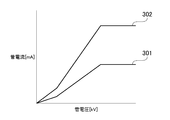
- FIG. 3 is a diagram showing a graphed kV-mA table.
- the horizontal axis of the graph in FIG. 3 indicates the tube voltage (kV), and the vertical axis indicates the tube current (mV).
- lines 301 and 302 in the graph indicate kV-mA tables corresponding to different X-ray doses.
- Lines 301 and 302 are kV-mA tables corresponding to 1 ⁇ Gy and 2 ⁇ Gy, respectively.
- lines 301 and 302 define a set of tube voltage and tube current values such that the lower the transmittance, the higher the value of at least one of tube voltage and tube current.
- the X-ray control unit 122 selects one of the kV-mA tables of the lines 301 and 302 according to the set X-ray dose. Then, the X-ray controller 122 determines the values of the tube voltage and the tube current according to the transmittance of the subject. Thus, the X-ray control unit 122 can set an appropriate irradiation condition according to the thickness of the subject by referring to the kV-mA table.
- the X-ray control unit 122 estimates the transmitted dose based on the image data obtained by the X-ray detection unit 111. Then, the X-ray control unit 122 obtains the transmittance based on the estimated transmitted dose and the X-ray dose applied to the subject, and determines the values of the tube voltage and the tube current based on the transmittance.
- the process for estimating the penetrating dose is not limited to the embodiment.
- the radiation imaging apparatus 100 may estimate the transmitted dose using a device such as an automatic exposure mechanism.
- the noise reduction processing unit 123 reduces the noise of the target image data by synthesizing the target image data to be processed with the image data already obtained in a series of continuous shooting. Specifically, the noise reduction processing unit 123 performs synthesis processing according to an algorithm of recursive filter processing.
- the recursive filter process is a process of combining the target image data (current frame) and already created image data (previous frame) by applying coefficients. By synthesizing a plurality of images in this way, it is possible to remove the noise component.
- the position change is large, the influence of the afterimage due to the synthesis appears strongly.
- the noise reduction processing unit 123 performs recursive filter processing according to (Equation 1).
- T n aS n + (1 -a) T (n-1) ⁇ ( Equation 1)
- T n indicates the current frame after the noise reduction processing.
- Sn represents image data (current frame) obtained by the X-ray detection unit 111, that is, the current frame before noise reduction.
- T (n-1) indicates the immediately preceding frame after the noise reduction processing.
- a indicates a recursive filter coefficient.
- the recursive filter coefficient a represents the composition ratio of the current frame. Therefore, as the coefficient a of the recursive filter is larger, the composition ratio of the current frame is larger and the composition ratio of the previous frame is smaller.
- the noise reduction processing unit 123 determines the value of the recursive filter coefficient a used for the noise reduction processing of the target image data based on the change amount of the relative position specified by the change amount specifying unit 121.
- the noise reduction processing unit 123 determines a recursive filter coefficient “a” that increases as the amount of change increases. That is, the noise reduction processing unit 123 determines a previous frame composition ratio that increases as the amount of change increases (composition ratio determination process).
- the noise reduction processing unit 123 refers to the correspondence table between the change amount and the recursive filter coefficient a, and determines the recursive filter coefficient a based on the change amount.
- the correspondence table is stored in advance in a ROM or the like, for example.
- the noise reduction processing unit 123 determines the first combination ratio for the previous frame, while when the second change amount is specified, the noise reduction processing unit 123 determines the first frame.
- the second synthesis ratio is determined.
- the second change amount is a larger value than the first change amount.
- the second synthesis ratio is a smaller value than the first synthesis ratio.
- the noise reduction processing unit 123 may determine the recursive filter coefficient a using a function for calculating the recursive filter coefficient a from the amount of change. In this case, it is assumed that the function is stored in advance in a ROM, for example.
- FIG. 4 is a flowchart showing imaging processing by the radiation imaging apparatus 100.
- the radiation imaging apparatus 100 obtains a series of continuous image data.
- the X-ray control unit 122 sets initial conditions such as tube voltage, tube current, and irradiation time. It is assumed that initial conditions for each device to be used, a region to be imaged, and a type of examination are stored in advance in a ROM or the like. Then, the X-ray control unit 122 sets initial conditions according to the device to be used.
- step S402 the X-ray generation unit 110 irradiates the subject with X-rays under the irradiation conditions set in step S401 or step S407 described later (irradiation processing).
- step S403 the X-ray detection unit 111 detects the radiation that has passed through the subject, and generates image data based on the detection result (detection process, creation process).
- step S404 the noise reduction processing unit 123 acquires the image data (target image data) generated in step S403 (acquisition processing), and performs noise reduction processing of the target image data (noise reduction processing). Thereby, the image data obtained by the X-ray detection unit 111 is converted into an image suitable for diagnosis and examination.
- step S405 the X-ray control unit 122 confirms whether or not a series of continuous imaging has been completed.
- the X-ray control unit 122 ends the imaging process when the continuous imaging is completed (Yes in step S405).
- the X-ray control unit 122 advances the process to step S406 when the continuous imaging is not completed (No in step S405).
- the change amount specifying unit 121 specifies the change amount of the relative position (change amount specifying process).
- the X-ray control unit 122 sets the X-ray dose based on the amount of change in the relative position (radiation dose setting process), sets the irradiation conditions based on the X-ray dose, and the process proceeds to step S402. Proceed.
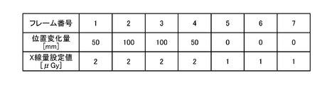
- FIG. 5 is a diagram showing image data (frame) created in the imaging process, the amount of change in relative position, and the X-ray dose setting value.
- the change amount of the relative position is a value specified by the change amount specifying unit 121.
- the X-ray dose setting value is an X-ray dose set by the X-ray control unit 122.
- the example shown in FIG. 5 corresponds to FIG. 2C, and the change amount is equal to or less than the change amount threshold value “0 mm” in the fifth frame.
- the X-ray control unit 122 increases the X-ray dose from “2 ⁇ Gy” to “1 ⁇ Gy” in the fifth frame.
- the irradiation condition of the sixth frame is changed according to the amount of change of the fifth frame. Therefore, the change of the irradiation condition (X dose setting value “1 ⁇ Gy”) is actually applied to the image data of the sixth and subsequent frames.
- the change amount of the relative position is small, that is, when the movement of the visual field becomes small, even if the composition ratio of the frame before the current frame is increased in the recursive filter processing, the image deterioration due to the position shift is small. Furthermore, when the composition ratio of the previous frame is increased, high quality image data can be obtained even if the X-ray dose of the current frame is lowered. When the amount of change is small, high-quality image data can be obtained even if the X-ray dose is lowered due to the visual afterimage effect.
- the X-ray control unit 122 reduces the X-ray dose when the change amount of the relative position is equal to or less than the change amount threshold value. Thereby, it is possible to reduce the exposure amount of the subject while maintaining the quality of the image data created by the radiation imaging apparatus 100.
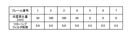
- FIG. 6 is a diagram showing image data (frame) created in the photographing process, a relative position change amount, and a recursive filter coefficient a. 6 corresponds to FIG. 2C, and the change amount of the relative position becomes “0” in the fifth frame. Corresponding to this, the noise reduction processing unit 123 performs the recursive filter coefficient in the fifth frame. Is reduced from “0.8” to “0.5”.
- the noise reduction processing unit 123 decreases the recursive filter coefficient a as the change amount of the relative position is smaller, and increases the composition ratio of the frame before the current frame. Therefore, the noise reduction processing unit 123 can reduce the noise while suppressing the influence of the afterimage.
- the radiation imaging apparatus 100 determines the X-ray dose setting value and the composition ratio of the frame before the current frame in the recursive filter process according to the change amount of the relative position. Thereby, high-quality image data can be obtained while reducing the exposure dose of the patient.
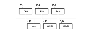
- FIG. 7 is a diagram illustrating a hardware configuration of the control device 120.
- the control device 120 includes a CPU 701, a ROM 702, a RAM 703, an HDD 704, a display unit 705, and an operation unit 706.
- the CPU 701 reads out a control program stored in the ROM 702 and executes various processes.
- the RAM 703 is used as a temporary storage area such as a main memory or work area for the CPU 701.
- the HDD 704 stores image data, various programs, various information described later, and the like.
- the display unit 705 displays various information.
- the operation unit 706 receives various operations from the operator.
- control device 120 The functions of the control device 120 described with reference to FIG. 1 are realized by the CPU 701 reading out a program stored in the ROM 702 or the HDD 704 and executing the program. Similarly, the processing of the control device 120 described with reference to FIG. 4 is realized by the CPU 701 reading a program stored in the ROM 702 or the HDD 704 and executing the program.
- the radiation imaging apparatus 100 may further include a motion detection unit.
- the motion detection unit detects motion based on the image data, and separates the image data into a motion detection region in which motion is detected and a motion non-detection region in which no motion is detected.
- the noise reduction process part 123 combines the spatial filters, such as a recursive filter and a smoothing filter, and performs the process suitable for each area
- region As described above, the noise reduction processing unit 123 can perform more optimized noise reduction processing by performing analysis in accordance with the noise reduction processing algorithm.
- the radiation imaging apparatus 100 changes the sensitivity of the X-ray detection unit 111 or corrects the pixel value for the obtained image data. May be performed. This is because, when the X-ray dose setting value is changed, the X-ray dose reaching the X-ray detection unit 111 is different.
- the radiation imaging apparatus 100 can obtain a constant pixel value regardless of the X-ray dose setting value by changing the sensitivity of the X-ray detection unit 111 or the like. Further, when the tube voltage is changed, the image contrast changes. Therefore, as another example, the radiation imaging apparatus 100 may perform contrast correction on the image data.
- the X-ray control unit 122 adjusts at least one of irradiation time, tube current, and tube voltage according to the fluoroscopic condition one frame before instead of selecting the kV-mA table. (Adjustment process). As a result, the X-ray control unit 122 can change the X-ray dose without changing the kV-mA table.
- FIG. 8 is a diagram showing image data (frame) created in the imaging process, a change in relative position, and an X-ray dose setting value.
- the X-ray control unit 122 increases the X-ray dose from “1 ⁇ Gy” to “2 ⁇ Gy” in the fifth frame (radiation dose changing process). Further, the X-ray control unit 122 reduces the X-ray dose from “2 ⁇ Gy” to “1 ⁇ Gy” in the sixth frame.
- the X-ray control unit 122 changes the irradiation condition at the next irradiation according to the changed X-ray dose.
- the X-ray control unit 122 changes the irradiation conditions of the six frames.
- the X-ray control unit 122 changes the tube voltage, the tube current, the irradiation time, and the like so that the X-ray dose becomes a desired value based on the irradiation condition of the fifth frame.
- FIG. 9 is a diagram showing image data (frame) created in the photographing process, a change in relative position, and a recursive filter coefficient a.
- the noise reduction processing unit 123 increases the recursive filter coefficient a for the first to sixth frames where the X-ray dose setting value is small, and decreases the recursive filter coefficient a for the seventh frame where the X-ray dose setting value is large. Decreasing the recursive filter coefficient a in the seventh frame means increasing the composition ratio in the sixth frame.
- the noise reduction processing unit 123 increases the recursive filter coefficient a again.
- the X-ray control unit 122 temporarily increases the X-ray dose when the change amount of the relative position changes from a value larger than the change amount threshold value to a value equal to or smaller than the change amount threshold value. Change to (second radiation dose).
- the noise reduction processing unit 123 increases the composition ratio of the image data created at the timing when the change amount of the relative position changes from a value larger than the change amount threshold value to a value equal to or smaller than the change amount threshold value. Thereby, the radiation imaging apparatus 100 can reduce noise effectively.
- the X-ray control unit 122 lowers the X-ray dose again after a certain period of time has elapsed after changing the X-ray dose to a large value. Thereby, the radiography apparatus 100 can reduce the exposure dose of the patient.
- the radiation imaging apparatus 100 also determines the X-ray dose setting value to be a low value (1 ⁇ Gy) when the change amount is larger than the change amount threshold as in the first to fifth frames shown in FIG. Thereby, a patient's exposure amount can be reduced.
- the other configuration and processing of the radiation imaging apparatus 100 according to the second embodiment are the same as the configuration and processing of the radiation imaging apparatus 100 according to the first embodiment.
- the radiation imaging apparatus 100 temporarily increases the X-ray dose when the change amount of the relative position becomes small, and reduces noise by using the corresponding image data. Process. Thereby, high-quality image data can be obtained while reducing the exposure dose of the patient.
- the process of reducing the X-ray dose setting value is, for example, an image with an image quality that allows the approximate imaging region to be understood when moving the table on which the patient is placed. This process is suitable for cases where it is sufficient to obtain data.
- the radiation imaging apparatus 100 according to the modification may perform edge-preserving spatial filter processing on image data with a high X-ray dose, and then perform recursive filter processing.
- An image with a high X-ray dose has a high SN ratio. Therefore, the radiation imaging apparatus 100 can perform separation of noise and structure with relatively high accuracy. For this reason, the radiation imaging apparatus 100 can obtain image data in which noise is further suppressed by performing edge preserving spatial filter processing.
- the X-ray control unit 122 stores the image data of the sixth frame obtained corresponding to the high X-ray dose in a ROM or the like as a key frame because the change amount of the relative position becomes small.
- the key frame is an example of reference image data.
- the noise reduction processing unit 123 performs recursive filter processing that synthesizes key frames with respect to the target image data.
- the noise reduction processing unit 123 performs a recursive filter process shown in (Expression 2).
- T n aS n + (1-a) T key (Expression 2)
- T n indicates the current frame after the noise reduction processing.
- Sn represents image data (current frame) obtained by the X-ray detection unit 111, that is, the current frame before noise reduction.
- T key indicates a key image.
- a indicates a recursive filter coefficient.
- FIG. 10 is a diagram showing image data (frame) created in the imaging process, a change in relative position, and an X-ray dose setting value.
- the X-ray control unit 122 increases the X-ray dose in the fifth frame in which the change amount of the relative position is equal to or less than the change amount threshold value.
- the irradiation condition of the image data of the sixth frame is changed.
- the X-ray control unit 122 decreases the X-ray dose in the seventh frame in which the amount of change in the relative position below the change amount threshold value continues.
- the change amount of the relative position is equal to or less than the threshold value
- the X-ray dose may be kept increased while corresponding to a predetermined frame thereafter.
- the X-ray control unit 122 stores the sixth frame imaged with the X-ray dose setting value “2” as a key frame in the memory.
- the noise reduction process part 123 performs the recursive filter process using a key frame with respect to the image data after the 7th frame.
- the recursive filter coefficient is a constant value. Thereby, the amount of noise can be kept constant. It is assumed that the recursive filter coefficient is stored in advance in a ROM or the like.
- the X-ray control unit 122 deletes the key frame from the memory. And the process which synthesize
- the remaining configuration and processing of the radiation imaging apparatus 100 according to the third embodiment are the same as the configuration and processing of the radiation imaging apparatus 100 according to the other embodiments.
- the noise reduction processing unit 123 synthesizes a key frame with less noise, which is captured at a high X-ray dose setting value, with the current frame. Therefore, noise can be effectively reduced.
- the X-ray control unit 122 generates a single key frame by synthesizing a plurality of image data with less noise, and stores the key frame in the memory. May be stored.
- the noise reduction processing unit 123 reduces the key frame composition ratio as time elapses from the key frame creation timing, instead of using a constant value as the recursive filter coefficient. Recursive filter coefficients may be used. As a result, it is possible to prevent displacement between the current frame and the key frame. From the viewpoint of preventing misalignment, and as another example, the noise reduction processing unit 123 corrects the misalignment between the current frame and the key frame as time elapses from the creation timing of the key frame. Key frames may be combined.
- a catheter or the like may be inserted into the patient's body at the timing when the change amount of the relative position becomes equal to or less than the threshold (in FIG. 10, the fifth frame and thereafter).
- the radiation imaging apparatus 100 according to the third modification example separates the image data into an insert region corresponding to the catheter and a non-insert region other than the catheter.
- the radiation imaging apparatus 100 compares the target image data with the pixel values of the image data obtained immediately before, recognizes the line structure, detects motion in the image data (motion detection process), and the like. The separation of the insert region and the non-insert region is performed.
- the noise reduction processing unit 123 performs recursive filter processing using different recursive filter coefficients for the insert region and the non-insert region. Specifically, the noise reduction processing unit 123 performs a recursive filter process using a small recursive filter coefficient on a non-insert region having a small change in image data.
- the noise reduction processing unit 123 performs recursive filter processing using a recursive filter coefficient larger than the recursive filter coefficient of the non-insert region for the insert region having a large change in the image data. Thereby, the visibility of the catheter in image data can be improved.
- the X-ray control unit 122 when the state in which the amount of change in the relative position is small continues, the X-ray control unit 122 The X-ray dose will be increased again. Then, the X-ray control unit 122 replaces the image data created corresponding to the high X-ray dose with a key frame already stored. Thereby, the position shift according to time passage can be prevented.
- the imaging process by the radiation imaging apparatus 100 according to the present embodiment may be selectively executed.
- the imaging process according to the present embodiment is not suitable for imaging an area where motion is constantly detected, such as the heart. Therefore, the imaging process according to the present embodiment may be executed only when imaging a predetermined part.
- the shooting process according to the present embodiment may be executed when a predetermined shooting condition is selected.
- the present invention can also be realized by executing the following processing. That is, software (program) that realizes the functions of the above-described embodiments is supplied to a system or apparatus via a network or various storage media. Then, the computer (or CPU, MPU, etc.) of the system or apparatus reads and executes the program.
- high-quality image data can be obtained while reducing the exposure dose of the patient.
Landscapes
- Life Sciences & Earth Sciences (AREA)
- Health & Medical Sciences (AREA)
- Engineering & Computer Science (AREA)
- Medical Informatics (AREA)
- Pathology (AREA)
- Heart & Thoracic Surgery (AREA)
- High Energy & Nuclear Physics (AREA)
- Physics & Mathematics (AREA)
- Nuclear Medicine, Radiotherapy & Molecular Imaging (AREA)
- Optics & Photonics (AREA)
- Veterinary Medicine (AREA)
- Radiology & Medical Imaging (AREA)
- Biomedical Technology (AREA)
- Biophysics (AREA)
- Molecular Biology (AREA)
- Surgery (AREA)
- Animal Behavior & Ethology (AREA)
- General Health & Medical Sciences (AREA)
- Public Health (AREA)
- Computer Vision & Pattern Recognition (AREA)
- Apparatus For Radiation Diagnosis (AREA)
Abstract
検知手段により、被写体を透過した放射線の検知結果に基づいて作成された複数の画像データのうち、対象画像データの直前に作成された直前画像データの作成タイミングから、対象画像データの作成タイミングまでの間の、被写体の検知手段に対する相対位置の変化量を特定する変化量特定手段と、変化量に基づいて、照射手段が照射する放射線量を設定する放射線量設定手段と、変化量に基づいて、合成比率を決定する合成比率決定手段と、対象画像データに、対象画像データよりも前に作成された画像データを、合成比率に応じて合成することにより、対象画像データのノイズを低減するノイズ低減手段とを有する。
Description
本明細書の開示は、放射線撮影の制御装置、制御方法及びプログラムに関する。
透視装置は一般撮影と異なり、検査だけでなく、透視画像を見ながら血管内治療等を行うIVRという手技にも用いられている。このような手技を行う際、手技の困難さ等に応じて透視時間が長くなり、患者の被ばく線量増大を招く場合がある。このような患者の被ばく線量を低減するための技術として、例えば特許文献1には、テーブルの動き等に応じてパルス占有率を変更する事で被ばく線量を低減する技術が開示されている。また、特許文献2には、通常の線量と通常の線量よりも低線量となる照射を組み合わせた照射パターンを繰り返す技術が開示されている。
しかしながら、パルス占有率を低くした場合には、動きの滑らかさが不足することがあり、また、放射線量を低くした場合には、ノイズ量が増加することがあるという問題があった。
そこで本発明の実施形態に係る制御装置は、検知手段により、被写体を透過した放射線の検知結果に基づいて作成された複数の画像データのうち、対象画像データの直前に作成された直前画像データの作成タイミングから、前記対象画像データの作成タイミングまでの間の、前記被写体の前記検知手段に対する相対位置の変化量を特定する変化量特定手段と、前記変化量に基づいて、照射手段が照射する放射線量を設定する放射線量設定手段と、前記変化量に基づいて、合成比率を決定する合成比率決定手段と、前記対象画像データに、前記対象画像データよりも前に作成された画像データを、前記合成比率に応じて合成することにより、前記対象画像データのノイズを低減するノイズ低減手段とを有する。
これにより、患者の被ばく量を低減しつつ、高品質な画像データを得ることができる。
以下、本発明の実施形態について図面に基づいて説明する。
(第1の実施形態)
図1は、第1の実施形態に係る放射線撮影装置100を示す図である。放射線撮影装置100は、X線発生部110と、X線検知部111と、制御装置120とを有している。制御装置120は、変化量特定部121と、X線制御部122と、ノイズ低減処理部123とを有している。
図1は、第1の実施形態に係る放射線撮影装置100を示す図である。放射線撮影装置100は、X線発生部110と、X線検知部111と、制御装置120とを有している。制御装置120は、変化量特定部121と、X線制御部122と、ノイズ低減処理部123とを有している。
X線発生部110は、被写体としての患者に向けて、X線(放射線)を放射する。そして、X線検知部111は、患者を透過したX線を検知し、検知したX線に基づいて、画像データを生成する。X線検知部111は、連続してX線の検知及び画像データの作成を行い、複数の画像データを得る。
本実施形態にかかる放射線撮影装置100は、被写体としての患者に対するX線検知部111の相対位置を変化させることができる。具体的には、放射線撮影装置100には、X線検知部111又は患者を載せるテーブル(不図示)のうち少なくとも一方が、移動可能に設けられている。
そして、X線検知部111が放射線の検知及び画像データの作成を行う度に、不図示の制御部が、X線検知部111又はテーブルを移動させる。これにより、放射線撮影装置100は、適宜、相対位置を変化させることができる。なお、X線発生部110は、制御部の制御の下、X線検知部111の移動に対応して移動するものとする。
変化量特定部121は、画像データが作成される度に、直前画像データの作成タイミングから対象画像データの作成タイミングまでの間の相対位置の変化量を特定する。ここで、対象画像データとは、処理対象の画像データであり、直前画像データは、対象画像データの直前に作成された画像データである。なお、変化量特定部121は、例えば、被写体が載せられたテーブル、X線検知部111の保持具、放射線管球支持支柱、コリメータ等の動きに基づいて、相対位置の変化量を特定するものとする。
他の例としては、変化量特定部121は、X線検知部111により作成された画像データの解析結果に基づいて、相対位置の変化量を特定してもよい。画像データの解析結果に基づく、相対位置の変化量の特定方法については、例えば、特開2008-220414号公報を参照することができる。
図2は、相対位置を変化させる処理を説明するための図である。被写体Aに対するX線検知部111の相対位置が、図2(a)に示す位置201から図2(b)に示す位置202まで、矢印Bの方向に沿って変化し、位置202において、相対位置が固定された状態、すなわち視野が固定された状態となるものとする。これに対応し、相対位置が、位置201から位置202までの変化する間、X線検知部111は、適宜画像データの撮影を行い、相対位置が位置202に固定された後も、定期的に画像データの撮影を行うこととする。
図2(c)は、図2(a),(b)に示す相対位置の変化に対応して得られた画像データの一例を示す図である。フレーム番号1の画像データは、図2(a)の位置201において放射されたX線に対応する画像データである。フレーム番号2~フレーム番号4の画像データは、相対位置が矢印Bの方向に沿って変化している期間に放射されたX線に対応する画像データである。フレーム番号4の画像データは、図2(b)の位置202において放射されたX線に対応する画像データである。フレーム番号5~7の画像データは、相対位置が固定された状態において順次作成された画像データである。
このように、放射線撮影装置100は、相対位置を変化させながら、一定時間毎に連続して画像データを作成することができる。さらに、放射線撮影装置100は、相対位置を固定した状態で、一定時間毎に連続して画像データを作成することができる。なお、画像データの作成間隔、すなわち撮影間隔は、任意である。撮影間隔はまた、一定でなくともよい。
X線制御部122は、変化量特定部121により特定された相対位置の変化量に基づいて、X線量を設定する。そして、X線制御部122は、設定されたX線量に基づいて、管電圧、管電流、照射時間等の照射条件を設定する。X線制御部122により設定されるX線量は、被写体を透過した後のX線量の目標値である。
まず、相対位置の変化量に基づいて、X線量を設定する処理について説明する。X線制御部122は、変化量が変化量閾値以下である場合に、X線量を1μGy(第1のX線量)に設定し、変化量が変化量閾値よりも大きい場合には、X線量を2μGy(第2のX線量)に設定する。ここで、変化量閾値は、後述のROM等に予め格納されているものとする。なお、本実施形態においては、変化量閾値は「0mm」に設定されているものとする。
すなわち、X線制御部122は、第1の変化量が特定された場合に、第1のX線量を設定する一方で、第2の変化量が特定された場合には、第2のX線量を設定する。ここで、第2の変化量は、第1の変化量に比べて大きい値である。第2のX線量は、第1のX線量に比べて大きい値である。
なお、本実施形態においては、X線制御部122は、変化量「0mm」を変化閾値とし、変化量閾値「0mm」以下の場合に、X線量を2μGyから1μGyに下げることとしたが、変化量閾値は、「0mm」に限定されるものではなく、他の値であってもよい。
次に、照射条件を設定する処理について説明する。なお、X線量を設定する処理については後述する。X線制御部122は、X線量に基づいて、kV-mAテーブルを参照して、管電圧及び管電流を決定する。ここで、kV-mAテーブルは、被写体の透過率と、透過率に対応した管電圧及び管電流を、X線量毎に定めた情報である。kV-mAテーブルは、例えばROM等に予め設定されているものとする。
図3は、グラフ化したkV-mAテーブルを示す図である。図3のグラフの横軸は、管電圧(kV)、縦軸は、管電流(mV)を示している。また、グラフ中の線301,302はそれぞれ、異なるX線量に応じたkV-mAテーブルを示している。線301,302は、それぞれ1μGy,2μGyに対応するkV-mAテーブルである。
被写体が厚くなる程、放射線は被写体を透過し難くなる。これに対応し、線301,302は、透過率が低くなる程、管電圧及び管電流のうち少なくとも一方の値がより高くなるような管電圧と管電流の値の組を定めている。
X線制御部122は、設定されたX線量に応じて、線301,302のkV-mAテーブルのうちいずれかのkV-mAテーブルを選択する。そして、X線制御部122は、被写体の透過率に応じて、管電圧及び管電流の値を決定する。このように、X線制御部122は、kV-mAテーブルを参照することにより、被写体の厚さに応じた適切な照射条件を設定することができる。
なお、X線制御部122は、X線検知部111により得られた画像データに基づいて、透過線量を推定する。そして、X線制御部122は、推定した透過線量と被写体に照射したX線量とに基づいて、透過率を求め、透過率に基づいて、管電圧及び管電流の値を決定するものとする。
なお、透過線量を推定する処理は、実施形態に限定されるものではない。他の例としては、放射線撮影装置100は、自動露出機構等の装置を利用して透過線量を推定することとしてもよい。
図1に戻り、ノイズ低減処理部123は、処理対象とする対象画像データに対し、一連の連続撮影において既に得られている画像データを合成することにより、対象画像データのノイズを低減する。具体的には、ノイズ低減処理部123は、リカーシブフィルタ処理のアルゴリズムに従い、合成処理を行う。リカーシブフィルタ処理とは、対象画像データ(現フレーム)と、既に作成済みの画像データ(前フレーム)に各々係数をかけて合成する処理である。このように複数の画像を合成することによって、ノイズ成分を除去する事が可能となる一方、位置変化が大きい場合は合成による残像の影響が強く出現する。
ノイズ低減処理部123は、(式1)によりリカーシブフィルタ処理を行う。
Tn=aSn+(1-a)T(n-1) ・・・(式1)
Tn=aSn+(1-a)T(n-1) ・・・(式1)
ここで、Tnは、ノイズ低減処理後の現フレームを示している。Snは、X線検知部111により得られた画像データ(現フレーム)、すなわちノイズ低減前の現フレームを示している。T(n-1)は、ノイズ低減処理後の直前フレームを示している。また、aは、リカーシブフィルタ係数を示している。
リカーシブフィルタ係数aは、現フレームの合成比率を表す。したがって、リカーシブフィルタの係数aが大きいほど現フレームの合成比率が大きく、前フレームの合成比率が小さくなる。
ノイズ低減処理部123は、変化量特定部121により特定された、相対位置の変化量に基づいて、対象画像データのノイズ低減処理に利用するリカーシブフィルタ係数aの値を決定する。ノイズ低減処理部123は、変化量が大きい程大きい値となるようなリカーシブフィルタ係数aを決定する。すなわち、ノイズ低減処理部123は、変化量が大きい程、大きくなるような前フレームの合成比率を決定する(合成比率決定処理)。
ノイズ低減処理部123は、具体的には、変化量とリカーシブフィルタ係数aの対応テーブルを参照し、変化量に基づいて、リカーシブフィルタ係数aを決定する。ここで、対応テーブルは、例えばROM等に予め格納されているものとする。
すなわち、ノイズ低減処理部123は、第1の変化量が特定された場合に、前フレームに対し第1の合成比率を決定する一方、第2の変化量が特定された場合には、前フレームに対し、第2の合成比率を決定する。ここで、第2の変化量は、第1の変化量に比べて大きい値である。第2の合成比率は、第1の合成比率に比べて小さい値である。
他の例としては、ノイズ低減処理部123は、変化量からリカーシブフィルタ係数aを算出する関数を利用して、リカーシブフィルタ係数aを決定してもよい。この場合、関数は、例えばROM等に予め格納されているものとする。
図4は、放射線撮影装置100による撮影処理を示すフローチャートである。撮影処理において、放射線撮影装置100は、連続する一連の画像データを得る。ステップS401において、X線制御部122は、管電圧、管電流、照射時間等の初期条件を設定する。使用する装置、撮影する部位や検査の種類毎の初期条件は、ROM等に予め格納されているものとする。そして、X線制御部122は、使用する装置等に応じた初期条件を設定する。
ステップS402において、X線発生部110は、ステップS401又は後述のステップS407において設定された照射条件にてX線を被写体に向けて照射する(照射処理)。次に、ステップS403において、X線検知部111は、被写体を透過した放射線を検知し、検知結果に基づいて、画像データを生成する(検知処理、作成処理)。
次に、ステップS404において、ノイズ低減処理部123は、ステップS403において生成された画像データ(対象画像データ)を取得し(取得処理)、対象画像データのノイズ低減処理を行う(ノイズ低減処理)。これにより、X線検知部111により得られた画像データは、診断や検査に適した画像に変換される。
次に、ステップS405において、X線制御部122は、一連の連続撮影が終了したか否かを確認する。X線制御部122は、連続撮影が終了した場合には(ステップS405でYes)、撮影処理を終了する。
X線制御部122は、連続撮影が終了していない場合には(ステップS405でNo)、処理をステップS406へ進める。ステップS406において、変化量特定部121は、相対位置の変化量を特定する(変化量特定処理)。次に、ステップS407において、X線制御部122は、相対位置の変化量に基づいて、X線量を設定し(放射線量設定処理)、X線量に基づき照射条件を設定し、処理をステップS402へ進める。
図5は、撮影処理において作成された画像データ(フレーム)と、相対位置の変化量と、X線量設定値とを示す図である。相対位置の変化量は、変化量特定部121により特定された値である。X線量設定値は、X線制御部122により設定されたX線量である。図5に示す例は、図2(c)に対応し、5フレーム目において、変化量が変化量閾値「0mm」以下になっている。そして、これに対応し、X線制御部122は、5フレーム目において、X線量を「2μGy」から「1μGy」に上げている。
なお、本実施形態においては、5フレーム目の変化量に応じて、6フレーム目の照射条件を変更する。したがって、実際に照射条件の変更(X線量設定値「1μGy」)が適用されるのは、6フレーム目以降の画像データとなる。
相対位置の変化量が小さい場合、すなわち視野の動きが小さくなった場合には、リカーシブフィルタ処理において、現フレームよりも前のフレームの合成比率を大きくしても、位置ずれによる画像劣化は少ない。さらに、前のフレームの合成比率を大きくする場合には、現フレームのX線量を下げても高品質な画像データを得ることができる。また、変化量が小さい場合には、視覚の残像効果により、X線量を下げても高品質な画像データを得ることができる。
以上のことから、X線制御部122は、相対位置の変化量が変化量閾値以下となった場合には、X線量を下げることとした。これにより、放射線撮影装置100により作成される画像データの品質を維持しつつ、被写体の被ばく量を低減することができる。
図6は、撮影処理において作成された画像データ(フレーム)と、相対位置の変化量と、リカーシブフィルタ係数aとを示す図である。図6は、図2(c)に対応し、5フレーム目において、相対位置の変化量が「0」になり、これに対応し、ノイズ低減処理部123は、5フレーム目において、リカーシブフィルタ係数を「0.8」から「0.5」に減少させている。
このように、ノイズ低減処理部123は、相対位置の変化量が小さい程、リカーシブフィルタ係数aを下げ、現フレームよりも前のフレームの合成比率を大きくする。したがって、ノイズ低減処理部123は、残像の影響を抑えつつ、ノイズを低減することができる。
以上のように、本実施形態にかかる放射線撮影装置100は、相対位置の変化量に応じて、X線量設定値及びリカーシブフィルタ処理における現フレームより前のフレームの合成比率を決定する。これにより、患者の被ばく量を低減しつつ、高品質な画像データを得ることができる。
図7は、制御装置120のハードウェア構成を示す図である。制御装置120は、CPU701と、ROM702と、RAM703と、HDD704と、表示部705と、操作部706とを有している。CPU701は、ROM702に記憶された制御プログラムを読み出して各種処理を実行する。RAM703は、CPU701の主メモリ、ワークエリア等の一時記憶領域として用いられる。HDD704は、画像データや各種プログラム、後述する各種情報等を記憶する。表示部705は、各種情報を表示する。操作部706は、操作者からの各種操作を受け付ける。
図1を参照しつつ説明した制御装置120の機能は、CPU701がROM702又はHDD704に格納されているプログラムを読み出し、このプログラムを実行することにより実現されるものである。同様に、図4を参照しつつ説明する制御装置120の処理は、CPU701がROM702又はHDD704に格納されているプログラムを読み出し、このプログラムを実行することにより実現されるものである。
次に、本実施形態にかかる放射線撮影装置100の第1の変更例について説明する。第1の変更例としては、放射線撮影装置100は、動き検出部をさらに有してもよい。動き検出部は、画像データに基づいて動きを検出し、画像データを、動きが検出された動き検出領域と、動きが検出されなかった動き非検出領域とに分離する。そして、ノイズ低減処理部123は、リカーシブフィルタと平滑化フィルタ等の空間フィルタを組み合わせて、領域それぞれに適した処理を領域単位で行う。このように、ノイズ低減処理部123は、ノイズ低減処理のアルゴリズムに合わせた解析を行うことにより、より最適化されたノイズ低減処理を行うことができる。
第2の変更例としては、X線制御部122によりX線量が変更された場合には、放射線撮影装置100は、X線検知部111の感度の変更や、得られた画像データに対する画素値補正を行ってもよい。X線量設定値が変更された場合には、X線検知部111に到達するX線量が異なるためである。放射線撮影装置100は、X線検知部111の感度変更等を行うことにより、X線量設定値によらず一定の画素値を得ることができる。また、管電圧が変更された場合には、画像コントラストが変化する。そこで、他の例としては、放射線撮影装置100は、画像データに対し、コントラストの補正を行ってもよい。
第3の変更例としては、X線制御部122は、kV-mAテーブルを選択するのに替えて、照射時間、管電流、管電圧の少なくとも一つを1フレーム前の透視条件に応じて調整することとしてもよい(調整処理)。これにより、X線制御部122は、kV-mAテーブルを変更することなく、X線量を変更することができる。
(第2の実施形態)
次に、第2の実施形態にかかる放射線撮影装置100について説明する。ここでは、第2の実施形態にかかる放射線撮影装置100について、第1の実施形態にかかる放射線撮影装置100と異なる部分について説明する。
次に、第2の実施形態にかかる放射線撮影装置100について説明する。ここでは、第2の実施形態にかかる放射線撮影装置100について、第1の実施形態にかかる放射線撮影装置100と異なる部分について説明する。
図8は、撮影処理において作成された画像データ(フレーム)と、相対位置の変化量と、X線量設定値とを示す図である。第2の実施形態においては、X線制御部122は、5フレーム目において、X線量を「1μGy」から「2μGy」に上げている(放射線量変更処理)。さらに、X線制御部122は、6フレーム目において、X線量を「2μGy」から「1μGy」に下げている。
X線制御部122は、変更したX線量に応じて、次の照射時の照射条件を変更する。5フレーム目でX線量設定値を変更した場合、X線制御部122は、6フレームの照射条件を変更する。図8に示す例において、X線制御部122は、5フレーム目の照射条件に基づいて、X線量が所望の値になるように管電圧、管電流、照射時間等を変更する。
図9は、撮影処理において作成された画像データ(フレーム)と、相対位置の変化量と、リカーシブフィルタ係数aとを示す図である。ノイズ低減処理部123は、X線量設定値が小さい1~6フレーム目に対し、リカーシブフィルタ係数aを大きくし、X線量設定値が大きい7フレーム目において、リカーシブフィルタ係数aを下げている。7フレーム目のリカーシブフィルタ係数aを下げることは、6フレーム目の合成比率を上げることを意味している。
なお、7フレームに続く8フレーム以降において、相対位置の変化量が再び増加した場合には、ノイズ低減処理部123は、再びリカーシブフィルタ係数aを上げることとする。
すなわち、本実施形態においては、X線制御部122は、相対位置の変化量が変化量閾値よりも大きい値から、変化量閾値以下の値に変化した場合に、X線量を一時的に大きい値(第2の放射線量)に変更する。
そして、ノイズ低減処理部123は、相対位置の変化量が変化量閾値よりも大きい値から、変化量閾値以下の値に変化したタイミングにおいて作成された画像データの合成比率を高くする。これにより、放射線撮影装置100は、ノイズを効果的に低減することができる。
さらに、X線制御部122は、X線量を大きい値に変更してから一定期間が経過すると、再びX線量を下げる。これにより、放射線撮影装置100は、患者の被ばく量を低減することができる。放射線撮影装置100はまた、図7に示す1~5フレーム目のように、変化量が変化量閾値よりも大きい場合には、X線量設定値を低い値(1μGy)に決定する。これにより、患者の被ばく量を低減することができる。
なお、第2の実施形態にかかる放射線撮影装置100のこれ以外の構成及び処理は、第1の実施形態にかかる放射線撮影装置100の構成及び処理と同様である。
以上のように、第2の実施形態にかかる放射線撮影装置100は、相対位置の変化量が小さくなった場合に、一時的にX線量を上げ、これに対応する画像データを利用してノイズ低減処理を行う。これにより、患者の被ばく量を低減しつつ、高品質な画像データを得ることができる。
このように、相対位置の変化量が変化量閾値よりも大きい場合に、X線量設定値を小さくする処理は、例えば、患者を載せたテーブル移動時には、おおよその撮影部位がわかる程度の画質の画像データが得られればよいような場合に適した処理である。
第2の実施形態にかかる放射線撮影装置100の変更例について説明する。変更例にかかる放射線撮影装置100は、X線量の高い画像データに対しては、エッジ保存型空間フィルタ処理を行い、その後リカーシブフィルタ処理を行っても良い。X線量が高い画像は、SN比が高い。したがって、放射線撮影装置100は、ノイズと構造の分離を比較的精度よく行うことができる。このため、放射線撮影装置100は、エッジ保存型空間フィルタ処理を行うことにより、よりノイズの抑制された画像データを得ることができる。
(第3の実施形態)
次に、第3の実施形態にかかる放射線撮影装置100について説明する。ここでは、第3の実施形態にかかる放射線撮影装置100について、他の実施形態にかかる放射線撮影装置100と異なる部分について説明する。第3の実施形態にかかるX線制御部122は、相対位置の変化量が小さくなり、高いX線量に対応して得られた6フレーム目の画像データをキーフレームとしてROM等に格納する。ここで、キーフレームは、参照画像データの一例である。そして、ノイズ低減処理部123は、対象画像データに対し、キーフレームを合成するようなリカーシブフィルタ処理を行う。
次に、第3の実施形態にかかる放射線撮影装置100について説明する。ここでは、第3の実施形態にかかる放射線撮影装置100について、他の実施形態にかかる放射線撮影装置100と異なる部分について説明する。第3の実施形態にかかるX線制御部122は、相対位置の変化量が小さくなり、高いX線量に対応して得られた6フレーム目の画像データをキーフレームとしてROM等に格納する。ここで、キーフレームは、参照画像データの一例である。そして、ノイズ低減処理部123は、対象画像データに対し、キーフレームを合成するようなリカーシブフィルタ処理を行う。
具体的には、ノイズ低減処理部123は、(式2)に示すリカーシブフィルタ処理を行う。
Tn=aSn+(1-a)Tkey ・・・(式2)
Tn=aSn+(1-a)Tkey ・・・(式2)
ここで、Tnは、ノイズ低減処理後の現フレームを示している。Snは、X線検知部111により得られた画像データ(現フレーム)、すなわちノイズ低減前の現フレームを示している。Tkeyは、キー画像を示している。また、aは、リカーシブフィルタ係数を示している。
図10は、撮影処理において作成された画像データ(フレーム)と、相対位置の変化量と、X線量設定値とを示す図である。図10に示すように、X線制御部122は、相対位置の変化量が変化量閾値以下となった、5フレーム目において、X線量を上げる。これに対応し、6フレーム目の画像データの照射条件が変更される。
さらに、X線制御部122は、6フレーム目のX線量を上げた後、変化量閾値以下の相対位置の変化量が継続する7フレーム目において、X線量を下げる。なお、他の例としては、相対位置の変化量が閾値以下となった場合に、その後予め定められたフレームに対応する間、X線量を上げたままとしてもよい。
X線制御部122は、X線量設定値「2」で撮影された6フレーム目を、キーフレームとしてメモリに格納する。そして、ノイズ低減処理部123は、7フレーム目以降の画像データに対し、キーフレームを用いたリカーシブフィルタ処理を行う。なお、本実施形態においては、リカーシブフィルタ係数は一定値であるものとする。これにより、ノイズ量を一定に保つことができる。リカーシブフィルタ係数は、予めROM等に格納されているものとする。
なお、再び相対位置の変化量が変化量閾値よりも大きくなった場合には、X線制御部122は、メモリからキーフレームを削除する。そして、作成された画像データに対しては、既に得られた画像データを合成する処理は行わないこととする。
なお、第3の実施形態にかかる放射線撮影装置100のこれ以外の構成及び処理は、他の実施形態にかかる放射線撮影装置100の構成及び処理と同様である。
なお、第3の実施形態にかかる放射線撮影装置100のこれ以外の構成及び処理は、他の実施形態にかかる放射線撮影装置100の構成及び処理と同様である。
このように、第3の実施形態においては、ノイズ低減処理部123は、高いX線量設定値において撮影された、ノイズの少ないキーフレームを現フレームに合成する。したがって、ノイズを効果的に低減することができる。
第3の実施形態にかかる放射線撮影装置100の第1の変更例としては、X線制御部122は、ノイズの少ない複数の画像データを合成して、1のキーフレームを作成し、これをメモリに格納してもよい。
第2の変更例としては、ノイズ低減処理部123は、リカーシブフィルタ係数として一定値を利用するのに替えて、キーフレームの作成タイミングからの時間経過に応じて、キーフレームの合成比率を下げるようなリカーシブフィルタ係数を利用してもよい。これにより、現フレームとキーフレームの間の位置ずれを防ぐことができる。
位置ずれを防ぐ観点から、また他の例としては、ノイズ低減処理部123は、キーフレームの作成タイミングからの時間経過に応じて、現フレームとキーフレームの位置ずれを補正しつつ、現フレームにキーフレームを合成してもよい。
位置ずれを防ぐ観点から、また他の例としては、ノイズ低減処理部123は、キーフレームの作成タイミングからの時間経過に応じて、現フレームとキーフレームの位置ずれを補正しつつ、現フレームにキーフレームを合成してもよい。
次に、第3の変更例について説明する。放射線撮影装置100は、相対位置の変化量が閾値以下となったタイミング(図10においては、5フレーム目以降)において、患者の体内にカテーテル等が挿入される場合がある。第3の変更例にかかる放射線撮影装置100は、カテーテル等が挿入された場合に、画像データをカテーテルに対応する挿入物領域と、カテーテル以外の非挿入物領域とに分離する。
放射線撮影装置100は、具体的には、対象画像データと、その直前に得られた画像データの画素値の比較、線上構造の認識処理、画像データ内の動き検出(動き検出処理)、等により、挿入物領域と非挿入物領域の分離を行う。
そして、ノイズ低減処理部123は、挿入物領域と非挿入物領域に対し、異なるリカーシブフィルタ係数を利用したリカーシブフィルタ処理を行う。具体的には、ノイズ低減処理部123は、画像データ内の変化の小さい非挿入物領域に対し、小さいリカーシブフィルタ係数を用いたリカーシブフィルタ処理を行う。
一方、ノイズ低減処理部123は、画像データ内の変化の大きい挿入物領域に対しては、非挿入物領域のリカーシブフィルタ係数に比べて大きいリカーシブフィルタ係数を用いたリカーシブフィルタ処理を行う。これにより、画像データにおけるカテーテルの視認性を向上することができる。
第4の変更例としては、相対位置の変化量が小さい状態が継続する場合には、一定時間が経過する度に、又は一定フレーム数の作成が完了する度に、X線制御部122は、再度X線量を上げることとする。そして、X線制御部122は、高いX線量に対応して作成された画像データを既に格納されているキーフレームと入れ替える。これにより、時間経過に応じた位置ずれを防ぐことができる。
なお、本実施形態にかかる放射線撮影装置100による撮影処理は、選択的に実行されてもよい。本実施形態にかかる撮影処理は、例えば心臓のように、定常的に動きが検出される部位のへの撮影には適さない。そこで、所定の部位の撮影時においてのみ、本実施形態にかかる撮影処理が実行されるものとしてもよい。また、他の例としては、本実施形態にかかる撮影処理は、所定の撮影条件が選択された場合に実行されるものとしてもよい。
<その他の実施形態>
また、本発明は、以下の処理を実行することによっても実現される。即ち、上述した実施形態の機能を実現するソフトウェア(プログラム)を、ネットワーク又は各種記憶媒体を介してシステム或いは装置に供給する。そして、そのシステム或いは装置のコンピュータ(又はCPUやMPU等)がプログラムを読み出して実行する処理である。
また、本発明は、以下の処理を実行することによっても実現される。即ち、上述した実施形態の機能を実現するソフトウェア(プログラム)を、ネットワーク又は各種記憶媒体を介してシステム或いは装置に供給する。そして、そのシステム或いは装置のコンピュータ(又はCPUやMPU等)がプログラムを読み出して実行する処理である。
以上、上述した各実施形態によれば、患者の被ばく量を低減しつつ、高品質な画像データを得ることができる。
以上、本発明の好ましい実施形態について詳述したが、本発明は係る特定の実施形態に限定されるものではなく、特許請求の範囲に記載された本発明の要旨の範囲内において、種々の変形・変更が可能である。
本願は、2013年11月08日提出の日本国特許出願特願2013-232310を基礎として優先権を主張するものであり、その記載内容の全てをここに援用する。
100 放射線撮影装置
110 X線発生部
111 X線検知部
120 制御装置
121 変化量特定部
122 X線制御部
123 ノイズ低減部
110 X線発生部
111 X線検知部
120 制御装置
121 変化量特定部
122 X線制御部
123 ノイズ低減部
Claims (14)
- 検知手段により、被写体を透過した放射線の検知結果に基づいて作成された複数の画像データのうち、対象画像データの直前に作成された直前画像データの作成タイミングから、前記対象画像データの作成タイミングまでの間の、前記被写体の前記検知手段に対する相対位置の変化量を特定する変化量特定手段と、
前記変化量に基づいて、照射手段が照射する放射線量を設定する放射線量設定手段と、前記変化量に基づいて、合成比率を決定する合成比率決定手段と、
前記対象画像データに、前記対象画像データよりも前に作成された画像データを、前記合成比率に応じて合成することにより、前記対象画像データのノイズを低減するノイズ低減手段と
を有する制御装置。 - 前記放射線量設定手段は、第1の変化量が特定された場合に、第1の放射線量を設定し、前記第1の変化量に比べて大きい第2の変化量が特定された場合に、前記第1の放射線量に比べて大きい第2の放射線量を設定し、
前記合成比率決定手段は、前記第1の変化量が特定された場合に、第1の合成比率を決定し、前記第2の変化量が特定された場合に、前記第1の合成比率に比べて小さい第2の合成比率を決定する請求項1に記載の制御装置。 - 前記合成比率決定手段は、前記変化量が大きくなるにつれて小さくなる前記合成比率を決定する請求項2に記載の制御装置。
- 前記放射線量設定手段は、前記変化量が変化量閾値以下の値の場合に、前記第1の放射線量を設定し、前記変化量が変化量閾値よりも大きい場合に、前記第2の放射線量を設定する請求項2に記載の制御装置。
- 前記放射線量設定手段は、前記変化量が変化量閾値よりも大きい場合に、第1の放射線量を設定し、前記変化量が前記変化量閾値よりも大きい値から変化量閾値以下の値に変化した場合に、前記第1の放射線量に比べて大きい第2の放射線量を設定し、前記第2の放射線量を設定してから一定期間が経過すると、前記第1の放射線量に設定し、
前記合成比率決定手段は、前記変化量が前記変化量閾値よりも大きい値から変化量閾値以下の値に変化したタイミングにおいて、前記第2の放射線量の照射に対応して作成された画像データの合成比率を、前記第2の放射線量の照射に対応する画像データよりも前に作成された画像データの合成比率に比べて高い値に決定する請求項1に記載の制御装置。 - 検知手段により、被写体を透過した放射線の検知結果に基づいて作成された複数の画像データのうち、対象画像データの直前に作成された直前画像データの作成タイミングから、前記対象画像データの作成タイミングまでの間の、前記被写体と前記検知手段との相対位置の変化量を特定する変化量特定手段と、
前記変化量が変化量閾値よりも大きい値から変化量閾値以下の値に変化した場合に、照射手段が照射する放射線量を第1の放射線量から前記第1の放射線量に比べて大きい第2の放射線量に変更する放射線量変更手段と、
前記第2の放射線量の照射に対応して作成された画像データを参照画像データとして、前記対象画像データに合成することにより、前記対象画像データのノイズを低減するノイズ低減手段と
を有する制御装置。 - 前記対象画像データに基づいて、動きを検出する動き検出手段をさらに有し、
前記ノイズ低減手段は、前記対象画像データのうち動きが検出された検出領域に対し、前記対象画像データのうち動きが検出されなかった非検出領域への前記参照画像データの合成比率に比べて低い合成比率で、前記参照画像データを合成することにより、前記対象画像データのノイズを低減する請求項6に記載の制御装置。 - 前記ノイズ低減手段は、リカーシブフィルタ処理により、前記対象画像データのノイズを低減する請求項1乃至7何れか1項に記載の制御装置。
- 前記放射線量に基づいて、管電圧、管電流及び照射時間のうち少なくとも1つの値を調整する調整手段をさらに有する請求項1乃至8何れか1項に記載の制御装置。
- 請求項1乃至9何れか1項に記載の制御装置と、
放射線を照射する照射手段と、
前記被写体を透過した放射線を連続して検知し、検知結果に基づいて、複数の画像データを作成する作成手段と
を有する撮影装置。 - 制御装置が実行する制御方法であって、
検知手段により、被写体を透過した放射線の検知結果に基づいて作成された複数の画像データのうち、対象画像データの直前に作成された直前画像データの作成タイミングから、前記対象画像データの作成タイミングまでの間の、前記被写体の前記検知手段に対する相対位置の変化量を特定する変化量特定ステップと、
前記変化量に基づいて、放射線量を設定する放射線量設定ステップと、
前記変化量に基づいて、合成比率を決定する合成比率決定ステップと、
前記対象画像データに、前記対象画像データよりも前に作成された画像データを、前記合成比率に応じて合成することにより、前記対象画像データのノイズを低減するノイズ低減ステップと
を含む制御方法。 - 制御装置が実行する制御方法であって、
検知手段により、被写体を透過した放射線の検知結果に基づいて作成された複数の画像データのうち、対象画像データの直前に作成された直前画像データの作成タイミングから、前記対象画像データの作成タイミングまでの間の、前記被写体と前記検知手段との相対位置の変化量を特定する変化量特定ステップと、
前記変化量が変化量閾値よりも大きい値から変化量閾値以下の値に変化した場合に、放射線量を第1の放射線量から前記第1の放射線量に比べて大きい第2の放射線量に変更する放射線量変更ステップと、
前記第2の放射線量の照射に対応して作成された画像データを、参照画像データとして、前記対象画像データに、合成することにより、前記対象画像データのノイズを低減するノイズ低減ステップと
を含む制御方法。 - コンピュータを、
検知手段により、被写体を透過した放射線の検知結果に基づいて作成された複数の画像データのうち、対象画像データの直前に作成された直前画像データの作成タイミングから、前記対象画像データの作成タイミングまでの間の、前記被写体の、前記検知手段に対する相対位置の変化量を特定する変化量特定手段と、
前記変化量に基づいて、照射手段が照射する放射線量を設定する放射線量設定手段と、前記変化量に基づいて、合成比率を決定する合成比率決定手段と、
前記対象画像データに、前記対象画像データよりも前に作成された画像データを、前記合成比率に応じて合成することにより、前記対象画像データのノイズを低減するノイズ低減手段と
して機能させるためのプログラム。 - コンピュータを、
検知手段により、被写体を透過した放射線の検知結果に基づいて作成された複数の画像データのうち、対象画像データの直前に作成された直前画像データの作成タイミングから、前記対象画像データの作成タイミングまでの間の、前記被写体と前記検知手段との相対位置の変化量を特定する変化量特定手段と、
前記変化量が変化量閾値よりも大きい値から変化量閾値以下の値に変化した場合に、照射手段が照射する放射線量を第1の放射線量から前記第1の放射線量に比べて大きい第2の放射線量に変更する放射線量変更手段と、
前記第2の放射線量の照射に対応して作成された画像データを、参照画像データとして前記対象画像データに合成することにより、前記対象画像データのノイズを低減するノイズ低減手段と
して機能させるためのプログラム。
Priority Applications (1)
| Application Number | Priority Date | Filing Date | Title |
|---|---|---|---|
| US15/034,795 US10736591B2 (en) | 2013-11-08 | 2014-10-30 | Control device, control method, and program |
Applications Claiming Priority (2)
| Application Number | Priority Date | Filing Date | Title |
|---|---|---|---|
| JP2013-232310 | 2013-11-08 | ||
| JP2013232310A JP6381198B2 (ja) | 2013-11-08 | 2013-11-08 | 制御装置、制御方法及びプログラム |
Publications (1)
| Publication Number | Publication Date |
|---|---|
| WO2015068631A1 true WO2015068631A1 (ja) | 2015-05-14 |
Family
ID=53041411
Family Applications (1)
| Application Number | Title | Priority Date | Filing Date |
|---|---|---|---|
| PCT/JP2014/078866 Ceased WO2015068631A1 (ja) | 2013-11-08 | 2014-10-30 | 制御装置、制御方法及びプログラム |
Country Status (3)
| Country | Link |
|---|---|
| US (1) | US10736591B2 (ja) |
| JP (1) | JP6381198B2 (ja) |
| WO (1) | WO2015068631A1 (ja) |
Families Citing this family (7)
| Publication number | Priority date | Publication date | Assignee | Title |
|---|---|---|---|---|
| JP2016034451A (ja) * | 2014-08-04 | 2016-03-17 | 株式会社東芝 | X線診断装置 |
| JP6882135B2 (ja) | 2017-10-06 | 2021-06-02 | キヤノン株式会社 | 画像処理装置、画像処理方法及びプログラム |
| US10984583B2 (en) * | 2018-03-28 | 2021-04-20 | Apple Inc. | Reconstructing views of real world 3D scenes |
| JP7091919B2 (ja) * | 2018-08-02 | 2022-06-28 | 株式会社島津製作所 | 放射線撮影装置 |
| JP7187217B2 (ja) * | 2018-08-29 | 2022-12-12 | キヤノンメディカルシステムズ株式会社 | 医用画像処理装置、x線診断装置及び医用画像処理プログラム |
| JP7212530B2 (ja) * | 2019-01-24 | 2023-01-25 | キヤノン株式会社 | 放射線撮影システム、制御装置および制御方法 |
| US12109059B2 (en) * | 2020-05-19 | 2024-10-08 | Konica Minolta, Inc. | Dynamic analysis system, correction apparatus, storage medium, and dynamic imaging apparatus |
Citations (6)
| Publication number | Priority date | Publication date | Assignee | Title |
|---|---|---|---|---|
| JPH0410790A (ja) * | 1990-04-27 | 1992-01-14 | Shimadzu Corp | X線テレビジョンシステム |
| JPH06225869A (ja) * | 1993-01-29 | 1994-08-16 | Hitachi Medical Corp | デジタル透視画像処理装置 |
| JP2000244817A (ja) * | 1999-02-18 | 2000-09-08 | Ge Medical Syst Sa | X線ノイズを低減するための方法 |
| JP3162446B2 (ja) * | 1991-12-12 | 2001-04-25 | 株式会社東芝 | X線tv装置 |
| JP3400063B2 (ja) * | 1994-02-15 | 2003-04-28 | 株式会社東芝 | コンピュータ断層撮影装置 |
| JP2010131371A (ja) * | 2008-10-27 | 2010-06-17 | Toshiba Corp | X線診断装置および画像処理装置 |
Family Cites Families (32)
| Publication number | Priority date | Publication date | Assignee | Title |
|---|---|---|---|---|
| NL8603059A (nl) * | 1986-12-01 | 1988-07-01 | Philips Nv | Inrichting en werkwijze met bewegingsartefactreductie voor verschilbeeldbepaling. |
| JPH0855696A (ja) | 1994-08-11 | 1996-02-27 | Hitachi Medical Corp | X線透視装置 |
| JPH08255238A (ja) * | 1995-03-17 | 1996-10-01 | Ge Yokogawa Medical Syst Ltd | 画像処理方法および画像処理装置並びにx線透視装置 |
| DE69913311T2 (de) * | 1998-10-19 | 2004-10-14 | Koninklijke Philips Electronics N.V. | Röntgenuntersuchungsvorrichtung mit regelung der strahlendosis |
| JP4110074B2 (ja) * | 2003-11-05 | 2008-07-02 | キヤノン株式会社 | 放射線画像処理装置、放射線画像処理方法、プログラム及びコンピュータ可読媒体 |
| KR20080043774A (ko) * | 2005-08-09 | 2008-05-19 | 코닌클리케 필립스 일렉트로닉스 엔.브이. | 블라인드 디콘볼루션으로 노이즈 이미지에서의 구조를공간적으로 향상시키는 시스템 및 방법 |
| JP4708944B2 (ja) * | 2005-09-26 | 2011-06-22 | キヤノン株式会社 | 画像撮影装置及び画像撮影方法 |
| WO2008130380A2 (en) * | 2006-10-25 | 2008-10-30 | Bruce Reiner | Method and apparatus of providing a radiation scorecard |
| JP5043403B2 (ja) | 2006-11-10 | 2012-10-10 | 株式会社日立メディコ | X線透視撮影装置 |
| KR101298642B1 (ko) * | 2006-11-21 | 2013-08-21 | 삼성전자주식회사 | 영상 잡음 제거 방법 및 장치 |
| JP5529385B2 (ja) * | 2008-02-12 | 2014-06-25 | キヤノン株式会社 | X線画像処理装置、x線画像処理方法、プログラム及び記憶媒体 |
| JP5274101B2 (ja) * | 2008-05-19 | 2013-08-28 | キヤノン株式会社 | 放射線画像処理装置、放射線画像処理方法及びプログラム |
| JP4486144B2 (ja) * | 2008-08-26 | 2010-06-23 | アロカ株式会社 | X線画像形成装置 |
| JP5053982B2 (ja) * | 2008-12-05 | 2012-10-24 | 株式会社東芝 | X線診断装置および画像処理装置 |
| JP2010213798A (ja) * | 2009-03-13 | 2010-09-30 | Toshiba Corp | 循環器用x線診断システム |
| US8497914B2 (en) * | 2009-08-10 | 2013-07-30 | Wisconsin Alumni Research Foundation | Vision system and method for motion adaptive integration of image frames |
| JP5956711B2 (ja) * | 2010-06-04 | 2016-07-27 | 東芝メディカルシステムズ株式会社 | X線撮影装置 |
| US20120312961A1 (en) * | 2011-01-21 | 2012-12-13 | Headwater Partners Ii Llc | Setting imaging parameters for image guided radiation treatment |
| JP5643131B2 (ja) * | 2011-02-08 | 2014-12-17 | 富士フイルム株式会社 | 放射線画像撮影システム |
| JPWO2012164900A1 (ja) * | 2011-05-30 | 2015-02-23 | 富士フイルム株式会社 | 放射線被曝量取得方法および装置並びに放射線画像撮影システム |
| FR2978273B1 (fr) * | 2011-07-22 | 2013-08-09 | Thales Sa | Procede de reduction du bruit dans une sequence d'images fluoroscopiques par filtrage temporel et spatial |
| WO2013015350A1 (ja) * | 2011-07-26 | 2013-01-31 | 富士フイルム株式会社 | 放射線撮影装置及びその制御方法、並びに放射線画像検出装置 |
| CN103210638A (zh) * | 2011-11-15 | 2013-07-17 | 株式会社东芝 | 图像处理装置以及方法 |
| JP5451816B2 (ja) * | 2012-05-23 | 2014-03-26 | キヤノン株式会社 | 放射線撮影制御装置及び放射線撮影制御方法 |
| JP5945513B2 (ja) * | 2013-02-20 | 2016-07-05 | 富士フイルム株式会社 | 放射線画像処理装置および方法、並びに放射線撮影装置 |
| JP6233980B2 (ja) * | 2013-02-21 | 2017-11-22 | 株式会社日立製作所 | X線ct装置及び画像再構成方法 |
| US20140343344A1 (en) * | 2013-04-08 | 2014-11-20 | Cubresa Inc. | Radiation Therapy Guided Using Gamma Imaging |
| US10068319B2 (en) * | 2013-10-01 | 2018-09-04 | Agfa Healthcare Nv | Method for noise reduction in an image sequence |
| KR20150041239A (ko) * | 2013-10-07 | 2015-04-16 | 삼성전자주식회사 | 엑스선 영상 장치 및 그 제어 방법 |
| WO2015076551A1 (en) * | 2013-11-19 | 2015-05-28 | Samsung Electronics Co., Ltd. | X-ray imaging apparatus and method of controlling the same |
| KR20150058672A (ko) * | 2013-11-19 | 2015-05-29 | 삼성전자주식회사 | 엑스선 영상 장치 및 그 제어 방법 |
| JP6559934B2 (ja) * | 2014-08-01 | 2019-08-14 | キヤノンメディカルシステムズ株式会社 | X線診断装置 |
-
2013
- 2013-11-08 JP JP2013232310A patent/JP6381198B2/ja active Active
-
2014
- 2014-10-30 US US15/034,795 patent/US10736591B2/en not_active Expired - Fee Related
- 2014-10-30 WO PCT/JP2014/078866 patent/WO2015068631A1/ja not_active Ceased
Patent Citations (6)
| Publication number | Priority date | Publication date | Assignee | Title |
|---|---|---|---|---|
| JPH0410790A (ja) * | 1990-04-27 | 1992-01-14 | Shimadzu Corp | X線テレビジョンシステム |
| JP3162446B2 (ja) * | 1991-12-12 | 2001-04-25 | 株式会社東芝 | X線tv装置 |
| JPH06225869A (ja) * | 1993-01-29 | 1994-08-16 | Hitachi Medical Corp | デジタル透視画像処理装置 |
| JP3400063B2 (ja) * | 1994-02-15 | 2003-04-28 | 株式会社東芝 | コンピュータ断層撮影装置 |
| JP2000244817A (ja) * | 1999-02-18 | 2000-09-08 | Ge Medical Syst Sa | X線ノイズを低減するための方法 |
| JP2010131371A (ja) * | 2008-10-27 | 2010-06-17 | Toshiba Corp | X線診断装置および画像処理装置 |
Also Published As
| Publication number | Publication date |
|---|---|
| US10736591B2 (en) | 2020-08-11 |
| JP2015092913A (ja) | 2015-05-18 |
| US20160270750A1 (en) | 2016-09-22 |
| JP6381198B2 (ja) | 2018-08-29 |
Similar Documents
| Publication | Publication Date | Title |
|---|---|---|
| JP6381198B2 (ja) | 制御装置、制御方法及びプログラム | |
| KR101576703B1 (ko) | 화상 처리 장치, 화상 처리 방법 및 컴퓨터 판독 가능 저장 매체 | |
| JP6362914B2 (ja) | X線診断装置及び画像処理装置 | |
| US8750582B2 (en) | Method for recording and reconstructing a three-dimensional image dataset and X-ray apparatus | |
| EP3146900B1 (en) | Medical image photographing apparatus and medical image correction method using depth camera | |
| JP5274101B2 (ja) | 放射線画像処理装置、放射線画像処理方法及びプログラム | |
| US10839498B2 (en) | Method and apparatus for generating a set of processed images | |
| JP5141832B2 (ja) | 放射線断層撮影装置 | |
| JP6879376B2 (ja) | 放射線撮影装置 | |
| CN105902279B (zh) | 一种扫描图像重建的方法和装置 | |
| CN103210638A (zh) | 图像处理装置以及方法 | |
| JP6002324B2 (ja) | 放射線画像生成装置及び画像処理方法 | |
| WO2019092981A1 (ja) | 画像処理装置、画像処理方法、放射線撮影装置、放射線撮影装置の制御方法、およびプログラム | |
| JP4963881B2 (ja) | X線診断装置 | |
| JP7656495B2 (ja) | 医用画像処理装置および医用画像処理方法 | |
| JP2009054013A (ja) | 画像処理装置 | |
| KR20150057970A (ko) | 엑스선 영상 장치 및 그 제어 방법 | |
| JP7404846B2 (ja) | 画像処理方法、画像処理装置及びプログラム | |
| WO2019003506A1 (ja) | 断層像生成方法および放射線撮影装置 | |
| JP5229496B2 (ja) | 画像処理装置 | |
| JP2008073208A (ja) | 画像処理装置及び画像処理方法 | |
| US12608774B2 (en) | Image processing apparatus, image processing method and storage medium | |
| WO2021233748A1 (en) | X-ray imaging system | |
| JP2017000253A (ja) | X線診断装置及び画像処理プログラム | |
| JP2013172889A (ja) | 画像処理装置及びx線画像処理装置 |
Legal Events
| Date | Code | Title | Description |
|---|---|---|---|
| 121 | Ep: the epo has been informed by wipo that ep was designated in this application |
Ref document number: 14859685 Country of ref document: EP Kind code of ref document: A1 |
|
| WWE | Wipo information: entry into national phase |
Ref document number: 15034795 Country of ref document: US |
|
| NENP | Non-entry into the national phase |
Ref country code: DE |
|
| 122 | Ep: pct application non-entry in european phase |
Ref document number: 14859685 Country of ref document: EP Kind code of ref document: A1 |