WO2015059981A1 - 油圧ショベル - Google Patents
油圧ショベル Download PDFInfo
- Publication number
- WO2015059981A1 WO2015059981A1 PCT/JP2014/071025 JP2014071025W WO2015059981A1 WO 2015059981 A1 WO2015059981 A1 WO 2015059981A1 JP 2014071025 W JP2014071025 W JP 2014071025W WO 2015059981 A1 WO2015059981 A1 WO 2015059981A1
- Authority
- WO
- WIPO (PCT)
- Prior art keywords
- counterweight
- reducing agent
- exhaust treatment
- frame
- engine
- Prior art date
- Legal status (The legal status is an assumption and is not a legal conclusion. Google has not performed a legal analysis and makes no representation as to the accuracy of the status listed.)
- Ceased
Links
Images


Classifications
-
- E—FIXED CONSTRUCTIONS
- E02—HYDRAULIC ENGINEERING; FOUNDATIONS; SOIL SHIFTING
- E02F—DREDGING; SOIL-SHIFTING
- E02F9/00—Component parts of dredgers or soil-shifting machines, not restricted to one of the kinds covered by groups E02F3/00 - E02F7/00
- E02F9/08—Superstructures; Supports for superstructures
- E02F9/0858—Arrangement of component parts installed on superstructures not otherwise provided for, e.g. electric components, fenders, air-conditioning units
- E02F9/0866—Engine compartment, e.g. heat exchangers, exhaust filters, cooling devices, silencers, mufflers, position of hydraulic pumps in the engine compartment
-
- B—PERFORMING OPERATIONS; TRANSPORTING
- B60—VEHICLES IN GENERAL
- B60K—ARRANGEMENT OR MOUNTING OF PROPULSION UNITS OR OF TRANSMISSIONS IN VEHICLES; ARRANGEMENT OR MOUNTING OF PLURAL DIVERSE PRIME-MOVERS IN VEHICLES; AUXILIARY DRIVES FOR VEHICLES; INSTRUMENTATION OR DASHBOARDS FOR VEHICLES; ARRANGEMENTS IN CONNECTION WITH COOLING, AIR INTAKE, GAS EXHAUST OR FUEL SUPPLY OF PROPULSION UNITS IN VEHICLES
- B60K13/00—Arrangement in connection with combustion air intake or gas exhaust of propulsion units
- B60K13/04—Arrangement in connection with combustion air intake or gas exhaust of propulsion units concerning exhaust
-
- E—FIXED CONSTRUCTIONS
- E02—HYDRAULIC ENGINEERING; FOUNDATIONS; SOIL SHIFTING
- E02F—DREDGING; SOIL-SHIFTING
- E02F3/00—Dredgers; Soil-shifting machines
- E02F3/04—Dredgers; Soil-shifting machines mechanically-driven
- E02F3/28—Dredgers; Soil-shifting machines mechanically-driven with digging tools mounted on a dipper- or bucket-arm, i.e. there is either one arm or a pair of arms, e.g. dippers, buckets
- E02F3/30—Dredgers; Soil-shifting machines mechanically-driven with digging tools mounted on a dipper- or bucket-arm, i.e. there is either one arm or a pair of arms, e.g. dippers, buckets with a dipper-arm pivoted on a cantilever beam, i.e. boom
- E02F3/32—Dredgers; Soil-shifting machines mechanically-driven with digging tools mounted on a dipper- or bucket-arm, i.e. there is either one arm or a pair of arms, e.g. dippers, buckets with a dipper-arm pivoted on a cantilever beam, i.e. boom working downwardly and towards the machine, e.g. with backhoes
-
- E—FIXED CONSTRUCTIONS
- E02—HYDRAULIC ENGINEERING; FOUNDATIONS; SOIL SHIFTING
- E02F—DREDGING; SOIL-SHIFTING
- E02F9/00—Component parts of dredgers or soil-shifting machines, not restricted to one of the kinds covered by groups E02F3/00 - E02F7/00
- E02F9/08—Superstructures; Supports for superstructures
- E02F9/0858—Arrangement of component parts installed on superstructures not otherwise provided for, e.g. electric components, fenders, air-conditioning units
- E02F9/0883—Tanks, e.g. oil tank, urea tank, fuel tank
-
- E—FIXED CONSTRUCTIONS
- E02—HYDRAULIC ENGINEERING; FOUNDATIONS; SOIL SHIFTING
- E02F—DREDGING; SOIL-SHIFTING
- E02F9/00—Component parts of dredgers or soil-shifting machines, not restricted to one of the kinds covered by groups E02F3/00 - E02F7/00
- E02F9/18—Counterweights
-
- E—FIXED CONSTRUCTIONS
- E02—HYDRAULIC ENGINEERING; FOUNDATIONS; SOIL SHIFTING
- E02F—DREDGING; SOIL-SHIFTING
- E02F9/00—Component parts of dredgers or soil-shifting machines, not restricted to one of the kinds covered by groups E02F3/00 - E02F7/00
- E02F9/20—Drives; Control devices
- E02F9/22—Hydraulic or pneumatic drives
-
- F—MECHANICAL ENGINEERING; LIGHTING; HEATING; WEAPONS; BLASTING
- F01—MACHINES OR ENGINES IN GENERAL; ENGINE PLANTS IN GENERAL; STEAM ENGINES
- F01N—GAS-FLOW SILENCERS OR EXHAUST APPARATUS FOR MACHINES OR ENGINES IN GENERAL; GAS-FLOW SILENCERS OR EXHAUST APPARATUS FOR INTERNAL-COMBUSTION ENGINES
- F01N13/00—Exhaust or silencing apparatus characterised by constructional features
- F01N13/18—Construction facilitating manufacture, assembly, or disassembly
- F01N13/1805—Fixing exhaust manifolds, exhaust pipes or pipe sections to each other, to engine or to vehicle body
-
- F—MECHANICAL ENGINEERING; LIGHTING; HEATING; WEAPONS; BLASTING
- F01—MACHINES OR ENGINES IN GENERAL; ENGINE PLANTS IN GENERAL; STEAM ENGINES
- F01N—GAS-FLOW SILENCERS OR EXHAUST APPARATUS FOR MACHINES OR ENGINES IN GENERAL; GAS-FLOW SILENCERS OR EXHAUST APPARATUS FOR INTERNAL-COMBUSTION ENGINES
- F01N3/00—Exhaust or silencing apparatus having means for purifying, rendering innocuous, or otherwise treating exhaust
- F01N3/08—Exhaust or silencing apparatus having means for purifying, rendering innocuous, or otherwise treating exhaust for rendering innocuous
- F01N3/10—Exhaust or silencing apparatus having means for purifying, rendering innocuous, or otherwise treating exhaust for rendering innocuous by thermal or catalytic conversion of noxious components of exhaust
- F01N3/103—Oxidation catalysts for HC and CO only
-
- F—MECHANICAL ENGINEERING; LIGHTING; HEATING; WEAPONS; BLASTING
- F01—MACHINES OR ENGINES IN GENERAL; ENGINE PLANTS IN GENERAL; STEAM ENGINES
- F01N—GAS-FLOW SILENCERS OR EXHAUST APPARATUS FOR MACHINES OR ENGINES IN GENERAL; GAS-FLOW SILENCERS OR EXHAUST APPARATUS FOR INTERNAL-COMBUSTION ENGINES
- F01N3/00—Exhaust or silencing apparatus having means for purifying, rendering innocuous, or otherwise treating exhaust
- F01N3/08—Exhaust or silencing apparatus having means for purifying, rendering innocuous, or otherwise treating exhaust for rendering innocuous
- F01N3/10—Exhaust or silencing apparatus having means for purifying, rendering innocuous, or otherwise treating exhaust for rendering innocuous by thermal or catalytic conversion of noxious components of exhaust
- F01N3/18—Exhaust or silencing apparatus having means for purifying, rendering innocuous, or otherwise treating exhaust for rendering innocuous by thermal or catalytic conversion of noxious components of exhaust characterised by methods of operation; Control
- F01N3/20—Exhaust or silencing apparatus having means for purifying, rendering innocuous, or otherwise treating exhaust for rendering innocuous by thermal or catalytic conversion of noxious components of exhaust characterised by methods of operation; Control specially adapted for catalytic conversion
- F01N3/206—Adding periodically or continuously substances to exhaust gases for promoting purification, e.g. catalytic material in liquid form, NOx reducing agents
- F01N3/2066—Selective catalytic reduction [SCR]
-
- B—PERFORMING OPERATIONS; TRANSPORTING
- B60—VEHICLES IN GENERAL
- B60Y—INDEXING SCHEME RELATING TO ASPECTS CROSS-CUTTING VEHICLE TECHNOLOGY
- B60Y2200/00—Type of vehicle
- B60Y2200/40—Special vehicles
- B60Y2200/41—Construction vehicles, e.g. graders, excavators
- B60Y2200/412—Excavators
-
- F—MECHANICAL ENGINEERING; LIGHTING; HEATING; WEAPONS; BLASTING
- F01—MACHINES OR ENGINES IN GENERAL; ENGINE PLANTS IN GENERAL; STEAM ENGINES
- F01N—GAS-FLOW SILENCERS OR EXHAUST APPARATUS FOR MACHINES OR ENGINES IN GENERAL; GAS-FLOW SILENCERS OR EXHAUST APPARATUS FOR INTERNAL-COMBUSTION ENGINES
- F01N2590/00—Exhaust or silencing apparatus adapted to particular use, e.g. for military applications, airplanes, submarines
- F01N2590/08—Exhaust or silencing apparatus adapted to particular use, e.g. for military applications, airplanes, submarines for heavy duty applications, e.g. trucks, buses, tractors, locomotives
-
- F—MECHANICAL ENGINEERING; LIGHTING; HEATING; WEAPONS; BLASTING
- F01—MACHINES OR ENGINES IN GENERAL; ENGINE PLANTS IN GENERAL; STEAM ENGINES
- F01N—GAS-FLOW SILENCERS OR EXHAUST APPARATUS FOR MACHINES OR ENGINES IN GENERAL; GAS-FLOW SILENCERS OR EXHAUST APPARATUS FOR INTERNAL-COMBUSTION ENGINES
- F01N2610/00—Adding substances to exhaust gases
- F01N2610/14—Arrangements for the supply of substances, e.g. conduits
- F01N2610/1426—Filtration means
-
- F—MECHANICAL ENGINEERING; LIGHTING; HEATING; WEAPONS; BLASTING
- F01—MACHINES OR ENGINES IN GENERAL; ENGINE PLANTS IN GENERAL; STEAM ENGINES
- F01N—GAS-FLOW SILENCERS OR EXHAUST APPARATUS FOR MACHINES OR ENGINES IN GENERAL; GAS-FLOW SILENCERS OR EXHAUST APPARATUS FOR INTERNAL-COMBUSTION ENGINES
- F01N2610/00—Adding substances to exhaust gases
- F01N2610/14—Arrangements for the supply of substances, e.g. conduits
- F01N2610/1453—Sprayers or atomisers; Arrangement thereof in the exhaust apparatus
-
- Y—GENERAL TAGGING OF NEW TECHNOLOGICAL DEVELOPMENTS; GENERAL TAGGING OF CROSS-SECTIONAL TECHNOLOGIES SPANNING OVER SEVERAL SECTIONS OF THE IPC; TECHNICAL SUBJECTS COVERED BY FORMER USPC CROSS-REFERENCE ART COLLECTIONS [XRACs] AND DIGESTS
- Y02—TECHNOLOGIES OR APPLICATIONS FOR MITIGATION OR ADAPTATION AGAINST CLIMATE CHANGE
- Y02A—TECHNOLOGIES FOR ADAPTATION TO CLIMATE CHANGE
- Y02A50/00—TECHNOLOGIES FOR ADAPTATION TO CLIMATE CHANGE in human health protection, e.g. against extreme weather
- Y02A50/20—Air quality improvement or preservation, e.g. vehicle emission control or emission reduction by using catalytic converters
-
- Y—GENERAL TAGGING OF NEW TECHNOLOGICAL DEVELOPMENTS; GENERAL TAGGING OF CROSS-SECTIONAL TECHNOLOGIES SPANNING OVER SEVERAL SECTIONS OF THE IPC; TECHNICAL SUBJECTS COVERED BY FORMER USPC CROSS-REFERENCE ART COLLECTIONS [XRACs] AND DIGESTS
- Y02—TECHNOLOGIES OR APPLICATIONS FOR MITIGATION OR ADAPTATION AGAINST CLIMATE CHANGE
- Y02T—CLIMATE CHANGE MITIGATION TECHNOLOGIES RELATED TO TRANSPORTATION
- Y02T10/00—Road transport of goods or passengers
- Y02T10/10—Internal combustion engine [ICE] based vehicles
- Y02T10/12—Improving ICE efficiencies
Definitions
- the present invention relates to a hydraulic excavator.
- the exhaust excavator is mounted on the hydraulic excavator.
- the exhaust treatment device include a diesel particulate filter device (DPF), a diesel oxidation catalyst device (DOC), and a selective reduction catalyst device (SCR).
- DPF diesel particulate filter device
- DOC diesel oxidation catalyst device
- SCR selective reduction catalyst device
- the selective catalytic reduction device purifies exhaust gas by reducing nitrogen oxides in the exhaust gas.
- a support member is erected on a main frame of a revolving structure.
- a beam member is connected to the upper end of the column member, and a frame member is fixed to the beam member.
- a bracket is provided to attach a processing device for processing exhaust gas from the engine to the frame member.
- An object of the present invention is to provide a hydraulic excavator capable of suppressing the weight reduction of the counterweight and appropriately arranging the exhaust treatment device.
- the hydraulic excavator of the present invention includes a turning frame, an engine, an exhaust treatment device, a counterweight, and legs.
- the engine is disposed on the turning frame.
- the exhaust treatment device treats exhaust gas from the engine.
- the counterweight is disposed on the turning frame behind the engine.
- the leg portion supports the exhaust treatment device with respect to the turning frame.
- the leg portion has a main body portion formed in a U-shaped cross section, and the U-shaped open side of the main body portion faces the counterweight.
- the counterweight is formed with a pair of groove-like recesses into which a pair of U-shaped tip portions of the main body are inserted.
- the exhaust processing device can be disposed close to the counter weight by fitting the leg portion to the counter weight, so that the exhaust processing device can be mounted on the swivel frame having a limited area. Can be placed properly.
- the leg portion has a plate-like fixing portion fixed to the revolving frame at the lower end thereof.
- the counterweight is formed with a second recess into which the fixed portion is inserted.
- the fixing portion is fixed to the swivel frame in a region sandwiched between a pair of U-shaped tip portions of the main body portion in plan view.
- the above hydraulic excavator is a small rear turning type.
- the swivel frame has a small area, and the counterweight is not heavy enough. Therefore, the exhaust treatment device can be arranged close to the counterweight, and the effect of suppressing the weight reduction of the counterweight can be obtained more significantly.
- FIG. 1 is a side view showing a configuration of a hydraulic excavator according to an embodiment of the present invention. It is a typical top view which shows arrangement
- FIG. 1 is a side view showing a configuration of a hydraulic excavator according to an embodiment of the present invention.
- the hydraulic excavator 1 according to the present embodiment mainly includes a lower traveling body 2, an upper swing body 3, a work implement 4, a counterweight 5, an engine 7, and a cab 10. ing.
- the lower excavator 2 and the upper swing body 3 mainly constitute a hydraulic excavator body.
- the lower traveling body 2 has a pair of crawler belts P wound around the left and right ends of the traveling direction.
- the lower traveling body 2 is configured to be capable of self-running when the pair of crawler belts P is rotated.
- the upper revolving unit 3 is installed so as to be able to turn in an arbitrary direction with respect to the lower traveling unit 2.
- the upper swing body 3 includes a cab 10 that is a cab in which an operator of the excavator 1 gets on and off the left side of the front.
- the upper swing body 3 includes an engine room that houses the engine 7 and a counterweight 5 on the rear side.
- the front side (front side) of the operator is the front side of the upper swing body 3, and the rear side of the operator is the upper swing body 3.
- the left side of the operator in the seated state is the left side of the upper swing body 3, and the right side of the operator in the seated state is the right side of the upper swing body 3.
- the front / rear / left / right of the upper swing body 3 and the front / rear / left / right of the excavator 1 coincide.
- the front-rear direction is indicated by an arrow X
- the left-right direction is indicated by an arrow Y
- the up-down direction is indicated by an arrow Z in the figure.
- the work machine 4 that performs work such as earth and sand excavation is pivotally supported by the upper swing body 3 so as to be movable in the vertical direction.
- the work implement 4 includes a boom 4a that is operably mounted in the vertical direction at a substantially central portion on the front side of the upper swing body 3, an arm 4b that is operably mounted in the front-rear direction on the tip of the boom 4a, And a bucket 4c attached to the front end of 4b so as to be operable in the front-rear direction.
- the boom 4a, the arm 4b, and the bucket 4c are each configured to be driven by a hydraulic cylinder 58.
- the working machine 4 is provided on the right side, which is one side of the cab 10, so that an operator on the cab 10 can see the tip of the working machine 4.
- the cab 10 is disposed on the side of the attachment portion of the work machine 4.
- the counterweight 5 is a weight disposed at the rear part of the upper swing body 3 in order to balance the vehicle body during mining.
- the hydraulic excavator 1 is formed as a rear small turning type hydraulic excavator in which the turning radius of the rear surface of the counterweight 5 is reduced. For this reason, the rear surface of the counterweight 5 is formed in an arc shape centering on the turning center of the upper turning body 3 when viewed from above.
- the engine 7 is housed in the engine compartment at the rear of the upper swing body 3.
- FIG. 2 is a schematic plan view showing the arrangement of each device on the revolving frame 31.
- the lower side in FIG. 2 indicates the front of the upper swing body 3, and the upper side in FIG. 2 indicates the rear of the upper swing body 3.
- FIG. 2 shows a path of piping (feeding piping 21 and pressure feeding piping 25) for supplying the reducing agent from the reducing agent tank 20 to the exhaust treatment unit on the swing frame 31 in the hydraulic excavator 1 shown in FIG. ing.
- reducing agent the reducing agent and the precursor of the reducing agent are collectively referred to as “reducing agent”.
- the engine 7 which is a power source for driving the lower traveling body 2 and the work machine 4 shown in FIG.
- the engine 7 is mounted on the rear portion of the center frame of the turning frame 31 on the center side in the left-right direction.
- the heavy engine 7 is separated from the center bracket 33 that supports the work implement 4 in consideration of the weight balance with the work implement 4 mounted in front of the hydraulic excavator body, and is close to the counterweight 5. It is arranged at the rear end of the excavator body.
- An engine chamber that houses the engine 7 is provided at the rear of the upper swing body 3.
- the cooling unit 6 and the fan 8 are accommodated in the engine room.
- the cooling unit 6, the fan 8, and the engine 7 are arranged in this order from the left side to the right side.
- the fan 8 is rotationally driven by the engine 7 and generates a flow of air passing through the engine compartment.
- the fan 8 generates an air flow from the left side to the right side of the hydraulic excavator body.
- the cooling unit 6 is arranged on the left side of the fan 8, which is upstream of the air flow generated by the fan 8.
- the engine 7 is disposed on the right side of the fan 8, which is on the downstream side of the air flow generated by the fan 8.
- the cooling unit 6 includes a radiator, an intercooler, and an oil cooler.
- the radiator is a cooling device for cooling the cooling water of the engine 7.
- the intercooler is a cooling device for cooling the compressed air supplied to the engine 7.
- the oil cooler is a cooling device for cooling hydraulic oil supplied to various hydraulic actuators mounted on the hydraulic excavator 1, such as the hydraulic cylinder 58 (FIG. 1).
- the hydraulic excavator 1 is also provided with an exhaust processing unit for processing and purifying exhaust gas discharged from the engine 7 in the engine chamber.
- the exhaust processing unit mainly includes exhaust processing devices 12 and 14, a relay connection pipe 13, an exhaust cylinder 15, and a reducing agent injection nozzle 28.
- the exhaust treatment unit is disposed on the right side with respect to the engine 7.
- the engine 7 is directly connected to a hydraulic pump (not shown) that is driven by the engine 7 and transfers hydraulic oil.
- the hydraulic pump is disposed right next to the engine 7, and the exhaust processing unit is disposed above the hydraulic pump.
- the exhaust treatment device 12 is connected to the engine 7 by an exhaust pipe 11 (FIG. 3) described later.
- the exhaust treatment device 14 is connected to the exhaust treatment device 12 by a relay connection pipe 13. Exhaust gas discharged from the engine 7 sequentially passes through the exhaust treatment devices 12 and 14 and is discharged from the exhaust tube 15 into the atmosphere. With respect to the flow of exhaust gas exhaust from the engine 7, the exhaust treatment device 12 is disposed on the downstream side of the engine 7, and the exhaust treatment device 14 is disposed on the downstream side of the exhaust treatment device 12.
- the exhaust treatment device 12 oxidizes unburned gas such as carbon monoxide and hydrocarbons contained in the exhaust gas discharged from the engine 7 to reduce the concentration of the unburned gas in the exhaust gas.
- the exhaust treatment device 12 is, for example, a diesel oxidation catalyst device.
- the exhaust treatment device 14 reduces nitrogen oxides contained in the exhaust gas by reaction with the reducing agent, chemically changes the nitrogen oxides into harmless nitrogen gas, and reduces the nitrogen oxide concentration in the exhaust gas. Reduce.
- the exhaust treatment device 14 is, for example, a selective catalyst reduction type denitration device.
- the relay connection pipe 13 is provided with an injection nozzle 28 for injecting a reducing agent into the relay connection pipe 13.
- the relay connection pipe 13 has a function as a mixing pipe for injecting and mixing a reducing agent into the exhaust gas.
- the hydraulic excavator 1 is also provided with a reducing agent supply unit for supplying a reducing agent to the exhaust treatment unit.
- the reducing agent supply unit includes a reducing agent tank 20 and a reducing agent pump 22.
- the reducing agent tank 20 stores a reducing agent used in the exhaust treatment device 14. For example, urea water is preferably used as the reducing agent, but is not limited thereto.
- the reducing agent tank 20 and the reducing agent pump 22 are mounted on the right side frame of the turning frame 31.
- the reducing agent pump 22 is disposed in front of the engine compartment.
- the reducing agent tank 20 is disposed in front of the reducing agent pump 22.
- the reductant tank 20 is disposed away from the engine 7 that is a high-temperature device in order to prevent the reductant from deteriorating due to a temperature rise.
- the reductant tank 20 is disposed at the front end of the turning frame 31.
- the reducing agent tank 20 and the reducing agent pump 22 are connected to each other by a feed pipe 21 and a return pipe 23.
- the feed pipe 21 is a pipe for sending the reducing agent from the reducing agent tank 20 to the reducing agent pump 22.
- the return pipe 23 is a pipe for returning the reducing agent from the reducing agent pump 22 to the reducing agent tank 20.
- the reducing agent pump 22 and the injection nozzle 28 are connected to each other by a pressure feeding pipe 25.
- the pressure feeding pipe 25 is a pipe for transferring the reducing agent from the reducing agent pump 22 to the injection nozzle 28.
- the reducing agent transferred from the reducing agent tank 20 to the reducing agent pump 22 via the feed pipe 21 is branched into two at the reducing agent pump 22.
- the reducing agent that is not used for the exhaust treatment is returned to the reducing agent tank 20 from the reducing agent pump 22 via the return pipe 23.
- the reducing agent used for the exhaust treatment reaches the injection nozzle 28 from the reducing agent pump 22 via the pressure feed pipe 25 and is sprayed from the injection nozzle 28 into the relay connection pipe 13.
- the exhaust gas from the engine 7 flows into the exhaust treatment device 14 via the relay connection pipe 13.
- the relay connection pipe 13 is provided on the upstream side of the exhaust treatment device 14 in the exhaust gas flow.
- the reducing agent sucked out from the reducing agent tank 20 is injected into the exhaust gas flowing through the relay connection pipe 13 via the injection nozzle 28 attached to the relay connection pipe 13.
- the reducing agent is injected upstream of the exhaust gas flow into the exhaust treatment device 14.
- the amount of reducing agent injected into the exhaust gas is controlled based on the temperature of the exhaust gas passing through the exhaust treatment device 14 and the concentration of nitrogen oxides in the exhaust gas.
- the reducing agent tank 20 is disposed at the front end on the revolving frame 31, and the exhaust treatment device 14 is disposed at the rear end on the revolving frame 31. Due to this arrangement, the feed pipe 21 and the pressure feed pipe 25 that transfer the reducing agent extend in the front-rear direction of the hydraulic excavator body, and extend from the front end of the swivel frame 31 toward the rear end.
- the fuel tank 36, the hydraulic oil tank 38, and the main valve 57 are also mounted on the right side frame of the turning frame 31.
- the fuel tank 36 stores fuel supplied to the engine 7.
- the hydraulic oil tank 38 stores hydraulic oil supplied to a hydraulic actuator such as the hydraulic cylinder 58 (FIG. 1).
- the fuel tank 36 and the hydraulic oil tank 38 are large in weight, the fuel tank 36 and the hydraulic oil tank 38 are arranged in front of the exhaust treatment unit in consideration of the weight balance on the revolving frame 31. Considering the workability of the fuel supply operation to the fuel tank 36, the fuel tank 36 is disposed closer to the side end of the revolving frame 31 than the hydraulic oil tank 38.
- the fuel tank 36 and the hydraulic oil tank 38 are formed as rectangular parallelepiped pressure-resistant tanks.
- the front surfaces of the fuel tank 36 and the hydraulic oil tank 38 are configured as a rear wall of a valve room 97 that houses the main valve 57.
- the main valve 57 is configured as an assembly of a number of control valves, pilot valves, and the like.
- the main valve 57 supplies and discharges hydraulic oil sucked from the hydraulic oil tank 38 and transferred by a hydraulic pump (not shown) to and from hydraulic actuators such as a hydraulic cylinder 58 shown in FIG.
- a hydraulic pump not shown
- hydraulic actuators such as a hydraulic cylinder 58 shown in FIG.
- the main valve 57 is smaller in weight than the fuel tank 36 and the hydraulic oil tank 38, and therefore is disposed in front of the fuel tank 36 and the hydraulic oil tank 38 in consideration of the weight balance on the revolving frame 31.
- the main valve 57 is disposed behind the reducing agent tank 20.
- the valve room 97 that houses the main valve 57 and the tank room 92 that houses the reducing agent tank 20 are partitioned by a partition plate 80.
- the partition plate 80 is disposed behind the reducing agent tank 20 and in front of the main valve 57, and is disposed between the reducing agent tank 20 and the main valve 57.
- the partition plate 80 is interposed between the reducing agent tank 20 and the main valve 57 in the front-rear direction of the upper swing body 3.
- the partition plate 80 is configured as a front wall of the valve room 97.
- the partition plate 80 is configured as a rear wall of the tank room 92.
- FIG. 3 is a functional diagram schematically showing a reducing agent path and an exhaust gas exhaust path from the engine 7 in the excavator 1 of the present embodiment.
- the exhaust gas discharged from the engine 7 is exhausted from the exhaust cylinder 15 to the outside through the exhaust pipe 11, the exhaust treatment device 12, the relay connection pipe 13, and the exhaust treatment device 14 in order.
- An injection nozzle 28 is provided in the relay connection pipe 13 upstream of the exhaust gas flow with respect to the exhaust treatment device 14.
- a reducing agent 90 is stored inside the reducing agent tank 20.
- a suction pipe 24 through which the reducing agent 90 flowing out from the reducing agent tank 20 flows is arranged inside the reducing agent tank 20.
- a strainer (filter) 26 is connected to the tip of the suction pipe 24.
- the suction pipe 24 is connected to the feed pipe 21.
- the reducing agent 90 sucked out from the reducing agent tank 20 is transferred by the reducing agent pump 22 and reaches the injection nozzle 28 via the feed pipe 21 and the pressure feed pipe 25 in order.
- the reducing agent 90 that is not used for the exhaust treatment is returned to the reducing agent tank 20 from the reducing agent pump 22 via the return pipe 23.
- the injection nozzle 28 has a function as a reducing agent injection device that injects the reducing agent 90 sucked out from the reducing agent tank 20 to the exhaust treatment device 14 to the upstream side of the exhaust gas.
- the reducing agent 90 is supplied into the exhaust gas flowing through the relay connection pipe 13 by the injection nozzle 28.
- the nitrogen oxide contained in the exhaust gas reacts with the reducing agent 90, whereby the concentration of nitrogen oxide in the exhaust gas decreases.
- the reducing agent 90 is urea water
- the urea water is decomposed into ammonia in the relay connection pipe 13, and is converted into ammonia, and the nitrogen oxide is decomposed into harmless nitrogen and oxygen by the reaction of nitrogen oxide and ammonia.
- Exhaust gas in which the amount of nitrogen oxide has decreased to an appropriate value is exhausted from the exhaust cylinder 15.
- FIG. 4 is a perspective view showing a state where the exhaust treatment devices 12 and 14 are mounted on the revolving frame 31.
- the turning frame 31 has a center frame 31C, a right side frame 31R, a left side frame 31L, and vertical plates 34R and 34L.
- a one-dot chain line in FIG. 4 indicates a center line CL in the left-right direction of the turning frame 31.
- the center frame 31C is located at the center of the turning frame 31 in the left-right direction.
- the right side frame 31R is disposed on the right side with respect to the center frame 31C, and is formed integrally with the center frame 31C.
- the left side frame 31L is disposed on the left side with respect to the center frame 31C, and is formed integrally with the center frame 31C.
- the vertical plates 34R and 34L extend along the front-rear direction, and are arranged at intervals in the left-right direction.
- the vertical plates 34R and 34L are configured by plates that are erected in the vertical direction.
- the vertical plates 34R and 34L are provided orthogonal to the center frame 31C, the right side frame 31R, and the left side frame 31L.
- the center bracket 33 that supports the base end portion of the work machine 4 is provided at the front end portions of the vertical plates 34R and 34L.
- the center bracket 33 constitutes a mounting portion of the work machine 4.
- the work machine 4 is mounted between a pair of vertical plates 34R and 34L, and is fixed in a state of being operable in the vertical direction.
- the pair of left and right vertical plates 34 ⁇ / b> R and 34 ⁇ / b> L are inclined so that the height dimension decreases as the distance from the center bracket 33 increases.
- a plurality of mounting portions 35 are attached to the vertical plates 34R and 34L.
- the engine 7 shown in FIG. 2 is mounted on the mounting portion 35 and supported by the turning frame 31.
- the mounting portion 35 on the vertical plates 34R and 34L having high strength the heavy engine 7 can be supported on the turning frame 31.
- a pair of floor frames 32, 32 are arranged on the upper surface of the left side frame 31L with a space in the front-rear direction.
- the cab 10 (FIGS. 1 and 2) is placed on the floor frames 32 and 32.
- the cab 10 is mounted on the revolving frame 31 via the floor frame 32.
- the exhaust treatment devices 12 and 14 are supported by a tray-like bracket 170.
- the bracket 170 is supported with respect to the turning frame 31 by legs.
- the leg is composed of a rear leg 180, a front leg 191 and a right leg 192.
- the leg portions support the exhaust treatment apparatuses 12 and 14 at three positions with respect to the revolving frame 31 via the bracket 170. Thereby, the heavy exhaust treatment devices 12 and 14 are firmly supported on the turning frame 31.
- the rear leg 180 is disposed behind the front leg 191 and the right leg 192.
- the rear leg 180 is fixed to the center frame 31C.
- the front leg 191 is disposed in front of the rear leg 180 and the right leg 192.
- the front leg 191 is fixed on a mounting portion 35 provided on the vertical plate 34R.
- the right leg 192 is disposed on the right side with respect to the rear leg 180 and the front leg 191.
- the right leg 192 is fixed to the right side frame 31R.
- the exhaust treatment devices 12 and 14 are disposed so as to extend from the center frame 31C to the right side frame 31R, and are disposed on the right side of the revolving frame 31 in the left-right direction.
- a hydraulic pump (not shown) is arranged on the right side of the engine 7 (not shown) in FIG. 4 mounted on the mounting portion 35, and the exhaust treatment devices 12 and 14 are arranged above the hydraulic pump.
- the exhaust treatment devices 12 and 14 are disposed away from the revolving frame 31, and a hydraulic pump is disposed below the bracket 170 that supports the exhaust treatment devices 12 and 14.
- the exhaust treatment devices 12 and 14 are arranged so that each longitudinal direction thereof is along the front-rear direction of the revolving frame 31.
- the exhaust treatment devices 12 and 14 are arranged in the order of the exhaust treatment device 14 and the exhaust treatment device 12 from the center in the left-right direction of the revolving frame 31 toward the end.
- the rear end 12e of the exhaust treatment device 12 is disposed more forward than the rear end 14e of the exhaust treatment device 14.
- the longitudinal dimension of the exhaust treatment device 12 is smaller than the longitudinal dimension of the exhaust treatment device 14.
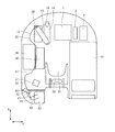
- FIG. 5 is a perspective view showing the arrangement of the exhaust treatment devices 12 and 14 with respect to the counterweight 5.
- FIG. 6 is an exploded perspective view showing the configuration of the counterweight 5 and the rear leg 180.
- FIG. 7 is a partial perspective view showing the configuration of the main part of the counterweight 5.
- FIG. 5 shows the counterweight 5 viewed from the left front.
- FIG. 6 shows the counterweight 5 viewed from the right front.
- FIG. 7 shows a part of the contact portion of the counterweight 5 with the turning frame 31.
- the counterweight 5 is disposed on the turning frame 31 behind the engine 7.
- the counterweight 5 has an inner peripheral surface constituting the rear wall of the engine compartment.
- the inner peripheral surface of the counterweight 5 faces each device mounted on the turning frame 31, such as the engine 7, the fan 8, and the exhaust treatment devices 12 and 14 shown in FIG.
- the inner surface of the counterweight 5 is complicated so that the arrangement of each device adjacent to the counterweight 5 is considered and the volume of the counterweight 5 can be increased as much as possible. An uneven shape is formed.
- a pair of recesses 52 and 53 whose inner peripheral surface is recessed in a groove shape are formed on the inner peripheral surface of the counterweight 5. Between the pair of recesses 52, 53, a protrusion 51 protruding forward with respect to the recesses 52, 53 is formed. The convex portion 51 and the concave portions 52 and 53 extend along the vertical direction.
- the convex portion 51 does not extend to the turning frame 31.
- the convex portion 51 is not in contact with the revolving frame 31, and a space is formed between the lower surface of the convex portion 51 and the upper surface of the revolving frame 31.
- This space is formed as a recess 54 that is recessed with respect to the inner peripheral surface of the counterweight 5.
- the recesses 52 and 53 communicate with the recess 54.
- the concave portions 52 and 53 do not extend to the turning frame 31 like the convex portion 51.
- the range extending along the upper surface of the swivel frame 31 forms the concave portion 54
- the range extending along the convex portion 51 includes the concave portions 52 and 53. Forming.
- the revolving frame 31 is formed with a plurality of (four in the embodiment shown in FIG. 7) through-holes 37.
- the through hole 37 penetrates the turning frame 31 in the thickness direction.
- a part or all of the through hole 37 is formed at a position facing the recess 54 in the revolving frame 31.
- the rear leg portion 180 has a main body portion 180m.
- the main body portion 180m extends in the vertical direction.
- the main body portion 180m functions as a column on which a compressive load is applied in the extending direction.
- the main body portion 180m is formed in a U-shaped cross section.
- the main body 180m has a base 181, a tip 182 and a tip 183 not shown in FIG.
- the base portion 181 and the tip portions 182 and 183 each have a flat plate shape.
- the tip 182 is connected to one of the sides extending in the vertical direction of the base 181, and the tip 183 is connected to the other.
- the extending directions of the base 181 and the tip 182 intersect each other, typically orthogonally.
- the extending directions of the base portion 181 and the tip portion 183 intersect each other, typically orthogonally.
- the tip portion 182 and the tip portion 183 extend in parallel with each other.
- a beam member is connected to the upper end of the main body portion 180m of the rear leg portion 180.
- Support portions 185 are provided at both ends of the beam member.
- the support portion 185 supports the bracket 170 by mounting the bracket 170 thereon.
- a plate-like fixing portion 184 is provided at the lower end of the rear leg portion 180.
- the fixed part 184 is connected to the lower end of the main body part 180m.
- the rear leg 180 is fixed on the turning frame 31, while the counterweight 5 is not mounted on the turning frame 31.
- the relative position is shown.
- the pair of distal end portions 182 and 183 of the main body portion 180m of the rear leg portion 180 is inserted into a pair of groove-shaped concave portions 52 and 53 formed in the counterweight 5, whereby the counterweight 5 and the rear leg portion 180 are inserted. And are arranged in combination.
- the exhaust treatment devices 12 and 14 can be disposed close to the counterweight 5.
- the rear leg portion 180 is not counter. It is not fixed to the weight 5.
- the exhaust treatment devices 12 and 14 supported by the legs including the rear legs 180 with respect to the turning frame 31 and the counterweight 5 are mounted on the turning frame 31 independently of each other.
- FIG. 8 is a perspective view showing the configuration of the fixing portion 184 at the lower end of the rear leg portion 180.
- the main body portion 180m of the rear leg portion 180 has the base portion 181 and the tip portions 182 and 183, and is formed in a U-shaped cross section.
- the fixing portion 184 has a plate shape and is disposed at the lower end of the main body portion 180m.
- a plurality of (four in the embodiment shown in FIG. 8) through-holes are formed in the fixing portion 184.
- the through hole penetrates the fixing portion 184 in the thickness direction.
- a bolt 186 is disposed through the through hole.
- a fixing nut 187 surrounding the through hole is attached to the upper surface of the fixing portion 184, and the bolt 186 is screwed into the fixing nut 187 and attached to the fixing portion 184.
- a bolt 186 is inserted into the through hole 37 (FIG. 7) formed in the swivel frame 31 from the lower surface side of the swivel frame 31, penetrates the through hole formed in the through hole 37 and the fixing portion 184, and reaches the fixing nut 187.
- the fixing portion 184 is fixed to the turning frame 31 by being screwed.
- FIG. 9 is a first sectional view showing the arrangement of the rear legs 180 with respect to the counterweight 5.
- FIG. 9 illustrates a cross section of the rear leg 180 and the counterweight 5 along a plane parallel to the extending direction of the turning frame 31 in a state where the rear leg 180 and the counterweight 5 illustrated in FIG. 5 are combined. ing.
- FIG. 9 shows a cross-sectional view at a position where the convex portion 51 and the concave portions 52 and 53 are formed on the counterweight 5.
- the main body portion 180m of the rear leg portion 180 has a base portion 181 and a pair of tip portions 182 and 183.
- a tip portion 182 is joined to one edge of the plate-like base portion 181, a tip portion 183 is joined to the other edge, and the main body portion 180 m is formed in a U-shaped cross section.
- the U-shaped open side of the main body 180 m faces the counterweight 5.
- the tip portions 182 and 183 are disposed closer to the counterweight 5 than the base portion 181.
- the counterweight 5 is formed with a pair of groove-like recesses 52 and 53.
- One end portion 182 of the rear leg portion 180 is inserted into the one recessed portion 52.
- the other end 183 of the rear leg 180 is inserted into the other recess 53.
- the base 181 is not inserted into the recesses 52 and 53 and is not fitted into the counterweight 5.
- the base 181 is disposed on the front side of the turning frame 31 with respect to the inner peripheral surface of the counterweight 5.
- a convex portion 51 that protrudes from the bottom surface of the concave portions 52 and 53 is formed.
- the convex portion 51 is disposed between a pair of tip portions 182 and 183 of the main body portion 180 m of the rear leg portion 180.
- the convex part 51 is arrange
- the convex portion 51 is surrounded on three sides by the base portion 181 and the tip portions 182 and 183 of the main body portion 180m having a U-shaped cross section.
- the pair of tip portions 182 and 183 are inserted into separate recesses 52 and 53, respectively.
- a convex portion 51 constituting a part of the counterweight 5 is disposed in a region sandwiched between the tip portions 182 and 183.
- the counterweight 5 is not formed with a recess that accommodates both the tip portions 182 and 183, but is separately formed with a recess 52 that accommodates the tip portion 182 and a recess 53 that accommodates the tip portion 183.
- a convex portion 51 is formed between the concave portions 52 and 53 so as to protrude toward the base portion 181 of the rear leg portion 180.
- the counterweight 5 has a convex portion 51, so that its volume is increased.
- FIG. 10 is a second sectional view showing the arrangement of the rear legs 180 with respect to the counterweight 5. Similar to FIG. 9, FIG. 10 shows the rear leg 180 and the counterweight along the plane parallel to the extending direction of the swivel frame 31 in the state where the rear leg 180 and the counterweight 5 shown in FIG. 5 are combined. A cross section of 5 is shown. FIG. 10 shows a cross-sectional view at a position where the recess 54 is formed in the counterweight 5.
- the rear leg 180 has a plate-like fixing part 184 at its lower end.
- the fixing portion 184 is formed with a through hole that penetrates the fixing portion 184 in the thickness direction.
- Bolts 186 are disposed through the turning frame 31 and the fixing portion 184, and the bolts 186 are screwed into the fixing nut 187, whereby the fixing portion 184 is fixed to the turning frame 31.
- the rear leg 180 is fixed to the turning frame 31.
- a recess 54 is formed in the counterweight 5.
- the fixing portion 184 of the rear leg portion 180 is inserted into the recess 54.
- the fixing portion 184 is fixed to the turning frame 31 in a region sandwiched between the pair of tip portions 182 and 183 of the main body portion 180m in plan view. Since the counterweight 5 is formed with the recess 54 into which the fixing portion 184 is inserted, the entire rear leg 180 is combined with the counterweight 5 so that the rear leg 180 is closer to the counterweight 5. It is possible to do.
- FIG. 11 is a cross-sectional view showing a modified example of the arrangement of the rear legs 180 with respect to the counterweight 5.
- FIG. 11 shows a counterweight 5 of a modified example, and shows a cross section of the rear leg 180 and the counterweight 5 at the same vertical position as in FIG.
- the recess 52 into which the tip 182 is inserted similarly to the counterweight 5 shown in FIG. 9, the recess 52 into which the tip 182 is inserted, the recess 53 into which the tip 183 is inserted, and the recesses 52 and 53.
- the convex part 51 between is formed.
- the modified counterweight 5 is further formed with a recess 55 that is recessed with respect to the inner peripheral surface 5 s of the counterweight 5.
- the base 181 of the rear leg 180 is housed inside the recess 55.
- the entire main body 180m of the rear leg 180 is fitted into the counterweight 5 of the modified example.
- the surface of the base 181 and the inner peripheral surface 5s of the counterweight 5 can be arranged on substantially the same plane.
- the hydraulic excavator 1 includes a rear leg 180.
- the rear leg portion 180 constitutes a leg portion that supports the exhaust treatment devices 12 and 14 with respect to the turning frame 31.
- the rear leg portion 180 has a main body portion 180 m formed in a U-shaped cross section, and the U-shaped open side of the main body portion 180 m faces the counterweight 5.
- the counterweight 5 is formed with a pair of groove-like recesses 52 and 53 into which a pair of U-shaped tip portions 182 and 183 of the main body portion 180m are respectively inserted.
- the exhaust treatment devices 12 and 14 can be arranged closer to the counterweight 5. Therefore, the exhaust treatment devices 12 and 14 can be appropriately arranged on the turning frame 31 having a limited area.
- the front end portions 182 and 183 of the rear leg portion 180 are not inserted into the same concave portion, the front end portion 182 is inserted into the groove-shaped concave portion 52, and the front end portion 183 is a groove-shaped concave portion different from the concave portion 52. 53 is inserted.
- a convex portion 51 is formed between the concave portions 52 and 53. Since the convex portion 51 is disposed between the pair of tip portions 182 and 183, the convex portion 51 does not affect the arrangement of the rear leg portion 180 with respect to the counterweight 5.
- the volume of the counterweight 5 can be increased by providing the convex portion 51 that is a part of the counterweight 5 instead of forming a hollow space between the pair of tip portions 182 and 183. Thereby, even if the recessed parts 52 and 53 are formed in the counterweight 5, the weight reduction of the counterweight 5 can be suppressed, and the vehicle body balance of the excavator 1 can be maintained.
- the rear leg 180 has a plate-like fixing portion 184 fixed to the revolving frame 31 at the lower end thereof.
- the counterweight 5 has a recess 54 into which the fixing portion 184 is inserted.
- the recess 54 into which the fixing portion 184 is inserted is formed in the counterweight 5 so that the rear leg 180 In the arrangement in which at least a part is fitted into the counterweight 5, the rear leg 180 can be reliably fixed to the turning frame 31.
- the fixing portion 184 is fixed to the turning frame 31 in a region sandwiched between a pair of U-shaped tip portions 182 and 183 of the main body portion 180m in plan view. In this way, it is not necessary to provide a space for fixing the rear leg portion 180 to the revolving frame 31 outside the U-shape of the main body portion 180m. Therefore, the volume of the concave portion 54 for accommodating the fixing portion 184 can be reduced, and the weight of the counterweight 5 can be more reliably held.
- the excavator 1 is a small rear turning type.
- the area of the turning frame 31 is small, and the counterweight 5 is not heavy enough. Therefore, as described in the present embodiment, the front end portions 182 and 183 of the rear leg portion 180 are inserted into the pair of concave portions 52 and 53 formed in the counterweight 5, and the convex portion 51 is interposed between the concave portions 52 and 53. With the formed configuration, the exhaust treatment devices 12 and 14 can be disposed close to the counterweight 5, and the effect of suppressing the weight reduction of the counterweight 5 can be obtained more remarkably.
- the configuration of the rear leg 180 and the counterweight 5 of the present embodiment may be applied to a leg that supports either the exhaust treatment device 12 or the exhaust treatment device 14 independently.
- the exhaust treatment device supported by the leg frame 31 with respect to the revolving frame 31 may be any exhaust treatment device other than DOC and SCR, or may be an exhaust treatment unit in which a plurality of arbitrary exhaust treatment devices are combined. Good.
Landscapes
- Engineering & Computer Science (AREA)
- General Engineering & Computer Science (AREA)
- Chemical & Material Sciences (AREA)
- Structural Engineering (AREA)
- Civil Engineering (AREA)
- Mining & Mineral Resources (AREA)
- Mechanical Engineering (AREA)
- Combustion & Propulsion (AREA)
- Chemical Kinetics & Catalysis (AREA)
- Toxicology (AREA)
- Health & Medical Sciences (AREA)
- Transportation (AREA)
- Materials Engineering (AREA)
- Component Parts Of Construction Machinery (AREA)
- Jib Cranes (AREA)
Priority Applications (7)
| Application Number | Priority Date | Filing Date | Title |
|---|---|---|---|
| US14/399,318 US9574323B2 (en) | 2014-08-08 | 2014-08-08 | Hydraulic excavator |
| KR1020157017822A KR101676982B1 (ko) | 2014-08-08 | 2014-08-08 | 유압 셔블 |
| PCT/JP2014/071025 WO2015059981A1 (ja) | 2014-08-08 | 2014-08-08 | 油圧ショベル |
| CN201480001059.0A CN104334802B (zh) | 2014-08-08 | 2014-08-08 | 液压挖掘机 |
| JP2014549260A JP5723496B1 (ja) | 2014-08-08 | 2014-08-08 | 油圧ショベル |
| DE112014000107.4T DE112014000107B3 (de) | 2014-08-08 | 2014-08-08 | Hydraulikbagger |
| IN5047DEN2015 IN2015DN05047A (https=) | 2014-08-08 | 2014-08-08 |
Applications Claiming Priority (1)
| Application Number | Priority Date | Filing Date | Title |
|---|---|---|---|
| PCT/JP2014/071025 WO2015059981A1 (ja) | 2014-08-08 | 2014-08-08 | 油圧ショベル |
Publications (1)
| Publication Number | Publication Date |
|---|---|
| WO2015059981A1 true WO2015059981A1 (ja) | 2015-04-30 |
Family
ID=52408636
Family Applications (1)
| Application Number | Title | Priority Date | Filing Date |
|---|---|---|---|
| PCT/JP2014/071025 Ceased WO2015059981A1 (ja) | 2014-08-08 | 2014-08-08 | 油圧ショベル |
Country Status (7)
| Country | Link |
|---|---|
| US (1) | US9574323B2 (https=) |
| JP (1) | JP5723496B1 (https=) |
| KR (1) | KR101676982B1 (https=) |
| CN (1) | CN104334802B (https=) |
| DE (1) | DE112014000107B3 (https=) |
| IN (1) | IN2015DN05047A (https=) |
| WO (1) | WO2015059981A1 (https=) |
Families Citing this family (11)
| Publication number | Priority date | Publication date | Assignee | Title |
|---|---|---|---|---|
| CN107002532B (zh) * | 2014-11-21 | 2019-07-09 | 株式会社Kcm | 产业用车辆 |
| JP6253158B2 (ja) * | 2014-12-15 | 2017-12-27 | キャタピラー エス エー アール エル | 建設機械における還元剤タンクの配設構造 |
| JP6840453B2 (ja) * | 2015-03-20 | 2021-03-10 | 住友建機株式会社 | 小旋回型ショベル |
| WO2015147343A1 (ja) * | 2015-05-21 | 2015-10-01 | 株式会社小松製作所 | 油圧ショベル |
| JP6497737B2 (ja) * | 2015-06-18 | 2019-04-10 | キャタピラー エス エー アール エル | 建設機械におけるカウンタウエイト支持構造 |
| CN105712255B (zh) * | 2016-04-27 | 2018-05-22 | 安徽昌永得机械有限公司 | 一种叉车配重壳体 |
| CN105731310B (zh) * | 2016-04-27 | 2018-05-22 | 安徽昌永得机械有限公司 | 一种叉车配重块 |
| JP1577338S (https=) * | 2016-08-30 | 2017-05-29 | ||
| CN107558526B (zh) * | 2017-10-31 | 2023-08-18 | 三一重机有限公司 | 可调位置钢管管夹支架及液压挖掘机 |
| USD969878S1 (en) | 2019-09-30 | 2022-11-15 | Kubota Corporation | Backhoe loader |
| CN116927276B (zh) * | 2023-07-26 | 2026-04-10 | 上海三一重机股份有限公司 | 回转平台及作业机械 |
Citations (4)
| Publication number | Priority date | Publication date | Assignee | Title |
|---|---|---|---|---|
| WO2008136203A1 (ja) * | 2007-05-01 | 2008-11-13 | Hitachi Construction Machinery Co., Ltd. | 建設機械 |
| WO2011152306A1 (ja) * | 2010-05-31 | 2011-12-08 | 株式会社小松製作所 | 作業車両 |
| JP2012171596A (ja) * | 2011-02-24 | 2012-09-10 | Hitachi Constr Mach Co Ltd | 建設機械 |
| JP2012177233A (ja) * | 2011-02-25 | 2012-09-13 | Hitachi Constr Mach Co Ltd | 建設機械 |
Family Cites Families (15)
| Publication number | Priority date | Publication date | Assignee | Title |
|---|---|---|---|---|
| JP3750849B2 (ja) | 2001-11-16 | 2006-03-01 | 新キャタピラー三菱株式会社 | 建設機械におけるカウンタウエイトの螺子受け体および螺子受け体の芯出し方法 |
| JP4196375B2 (ja) * | 2003-02-04 | 2008-12-17 | 株式会社小松製作所 | カウンタウエイト |
| JP4211919B2 (ja) * | 2003-03-24 | 2009-01-21 | 株式会社小松製作所 | 油圧ショベルのカウンタウエイト |
| JP4123229B2 (ja) * | 2004-12-24 | 2008-07-23 | コベルコ建機株式会社 | 建設機械のカウンタウェイト装置 |
| JP4966100B2 (ja) * | 2007-05-31 | 2012-07-04 | 日立建機株式会社 | 建設機械 |
| JP5160814B2 (ja) * | 2007-05-31 | 2013-03-13 | 日立建機株式会社 | 建設機械 |
| JP4928474B2 (ja) * | 2008-01-08 | 2012-05-09 | 日立建機株式会社 | 建設機械のNOx低減装置の配設構造 |
| JP5101324B2 (ja) * | 2008-02-07 | 2012-12-19 | 日立建機株式会社 | 建設機械のNOx低減装置の配設構造 |
| JP4705130B2 (ja) * | 2008-06-25 | 2011-06-22 | 日立建機株式会社 | 建設機械 |
| JP5654856B2 (ja) * | 2010-11-30 | 2015-01-14 | 株式会社小松製作所 | 油圧ショベル |
| JP5615763B2 (ja) * | 2011-06-14 | 2014-10-29 | 日立建機株式会社 | 建設機械 |
| JP5870779B2 (ja) | 2012-03-13 | 2016-03-01 | コベルコ建機株式会社 | 建設機械のカウンタウェイト装置 |
| JP5442829B1 (ja) | 2012-10-16 | 2014-03-12 | 株式会社小松製作所 | 油圧ショベル |
| JP5949793B2 (ja) * | 2014-01-17 | 2016-07-13 | コベルコ建機株式会社 | 建設機械 |
| JP5949794B2 (ja) * | 2014-01-17 | 2016-07-13 | コベルコ建機株式会社 | 建設機械のツールボックス |
-
2014
- 2014-08-08 IN IN5047DEN2015 patent/IN2015DN05047A/en unknown
- 2014-08-08 DE DE112014000107.4T patent/DE112014000107B3/de active Active
- 2014-08-08 KR KR1020157017822A patent/KR101676982B1/ko not_active Expired - Fee Related
- 2014-08-08 WO PCT/JP2014/071025 patent/WO2015059981A1/ja not_active Ceased
- 2014-08-08 CN CN201480001059.0A patent/CN104334802B/zh active Active
- 2014-08-08 US US14/399,318 patent/US9574323B2/en active Active
- 2014-08-08 JP JP2014549260A patent/JP5723496B1/ja active Active
Patent Citations (4)
| Publication number | Priority date | Publication date | Assignee | Title |
|---|---|---|---|---|
| WO2008136203A1 (ja) * | 2007-05-01 | 2008-11-13 | Hitachi Construction Machinery Co., Ltd. | 建設機械 |
| WO2011152306A1 (ja) * | 2010-05-31 | 2011-12-08 | 株式会社小松製作所 | 作業車両 |
| JP2012171596A (ja) * | 2011-02-24 | 2012-09-10 | Hitachi Constr Mach Co Ltd | 建設機械 |
| JP2012177233A (ja) * | 2011-02-25 | 2012-09-13 | Hitachi Constr Mach Co Ltd | 建設機械 |
Also Published As
| Publication number | Publication date |
|---|---|
| CN104334802A (zh) | 2015-02-04 |
| CN104334802B (zh) | 2016-04-20 |
| JPWO2015059981A1 (ja) | 2017-03-09 |
| JP5723496B1 (ja) | 2015-05-27 |
| KR20160031996A (ko) | 2016-03-23 |
| US9574323B2 (en) | 2017-02-21 |
| IN2015DN05047A (https=) | 2015-07-31 |
| US20160281327A1 (en) | 2016-09-29 |
| DE112014000107B3 (de) | 2015-12-31 |
| KR101676982B1 (ko) | 2016-11-16 |
| DE112014000107T5 (de) | 2016-03-17 |
Similar Documents
| Publication | Publication Date | Title |
|---|---|---|
| JP5723496B1 (ja) | 油圧ショベル | |
| JP5723495B1 (ja) | 油圧ショベル | |
| WO2016002973A1 (ja) | 油圧ショベル | |
| JP5764725B1 (ja) | 油圧ショベル | |
| JP5878675B1 (ja) | 油圧ショベル | |
| JP5723493B1 (ja) | 油圧ショベル | |
| JP5768191B1 (ja) | 油圧ショベル | |
| US9533567B2 (en) | Construction machine | |
| CN107338823B (zh) | 工程机械 | |
| JP5723494B1 (ja) | 油圧ショベル | |
| WO2022049992A1 (ja) | 作業機械 | |
| KR101598770B1 (ko) | 유압 셔블 | |
| KR101578337B1 (ko) | 유압 셔블 | |
| JP2021110121A (ja) | 機体および作業機械 | |
| KR101621674B1 (ko) | 유압 셔블 | |
| JP2016102358A (ja) | 建設機械 |
Legal Events
| Date | Code | Title | Description |
|---|---|---|---|
| WWE | Wipo information: entry into national phase |
Ref document number: 201480001059.0 Country of ref document: CN |
|
| ENP | Entry into the national phase |
Ref document number: 2014549260 Country of ref document: JP Kind code of ref document: A |
|
| WWE | Wipo information: entry into national phase |
Ref document number: 14399318 Country of ref document: US |
|
| WWE | Wipo information: entry into national phase |
Ref document number: 1120140001074 Country of ref document: DE Ref document number: 112014000107 Country of ref document: DE |
|
| ENP | Entry into the national phase |
Ref document number: 20157017822 Country of ref document: KR Kind code of ref document: A |
|
| 121 | Ep: the epo has been informed by wipo that ep was designated in this application |
Ref document number: 14856601 Country of ref document: EP Kind code of ref document: A1 |
|
| 122 | Ep: pct application non-entry in european phase |
Ref document number: 14856601 Country of ref document: EP Kind code of ref document: A1 |