WO2015056526A1 - エンコーダ付組み合わせシールリング及びエンコーダ付転がり軸受ユニット - Google Patents
エンコーダ付組み合わせシールリング及びエンコーダ付転がり軸受ユニット Download PDFInfo
- Publication number
- WO2015056526A1 WO2015056526A1 PCT/JP2014/074930 JP2014074930W WO2015056526A1 WO 2015056526 A1 WO2015056526 A1 WO 2015056526A1 JP 2014074930 W JP2014074930 W JP 2014074930W WO 2015056526 A1 WO2015056526 A1 WO 2015056526A1
- Authority
- WO
- WIPO (PCT)
- Prior art keywords
- encoder
- peripheral surface
- ring
- slinger
- seal ring
- Prior art date
- Legal status (The legal status is an assumption and is not a legal conclusion. Google has not performed a legal analysis and makes no representation as to the accuracy of the status listed.)
- Ceased
Links
Images


Classifications
-
- F—MECHANICAL ENGINEERING; LIGHTING; HEATING; WEAPONS; BLASTING
- F16—ENGINEERING ELEMENTS AND UNITS; GENERAL MEASURES FOR PRODUCING AND MAINTAINING EFFECTIVE FUNCTIONING OF MACHINES OR INSTALLATIONS; THERMAL INSULATION IN GENERAL
- F16J—PISTONS; CYLINDERS; SEALINGS
- F16J15/00—Sealings
- F16J15/16—Sealings between relatively-moving surfaces
- F16J15/34—Sealings between relatively-moving surfaces with slip-ring pressed against a more or less radial face on one member
- F16J15/3492—Sealings between relatively-moving surfaces with slip-ring pressed against a more or less radial face on one member with monitoring or measuring means associated with the seal
-
- F—MECHANICAL ENGINEERING; LIGHTING; HEATING; WEAPONS; BLASTING
- F16—ENGINEERING ELEMENTS AND UNITS; GENERAL MEASURES FOR PRODUCING AND MAINTAINING EFFECTIVE FUNCTIONING OF MACHINES OR INSTALLATIONS; THERMAL INSULATION IN GENERAL
- F16C—SHAFTS; FLEXIBLE SHAFTS; ELEMENTS OR CRANKSHAFT MECHANISMS; ROTARY BODIES OTHER THAN GEARING ELEMENTS; BEARINGS
- F16C33/00—Parts of bearings; Special methods for making bearings or parts thereof
- F16C33/72—Sealings
- F16C33/76—Sealings of ball or roller bearings
- F16C33/78—Sealings of ball or roller bearings with a diaphragm, disc, or ring, with or without resilient members
- F16C33/7816—Details of the sealing or parts thereof, e.g. geometry, material
- F16C33/783—Details of the sealing or parts thereof, e.g. geometry, material of the mounting region
-
- F—MECHANICAL ENGINEERING; LIGHTING; HEATING; WEAPONS; BLASTING
- F16—ENGINEERING ELEMENTS AND UNITS; GENERAL MEASURES FOR PRODUCING AND MAINTAINING EFFECTIVE FUNCTIONING OF MACHINES OR INSTALLATIONS; THERMAL INSULATION IN GENERAL
- F16C—SHAFTS; FLEXIBLE SHAFTS; ELEMENTS OR CRANKSHAFT MECHANISMS; ROTARY BODIES OTHER THAN GEARING ELEMENTS; BEARINGS
- F16C19/00—Bearings with rolling contact, for exclusively rotary movement
- F16C19/02—Bearings with rolling contact, for exclusively rotary movement with bearing balls essentially of the same size in one or more circular rows
- F16C19/04—Bearings with rolling contact, for exclusively rotary movement with bearing balls essentially of the same size in one or more circular rows for radial load mainly
- F16C19/08—Bearings with rolling contact, for exclusively rotary movement with bearing balls essentially of the same size in one or more circular rows for radial load mainly with two or more rows of balls
-
- F—MECHANICAL ENGINEERING; LIGHTING; HEATING; WEAPONS; BLASTING
- F16—ENGINEERING ELEMENTS AND UNITS; GENERAL MEASURES FOR PRODUCING AND MAINTAINING EFFECTIVE FUNCTIONING OF MACHINES OR INSTALLATIONS; THERMAL INSULATION IN GENERAL
- F16C—SHAFTS; FLEXIBLE SHAFTS; ELEMENTS OR CRANKSHAFT MECHANISMS; ROTARY BODIES OTHER THAN GEARING ELEMENTS; BEARINGS
- F16C33/00—Parts of bearings; Special methods for making bearings or parts thereof
- F16C33/72—Sealings
- F16C33/76—Sealings of ball or roller bearings
- F16C33/768—Sealings of ball or roller bearings between relatively stationary parts, i.e. static seals
-
- F—MECHANICAL ENGINEERING; LIGHTING; HEATING; WEAPONS; BLASTING
- F16—ENGINEERING ELEMENTS AND UNITS; GENERAL MEASURES FOR PRODUCING AND MAINTAINING EFFECTIVE FUNCTIONING OF MACHINES OR INSTALLATIONS; THERMAL INSULATION IN GENERAL
- F16C—SHAFTS; FLEXIBLE SHAFTS; ELEMENTS OR CRANKSHAFT MECHANISMS; ROTARY BODIES OTHER THAN GEARING ELEMENTS; BEARINGS
- F16C33/00—Parts of bearings; Special methods for making bearings or parts thereof
- F16C33/72—Sealings
- F16C33/76—Sealings of ball or roller bearings
- F16C33/78—Sealings of ball or roller bearings with a diaphragm, disc, or ring, with or without resilient members
- F16C33/7816—Details of the sealing or parts thereof, e.g. geometry, material
- F16C33/782—Details of the sealing or parts thereof, e.g. geometry, material of the sealing region
- F16C33/7823—Details of the sealing or parts thereof, e.g. geometry, material of the sealing region of sealing lips
-
- F—MECHANICAL ENGINEERING; LIGHTING; HEATING; WEAPONS; BLASTING
- F16—ENGINEERING ELEMENTS AND UNITS; GENERAL MEASURES FOR PRODUCING AND MAINTAINING EFFECTIVE FUNCTIONING OF MACHINES OR INSTALLATIONS; THERMAL INSULATION IN GENERAL
- F16C—SHAFTS; FLEXIBLE SHAFTS; ELEMENTS OR CRANKSHAFT MECHANISMS; ROTARY BODIES OTHER THAN GEARING ELEMENTS; BEARINGS
- F16C33/00—Parts of bearings; Special methods for making bearings or parts thereof
- F16C33/72—Sealings
- F16C33/76—Sealings of ball or roller bearings
- F16C33/78—Sealings of ball or roller bearings with a diaphragm, disc, or ring, with or without resilient members
- F16C33/7869—Sealings of ball or roller bearings with a diaphragm, disc, or ring, with or without resilient members mounted with a cylindrical portion to the inner surface of the outer race and having a radial portion extending inward
- F16C33/7879—Sealings of ball or roller bearings with a diaphragm, disc, or ring, with or without resilient members mounted with a cylindrical portion to the inner surface of the outer race and having a radial portion extending inward with a further sealing ring
- F16C33/7883—Sealings of ball or roller bearings with a diaphragm, disc, or ring, with or without resilient members mounted with a cylindrical portion to the inner surface of the outer race and having a radial portion extending inward with a further sealing ring mounted to the inner race and of generally L-shape, the two sealing rings defining a sealing with box-shaped cross-section
-
- F—MECHANICAL ENGINEERING; LIGHTING; HEATING; WEAPONS; BLASTING
- F16—ENGINEERING ELEMENTS AND UNITS; GENERAL MEASURES FOR PRODUCING AND MAINTAINING EFFECTIVE FUNCTIONING OF MACHINES OR INSTALLATIONS; THERMAL INSULATION IN GENERAL
- F16C—SHAFTS; FLEXIBLE SHAFTS; ELEMENTS OR CRANKSHAFT MECHANISMS; ROTARY BODIES OTHER THAN GEARING ELEMENTS; BEARINGS
- F16C41/00—Other accessories, e.g. devices integrated in the bearing not relating to the bearing function as such
- F16C41/007—Encoders, e.g. parts with a plurality of alternating magnetic poles
-
- F—MECHANICAL ENGINEERING; LIGHTING; HEATING; WEAPONS; BLASTING
- F16—ENGINEERING ELEMENTS AND UNITS; GENERAL MEASURES FOR PRODUCING AND MAINTAINING EFFECTIVE FUNCTIONING OF MACHINES OR INSTALLATIONS; THERMAL INSULATION IN GENERAL
- F16J—PISTONS; CYLINDERS; SEALINGS
- F16J15/00—Sealings
- F16J15/16—Sealings between relatively-moving surfaces
- F16J15/34—Sealings between relatively-moving surfaces with slip-ring pressed against a more or less radial face on one member
- F16J15/3436—Pressing means
- F16J15/3456—Pressing means without external means for pressing the ring against the face, e.g. slip-ring with a resilient lip
-
- F—MECHANICAL ENGINEERING; LIGHTING; HEATING; WEAPONS; BLASTING
- F16—ENGINEERING ELEMENTS AND UNITS; GENERAL MEASURES FOR PRODUCING AND MAINTAINING EFFECTIVE FUNCTIONING OF MACHINES OR INSTALLATIONS; THERMAL INSULATION IN GENERAL
- F16C—SHAFTS; FLEXIBLE SHAFTS; ELEMENTS OR CRANKSHAFT MECHANISMS; ROTARY BODIES OTHER THAN GEARING ELEMENTS; BEARINGS
- F16C19/00—Bearings with rolling contact, for exclusively rotary movement
- F16C19/02—Bearings with rolling contact, for exclusively rotary movement with bearing balls essentially of the same size in one or more circular rows
- F16C19/14—Bearings with rolling contact, for exclusively rotary movement with bearing balls essentially of the same size in one or more circular rows for both radial and axial load
- F16C19/18—Bearings with rolling contact, for exclusively rotary movement with bearing balls essentially of the same size in one or more circular rows for both radial and axial load with two or more rows of balls
- F16C19/181—Bearings with rolling contact, for exclusively rotary movement with bearing balls essentially of the same size in one or more circular rows for both radial and axial load with two or more rows of balls with angular contact
- F16C19/183—Bearings with rolling contact, for exclusively rotary movement with bearing balls essentially of the same size in one or more circular rows for both radial and axial load with two or more rows of balls with angular contact with two rows at opposite angles
- F16C19/184—Bearings with rolling contact, for exclusively rotary movement with bearing balls essentially of the same size in one or more circular rows for both radial and axial load with two or more rows of balls with angular contact with two rows at opposite angles in O-arrangement
- F16C19/186—Bearings with rolling contact, for exclusively rotary movement with bearing balls essentially of the same size in one or more circular rows for both radial and axial load with two or more rows of balls with angular contact with two rows at opposite angles in O-arrangement with three raceways provided integrally on parts other than race rings, e.g. third generation hubs
-
- F—MECHANICAL ENGINEERING; LIGHTING; HEATING; WEAPONS; BLASTING
- F16—ENGINEERING ELEMENTS AND UNITS; GENERAL MEASURES FOR PRODUCING AND MAINTAINING EFFECTIVE FUNCTIONING OF MACHINES OR INSTALLATIONS; THERMAL INSULATION IN GENERAL
- F16C—SHAFTS; FLEXIBLE SHAFTS; ELEMENTS OR CRANKSHAFT MECHANISMS; ROTARY BODIES OTHER THAN GEARING ELEMENTS; BEARINGS
- F16C2326/00—Articles relating to transporting
- F16C2326/01—Parts of vehicles in general
- F16C2326/02—Wheel hubs or castors
Definitions
- the present invention relates to a combined seal ring with an encoder for closing an opening end portion of a rolling bearing incorporated in a rotation support portion of various mechanical devices, and detecting a rotation speed of a rotating member supported by the rolling bearing, and the encoder
- the present invention relates to an improvement of a rolling bearing unit with an encoder provided with a combined seal ring. Specifically, a structure capable of ensuring the sealing performance of the fitting portion between the rotating cylindrical portion constituting the slinger and the outer peripheral surface of the inner diameter side race ring member is realized.
- a rotation support part of various machine devices for example, a wheel support rolling bearing unit for supporting a wheel of a vehicle (automobile) on a suspension device can be cited.
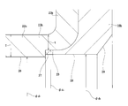
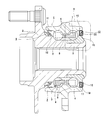
- a rolling bearing unit 1 with an encoder as shown in FIGS. 9 to 10 has been widely known (see, for example, Patent Documents 1 and 2).
- an outer ring 2 that is an outer diameter side race ring member and a hub 3 that is an inner diameter side race ring member are arranged concentrically with each other.
- each ball 6 is a rolling element.
- 6 are arranged in plural for both rows. The balls 6 and 6 are held by the cages 7 and 7 so as to freely roll.
- the hub 3 is rotatably supported on the inner diameter side of the outer ring 2 supported and fixed to the suspension device.
- both ends in the axial direction of the annular space 8 in which the balls 6 and 6 are installed are respectively formed by a seal ring 9 and a combined seal ring 10 with an encoder. It is clogged up around the perimeter.
- the seal ring 9 includes a metal core 11 made of a metal plate and a plurality of seal lips 12 made of an elastic material. And the metal core 11 is the outer end in the axial direction of the outer ring 2 (outside with respect to the axial direction means the left side of each figure on the outer side in the width direction of the vehicle body when assembled to the automobile.
- the center side in the width direction on the right side is referred to as the inside in the axial direction (the same applies throughout the present specification), and the end edge of each seal lip 12 is connected to the intermediate portion in the axial direction of the hub 3 with an interference fit.
- the outer peripheral surface is in sliding contact with the entire periphery.
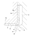
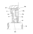
- the combined seal ring 10 with an encoder includes a seal ring 14 and a slinger 15 that constitute the combined seal ring 13, and an encoder 16.
- the seal ring 14 includes a cored bar 17 having an L-shaped cross section and an annular shape as a whole, and an elastic material 18.
- the cored bar 17 is formed of a metal plate such as a mild steel plate and is formed in an annular shape as a whole with an L-shaped cross section.
- the metal core 17 is fixed to the inner peripheral surface of the inner end portion in the axial direction of the outer ring 2 by an interference fit, and from the outer end edge in the axial direction of the fixed cylindrical portion 19 toward the outer peripheral surface of the hub 3.
- a fixed annular portion 20 that is bent inward in the radial direction.
- the elastic member 18 is attached over the entire circumference of the core metal 17 and has one to a plurality of (three in the illustrated example) seal lips 21a to 21c.
- the elastic material 18 is made of rubber and is bonded to the core
- the slinger 15 includes a rotating cylindrical portion 22 that is fitted and fixed to the outer peripheral surface of the inner end portion in the axial direction of the hub 3 (the inner ring that constitutes the hub 3 together with the hub body), and the axial direction of the rotating cylindrical portion 22.
- a rotating ring portion 23 that is bent radially outward from the inner end edge toward the inner peripheral surface of the outer ring 2 is provided.
- the slinger 15 has smooth surfaces at the outer peripheral surface of the rotating cylindrical portion 22 and the axially outer surface of the rotating annular portion 23 where the tip edges of the seal lips 21a to 21c are slidably contacted.
- the encoder 16 is made of a permanent magnet such as a rubber magnet or a plastic magnet, and is magnetized in the axial direction.
- the magnetization direction is changed alternately and at equal intervals in the circumferential direction. Therefore, the south pole and the north pole are alternately arranged at equal intervals in the circumferential direction on the inner side surface in the axial direction of the encoder 16 that is the detection surface.
- the detection surface of the sensor is opposed to the detection surface of such an encoder 16 so that the rotational speed of the wheel rotating together with the hub 3 can be measured.
- the signal showing the measured rotational speed of a wheel is utilized for control of the travel stabilization apparatus of vehicles, such as an anti-lock brake system (ABS) and a traction control system (TCS).
- ABS anti-lock brake system
- TCS traction control system
- the combined seal ring 10 with the encoder can effectively prevent the entry of relatively large foreign matters such as dust, but sufficiently prevents the entry of rainwater, muddy water, and the like. Things are difficult.
- the combined seal ring 10 with an encoder is merely configured to externally fix the rotating cylindrical portion 22 of the slinger 15 to the outer peripheral surface of the inner end portion in the axial direction of the hub 3 and provide a structure for sealing the fitting portion. Not. Even when the rotating cylindrical portion 22 of the slinger 15 is externally fitted to the outer peripheral surface of the inner end portion in the axial direction of the hub 3, it is inevitable that a minute gap is generated in the fitting portion.
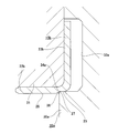
- Patent Document 3 proposes to use a combined seal ring 10a with an encoder as shown in FIG. 11 for the purpose of preventing rain water and the like from entering the annular space as described above.
- a lip portion 24 having an inner diameter smaller than the inner diameter of the rotating cylindrical portion 22a of the slinger 15a is provided on the inner peripheral edge of the encoder 16a. The lip portion 24 is elastically brought into contact with the outer peripheral surface of the hub 3a in a state where the rotating cylindrical portion 22a of the slinger 15a is fitted and fixed to the hub 3a.
- the sealing performance of the fitting portion between the rotating cylindrical portion 22a of the slinger 15a and the outer peripheral surface of the hub 3a is sufficiently ensured for the following reason. Things are difficult. That is, the material constituting the lip portion 24 is the same as that of the encoder 16a, and contains a large amount (for example, 80 to 90% by weight) of a ferromagnetic material such as ferrite in order to ensure sufficient magnetism. Compared to general sealing materials, it is difficult to elastically deform and is brittle.
- the encoder 16a arranges the slinger 15a in a molding die (mold), and fixes a permanent magnet material (high molecular material such as rubber or synthetic resin containing a ferromagnetic material) to the slinger 15a. (Fixed by vulcanization or injection molding).
- a permanent magnet material high molecular material such as rubber or synthetic resin containing a ferromagnetic material
- the encoder 16a is manufactured in this way, when the slinger 15a and the solidified permanent magnet material (unmagnetized encoder) are extracted from the mold, the portion to be the lip portion 24 has a large fastening margin. It must be greatly deformed accordingly (must be forcibly removed). Since it is difficult to greatly deform the portion to be the lip portion 24 in this way, it is difficult to ensure a large allowance for the lip portion 24.
- the rotating cylindrical portion 22a of the slinger 15a is fitted and fixed to the hub 3a by an interference fit, the rotating cylindrical portion 22a is elastically expanded in diameter, but the rotating cylindrical portion 22a and the rotating annular portion 23a are continuous. Therefore, the influence of the diameter expansion of the rotating cylindrical portion 22a is easily transmitted to the rotating annular portion 23a. For this reason, the diameter of the encoder 16a supported and fixed to the rotating ring portion 23a is also easily increased, and the amount of reduction in the tightening allowance of the lip portion 24 is increased.
- Japanese Unexamined Patent Publication No. 2008-233110 Japanese Unexamined Patent Publication No. 2009-185965 Japanese Unexamined Patent Publication No. 2007-52036
- the present invention provides a seal ring with an encoder and a rolling with an encoder that can improve the sealing performance of a fitting portion between a rotating cylindrical portion constituting a slinger and an outer peripheral surface of an inner diameter side race ring member. Invented to realize the structure of the bearing unit.
- the combined seal ring with an encoder of the present invention is an annular space that exists between the outer peripheral surface of the inner diameter side race ring member that rotates during use and the inner peripheral surface of the outer diameter side race ring member that does not rotate during use.
- a slinger externally fitted to the slinger, and an encoder supported and fixed to the slinger.
- the seal ring includes a cored bar and an elastic material having at least one seal lip attached to the entire circumference of the cored bar.
- the slinger is formed by bending a metal plate so as to have a substantially L-shaped cross section and is formed into an annular shape as a whole. And a rotating ring part that is bent radially outward from one axial end edge of the rotating cylindrical part.
- the encoder is made of a permanent magnet in which S poles and N poles are alternately arranged in the circumferential direction, and the whole is configured in a ring shape. Is supported and fixed to the side surface opposite to the side surface facing the.
- the inner peripheral surface of the rotating cylindrical portion includes a large diameter portion provided on one axial end side of the rotating cylindrical portion, and a small diameter portion provided on the remaining portion. Is a stepped cylindrical surface made continuous by a stepped portion.
- the encoder has no lip on its inner peripheral surface, and the molten permanent magnet is disposed in a state in which the slinger is disposed in the mold and a part of the mold is abutted against the stepped portion. It is assumed that the raw material ⁇ rubber mixed with a ferromagnetic material such as ferrite or a polymer material such as synthetic resin (for example, plastic) ⁇ is solidified and fixed to the slinger.
- the outer diameter of the outer peripheral surface of the inner diameter side race ring member for fitting and fixing the slinger is ⁇ D
- the inner diameter in the free state of the small diameter portion is ⁇ d1
- the encoder in the free state When the inner diameter is ⁇ d2, the relationship ⁇ d1 ⁇ ⁇ d2 ⁇ D is satisfied.
- the radial thickness (wall thickness) of the rotating cylindrical portion is set to the small diameter with respect to the axial direction. It is made smaller at the portion that matches the large diameter portion than the portion that matches the portion. Further, for example, as in the third aspect of the invention, at least a part of the inner circumferential surface of the encoder having the smallest inner diameter dimension is supported in the axial direction, and the encoder is supported in the rotating ring portion. It is located on the side farther from the fixed cylindrical part in the axial direction than the fixed side surface.
- the portion of the inner peripheral surface of the encoder having the smallest inner diameter dimension is a single cylindrical surface shape in which the inner diameter dimension ( ⁇ d2) does not change in the axial direction.
- the cylindrical surface portion is used.
- a rolling bearing unit with an encoder includes an inner diameter side bearing ring member (for example, a hub) having an inner ring raceway on an outer peripheral surface, an outer diameter side bearing ring member (for example, an outer ring) having an outer ring raceway on an inner peripheral surface, and the inner ring A plurality of rolling elements (eg, balls, cylindrical rollers, tapered rollers) provided between a raceway and the outer ring raceway, a peripheral surface of the inner diameter side raceway member, and the outer diameter side raceway ring member And a combination seal ring that closes the end opening of the annular space existing between the inner peripheral surface and the inner peripheral surface.
- the combined seal ring is the combined seal ring with an encoder according to any one of claims 1 to 4.
- the sealing performance of the fitting portion between the rotating cylindrical portion constituting the slinger and the outer peripheral surface of the inner diameter side race ring member is good.
- the inner peripheral surface of the rotating cylindrical portion constituting the slinger is a stepped portion between a large diameter portion provided at one axial end of the rotating cylindrical portion and a small diameter portion provided at the remaining portion.
- the stepped cylindrical surface is made continuous.
- this small diameter portion By elastically deforming the portion that matches the large diameter portion provided between the rotating ring portion and the rotating ring portion, it is possible to effectively prevent the influence of the expansion of the small diameter portion from being transmitted to the rotating ring portion.
- the rotating ring portion has a high rigidity in the radial direction because of its shape. Accordingly, since the encoder can be effectively prevented from expanding in diameter, the inner diameter dimension of the encoder can be maintained smaller than the outer diameter dimension of the outer peripheral surface of the inner diameter side race ring member to which the slinger is fitted and fixed. .
- the inner peripheral surface of the encoder can be brought into contact with the outer peripheral surface of the inner diameter side race ring member in a state where the entire periphery has a tightening allowance. Further, since an encoder made by solidifying a permanent magnet material is used, it is advantageous in increasing the tightening allowance. That is, the inner diameter dimension of the non-magnetized encoder after being taken out from the mold becomes smaller than the outer diameter dimension of the portion that forms the inner peripheral surface of the encoder in the inner surface of the mold as it solidifies.
- the margin can be increased even if the inner peripheral edge of the unmagnetized encoder is not deformed or the amount of deformation is kept small.
- the lip is not provided on the inner peripheral surface of the encoder, when the slinger is fitted and fixed to the inner ring-side raceway member, the inner diameter dimension is the smallest among the inner peripheral surfaces of the encoder. The adjacent portion including the formed portion is compressed in the radial direction by contact with the outer peripheral surface of the inner diameter side race ring member.
- the compressive force generated at the inner peripheral edge of the encoder in this way generates a greater compressive force than the compressive force generated based on the bending deformation of the lip. For this reason, even if the tightening allowance is small as compared with the case where the lip is provided, a sufficiently large tightening force can be generated by the inner peripheral surface of the encoder. As a result, according to the present invention, the sealing performance of the fitting portion between the rotating cylindrical portion constituting the slinger and the outer peripheral surface of the inner diameter side race ring member can be improved.
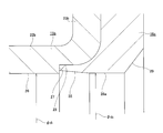
- the fragmentary sectional view which takes out and shows the combination seal ring with an encoder which shows the 1st example of embodiment of this invention.
- the enlarged view of the part corresponded to the A section of FIG.
- the fragmentary sectional view which shows the state which set the slinger to the shaping
- the fragmentary sectional view which shows another example similarly.
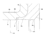
- the figure similar to FIG. 1 which shows the 2nd example of embodiment of this invention.
- the same figure as FIG. The figure similar to FIG. 1 which shows the 3rd example of embodiment of this invention.
- FIG. Sectional drawing which shows an example of the rolling bearing unit with an encoder known conventionally.
- the B section enlarged view of FIG. The fragmentary sectional view equivalent to FIG. 10 which shows the 2nd example of a conventional structure.
- FIGS. 1-10 A first example of the embodiment of the present invention will be described with reference to FIGS.
- the feature of this example is the structure of the portion that improves the sealing performance of the fitting portion between the rotating cylindrical portion 22b of the slinger 15b and the outer peripheral surface of the hub 3 by using the inner peripheral edge portion of the encoder 16b. Since the configuration and operational effects of other parts, including the entire structure of the rolling bearing unit with encoder, are basically the same as those in the first example of the conventional structure described above, the same reference numerals are used for the equivalent parts. The overlapping illustrations and explanations will be omitted or simplified, and the following description will focus on the features of this example.
- the combined seal ring with an encoder 10b of this example is composed of a seal ring 14 and a slinger 15b that constitute the combined seal ring 13a, and an encoder 16b.
- the seal ring 14 includes a cored bar 17 and an elastic material 18.
- the metal core 17 is formed by bending a metal plate such as a mild steel plate by press working to form an annular shape with an L-shaped cross section.
- the cored bar 17 has a fixed cylindrical portion 19 that is fitted and fixed to the inner peripheral surface of the outer ring 2 that is the outer diameter side race ring member by an interference fit on the inner peripheral surface of the outer ring 2, and a diameter from the outer edge in the axial direction of the fixed cylindrical portion 19.
- a fixed ring portion 20 that is bent inward in the direction.
- the elastic member 18 is made of an elastomer such as rubber, and is attached over the entire circumference of the cored bar 17 and has three seal lips 21a to 21c.
- the slinger 15b is formed by bending a metal plate such as a ferritic stainless steel plate such as SUS430 by press working to form an annular shape with an L-shaped cross section.
- the slinger 15b includes a rotating cylindrical portion 22b that is fitted and fixed to the outer peripheral surface of the inner end portion in the axial direction of the hub 3 (the inner ring that constitutes the hub 3 together with the hub main body) that is an inner raceway member, and a rotating cylinder. And a rotating annular ring portion 23b that is bent radially outward from an axially inner end edge (corresponding to one axial end edge recited in the claims) of the portion 22b.
- the portions of the outer peripheral surface of the rotating cylindrical portion 22b and the outer surface in the axial direction of the rotating annular portion 23b that are in sliding contact with the tip edges of the seal lips 21a to 21c are smooth surfaces.
- the distal end edge of the outer seal lip 21a which is called the side lip, is arranged on the outermost radial direction and protrudes inward in the axial direction.
- 23b is slidably brought into contact with the outer circumferential surface of 23b.
- the leading edges of the remaining two intermediate and inner seal lips 21b and 21c are slidably contacted with the outer peripheral surface of the rotating cylindrical portion 22b over the entire circumference.
- the inner peripheral surface of the rotating cylindrical portion 22b is a stepped cylindrical surface.
- a large-diameter portion 25 is formed on the inner peripheral surface of the rotating cylindrical portion 22b on the inner end side in the axial direction of the rotating cylindrical portion 22b, and a smaller diameter is formed on the remaining portion (the axially outer end portion to the inner end portion).
- a portion 26 is formed.
- the large-diameter portion 25 and the small-diameter portion 26 are continued by an annular step portion 27.
- the radial thickness (wall thickness) of the rotating cylindrical portion 22b is made smaller at the portion (t) aligned with the large diameter portion 25 than at the portion (T) aligned with the small diameter portion 26 in the axial direction.
- a value 1 ⁇ 2 of the difference between the inner diameter dimension ( ⁇ d3) of the large diameter portion 25 and the inner diameter dimension ( ⁇ d1) of the small diameter portion 26 ⁇ ( ⁇ d3 ⁇ d1) / 2 ⁇ is set to about 1/10 to 1/4 of the wall thickness (T) of the metal plate (portion other than the large diameter portion 25) constituting the slinger 15b.
- the inner diameter dimension ( ⁇ d1) of the small diameter portion 26 of the rotating cylindrical portion 22b is set in the axial direction of the hub 3.
- the step portion 27 (and the large diameter portion 25) can be formed in advance when the slinger 15b is manufactured by press working, or when the encoder 16b is manufactured by using a molding die (32a) described later. Can also be processed.
- the encoder 16b is supported and fixed concentrically with the slinger 15b on the inner side surface in the axial direction of the rotating ring portion 23b of the slinger 15b (the side surface opposite to the side surface facing the seal lips 21a to 21c).
- the encoder 16b is made of a permanent magnet such as a rubber magnet or a plastic magnet.
- the encoder 16b has a ring shape as a whole, and is magnetized in the axial direction. The magnetization direction is changed alternately and at equal intervals in the circumferential direction. Therefore, the south pole and the north pole are alternately arranged at equal intervals in the circumferential direction on the inner side surface in the axial direction of the encoder 16b, which is the detected surface.
- the inner peripheral surface of the encoder 16b is formed in a single cylindrical surface cylindrical surface portion 28 formed in a range extending from the axial outer end portion to the inner end portion, and the axial inner end portion.
- the lip portion 24 (see FIG. 11) as in the case of the second example of the conventional structure described above is not provided.
- the axially inner half portion of the cylindrical surface portion 28 having the smallest inner diameter dimension is positioned axially inward from the axial inner surface of the rotating ring portion 23b. Yes.
- the inner diameter dimension ( ⁇ d2) of the cylindrical surface portion 28 in a free state before the slinger 15b is fitted and fixed to the hub 3 is smaller than the outer diameter dimension ( ⁇ D) of the inner end portion in the axial direction of the hub 3, and
- the inner diameter dimension ( ⁇ d1) of the small-diameter portion 26 is larger ( ⁇ d1 ⁇ d2 ⁇ D).
- the size of the interference when the slinger 15b is externally fixed to the hub 3 by interference fitting is about 0.15 to 0.3% of the outer diameter ( ⁇ D) of the hub 3 (0.997 ⁇ In many cases, ⁇ D ⁇ d1 ⁇ 0.9985 ⁇ ⁇ D) is set.
- the extent to which the inner diameter dimension ( ⁇ d2) of the encoder 16b is larger than the inner diameter dimension ( ⁇ d1) of the small diameter portion 26 (diameter difference ⁇ d2 ⁇ d1) is 0.05 to 0. 0 of the inner diameter dimension ( ⁇ d2) of the encoder 16b. It can be about 25% (0.995 ⁇ ⁇ d2 ⁇ d1 ⁇ 0.9975 ⁇ ⁇ d2).
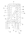
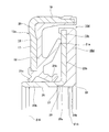
- the encoder 16b having the above-described configuration is manufactured by using a molding die (die) 32 (32a) made of a metal and made up of a pair of upper die 30 (30a) and lower die 31.
- a molding die (die) 32 (32a) made of a metal and made up of a pair of upper die 30 (30a) and lower die 31.
- the slinger 15b is replaced with the annular cavity of the mold 32 as shown in FIG.
- the stepped portion 27 is disposed in a state where the corner portion 34 provided on the outer peripheral edge of the central portion of the upper mold 30 is abutted.
- the slinger 15b is replaced with the cavity 33a of the mold 32a as shown in FIG.
- the corner portion 34a provided at the outer peripheral edge of the central portion of the cemented carbide upper mold 30a is driven into the inner peripheral surface of the rotating cylindrical portion 22b, and the rotating cylindrical portion is plastically deformed.
- the step portion 27 and the large diameter portion 25 are formed on the inner peripheral surface of 22b (the remaining portion is the small diameter portion 26), and the corner portion 34a is abutted against the step portion 27.
- the reason why the corner portion 34 (34a) of the upper mold 30 (30a) abuts on the step portion 27 is to press the molten permanent magnet material into the cavity 33 (33a) as described below. This is to prevent the occurrence of flushing such that the permanent magnet material leaks to the portion of the inner peripheral surface of the rotating cylindrical portion 22b that does not need to be covered by the encoder 16b when it is fed in a state. As shown in FIG. 4, when the inner peripheral surface of the rotating cylindrical portion 22b of the slinger 15b is plastically deformed by the corner portion 34a of the upper mold 30a, the step portion of the inner peripheral surface of the rotating cylindrical portion 22b.
- a surplus part (burr) 36 protruding inward in the radial direction is formed in front of the portion 27 (axially outward). For this reason, in the case of this example, the plastic deformation amount (the radial dimension and the axial length of the part to be plastically deformed) so that the inner diameter dimension of the surplus portion 36 does not become smaller than the inner diameter dimension of the small diameter portion 26. Is regulated.
- a molten permanent magnet material ⁇ rubber or synthetic resin (plastic) or the like is placed in the cavity 33 (33a).
- a high-molecular material mixed with, for example, 80 to 90% by weight of a ferromagnetic material such as ferrite ⁇ is fed in a pressurized state.
- the magnetic strength after magnetization can be increased.
- the permanent magnet material is fixed to the inner side surface in the axial direction of the rotating ring portion 23b of the slinger 15b (adhered by vulcanization adhesion or injection molding).
- the slinger 15b and the non-magnetized encoder (solidified permanent magnet material) are extracted from the mold 32 (32a), and the non-magnetized encoder is subjected to an annealing process in which secondary heating is performed using a furnace such as an oven.
- a furnace such as an oven.
- the temperature is raised from room temperature to 150 to 200 ° C. over 3 to 4 hours, held at the increased temperature for 2 to 4 hours, and then cooled to room temperature over 3 to 5 hours).
- a synthetic resin when used as a permanent magnet material, crystallization is advanced to reduce residual stress, thereby obtaining dimensional stability and improving strength.
- the permanent magnet material is nitrile rubber
- the annealing process is less necessary than other types of rubber because most of the crosslinking is completed during vulcanization molding. Doing so increases cross-linking and improves strength. In the case of acrylic rubber or fluoro rubber, be sure to do it.
- the unmagnetized encoder is magnetized in the axial direction with the unmagnetized encoder facing a magnetized yoke (not shown).
- This kind of magnetizing work involves rotating the non-magnetized encoder as a magnetized yoke in addition to a circular magnet that simultaneously magnetizes (performs one-shot magnetization) the entire surface to be detected of the non-magnetized encoder.
- a rotary magnetizing type that sequentially magnetizes can also be used.
- an annular permanent magnet in which S poles and N poles are alternately arranged at equal intervals over the circumferential direction on the inner side surface in the axial direction, which is the detected surface.
- a manufactured encoder 16b is obtained.
- the encoder combined seal ring 10a of the present example having the above-described configuration is configured such that the fixed cylindrical portion 19 of the core metal 17 is fitted and fixed to the outer ring 2 that does not rotate even during use, and the rotary cylindrical portion 22b of the slinger 15b
- the small-diameter portion 26 is externally fixed to the hub 3 that rotates during use. In this state, the tip edges of the seal lips 21a to 21c are brought into sliding contact with the entire surface of the slinger 15b so as to close the axial inner end opening of the annular space 8 (see FIG. 9).
- the sealing performance of the fitting portion between the rotating cylindrical portion 22b of the slinger 15b and the outer peripheral surface of the hub 3 can be improved in a state where the combined seal ring with encoder 10a is assembled as described above. That is, in the case of this example, the inner peripheral surface of the rotating cylindrical portion 22b of the slinger 15b is a stepped cylindrical surface in which the large diameter portion 25 and the small diameter portion 26 are continuous by the step portion 27. For this reason, when the small diameter portion 26 is externally fixed to the outer peripheral surface of the hub 3 by an interference fit, even when the portion aligned with the small diameter portion 26 in the axial direction is elastically expanded, the small diameter portion 26 rotates.
- a portion having a smaller radial diameter than a portion matching the small-diameter portion 26 provided between the annular portion 23b and a portion matching the large-diameter portion 25 is elastically deformed, thereby reducing the small-diameter portion. It is possible to effectively prevent the influence of the 26 diameter expansion from being transmitted to the rotating ring portion 23b. Further, the rotating ring portion 23b has high radial rigidity due to its shape. Accordingly, since the encoder 16b can be effectively prevented from expanding in diameter, the inner diameter dimension of the encoder 16b can be kept smaller than the outer diameter dimension of the outer peripheral surface of the hub 3 where the slinger 15b is fitted and fixed.
- the axially inner half portion of the cylindrical surface portion 28 is positioned axially inward from the axially inner side surface of the rotating ring portion 23b. Since the axial distance to the inner half of the axial direction 28 is increased, the influence of the diameter expansion of the small diameter portion 26 can hardly be transmitted to the inner half of the cylindrical surface portion 28. For this reason, according to the structure of this example, the cylindrical surface portion 28 of the inner peripheral surface of the encoder 16b can be brought into contact with the outer peripheral surface of the hub 3 in a state of having a tightening margin on the entire periphery (particularly, In the case of this example, the tightening allowance of the inner half of the cylindrical surface portion 28 is larger than the allowance of the outer half of the axial direction).
- the encoder 16b is made by solidifying a permanent magnet material, it is advantageous in increasing the tightening allowance. That is, the inner diameter of the unmagnetized encoder after being taken out from the mold 32 (32a) is outside the portion of the inner surface of the mold 32 (32a) that forms the inner peripheral surface of the encoder 16b as the solidification occurs. It becomes smaller than the diameter dimension. Therefore, when the slinger 15b and the non-magnetized encoder are extracted from the mold 32 (32a), the inner margin of the non-magnetized encoder is not deformed or even if the deformation amount is kept small. Can be increased.
- rubber or synthetic resin which is a permanent magnet material
- rubber or synthetic resin which is a permanent magnet material
- the inner diameter is Although it is reduced by about 0.5 to 1%, the reduction ratio of the inner diameter is small in the case of containing about 80 to 90% by weight of a magnetic material and fixed to the slinger 15b. For this reason, the inner diameter dimension of the encoder 16b does not become smaller than the inner diameter dimension of the small diameter portion 26 (the relationship of ⁇ d1 ⁇ d2 is maintained).
- the tightening allowance can be further increased.
- the sealing performance of the fitting portion between the rotating cylindrical portion 22b of the slinger 15b and the outer peripheral surface of the hub 3 can be improved.
- Other configurations and operational effects are the same as those of the first example of the conventional structure described above.
- FIGS. 1-10 A second example of the embodiment of the present invention will be described with reference to FIGS.
- This example is suitable for the case where the content of the magnetic material is small (for example, 50 to 70% by weight) as compared with the case of the first example of the above-described embodiment as a permanent magnet material for manufacturing the encoder 16c.
- the inner peripheral surface of the encoder 16c is inclined in a direction in which the inner diameter dimension becomes smaller toward the inner side in the axial direction, and a partially conical cylindrical surface portion 35 provided at the outer end portion in the axial direction, and an intermediate portion in the axial direction. It is composed of a cylindrical surface portion 28a provided and a chamfered portion 29 provided at the inner end in the axial direction.
- the inner half in the axial direction of the cylindrical surface portion 28a having the smallest inner diameter dimension ( ⁇ d2) is positioned more inward in the axial direction than the inner side surface in the axial direction of the rotating ring portion 23b of the slinger 15b.
- the inner diameter dimension ( ⁇ d2) of the cylindrical surface portion 28a is regulated to be equal to or larger than the inner diameter dimension ( ⁇ d1) of the small diameter portion 26 of the rotating cylindrical portion 22b of the slinger 15b ( ⁇ d2 ⁇ ⁇ d1, in the illustrated example). ⁇ d2 ⁇ d1).
- the inner diameter of the encoder 16c (cylindrical surface portion 28a) is made smaller than that in the first example of the embodiment, so A large fastening margin can be secured, and the sealing performance of the fitting portion can be further improved.
- the inner peripheral edge portion (the portion corresponding to the cylindrical surface portion 28a) of the non-magnetized encoder is slightly deformed (elastic deformation).
- the content of the magnetic material in the permanent magnet material is kept low (easily elastically deformed), and the forming die (upper die) is pulled out by the partially conical cylindrical surface portion 35 (FIG. 5). , The right side of 6), such work can be performed substantially without any problem.
- the content of the magnetic material is small (for example, 50 to 70% by weight) as a permanent magnet material for manufacturing the encoder 16d.
- the structure is suitable for the case.
- the inner peripheral surface of the encoder 16d is inclined in a direction in which the inner diameter dimension becomes smaller toward the inner side in the axial direction, and is provided in a partially conical cylindrical surface portion 35a provided in the outer end portion in the axial direction, and in an intermediate portion in the axial direction. It is comprised from the cylindrical surface part 28b and the chamfering part 29 provided in the axial direction inner end part.
- the axial dimension of the partial conical cylindrical surface portion 35a is increased (the inclination angle is reduced) compared to the case of the second example of the embodiment, whereby the entire cylindrical surface portion 28b is It is located axially inward from the axial inner side surface of the rotating ring portion 23b of 15b.
- the cylindrical surface portion 28b of the inner peripheral surface of the encoder 16d is fastened to the outer peripheral surface of the hub 3 (see FIGS. 1 and 9) in the assembled state of the combined seal ring with encoder 10d. It is made to contact
- the small diameter portion 26 of the rotating cylindrical portion 22b of the slinger 15b is fitted and fixed to the hub 3 with an interference fit, thereby matching the small diameter portion 26 in the axial direction.
- the influence of the expansion of the small-diameter portion 26 is affected by the large axial distance from the small-diameter portion 26 to the cylindrical surface portion 28b and the presence of the highly rigid rotating ring portion 23b.
- a larger allowance can be secured for the cylindrical surface portion 28b with respect to the hub 3, and the sealing performance of the fitting portion can be further improved.
- the number of seal lips provided on the elastic material may be one (preferably only the side lips that are liable to cause change in tightening allowance), or two or three as in each example, Or more than that.
- the rolling bearing unit with an encoder of the present invention is not limited to a wheel bearing rolling bearing unit for supporting a vehicle wheel on a suspension device, and it is necessary to detect the rotational speed of a rotating member such as a machine tool or an industrial machine.
- a rolling bearing unit (rolling bearing) that constitutes a rotation support portion of various mechanical devices is also an object.
- the portion having the smallest inner diameter dimension among the inner peripheral surfaces of the encoder is configured by a single cylindrical surface cylindrical surface portion has been described. The shape of the part can be implemented without being limited to the cylindrical surface.
Landscapes
- Engineering & Computer Science (AREA)
- General Engineering & Computer Science (AREA)
- Mechanical Engineering (AREA)
- Rolling Contact Bearings (AREA)
- Sealing Of Bearings (AREA)
Priority Applications (3)
| Application Number | Priority Date | Filing Date | Title |
|---|---|---|---|
| EP14853823.4A EP3059465B1 (en) | 2013-10-16 | 2014-09-19 | Combination seal ring with encoder and roller bearing unit with encoder |
| CN201480057347.8A CN105637245B (zh) | 2013-10-16 | 2014-09-19 | 带编码器的组合密封圈和带编码器的滚动轴承单元 |
| US15/029,766 US9695943B2 (en) | 2013-10-16 | 2014-09-19 | Combined seal ring with encoder and rolling bearing unit with encoder |
Applications Claiming Priority (2)
| Application Number | Priority Date | Filing Date | Title |
|---|---|---|---|
| JP2013-215358 | 2013-10-16 | ||
| JP2013215358A JP6241188B2 (ja) | 2013-10-16 | 2013-10-16 | エンコーダ付組み合わせシールリング及びエンコーダ付転がり軸受ユニット |
Publications (1)
| Publication Number | Publication Date |
|---|---|
| WO2015056526A1 true WO2015056526A1 (ja) | 2015-04-23 |
Family
ID=52827979
Family Applications (1)
| Application Number | Title | Priority Date | Filing Date |
|---|---|---|---|
| PCT/JP2014/074930 Ceased WO2015056526A1 (ja) | 2013-10-16 | 2014-09-19 | エンコーダ付組み合わせシールリング及びエンコーダ付転がり軸受ユニット |
Country Status (5)
| Country | Link |
|---|---|
| US (1) | US9695943B2 (enExample) |
| EP (1) | EP3059465B1 (enExample) |
| JP (1) | JP6241188B2 (enExample) |
| CN (1) | CN105637245B (enExample) |
| WO (1) | WO2015056526A1 (enExample) |
Cited By (1)
| Publication number | Priority date | Publication date | Assignee | Title |
|---|---|---|---|---|
| WO2016181515A1 (ja) * | 2015-05-12 | 2016-11-17 | 日本精工株式会社 | 磁気エンコーダ及び転がり軸受 |
Families Citing this family (7)
| Publication number | Priority date | Publication date | Assignee | Title |
|---|---|---|---|---|
| JP6782600B2 (ja) * | 2016-10-04 | 2020-11-11 | ナブテスコ株式会社 | シール及びシール機構 |
| US11092467B2 (en) * | 2018-10-30 | 2021-08-17 | Stm Corporation | Elastic encoder and manufacturing method thereof |
| CN108759762B (zh) * | 2018-08-02 | 2023-10-03 | 中国工程物理研究院机械制造工艺研究所 | 一种内外双轴式自校准转台及使用方法 |
| US11668397B2 (en) * | 2018-08-28 | 2023-06-06 | Nok Corporation | Sealing structure for cover made of resin |
| US11835090B2 (en) * | 2018-09-28 | 2023-12-05 | Consolidated Metco, Inc. | Bearing seal with polytetrafluoroethylene thrust bumper |
| IT201800010424A1 (it) * | 2018-11-19 | 2020-05-19 | Skf Ab | Dispositivo di tenuta a labirinto |
| JP2024022915A (ja) | 2022-08-08 | 2024-02-21 | 中西金属工業株式会社 | 磁気エンコーダ、及び磁気エンコーダの製造方法 |
Citations (7)
| Publication number | Priority date | Publication date | Assignee | Title |
|---|---|---|---|---|
| JP2005233923A (ja) * | 2004-01-22 | 2005-09-02 | Nsk Ltd | 転がり軸受 |
| JP2007052036A (ja) | 1993-01-19 | 2007-03-01 | Snr Roulements | コーダ内蔵密閉構造 |
| JP2007270992A (ja) * | 2006-03-31 | 2007-10-18 | Nok Corp | 密封装置 |
| JP2008233110A (ja) | 2004-08-23 | 2008-10-02 | Nsk Ltd | 磁気エンコーダの製造方法 |
| JP2009185965A (ja) | 2008-02-08 | 2009-08-20 | Nsk Ltd | 組み合わせシールリング付転がり軸受ユニット |
| JP2012093310A (ja) * | 2010-10-28 | 2012-05-17 | Jtekt Corp | パルサーリング、密封装置、及び転がり軸受 |
| JP2013104455A (ja) * | 2011-11-11 | 2013-05-30 | Nsk Ltd | エンコーダ付転がり軸受ユニット |
Family Cites Families (16)
| Publication number | Priority date | Publication date | Assignee | Title |
|---|---|---|---|---|
| JP2000289405A (ja) * | 1999-04-02 | 2000-10-17 | Nsk Ltd | エンコーダ付組み合わせシールリング |
| JP2002048247A (ja) * | 2000-08-01 | 2002-02-15 | Nok Corp | 回転検出可能な密封装置 |
| JP4997520B2 (ja) * | 2001-09-07 | 2012-08-08 | 株式会社ジェイテクト | パルサリングの製造方法 |
| JP2003089302A (ja) * | 2001-09-18 | 2003-03-25 | Ntn Corp | 磁気エンコーダおよびそれを備えた車輪用軸受 |
| US6789948B2 (en) * | 2001-09-25 | 2004-09-14 | Ntn Corporation | Magnetic encoder and wheel bearing assembly using the same |
| JP4372438B2 (ja) * | 2003-03-11 | 2009-11-25 | Ntn株式会社 | 車輪用軸受 |
| JP2005321307A (ja) * | 2004-05-10 | 2005-11-17 | Nsk Ltd | 磁気エンコーダ及び当該磁気エンコーダを備えた転がり軸受ユニット |
| JP4720400B2 (ja) * | 2005-09-22 | 2011-07-13 | 日本精工株式会社 | 組み合わせシールリング付車輪支持用転がり軸受ユニット及びその製造方法 |
| DE102005061168A1 (de) * | 2005-12-21 | 2007-08-09 | Schaeffler Kg | Radiallager mit einer Kassettendichtung, sowie Kassettendichtung |
| JP2007321881A (ja) * | 2006-06-01 | 2007-12-13 | Ntn Corp | 車輪用軸受装置 |
| JP5097489B2 (ja) * | 2007-09-21 | 2012-12-12 | Ntn株式会社 | 磁気エンコーダおよび転がり軸受 |
| JP5081553B2 (ja) * | 2007-09-27 | 2012-11-28 | Ntn株式会社 | 回転検出装置および回転検出装置付き軸受 |
| JP5285457B2 (ja) * | 2009-01-29 | 2013-09-11 | 株式会社ジェイテクト | 転がり軸受 |
| JP2010249168A (ja) * | 2009-04-13 | 2010-11-04 | Nok Corp | 密封装置 |
| EP2525110B1 (en) * | 2010-01-13 | 2019-10-30 | NSK Ltd. | Rolling bearing unit with combination seal ring, and method for manufacturing same |
| EP3026282B1 (en) * | 2014-11-28 | 2017-06-21 | Aktiebolaget SKF | Sealing device with an encoder for a wheel hub rolling bearing assembly connected to a constant velocity joint |
-
2013
- 2013-10-16 JP JP2013215358A patent/JP6241188B2/ja active Active
-
2014
- 2014-09-19 US US15/029,766 patent/US9695943B2/en not_active Expired - Fee Related
- 2014-09-19 EP EP14853823.4A patent/EP3059465B1/en not_active Not-in-force
- 2014-09-19 CN CN201480057347.8A patent/CN105637245B/zh not_active Expired - Fee Related
- 2014-09-19 WO PCT/JP2014/074930 patent/WO2015056526A1/ja not_active Ceased
Patent Citations (7)
| Publication number | Priority date | Publication date | Assignee | Title |
|---|---|---|---|---|
| JP2007052036A (ja) | 1993-01-19 | 2007-03-01 | Snr Roulements | コーダ内蔵密閉構造 |
| JP2005233923A (ja) * | 2004-01-22 | 2005-09-02 | Nsk Ltd | 転がり軸受 |
| JP2008233110A (ja) | 2004-08-23 | 2008-10-02 | Nsk Ltd | 磁気エンコーダの製造方法 |
| JP2007270992A (ja) * | 2006-03-31 | 2007-10-18 | Nok Corp | 密封装置 |
| JP2009185965A (ja) | 2008-02-08 | 2009-08-20 | Nsk Ltd | 組み合わせシールリング付転がり軸受ユニット |
| JP2012093310A (ja) * | 2010-10-28 | 2012-05-17 | Jtekt Corp | パルサーリング、密封装置、及び転がり軸受 |
| JP2013104455A (ja) * | 2011-11-11 | 2013-05-30 | Nsk Ltd | エンコーダ付転がり軸受ユニット |
Cited By (1)
| Publication number | Priority date | Publication date | Assignee | Title |
|---|---|---|---|---|
| WO2016181515A1 (ja) * | 2015-05-12 | 2016-11-17 | 日本精工株式会社 | 磁気エンコーダ及び転がり軸受 |
Also Published As
| Publication number | Publication date |
|---|---|
| JP2015078732A (ja) | 2015-04-23 |
| EP3059465B1 (en) | 2018-12-12 |
| EP3059465A1 (en) | 2016-08-24 |
| US20160245409A1 (en) | 2016-08-25 |
| EP3059465A4 (en) | 2016-10-05 |
| JP6241188B2 (ja) | 2017-12-06 |
| US9695943B2 (en) | 2017-07-04 |
| CN105637245B (zh) | 2018-08-28 |
| CN105637245A (zh) | 2016-06-01 |
Similar Documents
| Publication | Publication Date | Title |
|---|---|---|
| JP6241188B2 (ja) | エンコーダ付組み合わせシールリング及びエンコーダ付転がり軸受ユニット | |
| JP5040469B2 (ja) | 車輪支持装置の密封構造 | |
| CN106030137B (zh) | 带旋转速度检测装置的滚动轴承单元 | |
| JP2012087858A (ja) | 車輪用軸受装置 | |
| JP6260348B2 (ja) | 回転速度検出装置付転がり軸受ユニット | |
| JP6256122B2 (ja) | 回転速度検出装置付転がり軸受ユニット | |
| JP5853563B2 (ja) | エンコーダ及び組み合わせシールリング付ハブユニットの製造方法 | |
| JP4375790B2 (ja) | 回転速度検出装置付き車輪用軸受装置 | |
| WO2017150562A1 (ja) | 車輪用軸受装置 | |
| JP4720400B2 (ja) | 組み合わせシールリング付車輪支持用転がり軸受ユニット及びその製造方法 | |
| JP6012478B2 (ja) | 回転速度検出装置付き車輪用軸受装置 | |
| JP4628395B2 (ja) | 回転速度検出装置付き車輪用軸受装置 | |
| JP2019052738A (ja) | ハブユニット軸受 | |
| CN101646946B (zh) | 传感器保持件以及与其一体并具有转速检测装置的车轮用轴承装置 | |
| JP4742796B2 (ja) | 回転検出装置付転がり軸受ユニット | |
| CN203702886U (zh) | 带转速检测装置的轴承单元 | |
| JP6375982B2 (ja) | 軸受キャップ及び転がり軸受ユニット | |
| JP6417701B2 (ja) | 回転速度検出装置付転がり軸受ユニット | |
| EP1983306B1 (en) | Rotor for rotary encoder and rolling bearing for wheel having same | |
| JP2015137738A (ja) | エンコーダ付車輪支持用軸受ユニット | |
| JP2005280567A (ja) | 車輪用軸受装置 | |
| JP2017203515A (ja) | エンコーダ付転がり軸受ユニット | |
| JP2017048892A (ja) | ハブユニット軸受 | |
| JP2021080996A (ja) | エンコーダ付きスリンガ及びその製造方法、並びに、ハブユニット軸受 | |
| JP2015190474A (ja) | 回転速度検出装置付転がり軸受ユニット |
Legal Events
| Date | Code | Title | Description |
|---|---|---|---|
| 121 | Ep: the epo has been informed by wipo that ep was designated in this application |
Ref document number: 14853823 Country of ref document: EP Kind code of ref document: A1 |
|
| REEP | Request for entry into the european phase |
Ref document number: 2014853823 Country of ref document: EP |
|
| WWE | Wipo information: entry into national phase |
Ref document number: 2014853823 Country of ref document: EP |
|
| WWE | Wipo information: entry into national phase |
Ref document number: 15029766 Country of ref document: US |
|
| NENP | Non-entry into the national phase |
Ref country code: DE |