WO2015049856A1 - 車両用近距離無線通信システム - Google Patents
車両用近距離無線通信システム Download PDFInfo
- Publication number
- WO2015049856A1 WO2015049856A1 PCT/JP2014/004968 JP2014004968W WO2015049856A1 WO 2015049856 A1 WO2015049856 A1 WO 2015049856A1 JP 2014004968 W JP2014004968 W JP 2014004968W WO 2015049856 A1 WO2015049856 A1 WO 2015049856A1
- Authority
- WO
- WIPO (PCT)
- Prior art keywords
- vehicle
- antenna
- burst
- smart key
- received signal
- Prior art date
- Legal status (The legal status is an assumption and is not a legal conclusion. Google has not performed a legal analysis and makes no representation as to the accuracy of the status listed.)
- Ceased
Links
Images


Classifications
-
- H—ELECTRICITY
- H04—ELECTRIC COMMUNICATION TECHNIQUE
- H04W—WIRELESS COMMUNICATION NETWORKS
- H04W4/00—Services specially adapted for wireless communication networks; Facilities therefor
- H04W4/80—Services using short range communication, e.g. near-field communication [NFC], radio-frequency identification [RFID] or low energy communication
-
- B—PERFORMING OPERATIONS; TRANSPORTING
- B60—VEHICLES IN GENERAL
- B60R—VEHICLES, VEHICLE FITTINGS, OR VEHICLE PARTS, NOT OTHERWISE PROVIDED FOR
- B60R25/00—Fittings or systems for preventing or indicating unauthorised use or theft of vehicles
- B60R25/20—Means to switch the anti-theft system on or off
- B60R25/24—Means to switch the anti-theft system on or off using electronic identifiers containing a code not memorised by the user
- B60R25/245—Means to switch the anti-theft system on or off using electronic identifiers containing a code not memorised by the user where the antenna reception area plays a role
-
- G—PHYSICS
- G08—SIGNALLING
- G08C—TRANSMISSION SYSTEMS FOR MEASURED VALUES, CONTROL OR SIMILAR SIGNALS
- G08C17/00—Arrangements for transmitting signals characterised by the use of a wireless electrical link
- G08C17/02—Arrangements for transmitting signals characterised by the use of a wireless electrical link using a radio link
-
- H—ELECTRICITY
- H01—ELECTRIC ELEMENTS
- H01Q—ANTENNAS, i.e. RADIO AERIALS
- H01Q1/00—Details of, or arrangements associated with, antennas
- H01Q1/27—Adaptation for use in or on movable bodies
- H01Q1/32—Adaptation for use in or on road or rail vehicles
-
- G—PHYSICS
- G08—SIGNALLING
- G08C—TRANSMISSION SYSTEMS FOR MEASURED VALUES, CONTROL OR SIMILAR SIGNALS
- G08C2201/00—Transmission systems of control signals via wireless link
- G08C2201/90—Additional features
- G08C2201/91—Remote control based on location and proximity
Definitions
- the present invention relates to a vehicle short-range wireless communication system that performs short-range wireless communication between a key possessed by a user and a vehicle.
- a vehicle and a key have a short-range wireless function, and the vehicle door is locked and unlocked by wireless communication between the vehicle and the smart key.
- the user unlocks the smartphone by simply touching the touch sensor of the vehicle while the vehicle door is locked with the smart key in the bag or pocket, and touches the touch sensor while the vehicle door is unlocked. Just lock it.
- the engine can be started without inserting the key into the keyhole of the vehicle. For this reason, it is necessary to accurately detect whether the smart key exists inside the vehicle or outside the vehicle.
- a vehicle is provided with a plurality of antennas and an antenna control unit for controlling which antenna is used.
- the antenna control unit transmits a high-power signal to a desired antenna, a corresponding weak signal may be supplied to another antenna that should be in a no-signal state. This is a so-called crosstalk problem.
- the antenna provided inside the vehicle transmits a high-power signal in the direction of the smart key for smart key detection
- the antenna provided outside the vehicle can also be detected by the smart key although it is low power Send a signal.
- the smart key is in the immediate vicinity of the external antenna, the smart key is identified and positioned as being in the vehicle. For example, if the user is outside the vehicle with the smart key in the back pocket of the pants, etc., and is generally facing away from the door handle that incorporates the antenna, the smart key is assumed to be in the vehicle. Considered. In such a state, a child may start the engine by mistake.
- Patent Document 1 Japanese Patent Application Laid-Open No. 2004-228561 discloses a technique for causing the second antenna to be in a no-signal state by transmitting an interference signal to the second antenna during the idle time of the encoded signal transmitted to the first antenna. .
- the first antenna is provided on the left front door
- the second antenna is provided on the right front door
- the distance between these antennas is long.
- an antenna is also provided in the vehicle, and the antenna in the vehicle (e.g., corresponding to the first antenna) and the antenna of the front door (e.g., the second antenna) Signal coverage of these antennas may overlap.
- the antenna in the vehicle e.g., corresponding to the first antenna
- the antenna of the front door e.g., the second antenna
- An object of the present invention is to provide a vehicle short-range wireless communication system that accurately detects the position of a smart key even when crosstalk occurs between a plurality of antennas.
- a vehicle short-range wireless communication system includes a plurality of antennas, and includes a vehicle-mounted device mounted on a vehicle and a portable device that performs wireless communication with the vehicle-mounted device.
- the vehicle-mounted device transmits the first burst from the first antenna together with the calling signal for calling the portable device, and transmits the second burst from the second antenna following the first burst.
- the short-range wireless communication system for a vehicle includes a plurality of antennas provided in a sealed space constituted by a sealed body, a first communication device provided in the sealed space, and a first communication.
- a short-range wireless communication system including a portable second communication device that performs wireless communication with a device, wherein the first communication device includes a first burst together with a call signal for calling the second communication device. Is transmitted from the first antenna, the second burst is transmitted from the second antenna following the first burst, and the second communication device receives the signal transmitted from the first communication device, and receives the received signal.
- the received signal strength is measured from each of the first burst and the second burst included in the first burst, and a response to the first communication device is made based on a result of threshold determination between each measured received signal strength and a predetermined threshold Take.
- the position of the smart key can be accurately detected even when crosstalk occurs between a plurality of antennas.
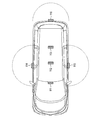
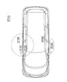
- FIG. 1 is a diagram showing the position of an antenna for smart entry provided in a vehicle.
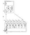
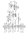
- FIG. 2 is a diagram showing a schematic configuration of the smart entry system according to the first embodiment of the present invention.
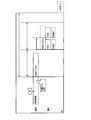
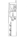
- FIG. 3 is a diagram showing signals and timings transmitted from each antenna by the in-vehicle device side microcomputer shown in FIG.
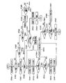
- FIG. 4 is a flowchart showing an operation procedure of the smart key side microcomputer shown in FIG.
- FIG. 5 is a diagram illustrating an area where the smart key may be located with respect to the vehicle when the vehicle is viewed from above.
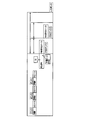
- FIG. 6 is a diagram illustrating signals and timings transmitted from each antenna by the vehicle-mounted device microcomputer according to the second embodiment of the present invention.
- FIG. 1 is a diagram showing the position of an antenna for smart entry provided in a vehicle.
- FIG. 2 is a diagram showing a schematic configuration of the smart entry system according to the first embodiment of the present invention.
- FIG. 3 is a diagram showing signals and timings transmitted from each antenna by
- FIG. 7 is a flowchart showing an operation procedure of the smart key side microcomputer according to the second embodiment of the present invention.
- FIG. 8 is a diagram illustrating an area where the smart key may be located with respect to the vehicle when the vehicle is viewed from above.
- FIG. 9 is a diagram illustrating signals and timings transmitted from each antenna by the in-vehicle device side microcomputer according to the third embodiment of the present invention.
- FIG. 10 is a flowchart showing an operation procedure of the smart key side microcomputer according to the third embodiment of the present invention.
- FIG. 11 is a diagram illustrating an area where the smart key may be located with respect to the vehicle when the vehicle is viewed from above.
- FIG. 1 is a diagram illustrating a position of an antenna for smart entry provided in a vehicle (sealed body).
- a vehicle interior antenna hereinafter referred to as “F antenna”
- M antenna vehicle interior antenna
- R antenna vehicle interior rear antenna
- FRDR antenna an outside driver side door handle antenna
- FRAS antenna an outside passenger side door handle antenna
- FRAS antenna an outside tail gate side antenna
- Three antennas 116 are provided.
- Embodiment 1 describes a case where the engine is prevented from starting when the smart key is present near the FRDR antenna or the FRAS antenna, that is, outside the vehicle. In the following description, it is assumed that the smart key exists near the FRAS antenna.
- FIG. 2 is a diagram showing a schematic configuration of the smart entry system 100 which is the short-range wireless communication system for vehicles according to the first embodiment.
- the smart entry system 100 includes an in-vehicle device 110 (first communication device) provided in a vehicle and a smart key 130 (second communication device) that is a portable device possessed by a user or the like.
- the on-vehicle device 110 includes a plurality of transmission antennas 111 to 116, transmission units 121 to 126, an RF reception antenna 117, an RF reception unit 127, and an on-vehicle device side microcomputer (also referred to as an antenna control unit) 128. .
- the plurality of transmission antennas 111 to 116 are an F antenna 111, an M antenna 112, an R antenna 113 provided inside the vehicle, an FRDR antenna 114, an FRAS antenna 115, and a TG antenna 116 provided outside the vehicle.
- the transmission units 121 to 126 are connected to the plurality of transmission antennas 111 to 116, respectively, perform transmission processing such as modulation and amplification on the signal output from the in-vehicle device side microcomputer 128, and send the signal subjected to transmission processing to Transmit from the transmitting antenna.
- the RF receiving antenna 117 receives an RF (Radio Frequency) signal transmitted from the smart key 130, and the RF receiving unit 127 performs reception processing such as demodulation on the signal received by the RF receiving antenna 117, and performs reception processing.
- the signal is output to the in-vehicle device side microcomputer 128.
- the on-board side microcomputer 128 controls which of the plurality of transmission antennas 111 to 116 is used, confirms the detection of the smart key 130, controls locking / unlocking of the vehicle door, and starts the engine. Or allow.
- the smart key 130 includes a reception antenna 131, a reception unit 132, a smart key side microcomputer 133, an RF transmission unit 134, and an RF transmission antenna 135.
- the reception antenna 131 receives signals transmitted from the antennas 111 to 116 of the vehicle-mounted device 110, and the reception unit 132 performs reception processing such as demodulation on the signal received by the reception antenna 131, and the signal subjected to reception processing. Is output to the smart key microcomputer 133.
- the smart key side microcomputer 133 measures RSSI (Received Signal Strength: Received Signal Strength) from the signal output from the receiving unit 132, performs a magnitude judgment (threshold judgment) between the measured RSSI and a predetermined threshold, and makes a judgment.
- RSSI Received Signal Strength: Received Signal Strength
- the RF response is output to the RF transmission unit 134 according to the result. The detailed operation of the smart key side microcomputer 133 will be described later.
- the RF transmission unit 134 performs transmission processing such as modulation and amplification on the RF response output from the smart key side microcomputer 133, and transmits the RF response subjected to the transmission processing from the RF transmission antenna 135 to the vehicle-mounted device 110.
- FIG. 3 is a diagram showing signals and timings transmitted from the antennas 111 to 116 by the in-vehicle device side microcomputer 128 shown in FIG.
- the onboard equipment-side microcomputer 128 sequentially transmits the call signal and the RSSI burst (first burst) from each of the F antenna 111, the M antenna 112, and the R antenna 113, and then the RSSI burst for FRDR and FRAS (second Burst).
- FIG. 3 shows a state when a signal is transmitted from the F antenna 111 as an example.
- the burst is a radio signal transmitted to measure the received signal strength.
- the call signal includes a signal for waking up the smart key 130 in the sleep state, an ID for authenticating the pair of the vehicle-mounted device 110 and the smart key 130, and a spare bit.
- the sleep state refers to a state in which a wake-up is received when a call signal is received. Details of the spare bit will be described later.
- the RSSI burst for F antenna is a continuous signal for the smart key 130 to measure RSSI (received signal strength) from the F antenna 111. From the call signal to the RSSI burst for the F antenna is an existing format.
- the RSSI burst for FRDR and the RSSI burst for FRAS are continuous signals for measuring RSSI from each antenna.
- FIG. 3 shows a case where a signal is transmitted from the F antenna 111, the same applies to transmission from the M antenna 112 and the R antenna 113.
- the smart key 130 Upon receiving such a signal, the smart key 130 measures RSSI from each RSSI burst, performs threshold determination between the measured RSSI and a predetermined threshold, and detects the position of the smart key 130 based on the threshold determination result. To do.
- the smart key 130 since the smart key 130 is assumed to be present near the FRAS antenna 115, the smart key 130 does not respond to a call from the F antenna 111.
- the spare bit is set to “0000” in the existing format, and instructs the determination of the RSSI burst for each antenna following the spare bit.
- the reserve bit “1000” is followed by an RSSI burst for FRDR and an RSSI burst for FRAS, followed by an instruction to measure these RSSIs. That is, “1000” is set in the spare bit included in the paging signal shown in FIG.
- FIG. 4 is a flowchart showing an operation procedure of the smart key side microcomputer 133.
- FIG. 5 is a diagram illustrating an area where the smart key may be located with respect to the vehicle when the vehicle is viewed from above.
- step ST201 the smart key side microcomputer 133 receives the call signal from the F antenna, and in step ST202, the smart key side microcomputer 133 determines whether or not the spare bit included in the call signal is “1000”.
- step ST202: NO the process proceeds to step ST203, and when the spare bit is “1000” (step ST202: YES), the process proceeds to step ST207.
- step ST203 the smart key side microcomputer 133 determines whether or not the reserved bit included in the calling signal is “0100”. When the reserved bit is not “0100” (step ST203: NO), the process proceeds to step ST204, and when the reserved bit is “0100” (step ST203: YES), the process proceeds to the flow of FIG.
- step ST204 the smart key side microcomputer 133 determines whether or not the reserved bit included in the calling signal is “0000”.
- the process proceeds to step ST219, and the smart key 130 transitions to the sleep state.
- the process proceeds to step ST205.
- step ST205 the smart key side microcomputer 133 measures the RSSI burst (first burst) for each antenna (here, for example, F antenna) in the vehicle, and in step ST206, the RSSI from the F antenna in the vehicle is a predetermined value. It is determined whether or not the threshold value F (threshold value indicating the effective reach range of the F antenna) is exceeded. If so (step ST206: YES), the process proceeds to step ST218, and if not exceeded (step ST206: NO). In step ST219, the smart key 130 transitions to the sleep state.
- the threshold value F threshold value indicating the effective reach range of the F antenna
- step ST207 the RSSI burst for each antenna (for example, F antenna in this case) in the vehicle is measured.
- the resolution of the AD converter hereinafter referred to as “ADC” is 10 bits, and the averaging count is 64 times.
- step ST208 the smart key side microcomputer 133 sets the ADC, sets the resolution to 10 bits, sets the averaging count to 4 times, and measures the RSSI burst (second burst) for FRDR in step ST209.
- step ST210 it is determined whether or not the RSSI from the F antenna in the vehicle exceeds a predetermined threshold F (step ST210: YES), the process proceeds to step ST211. If not (step ST210: NO), it is assumed that the smart key 130 is present at a position away from the vehicle shown in FIG. 5 (case 1), the process proceeds to step ST219, and the smart key 130 transitions to the sleep state.
- step ST211 it is determined whether or not the RSSI from the FRDR antenna outside the vehicle exceeds a predetermined threshold value b. If it exceeds (step ST211: YES), the process proceeds to step ST212, and if not (step ST211: NO) The process proceeds to step ST213.
- step ST212 the smart key side microcomputer 133 determines that the smart key 130 is present in the vicinity of the FRDR antenna (case 2) shown in FIG. 5, and moves to step ST219, where the smart key 130 shifts to the sleep state.
- step ST213 the smart key side microcomputer 133 sets the ADC, sets the resolution to 10 bits, sets the averaging count to 4 times, and measures the RSSI burst (third burst) for FRAS in step ST214.
- step ST215 the smart key side microcomputer 133 determines whether or not the RSSI from the F antenna in the vehicle exceeds a predetermined threshold value F (step ST215: YES), the process proceeds to step ST216 and does not exceed it. In this case (step ST215: NO), it is assumed that the smart key 130 exists at a position (case 1) away from the vehicle shown in FIG. 5, and the process proceeds to step ST219, and the smart key 130 transitions to the sleep state.
- step ST216 the smart key side microcomputer 133 determines whether or not the RSSI from the FRAS antenna outside the vehicle exceeds a predetermined threshold value b (the same value as the crosstalk threshold value), and if so (step ST216: YES). The process proceeds to step ST217, and if not exceeded (step ST216: NO), the process proceeds to step ST218.
- a predetermined threshold value b the same value as the crosstalk threshold value
- step ST217 the smart key side microcomputer 133 determines that the smart key 130 exists in the vicinity of the FRAS antenna (case 2 ') shown in FIG. 5, and moves to step ST219, where the smart key 130 transitions to the sleep state.
- step ST218 the smart key 130 is assumed to be present in the vehicle (case 4) shown in FIG. 5, and the smart key side microcomputer 133 transmits an RF response to the vehicle.
- the smart key side microcomputer 133 performs threshold determination between the RSSI measured from the RSSI burst for each antenna in the vehicle and the predetermined threshold F. If this RSSI exceeds the threshold F, there is a high possibility that the smart key 130 exists in the vehicle, but the possibility that the smart key 130 exists outside the vehicle due to the influence of crosstalk cannot be excluded.
- the threshold value is determined between the RSSI measured from the burst and the RSSI burst for FRAS and a predetermined threshold value b. If it is determined that the RSSI is larger than the threshold value b as a result of the threshold determination, it is understood that the smart key 130 exists outside the vehicle near the corresponding antenna. Therefore, smart key position detection can be realized at low cost without adding new hardware.
- each time the paging signal and the RSSI burst are transmitted from each antenna in the vehicle the RSSI burst for FRDR and FRAS is transmitted, and each RSSI burst received by the smart key is transmitted.
- the RSSI is measured, and a threshold determination between the measured RSSI and a predetermined threshold is performed. Thereby, the position of the smart key can be accurately detected based on the result of the threshold determination. For this reason, it is possible to prevent the engine from starting when the smart key exists near the FRDR antenna or the FRAS antenna, that is, outside the vehicle.
- the first burst, the second burst, and the third burst are arbitrarily selected from the six antennas, that is, the F antenna 111, the M antenna 112, the R antenna 113, the FRDR antenna 114, the FRAS antenna 115, and the TG antenna 116. It may be a burst transmitted from three antennas.
- Embodiment 2 In the second embodiment, a case will be described in which entry from the other door is prevented when a smart key that is a portable device exists near one door antenna (FRDR antenna or FRAS antenna). In the following description, it is assumed that the smart key exists near the FRAS antenna.
- the configuration of the smart entry system which is the vehicle short-range wireless communication system of the second embodiment, is the same as the configuration shown in FIG. 2 of the first embodiment. Therefore, FIG. 2 is incorporated as needed. explain.
- FIG. 6 is a diagram showing signals and timings transmitted from each antenna by the vehicle-mounted device-side microcomputer 128 according to the second embodiment.
- the vehicle-mounted device 110 After sequentially transmitting the standby instruction signal and the RSSI burst from each of the F antenna 111, the M antenna 112, and the R antenna 113, the call signal and the RSSI burst for FRDR are transmitted from the FRDR antenna 114, The FRAS RSSI burst is transmitted from the FRAS antenna 115.
- the format from the standby instruction signal of the F antenna 111 to the RSSI burst for FRDR is an existing format.
- the smart key 130 that has received such a signal maintains a standby state when receiving a standby instruction signal from each antenna in the vehicle.
- the standby state means that the call signal is ignored even if the call signal is received.
- the smart key 130 measures RSSI from the RSSI burst for FRDR and the RSSI burst for FRAS, and performs threshold judgment between the measured RSSI and a predetermined threshold. The position of the key 130 is detected.
- the smart key 130 since the smart key 130 is assumed to be present near the FRAS antenna 115, the smart key 130 does not respond to a call from the FRDR antenna 114.
- spare bits included in the call signal shown in FIG. 6 will be described.
- the spare bit “0100” is followed by the RSSI burst for FRAS in the existing format, and an instruction to measure this RSSI is assigned. That is, “0100” is set in the spare bit included in the paging signal shown in FIG.
- FIG. 7 is a flowchart showing an operation procedure of the smart key side microcomputer 133.
- FIG. 8 is a diagram illustrating an area where the smart key may be located with respect to the vehicle when the vehicle is viewed from above.
- step ST301 the smart key side microcomputer 133 receives the call signal from the FRDR antenna 114, and in step ST302, determines whether or not the spare bit included in the call signal is “0100”.
- step ST302: NO the process proceeds to step ST303, and when the spare bit is “0100” (step ST302: YES), the process proceeds to step ST306.
- step ST303 the smart key side microcomputer 133 determines whether or not the spare bit included in the calling signal is “0000”. When the spare bit is not “0000” (step ST303: NO), the process proceeds to step ST317, and the smart key 130 transitions to the sleep state. On the other hand, when the spare bit is “0000” (step ST303: YES), the process proceeds to step ST304.
- step ST304 the smart key side microcomputer 133 measures the RSSI burst for each antenna (here, for example, F antenna) in the vehicle, and in step ST305, the RSSI from the F antenna in the vehicle has a predetermined threshold value F (F antenna). If it exceeds the threshold (step ST305: YES), the process proceeds to step ST314. If not (step ST305: NO), the process proceeds to step ST317. Then, the smart key 130 transitions to the sleep state.
- F antenna a predetermined threshold value F
- step ST302 If the spare bit is “0100” in step ST302 (step ST302: YES), the FRDR RSSI burst is measured in step ST306. At this time, the ADC resolution is 10 bits and the averaging count is 64 times.
- step ST307 the smart key side microcomputer 133 determines whether or not it is waiting. If it is waiting (step ST307: YES), the process proceeds to step ST308, and if it is not waiting (step ST307: Step ST307: NO), the process proceeds to step ST310.
- step ST308 the smart key side microcomputer 133 determines a threshold value whether or not the RSSI for FRDR exceeds a predetermined crosstalk threshold value. If it exceeds (YES in step ST308), the standby state is set in step ST309. If it does not exceed (NO in step ST308), the process proceeds to step ST316. In ST309, it is assumed that smart key 130 exists near FRDR antenna 114 (case 3) shown in FIG.
- step ST310 the smart key side microcomputer 133 measures the RSSI burst for FRAS, and in step ST311, it is determined whether or not the RSSI for FRDR exceeds a predetermined threshold value, and if so (step ST311: YES). The process proceeds to step ST312, and if not exceeding (step ST311: NO), it is assumed that the smart key 130 exists at a position (case 1) away from the vehicle shown in FIG. 8, and the process proceeds to step ST317.
- step ST312 the smart key side microcomputer 133 determines whether or not the RSSI for FRDR exceeds the RSSI for FRAS (step ST312: YES), the process proceeds to step ST313. (Step ST312: NO), the process proceeds to ST315, and it is assumed that the smart key 130 is present near the FRAS antenna 115 (case 5) shown in FIG. 8, and the process proceeds to step ST317.
- step ST313 the smart key side microcomputer 133 determines that the smart key 130 exists near the FRDR antenna.
- step ST314 the smart key 130 exists near the FRDR antenna 114 shown in FIG. 8 (case 3). An RF response is transmitted to the vehicle.
- step ST315 the smart key side microcomputer 133 determines that the smart key 130 exists in the vicinity of the FRAS antenna, moves to step ST317, and the smart key 130 shifts to the sleep state.
- step ST316 it is assumed that the smart key 130 exists in the vehicle (case 4 or case 4 ') shown in FIG. 8, and the smart key side microcomputer 133 continues to wait until the end of the standby.
- step ST317 the smart key 130 is Transition to the sleep state.
- the smart key side microcomputer 133 performs threshold determination between the RSSI measured from the RSSI burst for FRDR and a predetermined threshold. If this RSSI exceeds the threshold value, there is a high possibility that the smart key 130 exists near the FRDR antenna 114, but the possibility that the smart key 130 exists near the FRAS antenna 115 due to the influence of crosstalk cannot be excluded. Determines the size of RSSIs measured from the RSSI burst for FRDR and the RSSI burst for FRAS. As a result of this determination, it can be seen that the smart key 130 exists near the antenna on the side determined to have a large RSSI.
- the call signal and the FRDR RSSI burst are transmitted from the FRDR antenna, the FRAS RSSI burst is transmitted from the FRAS antenna, and the RSSI is received from each RSSI burst received by the smart key. Measure and perform size judgment between RSSIs. Accordingly, the position of the smart key can be accurately detected according to the result of the size determination, and entry from the other door can be prevented when the smart key exists near one door antenna.
- FIG. 9 is a diagram showing signals and timings transmitted from each antenna by the vehicle-mounted device-side microcomputer 128 according to the third embodiment.
- the vehicle-mounted device 110 After sequentially transmitting the standby instruction signal and the RSSI burst from each of the F antenna 111, the M antenna 112, and the R antenna 113, the paging signal and the TG RSSI burst are transmitted from the TG antenna 116.
- the FRDR antenna 114 transmits the FRDR RSSI burst
- the FRAS antenna 115 transmits the FRAS RSSI burst.
- the format from the standby instruction signal of the F antenna 111 to the RSSI burst for TG is an existing format.
- the smart key 130 Upon receiving such a signal, the smart key 130 maintains a standby state when receiving a standby instruction signal from each antenna in the vehicle, and receives a paging signal from the TG antenna 116, and receives a TG RSSI burst or FRDR RSSI.
- the RSSI is measured from each of the burst and the RSSI burst for FRAS, and the threshold determination between the measured RSSI and a predetermined threshold is performed to detect the position of the smart key 130.
- the smart key 130 since the smart key 130 is assumed to be present near the FRAS antenna 115, the smart key 130 does not respond to a call from the TG antenna 116.
- the spare bits included in the paging signal shown in FIG. 9 are the same as in the first embodiment, and the spare bit “1000” is followed by the RSSI burst for FRDA and the RSSI burst for FRAS. Instructions for measuring these RSSIs are assigned.
- FIG. 10 is a flowchart showing an operation procedure of the smart key side microcomputer 133.
- FIG. 11 is a diagram illustrating an area where the smart key may be located with respect to the vehicle when the vehicle is viewed from above.
- step ST401 the smart key side microcomputer 133 receives the call signal from the TG antenna, and in step ST402, determines whether or not the spare bit included in the call signal is “1000”. When the spare bit is not “1000” (step ST402: NO), the process proceeds to step ST403.
- step ST403 the smart key side microcomputer 133 determines whether or not the spare bit included in the calling signal is “0100”. When the spare bit is not “0100” (step ST403: NO), the process proceeds to step ST404, and when the spare bit is “0100” (step ST403: YES), the process proceeds to the flow of FIG.
- step ST404 the smart key side microcomputer 133 determines whether or not the spare bit included in the calling signal is “0000”. When the spare bit is not “0000” (step ST404: NO), the process proceeds to step ST423, and the smart key 130 transitions to the sleep state. On the other hand, when the spare bit is “0000” (step ST404: YES), the process proceeds to step ST405.
- step ST405 the smart key side microcomputer 133 measures the RSSI burst for TG, and in step ST406, it is determined whether or not the RSSI from the TG antenna exceeds a predetermined threshold TG (threshold indicating the effective range of the TG antenna). If determined and exceeded (step ST406: YES), the process proceeds to step ST421. If not exceeded (step ST406: NO), the process proceeds to step ST423, and the smart key 130 transitions to the sleep state.
- TG threshold indicating the effective range of the TG antenna
- step ST402 If the spare bit is “1000” in step ST402 (step ST402: YES), the TG RSSI burst is measured in step ST407. At this time, the ADC resolution is 10 bits and the averaging count is 64 times.
- step ST408 the smart key side microcomputer 133 determines whether or not it is on standby. If it is on standby (step ST408: YES), the process proceeds to step ST409, and if it is not on standby (step ST408: Step ST408: NO), the process proceeds to step ST411.
- step ST409 the smart key side microcomputer 133 determines whether or not the TG RSSI exceeds a predetermined crosstalk threshold (step ST409: YES), and cancels the standby state in step ST410. If not exceeding (step ST409: NO), the process proceeds to step ST422. In ST410, it is assumed that smart key 130 exists near TG antenna (case 5), FRDR antenna (case 2), or FRAS antenna (case 2 ') shown in FIG.
- step ST411 the smart key side microcomputer 133 sets ADC, sets the resolution to 10 bits, sets the averaging count to 4 times, and measures the RSSI burst for FRDR in step ST412.
- step ST413 the smart key side microcomputer 133 determines whether or not the RSSI for TG exceeds a predetermined threshold TG (step ST413: YES), and proceeds to step ST414. (Step ST413: NO), it is assumed that the smart key 130 exists at a position (case 1) away from the vehicle shown in FIG. 11, and the process proceeds to Step ST423.
- step ST414 the smart key side microcomputer 133 determines whether or not the RSSI for FRDR exceeds a predetermined threshold value b (step ST414: YES), and proceeds to step ST415. (Step ST414: NO), the process proceeds to step ST416.
- step ST415 the smart key side microcomputer 133 determines that the smart key 130 exists in the vicinity of the FRDR antenna (case 2), moves to step ST423, and the smart key 130 shifts to the sleep state.
- step ST416 the smart key side microcomputer 133 sets the ADC, sets the resolution to 10 bits, sets the averaging count to 4 times, and measures the RSSI burst for FRAS in step ST417.
- step ST418 the smart key side microcomputer 133 determines whether or not the RSSI for TG exceeds a predetermined threshold value TG (step ST418: YES), the process proceeds to step ST419. (Step ST418: NO), the process proceeds to step ST423, and the smart key 130 transitions to the sleep state.
- step ST419 the smart key side microcomputer 133 determines whether or not the RSSI for FRAS exceeds a predetermined threshold value b (step ST419: YES), the process proceeds to step ST420. (Step ST419: NO), the process proceeds to step ST421.
- step ST420 the smart key side microcomputer 133 determines that the smart key 130 exists in the vicinity of the FRAS antenna 115 (case 2 '), shifts to step ST423, and the smart key 130 shifts to the sleep state.
- step ST421 it is assumed that the smart key 130 exists near the TG antenna (case 4 or case 5) shown in FIG. 11, and the smart key side microcomputer 133 transmits an RF response to the vehicle.
- step ST422 it is assumed that the smart key 130 exists in the vehicle (case 3 or case 3 ′) shown in FIG. 11, and the smart key side microcomputer 133 continues to wait until the end of the standby.
- step ST423 the smart key 130 is Transition to the sleep state.
- the smart key side microcomputer 133 performs threshold determination between the RSSI measured from the RSSI burst for TG and the predetermined threshold TG. If this RSSI exceeds the threshold value TG, there is a high possibility that the smart key 130 exists near the tail gate, but the possibility that it exists in another position due to the influence of crosstalk cannot be excluded. Then, the threshold value determination between the RSSI measured from the FRDR RSSI burst and the RSSI burst for FRAS and the predetermined threshold value b is performed. If it is determined that the RSSI is larger than the threshold value b as a result of the threshold determination, it is understood that the smart key 130 exists outside the vehicle near the corresponding antenna.
- the paging signal and the RSSI burst for TG are transmitted from the TG antenna, the RSSI burst for FRDR and FRAS is further transmitted, and the RSSI is received from each RSSI burst received by the smart key. Measure and perform threshold determination between the measured RSSI and a predetermined threshold. As a result, the position of the smart key can be accurately detected based on the result of the threshold determination, and when the smart key is present near one door antenna (FRDR antenna or FRAS antenna), the tailgate is unlocked. Can be prevented.
- the standby instruction signal from each antenna in the vehicle leaks from the FRDR antenna 114 or the FRAS antenna 115, the smart key 130 located in the vicinity of the FRAS antenna 115 enters the standby state, and further, the calling signal from the TG antenna 116 becomes the FRDR antenna. 114 or the FRAS antenna 115, the present embodiment can be applied even when the standby state of the smart key 130 is released.
- the name “smart key” has been described, but the smart key is also referred to as an FOB key, an electronic key, a portable key, a badge, or the like.
- the smart key side microcomputer 133 is described as performing RSSI measurement, threshold value determination, and the like.
- the smart key side microcomputer 133 measures RSSI, and the measured RSSI is used as the in-vehicle device side microcomputer 128.
- the vehicle-mounted device-side microcomputer 128 may perform threshold determination or the like.
- the vehicle short-range wireless communication system according to the present invention is useful for detecting the position of the smart key.
- Smart entry system (Vehicle short-range wireless communication system) 110 On-vehicle device (first communication device) 111 F antenna 112 M antenna 113 R antenna 114 FRDR antenna 115 FRAS antenna 116 TG antenna 117 RF receiving antenna 121-126 Transmitting unit 127 RF receiving unit 128 On-vehicle device side microcomputer 130 Smart key (portable device, second communication device) 131 reception antenna 132 reception unit 133 smart key side microcomputer 134 RF transmission unit 135 RF transmission antenna
Landscapes
- Engineering & Computer Science (AREA)
- Computer Networks & Wireless Communication (AREA)
- Mechanical Engineering (AREA)
- Physics & Mathematics (AREA)
- General Physics & Mathematics (AREA)
- Signal Processing (AREA)
- Lock And Its Accessories (AREA)
- Radar Systems Or Details Thereof (AREA)
- Selective Calling Equipment (AREA)
Priority Applications (1)
| Application Number | Priority Date | Filing Date | Title |
|---|---|---|---|
| US15/074,012 US9813846B2 (en) | 2013-10-02 | 2016-03-18 | Short-distance radio communication system for vehicle |
Applications Claiming Priority (2)
| Application Number | Priority Date | Filing Date | Title |
|---|---|---|---|
| JP2013-207251 | 2013-10-02 | ||
| JP2013207251A JP2015072162A (ja) | 2013-10-02 | 2013-10-02 | 車両用近距離無線通信システム |
Related Child Applications (1)
| Application Number | Title | Priority Date | Filing Date |
|---|---|---|---|
| US15/074,012 Continuation US9813846B2 (en) | 2013-10-02 | 2016-03-18 | Short-distance radio communication system for vehicle |
Publications (1)
| Publication Number | Publication Date |
|---|---|
| WO2015049856A1 true WO2015049856A1 (ja) | 2015-04-09 |
Family
ID=52778461
Family Applications (1)
| Application Number | Title | Priority Date | Filing Date |
|---|---|---|---|
| PCT/JP2014/004968 Ceased WO2015049856A1 (ja) | 2013-10-02 | 2014-09-29 | 車両用近距離無線通信システム |
Country Status (3)
| Country | Link |
|---|---|
| US (1) | US9813846B2 (enExample) |
| JP (1) | JP2015072162A (enExample) |
| WO (1) | WO2015049856A1 (enExample) |
Cited By (1)
| Publication number | Priority date | Publication date | Assignee | Title |
|---|---|---|---|---|
| CN111918797A (zh) * | 2018-02-01 | 2020-11-10 | 斯特拉泰克安全公司 | 用于为车辆提供基于蓝牙的被动进入和被动启动(peps)的方法和系统 |
Families Citing this family (6)
| Publication number | Priority date | Publication date | Assignee | Title |
|---|---|---|---|---|
| JP6274031B2 (ja) * | 2014-06-26 | 2018-02-07 | 株式会社オートネットワーク技術研究所 | 車両用通信システム、車載機、携帯機及びコンピュータプログラム |
| DE102015217413B4 (de) * | 2015-09-11 | 2017-09-28 | Continental Automotive Gmbh | Verfahren und Anordnung zum Lokalisieren einer tragbaren Funkeinheit |
| JP6693208B2 (ja) * | 2016-03-23 | 2020-05-13 | トヨタ自動車株式会社 | スマートキーシステム |
| JP7127503B2 (ja) * | 2018-11-14 | 2022-08-30 | 株式会社デンソー | 送信制御装置、携帯機、車両システム、送信制御方法、制御方法、及び制御プログラム |
| JP7127502B2 (ja) | 2018-11-14 | 2022-08-30 | 株式会社デンソー | 送信制御装置、車両システム、送信制御方法、及び制御プログラム |
| CN110866240A (zh) * | 2019-11-12 | 2020-03-06 | 北京握奇智能科技有限公司 | 智能密码钥匙调用方法和系统 |
Citations (4)
| Publication number | Priority date | Publication date | Assignee | Title |
|---|---|---|---|---|
| JP2004263447A (ja) * | 2003-03-03 | 2004-09-24 | Omron Corp | 車両用リモートコントロールシステム |
| JP2007070953A (ja) * | 2005-09-09 | 2007-03-22 | Alps Electric Co Ltd | キーレスエントリー装置 |
| JP2010216142A (ja) * | 2009-03-17 | 2010-09-30 | Omron Corp | パッシブエントリーシステム、及び通信方法 |
| JP2011144624A (ja) * | 2009-12-18 | 2011-07-28 | Tokai Rika Co Ltd | 通信端末位置判定装置 |
Family Cites Families (6)
| Publication number | Priority date | Publication date | Assignee | Title |
|---|---|---|---|---|
| FR2843240B1 (fr) | 2002-08-05 | 2008-03-21 | Siemens Vdo Automotive | Procede de commande d'antennes d'un systeme mains libres d'un vehicule automobile et dispositif correspondant |
| JP4485984B2 (ja) | 2005-04-01 | 2010-06-23 | 株式会社東海理化電機製作所 | 通信制御装置 |
| JP5027083B2 (ja) * | 2008-09-04 | 2012-09-19 | 株式会社東海理化電機製作所 | 位置判定装置 |
| US8284020B2 (en) * | 2009-12-22 | 2012-10-09 | Lear Corporation | Passive entry system and method for a vehicle |
| JP5685073B2 (ja) * | 2010-12-17 | 2015-03-18 | 株式会社東海理化電機製作所 | 電子キーシステム |
| US20140368313A1 (en) * | 2013-06-14 | 2014-12-18 | Texas Instruments Incorporated | Vehicle keyfob with accelerometer to extend battery life |
-
2013
- 2013-10-02 JP JP2013207251A patent/JP2015072162A/ja active Pending
-
2014
- 2014-09-29 WO PCT/JP2014/004968 patent/WO2015049856A1/ja not_active Ceased
-
2016
- 2016-03-18 US US15/074,012 patent/US9813846B2/en active Active
Patent Citations (4)
| Publication number | Priority date | Publication date | Assignee | Title |
|---|---|---|---|---|
| JP2004263447A (ja) * | 2003-03-03 | 2004-09-24 | Omron Corp | 車両用リモートコントロールシステム |
| JP2007070953A (ja) * | 2005-09-09 | 2007-03-22 | Alps Electric Co Ltd | キーレスエントリー装置 |
| JP2010216142A (ja) * | 2009-03-17 | 2010-09-30 | Omron Corp | パッシブエントリーシステム、及び通信方法 |
| JP2011144624A (ja) * | 2009-12-18 | 2011-07-28 | Tokai Rika Co Ltd | 通信端末位置判定装置 |
Cited By (2)
| Publication number | Priority date | Publication date | Assignee | Title |
|---|---|---|---|---|
| CN111918797A (zh) * | 2018-02-01 | 2020-11-10 | 斯特拉泰克安全公司 | 用于为车辆提供基于蓝牙的被动进入和被动启动(peps)的方法和系统 |
| CN111918797B (zh) * | 2018-02-01 | 2022-04-26 | 斯特拉泰克安全公司 | 用于为车辆提供基于蓝牙的被动进入和被动启动(peps)的方法和系统 |
Also Published As
| Publication number | Publication date |
|---|---|
| JP2015072162A (ja) | 2015-04-16 |
| US9813846B2 (en) | 2017-11-07 |
| US20160205498A1 (en) | 2016-07-14 |
Similar Documents
| Publication | Publication Date | Title |
|---|---|---|
| US11214232B2 (en) | Methods and systems for providing Bluetooth-based passive entry and passive start (PEPS) for a vehicle | |
| JP6340716B2 (ja) | 車両用近距離無線通信システム、携帯機及び車載器 | |
| WO2015049856A1 (ja) | 車両用近距離無線通信システム | |
| JP5615326B2 (ja) | 携帯機の位置判定システム、携帯機の位置判定方法、携帯機の位置判定装置 | |
| CN104943658B (zh) | 电子钥匙系统 | |
| JP4673251B2 (ja) | キーレスエントリー装置 | |
| JP4362136B2 (ja) | 車両用電子キー装置 | |
| JP2013100672A (ja) | 車載通信システム、車載通信装置、および位置判定方法 | |
| WO2016110913A1 (ja) | 通信システム、位置判定方法 | |
| JP2012107377A (ja) | 車両用スマートキーの携帯機探索装置、及び携帯機探索方法 | |
| JP2015113643A (ja) | キーレスエントリーシステム | |
| WO2014017056A1 (ja) | 車載機器制御システム | |
| CN107444340A (zh) | 无线通信系统 | |
| JP2020070676A (ja) | 通信装置 | |
| JP5619223B1 (ja) | 無線通信システム | |
| WO2018221475A1 (ja) | 携帯機 | |
| JP2011259386A (ja) | 無線通信システム | |
| US11243303B2 (en) | Portable terminal position detection apparatus | |
| JP4384946B2 (ja) | パッシブキーレスエントリー装置 | |
| JP2021000894A (ja) | 車両盗難防止システムおよび車載器型盗難防止装置 | |
| JP2018071157A (ja) | 車両用通信システム及び携帯機 | |
| JP4633579B2 (ja) | タイヤ位置検出装置 | |
| JP2006225868A (ja) | 自動暗号照合確認施解錠制御装置 | |
| JP5610288B2 (ja) | 車両用施錠システム | |
| JP2008127877A (ja) | 車両用キーレス装置 |
Legal Events
| Date | Code | Title | Description |
|---|---|---|---|
| 121 | Ep: the epo has been informed by wipo that ep was designated in this application |
Ref document number: 14850831 Country of ref document: EP Kind code of ref document: A1 |
|
| NENP | Non-entry into the national phase |
Ref country code: DE |
|
| 122 | Ep: pct application non-entry in european phase |
Ref document number: 14850831 Country of ref document: EP Kind code of ref document: A1 |