WO2015033501A1 - 映像受信装置、映像認識方法および付加情報表示システム - Google Patents
映像受信装置、映像認識方法および付加情報表示システム Download PDFInfo
- Publication number
- WO2015033501A1 WO2015033501A1 PCT/JP2014/003548 JP2014003548W WO2015033501A1 WO 2015033501 A1 WO2015033501 A1 WO 2015033501A1 JP 2014003548 W JP2014003548 W JP 2014003548W WO 2015033501 A1 WO2015033501 A1 WO 2015033501A1
- Authority
- WO
- WIPO (PCT)
- Prior art keywords
- video
- information
- recognition
- video recognition
- content
- Prior art date
Links
Images


Classifications
-
- H—ELECTRICITY
- H04—ELECTRIC COMMUNICATION TECHNIQUE
- H04N—PICTORIAL COMMUNICATION, e.g. TELEVISION
- H04N21/00—Selective content distribution, e.g. interactive television or video on demand [VOD]
- H04N21/40—Client devices specifically adapted for the reception of or interaction with content, e.g. set-top-box [STB]; Operations thereof
- H04N21/43—Processing of content or additional data, e.g. demultiplexing additional data from a digital video stream; Elementary client operations, e.g. monitoring of home network or synchronising decoder's clock; Client middleware
- H04N21/431—Generation of visual interfaces for content selection or interaction; Content or additional data rendering
- H04N21/4312—Generation of visual interfaces for content selection or interaction; Content or additional data rendering involving specific graphical features, e.g. screen layout, special fonts or colors, blinking icons, highlights or animations
- H04N21/4316—Generation of visual interfaces for content selection or interaction; Content or additional data rendering involving specific graphical features, e.g. screen layout, special fonts or colors, blinking icons, highlights or animations for displaying supplemental content in a region of the screen, e.g. an advertisement in a separate window
-
- G—PHYSICS
- G06—COMPUTING; CALCULATING OR COUNTING
- G06V—IMAGE OR VIDEO RECOGNITION OR UNDERSTANDING
- G06V20/00—Scenes; Scene-specific elements
- G06V20/40—Scenes; Scene-specific elements in video content
-
- G—PHYSICS
- G06—COMPUTING; CALCULATING OR COUNTING
- G06V—IMAGE OR VIDEO RECOGNITION OR UNDERSTANDING
- G06V20/00—Scenes; Scene-specific elements
- G06V20/40—Scenes; Scene-specific elements in video content
- G06V20/46—Extracting features or characteristics from the video content, e.g. video fingerprints, representative shots or key frames
-
- H—ELECTRICITY
- H04—ELECTRIC COMMUNICATION TECHNIQUE
- H04N—PICTORIAL COMMUNICATION, e.g. TELEVISION
- H04N21/00—Selective content distribution, e.g. interactive television or video on demand [VOD]
- H04N21/20—Servers specifically adapted for the distribution of content, e.g. VOD servers; Operations thereof
- H04N21/23—Processing of content or additional data; Elementary server operations; Server middleware
- H04N21/234—Processing of video elementary streams, e.g. splicing of video streams, manipulating MPEG-4 scene graphs
- H04N21/23424—Processing of video elementary streams, e.g. splicing of video streams, manipulating MPEG-4 scene graphs involving splicing one content stream with another content stream, e.g. for inserting or substituting an advertisement
-
- H—ELECTRICITY
- H04—ELECTRIC COMMUNICATION TECHNIQUE
- H04N—PICTORIAL COMMUNICATION, e.g. TELEVISION
- H04N21/00—Selective content distribution, e.g. interactive television or video on demand [VOD]
- H04N21/40—Client devices specifically adapted for the reception of or interaction with content, e.g. set-top-box [STB]; Operations thereof
- H04N21/47—End-user applications
- H04N21/472—End-user interface for requesting content, additional data or services; End-user interface for interacting with content, e.g. for content reservation or setting reminders, for requesting event notification, for manipulating displayed content
- H04N21/4722—End-user interface for requesting content, additional data or services; End-user interface for interacting with content, e.g. for content reservation or setting reminders, for requesting event notification, for manipulating displayed content for requesting additional data associated with the content
- H04N21/4725—End-user interface for requesting content, additional data or services; End-user interface for interacting with content, e.g. for content reservation or setting reminders, for requesting event notification, for manipulating displayed content for requesting additional data associated with the content using interactive regions of the image, e.g. hot spots
-
- H—ELECTRICITY
- H04—ELECTRIC COMMUNICATION TECHNIQUE
- H04N—PICTORIAL COMMUNICATION, e.g. TELEVISION
- H04N21/00—Selective content distribution, e.g. interactive television or video on demand [VOD]
- H04N21/40—Client devices specifically adapted for the reception of or interaction with content, e.g. set-top-box [STB]; Operations thereof
- H04N21/47—End-user applications
- H04N21/482—End-user interface for program selection
- H04N21/4828—End-user interface for program selection for searching program descriptors
-
- H—ELECTRICITY
- H04—ELECTRIC COMMUNICATION TECHNIQUE
- H04N—PICTORIAL COMMUNICATION, e.g. TELEVISION
- H04N21/00—Selective content distribution, e.g. interactive television or video on demand [VOD]
- H04N21/40—Client devices specifically adapted for the reception of or interaction with content, e.g. set-top-box [STB]; Operations thereof
- H04N21/47—End-user applications
- H04N21/485—End-user interface for client configuration
- H04N21/4856—End-user interface for client configuration for language selection, e.g. for the menu or subtitles
-
- H—ELECTRICITY
- H04—ELECTRIC COMMUNICATION TECHNIQUE
- H04N—PICTORIAL COMMUNICATION, e.g. TELEVISION
- H04N21/00—Selective content distribution, e.g. interactive television or video on demand [VOD]
- H04N21/40—Client devices specifically adapted for the reception of or interaction with content, e.g. set-top-box [STB]; Operations thereof
- H04N21/47—End-user applications
- H04N21/488—Data services, e.g. news ticker
- H04N21/4884—Data services, e.g. news ticker for displaying subtitles
-
- H—ELECTRICITY
- H04—ELECTRIC COMMUNICATION TECHNIQUE
- H04N—PICTORIAL COMMUNICATION, e.g. TELEVISION
- H04N21/00—Selective content distribution, e.g. interactive television or video on demand [VOD]
- H04N21/40—Client devices specifically adapted for the reception of or interaction with content, e.g. set-top-box [STB]; Operations thereof
- H04N21/47—End-user applications
- H04N21/488—Data services, e.g. news ticker
- H04N21/4888—Data services, e.g. news ticker for displaying teletext characters
-
- H—ELECTRICITY
- H04—ELECTRIC COMMUNICATION TECHNIQUE
- H04N—PICTORIAL COMMUNICATION, e.g. TELEVISION
- H04N21/00—Selective content distribution, e.g. interactive television or video on demand [VOD]
- H04N21/80—Generation or processing of content or additional data by content creator independently of the distribution process; Content per se
- H04N21/81—Monomedia components thereof
- H04N21/8126—Monomedia components thereof involving additional data, e.g. news, sports, stocks, weather forecasts
- H04N21/8133—Monomedia components thereof involving additional data, e.g. news, sports, stocks, weather forecasts specifically related to the content, e.g. biography of the actors in a movie, detailed information about an article seen in a video program
-
- H—ELECTRICITY
- H04—ELECTRIC COMMUNICATION TECHNIQUE
- H04N—PICTORIAL COMMUNICATION, e.g. TELEVISION
- H04N21/00—Selective content distribution, e.g. interactive television or video on demand [VOD]
- H04N21/80—Generation or processing of content or additional data by content creator independently of the distribution process; Content per se
- H04N21/83—Generation or processing of protective or descriptive data associated with content; Content structuring
- H04N21/835—Generation of protective data, e.g. certificates
- H04N21/8352—Generation of protective data, e.g. certificates involving content or source identification data, e.g. Unique Material Identifier [UMID]
-
- H—ELECTRICITY
- H04—ELECTRIC COMMUNICATION TECHNIQUE
- H04N—PICTORIAL COMMUNICATION, e.g. TELEVISION
- H04N21/00—Selective content distribution, e.g. interactive television or video on demand [VOD]
- H04N21/80—Generation or processing of content or additional data by content creator independently of the distribution process; Content per se
- H04N21/83—Generation or processing of protective or descriptive data associated with content; Content structuring
- H04N21/835—Generation of protective data, e.g. certificates
- H04N21/8358—Generation of protective data, e.g. certificates involving watermark
-
- H—ELECTRICITY
- H04—ELECTRIC COMMUNICATION TECHNIQUE
- H04N—PICTORIAL COMMUNICATION, e.g. TELEVISION
- H04N21/00—Selective content distribution, e.g. interactive television or video on demand [VOD]
- H04N21/80—Generation or processing of content or additional data by content creator independently of the distribution process; Content per se
- H04N21/85—Assembly of content; Generation of multimedia applications
- H04N21/858—Linking data to content, e.g. by linking an URL to a video object, by creating a hotspot
- H04N21/8586—Linking data to content, e.g. by linking an URL to a video object, by creating a hotspot by using a URL
-
- H—ELECTRICITY
- H04—ELECTRIC COMMUNICATION TECHNIQUE
- H04N—PICTORIAL COMMUNICATION, e.g. TELEVISION
- H04N5/00—Details of television systems
- H04N5/222—Studio circuitry; Studio devices; Studio equipment
- H04N5/262—Studio circuits, e.g. for mixing, switching-over, change of character of image, other special effects ; Cameras specially adapted for the electronic generation of special effects
- H04N5/265—Mixing
-
- H—ELECTRICITY
- H04—ELECTRIC COMMUNICATION TECHNIQUE
- H04N—PICTORIAL COMMUNICATION, e.g. TELEVISION
- H04N21/00—Selective content distribution, e.g. interactive television or video on demand [VOD]
- H04N21/20—Servers specifically adapted for the distribution of content, e.g. VOD servers; Operations thereof
- H04N21/23—Processing of content or additional data; Elementary server operations; Server middleware
- H04N21/237—Communication with additional data server
-
- H—ELECTRICITY
- H04—ELECTRIC COMMUNICATION TECHNIQUE
- H04N—PICTORIAL COMMUNICATION, e.g. TELEVISION
- H04N21/00—Selective content distribution, e.g. interactive television or video on demand [VOD]
- H04N21/40—Client devices specifically adapted for the reception of or interaction with content, e.g. set-top-box [STB]; Operations thereof
- H04N21/43—Processing of content or additional data, e.g. demultiplexing additional data from a digital video stream; Elementary client operations, e.g. monitoring of home network or synchronising decoder's clock; Client middleware
- H04N21/437—Interfacing the upstream path of the transmission network, e.g. for transmitting client requests to a VOD server
Definitions
- This disclosure relates to a video receiving apparatus that acquires additional information related to a video signal input from the outside and superimposes the additional information on the video signal.
- Patent Document 1 discloses a data processing system.
- a client device transmits video data through a network to a server device that is a video recognition device, and requests video recognition processing.
- the server device performs video recognition based on the received video data, and transmits the video recognition result to the client device through the network.
- This disclosure provides a video receiving apparatus, a video recognition method, and an additional information display system that are effective for acquiring additional information related to an externally input video signal and superimposing the acquired additional information on the video signal.
- the video reception device of the present disclosure is configured to be able to transmit and receive data via a communication network, and includes an input unit, a video extraction unit, a video recognition area setting unit, a control unit, and an additional information display control unit.
- the input unit is configured to input a video signal output from a video transmission device installed outside and content-related information including feature information indicating characteristics of the video signal.
- the video extraction unit is configured to extract a partial video for video recognition processing from the video signal.
- the video recognition area setting unit is configured to set the video recognition area for the partial video based on the feature information included in the content related information.
- the control unit transmits content recognition information to a video recognition device connected to the communication network, requests video recognition processing, acquires the result of the video recognition processing from the video recognition device, and adds the result of the video recognition processing to the result of the video recognition processing. It is configured to perform control for acquiring the additional information based on the additional information distribution apparatus connected to the communication network.
- the additional information display control unit is configured to generate content recognition information in the video recognition area of the partial video.
- the video recognition method of the present disclosure is a video recognition method in a video reception device configured to be able to transmit and receive data via a communication network, and a partial video for video recognition processing is obtained from a video signal input from the outside.
- the additional information display system of the present disclosure includes a video reception device, a video recognition device, and an additional information distribution device configured to be able to transmit and receive data to and from each other via a communication network.
- the video reception device includes an input unit, a video extraction unit, a video recognition region setting unit, a control unit, and an additional information display control unit.
- the input unit is configured to input a video signal output from a video transmission device installed outside and content-related information including feature information indicating characteristics of the video signal.
- the video extraction unit is configured to extract a partial video for video recognition from the video signal.
- the video recognition area setting unit is configured to set the video recognition area for the partial video based on the feature information included in the content related information.
- the control unit transmits content recognition information to the video recognition device via the communication network, requests video recognition processing, acquires the result of the video recognition processing from the video recognition device via the communication network, and adds the additional information distribution device. From this, it is configured to perform control for acquiring additional information based on the result of the video recognition processing via a communication network.
- the additional information display control unit is configured to generate content recognition information in the video recognition area of the partial video.
- the video recognition device is configured to perform video recognition processing related to content recognition information received via a communication network, and transmit the result of the video recognition processing to the video reception device via the communication network.
- the additional information distribution device is configured to transmit additional information corresponding to the result of the video recognition process received via the communication network to the video reception device via the communication network.
- FIG. 1 is a diagram schematically showing an example of the configuration of the additional information display system in the first embodiment.
- FIG. 2 is a block diagram schematically showing an example of the configuration of the video recognition apparatus and the video reception apparatus in the first embodiment.
- FIG. 3A is a diagram schematically showing an example of a video displayed on the display unit of the video receiving device in the first exemplary embodiment.
- FIG. 3B is a diagram schematically illustrating another example of the video displayed on the display unit of the video receiving device in the first exemplary embodiment.
- FIG. 4A is a diagram schematically showing an example of a video recognition area set in a video by the video recognition area setting unit of the video reception device in the first exemplary embodiment.
- FIG. 4B is a diagram schematically illustrating an example of a fingerprint generation area set based on the video recognition area set by the video recognition area setting unit in the video recognition apparatus according to Embodiment 1.
- FIG. 4C is a diagram schematically illustrating an example of a video recognition area set on the entire surface of the video in the video reception device.
- FIG. 4D is a diagram schematically illustrating an example of a fingerprint generation area set on the entire surface of the image in the image recognition apparatus.
- FIG. 5 is a flowchart schematically showing the operation of the content specifying process performed by the video receiving device in the first embodiment.
- FIG. 6 is a flowchart schematically showing the operation of video recognition area setting processing performed by the video receiving apparatus in the first embodiment.
- FIG. 7 is a flowchart schematically showing the operation of the overlapping area specifying process performed by the video receiving apparatus in the first embodiment.
- FIG. 8 is a flowchart schematically showing the operation of the video recognition area specifying process performed by the video receiving apparatus in the first embodiment.
- FIG. 9A is a diagram schematically illustrating an example of a video signal output from the video transmission device and input to the video reception device, and superimposition region information.
- FIG. 9B is a diagram schematically illustrating an example of a video recognition area set by the video recognition area setting unit of the video reception device in the first exemplary embodiment.
- FIG. 9C is a diagram schematically illustrating an example of a display position of additional information displayed on the display unit of the video reception device in the first exemplary embodiment.
- FIG. 9A is a diagram schematically illustrating an example of a video signal output from the video transmission device and input to the video reception device, and superimposition region information.
- FIG. 9B is a diagram schematically illustrating an example of a
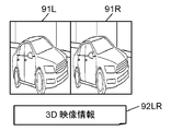
- FIG. 9D is a diagram schematically illustrating an example of a 3D video signal output from the video transmission apparatus and input to the video reception apparatus.
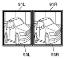
- FIG. 9E is a diagram schematically illustrating an example of a video recognition area set in the 3D video signal by the video recognition area setting unit of the video reception device in the first exemplary embodiment.
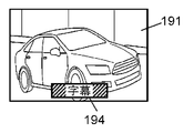
- FIG. 10A is a diagram schematically illustrating an example of a video signal 191 output from the video transmission device and input to the video reception device.
- FIG. 10B is a diagram schematically illustrating an example of a superimposition region set by the video recognition region setting unit of the video reception device in the first exemplary embodiment.
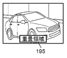
- FIG. 10C is a diagram schematically illustrating an example of a video recognition area set by the video recognition area setting unit of the video reception device in the first exemplary embodiment.
- FIG. 10D is a diagram schematically illustrating an example of a display position of additional information displayed on the display unit of the video reception device in the first exemplary embodiment.
- FIG. 11A is a diagram schematically illustrating an example of a video signal output from the video transmission device and input to the video reception device.
- FIG. 11B is a diagram schematically illustrating an example of a video recognition candidate area set by the video recognition area setting unit of the video reception device in the first exemplary embodiment.
- FIG. 11C is a diagram schematically illustrating an example of a result of content identification processing acquired from the video recognition device by the video reception device in the first exemplary embodiment.
- FIG. 11D is a diagram schematically illustrating an example of a display position of additional information displayed on the display unit of the video reception device in the first exemplary embodiment.
- FIG. 12 is a flowchart schematically showing an operation of content identification processing performed by the video reception device in the first embodiment.
- FIG. 13 is a block diagram schematically illustrating an example of a configuration of a video recognition device and a video reception device according to another embodiment.
- FIG. 1 is a diagram schematically showing an example of a configuration of an additional information display system 10 according to the first embodiment.
- the additional information display system 10 includes a broadcasting station 12, an STB (Set Top Box) 14 that is a video transmission device, a video recognition device 20, an additional information distribution device 30, and a video reception device 40.
- the additional information display system 10 uses the video recognition technology of the video recognition device 20 to identify which content the video received by the video reception device 40 belongs to, and adds additional information related to the content to the additional information.
- the communication system is configured to be able to acquire from the distribution device 30 and display it on the video reception device 40.
- the video receiving device 40, the video recognition device 20, and the additional information distribution device 30 are connected to each other via the communication network 16.
- the communication network 16 is configured by wired, wireless, or a mixture of both.
- the communication network 16 is, for example, the Internet, but may be an intranet, a commercial line, other communication lines, or a mixture thereof.
- the video receiver 40 and the STB 14 are connected to each other via a communication interface.
- the communication interface is, for example, HDMI (registered trademark) (High-Definition Multimedia Interface), but may be a video cable, or may be Wi-Fi (registered trademark), Bluetooth (registered trademark), or wireless LAN (Local Area Network). ) Or the like.
- Broadcast station 12 is a transmission device configured to transmit (broadcast) a broadcast signal.
- the broadcast station 12 converts a television program including a program body and a commercial message (CM) into a video signal and superimposes it on the broadcast signal and broadcasts it.
- the program body and the CM are switched to each other as time passes.
- the program body and CM are referred to as “content”.
- the broadcast station 12 broadcasts content that changes over time.
- the transmission device is not limited to the broadcasting station 12 and may be any device that transmits or broadcasts content that changes over time.
- the broadcast station 12 transmits information including information indicating the characteristic of the content and the video signal of the content (hereinafter referred to as “feature information”) together with the video signal. May be broadcast or transmitted.
- feature information information including information indicating the characteristic of the content and the video signal of the content
- the information including the feature information is referred to as “content related information”.
- Content with unique features includes, for example, content of 3D video (3 Dimensional video images; hereinafter also referred to as “3D video”.
- 3D video signal is also referred to as “3D video signal”) and subtitles. Content including superimposed video, and the like.
- the content-related information related to 3D video includes, for example, characteristic information related to video signal transmission methods (side-by-side method, top-and-bottom method, line-by-line method, frame sequential method, etc.) of 3D video. May be.
- content-related information related to subtitles may include, for example, characteristic information related to the presence / absence of subtitles, the position and size of subtitles, the color of subtitles, fonts, and the like.
- characteristic information regarding the broadcast format of the broadcast signal may be included in the content-related information.
- the STB 14 is a receiver (tuner) configured to receive a broadcast signal broadcast by the broadcast station 12 and extract a video signal.
- the STB 14 may have a function of decoding the received video signal.
- the STB 14 receives a channel selected based on a user's (User) instruction from a plurality of channels broadcasted by the broadcast station 12, and transmits a video interface of the channel to a communication interface (for example, HDMI (registered trademark)).
- a communication interface for example, HDMI (registered trademark)
- the STB 14 can receive the content related information and output it to the video receiving device 40.
- the video transmission apparatus is not limited to the STB 14, and may be a recording apparatus having a recording function, a broadcast signal receiving function, and a video signal output function, for example.
- the STB 14 detects the characteristics, generates content-related information including characteristic information indicating the characteristics, and outputs the content-related information to the video receiving device 40. It may be configured as follows. For example, when 3D video content is broadcast from the broadcast station 12, the video receiving device 40 detects the 3D video signal transmission method, generates characteristic information indicating the detected result (3D video signal transmission method), and the video receiving device 40. It may be configured to output to. Alternatively, when content including video on which subtitles are superimposed is broadcast from the broadcast station 12, the subtitles are detected, and feature information indicating the display position and display size of the detected subtitles is generated to the video reception device 40. It may be configured to output.
- the STB 14 when the STB 14 superimposes a caption or OSD (On Screen Display) on the video signal, the STB 14 is configured to generate feature information regarding the display position and display size of the caption or OSD and output the feature information to the video receiver 40. Also good.
- the feature information that the video transmission device such as the STB 14 detects and generates from the video signal broadcast from the broadcast station 12 and outputs it is also treated as part of the content related information.
- the video receiving device 40 is a video receiving device configured to display video based on a video signal input from the outside on the display unit 54, and is, for example, a television receiver.
- the video receiving device 40 is connected to the communication network 16 and can transmit and receive data to and from the video recognition device 20 and the additional information distribution device 30 via the communication network 16.
- the video receiving device 40 in the present embodiment is configured to be able to:
- the video receiving device 40 performs content specifying processing (content specifying processing based on the video recognition processing) on the video signal input from the video transmitting device (for example, STB 14) via the communication interface, using the video recognition device 20.
- the content specifying process is a process for specifying the content represented by the video signal.
- the video reception device 40 receives the analysis information transmitted from the video recognition device 20 as a result of the content specifying process, and distributes additional information (for example, advertisement information) related to the content based on the analysis information.
- the additional information acquired from the device 30 is superimposed on the video signal and displayed on the display unit 54.
- the video reception device 40 periodically extracts a partial video by periodically cutting out a part from the input video signal, and generates content recognition information and content identification processing (video) generated from the partial video.
- a request for content identification processing based on the recognition processing (hereinafter also referred to as “video recognition request”) is transmitted to the video recognition device 20 via the communication network 16.
- the video reception device 40 acquires the result (analysis information) of the content specifying process for the content recognition information from the video recognition device 20 via the communication network 16.
- additional information related to the acquired content identification processing result (analysis information) is acquired from the additional information distribution device 30 via the communication network 16.
- an image based on the acquired additional information shown as “additional information 51” in FIG. 1) is displayed superimposed on the video being displayed on the display unit. Details of these will be described later.
- the video reception device 40 can receive content-related information output from the STB 14.
- the content related information may include characteristic information indicating the transmission method of the 3D video signal.
- characteristic information indicating the location (coordinates) and size of the area on which the subtitles are superimposed may be included.
- characteristic information indicating the location (coordinates) or size of the area where the caption or OSD is superimposed may be included.
- the content recognition information is information for recognizing a video
- the fingerprint is a hash value of each image constituting a partial video or a moving image.
- the content recognition information may be information (data) that can be used for video recognition processing, and is not limited to a fingerprint (hash value).
- the additional information is “advertising information related to content”
- the additional information is not limited to advertising information.
- tourism information historical information, and person profiles It may be information, URL (Uniform Resource Locator), public gazette information, information about a program being broadcast, social information such as Twitter (registered trademark), and the like.
- URL Uniform Resource Locator
- public gazette information information about a program being broadcast
- social information such as Twitter (registered trademark), and the like.
- the video recognition device 20 is a server device connected to the communication network 16 and is a Web site that performs content specifying processing based on video recognition processing.
- the content specifying process is a process of performing the video recognition process based on the received fingerprint and specifying the content represented by the fingerprint based on the result of the video recognition process.
- the video recognition device 20 performs analysis on the content broadcast by the broadcast station 12 and video recognition processing using the result of the analysis.
- the video recognition device 20 acquires substantially all content broadcast from the broadcast station 12. Then, the acquired content is analyzed, and the time, capacity, broadcast format, content, genre, characters, time table, etc. of the content are examined to generate analysis information. In addition, the video recognition device 20 creates a fingerprint from the video signal of the content acquired from the broadcast station 12.
- the video recognition apparatus 20 may acquire a content by receiving a broadcast signal broadcast from a broadcast station, or receive a video signal transmitted from the broadcast station 12 via a dedicated video line or the like and receive the content. May be obtained. Moreover, this analysis may be performed automatically, for example, and may be performed manually by an operator.
- the analysis information which is the analysis result, is stored in the storage unit 23 of the video recognition device 20 together with information related to the content.
- the video recognition device 20 When the video recognition device 20 receives a video recognition request with a fingerprint transmitted from the video reception device 40 via the communication network 16, the video recognition device 20 generates the fingerprint in advance and stores it in the storage unit 23. The fingerprint corresponding to the stored fingerprint is collated (video recognition process), and the content corresponding to the fingerprint is specified. In this way, the video recognition apparatus 20 performs a content specifying process for determining what content the partial video of the fingerprint transmitted from the video receiving apparatus 40 is created and specifying the content. Then, an analysis result (analysis information) related to the identified content is read from the storage unit 23, and the read information is returned to the video reception device 40 via the communication network 16 as a result of the content identification process.
- analysis result analysis information
- the video recognition processing (content identification processing based on the video recognition processing) by such a method is also referred to as “ACR (Automatic Content Recognition)”.
- the additional information distribution device 30 is a server device connected to the communication network 16 and is a Web site (advertisement distribution site) that holds and distributes advertisement information of various products.
- the additional information distribution device 30 transmits the result of the content specifying process transmitted from the video receiving device 40 (analysis information acquired by the video receiving device 40 from the video recognition device 20 based on the result of the content specifying process) to the communication network 16. Then, additional information related to the result (analysis information) of the content specifying process is transmitted to the video receiver 40 via the communication network 16.
- This additional information is, for example, advertisement information related to the content specified by the content specifying process.
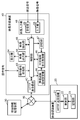
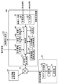
- FIG. 2 is a block diagram schematically showing an example of the configuration of the video recognition device 20 and the video reception device 40 in the first embodiment.
- FIG. 2 shows main circuit blocks related to the operation shown in this embodiment, and other functions and circuit blocks related to the operation are omitted. This is for easy understanding of the operation described in the present embodiment.
- Each circuit block shown in FIG. 2 may be composed of independent circuits, or a program created to realize one or more of the circuit blocks shown in FIG. 2 is executed by a processor. It may be configured to.
- the video recognition device 20 is a server device including an HTTP (Hypertext Transfer Protocol) transmission / reception unit 21, a search unit 22, and a storage unit 23.
- the video recognition device 20 is configured to provide a content identification processing service based on the video recognition processing to the video reception device 40 via the communication network 16.
- the HTTP transmission / reception unit 21 is a communication interface, for example, a communication adapter conforming to the Ethernet (registered trademark) standard.
- the HTTP transmission / reception unit 21 is configured to be able to transmit / receive data to / from the video reception device 40 via the communication network 16.
- the storage unit 23 is a storage device composed of, for example, an HDD (Hard Disk Drive) or the like.
- the storage unit 23 is configured to store a fingerprint of content broadcast from the broadcasting station 12 and analysis information of an analysis result for the content in association with the content. This fingerprint is, for example, a hash value of each image constituting the moving image.
- the storage unit 23 has a slight time delay (for example, 10 seconds) from the broadcast for each content (for example, the program main body or CM).
- the fingerprint and the analysis result (analysis information) are stored in association with each other.
- the analysis result (analysis information) may include, for example, a program title, a CM title, a program outline, a CM outline, a character, a location related to a video, a URL, and the like.
- the search unit 22 When the search unit 22 receives a video recognition request with a fingerprint transmitted from the video receiving device 40 via the HTTP transmission / reception unit 21, the search unit 22 performs a content specifying process based on the video recognition process using the fingerprint, The result (analysis information) is configured to be returned to the video reception device 40 via the HTTP transmission / reception unit 21.
- the search unit 22 receives a video recognition request with a fingerprint transmitted from the video reception device 40 via the communication network 16 and the HTTP transmission / reception unit 21.
- the received fingerprint is collated with the fingerprint stored in the storage unit 23, and a fingerprint corresponding to the received fingerprint is searched (video recognition process).
- the content corresponding to the fingerprint specified by the search result is set as the content corresponding to the received fingerprint (content specifying process).
- the search unit 22 specifies content corresponding to the received fingerprint.
- the search part 22 reads the analysis result (analysis information) matched with the specified content from the memory
- a reply is made to the video receiver 40 via the communication network 16.
- the video receiver 40 includes a control unit 41, an HTTP transmission / reception unit 42, an operation signal reception unit 43, a video output unit 44, a display unit 54, a video extraction unit 45, an additional information display control unit 46, a storage unit 47, and a video recognition area setting.
- the video receiving device 40 performs content identification processing based on video recognition processing using the video recognition device 20, acquires analysis information as a result of the content identification processing from the video recognition device 20, and adds information related to the analysis information.
- Information for example, advertisement information
- an image based on the additional information for example, advertisement information related to the image
- is superimposed on the image (content) based on the received image signal to display the display unit. 54 is displayed.
- the HTTP transmission / reception unit 42 is a communication interface, for example, a communication adapter that conforms to the Ethernet (registered trademark) standard.
- the HTTP transmission / reception unit 42 is configured to be able to transmit / receive data to / from the video recognition device 20 via the communication network 16.
- the operation signal reception unit 43 receives an operation signal (operation signal for the video reception device 40) transmitted by an operation unit (not shown) such as a remote control device (hereinafter abbreviated as “remote control”) that has received a user operation. Is configured to do.
- the operation signal receiving unit 43 may be configured such that a remote controller having a gyro sensor receives a signal that is transmitted based on a physical variation that occurs in the remote controller.
- the video input unit 48 is a receiving circuit and a decoder, and includes a receiving unit 49 configured to receive a broadcast signal transmitted by a broadcasting station, and a video signal and content related information output from a video transmitting device (for example, the STB 14). And an input unit 65 configured to input.
- the video signal received by the video input unit 48 includes content (program body and CM, etc.) that changes over time.
- the receiving unit 49 is configured to receive a broadcast signal transmitted from the broadcast station 12 via an antenna (not shown) or the like.
- the input unit 65 is an interface configured to input a video signal and content related information output from a video transmission device installed outside.
- the input unit 65 is configured to conform to, for example, the HDMI (registered trademark) standard, and can receive a video signal and content related information transmitted from the video transmission device via the HDMI (registered trademark).
- the video transmission device is, for example, the STB 14, but may be a video recording / playback device or the like.
- the input unit may be configured to receive a video signal and content related information transmitted via a video cable, and a video signal and content related information transmitted by wireless communication.
- the video output unit 44 has a function of controlling the display unit 54, controls the display unit 54 based on the video signal input from the video input unit 48, and displays a video based on the video signal on the display unit 54. It is configured as follows. When the additional information is input from the control unit 41, the video output unit 44 superimposes an image based on the additional information on the video being displayed on the display unit 54.
- the display unit 54 is a display configured to display an image based on an image signal, and is, for example, an LCD (Liquid Crystal Display).
- the display unit 54 may be a PDP (Plasma Display Panel), an OLED (Organic Electro Luminescence Display), or the like.
- the additional information display control unit 46 is configured to perform display control of additional information. Specifically, the additional information display control unit 46 generates a fingerprint from the partial video extracted by the video extraction unit 45, and performs content specifying processing based on the generated fingerprint (content specifying processing based on the video recognition processing).
- the image recognition device 20 is used. This fingerprint is, for example, a hash value of each image constituting the partial video.
- the additional information display control unit 46 generates a fingerprint in the effective area (video recognition area or video recognition candidate area) set by the video recognition area setting unit 66. Details of these processes will be described later.
- the additional information display control unit 46 determines where the image (or character string) based on the acquired additional information is to be superimposed on the video being displayed on the display unit 54 in the video recognition region setting unit 66. A determination is made based on the result of the setting process, and an instruction based on the determination is output to the control unit 41.
- the video extraction unit 45 is configured to extract a partial video from the video signal input from the video input unit 48.
- the video extraction unit 45 is configured to extract a partial video that is a part of the video signal for a predetermined time from the video signal at a predetermined cycle. For example, if the predetermined period is 3 seconds and the predetermined time is 3 seconds, the video extraction unit 45 repeats the operation of extracting a partial video of 3 seconds every 3 seconds from the video signal. That is, the operation of continuously extracting the partial video for 3 seconds from the video signal every 3 seconds without a gap is repeated. For example, if the predetermined period is 15 seconds and the predetermined time is 3 seconds, the video extraction unit 45 repeats the operation of extracting a partial video of 3 seconds every 15 seconds from the video signal.
- the partial video extracted from the video signal is not limited to extraction in units of seconds.
- the partial video may be extracted with a predetermined number of frames at the video frame rate.
- the video recognition area setting unit 66 performs a video recognition area setting process on the partial video extracted by the video extraction unit 45.
- superimposition information such as subtitles and OSD (On Screen Display) superimposed on the partial video is detected, and based on the detection result or based on the feature information included in the content related information, Set the effective area.
- the effective area is a video recognition area or a video recognition candidate area. That is, the video recognition area setting unit 66 sets the video recognition area or the video recognition candidate area based on the detection result of the superimposition information or based on the feature information included in the content related information.
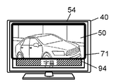
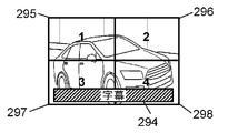
- FIG. 3A is a diagram schematically showing an example of a video displayed on the display unit 54 of the video receiving device 40 in the first exemplary embodiment.
- FIG. 3B is a diagram schematically showing another example of a video displayed on the display unit 54 of the video receiving device 40 in the first exemplary embodiment.
- FIG. 3A shows an example in which the STB 14 outputs the video signal received from the broadcast station 12 to the video receiving device 40 as it is, and the video 50 based on the video signal is displayed on the display unit 54 of the video receiving device 40.
- the STB 14 superimposes the caption 94 on the video signal received from the broadcast station 12 and outputs it to the video receiver 40, and the video based on the video signal (video with the caption 94 superimposed on the video 50).
- the example currently displayed on the display part 54 is shown.
- Some video transmission apparatuses such as the STB 14 have a function of superimposing subtitles, OSD, and the like on the video transmission apparatus side on the video signal transmitted from the broadcasting station 12.
- subtitles, OSDs, and the like that are superposed on video signals by the video transmission device are also referred to as “superimposition information”.
- the STB 14 when the STB 14 superimposes the caption 94 on the video signal transmitted from the broadcasting station 12 and outputs it, the caption 94 is superimposed on the video 50 on the display unit 54 of the video receiver 40 as shown in FIG. 3B. Displayed.
- the video of the same content acquired by the video recognition device 20 from the broadcast station 12 is the video 50 on which the subtitle 94 is not superimposed, as shown in FIG. 3A. .
- the video transmission device such as the STB 14 superimposes the superimposition information such as the caption 94 on the video signal transmitted from the broadcasting station 12
- the video displayed on the display unit 54 of the video reception device 40 and the video recognition are recognized.
- the video acquired by the apparatus 20 from the broadcast station 12 is the same content, the video content differs.
- the video recognition area setting unit 66 performs video recognition area setting processing, detects the display position and display size of the superimposition information, and recognizes the video in the area excluding the superimposition information. An area is set, or a video recognition area is set based on the feature information included in the content related information, and a fingerprint is generated in the video recognition area.
- the video reception device 40 calculates the hash value of each image constituting the partial video in the video recognition area or the video recognition candidate area to obtain a fingerprint.
- caption 94 shown in FIG. 3B is merely an example of superimposition information, and the display position and display size of the superimposition information are limited to the display position and display size of the subtitle 94 shown in FIG. 3B. Is not to be done. The same applies to captions shown in other drawings.
- FIG. 4A is a diagram schematically showing an example of the video recognition area 71 set in the video 50 by the video recognition area setting unit 66 of the video receiving apparatus 40 in the first embodiment.
- FIG. 4B is a diagram schematically illustrating an example of a fingerprint generation area set based on the video recognition area 71 set by the video recognition area setting unit 66 in the video recognition apparatus 20 according to the first exemplary embodiment.
- FIG. 4C is a diagram schematically illustrating an example of the video recognition area 72 set on the entire surface of the video 50 in the video receiving device 40.
- FIG. 4D is a diagram schematically illustrating an example of a fingerprint generation area set on the entire surface of the video 50 in the video recognition device 20.
- the image recognition areas 71 and 72 which are fingerprint generation areas, are indicated by bold lines, but the bold lines are not actually displayed on the display unit 54. .
- FIG. 4A shows an example in which the STB 14 superimposes a caption 94, which is an example of superimposition information, on the video 50, and the video recognition area setting unit 66 sets the video recognition area 71 in an area excluding the caption 94.
- FIG. 4C shows an example in which the video recognition area 72 is set in an area including the subtitle 94 (the entire surface of the video 50) even though the STB 14 superimposes the subtitle 94 on the video 50. At this time, the subtitle 94 is not superimposed on the video 50 acquired from the broadcast station 12 by the video recognition device 20 as shown in FIGS. 4B and 4D.
- FIG. 4C is only shown for comparison with the operation example shown in FIG. 4A, and the video 50 is displayed despite the fact that the video recognition area setting unit 66 has detected superimposition information such as caption 94. It does not indicate that a video recognition area is set on the entire surface of the screen.
- the additional information display control unit 46 performs fingerprinting in the area including the caption 94. Generate.
- the video recognition device 20 generates a fingerprint in the video recognition area 72 of the video 50 as shown in FIG. 4D. There is no caption 94 in this area. For this reason, the fingerprint generated by the video receiving device 40 and the fingerprint generated by the video recognizing device 20 do not match each other, and the content identifying process may fail in the video recognizing device 20.
- the video recognition area setting unit 66 detects a display area (hereinafter referred to as “superimposition area”) of superimposition information such as caption 94.
- the superimposition area of the superimposition information is specified based on the feature information included in the content related information, and the video recognition area 71 is set in an area excluding the superimposition area.
- the additional information display control unit 46 of the video receiver 40 generates a fingerprint in the video recognition area 71 excluding the overlapping area.
- the video recognition device 20 generates a fingerprint in a video recognition area 71 similar to that of the video reception device 40.
- the possibility that the fingerprint generated by the video receiving device 40 and the fingerprint generated by the video recognizing device 20 match each other is relatively high, and the content identifying process is successful in the video recognizing device 20.
- the possibility is relatively high compared to the examples shown in FIGS. 4C and 4D.
- the region where the fingerprint is generated in the video recognition device 20 is set based on the video recognition region set by the video recognition region setting unit 66.
- the video receiving apparatus 40 may be configured to transmit information indicating the video recognition area set by the video recognition area setting unit 66 to the video recognition apparatus 20 together with a fingerprint, for example.
- the storage unit 47 is a storage device configured by, for example, a nonvolatile memory.
- the storage unit 47 displays program meta information such as an electronic program guide (EPG) received by the video input unit 48, additional information acquired from the additional information distribution device 30 via the HTTP transmission / reception unit 42, and display of additional information.
- EPG electronic program guide
- the display control information for the additional information is information for controlling the display of the additional information, and includes information indicating the display period of the additional information, for example.
- the control unit 41 is configured to control each circuit block included in the video reception device 40.
- the control unit 41 is, for example, a nonvolatile memory such as a ROM that stores a program (application program or the like), a CPU that executes the program, and temporarily stores data, parameters, and the like when the CPU executes the program. It consists of a volatile memory such as a RAM for storing.
- control performed by the control unit 41 examples include the following.
- the control unit 41 acquires content related information input together with the video signal.
- the video extraction unit 45 is controlled so that the video extraction unit 45 extracts partial videos from the video signal at a predetermined cycle.
- the video recognition region setting unit 66 sets the video recognition region as a partial video from the feature information included in the content related information, and the additional information display control unit 46 is extracted.
- Each circuit block is controlled to generate (calculate) a fingerprint of the partial video in the video recognition area.
- the fingerprint is transmitted together with the video recognition request to the video recognition device 20 via the HTTP transmission / reception unit 42 and the communication network 16, and content identification processing (content identification processing based on the video recognition processing) is performed on the fingerprint.
- Each circuit block is controlled to request the recognition device 20.
- the result (analysis information) of the content specific process with respect to the fingerprint is acquired from the video recognition apparatus 20 via the communication network 16 and the HTTP transmission / reception part 42, and the additional information based on the result (analysis information) of the content specific process is obtained.
- Each circuit block is controlled so as to be acquired from the additional information distribution device 30 via the communication network 16 and the HTTP transmission / reception unit 42.
- the acquired additional information is stored in the storage unit 47 and output to the video output unit 44, and each circuit block is controlled so that the additional information is superimposed on the video being displayed on the display unit 54 and displayed.
- the additional information display control unit 46 determines that “additional information is not displayed”, the control unit 41 sets each circuit block so that the additional information being displayed on the display unit 54 is not displayed. Control.
- the video reception device 40 When the video reception device 40 requests the video recognition device 20 for content identification processing based on the video recognition processing, the video reception device 40 creates a signal (data) indicating the request for content identification processing, and recognizes the signal as video recognition.
- the additional information display system 10 may be configured to transmit to the video recognition device 20 as a request. For example, such a signal (data) is not transmitted, and the video reception device 40 displays the fingerprint. An agreement may be made in advance between the video reception device 40 and the video recognition device 20 so that the content identification processing based on the video recognition processing is requested to the video recognition device 20 by transmitting to the video recognition device 20.
- the video reception device 40 performs content specifying processing on the video signal using the video recognition device 20. Then, additional information 51 (for example, advertisement information) related to the result of the content specifying process is acquired from the additional information distribution device 30, and the acquired additional information 51 is superimposed on the video signal and displayed on the display unit 54. In addition, the video receiver 40 displays or hides the acquired additional information 51 (for example, advertisement information) according to the display control information of the additional information acquired together with the additional information 51.
- additional information 51 for example, advertisement information
- the video receiving device 40 uses the video recognition area set by the video recognition area setting unit 66 based on the feature information included in the content-related information, or the video recognition area setting unit.
- 66 is a video recognition area or video recognition candidate area set by performing the video recognition area setting process, and is generated from the partial video.
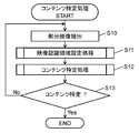
- FIG. 5 is a flowchart schematically showing the operation of the content specifying process performed by the video reception device 40 in the first embodiment.
- the video extraction unit 45 of the video reception device 40 extracts a partial video from the video signal output from the STB 14 and input to the input unit 65 (step S10).
- the video recognition area setting unit 66 performs a video recognition area setting process (step S11).
- the video recognition area setting process is a process in which the video recognition area setting unit 66 sets the video recognition area based on the feature information included in the content-related information or the superimposition information from the partial video extracted by the video extraction unit 45. Is a process for detecting a region (superimposed region) where the image is displayed and setting a video recognition region or a video recognition candidate region in a region excluding the superimposed region. Details of the video recognition area setting process will be described later.
- the additional information display control unit 46 performs the following content specifying process (step S12).
- the additional information display control unit 46 generates a fingerprint based on the partial video extracted by the video extraction unit 45 and the video recognition area or video recognition candidate area set by the video recognition area setting unit 66.
- the generated fingerprint is transmitted to the video recognition apparatus 20 via the HTTP transmission / reception unit 42 according to an instruction from the control unit 41.
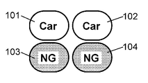
- the video recognition device 20 performs content identification processing based on the video recognition processing using the fingerprint, and sends analysis information (result of content identification processing) related to the identified content to the video reception device 40 via the communication network 16. Send.
- the video recognition device 20 may operate to transmit specific information such as “NG” or “0” as analysis information to the video reception device 40.
- the control unit 41 controls each circuit block so as to receive the analysis information (result of content identification processing) transmitted from the video recognition device 20 and transfer it to the additional information display control unit 46.
- the analysis information is stored in the storage unit 47. Details of these content specifying processes will be described later.
- the additional information display control unit 46 determines from the acquired analysis information whether the content specifying process has succeeded (whether the content has been specified from the fingerprint) (step S13).
- the control unit 41 transmits the analysis information received from the video recognition device 20 to the HTTP transmission / reception based on the instruction from the additional information display control unit 46.
- Each circuit block is controlled to be transmitted to the additional information distribution apparatus 30 via the unit 42 and the communication network 16.
- the additional information distribution device 30 transmits additional information related to the received analysis information to the video reception device 40 through the communication network 16.
- the control unit 41 controls each circuit block so that the additional information transmitted from the additional information distribution device 30 is received via the HTTP transmission / reception unit 42.
- Each circuit is configured to transfer the received additional information to the video output unit 44 and display the additional information superimposed on the video being displayed on the display unit 54 based on an instruction from the additional information display control unit 46. Control the block. Then, a series of processing ends.
- the URL is included in the analysis information acquired from the video recognition device 20, and the control unit 41 designates the URL to access the additional information distribution device 30, and associates the information related to the URL with the analysis information.
- Each device may be configured such that the additional information is acquired from the additional information distribution device 30 as additional information.
- step S13 When it is determined in step S13 that the content specifying process has failed (No), the video reception device 40 repeats the processes of steps S10 to S13 described above for the next partial video.
- step S13 for example, when the video recognition apparatus 20 returns the same analysis result (result of the content specifying process) to a predetermined number of consecutive partial videos (for example, three), the content specifying process is performed.
- the additional information display control unit 46 may be configured to determine that has succeeded.
- the video receiver 40 repeats these series of operations.
- step S11 Next, the video recognition area setting process in step S11 will be described.
- the video receiving device 40 performs the video recognition area setting process in order to increase the accuracy of the content specifying process related to the video signal input from the input unit 65.
- the video receiver 40 examines the characteristics of the video signal.
- the outline of the video recognition area setting process is as follows.
- the video receiving device 40 first displays content-related information including feature information (for example, feature information indicating presence / absence of caption 94, display position and display size of caption 94, transmission method of 3D video signal, etc.) It is detected whether it is input to the video receiver 40 via the input unit 65 together with the signal. If the feature information is input, the video reception device 40 sets a video recognition area using the information, generates a fingerprint in the video recognition area, and performs content specifying processing.
- feature information for example, feature information indicating presence / absence of caption 94, display position and display size of caption 94, transmission method of 3D video signal, etc.
- the video receiver 40 receives the feature of the video signal (for example, The operation of detecting the presence / absence of caption 94, the display position and display size of caption 94, etc. from the video signal itself is performed. Thereafter, content identification processing is performed based on the detection result.
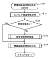
- FIG. 6 is a flowchart schematically showing the operation of the video recognition area setting process performed by the video receiver 40 in the first embodiment.
- the video recognition area setting unit 66 of the video receiving device 40 first acquires content related information related to the video signal input from the STB 14 to the video receiving device 40 via the input unit 65 (step S21).
- the video recognition area setting unit 66 includes, in the content-related information, feature information related to the display area of superimposition information such as subtitles 94 and OSD (information indicating the display position, display size, etc., hereinafter “superimposition area information”. Whether or not) is included (step S22).
- feature information related to the display area of superimposition information such as subtitles 94 and OSD (information indicating the display position, display size, etc., hereinafter “superimposition area information”. Whether or not) is included (step S22).
- step S22 When it is determined in step S22 that the content-related information does not include superimposition area information, the content-related information itself does not exist, or the feature information included in the content-related information is feature information related to 3D video ( In No), the video recognition area setting unit 66 performs the overlapping area specifying process (step S23).
- Superimposition area specifying processing is to detect caption 94, OSD, etc. (superimposition information) from the video signal input to the video receiver 40 via the input unit 65, and display position and display size (superimposition area) of the superimposition information. It is a process to specify. Details of the overlapping area specifying process will be described later.
- the video recognition area setting unit 66 performs the video recognition area specifying process using the information of the overlapping area (superimposition area information) specified in the overlapping area specifying process in step S23 (step S24).
- the video recognition area specifying process is a process for specifying a video recognition area or a video recognition candidate area using the superimposition area information. Details of the image recognition area specifying process will be described later.
- step S22 when the overlapping area information is detected from the content related information (Yes), the image recognition area setting unit 66 performs the image recognition area specifying process using the overlapping area information (step S24).
- step S24 After the video recognition area setting process in step S24 is completed, the process proceeds to step S12 in FIG.
- the video recognition area setting unit 66 can grasp the display position, display size, and the like of the superimposition information such as the caption 94 with relatively high accuracy.
- the overlapping area specifying process in step S23 can be omitted.
- the video recognition area setting unit 66 appropriately sets the video recognition area based on the transmission method of the 3D video signal. be able to. Therefore, content identification processing (content identification processing based on video recognition area identification processing) and acquisition of additional information can be performed faster and with higher accuracy.
- step S23 the superposition area specifying process in step S23 when the superposition area information is not included in the content-related information or when the content-related information is not input to the video reception device 40 will be described.
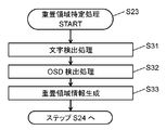
- FIG. 7 is a flowchart schematically showing the operation of the overlapping area specifying process performed by the video reception device 40 in the first embodiment.
- the video recognition area setting unit 66 performs character detection processing on the partial video extracted by the video extraction unit 45 (step S31).
- OCR Optical Character Reader
- the video recognition area setting unit 66 performs OSD detection processing by pattern matching processing (step S32).
- the OSD detection process is a process for detecting the display area (display position and display size) of the OSD.
- the pattern matching processing is performed by, for example, storing the OSD image of STB 14 in advance in the storage unit 47 as a template image, comparing the partial video with the template image, and generating a template image (OSD image) in the partial video. It is a process using a pattern matching method for searching whether or not it is included.
- the image recognition area setting unit 66 detects the detected area (area where the caption 94 is displayed) when the character is detected in the character detection process in step S31, and the OSD is detected in the OSD detection process in step S32. In some cases, the detected area (area where the OSD image is displayed) is set as an overlapping area, and overlapping area information indicating the display position and display size of the overlapping area is generated (step S33). Thereafter, the process proceeds to step S24 in FIG.
- the video reception device 40 may be configured to perform only one of the character detection process in step S31 and the pattern matching process in step S32.
- step S24 the video recognition area specifying process performed in step S24 will be described.
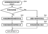
- FIG. 8 is a flowchart schematically showing the operation of the video recognition area specifying process performed by the video receiver 40 in the first embodiment.
- the video recognition area setting unit 66 determines whether or not the overlapping area information is acquired or specified in step S22 or step S23 (step S41).
- step S41 When it is determined in step S41 that the overlapping area information has been acquired or specified (Yes), the video recognition area setting unit 66 includes the overlapping area information included in the content-related information acquired in step S22, Alternatively, a non-superimposition area specifying process is performed based on the superposition area information specified in step S23 (step S44).
- the non-superimposition area specifying process is a process of specifying an area excluding the superimposition area (hereinafter also referred to as “non-superimposition area”) by specifying the superimposition area based on the superimposition area information in the partial video. Details of the non-superimposition region specifying process will be described later.
- the video recognition area setting unit 66 sets the video recognition area in the non-superimposed area specified by the non-superimposed area specifying process in step S44. And the information showing the image
- the information representing the video recognition area generated in step S45 may be transmitted from the video reception device 40 to the video recognition device 20 together with the fingerprint.
- the video recognition area may coincide with the non-superimposed area or may be a part of the non-superimposed area. That is, the video recognition area may be set to all video areas (partial video areas) excluding the overlapping area, or may be set to a part of the video area excluding the overlapping area. It is desirable that the video recognition area is appropriately set according to the accuracy in the content specifying process, the specifications of the video receiving device 40, and the like.
- step S41 When it is determined in step S41 that the superimposed area information has not been acquired or specified (No), the video recognition area setting unit 66 performs a video recognition candidate area setting process (step S42).
- the video recognition candidate area setting process is a process of dividing a partial video into a plurality of areas.
- the partial video divided by the video recognition candidate area setting process is also referred to as “video recognition candidate area”.
- the video recognition candidate area setting process is performed for the following reason.
- step S41 when it is determined that the superimposition area information has not been acquired or specified, the video reception device 40 cannot acquire or specify the superimposition area information because the superimposition information is not superimposed on the video signal. Alternatively, it is difficult to determine whether the superimposition area information cannot be acquired or specified even though the superimposition information is superimposed on the video signal.
- the partial video is divided into a plurality of areas, a fingerprint is generated in each area (each video recognition candidate area), and a content specifying process is performed for each area.
- a content specifying process is performed for each area.
- the partial video is divided into a plurality of regions and the partial video can be divided into a region where the superimposition information is superimposed and a region where the superimposition information is not superimposed, Regarding a region where information is superimposed (video recognition candidate region where superimposition information is superimposed), even if there is a possibility that the content specifying process may fail, a region where superimposition information is not superimposed (video where superimposition information is not superimposed) This is because the possibility of successful content identification processing can be relatively increased with respect to the recognition candidate area. Details of the video recognition candidate area setting process will be described later.
- the video recognition area setting unit 66 generates information representing the video recognition candidate area set in the video recognition candidate area setting process in step S42, and outputs the information to the additional information display control unit 46 (step S43). Thereafter, the process proceeds to step S12 in FIG.
- the information representing the video recognition candidate area generated in step S43 may be transmitted from the video reception device 40 to the video recognition device 20 together with the fingerprint.
- step S44 the non-superimposed area specifying process performed in step S44 will be described with reference to FIGS. 9A to 11C.
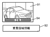
- FIG. 9A is a diagram schematically illustrating an example of the video signal 91 output from the video transmission device and input to the video reception device 40 and the superimposition area information 92.
- FIG. 9B is a diagram schematically illustrating an example of the video recognition area 93 set by the video recognition area setting unit 66 of the video reception device 40 in the first exemplary embodiment.
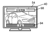
- FIG. 9C is a diagram schematically illustrating an example of a display position of the additional information 98 displayed on the display unit 54 of the video reception device 40 in the first exemplary embodiment.
- the video reception device 40 may acquire content-related information via the communication network 16, for example.
- content-related information including a video signal 91 in which a caption 94 is superimposed on the STB 14 side on a video signal broadcast from the broadcasting station 12, and superimposed area information 92 of the caption 94, Is input from the STB 14 to the video receiver 40.
- the video recognition area setting unit 66 specifies a superimposition area (for example, a display area of the caption 94) based on the acquired superimposition area information 92. Then, an area excluding the superimposition area (for example, an area excluding the caption 94) is specified as a non-superimposition area (non-superimposition area specifying process in step S44).
- the video recognition area setting unit 66 sets the video recognition area 93 in the non-superimposition area (step S45).
- the additional information display control unit 46 generates a fingerprint in the video recognition area 93.
- the additional information display control unit 46 instructs the control unit 41 to transmit information indicating the generated fingerprint and the video recognition area 93 to the video recognition device 20 and performs content specifying processing regarding the video recognition area 93. (Step S12).
- the video recognition area setting unit 66 excludes the caption.
- the fingerprint may be generated by setting the video recognition area in the area, but the video recognition apparatus 20 also acquires the video signal on which the caption is superimposed from the broadcast station 12, so that the area including the caption is included in the area.
- the fingerprint may be generated by setting the image recognition area.
- the video recognition device 20 performs content identification processing by generating a fingerprint based on information indicating the video recognition area 93 acquired from the video reception device 40.
- the video recognition area 93 is indicated by a bold line, but the bold line is not displayed on the display unit 54 of the video receiving device 40.
- the additional information display control unit 46 instructs the control unit 41 to display the additional information 98 acquired from the additional information distribution device 30 on the display unit 54 based on the content specifying process.
- the additional information display control unit 46 determines the display position of the additional information 98 based on the non-superimposed region specified by the video recognition region setting unit 66. That is, the additional information display control unit 46 sets the display position of the additional information 98 in the non-superimposition area so that the additional information 98 does not overlap the superimposition information such as the caption 94. Then, the controller 41 is instructed to display the additional information 98 at the set position.
- the control unit 41 Upon receiving the instruction, the control unit 41 controls the video output unit 44 and the like so that the additional information 98 is displayed at the position instructed by the additional information display control unit 46.
- the additional information display control unit 46 displays additional information 98 on the upper part of the display unit 54 that does not overlap the caption 94.
- step S22 when it is determined that the feature information included in the content-related information is feature information related to 3D video, the video recognition area setting unit 66 recognizes video according to the transmission method of the 3D video signal.
- the area is set to a partial video, and then the process proceeds to step S23 to perform the overlapping area specifying process.
- a video recognition area for generating a fingerprint is set in an area excluding the overlapping area specified in step S23 from the video recognition area set according to the 3D video signal transmission method.
- FIG. 9D is a diagram schematically illustrating an example of 3D video signals 91L and 91R output from the video transmission device and input to the video reception device 40.
- FIG. 9E is a diagram schematically illustrating an example of the video recognition regions 93L and 93R set in the 3D video signal by the video recognition region setting unit 66 of the video reception device 40 in the first embodiment.
- the left-eye video signal 91L is arranged in the left half of one screen
- the right-eye video signal 91R is arranged in the right half of one screen.
- 3D video signals and content-related information including 3D video information 92LR indicating that the video signals are side-by-side 3D video images are input from the STB 14 to the video receiver 40.
- the video recognition area setting unit 66 sets the video recognition area 93L to the left-eye video signal 91L and the right-eye video signal 91R as shown in FIG. 9E.
- a video recognition area 93R is set for each.
- the image recognition areas 93L and 93R are indicated by thick lines for easy understanding, but these thick lines are not displayed on the display unit 54 of the video reception device 40.
- the operation in the video recognition area setting unit 66 differs depending on whether or not the display position and display size of the superimposition information can be detected from the video signal.
- the operation when the display position and display size of the superimposition information can be detected from the video signal will be described.
- FIG. 10A is a diagram schematically illustrating an example of a video signal 191 output from the video transmission device and input to the video reception device 40.
- FIG. 10B is a diagram schematically illustrating an example of the overlapping area 195 set by the video recognition area setting unit 66 of the video reception device 40 according to Embodiment 1.
- FIG. 10C is a diagram schematically illustrating an example of the video recognition area 193 set by the video recognition area setting unit 66 of the video reception device 40 in the first exemplary embodiment.
- FIG. 10D is a diagram schematically illustrating an example of a display position of the additional information 98 displayed on the display unit 54 of the video reception device 40 in the first exemplary embodiment.
- the recognition area setting unit 66 detects the display position and display size of the caption 194 from the video signal 191 and specifies the overlapping area 195 based on the detection result as shown in FIG. 10B (the overlapping area specifying process in step S23). .
- the video recognition area setting unit 66 specifies an area excluding the superimposition area 195 (that is, an area excluding the caption 194) as a non-superimposition area (non-superimposition area specifying process in step S44).
- the video recognition area setting unit 66 sets the video recognition area 193 in the non-superimposed area as shown in FIG. 10C (step S45).
- the additional information display control unit 46 generates a fingerprint in the video recognition area 193.
- the additional information display control unit 46 instructs the control unit 41 to transmit the generated fingerprint and information indicating the video recognition area 193 to the video recognition device 20 and performs content specifying processing regarding the video recognition area 193. (Step S12).
- the video receiving device 40 When it is found from the content-related information that the caption is superimposed on the video signal broadcast by the broadcasting station 12, the video receiving device 40 sets the video recognition area in the area excluding the caption and prints the fingerprint. However, since the video signal on which the caption is superimposed is also acquired by the video recognition device 20, the video reception device 40 may generate a fingerprint in an area including the caption.
- the video recognition device 20 performs content identification processing by generating a fingerprint based on information indicating the video recognition area 193 acquired from the video reception device 40.
- the video recognition area 193 is indicated by a thick line for easy understanding of the description, but the thick line is not displayed on the display unit 54 of the video receiving device 40.
- the overlapping area 195 is shown in FIGS. 10B and 10C, but the overlapping area 195 is not displayed on the display unit 54.
- the additional information display control unit 46 instructs the control unit 41 to display the additional information 98 acquired from the additional information distribution device 30 on the display unit 54 based on the content specifying process.
- the additional information display control unit 46 sets the display position of the additional information 98 in the non-superimposition area specified by the video recognition area setting unit 66 so that the additional information 98 does not overlap the caption 194, and the display position To the control unit 41.
- the control unit 41 receives the instruction, and, for example, as shown in FIG. 10D, the video is displayed so that the additional information 98 is displayed on the upper part of the display unit 54 that does not overlap the caption 194 instructed by the additional information display control unit 46.
- the output unit 44 and the like are controlled.
- the video receiver 40 performs the video recognition candidate area setting process in step S42.
- the video recognition candidate area setting process is as follows.
- FIG. 11A is a diagram schematically illustrating an example of a video signal 291 output from the video transmission device and input to the video reception device 40.
- FIG. 11B is a diagram schematically illustrating an example of the video recognition candidate areas 295 to 298 set by the video recognition area setting unit 66 of the video reception device 40 according to Embodiment 1.
- FIG. 11C is a diagram schematically illustrating an example of the result of the content specifying process acquired by the video reception device 40 in Embodiment 1 from the video recognition device 20.
- FIG. 11D is a diagram schematically illustrating an example of a display position of the additional information 98 displayed on the display unit 54 of the video reception device 40 in the first exemplary embodiment.
- the video recognition area setting unit 66 When the video recognition area setting unit 66 cannot detect the display position and display size of the caption 294 from the video signal 291, the video recognition area setting unit 66 divides the video into a plurality of video recognition candidate areas (video recognition candidates in step S ⁇ b> 42). Area setting process).
- FIG. 11B shows an example in which the video recognition area setting unit 66 divides the partial video into four video recognition candidate areas 295, 296, 297, and 298.
- the video recognition candidate areas 295 to 298 are indicated by bold lines, but the bold lines are not displayed on the display unit 54 of the video receiving device 40.
- the additional information display control unit 46 generates a fingerprint for each of a plurality of video recognition candidate areas (four video recognition candidate areas 295 to 298 in the example shown in FIG. 11B). Then, the additional information display control unit 46 uses the generated plurality of fingerprints and information indicating the video recognition candidate areas (information indicating the four video recognition candidate areas 295 to 298 in the example illustrated in FIG. 11B) to the video recognition apparatus 20. The control unit 41 is instructed to transmit the content to each of the plurality of video recognition candidate areas (four video recognition candidate areas 295 to 298 in the example shown in FIG. 11B) (step S12).
- the two areas of the video recognition candidate areas 297 and 298 include the caption 294, and the two areas of the video recognition candidate areas 295 and 296 do not include the caption 294. Therefore, in two areas of the video recognition candidate areas 295 and 296, the possibility that the content specifying process is successful is higher than that of the video recognition candidate areas 297 and 298.
- the video recognition device 20 performs content identification processing (content identification processing based on the video recognition processing) using the fingerprints generated in the video recognition candidate areas 295 to 298.
- content identification processing content identification processing based on the video recognition processing
- the recognition candidate areas 295 and 296 the content specifying process is successful, and as a result of the content specifying process, the analysis information 101 and 102 of “Car” is returned to the video receiving apparatus 40.
- An example is shown in which the identification process has failed and analysis information 103 and 104 of “NG” is returned to the video reception device 40 as a result of the content identification process.
- the video recognition device 20 performs fingerprinting in each region based on information indicating the video recognition candidate regions acquired from the video receiving device 40 (information indicating the four video recognition candidate regions 295 to 298 in the example shown in FIG. 11B). , And the content specifying process for each of these areas is performed.
- the additional information display control unit 46 acquires additional information from the additional information distribution device 30 based on the result of the content specifying process in the video recognition candidate area (for example, the video recognition candidate areas 295 and 296) for which the content specifying process has been successful. Then, the controller 41 is instructed. Then, the control unit 41 is instructed to display the acquired additional information 98 on the display unit 54.
- the additional information display control unit 46 determines that the superimposition information is displayed in the video recognition candidate area where the content specifying process has failed and the superimposition information is not displayed in the video recognition candidate area where the content specifying process has been successful. can do. Therefore, in order to prevent the additional information 98 from overlapping the superimposition information (for example, caption 194), the additional information display control unit 46 sets the display position of the additional information 98 in the video recognition candidate area where the content specifying process has been successful. Then, the controller 41 is instructed for the position. In response to the instruction, the control unit 41 controls the video output unit 44 and the like so that the additional information 98 is displayed at the instructed position in the video recognition candidate area where the content specifying process is successful.
- the additional information display control unit 46 performs the content identification process.
- the control unit 41 is instructed to display the additional information 98 in the video recognition candidate areas 295 and 296 that have succeeded. Receiving this instruction, the control unit 41 controls the video output unit 44 and the like so that the additional information 98 is displayed in the video recognition candidate areas 295 and 296. Accordingly, the additional information 98 is displayed on the upper portion of the display unit 54 that does not overlap the caption 294, as shown in FIG. 11D, for example.
- 9C, 10D, and 11D show examples in which the additional information is displayed on the upper portion of the display unit 54. However, this is merely an example of the display position of the additional information.
- the display position and display size of information are not limited to the display position and display size of additional information shown in FIGS. 9C, 10D, and 11D.
- step S12 Next, the content specifying process based on the video recognition process performed in step S12 will be described.
- FIG. 12 is a flowchart schematically showing the operation of the content specifying process performed by the video receiving device 40 in the first embodiment.
- the additional information display control unit 46 of the video reception device 40 acquires information indicating the partial video extracted by the video extraction unit 45 and the video recognition region or video recognition candidate region set by the video recognition region setting unit 66 (step S51). ).
- the additional information display control unit 46 determines whether the image recognition area setting unit 66 sets the image recognition area or the image recognition candidate area (step S52).
- step S52 when it is determined that the image recognition area setting unit 66 sets the image recognition candidate area (Yes), the additional information display control unit 46 calculates a fingerprint in each image recognition candidate area. (Step S53). The additional information display control unit 46 repeats step S53 until fingerprints are calculated for all video recognition candidate regions (step S54).
- the additional information display control unit 46 instructs the control unit 41 to transmit all the fingerprints calculated in step S53 to the video recognition device 20. Upon receiving the instruction, the control unit 41 transmits all the fingerprints calculated in step S53 together with the video recognition request to the video recognition device 20 via the HTTP transmission / reception unit 42 and the communication network 16. Is controlled (step S55).
- the additional information display control unit 46 may instruct the control unit 41 to transmit information indicating the video recognition candidate area to the video recognition device 20 together with the fingerprint.
- the video recognition device 20 that has received the fingerprint performs content identification processing (content identification processing based on the video recognition processing) for each of the video recognition candidate areas using the fingerprints. Then, the video recognition device 20 returns analysis information of the result of the content specifying process to the video reception device 40.
- content identification processing content identification processing based on the video recognition processing
- the video recognition apparatus 20 generates a plurality of fingerprints based on the information indicating the video recognition candidate areas acquired from the video reception apparatus 40, and uses the fingerprints to specify the content specifying process for each of the video recognition candidate areas. Shall be performed.
- step S52 when it is determined that the video recognition area set by the video recognition area setting unit 66 is a video recognition area (No), the additional information display control unit 46 calculates a fingerprint in the video recognition area ( Step S58).
- the additional information display control unit 46 instructs the control unit 41 to transmit the fingerprint calculated in step S58 to the video recognition device 20.
- the control unit 41 controls each circuit block so that the fingerprint calculated in step S58 is transmitted to the video recognition device 20 via the HTTP transmission / reception unit 42 and the communication network 16 together with the video recognition request. (Step S55).
- the additional information display control unit 46 may instruct the control unit 41 to transmit information indicating the video recognition area to the video recognition device 20 together with the fingerprint.
- the video recognition device 20 that has received the fingerprint performs content identification processing (content identification processing based on the video recognition processing) using the fingerprint. Then, the video recognition device 20 returns analysis information of the result of the content specifying process to the video reception device 40.
- the video recognition device 20 generates a fingerprint based on the information indicating the video recognition area acquired from the video reception device 40 and performs content specifying processing.
- the control unit 41 of the video reception device 40 receives the analysis information (result of content identification processing) transmitted from the video recognition device 20 through the communication network 16 as a result of step S55 via the HTTP transmission / reception unit 42. Each circuit block is controlled, and the received analysis information is transferred to the additional information display control unit 46 (step S56).
- the additional information display control unit 46 instructs the control unit 41 to store the analysis information in the storage unit 47.
- the control unit 41 controls each circuit block so as to store the analysis information in the storage unit 47 (step S57). Thereafter, the process proceeds to step S13 in FIG.
- the video reception device 40 is configured to transmit and receive data via the communication network 16, and includes the input unit 65, the video extraction unit 45, and the video recognition area setting unit 66. , A control unit 41, and an additional information display control unit 46.
- the input unit 65 is configured to input a video signal output from an external video transmission device (for example, STB 14) and content-related information including feature information.
- the video extraction unit 45 is configured to extract a partial video for video recognition processing from the video signal.
- the video recognition area setting unit 66 is configured to set the video recognition area for the partial video based on the feature information included in the content related information.
- the control unit 41 sends a fingerprint to the video recognition device 20 connected to the communication network 16 to request video recognition processing, obtains the result of the video recognition processing from the video recognition device 20, and performs the video recognition processing. Control is performed to acquire additional information (for example, advertisement information) based on the result from the additional information distribution device 30 connected to the communication network 16.
- the additional information display control unit 46 is configured to generate a fingerprint in the video recognition area of the partial video.
- a video transmission apparatus such as STB 14 may superimpose superimposition information such as subtitles or OSD on a video signal transmitted from the broadcast station 12 and output it.
- superimposition information such as subtitles or OSD
- such superimposition information is not included in the content video acquired by the video recognition device 20 from the broadcast station 12. Therefore, when a fingerprint is generated from the video signal including the superimposition information and the video recognition process using the fingerprint is requested to the video recognition apparatus 20, the video recognition apparatus 20 uses the fingerprint to perform a video recognition process ( The content identification process based on the video recognition process may fail.
- the video recognition area setting unit 66 sets the video recognition area for the partial video based on the feature information included in the content related information
- the additional information display control unit 46 sets the partial information.
- the fingerprint is generated in the video recognition area of the video.
- the video receiving device 40 can generate a fingerprint in the video recognition region set in the region excluding superimposition information such as subtitles and OSD for the video signal input from the video transmitting device.
- Video recognition processing (content identification processing based on video recognition processing) using the apparatus 20 can be performed with high accuracy.
- the broadcast station 12 may broadcast 3D video content.
- the video recognition area setting unit 66 sets the video recognition area based on the information as a part. Can be set to video. Therefore, the video receiving device 40 also uses the video recognition device 20 to generate a fingerprint corresponding to the 3D video and perform high-accuracy video recognition processing (content identification processing based on the video recognition processing) for 3D video content. Can be done.
- the video receiving device 40 can acquire additional information based on the result of the video recognition processing from the additional information distribution device 30 and superimpose it on the video signal.
- the video receiving device 40 may include a display unit 54 configured to display a video in which the additional information 51 is superimposed on the video signal.
- the video recognition area setting unit 66 may be configured to set the video recognition area in an area excluding the area where the superimposition information is superimposed when the content related information includes feature information related to the superimposition information. Good.
- the video recognition area setting unit 66 can set the video recognition area in an area not including superimposition information such as subtitles and OSD. That is, the additional information display control unit 46 can generate a fingerprint in a video recognition area set in an area excluding superimposition information such as subtitles and OSD, so that the video reception apparatus 40 uses the video recognition apparatus 20. Thus, it is possible to accurately perform the video recognition process (content specifying process based on the video recognition process).
- the additional information display control unit 46 may be configured to perform control for superimposing the additional information on the video recognition area of the video signal.
- the video receiver 40 can display the additional information at a position that does not overlap the superimposition information. Therefore, in the video reception device 40, even if superimposition information such as captions and OSD is superimposed on the video signal input from the video transmission device, the superimposition information is hidden in the additional information and visibility is impaired. Can be prevented.
- the first embodiment has been described as an example of the technique disclosed in the present application.
- the technology in the present disclosure is not limited to this, and can also be applied to embodiments in which changes, replacements, additions, omissions, and the like are performed.
- the configuration in which the video reception device 40 includes the display unit 54 has been described.
- the video reception device in the present embodiment is not limited to this configuration.
- the video receiving apparatus may not include the display unit.
- FIG. 13 is a block diagram schematically illustrating an example of the configuration of the video reception device 140 according to another embodiment.
- the video receiving apparatus 140 shown in FIG. 13 is different from the video receiving apparatus 40 shown in FIG. 2 in the first embodiment mainly in the following points.
- the video reception device 140 does not include the display unit 54, and the video output unit 144 is configured to output a video signal to the video display device 154 installed outside in a wired or wireless manner.
- a video reception device 140 for example, a video recording function, a broadcast signal reception function, a video signal input function, and a video signal output function are provided, and a video signal is transmitted to a video display device 154 installed outside.
- a recording apparatus configured as described above. Examples of such a recording apparatus include a hard disk recorder, a DVD recorder, and a BD recorder.
- FIG. 13 shows main circuit blocks related to the operation described in this embodiment, and functions and circuit blocks (for example, a recording function) related to other operations are omitted.
- the additional information display control unit 46 determines whether or not the additional information 51 is superimposed on the video signal output from the video output unit 144 to the video display device 154.
- the operation in the additional information display control unit 46 is substantially the same as that in the first embodiment. Also in the video receiving apparatus 140 having such a configuration, the same effect as that of the video receiving apparatus 40 shown in the first embodiment can be obtained.
- the video recognition region setting unit 66 is a signal that requests output of content-related information including feature information when the feature information is not included in the content-related information or when the content-related information is not output from the video transmission device. May be configured to instruct the control unit 41 to output to the video transmission device. Thereby, when the feature information regarding superimposition information such as subtitles and OSD is not output from the video transmission device, the video reception devices 40 and 140 request the video transmission device to output the content related information including the feature information. Is possible.
- each component shown in this embodiment may be configured by an independent dedicated circuit, or a program created so as to realize one or more of these operations is executed by a processor. It may be configured to execute.
- the program at this time may be acquired by downloading from a server or the like, or may be acquired via a predetermined recording medium (for example, an optical disk such as a CD-ROM, a magnetic disk, a semiconductor memory, or the like).
- each operation in the server shown in this embodiment may be centrally processed by a single server or may be distributedly processed by a plurality of servers.
- the present disclosure can be applied to a video reception device that can acquire additional information related to a video signal input from a video transmission device installed outside and superimpose the acquired additional information on the video signal.
- the present disclosure is applicable to a television receiver, a hard disk recorder, a DVD recorder, a BD recorder, and the like.
- Additional information display system 12 Broadcasting station 14 STB Reference Signs List 16 Communication network 20 Video recognition device 21, 42 HTTP transmission / reception unit 22 Search unit 23, 47 Storage unit 30 Additional information distribution device 40, 140 Video reception device 41 Control unit 43 Operation signal reception unit 44, 144 Video output unit 45 Video extraction unit 46 Additional Information Display Control Unit 48 Video Input Unit 49 Receiving Unit 50 Video 51, 98 Additional Information 54 Display Unit 65 Input Unit 66 Video Recognition Area Setting Unit 71, 72, 93, 93R, 93L, 193 Video Recognition Area 91, 91R, 91L, 191, 291 Video signal 92 Superimposition area information 92LR 3D video information 94, 194, 294 Subtitle 101, 102, 103, 104 Analysis information 154 Video display device 195 Superposition area 295, 296, 297, 298 Video recognition candidate area
Abstract
Description
以下、図1~図12を用いて、実施の形態1を説明する。
[1-1-1.システム構成の概略]
図1は、実施の形態1における付加情報表示システム10の構成の一例を概略的に示す図である。付加情報表示システム10は、放送局12、映像送信装置であるSTB(Set Top Box)14、映像認識装置20、付加情報配信装置30、および映像受信装置40を備える。付加情報表示システム10は、映像認識装置20が有する映像認識技術を利用して、映像受信装置40が受信した映像がどのコンテンツのものかを特定し、そのコンテンツに関連する付加情報を、付加情報配信装置30から取得して映像受信装置40に表示する、ことができるように構成された通信システムである。
図2は、実施の形態1における映像認識装置20および映像受信装置40の構成の一例を概略的に示すブロック図である。
以上のように構成された付加情報表示システム10の動作を、図5~図13を用いて説明する。
図5は、実施の形態1における映像受信装置40で行うコンテンツ特定処理の動作を概略的に示すフローチャートである。
本実施の形態において、映像受信装置40が映像認識領域設定処理を行うのは、入力部65から入力される映像信号に関するコンテンツ特定処理の精度を高めるためである。そのために、映像受信装置40は、その映像信号の特徴を調べる。
図7は、実施の形態1における映像受信装置40で行う重畳領域特定処理の動作を概略的に示すフローチャートである。
図8は、実施の形態1における映像受信装置40で行う映像認識領域特定処理の動作を概略的に示すフローチャートである。
ここでは、重畳領域情報が含まれたコンテンツ関連情報が映像信号とともに映像受信装置40に入力されているときの映像受信装置40の動作と、コンテンツ関連情報に重畳領域情報が含まれていない(またはコンテンツ関連情報そのものがない)ために映像信号から重畳領域情報を検出するときの映像受信装置40の動作の、それぞれについて説明する。
図11Aは、映像送信装置から出力され映像受信装置40に入力される映像信号291の一例を概略的に示す図である。図11Bは、実施の形態1における映像受信装置40の映像認識領域設定部66が設定した映像認識候補領域295~298の一例を概略的に示す図である。図11Cは、実施の形態1における映像受信装置40が映像認識装置20から取得したコンテンツ特定処理の結果の一例を概略的に示す図である。図11Dは、実施の形態1における映像受信装置40の表示部54に表示された付加情報98の表示位置の一例を概略的に示す図である。
図12は、実施の形態1における映像受信装置40で行うコンテンツ特定処理の動作を概略的に示すフローチャートである。
以上のように、本実施の形態において、映像受信装置40は、通信ネットワーク16を介してデータの送受信を行えるように構成されており、入力部65、映像抽出部45、映像認識領域設定部66、制御部41、および付加情報表示制御部46、を備える。入力部65は、外部に設置された映像送信装置(例えば、STB14)から出力される映像信号と特徴情報を含むコンテンツ関連情報とを入力するように構成されている。映像抽出部45は、その映像信号から映像認識処理用の部分映像を抽出するように構成されている。映像認識領域設定部66は、コンテンツ関連情報に含まれた特徴情報に基づき部分映像に映像認識領域を設定するように構成されている。制御部41は、通信ネットワーク16に接続された映像認識装置20にフィンガープリントを送信して映像認識処理を依頼し、その映像認識処理の結果を映像認識装置20から取得し、その映像認識処理の結果に基づく付加情報(例えば、広告情報)を通信ネットワーク16に接続された付加情報配信装置30から取得する制御を行うように構成されている。付加情報表示制御部46は、部分映像の映像認識領域でフィンガープリントを生成するように構成されている。
以上のように、本出願において開示する技術の例示として、実施の形態1を説明した。しかしながら、本開示における技術は、これに限定されず、変更、置き換え、付加、省略等を行った実施の形態にも適用できる。また、上記実施の形態1で説明した各構成要素を組み合わせて、新たな実施の形態とすることも可能である。
12 放送局
14 STB
16 通信ネットワーク
20 映像認識装置
21,42 HTTP送受信部
22 検索部
23,47 記憶部
30 付加情報配信装置
40,140 映像受信装置
41 制御部
43 操作信号受信部
44,144 映像出力部
45 映像抽出部
46 付加情報表示制御部
48 映像入力部
49 受信部
50 映像
51,98 付加情報
54 表示部
65 入力部
66 映像認識領域設定部
71,72,93,93R,93L,193 映像認識領域
91,91R,91L,191,291 映像信号
92 重畳領域情報
92LR 3D映像情報
94,194,294 字幕
101,102,103,104 解析情報
154 映像表示装置
195 重畳領域
295,296,297,298 映像認識候補領域
Claims (11)
- 通信ネットワークを介してデータの送受信を行えるように構成された映像受信装置であって、
映像信号と前記映像信号の特徴を示す特徴情報を含むコンテンツ関連情報とを入力するように構成された入力部と、
前記映像信号から映像認識処理用の部分映像を抽出するように構成された映像抽出部と、
前記特徴情報に基づき前記部分映像に映像認識領域を設定するように構成された映像認識領域設定部と、
前記通信ネットワークに接続された映像認識装置にコンテンツ認識情報を送信して映像認識処理を依頼し、前記映像認識処理の結果を前記映像認識装置から取得し、前記通信ネットワークに接続された付加情報配信装置から前記映像認識処理の結果に基づく付加情報を取得する制御を行うように構成された制御部と、
前記部分映像の前記映像認識領域で前記コンテンツ認識情報を生成するように構成された付加情報表示制御部と、を備えた、
映像受信装置。 - 前記映像信号に前記付加情報を重畳した映像を表示するように構成された表示部、をさらに備えた、
請求項1に記載の映像受信装置。 - 前記付加情報表示制御部は、前記映像信号の前記映像認識領域に前記付加情報を重畳する制御を行うように構成された、
請求項1に記載の映像受信装置。 - 前記映像認識領域設定部は、前記コンテンツ関連情報が入力されないときに、前記コンテンツ関連情報を要求する信号を出力するように前記制御部に指示を出すように構成された、
請求項1に記載の映像受信装置。 - 前記映像認識領域設定部は、前記コンテンツ関連情報に重畳情報に関する特徴情報が含まれているとき、前記重畳情報が重畳された領域を除く領域に前記映像認識領域を設定するように構成された、
請求項1に記載の映像受信装置。 - 通信ネットワークを介してデータの送受信を行えるように構成された映像受信装置における映像認識方法であって、
外部から入力される映像信号から映像認識処理用の部分映像を抽出するステップと、
外部から入力される、前記映像信号の特徴を示す特徴情報を含んだコンテンツ関連情報を受け取るステップと、
前記特徴情報に基づき前記部分映像に映像認識領域を設定するステップと、
前記部分映像の前記映像認識領域でコンテンツ認識情報を生成するステップと、
前記通信ネットワークに接続された映像認識装置に、前記コンテンツ認識情報を送信して映像認識処理を依頼し、前記映像認識処理の結果を前記映像認識装置から取得するステップと、
前記映像認識処理の結果に基づく付加情報を、前記通信ネットワークに接続された付加情報配信装置から取得するステップと、
を備えた映像認識方法。 - 前記映像信号に前記付加情報を重畳した映像を表示部に表示するステップをさらに備えた、
請求項6に記載の映像認識方法。 - 前記映像信号の前記映像認識領域に前記付加情報を重畳するステップをさらに備えた、
請求項6に記載の映像認識方法。 - 前記コンテンツ関連情報が入力されないときに、前記コンテンツ関連情報を要求する信号を出力するステップをさらに備えた、
請求項6に記載の映像認識方法。 - 前記コンテンツ関連情報に字幕に関する特徴情報が含まれているとき、前記字幕が重畳された領域を除く領域に前記映像認識領域を設定する、
請求項6に記載の映像認識方法。 - 通信ネットワークを介して互いにデータの送受信を行えるように構成された、映像受信装置、映像認識装置、および付加情報配信装置、を備えた付加情報表示システムであって、
前記映像受信装置は、
映像信号と前記映像信号の特徴を示す特徴情報を含むコンテンツ関連情報とを入力するように構成された入力部と、
前記映像信号から映像認識処理用の部分映像を抽出するように構成された映像抽出部と、
前記特徴情報に基づき前記部分映像に映像認識領域を設定するように構成された映像認識領域設定部と、
前記映像認識装置に前記通信ネットワークを介してコンテンツ認識情報を送信して映像認識処理を依頼し、前記映像認識処理の結果を前記映像認識装置から前記通信ネットワークを介して取得し、前記付加情報配信装置から前記映像認識処理の結果に基づく付加情報を前記通信ネットワークを介して取得する制御を行うように構成された制御部と、
前記部分映像の前記映像認識領域で前記コンテンツ認識情報を生成するように構成された付加情報表示制御部と、を備え
前記映像認識装置は、
前記通信ネットワークを介して受信した前記コンテンツ認識情報に関する映像認識処理を行い、前記映像認識処理の結果を前記通信ネットワークを介して前記映像受信装置に送信するように構成され、
前記付加情報配信装置は、
前記通信ネットワークを介して受信した前記映像認識処理の結果に対応する付加情報を前記通信ネットワークを介して前記映像受信装置に送信するように構成された、
付加情報表示システム。
Priority Applications (3)
| Application Number | Priority Date | Filing Date | Title |
|---|---|---|---|
| JP2015511847A JP6240899B2 (ja) | 2013-09-04 | 2014-07-03 | 映像受信装置、映像認識方法および付加情報表示システム |
| US14/888,444 US9900650B2 (en) | 2013-09-04 | 2014-07-03 | Video reception device, video recognition method, and additional information display system |
| EP14838765.7A EP3043571A4 (en) | 2013-09-04 | 2014-07-03 | VIDEO RECEIVING DEVICE, VIDEO RECOGNITION METHOD, AND ADDITIONAL INFORMATION DISPLAY SYSTEM |
Applications Claiming Priority (4)
| Application Number | Priority Date | Filing Date | Title |
|---|---|---|---|
| JP2013-182715 | 2013-09-04 | ||
| JP2013182715 | 2013-09-04 | ||
| JP2014063496 | 2014-03-26 | ||
| JP2014-063496 | 2014-03-26 |
Publications (1)
| Publication Number | Publication Date |
|---|---|
| WO2015033501A1 true WO2015033501A1 (ja) | 2015-03-12 |
Family
ID=52628005
Family Applications (1)
| Application Number | Title | Priority Date | Filing Date |
|---|---|---|---|
| PCT/JP2014/003548 WO2015033501A1 (ja) | 2013-09-04 | 2014-07-03 | 映像受信装置、映像認識方法および付加情報表示システム |
Country Status (4)
| Country | Link |
|---|---|
| US (1) | US9900650B2 (ja) |
| EP (1) | EP3043571A4 (ja) |
| JP (1) | JP6240899B2 (ja) |
| WO (1) | WO2015033501A1 (ja) |
Cited By (2)
| Publication number | Priority date | Publication date | Assignee | Title |
|---|---|---|---|---|
| WO2017135120A1 (en) * | 2016-02-03 | 2017-08-10 | Sharp Kabushiki Kaisha | Computationally efficient frame rate conversion system |
| JP2018523419A (ja) * | 2015-04-23 | 2018-08-16 | ソレンソン メディア インコーポレイテッド | 自動コンテンツ認識フィンガープリントシーケンス照合 |
Families Citing this family (3)
| Publication number | Priority date | Publication date | Assignee | Title |
|---|---|---|---|---|
| CN107690078B (zh) * | 2017-09-28 | 2020-04-21 | 腾讯科技(深圳)有限公司 | 弹幕信息显示方法、提供方法以及设备 |
| CN108174270B (zh) * | 2017-12-28 | 2020-12-01 | Oppo广东移动通信有限公司 | 数据处理方法、装置、存储介质及电子设备 |
| CN115706819A (zh) * | 2021-08-17 | 2023-02-17 | 鸿富锦精密工业(深圳)有限公司 | 网页视频播放方法、装置、电子设备及存储介质 |
Citations (4)
| Publication number | Priority date | Publication date | Assignee | Title |
|---|---|---|---|---|
| JPH10214258A (ja) | 1997-01-28 | 1998-08-11 | Victor Co Of Japan Ltd | データ処理システム |
| JP2002209204A (ja) * | 2000-04-14 | 2002-07-26 | Nippon Telegr & Teleph Corp <Ntt> | 放送情報に関連した情報の取得方法及びシステム並びに装置 |
| JP2004007323A (ja) * | 2001-06-11 | 2004-01-08 | Matsushita Electric Ind Co Ltd | テレビジョン放送受信機 |
| JP2010164901A (ja) * | 2009-01-19 | 2010-07-29 | Sharp Corp | Osd信号処理装置、av装置、映像表示システム、及びosd表示方法 |
Family Cites Families (100)
| Publication number | Priority date | Publication date | Assignee | Title |
|---|---|---|---|---|
| JPH04245552A (ja) | 1991-01-31 | 1992-09-02 | Canon Inc | データベース検索方法 |
| JPH09185720A (ja) | 1995-12-28 | 1997-07-15 | Canon Inc | 画像抽出装置 |
| JP3731952B2 (ja) | 1996-10-18 | 2006-01-05 | シャープ株式会社 | 動画像検索用情報生成装置 |
| JP2000287189A (ja) | 1999-03-31 | 2000-10-13 | Toshiba Corp | テレビ番組の視聴管理装置 |
| JP3485020B2 (ja) | 1999-04-09 | 2004-01-13 | 日本電気株式会社 | 文字認識方法及び装置ならびに記憶媒体 |
| US8205223B2 (en) | 2000-04-12 | 2012-06-19 | Lg Electronics Inc. | Method and video device for accessing information |
| KR100566794B1 (ko) | 2000-04-14 | 2006-04-03 | 니뽄 덴신 덴와 가부시키가이샤 | 방송 정보에 관련된 정보의 취득 방법, 시스템 및 장치 |
| CN100592788C (zh) | 2000-04-14 | 2010-02-24 | 日本电信电话株式会社 | 与广播信息相关的信息取得方法、系统和装置 |
| JP2002016885A (ja) | 2000-06-30 | 2002-01-18 | Pioneer Electronic Corp | 映像再生装置及び映像再生方法 |
| US20020126990A1 (en) | 2000-10-24 | 2002-09-12 | Gary Rasmussen | Creating on content enhancements |
| JP2002175311A (ja) | 2000-12-08 | 2002-06-21 | Nippon Telegr & Teleph Corp <Ntt> | 映像情報登録方法、映像情報登録装置、映像情報検索方法及び映像情報検索装置 |
| US6829015B2 (en) | 2001-01-19 | 2004-12-07 | Samsung Electronics Co., Ltd. | Device and method for realizing transparency in an on screen display |
| JP2002232372A (ja) | 2001-01-31 | 2002-08-16 | Matsushita Electric Ind Co Ltd | 放送番組関連情報提供装置 |
| KR20020072453A (ko) | 2001-03-10 | 2002-09-16 | 삼성전자 주식회사 | 재생장치 및 부가정보 서비스 서버 시스템 |
| JP2002334010A (ja) | 2001-05-11 | 2002-11-22 | Tsubasa System Co Ltd | 広域ネットワークシステム |
| US20030084462A1 (en) * | 2001-10-26 | 2003-05-01 | Junichi Kubota | Digital boradcast reception device and method thereof, and printing device and method thereof |
| US20030149983A1 (en) * | 2002-02-06 | 2003-08-07 | Markel Steven O. | Tracking moving objects on video with interactive access points |
| JP2004104368A (ja) | 2002-09-06 | 2004-04-02 | Sony Corp | 画像データ処理方法、画像データ処理プログラム及び立体画像表示装置 |
| KR100930351B1 (ko) * | 2003-02-25 | 2009-12-08 | 엘지전자 주식회사 | 고밀도 광디스크의 그래픽 및 서브타이틀 데이터관리방법 |
| US20040237102A1 (en) | 2003-03-07 | 2004-11-25 | Richard Konig | Advertisement substitution |
| US7738704B2 (en) * | 2003-03-07 | 2010-06-15 | Technology, Patents And Licensing, Inc. | Detecting known video entities utilizing fingerprints |
| US7809154B2 (en) | 2003-03-07 | 2010-10-05 | Technology, Patents & Licensing, Inc. | Video entity recognition in compressed digital video streams |
| JP4374902B2 (ja) | 2003-05-16 | 2009-12-02 | 富士通株式会社 | 類似画像検索装置、類似画像検索方法、および類似画像検索プログラム |
| JP4109185B2 (ja) | 2003-12-01 | 2008-07-02 | 日本電信電話株式会社 | 映像シーン区間情報抽出方法,映像シーン区間情報抽出装置,映像シーン区間情報抽出プログラムおよびそのプログラムを記録した記録媒体 |
| JP2005167894A (ja) | 2003-12-05 | 2005-06-23 | Matsushita Electric Ind Co Ltd | コンテンツ切替方法、およびチャンネル切替方法 |
| JP2005347806A (ja) | 2004-05-31 | 2005-12-15 | Toshiba Corp | 電子機器および該電子機器にて実行される番組情報取得方法 |
| JP2006030244A (ja) | 2004-07-12 | 2006-02-02 | Matsushita Electric Ind Co Ltd | 情報端末及びプログラム |
| WO2006030742A1 (ja) | 2004-09-14 | 2006-03-23 | Matsushita Electric Industrial Co., Ltd. | 機器制御システムおよび機器制御方法 |
| US20060200842A1 (en) | 2005-03-01 | 2006-09-07 | Microsoft Corporation | Picture-in-picture (PIP) alerts |
| JP2006303936A (ja) | 2005-04-21 | 2006-11-02 | Matsushita Electric Ind Co Ltd | コンテンツデータ、受信装置、生成装置および送信装置 |
| JP4707713B2 (ja) | 2005-08-11 | 2011-06-22 | 三菱電機株式会社 | 映像記録装置及びシーンチェンジ抽出方法 |
| JP3894940B2 (ja) | 2005-08-11 | 2007-03-22 | 三菱電機株式会社 | 映像音声記録装置 |
| JP4757876B2 (ja) | 2005-09-30 | 2011-08-24 | パイオニア株式会社 | ダイジェスト作成装置およびそのプログラム |
| JP2007134948A (ja) | 2005-11-10 | 2007-05-31 | Matsushita Electric Ind Co Ltd | 駐車車両搭乗者撮像装置 |
| US20070157242A1 (en) | 2005-12-29 | 2007-07-05 | United Video Properties, Inc. | Systems and methods for managing content |
| JP4871668B2 (ja) | 2006-08-01 | 2012-02-08 | キヤノン株式会社 | 画像処理システム、画像処理方法及びプログラム |
| JP2008040622A (ja) | 2006-08-02 | 2008-02-21 | Sharp Corp | 広告提供システム、広告提供装置、広告表示装置、広告提供方法およびプログラム |
| JP2008116792A (ja) | 2006-11-07 | 2008-05-22 | Sharp Corp | 表示制御装置、映像表示機器及び表示制御方法 |
| JP4746568B2 (ja) | 2007-01-16 | 2011-08-10 | ヤフー株式会社 | 情報提供装置、情報提供方法、及びプログラム |
| JP4957960B2 (ja) | 2007-01-29 | 2012-06-20 | ソニー株式会社 | 画像処理装置、画像処理方法、及びプログラム |
| US8281332B2 (en) | 2007-05-02 | 2012-10-02 | Google Inc. | Animated video overlays |
| US8229227B2 (en) | 2007-06-18 | 2012-07-24 | Zeitera, Llc | Methods and apparatus for providing a scalable identification of digital video sequences |
| US8433611B2 (en) | 2007-06-27 | 2013-04-30 | Google Inc. | Selection of advertisements for placement with content |
| WO2009011030A1 (ja) | 2007-07-17 | 2009-01-22 | Pioneer Corporation | 情報処理システム、並びに情報処理装置及び情報処理方法 |
| JP5203648B2 (ja) | 2007-07-20 | 2013-06-05 | オリンパス株式会社 | 画像抽出装置および画像抽出プログラム |
| JP2009088777A (ja) | 2007-09-28 | 2009-04-23 | Dentsu Inc | 広告選択最適化処理装置及びその処理方法 |
| US8060609B2 (en) | 2008-01-04 | 2011-11-15 | Sling Media Inc. | Systems and methods for determining attributes of media items accessed via a personal media broadcaster |
| US8621505B2 (en) * | 2008-03-31 | 2013-12-31 | At&T Intellectual Property I, L.P. | Method and system for closed caption processing |
| JP4623135B2 (ja) | 2008-05-08 | 2011-02-02 | 株式会社デンソー | 画像認識装置 |
| US9185349B2 (en) | 2008-05-28 | 2015-11-10 | Kyocera Corporation | Communication terminal, search server and communication system |
| US8509571B2 (en) | 2008-06-11 | 2013-08-13 | Panasonic Corporation | Pattern recognition apparatus, pattern recognition method, image processing apparatus, and image processing method |
| US8195689B2 (en) | 2009-06-10 | 2012-06-05 | Zeitera, Llc | Media fingerprinting and identification system |
| US9367544B2 (en) | 2008-06-18 | 2016-06-14 | Gracenote, Inc. | Method for efficient database formation and search on media devices acting synchronously with television programming |
| JP4640456B2 (ja) | 2008-06-25 | 2011-03-02 | ソニー株式会社 | 画像記録装置、画像記録方法、画像処理装置、画像処理方法、プログラム |
| WO2010022000A2 (en) | 2008-08-18 | 2010-02-25 | Ipharro Media Gmbh | Supplemental information delivery |
| US8929657B2 (en) | 2008-08-22 | 2015-01-06 | KyongHee Yi | System and method for indexing object in image |
| WO2010026745A1 (ja) | 2008-09-02 | 2010-03-11 | パナソニック株式会社 | コンテンツ表示処理装置及びコンテンツ表示処理方法 |
| ES2559605T3 (es) | 2008-09-17 | 2016-02-15 | Panasonic Intellectual Property Management Co., Ltd. | Medio de grabación y dispositivo de reproducción |
| CN102292726B (zh) | 2009-01-23 | 2014-10-22 | 日本电气株式会社 | 视频标识符提取设备 |
| US8260055B2 (en) | 2009-03-27 | 2012-09-04 | The Nielsen Company (Us), Llc | Methods and apparatus for identifying primary media content in a post-production media content presentation |
| JP5434265B2 (ja) | 2009-05-22 | 2014-03-05 | 三菱電機株式会社 | 領域分類装置、画質改善装置、映像表示装置、およびそれらの方法 |
| JP5320204B2 (ja) | 2009-07-31 | 2013-10-23 | 日本電信電話株式会社 | 情報端末装置、情報検索方法、および情報検索プログラム |
| US8421921B1 (en) | 2009-07-31 | 2013-04-16 | Pixelworks, Inc. | Post processing displays with on-screen displays |
| JP5440051B2 (ja) | 2009-09-11 | 2014-03-12 | 株式会社Jvcケンウッド | コンテンツ同定方法、コンテンツ同定システム、コンテンツ検索装置及びコンテンツ利用装置 |
| US8582952B2 (en) | 2009-09-15 | 2013-11-12 | Apple Inc. | Method and apparatus for identifying video transitions |
| US8327407B2 (en) | 2009-10-27 | 2012-12-04 | Sling Media, Inc. | Determination of receiving live versus time-shifted media content at a communication device |
| US8682145B2 (en) | 2009-12-04 | 2014-03-25 | Tivo Inc. | Recording system based on multimedia content fingerprints |
| US20110137976A1 (en) * | 2009-12-04 | 2011-06-09 | Bob Poniatowski | Multifunction Multimedia Device |
| KR20110088334A (ko) | 2010-01-28 | 2011-08-03 | 삼성전자주식회사 | 3차원 멀티미디어 서비스를 제공하기 위한 데이터스트림 생성 방법 및 장치, 3차원 멀티미디어 서비스를 제공하기 위한 데이터스트림 수신 방법 및 장치 |
| US8355910B2 (en) | 2010-03-30 | 2013-01-15 | The Nielsen Company (Us), Llc | Methods and apparatus for audio watermarking a substantially silent media content presentation |
| JP5594002B2 (ja) | 2010-04-06 | 2014-09-24 | ソニー株式会社 | 画像データ送信装置、画像データ送信方法および画像データ受信装置 |
| JP5111627B2 (ja) | 2010-04-06 | 2013-01-09 | キヤノン株式会社 | 映像処理装置及び映像処理方法 |
| US9986220B2 (en) | 2010-07-12 | 2018-05-29 | Koninklijke Philips N.V. | Auxiliary data in 3D video broadcast |
| JP2012027687A (ja) | 2010-07-23 | 2012-02-09 | Casio Comput Co Ltd | 画像処理装置及びプログラム |
| CN103221986B (zh) | 2010-11-25 | 2016-04-13 | 松下电器(美国)知识产权公司 | 通信设备 |
| JP2012231383A (ja) | 2011-04-27 | 2012-11-22 | Nippon Telegr & Teleph Corp <Ntt> | Iptvサービスを利用した情報表示制御装置、表示用情報提供サーバ、情報表示制御方法、情報配信方法、情報表示制御用プログラム、および情報配信用プログラム |
| KR101778530B1 (ko) * | 2011-06-14 | 2017-09-15 | 삼성전자 주식회사 | 영상 처리 방법 및 장치 |
| KR101828342B1 (ko) | 2011-08-10 | 2018-02-12 | 삼성전자 주식회사 | 방송수신장치, 방송신호 관련 연관정보 제공방법 및 서버 |
| KR101995425B1 (ko) * | 2011-08-21 | 2019-07-02 | 엘지전자 주식회사 | 영상 표시 장치, 단말 장치 및 그 동작 방법 |
| US8805827B2 (en) | 2011-08-23 | 2014-08-12 | Dialogic (Us) Inc. | Content identification using fingerprint matching |
| US20130111514A1 (en) | 2011-09-16 | 2013-05-02 | Umami Co. | Second screen interactive platform |
| JP5948773B2 (ja) | 2011-09-22 | 2016-07-06 | ソニー株式会社 | 受信装置、受信方法、プログラム、及び情報処理システム |
| KR101310943B1 (ko) | 2011-09-26 | 2013-09-23 | (주)엔써즈 | 방송 콘텐츠와 연관된 콘텐츠 연관 정보를 제공하는 시스템 및 방법 |
| US20130094591A1 (en) | 2011-10-12 | 2013-04-18 | Vixs Systems, Inc. | Video decoding device for selecting embedded metadata and methods for use therewith |
| US9204199B2 (en) | 2011-12-06 | 2015-12-01 | Lg Electronics Inc. | Image display apparatus and methods for operating the same |
| JP2013125191A (ja) | 2011-12-15 | 2013-06-24 | Canon Inc | 映像表示装置、映像表示方法及びプログラム |
| US20120092248A1 (en) | 2011-12-23 | 2012-04-19 | Sasanka Prabhala | method, apparatus, and system for energy efficiency and energy conservation including dynamic user interface based on viewing conditions |
| US9578378B2 (en) | 2012-01-05 | 2017-02-21 | Lg Electronics Inc. | Video display apparatus and operating method thereof |
| WO2013112991A2 (en) | 2012-01-27 | 2013-08-01 | Xumo Llc | System and method of augmenting linear broadcast advertising |
| US9043821B2 (en) | 2012-02-07 | 2015-05-26 | Turner Broadcasting System, Inc. | Method and system for linking content on a connected television screen with a browser |
| KR20140125766A (ko) * | 2012-02-10 | 2014-10-29 | 엘지전자 주식회사 | 영상 표시 장치 및 그 동작 방법 |
| JP5867133B2 (ja) | 2012-02-10 | 2016-02-24 | 富士通株式会社 | 画像処理装置、画像処理方法及び画像処理プログラム |
| US20130230292A1 (en) | 2012-03-02 | 2013-09-05 | Care Cam Innovations, Llc | Apparatus, Method and Computer-Readable Storage Medium for Media Processing and Delivery |
| WO2013133601A1 (en) | 2012-03-05 | 2013-09-12 | Lg Electronics Inc. | Video display apparatus and operating method thereof |
| US9292894B2 (en) | 2012-03-14 | 2016-03-22 | Digimarc Corporation | Content recognition and synchronization using local caching |
| US8645994B2 (en) | 2012-06-28 | 2014-02-04 | Microsoft Corporation | Brand detection in audiovisual media |
| WO2014006903A1 (ja) | 2012-07-06 | 2014-01-09 | パナソニック株式会社 | コンテンツ制御方法、コンテンツ制御装置およびプログラム |
| JP5820986B2 (ja) | 2013-03-26 | 2015-11-24 | パナソニックIpマネジメント株式会社 | 映像受信装置及び受信映像の画像認識方法 |
| US20150026718A1 (en) | 2013-07-19 | 2015-01-22 | United Video Properties, Inc. | Systems and methods for displaying a selectable advertisement when video has a background advertisement |
| US9456237B2 (en) | 2013-12-31 | 2016-09-27 | Google Inc. | Methods, systems, and media for presenting supplemental information corresponding to on-demand media content |
-
2014
- 2014-07-03 JP JP2015511847A patent/JP6240899B2/ja active Active
- 2014-07-03 WO PCT/JP2014/003548 patent/WO2015033501A1/ja active Application Filing
- 2014-07-03 EP EP14838765.7A patent/EP3043571A4/en not_active Withdrawn
- 2014-07-03 US US14/888,444 patent/US9900650B2/en active Active
Patent Citations (4)
| Publication number | Priority date | Publication date | Assignee | Title |
|---|---|---|---|---|
| JPH10214258A (ja) | 1997-01-28 | 1998-08-11 | Victor Co Of Japan Ltd | データ処理システム |
| JP2002209204A (ja) * | 2000-04-14 | 2002-07-26 | Nippon Telegr & Teleph Corp <Ntt> | 放送情報に関連した情報の取得方法及びシステム並びに装置 |
| JP2004007323A (ja) * | 2001-06-11 | 2004-01-08 | Matsushita Electric Ind Co Ltd | テレビジョン放送受信機 |
| JP2010164901A (ja) * | 2009-01-19 | 2010-07-29 | Sharp Corp | Osd信号処理装置、av装置、映像表示システム、及びosd表示方法 |
Non-Patent Citations (1)
| Title |
|---|
| See also references of EP3043571A4 |
Cited By (4)
| Publication number | Priority date | Publication date | Assignee | Title |
|---|---|---|---|---|
| JP2018523419A (ja) * | 2015-04-23 | 2018-08-16 | ソレンソン メディア インコーポレイテッド | 自動コンテンツ認識フィンガープリントシーケンス照合 |
| JP2020025322A (ja) * | 2015-04-23 | 2020-02-13 | ザ ニールセン カンパニー ユーエス リミテッド ライアビリティ カンパニー | 自動コンテンツ認識フィンガープリントシーケンス照合 |
| WO2017135120A1 (en) * | 2016-02-03 | 2017-08-10 | Sharp Kabushiki Kaisha | Computationally efficient frame rate conversion system |
| US10110846B2 (en) | 2016-02-03 | 2018-10-23 | Sharp Laboratories Of America, Inc. | Computationally efficient frame rate conversion system |
Also Published As
| Publication number | Publication date |
|---|---|
| US20160088341A1 (en) | 2016-03-24 |
| JP6240899B2 (ja) | 2017-12-06 |
| EP3043571A1 (en) | 2016-07-13 |
| JPWO2015033501A1 (ja) | 2017-03-02 |
| EP3043571A4 (en) | 2016-08-17 |
| US9900650B2 (en) | 2018-02-20 |
Similar Documents
| Publication | Publication Date | Title |
|---|---|---|
| JP6281125B2 (ja) | 映像受信装置、映像認識方法および付加情報表示システム | |
| JP6194484B2 (ja) | 映像受信装置、付加情報表示方法および付加情報表示システム | |
| JP6240899B2 (ja) | 映像受信装置、映像認識方法および付加情報表示システム | |
| JP6281126B2 (ja) | 映像受信装置、付加情報表示方法および付加情報表示システム | |
| JP6379362B2 (ja) | 映像受信装置、パラメータ設定方法および付加情報表示システム | |
| JP5820986B2 (ja) | 映像受信装置及び受信映像の画像認識方法 | |
| JP6340596B2 (ja) | 映像受信装置、映像認識方法および付加情報表示システム | |
| JP6194483B2 (ja) | 映像受信装置、映像認識方法および付加情報表示システム |
Legal Events
| Date | Code | Title | Description |
|---|---|---|---|
| REEP | Request for entry into the european phase |
Ref document number: 2014838765 Country of ref document: EP |
|
| WWE | Wipo information: entry into national phase |
Ref document number: 2014838765 Country of ref document: EP |
|
| ENP | Entry into the national phase |
Ref document number: 2015511847 Country of ref document: JP Kind code of ref document: A |
|
| 121 | Ep: the epo has been informed by wipo that ep was designated in this application |
Ref document number: 14838765 Country of ref document: EP Kind code of ref document: A1 |
|
| WWE | Wipo information: entry into national phase |
Ref document number: 14888444 Country of ref document: US |
|
| NENP | Non-entry into the national phase |
Ref country code: DE |