WO2015029789A1 - インクジェット印刷システム及びその不吐補正方法並びにプログラム - Google Patents
インクジェット印刷システム及びその不吐補正方法並びにプログラム Download PDFInfo
- Publication number
- WO2015029789A1 WO2015029789A1 PCT/JP2014/071385 JP2014071385W WO2015029789A1 WO 2015029789 A1 WO2015029789 A1 WO 2015029789A1 JP 2014071385 W JP2014071385 W JP 2014071385W WO 2015029789 A1 WO2015029789 A1 WO 2015029789A1
- Authority
- WO
- WIPO (PCT)
- Prior art keywords
- correction
- image
- undischarge
- nozzle
- halftone
- Prior art date
- Legal status (The legal status is an assumption and is not a legal conclusion. Google has not performed a legal analysis and makes no representation as to the accuracy of the status listed.)
- Ceased
Links
Images


Classifications
-
- H—ELECTRICITY
- H04—ELECTRIC COMMUNICATION TECHNIQUE
- H04N—PICTORIAL COMMUNICATION, e.g. TELEVISION
- H04N1/00—Scanning, transmission or reproduction of documents or the like, e.g. facsimile transmission; Details thereof
- H04N1/40—Picture signal circuits
- H04N1/409—Edge or detail enhancement; Noise or error suppression
-
- B—PERFORMING OPERATIONS; TRANSPORTING
- B41—PRINTING; LINING MACHINES; TYPEWRITERS; STAMPS
- B41J—TYPEWRITERS; SELECTIVE PRINTING MECHANISMS, i.e. MECHANISMS PRINTING OTHERWISE THAN FROM A FORME; CORRECTION OF TYPOGRAPHICAL ERRORS
- B41J2/00—Typewriters or selective printing mechanisms characterised by the printing or marking process for which they are designed
- B41J2/005—Typewriters or selective printing mechanisms characterised by the printing or marking process for which they are designed characterised by bringing liquid or particles selectively into contact with a printing material
- B41J2/01—Ink jet
- B41J2/21—Ink jet for multi-colour printing
- B41J2/2132—Print quality control characterised by dot disposition, e.g. for reducing white stripes or banding
- B41J2/2139—Compensation for malfunctioning nozzles creating dot place or dot size errors
-
- B—PERFORMING OPERATIONS; TRANSPORTING
- B41—PRINTING; LINING MACHINES; TYPEWRITERS; STAMPS
- B41J—TYPEWRITERS; SELECTIVE PRINTING MECHANISMS, i.e. MECHANISMS PRINTING OTHERWISE THAN FROM A FORME; CORRECTION OF TYPOGRAPHICAL ERRORS
- B41J2/00—Typewriters or selective printing mechanisms characterised by the printing or marking process for which they are designed
- B41J2/005—Typewriters or selective printing mechanisms characterised by the printing or marking process for which they are designed characterised by bringing liquid or particles selectively into contact with a printing material
- B41J2/01—Ink jet
- B41J2/21—Ink jet for multi-colour printing
- B41J2/2132—Print quality control characterised by dot disposition, e.g. for reducing white stripes or banding
- B41J2/2146—Print quality control characterised by dot disposition, e.g. for reducing white stripes or banding for line print heads
-
- H—ELECTRICITY
- H04—ELECTRIC COMMUNICATION TECHNIQUE
- H04N—PICTORIAL COMMUNICATION, e.g. TELEVISION
- H04N1/00—Scanning, transmission or reproduction of documents or the like, e.g. facsimile transmission; Details thereof
- H04N1/40—Picture signal circuits
- H04N1/40087—Multi-toning, i.e. converting a continuous-tone signal for reproduction with more than two discrete brightnesses or optical densities, e.g. dots of grey and black inks on white paper
-
- H—ELECTRICITY
- H04—ELECTRIC COMMUNICATION TECHNIQUE
- H04N—PICTORIAL COMMUNICATION, e.g. TELEVISION
- H04N1/00—Scanning, transmission or reproduction of documents or the like, e.g. facsimile transmission; Details thereof
- H04N1/40—Picture signal circuits
- H04N1/405—Halftoning, i.e. converting the picture signal of a continuous-tone original into a corresponding signal showing only two levels
- H04N1/4055—Halftoning, i.e. converting the picture signal of a continuous-tone original into a corresponding signal showing only two levels producing a clustered dots or a size modulated halftone pattern
- H04N1/4057—Halftoning, i.e. converting the picture signal of a continuous-tone original into a corresponding signal showing only two levels producing a clustered dots or a size modulated halftone pattern the pattern being a mixture of differently sized sub-patterns, e.g. spots having only a few different diameters
-
- B—PERFORMING OPERATIONS; TRANSPORTING
- B41—PRINTING; LINING MACHINES; TYPEWRITERS; STAMPS
- B41J—TYPEWRITERS; SELECTIVE PRINTING MECHANISMS, i.e. MECHANISMS PRINTING OTHERWISE THAN FROM A FORME; CORRECTION OF TYPOGRAPHICAL ERRORS
- B41J29/00—Details of, or accessories for, typewriters or selective printing mechanisms not otherwise provided for
- B41J29/38—Drives, motors, controls or automatic cut-off devices for the entire printing mechanism
- B41J29/393—Devices for controlling or analysing the entire machine ; Controlling or analysing mechanical parameters involving printing of test patterns
- B41J2029/3935—Devices for controlling or analysing the entire machine ; Controlling or analysing mechanical parameters involving printing of test patterns by means of printed test patterns
Definitions
- the present invention relates to an inkjet printing system, an undischarge correction method thereof, and a program, and more particularly to an image correction technique for correcting a recording defect due to an undischarge nozzle in an inkjet printing system that performs image recording by a single pass method.
- the inkjet printing system includes a recording head having a plurality of nozzles, and forms an image on a recording medium such as printing paper by controlling an ink ejection operation from each nozzle based on image data to be printed.
- the recording head may generate undischargeable nozzles that cannot be discharged due to nozzle clogging or failure of the discharge energy generating element.
- defective nozzles that cause ejection bends that cause the landing position error to become larger than the allowable value are forcibly discharged so that they are not used for recording, and treated as undischarged nozzles. There is.
- Non-discharge correction is synonymous with “non-discharge correction” and is referred to as “non-discharge correction” in this specification.
- Undischarge correction is realized by changing dots that are ejected from other dischargeable nozzles (non-discharge nozzles) close to the discharge failure nozzle.
- an appropriate condition for correction is that the ink amount is approximately the same before and after the correction. For example, when one nozzle fails to discharge and correction is performed with two nozzles on both sides of the nozzle, the nozzles are supposed to be discharged from the three nozzles, which are the nozzles and the nozzles on both sides. This amount of ink is discharged by two nozzles on both sides.
- the amount of ink ejected from the correction nozzles on both sides of the non-ejection nozzle is about 1.5 times the ink amount of the normal part (non-correction part)
- the density difference between the normal part and the correction part will be reduced.
- the correction part of undischarge correction becomes inconspicuous. Actually, since there is a difference in ejection characteristics for each nozzle, the correction value is given a certain range without strictly increasing the ink amount by a factor of 1.5.
- the present invention has been made in view of such circumstances, and provides an inkjet printing system, an undischarge correction method, and a program that can solve at least one of the above-described problems and realize good undischarge correction. With the goal.
- the ink jet printing system is an ink jet printing system for performing image recording by a single pass method, and cannot be used for image recording among a plurality of nozzles and a recording head.
- a non-discharge information storage unit that stores position information of non-discharge nozzles
- a halftone processing unit that quantizes the input image to generate a halftone image indicating a multi-value dot pattern of three or more values
- an input image On the other hand, with respect to the halftone image, an undischarge correction processing unit that performs an image correction process for reducing the visibility of image defects of the recording failure portion by the undischarge nozzle based on the position information of the undischarge nozzle, And an undischarge correction unit that is close to the recording defect portion based on the dot arrangement structure of the halftone image obtained by the halftone processing unit and the position information of the undischarge nozzle
- An ink jet printing system having an ejection failure correction function for ejection failure correction to generate a dot pattern.
- the non-discharge correction function in the ink jet printing system is realized by a combination of correction processing by the non-discharge correction processing unit and halftone processing by the halftone processing unit, and by a correction process by the non-discharge correction processing unit. possible.
- the halftone processing unit has an AM (Amplitude Modulation) network or two or more dots aggregated in the nozzle arrangement direction of the recording head.
- AM Amplitude Modulation
- a halftone image that expresses gradations using cluster-type halftones can be generated.
- the dot pattern after correction of the non-discharge correction unit generated by the non-discharge correction function is similar to the dot pattern of the non-correction unit It can be configured as a pattern.
- the artifact in the correction part can be suppressed by making the dot pattern after correction of the discharge failure correction part similar to the dot pattern of the non-correction part in the vicinity thereof.
- the image similarity is equal to or less than a specified value before and after correction by the discharge failure correction function. Can do.
- the similarity may be a simple difference sum.
- the similarity may be a sum of squares of differences.
- the similarity may be a normalized cross-correlation.
- a visual frequency response characteristic may be used in evaluating the similarity.
- the frequency response characteristic may be a Dooley-Shaw VTF (Visual Transfer Function) function.
- the undischarge correction processing unit performs the undischarge so that the similarity before and after the correction is equal to or less than a specified value. It can be set as the structure provided with the calculating part which optimizes the pattern of a correction
- the undischarge correction method according to the twelfth aspect is an undischarge correction method for reducing the visibility of an image defect due to a recording defect caused by an undischarge nozzle of an inkjet printing system that performs image recording by a single pass method.
- An undischarge information storage step for storing position information of undischarge nozzles that cannot be used for image recording among a plurality of nozzles in a recording head having a plurality of nozzles, and an input image is quantized to obtain three or more values.
- a halftone processing step for generating a halftone image showing a multi-valued dot pattern, and a recording failure portion due to an ejection failure nozzle based on positional information of the ejection failure nozzle with respect to an input image or a halftone image
- a non-discharge correction processing step for performing image correction processing to reduce the visibility of image defects of the halftone image obtained by the halftone processing step Based on the Tsu preparative arrangement and discharge failure position information of the nozzle, a discharge failure correction method of performing ejection failure correction which generates a dot pattern of discharge failure correction unit close to the recording failure portion.
- a program according to the thirteenth aspect provides a computer with an undischarge correction function that reduces the visibility of image defects due to recording defects caused by undischarge nozzles of an inkjet printing system that performs image recording by a single pass method.
- An undischarge information storage function for storing information on the position of undischarge nozzles that cannot be used for image recording among a plurality of nozzles in a print head having a plurality of nozzles, and a program for realizing the program Based on the halftone processing function that quantizes the image to generate a halftone image showing a multi-valued dot pattern of three or more values, and the position information of the discharge failure nozzle for the input image or the halftone image
- undischarge correction processing function that performs image correction processing to reduce the visibility of image defects in defective recording areas due to undischarge nozzles
- amendment process by a 1st method The block diagram which showed the flow of the undischarge correction process by a 2nd method Schematic diagram of a discharge failure correction image in discharge failure correction processing according to the first method Schematic diagram of a halftone image that is a halftone processing result of the discharge failure correction image shown in FIG.
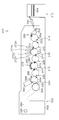
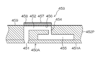
- a diagram showing a configuration example of an inkjet recording apparatus 29A is a plan perspective view showing an example of the structure of the head, and FIG. 29B is a partially enlarged view of part. Plane perspective view showing another structural example of the head Sectional view along line 31-31 in part (A) of FIG.
- the non-discharge correction technology changes the dot pattern at the image position corresponding to the nozzles in the vicinity of the non-discharge nozzles in the recording head, so that the non-discharge portions (streaky image defects) caused by the non-discharge nozzles are not discharged.
- This is a correction technique that compensates for dot recording by ejection from nozzles other than nozzles and reduces the visibility of image defects.
- the first method is a method of obtaining a corrected halftone image by performing correction processing on a multi-tone input image and performing halftone processing on the corrected image data.
- the second method is a method of obtaining a corrected halftone image by applying correction for correcting the dot arrangement to a halftone image obtained by halftone processing of an input image.
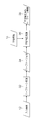
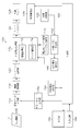
- FIG. 1 is a block diagram showing a flow of undischarge correction processing according to the first method.
- the discharge failure correction method 16 according to the first method uses discharge failure information 14 indicating the position of discharge failure nozzles for discharge image correction processing 16 for an input image 12 captured as original image data representing the image content to be printed. I do.
- the data format of the input image 12 is not particularly limited, here, for the sake of simplicity, it is assumed that the input image 12 is a gradation image having the same color type, number of colors, and resolution as the ink color used in the inkjet printing system. .
- the image data is 8 bits (256 bits) for each color of CMYK.
- Image data having (gradation).
- Undischarge information 14 is information indicating the position of the undischarge nozzle in the recording head of the ink jet printing system (“position information of undischarge nozzle”).
- position information of undischarge nozzle The position information of the undischargeable nozzle that cannot be used for image recording can be specified from the output result of the test pattern.
- the identified undischarge nozzle position information is stored as undischarge information 14 in an undischarge information storage unit such as a memory.
- the undischarge correction process 16 the image data at the image position in the vicinity of the undischarge nozzle is corrected, and an undischarge corrected image 18 which is corrected multi-tone image data is obtained.
- a halftone process 20 is performed on the discharge failure correction image 18 thus obtained, and a halftone image 22 which is image data representing a dot pattern is obtained.
- the halftone process 20 generally quantizes multi-tone image data of M values (M is an integer of 3 or more) and has N values (N is an integer of 2 or more and less than M) that can be recorded by the recording head. It is a process of converting to data.
- M is an integer of 3 or more
- N is an integer of 2 or more and less than M
- It is a process of converting to data.
- an image signal of 8 bits ⁇ (256 gradations) for each color of CMYK is converted into a signal (dot data) representing a multi-value dot arrangement of three or more values in pixel units.
- the halftone process 20 is performed with multiple gradations (for example, 4) “Discharge large droplet ink”, “Discharge medium droplet ink”, “Discharge small droplet ink”, “Do not discharge (no droplet)”
- a dither method, an error diffusion method, or the like is applied to such halftone processing. Large dots are formed on the recording medium by ejecting large drops, medium dots are formed by ejecting medium drops, and small dots are formed by ejecting small drops.
- the halftone image 22 generated through the halftone process 20 becomes dot data reflecting the gradation correction of the discharge failure correction process 16. That is, in the first method, undischarge correction is performed at the data stage of the continuous tone image before halftone processing, and the signal value (gradation value) corresponding to the image position near the undischarge nozzle is increased. A halftone image 22 corrected by the procedure of performing the halftone process 20 on the discharge failure correction image 18 is obtained.
- the process of performing the undischarge correction process 16 corresponds to the “undischarge correction process process”, and the process of performing the halftone process 20 corresponds to the “halftone process process”.
- the undischarge correction function is realized by combining the undischarge correction process 16 and the halftone process 20.
- FIG. 2 is a block diagram showing the flow of undischarge correction processing by the second method.
- the undischarge correction method according to the second method converts the input image 12 that is the original image data into a multi-value halftone image 34 by a halftone process 32, and then performs an undischarge operation on the halftone image 34.
- the discharge failure correction process 36 is performed using the information 14.
- the undischarge correction process 36 a correction process is performed in which the ink amount of dots corresponding to the adjacent nozzles of the undischarge nozzle is corrected.
- a discharge failure corrected halftone image 38 which is dot data after discharge failure correction is obtained.
- the second method performs the halftone process before the undischarge correction, and performs the undischarge correction on the halftone image after the halftone process, thereby performing the undischarge corrected halftone image 38. Have gained.
- the process of performing the halftone process 32 corresponds to the “halftone process process”, and the process of performing the undischarge correction process 36 corresponds to the “undischarge correction process process”.
- the discharge failure correction function is realized by the discharge failure correction process 36.
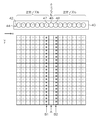
- FIG. 3 is a schematic diagram of the discharge failure correction image 18
- FIG. 4 is a schematic view of a halftone image 22 that is a halftone processing result of the discharge failure correction image 18.
- reference numeral 40 denotes a line-type recording head (line head) in the single-pass inkjet printing system.
- the recording head 40 includes a plurality of nozzles 42 for ejecting ink droplets.
- the vertical direction in FIG. 3 is the paper feeding direction, which is called “y direction” or “sub-scanning direction”.
- a nozzle row 44 in which a plurality of nozzles 42 are arranged in a line along the x direction is depicted.
- the nozzles are not necessarily arranged in a line.
- the number of nozzles, nozzle density, and nozzle arrangement in the recording head are not particularly limited, and there may be various forms.
- a one-dimensional nozzle array in which a large number of nozzles are arranged on a straight line (in a line) at a constant interval may be used.
- a so-called staggered arrangement may be employed in which each nozzle row is shifted in the nozzle row direction by a half pitch of the nozzle interval (inter-nozzle pitch). Further, in order to achieve higher recording resolution, a configuration in which a large number of nozzles are two-dimensionally arranged on the ink ejection surface (nozzle surface), such as a matrix arrangement in which three or more nozzle rows are arranged, can be employed. .
- the projected nozzle array in which the nozzles in the two-dimensional nozzle array are projected (orthographically projected) so as to be aligned along the medium width direction (corresponding to the main scanning direction)
- medium width direction corresponding to the main scanning direction
- equal intervals means substantially equal intervals as the droplet ejection points that can be recorded by the ink jet printing system.
- the concept of “equally spaced” also includes cases where the intervals are slightly different in consideration of manufacturing errors and movement of droplets on the medium due to landing interference.
- nozzle positions can be associated with the order of projection nozzles arranged along the main scanning direction.
- the term “nozzle position” refers to the position of the nozzle in this substantial nozzle row.
- the positional relationship in the substantial nozzle row is expressed. Since the nozzle position can be expressed as an x coordinate, the nozzle position can be associated with a position in the x direction (x coordinate).
- the total number of nozzles constituting the nozzle row 44 is appropriately designed according to the recording resolution and the drawable width.
- the eighth nozzle from the left among the plurality of nozzles 42 constituting the nozzle row 44 is an undischargeable nozzle 46 that cannot be discharged, and the other nozzles are normal nozzles that can be discharged.
- the x-direction pixel position corresponding to the position (nozzle number k) of the undischarge nozzle 46 cannot record a dot.
- the pixel line along the y direction at the corresponding position is a streak generating part in which a white streak (recording defective part) occurs on the print image.
- the first correction nozzle 47 (nozzle number k-1) and the second correction nozzle 48 (nozzle number k + 1) adjacent to the left and right with the undischarge nozzle 46 interposed therebetween.
- a pixel position (position indicated by arrows B1 and B2) corresponding to is used as an undischarge correction unit, and correction processing for increasing the gradation value of the pixel corresponding to the undischarge correction unit in the input image (continuous tone image) is performed. .
- the brightness display (display by shading) of each cell of the pixel grid shown in FIG. 3 reflects the magnitude of the gradation value, and the higher the gradation value, the darker the color is displayed.
- the gradation value of the pixel position corresponding to the first correction nozzle 47 and the second correction nozzle 48 of the discharge failure correction unit is changed to a value higher than the gradation value of the peripheral part (normal part) which is the non-correction part. ing.
- FIG. 4 is an example of a halftone process result obtained by performing a halftone process on the corrected image data shown in FIG. 3 (corresponding to the undischarge corrected image 18 in FIG. 1).
- the higher the gradation the larger the number of dots and the larger the dots appear. Therefore, as shown in FIG. 4, large dots are arranged in the discharge failure correction unit. As a result, the streak due to the undischarge nozzle 46 becomes difficult to see.
- the undischarge correction process by the first method has been described, but as a result, the dot pattern as shown in FIG. 4 can also be created by the undischarge correction process by the second method.
- FIGS. 3 and 4 an example is described in which correction is performed with two nozzles, the first correction nozzle 47 and the second correction nozzle 48 adjacent to both sides of the discharge failure nozzle 46, but the range of nozzles used for correction Is not limited to these two nozzles.
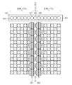
- FIG. 5 shows an example in which the dot pattern in the peripheral part (normal part) other than the correction part is similar to the dot pattern in the discharge failure correction part.
- FIG. 5A shows the dot pattern of the peripheral portion
- FIG. 5B shows the dot pattern of the discharge failure correction portion.
- the pattern is such that dots on (with dots) and dots off (without dots) are alternately repeated along the pixel rows arranged in the y direction.
- the average ink amount of the correction portion including the non-discharge portion (streak generation portion) corresponding to the non-discharge nozzle and the non-discharge correction portion corresponding to the two correction nozzles adjacent to the non-discharge nozzle, and the non-correction portion is equivalent to the average ink amount in the peripheral portion.
- Part (C) of FIG. 5 is a combination of the peripheral dot pattern shown in part (A) of FIG. 5 and the undischarge correction part dot pattern shown in part (B) of FIG.
- amendment process is shown.
- part of FIG. 5 shows the visual appearance of the printing result by the dot pattern of part (C) of FIG. Part (D) of FIG. 5 performs a filtering process that applies a visual transfer function (VTF) corresponding to the visual characteristics of the human eye to the dot pattern of part (C) of FIG. Obtainable.
- VTF visual transfer function
- FIG. 6 shows a case where the dot pattern in the peripheral portion is different from the dot pattern in the discharge failure correction portion.
- FIG. 6A shows the dot pattern of the peripheral portion
- FIG. 6B shows the dot pattern of the discharge failure correction portion.
- the (A) part of FIG. 6 is equivalent to the (A) part of FIG.
- the part (B) in FIG. 6 is different from the part (B) in FIG. 5 in the dot arrangement structure in the discharge failure correction unit. That is, the dot pattern of the discharge failure correction unit in the portion (B) of FIG. 6 is a pattern in which three dots continuously on in the y direction and three dots continuously off are repeated periodically.
- the dot pattern in the peripheral portion is a pattern in which dots on and dots are alternately repeated in units of one pixel in the y direction, and both patterns are greatly different.
- the average ink amount of the correction part including the non-discharge part (streak generation part) corresponding to the non-discharge nozzle and the non-discharge correction part corresponding to two correction nozzles adjacent to the non-discharge nozzle, and the non-correction part This is equivalent to the average ink amount in the peripheral portion.
- (C) part of FIG. 6 is a pattern combining the dot pattern of the peripheral part shown in part (A) of FIG. 6 and the dot pattern of the discharge failure correction part shown in part (B) of FIG. The dot arrangement of the halftone image obtained through the undischarge correction process is shown.
- part of FIG. 6 shows the visual appearance of the printing result by the dot pattern of part (C) of FIG.
- the part (D) in FIG. 6 can be obtained by performing filter processing corresponding to the visual characteristics on the dot pattern in the part (C) in FIG.
- the average ink amount for each pixel row arranged in the y direction before and after the correction as in the portion (D) in FIG. is seen as an unnatural texture.
- Such a phenomenon is remarkable when gradation expression is performed by a cluster structure pattern in which dots are arranged in an agglomerated manner, such as AM screen processing or cluster type halftone processing.
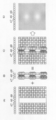
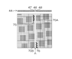
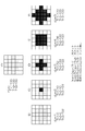
- FIG. 7 is an explanatory diagram showing an example of a recording failure due to an undischarge nozzle in an AM network.
- the upper left diagram in FIG. 7 represents a dot pattern of a normal image without discharge nozzles (an image without discharge failure).
- This cluster of dots (dot aggregation portion) is called a cluster.
- an example of an AM network in which clusters 70 that are clusters of dots of 4 ⁇ 4 pixels are regularly arranged is shown.
- the upper right diagram in FIG. 7 shows the visual appearance of the printed result using the dot pattern in the upper left diagram.
- the lower left diagram in FIG. 7 shows a dot pattern of an image without undischarge correction (uncorrected image) when the discharge failure nozzle 46 exists in the nozzle row 44 and discharge failure correction is not performed.
- the lower right diagram in FIG. 7 shows the visual appearance of the print result by the dot pattern in the lower left diagram.
- the leftmost 4 dots of the cluster indicated by reference numeral 70A cannot be recorded, and the rightmost 4 dots of the cluster indicated by reference 70B cannot be recorded. If the discharge failure correction is not performed for the discharge failure nozzle 46, the amount of ink is insufficient and a white streak is visually recognized as indicated by broken lines 72A and 72B in the lower right diagram of FIG. .
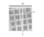
- FIG. 8 is an explanatory diagram of an example of occurrence of artifacts due to undischarge correction in the AM network.
- the left diagram in FIG. 8 is an example of a dot pattern in which discharge failure correction is performed on the discharge failure nozzle 46.
- this figure shows an example (comparative example) in the case where correction is made with characteristics different from the phase and cycle of the AM network without considering the relationship with the arrangement structure of the clusters in the peripheral portion at the time of discharge failure correction.
- Reference numerals 75 and 76 denote dots added by the discharge failure correction.
- the same number of dots as the number of dots that cannot be printed by the discharge nozzle 46 (eight) is added by the correction nozzles 47 and 48 on both sides of the discharge nozzle 46. That is, with respect to the pixel positions corresponding to the right and left correction nozzles 47 and 48 across the discharge failure nozzle 46, four dots 75 and 76 are added to the white background portion before correction (dot off portion between clusters), respectively. It has been made. The added dots 75 and 76 are arranged in a distributed manner so that the dots are distributed almost evenly in the correction portions at the pixel positions corresponding to the correction nozzles 47 and 48, and the ink amount is approximately preserved before and after the correction. As described above, the number of dots and the dot size are determined.
- the right figure in FIG. 8 shows the visual appearance of the print result by the dot pattern in the left figure in FIG.
- the visibility of the streaks is reduced compared to the lower right diagram of FIG. 7, but compared to the upper right diagram of FIG. 7, the portion where dots are not originally placed (the portion that was originally white) Since the additional dots 75 and 76 are placed on the printed matter, when the printed matter is observed close up (for example, when the printed matter is observed at a short distance of about 150 mm to 200 mm), the dot arrangement is visually recognized as a texture, and the correction portion cluster is darkened. appear.
- the user who observes at a short distance gives a sense of incongruity to the undischarge correction portion.
- the dot arrangement after the undischarge correction is visually recognized as a texture, which gives a sense of incongruity to the graininess.
- the non-discharge part is not limited to the dot pattern missing from the non-discharge nozzle 46 (recording defective part). It is also conceivable to perform non-discharge correction such that additional dots 75 and 76 are arranged in a coherent manner near the clusters 70A and 70B with the (streaks generation unit) interposed therebetween.
- Such a problem is not limited to the AM network, but also applies to the cluster type halftone in which dots are arranged in an agglomerated manner.
- the cluster type halftone is not as regularly arranged as the AM network, but has a pattern characteristic similar to that of the AM network in that two or more dots are continuously and aggregated in the nozzle arrangement direction.
- AM network and cluster type halftone originally have very few high-frequency components in the spatial frequency, if high-frequency components are generated in the non-correction part as a result of discharge failure correction, they are easily recognized as artifacts ([Problem 1-1] ).
- the dot pattern of the discharge failure correction part is similar to the dot pattern of the peripheral part An unnatural texture (artifact) can be suppressed by setting the pattern to be made.
- FIG. 10 is a diagram showing an example of a halftone image obtained by applying undischarge correction according to the embodiment of the present invention. 10 solves [Problem 1] and [Problem 1-1] and [Problem 1-1-1] included in the white streak caused by the discharge failure nozzle 46 described in the lower part of FIG. This is an application of an undischarge correction method capable of
- the structure of the cluster 70 in the halftone image before correction is maintained, and dots are not arranged in the originally white background. 46, the dots 71A and 71B in the clusters 70A and 70B that are defective in recording are corrected to increase the dot size (increase the ink droplet amount).
- the right diagram in FIG. 10 is obtained by performing a filtering process considering the visual characteristics on the left diagram in FIG.
- the right figure in FIG. 10 looks very similar to the upper right figure in FIG. 7, and good correction is realized.
- [Problem 1] was approximated by considering the characteristics (local pattern characteristics) of the dot arrangement structure around the correction area in the halftone pattern when non-discharge correction was not applied (similar) It is preferable to determine the dot pattern of the discharge failure correction unit so as to be a pattern.
- an index of similarity for example, a simple difference sum between image data to be compared, a square sum of differences (SSD: Sum : of Squared Difference), a normalized cross-correlation (NCC), or the like may be used. It can. A specified value that defines an allowable range of similarity that does not affect the visibility is determined, and undischarge correction is performed to generate a dot pattern in which the similarity is equal to or less than the specified value before and after correction.
- SSD Sum : of Squared Difference
- NCC normalized cross-correlation
- the dot-off portion is 2 pixels in the non-correction portion, whereas the dot-off portion is 1 pixel in the correction portion. Due to the difference in the repetition period between the dot-on part and the dot-off part, the correction part appears to be connected.
- the cluster edge is undischarged, the pixel position in the cluster near the edge is corrected to be stronger, and when non-discharge occurs inside the cluster, the correction intensity is weaker than the correction intensity for the edge. It is preferable to correct by the above. Examples of specific means for solving the problem 2 will be described later.
- the first embodiment an example of undischarge correction in which tone correction is performed on an image before halftone processing will be described. That is, the first embodiment is an aspect of the discharge failure correction method according to the first method described in FIG.
- the dither method is a method of determining dot on / off by comparing a threshold value given to each pixel by a dither matrix and a gradation value of image data.
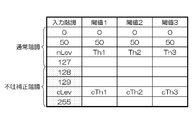
- FIG. 12 is a conceptual diagram of an area division lookup table (LUT).
- the first column (leftmost column) in FIG. 12 represents the input gradation, and here, a value of 8-bit gradation (gradation value 0 to 255) is used.
- a boundary approximately in the middle of the gradation area for example, “127” as a boundary, the discharge correction gradation is set above “127”, and the normal gradation is set below “127”. That is, the range of gradation values 0 to 127 is “normal gradation”, and the range of gradation values 128 to 255 is set to “undischarge correction unit gradation”.
- Three levels of threshold values are set for each gradation value.
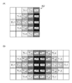
- FIG. 13 is an explanatory diagram of a region classification method using a dither matrix.
- a dither matrix 80 of 5 rows ⁇ 5 columns is shown, but this is the actual dither matrix size (number of elements) that is a part of the dither matrix actually used. Can design any size, such as 192x192, 400x500.
- a value in the range of 0 to 255 is defined for each cell (element) of the dither matrix 80.
- the magnitude of the value of the element is represented by brightness, and white represents 0, black represents 255, and gray represents a value in between.
- the position of each cell in the dither matrix 80 is expressed as (u, v) using the row number u and the column number v.
- the dither matrix 80 has a distribution such that the value gradually increases from the center cell (3, 3) toward the outer periphery. If the value of the element of the dither matrix 80 is x, for example, it can be divided into four types of regions (regions 1 to 4) using three types of threshold values (Th1 ⁇ Th2 ⁇ Th3). That is, the region 1 is a region that satisfies the condition x ⁇ Th1. As shown in the part (B) in FIG. 13, the region 1 has a center (3, 3) and four positions (3, 2), (3,4), (2, 3) on the top, bottom, left and right. , (4, 3).
- Area 2 is an area that satisfies the condition of Th1 ⁇ x ⁇ Th2. As shown in part (C) of FIG. 13, the region 2 is in contact with the outside of the region 1 (1,3), (2,2), (2,4), (3,1), (3 , 5), (4, 2), (4, 4), and (5, 3).
- Area 3 is an area that satisfies the condition of Th2 ⁇ x ⁇ Th3. As shown in the part (D) in FIG. 13, the region 3 touches the outside of the region 2 (1,2), (1,4), (2,1), (2,5), (4, 1) It is composed of 8 pixels including (4,5), (5,2) and (5,4).
- Region 4 is a region that satisfies the condition of Th3 ⁇ x.
- the region 4 includes (1,1), (1,5), (5,1), and (5,5) that are in contact with the outside of the region 3 as shown by the portion (E) in FIG. Consists of pixels.
- the shape of each region can be changed by changing the threshold values Th1, Th2, and Th3 for each gradation.
- the overall dot arrangement state (whether the dot is placed or not It is possible to change only the type of dot used (for example, the type of large dot, medium dot, and small dot) without changing the state.
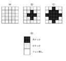
- FIG. 14 is an explanatory diagram showing an example of an operation that can be performed by changing the dot type for each region.
- 14A shows a pattern when the regions 1 and 2 described in FIG. 13 are “small dots (small droplets)” and the regions 3 and 4 are “no dots (no droplets)”.
- 14B shows a pattern when the area 1 is “large dot (large drop)”, the area 2 is “small dot”, and the areas 3 and 4 are “no dot”.
- FIG. 14C shows a pattern when the areas 1 and 2 are “large dots” and the areas 3 and 4 are “no dots”.
- various dot patterns can be generated by combining the region dividing method using the dither matrix 80 and the method of changing the dot type for each region.
- the cluster shape can be manipulated for each gradation. Also, the dot type to be output can be determined for each region.
- the dots used in the cluster without changing the overall dot arrangement state ie, the cluster shape.
- the type of can be changed. That is, it is possible to change only the dot type in the cluster without changing the cluster structure (dot on position) by designing the halftone process (reference numeral 20 in FIG. 1).
- the input gradation includes “normal gradation” used for the normal part (non-correction part) and “undischarge correction gradation” used for the undischarge correction part.
- a correction gradation value (non-discharge correction value) when performing non-discharge correction for a pixel having a normal gradation value of nLev is previously optimized and determined for each nozzle. This is the discharge correction gradation cLev.
- discharge failure correction gradation Since the optimum value of the discharge failure correction value differs depending on the nozzle position, a test pattern that simulates the discharge failure nozzle position is output, and the discharge failure correction gradation optimized for each nozzle is determined in advance. deep.
- a method for obtaining the optimum discharge failure correction value (discharge failure correction gradation) for example, a method described in JP 2012-071474 A can be used.
- a correspondence relationship that the non-discharge correction gradation cLev is applied at the time of non-discharge correction to the normal gradation nLev is determined in advance.
- the gradation of the image data is corrected with reference to the correspondence relationship.
- a dot pattern is defined by halftone processing corresponding to the input gradation of the image data.
- the total dot generation amount here is approximately equal between nLev and cLev.
- FIG. A portion (A) in FIG. 15 represents a dot pattern in the normal gradation nLev.
- the dot pattern corresponding to the normal gradation nLev 52% of small dots are recorded in a 5 ⁇ 5 pixel area (small dots are arranged in 13 out of 25 pixels). Both medium dots and large dots are 0%.
- the total amount of dots generated here represents the ratio of the number of dots placed with respect to the number of pixels of the matrix size as a percentage, and represents the dot recording rate with respect to the number of pixels of the matrix size.
- FIG. 15B to FIG. 15F show examples of how to provide a non-discharge correction gradation dot pattern with respect to the normal gradation.
- the total amount of dots generated in the discharge failure correction gradation cLev is made to be close to 52% in total.
- the breakdown of the dot type ratio that achieves a recording rate of around 52% is not a problem. That is, regardless of the dot types of small dots, medium dots, and large dots, the number of dots need only be noted and it may be in the vicinity of 52%.
- area 1 (0 ⁇ x ⁇ Th1) is a large dot
- area 2 (Th1 ⁇ x ⁇ Th2) is a large dot
- area 3 (Th2 ⁇ x ⁇ Th3) is a small dot. If the dot type for each region is defined in such a manner that the region 4 (Th3 ⁇ x ⁇ 255) has no dots, the total number of the regions 4 (F) to (F) in FIG. It is possible to change the dot pattern to be generated without changing the dot amount (total dot generation amount).
- the undischarge correction gradation corresponding to the normal gradation nLev is defined in the gradation range from cLev1 to cLev2, and cLev1 to cLev2 In the gradation within the range, the total dot generation amount is set to be approximately equal.
- the difference in the total amount of dot generation is within 5%. If the difference in the total amount of dots generated is within 5%, it is considered that the change (difference) in the cluster shape does not substantially affect the visibility, and this level of difference is acceptable.
- Second Embodiment Next, a specific example for dealing with [Problem 2] will be described.
- the second embodiment an example of undischarge correction in which gradation correction is performed on an image before halftone processing will be described. That is, the second embodiment is an aspect of the discharge failure correction method according to the first method described in FIG.
- clusters are sequentially formed from the inside of the cluster in the nozzle array direction toward the cluster end as the tone shifts from low to high. In such a case, it is possible to increase the correction intensity at the cluster end by controlling the discharge failure correction gradation so that a larger dot appears at the cluster end.
- FIGS. 16 to 20 are explanatory diagrams of a method of changing the correction intensity of the correction unit by designing the dither matrix.
- 16A shows a part of a dither matrix used for cluster type halftone processing.
- the size of the element value in the dither matrix 82 is displayed in terms of brightness, and the condition of Th1 ⁇ Th2 ⁇ Th3 ⁇ 255 is satisfied.
- the horizontal direction of the dither matrix 82 is the “nozzle arrangement direction” (nozzle arrangement direction).
- the cluster gradually grows from the inside of the cluster in the nozzle arrangement direction toward the cluster end as the input gradation value changes from the low gradation to the high gradation (
- the dots are arranged so that the cluster of dots is expanded.
- a dither matrix is created in which the element values change stepwise from the inside of the cluster toward the end.
- Th1, Th2, Th3 and “255” are shown for simplicity of explanation.
- image gradation such as 8 bits or 10 bits. The values are distributed.
- part of FIG. 16 shows a part forming the left half of the cluster.
- the elements of the dither matrix constituting one cluster are configured such that the elements of the matrix in the part (A) of FIG. 16 appear symmetrically.
- the actual dither matrix is configured such that elements such as part (B) of FIG. 16 are further arranged periodically.
- FIG. 17 is an explanatory diagram when no discharge nozzle is present.
- the region 1 (0 ⁇ x ⁇ Th1) has no dots
- the region 2 (Th1 ⁇ x ⁇ Th2) has small dots
- the region 3 The dot generation method of each region is set so that small dots are generated in Th2 ⁇ x ⁇ Th3) and small dots are generated in region 4 (Th3 ⁇ x ⁇ 255).
- the halftone process is performed by applying the dither matrix 82 of FIG. 16
- a dot pattern in which small dots are aggregated to form a cluster as shown by reference numeral 84 in FIG. 17 is obtained.
- the dot pattern to be generated is made different depending on the position of the undischarge nozzle in the nozzle array 44 of 5 nozzles.
- FIG. 18 is an explanatory diagram of a method of changing the correction intensity of the correction unit depending on the position of the discharge failure part.
- the area 1 (0 ⁇ x ⁇ Th1) has no dots
- the area 2 (Th1 ⁇ x ⁇ Th2)
- the dot generation method of each area is set so that large dots, medium dots in area 3 (Th2 ⁇ x ⁇ Th3), and medium dots in area 4 (Th3 ⁇ x ⁇ 255) are generated.
- the size of the dot is displayed by brightness, and the darker the color, the larger the dot.
- the part (D) of FIG. 18 shows the correspondence between the dot type and the brightness display in the parts (A) to (C) of FIG. 17 and FIG.
- FIG. 18A shows a case where the second nozzle from the left in the nozzle row 44 is a discharge failure nozzle.
- a position corresponding to the discharge failure nozzle is a streak generation unit.
- Two nozzles adjacent to both sides serve as correction nozzles.
- pixels that were originally white (no dots) are left without dots.
- FIG. 18B shows a case where the third nozzle from the left in the nozzle row 44 is a discharge failure nozzle.
- a large dot is placed at “Th1” in (2, 2) and (2, 4), and a medium dot is placed at “Th2” in (2, 3).
- medium dots are placed in all the fourth pixel columns from the left.
- FIG. 18C shows a case where the fourth nozzle from the left in the nozzle row 44 is a discharge failure nozzle.
- large dots are placed at “Th1” in (3,1) and (3,5), and medium dots are placed in the remaining correction portions.
- a correction pattern corresponding to the discharge failure position can be developed. That is, a large dot is generated at the end of the cluster, and a medium dot is generated when going inside the cluster.
- the correction strength is automatically applied between the end and the inside without determining the position of whether the correction unit is the end or the inside of the cluster. Can be made to change.
- the second embodiment it is possible to change the correction strength between the end portion and the inside of the cluster, and the correction strength is automatically increased and the correction strength is decreased inside the cluster as it goes to the end portion of the cluster.
- Such an undischarge correction function can be realized.
- a correction dot conversion table corresponding to the distance from the cluster end in the nozzle arrangement direction is designed in advance, and for each of the correction unit pixels of the given halftone image, the cluster end After calculating the distance from, a process of replacing with a correction dot is performed with reference to the correction dot conversion table according to the type of each dot before correction.
- FIG. 19 represents a halftone image before correction. Similar to FIG. 17, a 5 ⁇ 5 pixel range is shown. It is assumed that the third nozzle from the left in the nozzle row 44 is an undischarge nozzle. In the halftone image 84 before correction, dots are also assigned to pixel positions (undischarge portions) corresponding to undischarge nozzles.
- the pixel distance from the cluster end is calculated in the lateral direction (nozzle arrangement direction).
- (B) in FIG. 19 represents the distance from the cluster edge in units of pixels (px).
- the pixel at the end (boundary) of the cluster has a distance “0”, and the distance from the end gradually increases as the distance from the end becomes 1 ⁇ 2 ⁇ 3.
- the distance is measured from the left to the right, but the distance can also be measured from the right to the left of the cluster. It is only necessary to calculate the distance from both the left and right directions and adopt a short distance.
- the distance from the cluster end is calculated in units of pixels, but the unit of distance is not limited to this, and any index value may be used as long as it is an index indicating distance.
- the distance can be expressed using an appropriate function.
- 19C is an example of the corrected halftone image 85 in which the correction for changing the dot type is performed according to the distance from the cluster end.
- the size of the dot is displayed in terms of brightness, and the darker the color, the larger the dot.
- the part (D) in FIG. 19 shows the correspondence between the dot type and the brightness display.
- FIG. 20 is an example of a correction dot conversion table.
- the horizontal axis indicates the dot type before correction, and the vertical axis indicates the dot type after correction.
- the correction dot conversion table actually defines the correspondence before and after the correction of four types of discrete values (dot types), but in FIG. Indicated by.
- the correction dot conversion table of FIG. 20 it is preferable to design the table so that the dots are not switched in a white background where no dots are originally placed.
- the distance from the cluster end of the discharge failure correction unit is obtained for the halftone image, and the dot size is changed with reference to the correction dot conversion table.
- the difference in the total amount of dots before and after correction is allowed to be about 5%
- the control of generating dots with a certain probability (with a generation ratio of 5% or less) with respect to “no dot” before correction is also possible. Is possible.
- the simplest method is to generate 42Y patterns in an exhaustive search, and select the optimal pattern that is most similar to the uncorrected pattern and eliminates streaks after considering visual characteristics. Perform optimization operations on.
- the search range can be narrowed down by restricting the discharge ink amount of the correction nozzle to be close to 1.5 times or by restricting the contour of the cluster to be close.
- FIG. 1 An example of a specific procedure is shown in FIG.
- FIG. 21 is a flowchart showing an example of a correction pattern optimization procedure.
- an image area around the discharge failure portion is extracted from the given halftone image, and a halftone pattern before correction (when there is no discharge failure) is acquired (step S102).
- a pattern of an image area an image area corresponding to the discharge failure correction section
- the process which extracts is performed.
- a correction pattern as a pattern candidate of the discharge failure correction unit is generated for the periphery of the discharge failure part corresponding to the pre-correction dischargeless halftone pattern 92 acquired in step S102 (step S104).
- the correction pattern 94 generated here is a candidate dot pattern arranged in the pixel row corresponding to the two correction nozzles adjacent to both sides of the discharge failure nozzle.
- the pixel row (non-discharge portion) corresponding to the non-discharge nozzle in the correction pattern 94 is “no dot”, and a pattern in which four-value dot types are appropriately assigned to the pixel row adjacent to the non-discharge portion.
- arithmetic processing for superimposing a visual filter corresponding to the visual characteristics is performed on each of the uncorrected undischarge-free halftone pattern 92 and the correction pattern 94 (steps S106 and S108).
- a Dooley-Shaw VTF Vehicle Transfer Function
- step S106 By performing the spatial frequency processing (step S106) on the uncorrected undischargeless halftone pattern 92, the “uncorrected appearance image corresponding to the appearance of the undischarged portion around the undischargeless halftone image before correction” is displayed.
- the data 96 of “im1” is obtained.
- step S108 by performing spatial frequency processing (step S108) on the correction pattern 94, data 98 of “correction portion appearance image im2” corresponding to the appearance of the correction portion is obtained.
- step S110 the similarity S between the appearance image im1 before correction and the appearance image im2 of the correction unit is evaluated.
- An example of a method for calculating the similarity S will be described later.
- step S110 The similarity S calculated in step S110 is compared with a predetermined threshold (specified value) (step S120). If the similarity S is larger than the threshold (if the similarity is lower than the similarity indicated by the threshold). ) Since the correction pattern 94 is not appropriate, the process returns to step S104, a new (other) correction pattern is generated, and the processes of steps S104 to S110 are repeated.
- a predetermined threshold specified value
- step S110 If the similarity S calculated in step S110 is equal to or less than a threshold value (if the similarity is high), the correction pattern 94 is allowed as an appropriate correction pattern, and this is adopted as the dot pattern of the correction unit ( Step S124), the process is terminated.
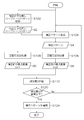
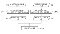
- FIG. 22 is a flowchart illustrating an example of a procedure for evaluating the similarity S.
- the data 96 of the appearance image im1 before correction is averaged in the nozzle row direction (x direction) to create a brightness profile in the paper feed direction (y direction) (step S111).
- the data 98 of the appearance image im2 of the correction unit is averaged in the nozzle row direction (x direction), and a profile in the paper feed direction (y direction) is created (step S112).
- the similarity S is calculated based on the pre-correction profile p1 data 101 created in step S111 and the correction unit profile p2 data 102 created in step S112 (step S114).
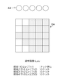
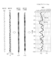
- FIG. 23 is an explanatory diagram schematically showing a generation process of the pre-correction profile p1 and the correction unit profile p2.
- the non-discharge non-discharge halftone pattern 92 is a dot pattern of an image portion (3 pixels in the x direction and image width in the y direction) corresponding to the 3 nozzles of the discharge failure nozzle and the two nozzles on both sides thereof.
- the horizontal direction in the figure is the x direction
- the vertical direction is the y direction.
- the y-direction pixel row (the portion of the pixel row indicated by symbol A) at the pixel position corresponding to the discharge failure nozzle becomes “no dot” due to the inability to record, and the pixel position corresponding to the correction nozzles on both sides thereof.
- This is a pattern in which dots are arranged in the y-direction pixel row (pixel row portions indicated by reference numerals B1 and B2).
- the difference in dot type is displayed in terms of brightness, with white indicating no dots, black indicating large dots, and gray indicating small dots or medium dots.
- a spatial frequency process for superimposing a visual filter is performed, thereby correcting the appearance of each pattern.
- a previous appearance image im1 and a correction portion appearance image im2 are obtained.
- the average image p1 before correction is averaged in the x direction (three pixel columns are averaged) to obtain a pre-correction profile p1 as the y-direction profile before correction.
- the correction unit profile p2 as the y direction profile of the correction unit is obtained by averaging the appearance image im2 of the correction unit in the x direction (average of three pixel columns).
- the graph shown on the right side of FIG. 23 shows the relationship between the position in the y direction and the intensity of the image signal.
- the profile indicated by the thin line is the pre-correction profile p1
- the profile indicated by the thick line is the correction unit profile p2. .
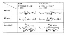
- FIG. 24 shows an example of a method for calculating the similarity S.
- the similarity S for example, simple difference sum, sum of squares of difference (SSD), normalized cross-correlation (NCC), or the like can be used.
- SSD sum of squares of difference
- NCC normalized cross-correlation
- S it may be defined in the real space of the image or may be defined in the Wiener spectrum.
- the calculation formulas for the respective similarities S are as shown in the table of FIG.
- the method for obtaining the optimum pattern in the correction unit is not limited to the above example. Even if it is not based on the full search method, the dot placement can be optimized using the Simulated Annealing method or the Void-and-Cluster method as a solution to the optimization problem. can do.
- FIG. 25 is a block diagram illustrating a configuration of the inkjet printing system according to the first embodiment and the second embodiment.
- the inkjet printing system 110 is a system that performs image recording by a single pass method, and includes an image data input unit 112, a gradation conversion unit 114, an undischarge correction processing unit 118, a halftone processing unit 120, a head driver 122, and a recording head. 124 is provided.
- the inkjet printing system 110 includes a medium conveyance unit 126 that conveys a recording medium (not shown in FIG. 25), an image reading unit 128 that reads an image recorded on the recording medium by the recording head 124, and an image reading unit.
- An image analysis unit 130 that analyzes the read image acquired from 128 is provided.
- the image analysis unit 130 includes a defective nozzle detection unit 132 and an undischarge correction parameter calculation unit 134.
- the defective nozzle detection unit 132 performs a process of detecting the position of the non-ejection nozzle based on the read image of the defective nozzle detection test chart. Further, the defective nozzle detection unit 132 calculates the landing position error of each nozzle based on the read image of the defective nozzle detection test chart, and forcibly causes discharge failure when the landing position error exceeds an allowable value. Designate an undischarge nozzle. Non-ejection nozzles and non-ejection nozzles detected by the defective nozzle detection unit 132 are treated as non-ejection nozzles.
- the undischarge nozzle position information (undischarge information) is stored in the undischarge information storage unit 140.
- the undischarge information storage unit 140 corresponds to an “undischarge information storage unit”, and the step of storing undischarge information in the undischarge information storage unit 140 corresponds to an “undischarge information storage step”.
- the discharge failure correction parameter calculation unit 134 performs a calculation process for determining an image gradation correction value (discharge failure correction parameter) of the adjacent nozzle with respect to the position of the discharge failure nozzle from the read image of the discharge failure correction parameter acquisition test chart.
- the discharge failure correction parameter calculation unit 134 generates discharge failure correction LUTs (corresponding to discharge failure correction parameters) that define correction values for discharge failure correction (discharge failure correction gradations) for each nozzle.
- the discharge failure correction parameter generated by the discharge failure correction parameter calculation unit 134 is stored in the discharge failure correction parameter storage unit 142.
- the inkjet printing system 110 includes a test chart generation unit 150 that generates data of various test charts including a test chart for detecting defective nozzles, a printing condition management unit 152 that manages printing conditions necessary for executing a print job, A control unit 162 that controls the entire system is provided, and a display unit 164 and an input device 166 are connected to the control unit 162.
- the display unit 164 and the input device 166 function as a user interface (UI).
- the input device 166 can employ various means such as a keyboard, a mouse, a touch panel, and a trackball, and may be an appropriate combination thereof.
- the form by which the display part 164 and the input device 166 are comprised integrally is also possible like the structure which has arrange
- the operator uses the input device 166 while viewing the contents displayed on the screen of the display unit 164 to input various information such as input of printing conditions, selection of image quality mode, input / editing of attached information, and information search. And the inkjet printing system 110 can be operated. Further, through the display on the display unit 164, the input content and other various information, the system status, and the like can be confirmed.
- Each unit can be realized by a combination of computer hardware and software used as a control device of the inkjet printing system 110.
- the image data input unit 112, the gradation conversion unit 114, the undischarge correction processing unit 118, the halftone processing unit 120, and the head driver 122 may be mounted as image processing functions on the ink jet recording apparatus (printer) side. It is possible to mount all or part of these image processing units (112 to 122) on the control device side.
- the recording head 124 is a line head having a nozzle row in which a plurality of nozzles are arranged over a length corresponding to the entire width of the drawing area in the medium width direction orthogonal to the conveyance direction of the recording medium (maximum width of the image forming area).
- the medium conveyance direction by the medium conveyance unit 126 is the sub-scanning direction (y direction), and the medium width direction orthogonal to the medium conveyance direction is the main scanning direction (x direction).
- FIG. 25 only one block is shown as the recording head 124 for the sake of simplicity.
- a plurality of recording heads respectively corresponding to a plurality of ink colors.
- CMKY four color inks are used, and a recording head for ejecting each color ink is provided for each color.
- the number of ink colors and combinations thereof are not limited to this example.
- a mode in which light color inks such as light cyan (LC) and light magenta (LM) are added, and a mode in which special color inks such as red and green are used are also possible.
- the ink jet recording head 124 has an ejection energy generating element (for example, a piezoelectric element or a heating element) that generates ejection energy necessary for ink ejection corresponding to each nozzle. I have.
- the recording head 124 ejects ink droplets on demand according to the drive signal and ejection control signal supplied from the head driver 122.
- the image data input unit 112 functions as a data acquisition unit for taking in image data (input image 12) representing image contents to be printed (output) by the inkjet printing system 110.
- the image data input unit 112 can be configured by a data input terminal that takes in image data from an external or other signal processing unit in the apparatus.
- the image data input unit 112 may employ a wired or wireless communication interface unit, or may employ a media interface unit that reads and writes an external storage medium (removable disk) such as a memory card. Alternatively, an appropriate combination of these aspects may be used.
- the image data format of the image to be printed can be various.
- a pre-processing unit (not shown) is used in the preceding stage of the image data input unit 112.
- the image data is input from the image data input unit 112 after being converted into image data of ink color and resolution used in the inkjet printing system 110 by performing processing such as color conversion and resolution change.
- RGB image data represented by red (R), green (G), and blue (B) color signals
- a RIP Raster Image Processor
- An apparatus or the like performs RGB ⁇ CMYK color conversion processing or resolution conversion processing, converts the RGB image data into CMYK image data suitable for the inkjet printing system 110, and then inputs the converted image data to the image data input unit 112.
- the gradation conversion unit 114 converts the image data so that the color development characteristics defined by the inkjet printing system 110 are obtained.
- the gradation conversion unit 114 converts the input CMYK signal (pre-density conversion CMYK signal) into a density-converted CMYK signal in accordance with the gradation conversion LUT specified by the printing condition management unit 152.
- the input CMYK signal (CMYK signal before density conversion) may be converted into a C signal after density conversion, an M signal after density conversion, a Y signal after density conversion, and a K signal after density conversion.
- the notation “LUT” in this specification represents a lookup table.
- the gradation conversion LUT is a table describing the relationship (conversion relationship) of the output signal value to the input signal value.
- the gradation conversion LUT is defined for each type of recording medium used for printing.
- a plurality of gradation conversion LUTs are prepared according to the paper type, and an appropriate LUT is referred to according to the paper to be used.
- Such a gradation conversion LUT is prepared for each ink color.
- a gradation conversion LUT is provided for each color of CMYK.
- the input image 12 fetched from the image data input unit 112 is subjected to gradation conversion processing so that a desired gradation is obtained by the gradation conversion unit 114.
- the gradation converting unit 114 has a density unevenness correction processing function for correcting image data in accordance with the recording characteristics depending on the position (x-direction position) of each nozzle of the recording head 124. That is, the gradation converting unit 114 performs image signal correction for suppressing density unevenness of the print image on the recording medium caused by variations in the ejection characteristics of the nozzles in the recording head 124.
- a density unevenness correction LUT which is a one-dimensional lookup table for correcting density unevenness describing the conversion relationship between the input signal value and the output signal value, is prepared. Signal values are converted using the LUT.
- Undischarge correction processing section The discharge failure correction processing unit 118 corrects the image data using the discharge failure information stored in the discharge failure information storage unit 140 and the discharge failure correction parameter stored in the discharge failure correction parameter storage unit 142. Perform correction processing.
- the halftone processing unit 120 is dot data of N values (N is 3 or more) that can output multi-tone image data by the recording head 124 by a quantization method such as a dither method (so-called digital halftoning processing method). Process to convert to.
- the N-value image data generated by the halftone processing unit 120 is converted in accordance with the nozzle arrangement and output to the head driver 122.
- a drive signal (marking signal) is supplied to the recording head 124 via the head driver 122, and the ink ejection operation of the recording head 124 is controlled.
- the medium transport unit 126 is a means for transporting the recording medium.
- the recording medium is conveyed at a constant speed in the sub-scanning direction (y direction) orthogonal to the longitudinal direction (x direction) of the recording head 124.
- the medium conveyance unit 126 can employ various methods such as a drum conveyance method, a belt conveyance method, and a nip conveyance method.
- the detailed structure of the medium transport unit 126 is not shown, it includes a paper feed roller, a transport motor, a motor drive circuit, and the like.
- a sensor for example, an encoder for detecting the position of the recording medium.
- the medium transport unit 126 corresponds to a relative moving unit that moves the recording medium relative to the recording head 124.
- the image reading unit 128 reads an image recorded on the recording medium by the recording head 124 and converts it into electronic image data (read image data).
- a CCD line sensor can be used as the image reading unit 128.
- the image reading unit 128 of this example is an inline sensor installed in the middle of the medium conveyance path, and reads an image recorded by the recording head 124 during conveyance before paper discharge.
- the image reading unit 128 can read the output results of a density measurement test chart and other test charts described later. Further, the image reading unit 128 can read a print image recorded based on image data to be printed specified in a print job.
- the test chart generation unit 150 has a function of generating data of a defective nozzle detection test chart for detecting defective nozzles and a non-discharge correction parameter acquisition test chart for calculating non-discharge correction parameters.
- the test chart generation unit 150 can generate various test chart data such as density measurement test chart data for obtaining density measurement data necessary for calculating density unevenness correction parameters.
- the test chart generation unit 150 supplies the data of the corresponding test chart to the image data input unit 112 according to the instruction of the control unit 162.
- the defective nozzle detection test chart for example, a so-called “1 on n off” type test chart can be used.
- the “1 on n off” type test chart shows the nozzle numbers in order from the end in the main scanning direction with respect to the arrangement of nozzles constituting one nozzle line in the x direction in one line head.
- the droplet ejection timing is changed for each nozzle number group of AN + B (where N is an integer of 0 or more), and a line group is formed by continuous droplet ejection from each nozzle.
- the line patterns of adjacent nozzles adjacent to each other do not overlap each other, and independent line patterns (for each nozzle) are formed for each nozzle.
- the presence / absence of discharge from each nozzle can be ascertained from the output result of the defective nozzle detection test chart.
- the landing position of each nozzle it is possible to determine that a nozzle having a large landing position error exceeding an allowable value is a discharge bent nozzle.
- a test chart for detecting defective nozzles is recorded in the margin of the recording medium one by one during printing, and this is read by the image reading unit 128 to detect the occurrence of defective nozzles at an early stage, thereby preventing discharge. Undischarge correction processing by processing is applied.
- the discharge chart for acquiring discharge failure correction parameters is a density pattern in which discharge failure correction parameters (correction coefficients) are applied to nozzle positions on both sides adjacent to a nozzle that simulates the presence of discharge failure nozzles (intentionally discharge failure). Contains patches.
- the optimum discharge failure correction parameter can be specified from the drawing result with different discharge failure correction parameter values.
- An appropriate correction value (correction coefficient) can be determined for each nozzle by creating a patch in which the position of the nozzle that simulates non-ejection is changed.
- the print condition management unit 152 manages print job information in which image data to be printed is associated with print condition information.
- the user can input print condition setting information when inputting image data to be printed or after inputting image data.
- the print condition management unit 152 generates print job information in which print condition setting information is associated with image data to be printed, and stores and manages the information for each print job.
- For each print job an output image data name, a recording medium type name (paper type), a medium size, and various parameter information used for image processing are stored in association with each other.
- the print condition management unit 152 sets various parameters and data designated by the print job related to the selection in the corresponding processing unit.
- the undischarge correction function described in the first embodiment and the second embodiment can be realized by the inkjet printing system 110 illustrated in FIG.
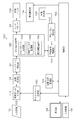
- FIG. 26 is a block diagram illustrating a configuration of an inkjet printing system according to the third embodiment.
- elements that are the same as or similar to the structure shown in FIG. 25 are given the same reference numerals, and descriptions thereof are omitted.
- the inkjet printing system 170 shown in FIG. 26 includes an undischarge correction processing unit 172 for realizing the undischarge correction function described with reference to FIGS. 16 to 18 and correction dot conversion in which a correction dot conversion table is stored.
- the undischarge correction processing unit 172 includes a distance calculation unit 173 that calculates the distance from the cluster end, and a dot replacement unit that performs a dot change process with reference to the correction dot conversion table according to the distance from the cluster end. 174.
- the halftone processing unit 120 in the ink jet printing system 170 may be of any method as long as it generates a halftone image that expresses gradations using AM network or cluster type halftone.
- the discharge failure correction function described in the third embodiment can be realized by the inkjet printing system 170 shown in FIG.
- FIG. 27 is a block diagram illustrating a configuration of an inkjet printing system according to the fourth embodiment.
- elements that are the same as or similar to those shown in FIG. 25 are given the same reference numerals, and descriptions thereof are omitted.
- the inkjet printing system 180 shown in FIG. 27 includes an undischarge correction processing unit 182 for realizing the undischarge correction function described with reference to FIGS.
- the undischarge correction processing unit 182 includes a correction pattern generation unit 183, a visual filter processing unit 184, and a similarity calculation unit 185.
- the correction pattern generation unit 183 performs the correction pattern generation process described in step S104 of FIG.
- the visual filter processing unit 184 performs the spatial frequency processing described in steps S106 and S108 in FIG.
- the similarity calculation unit 185 performs the similarity S calculation process described with reference to FIG.
- a combination of the correction pattern generation unit 183, the visual filter processing unit 184, and the similarity calculation unit 185 corresponds to “a calculation unit that optimizes the pattern of the discharge failure correction unit”.
- the halftone processing unit 120 in the ink jet printing system 180 of FIG. 27 may be of any method as long as it generates a halftone image that expresses gradation by AM network or cluster type halftone.
- the discharge failure correction in consideration of the halftone dot arrangement structure is performed so that the discharge failure correction unit pattern is similar to the peripheral portion, and the above-described artifacts are suppressed. can do.
- an appropriate discharge failure correction intensity can be set according to the distance from the cluster end.
- a program for causing a computer to function is a CD-ROM, a magnetic disk, or other computer-readable medium (tangible object).
- the program can be provided through the information storage medium. Instead of providing the program by storing the program in such an information storage medium, it is also possible to provide the program signal as a download service using a communication network such as the Internet.
- the computer stores a non-discharge information (non-discharge information storage function), a halftone processing function (halftone processing function), and an image defect in a defective recording area due to a defective nozzle. And a function of performing image correction processing (undischarge correction processing function) that reduces the visibility of the image can be realized, and the undischarge correction described in the above embodiment can be performed.
- a part or all of a program for realizing print control including the image processing function for performing the non-discharge correction function and the halftone process for realizing the non-discharge correction function described in the present embodiment is controlled by a host computer or the like. It is also possible to apply to an aspect incorporated in the apparatus or an operation program of a central processing unit (CPU) on the printer (inkjet recording apparatus) side as an image output apparatus.
- CPU central processing unit
- FIG. 28 is a diagram illustrating a configuration example of the ink jet recording apparatus 300.
- the ink jet recording apparatus 300 includes a paper feed unit 312, a treatment liquid application unit 314, a drawing unit 316, a drying unit 318, a fixing unit 320, and a paper discharge unit 322.
- a recording medium 324 that is a sheet is stacked on the paper feed unit 312.
- the recording media 324 are fed one by one from the paper feed tray 350 of the paper feed unit 312 to the processing liquid application unit 314.
- a sheet cut paper
- a configuration in which continuous paper (roll paper) is cut into a necessary size and fed is also possible.
- the processing liquid application unit 314 is a mechanism that applies the processing liquid to the recording surface of the recording medium 324.
- the treatment liquid contains a color material aggregating agent that agglomerates the color material (pigment in this example) in the ink applied by the drawing unit 316. When the treatment liquid comes into contact with the ink, the ink becomes a color material. And the solvent are promoted.
- the processing liquid application unit 314 includes a paper feed cylinder 352, a processing liquid drum 354, and a processing liquid coating device 356.
- the processing liquid drum 354 includes a claw-shaped holding means (gripper) 355 on the outer peripheral surface thereof, and the recording medium 324 is sandwiched between the claw of the holding means 355 and the peripheral surface of the processing liquid drum 354, thereby The tip can be held.
- the treatment liquid coating apparatus 356 can apply various methods such as a spray method and an ink jet method in addition to a roller coating method.
- the recording medium 324 to which the processing liquid is applied is transferred from the processing liquid drum 354 to the drawing drum 370 of the drawing unit 316 via the intermediate transport unit 326.
- the drawing unit 316 includes a drawing drum 370, a sheet pressing roller 374, and ink jet heads 372M, 372K, 372C, 372Y.
- the drawing drum 370 includes claw-shaped holding means (grippers) 371 on the outer peripheral surface thereof, like the processing liquid drum 354. Suction holes are provided on the outer peripheral surface of the drawing drum 370, and the recording medium 324 is sucked and held on the outer peripheral surface of the drum by negative pressure suction.
- a paper conveyance system including the drawing drum 370 corresponds to the medium conveyance unit 126 (see FIGS. 25 to 27).
- Each of the inkjet heads 372M, 372K, 372C, and 372Y is a full-line inkjet recording head having a length corresponding to the maximum width of the image forming area on the recording medium 324, and an image forming surface is formed on the ink ejection surface. A nozzle row in which a plurality of nozzles for ink ejection are arranged over the entire width of the region is formed.
- Each inkjet head 372M, 372K, 372C, 372Y is installed so as to extend in a direction orthogonal to the conveyance direction of the recording medium 324 (the rotation direction of the drawing drum 370).
- the recording medium 324 is transported at a constant speed by the drawing drum 370, and the operation of relatively moving the recording medium 324 and each of the inkjet heads 372M, 372K, 372C, 372Y in this transport direction is performed only once (that is, 1). An image can be recorded in the image forming area of the recording medium 324 in a single sub-scan).
- the ink jet recording apparatus 300 using four colors of CMYK inks is illustrated, but the combination of ink colors and the number of colors is not limited to this embodiment, and the arrangement order of each color head is not particularly limited.
- the recording medium 324 on which an image is formed by the drawing unit 316 is transferred from the drawing drum 370 to the drying drum 376 of the drying unit 318 via the intermediate conveyance unit 328.
- the drying unit 318 is a mechanism for drying moisture contained in the solvent separated by the color material aggregation action, and includes a drying drum 376 and a solvent drying device 378. Similar to the treatment liquid drum 354, the drying drum 376 includes a claw-shaped holding means (gripper) 377 on its outer peripheral surface.
- the solvent drying device 378 includes a plurality of halogen heaters 380 and a hot air jet nozzle 382.
- the recording medium 324 that has been dried by the drying unit 318 is transferred from the drying drum 376 to the fixing drum 384 of the fixing unit 320 via the intermediate conveyance unit 330.
- the fixing unit 320 includes a fixing drum 384, a halogen heater 386, a fixing roller 388, and an in-line sensor 390.
- the fixing drum 384 includes claw-shaped holding means (grippers) 385 on the outer peripheral surface thereof, like the processing liquid drum 354.
- the in-line sensor 390 reads an image (including a density measurement test chart, a defective nozzle detection test chart, an undischarge correction parameter acquisition test chart, etc.) formed on the recording medium 324, and the image density, image defect, and the like. And a CCD line sensor or the like is applied.
- the inline sensor 390 corresponds to the image reading unit 128 described with reference to FIG.
- the paper discharge unit 322 includes a discharge tray 392, and a transfer drum 394, a conveyance belt 396, and a stretching roller 398 are provided between the discharge tray 392 and the fixing drum 384 of the fixing unit 320 so as to be in contact therewith. Is provided.
- the recording medium 324 is sent to the transport belt 396 by the transfer drum 394 and discharged to the discharge tray 392. Although the details of the paper transport mechanism by the transport belt 396 are not shown, the recording medium 324 after printing is held at the front end of the paper by a gripper (not shown) gripped between the endless transport belts 396, and the transport belt 396. Is carried above the discharge tray 392.
- the ink jet recording apparatus 300 of the present example has an ink storage / loading unit that supplies ink to the respective ink jet heads 372M, 372K, 372C, and 372Y, and a treatment liquid applying unit 314. And a head maintenance unit for cleaning each inkjet head 372M, 372K, 372C, 372Y (nozzle surface wiping, purging, nozzle suction, etc.) and a recording medium 324 on the paper transport path.
- a position detection sensor for detecting the position, a temperature sensor for detecting the temperature of each part of the apparatus, and the like are provided.
- FIG. 29A is a perspective plan view showing an example of the structure of the recording head 450
- FIG. 29B is an enlarged view of a part thereof.
- 30 is a perspective plan view showing another example of the structure of the recording head 450
- FIG. 31 is a three-dimensional view of one-channel droplet discharge elements (ink chamber units corresponding to one nozzle 451) serving as recording element units.
- FIG. 30 is a sectional view showing a configuration (a sectional view taken along line 31-31 in FIG. 29).
- the recording head 450 of this example includes a plurality of ink chamber units (droplets) each including a nozzle 451 that is an ink discharge port, a pressure chamber 452 corresponding to each nozzle 451, and the like.
- discharge elements 453 has a two-dimensionally arranged structure, so that a substantial nozzle interval (projection) that is projected (orthographically projected) along the head longitudinal direction (direction orthogonal to the paper feed direction). Nozzle pitch) is increased.
- a nozzle row having a length corresponding to the entire width Wm of the drawing area of the recording medium 324 is configured in a direction (arrow M direction; main scanning direction) substantially orthogonal to the feeding direction (arrow S direction; sub-scanning direction) of the recording medium 324.
- the form to do is not limited to this example.
- short head modules 460A in which a plurality of nozzles 451 are two-dimensionally arranged are arranged in a staggered manner.
- a mode of configuring a line head having a nozzle row having a length corresponding to the entire width of the recording medium 324 by connecting, or a mode of connecting the head modules 460B in a row as shown in FIG. 30 (B). is there.
- the pressure chamber 452 provided corresponding to each nozzle 451 has a substantially square planar shape (see part (A) and part (B) in FIG. 29), and one of the corners on the diagonal line. Are provided with an outlet to the nozzle 451, and an inlet (supply port) 454 for supply ink is provided on the other side.
- the shape of the pressure chamber 452 is not limited to this example, and the planar shape may have various forms such as a quadrangle (rhombus, rectangle, etc.), a pentagon, a hexagon, other polygons, a circle, an ellipse, and the like.
- the recording head 450 has a structure in which a nozzle plate 451A in which nozzles 451 are formed and a flow path plate 452P in which flow paths such as a pressure chamber 452 and a common flow path 455 are formed are laminated and joined. Become.
- the flow path plate 452P constitutes a side wall portion of the pressure chamber 452 and a flow path forming a supply port 454 as a throttle portion (most narrowed portion) of an individual supply path that guides ink from the common flow channel 455 to the pressure chamber 452. It is a forming member.
- the flow path plate 452P has a structure in which one or a plurality of substrates are stacked, although it is illustrated in FIG. 31 in a simplified manner.
- the nozzle plate 451A and the flow path plate 452P can be processed into a required shape by a semiconductor manufacturing process using silicon as a material.
- the common channel 455 communicates with an ink tank (not shown) as an ink supply source, and the ink supplied from the ink tank is supplied to each pressure chamber 452 through the common channel 455.
- a piezoelectric actuator 458 provided with individual electrodes 457 is joined to a diaphragm 456 constituting a part of the pressure chamber 452 (the top surface in FIG. 31).
- the diaphragm 456 of this example functions as a common electrode 459 corresponding to the lower electrode of the piezoelectric actuator 458. It is also possible to form the diaphragm with a non-conductive material such as silicon or resin. In this case, a common electrode layer made of a conductive material such as metal is formed on the surface of the diaphragm member.
- the piezoelectric actuator 458 By applying a driving voltage to the individual electrode 457, the piezoelectric actuator 458 is deformed and the volume of the pressure chamber 452 is changed, and ink is ejected from the nozzle 451 due to the pressure change accompanying this.
- the ink chamber unit 453 having such a structure is constant along the row direction along the main scanning direction and the oblique column direction having a constant angle ⁇ not orthogonal to the main scanning direction.
- the high-density nozzle head of this example is realized by arranging a large number in a grid pattern with the arrangement pattern.
- the arrangement form of the nozzles 451 is not limited to the illustrated example, and various nozzle arrangement structures can be applied.
- the means for generating discharge pressure (discharge energy) for discharging droplets from each nozzle in the recording head is not limited to a piezoelectric actuator (piezoelectric element).
- various pressure generating elements such as heaters (heating elements) in electrostatic actuators, thermal methods (methods that eject ink using the pressure of film boiling by heating of the heaters), and various other actuators
- a discharge energy generating element can be applied.
- Corresponding energy generating elements are provided in the flow path structure according to the ejection method of the head.
- the “recording medium” includes media called by various terms such as a printing medium, a recording medium, an image forming medium, an image receiving medium, and an ejection medium.
- the material, shape, etc. of the recording medium are not particularly limited, and a print on which a resin sheet such as continuous paper, cut paper, seal paper, OHP sheet, film, cloth, nonwoven fabric, wiring pattern, or the like is formed.
- a resin sheet such as continuous paper, cut paper, seal paper, OHP sheet, film, cloth, nonwoven fabric, wiring pattern, or the like is formed.
- Various sheet bodies can be used regardless of the substrate, rubber sheet, and other materials and shapes.
Landscapes
- Engineering & Computer Science (AREA)
- Multimedia (AREA)
- Signal Processing (AREA)
- Quality & Reliability (AREA)
- Physics & Mathematics (AREA)
- Discrete Mathematics (AREA)
- General Physics & Mathematics (AREA)
- Ink Jet (AREA)
- Particle Formation And Scattering Control In Inkjet Printers (AREA)
- Color, Gradation (AREA)
Applications Claiming Priority (2)
| Application Number | Priority Date | Filing Date | Title |
|---|---|---|---|
| JP2013179462A JP6062832B2 (ja) | 2013-08-30 | 2013-08-30 | インクジェット印刷システム及びその不吐補正方法並びにプログラム |
| JP2013-179462 | 2013-08-30 |
Publications (1)
| Publication Number | Publication Date |
|---|---|
| WO2015029789A1 true WO2015029789A1 (ja) | 2015-03-05 |
Family
ID=52586358
Family Applications (1)
| Application Number | Title | Priority Date | Filing Date |
|---|---|---|---|
| PCT/JP2014/071385 Ceased WO2015029789A1 (ja) | 2013-08-30 | 2014-08-13 | インクジェット印刷システム及びその不吐補正方法並びにプログラム |
Country Status (2)
| Country | Link |
|---|---|
| JP (1) | JP6062832B2 (enExample) |
| WO (1) | WO2015029789A1 (enExample) |
Cited By (7)
| Publication number | Priority date | Publication date | Assignee | Title |
|---|---|---|---|---|
| CN107584900A (zh) * | 2016-07-06 | 2018-01-16 | 杭州赛顺数码科技有限公司 | 数码印花机的定位方法及定位数码印花机 |
| US10507647B1 (en) | 2018-01-02 | 2019-12-17 | Landa Corporation Ltd. | Methods and systems for compensating for a malfunctioning nozzle in a digital printing system |
| US10562318B2 (en) | 2017-11-03 | 2020-02-18 | Landa Corporation Ltd. | Method and system for compensating for a malfunctioning nozzle |
| CN113858809A (zh) * | 2020-06-30 | 2021-12-31 | 精工爱普生株式会社 | 印刷装置及印刷方法 |
| CN114953732A (zh) * | 2021-02-25 | 2022-08-30 | 深圳市汉森软件有限公司 | Onepass打印方法、装置、设备及存储介质 |
| CN118055859A (zh) * | 2021-10-18 | 2024-05-17 | 株式会社日立产机系统 | 喷墨记录系统和打印信息修正方法 |
| US12214601B2 (en) | 2020-05-17 | 2025-02-04 | Landa Corporation Ltd. | Detecting a defective nozzle in a digital printing system |
Families Citing this family (5)
| Publication number | Priority date | Publication date | Assignee | Title |
|---|---|---|---|---|
| JP6567312B2 (ja) * | 2015-03-31 | 2019-08-28 | 理想科学工業株式会社 | インクジェット印刷装置 |
| DE102018213105A1 (de) * | 2017-09-05 | 2019-03-07 | Heidelberger Druckmaschinen Ag | Kompensationsmuster für ausgefallene Druckdüsen |
| JP7788810B2 (ja) * | 2020-07-30 | 2025-12-19 | キヤノン株式会社 | 画像処理装置、画像処理方法、及びプログラム |
| JP7537315B2 (ja) * | 2021-03-02 | 2024-08-21 | コニカミノルタ株式会社 | 吐出データ補正装置、画像形成装置および吐出データ補正方法 |
| US12090767B2 (en) | 2022-09-29 | 2024-09-17 | Ricoh Company, Ltd. | Defective nozzle locating mechanism |
Citations (4)
| Publication number | Priority date | Publication date | Assignee | Title |
|---|---|---|---|---|
| JP2000118007A (ja) * | 1998-10-14 | 2000-04-25 | Seiko Epson Corp | 印刷装置、印刷方法および記録媒体 |
| JP2007160563A (ja) * | 2005-12-09 | 2007-06-28 | Canon Inc | インクジェット記録装置及びインクジェット記録方法 |
| JP2007230213A (ja) * | 2006-02-01 | 2007-09-13 | Seiko Epson Corp | 印刷装置、印刷装置制御プログラム及び印刷装置制御方法、並びに印刷用データ生成装置、印刷用データ生成プログラム及び印刷用データ生成方法 |
| JP2011079171A (ja) * | 2009-10-05 | 2011-04-21 | Fujifilm Corp | 画像処理方法、画像処理装置及び画像形成装置 |
Family Cites Families (10)
| Publication number | Priority date | Publication date | Assignee | Title |
|---|---|---|---|---|
| JP2002086767A (ja) * | 2000-09-11 | 2002-03-26 | Sony Corp | プリンタ、プリンタの駆動方法及びプリンタの駆動方法を記録した記録媒体 |
| JP4126384B2 (ja) * | 2004-09-17 | 2008-07-30 | 富士フイルム株式会社 | 画像記録装置及び画像補正方法 |
| JP4039415B2 (ja) * | 2004-09-30 | 2008-01-30 | 富士フイルム株式会社 | ドット配置決定方法及び装置、閾値マトリクスの作成方法、プログラム並びに画像形成装置 |
| JP4670696B2 (ja) * | 2005-03-25 | 2011-04-13 | 富士フイルム株式会社 | 画像処理方法及び装置、閾値マトリクス作成方法、画像形成装置、サブマトリクス作成方法並びにプログラム |
| JP4596174B2 (ja) * | 2005-09-16 | 2010-12-08 | 富士フイルム株式会社 | 画像処理方法及び画像記録装置 |
| JP5398019B2 (ja) * | 2010-09-28 | 2014-01-29 | 富士フイルム株式会社 | 不良記録素子補償パラメータ決定方法及び装置、並びに画像形成装置 |
| JP5619041B2 (ja) * | 2012-01-23 | 2014-11-05 | 富士フイルム株式会社 | 吐出不良検出方法及び装置、画像処理装置、プログラム、並びに印刷システム |
| JP5791155B2 (ja) * | 2012-04-23 | 2015-10-07 | 富士フイルム株式会社 | 画像処理方法、画像処理装置、画像形成装置及びインクジェット記録装置 |
| JP5881576B2 (ja) * | 2012-09-28 | 2016-03-09 | 富士フイルム株式会社 | 画像評価装置、画像評価方法、画像評価システム、及びプログラム |
| JP6018994B2 (ja) * | 2013-08-30 | 2016-11-02 | 富士フイルム株式会社 | インクジェット印刷システム及びその不吐補正方法並びにプログラム |
-
2013
- 2013-08-30 JP JP2013179462A patent/JP6062832B2/ja active Active
-
2014
- 2014-08-13 WO PCT/JP2014/071385 patent/WO2015029789A1/ja not_active Ceased
Patent Citations (4)
| Publication number | Priority date | Publication date | Assignee | Title |
|---|---|---|---|---|
| JP2000118007A (ja) * | 1998-10-14 | 2000-04-25 | Seiko Epson Corp | 印刷装置、印刷方法および記録媒体 |
| JP2007160563A (ja) * | 2005-12-09 | 2007-06-28 | Canon Inc | インクジェット記録装置及びインクジェット記録方法 |
| JP2007230213A (ja) * | 2006-02-01 | 2007-09-13 | Seiko Epson Corp | 印刷装置、印刷装置制御プログラム及び印刷装置制御方法、並びに印刷用データ生成装置、印刷用データ生成プログラム及び印刷用データ生成方法 |
| JP2011079171A (ja) * | 2009-10-05 | 2011-04-21 | Fujifilm Corp | 画像処理方法、画像処理装置及び画像形成装置 |
Cited By (8)
| Publication number | Priority date | Publication date | Assignee | Title |
|---|---|---|---|---|
| CN107584900A (zh) * | 2016-07-06 | 2018-01-16 | 杭州赛顺数码科技有限公司 | 数码印花机的定位方法及定位数码印花机 |
| US10562318B2 (en) | 2017-11-03 | 2020-02-18 | Landa Corporation Ltd. | Method and system for compensating for a malfunctioning nozzle |
| US10507647B1 (en) | 2018-01-02 | 2019-12-17 | Landa Corporation Ltd. | Methods and systems for compensating for a malfunctioning nozzle in a digital printing system |
| US12214601B2 (en) | 2020-05-17 | 2025-02-04 | Landa Corporation Ltd. | Detecting a defective nozzle in a digital printing system |
| CN113858809A (zh) * | 2020-06-30 | 2021-12-31 | 精工爱普生株式会社 | 印刷装置及印刷方法 |
| CN114953732A (zh) * | 2021-02-25 | 2022-08-30 | 深圳市汉森软件有限公司 | Onepass打印方法、装置、设备及存储介质 |
| CN114953732B (zh) * | 2021-02-25 | 2023-03-21 | 深圳市汉森软件有限公司 | Onepass打印方法、装置、设备及存储介质 |
| CN118055859A (zh) * | 2021-10-18 | 2024-05-17 | 株式会社日立产机系统 | 喷墨记录系统和打印信息修正方法 |
Also Published As
| Publication number | Publication date |
|---|---|
| JP2015047725A (ja) | 2015-03-16 |
| JP6062832B2 (ja) | 2017-01-18 |
Similar Documents
| Publication | Publication Date | Title |
|---|---|---|
| JP6062832B2 (ja) | インクジェット印刷システム及びその不吐補正方法並びにプログラム | |
| JP6220029B2 (ja) | インクジェット印刷システム及びその不吐補正方法並びにプログラム | |
| JP5916642B2 (ja) | 画像処理装置及び方法、プログラム並びに画像形成装置 | |
| JP5457307B2 (ja) | 不良記録素子補償パラメータ選定用チャート、不良記録素子補償パラメータ決定方法及び装置、並びに画像形成装置 | |
| JP5458083B2 (ja) | インク使用量評価装置及び方法、プログラム並びにインクジェット装置 | |
| JP7216185B2 (ja) | 画像処理方法及び装置、プログラム並びに画像形成装置 | |
| JP5398019B2 (ja) | 不良記録素子補償パラメータ決定方法及び装置、並びに画像形成装置 | |
| EP3100862B1 (en) | Image-processing apparatus and method, program, and inkjet printing system | |
| JP5189664B2 (ja) | 画像処理装置及び方法、並びに画像形成装置 | |
| JP5855607B2 (ja) | 画像記録方法及び装置並びにプログラム | |
| JP5782739B2 (ja) | 流体噴射装置及び流体噴射方法 | |
| US9064327B2 (en) | Image processing method, image processing device, image forming device and inkjet recording device | |
| JP6064745B2 (ja) | 液体吐出装置及び液体吐出方法 | |
| JP6018994B2 (ja) | インクジェット印刷システム及びその不吐補正方法並びにプログラム | |
| JP5813550B2 (ja) | 色調整方法及び装置、プログラム並びにインクジェット装置 | |
| JP2014004736A (ja) | 画像記録装置、吐出不良検出方法、テストチャートの作成方法及びテストチャートデータ生成プログラム | |
| JP2015003413A (ja) | 印刷方法、印刷制御装置、プログラム並びに印刷システム | |
| JP2014100854A (ja) | 画像形成装置及び方法、並びに補正値算出方法 | |
| JP5545961B2 (ja) | 画像処理方法、画像記録方法及び画像処理装置並びに画像記録装置 | |
| JP6281189B2 (ja) | 液体吐出装置及び液体吐出方法 | |
| JP5702621B2 (ja) | 画像記録装置および画像記録方法 | |
| JP5905804B2 (ja) | 画像処理方法、画像処理装置、画像処理プログラム及び画像記録装置 | |
| JP5855464B2 (ja) | 画素データの補正方法、画像処理装置、プログラム並びに画像形成装置 | |
| JP2015143011A (ja) | インクジェット記録装置および画像処理装置 | |
| JP6282607B2 (ja) | 量子化方法、画像処理装置及び画像記録装置 |
Legal Events
| Date | Code | Title | Description |
|---|---|---|---|
| 121 | Ep: the epo has been informed by wipo that ep was designated in this application |
Ref document number: 14840517 Country of ref document: EP Kind code of ref document: A1 |
|
| NENP | Non-entry into the national phase |
Ref country code: DE |
|
| 122 | Ep: pct application non-entry in european phase |
Ref document number: 14840517 Country of ref document: EP Kind code of ref document: A1 |