WO2015029789A1 - インクジェット印刷システム及びその不吐補正方法並びにプログラム - Google Patents
インクジェット印刷システム及びその不吐補正方法並びにプログラム Download PDFInfo
- Publication number
- WO2015029789A1 WO2015029789A1 PCT/JP2014/071385 JP2014071385W WO2015029789A1 WO 2015029789 A1 WO2015029789 A1 WO 2015029789A1 JP 2014071385 W JP2014071385 W JP 2014071385W WO 2015029789 A1 WO2015029789 A1 WO 2015029789A1
- Authority
- WO
- WIPO (PCT)
- Prior art keywords
- correction
- image
- undischarge
- nozzle
- halftone
- Prior art date
Links
Images


Classifications
-
- H—ELECTRICITY
- H04—ELECTRIC COMMUNICATION TECHNIQUE
- H04N—PICTORIAL COMMUNICATION, e.g. TELEVISION
- H04N1/00—Scanning, transmission or reproduction of documents or the like, e.g. facsimile transmission; Details thereof
- H04N1/40—Picture signal circuits
- H04N1/409—Edge or detail enhancement; Noise or error suppression
-
- B—PERFORMING OPERATIONS; TRANSPORTING
- B41—PRINTING; LINING MACHINES; TYPEWRITERS; STAMPS
- B41J—TYPEWRITERS; SELECTIVE PRINTING MECHANISMS, i.e. MECHANISMS PRINTING OTHERWISE THAN FROM A FORME; CORRECTION OF TYPOGRAPHICAL ERRORS
- B41J2/00—Typewriters or selective printing mechanisms characterised by the printing or marking process for which they are designed
- B41J2/005—Typewriters or selective printing mechanisms characterised by the printing or marking process for which they are designed characterised by bringing liquid or particles selectively into contact with a printing material
- B41J2/01—Ink jet
- B41J2/21—Ink jet for multi-colour printing
- B41J2/2132—Print quality control characterised by dot disposition, e.g. for reducing white stripes or banding
- B41J2/2139—Compensation for malfunctioning nozzles creating dot place or dot size errors
-
- B—PERFORMING OPERATIONS; TRANSPORTING
- B41—PRINTING; LINING MACHINES; TYPEWRITERS; STAMPS
- B41J—TYPEWRITERS; SELECTIVE PRINTING MECHANISMS, i.e. MECHANISMS PRINTING OTHERWISE THAN FROM A FORME; CORRECTION OF TYPOGRAPHICAL ERRORS
- B41J2/00—Typewriters or selective printing mechanisms characterised by the printing or marking process for which they are designed
- B41J2/005—Typewriters or selective printing mechanisms characterised by the printing or marking process for which they are designed characterised by bringing liquid or particles selectively into contact with a printing material
- B41J2/01—Ink jet
- B41J2/21—Ink jet for multi-colour printing
- B41J2/2132—Print quality control characterised by dot disposition, e.g. for reducing white stripes or banding
- B41J2/2146—Print quality control characterised by dot disposition, e.g. for reducing white stripes or banding for line print heads
-
- H—ELECTRICITY
- H04—ELECTRIC COMMUNICATION TECHNIQUE
- H04N—PICTORIAL COMMUNICATION, e.g. TELEVISION
- H04N1/00—Scanning, transmission or reproduction of documents or the like, e.g. facsimile transmission; Details thereof
- H04N1/40—Picture signal circuits
- H04N1/40087—Multi-toning, i.e. converting a continuous-tone signal for reproduction with more than two discrete brightnesses or optical densities, e.g. dots of grey and black inks on white paper
-
- H—ELECTRICITY
- H04—ELECTRIC COMMUNICATION TECHNIQUE
- H04N—PICTORIAL COMMUNICATION, e.g. TELEVISION
- H04N1/00—Scanning, transmission or reproduction of documents or the like, e.g. facsimile transmission; Details thereof
- H04N1/40—Picture signal circuits
- H04N1/405—Halftoning, i.e. converting the picture signal of a continuous-tone original into a corresponding signal showing only two levels
- H04N1/4055—Halftoning, i.e. converting the picture signal of a continuous-tone original into a corresponding signal showing only two levels producing a clustered dots or a size modulated halftone pattern
- H04N1/4057—Halftoning, i.e. converting the picture signal of a continuous-tone original into a corresponding signal showing only two levels producing a clustered dots or a size modulated halftone pattern the pattern being a mixture of differently sized sub-patterns, e.g. spots having only a few different diameters
-
- B—PERFORMING OPERATIONS; TRANSPORTING
- B41—PRINTING; LINING MACHINES; TYPEWRITERS; STAMPS
- B41J—TYPEWRITERS; SELECTIVE PRINTING MECHANISMS, i.e. MECHANISMS PRINTING OTHERWISE THAN FROM A FORME; CORRECTION OF TYPOGRAPHICAL ERRORS
- B41J29/00—Details of, or accessories for, typewriters or selective printing mechanisms not otherwise provided for
- B41J29/38—Drives, motors, controls or automatic cut-off devices for the entire printing mechanism
- B41J29/393—Devices for controlling or analysing the entire machine ; Controlling or analysing mechanical parameters involving printing of test patterns
- B41J2029/3935—Devices for controlling or analysing the entire machine ; Controlling or analysing mechanical parameters involving printing of test patterns by means of printed test patterns
Definitions
- the present invention relates to an inkjet printing system, an undischarge correction method thereof, and a program, and more particularly to an image correction technique for correcting a recording defect due to an undischarge nozzle in an inkjet printing system that performs image recording by a single pass method.
- the inkjet printing system includes a recording head having a plurality of nozzles, and forms an image on a recording medium such as printing paper by controlling an ink ejection operation from each nozzle based on image data to be printed.
- the recording head may generate undischargeable nozzles that cannot be discharged due to nozzle clogging or failure of the discharge energy generating element.
- defective nozzles that cause ejection bends that cause the landing position error to become larger than the allowable value are forcibly discharged so that they are not used for recording, and treated as undischarged nozzles. There is.
- Non-discharge correction is synonymous with “non-discharge correction” and is referred to as “non-discharge correction” in this specification.
- Undischarge correction is realized by changing dots that are ejected from other dischargeable nozzles (non-discharge nozzles) close to the discharge failure nozzle.
- an appropriate condition for correction is that the ink amount is approximately the same before and after the correction. For example, when one nozzle fails to discharge and correction is performed with two nozzles on both sides of the nozzle, the nozzles are supposed to be discharged from the three nozzles, which are the nozzles and the nozzles on both sides. This amount of ink is discharged by two nozzles on both sides.
- the amount of ink ejected from the correction nozzles on both sides of the non-ejection nozzle is about 1.5 times the ink amount of the normal part (non-correction part)
- the density difference between the normal part and the correction part will be reduced.
- the correction part of undischarge correction becomes inconspicuous. Actually, since there is a difference in ejection characteristics for each nozzle, the correction value is given a certain range without strictly increasing the ink amount by a factor of 1.5.
- the present invention has been made in view of such circumstances, and provides an inkjet printing system, an undischarge correction method, and a program that can solve at least one of the above-described problems and realize good undischarge correction. With the goal.
- the ink jet printing system is an ink jet printing system for performing image recording by a single pass method, and cannot be used for image recording among a plurality of nozzles and a recording head.
- a non-discharge information storage unit that stores position information of non-discharge nozzles
- a halftone processing unit that quantizes the input image to generate a halftone image indicating a multi-value dot pattern of three or more values
- an input image On the other hand, with respect to the halftone image, an undischarge correction processing unit that performs an image correction process for reducing the visibility of image defects of the recording failure portion by the undischarge nozzle based on the position information of the undischarge nozzle, And an undischarge correction unit that is close to the recording defect portion based on the dot arrangement structure of the halftone image obtained by the halftone processing unit and the position information of the undischarge nozzle
- An ink jet printing system having an ejection failure correction function for ejection failure correction to generate a dot pattern.
- the non-discharge correction function in the ink jet printing system is realized by a combination of correction processing by the non-discharge correction processing unit and halftone processing by the halftone processing unit, and by a correction process by the non-discharge correction processing unit. possible.
- the halftone processing unit has an AM (Amplitude Modulation) network or two or more dots aggregated in the nozzle arrangement direction of the recording head.
- AM Amplitude Modulation
- a halftone image that expresses gradations using cluster-type halftones can be generated.
- the dot pattern after correction of the non-discharge correction unit generated by the non-discharge correction function is similar to the dot pattern of the non-correction unit It can be configured as a pattern.
- the artifact in the correction part can be suppressed by making the dot pattern after correction of the discharge failure correction part similar to the dot pattern of the non-correction part in the vicinity thereof.
- the image similarity is equal to or less than a specified value before and after correction by the discharge failure correction function. Can do.
- the similarity may be a simple difference sum.
- the similarity may be a sum of squares of differences.
- the similarity may be a normalized cross-correlation.
- a visual frequency response characteristic may be used in evaluating the similarity.
- the frequency response characteristic may be a Dooley-Shaw VTF (Visual Transfer Function) function.
- the undischarge correction processing unit performs the undischarge so that the similarity before and after the correction is equal to or less than a specified value. It can be set as the structure provided with the calculating part which optimizes the pattern of a correction
- the undischarge correction method according to the twelfth aspect is an undischarge correction method for reducing the visibility of an image defect due to a recording defect caused by an undischarge nozzle of an inkjet printing system that performs image recording by a single pass method.
- An undischarge information storage step for storing position information of undischarge nozzles that cannot be used for image recording among a plurality of nozzles in a recording head having a plurality of nozzles, and an input image is quantized to obtain three or more values.
- a halftone processing step for generating a halftone image showing a multi-valued dot pattern, and a recording failure portion due to an ejection failure nozzle based on positional information of the ejection failure nozzle with respect to an input image or a halftone image
- a non-discharge correction processing step for performing image correction processing to reduce the visibility of image defects of the halftone image obtained by the halftone processing step Based on the Tsu preparative arrangement and discharge failure position information of the nozzle, a discharge failure correction method of performing ejection failure correction which generates a dot pattern of discharge failure correction unit close to the recording failure portion.
- a program according to the thirteenth aspect provides a computer with an undischarge correction function that reduces the visibility of image defects due to recording defects caused by undischarge nozzles of an inkjet printing system that performs image recording by a single pass method.
- An undischarge information storage function for storing information on the position of undischarge nozzles that cannot be used for image recording among a plurality of nozzles in a print head having a plurality of nozzles, and a program for realizing the program Based on the halftone processing function that quantizes the image to generate a halftone image showing a multi-valued dot pattern of three or more values, and the position information of the discharge failure nozzle for the input image or the halftone image
- undischarge correction processing function that performs image correction processing to reduce the visibility of image defects in defective recording areas due to undischarge nozzles
- amendment process by a 1st method The block diagram which showed the flow of the undischarge correction process by a 2nd method Schematic diagram of a discharge failure correction image in discharge failure correction processing according to the first method Schematic diagram of a halftone image that is a halftone processing result of the discharge failure correction image shown in FIG.
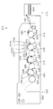
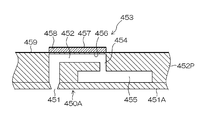
- a diagram showing a configuration example of an inkjet recording apparatus 29A is a plan perspective view showing an example of the structure of the head, and FIG. 29B is a partially enlarged view of part. Plane perspective view showing another structural example of the head Sectional view along line 31-31 in part (A) of FIG.
- the non-discharge correction technology changes the dot pattern at the image position corresponding to the nozzles in the vicinity of the non-discharge nozzles in the recording head, so that the non-discharge portions (streaky image defects) caused by the non-discharge nozzles are not discharged.
- This is a correction technique that compensates for dot recording by ejection from nozzles other than nozzles and reduces the visibility of image defects.
- the first method is a method of obtaining a corrected halftone image by performing correction processing on a multi-tone input image and performing halftone processing on the corrected image data.
- the second method is a method of obtaining a corrected halftone image by applying correction for correcting the dot arrangement to a halftone image obtained by halftone processing of an input image.
- FIG. 1 is a block diagram showing a flow of undischarge correction processing according to the first method.
- the discharge failure correction method 16 according to the first method uses discharge failure information 14 indicating the position of discharge failure nozzles for discharge image correction processing 16 for an input image 12 captured as original image data representing the image content to be printed. I do.
- the data format of the input image 12 is not particularly limited, here, for the sake of simplicity, it is assumed that the input image 12 is a gradation image having the same color type, number of colors, and resolution as the ink color used in the inkjet printing system. .
- the image data is 8 bits (256 bits) for each color of CMYK.
- Image data having (gradation).
- Undischarge information 14 is information indicating the position of the undischarge nozzle in the recording head of the ink jet printing system (“position information of undischarge nozzle”).
- position information of undischarge nozzle The position information of the undischargeable nozzle that cannot be used for image recording can be specified from the output result of the test pattern.
- the identified undischarge nozzle position information is stored as undischarge information 14 in an undischarge information storage unit such as a memory.
- the undischarge correction process 16 the image data at the image position in the vicinity of the undischarge nozzle is corrected, and an undischarge corrected image 18 which is corrected multi-tone image data is obtained.
- a halftone process 20 is performed on the discharge failure correction image 18 thus obtained, and a halftone image 22 which is image data representing a dot pattern is obtained.
- the halftone process 20 generally quantizes multi-tone image data of M values (M is an integer of 3 or more) and has N values (N is an integer of 2 or more and less than M) that can be recorded by the recording head. It is a process of converting to data.
- M is an integer of 3 or more
- N is an integer of 2 or more and less than M
- It is a process of converting to data.
- an image signal of 8 bits ⁇ (256 gradations) for each color of CMYK is converted into a signal (dot data) representing a multi-value dot arrangement of three or more values in pixel units.
- the halftone process 20 is performed with multiple gradations (for example, 4) “Discharge large droplet ink”, “Discharge medium droplet ink”, “Discharge small droplet ink”, “Do not discharge (no droplet)”
- a dither method, an error diffusion method, or the like is applied to such halftone processing. Large dots are formed on the recording medium by ejecting large drops, medium dots are formed by ejecting medium drops, and small dots are formed by ejecting small drops.
- the halftone image 22 generated through the halftone process 20 becomes dot data reflecting the gradation correction of the discharge failure correction process 16. That is, in the first method, undischarge correction is performed at the data stage of the continuous tone image before halftone processing, and the signal value (gradation value) corresponding to the image position near the undischarge nozzle is increased. A halftone image 22 corrected by the procedure of performing the halftone process 20 on the discharge failure correction image 18 is obtained.
- the process of performing the undischarge correction process 16 corresponds to the “undischarge correction process process”, and the process of performing the halftone process 20 corresponds to the “halftone process process”.
- the undischarge correction function is realized by combining the undischarge correction process 16 and the halftone process 20.
- FIG. 2 is a block diagram showing the flow of undischarge correction processing by the second method.
- the undischarge correction method according to the second method converts the input image 12 that is the original image data into a multi-value halftone image 34 by a halftone process 32, and then performs an undischarge operation on the halftone image 34.
- the discharge failure correction process 36 is performed using the information 14.
- the undischarge correction process 36 a correction process is performed in which the ink amount of dots corresponding to the adjacent nozzles of the undischarge nozzle is corrected.
- a discharge failure corrected halftone image 38 which is dot data after discharge failure correction is obtained.
- the second method performs the halftone process before the undischarge correction, and performs the undischarge correction on the halftone image after the halftone process, thereby performing the undischarge corrected halftone image 38. Have gained.
- the process of performing the halftone process 32 corresponds to the “halftone process process”, and the process of performing the undischarge correction process 36 corresponds to the “undischarge correction process process”.
- the discharge failure correction function is realized by the discharge failure correction process 36.
- FIG. 3 is a schematic diagram of the discharge failure correction image 18
- FIG. 4 is a schematic view of a halftone image 22 that is a halftone processing result of the discharge failure correction image 18.
- reference numeral 40 denotes a line-type recording head (line head) in the single-pass inkjet printing system.
- the recording head 40 includes a plurality of nozzles 42 for ejecting ink droplets.
- the vertical direction in FIG. 3 is the paper feeding direction, which is called “y direction” or “sub-scanning direction”.
- a nozzle row 44 in which a plurality of nozzles 42 are arranged in a line along the x direction is depicted.
- the nozzles are not necessarily arranged in a line.
- the number of nozzles, nozzle density, and nozzle arrangement in the recording head are not particularly limited, and there may be various forms.
- a one-dimensional nozzle array in which a large number of nozzles are arranged on a straight line (in a line) at a constant interval may be used.
- a so-called staggered arrangement may be employed in which each nozzle row is shifted in the nozzle row direction by a half pitch of the nozzle interval (inter-nozzle pitch). Further, in order to achieve higher recording resolution, a configuration in which a large number of nozzles are two-dimensionally arranged on the ink ejection surface (nozzle surface), such as a matrix arrangement in which three or more nozzle rows are arranged, can be employed. .
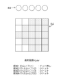
- the projected nozzle array in which the nozzles in the two-dimensional nozzle array are projected (orthographically projected) so as to be aligned along the medium width direction (corresponding to the main scanning direction)
- medium width direction corresponding to the main scanning direction
- equal intervals means substantially equal intervals as the droplet ejection points that can be recorded by the ink jet printing system.
- the concept of “equally spaced” also includes cases where the intervals are slightly different in consideration of manufacturing errors and movement of droplets on the medium due to landing interference.
- nozzle positions can be associated with the order of projection nozzles arranged along the main scanning direction.
- the term “nozzle position” refers to the position of the nozzle in this substantial nozzle row.
- the positional relationship in the substantial nozzle row is expressed. Since the nozzle position can be expressed as an x coordinate, the nozzle position can be associated with a position in the x direction (x coordinate).
- the total number of nozzles constituting the nozzle row 44 is appropriately designed according to the recording resolution and the drawable width.
- the eighth nozzle from the left among the plurality of nozzles 42 constituting the nozzle row 44 is an undischargeable nozzle 46 that cannot be discharged, and the other nozzles are normal nozzles that can be discharged.
- the x-direction pixel position corresponding to the position (nozzle number k) of the undischarge nozzle 46 cannot record a dot.
- the pixel line along the y direction at the corresponding position is a streak generating part in which a white streak (recording defective part) occurs on the print image.
- the first correction nozzle 47 (nozzle number k-1) and the second correction nozzle 48 (nozzle number k + 1) adjacent to the left and right with the undischarge nozzle 46 interposed therebetween.
- a pixel position (position indicated by arrows B1 and B2) corresponding to is used as an undischarge correction unit, and correction processing for increasing the gradation value of the pixel corresponding to the undischarge correction unit in the input image (continuous tone image) is performed. .
- the brightness display (display by shading) of each cell of the pixel grid shown in FIG. 3 reflects the magnitude of the gradation value, and the higher the gradation value, the darker the color is displayed.
- the gradation value of the pixel position corresponding to the first correction nozzle 47 and the second correction nozzle 48 of the discharge failure correction unit is changed to a value higher than the gradation value of the peripheral part (normal part) which is the non-correction part. ing.
- FIG. 4 is an example of a halftone process result obtained by performing a halftone process on the corrected image data shown in FIG. 3 (corresponding to the undischarge corrected image 18 in FIG. 1).
- the higher the gradation the larger the number of dots and the larger the dots appear. Therefore, as shown in FIG. 4, large dots are arranged in the discharge failure correction unit. As a result, the streak due to the undischarge nozzle 46 becomes difficult to see.
- the undischarge correction process by the first method has been described, but as a result, the dot pattern as shown in FIG. 4 can also be created by the undischarge correction process by the second method.
- FIGS. 3 and 4 an example is described in which correction is performed with two nozzles, the first correction nozzle 47 and the second correction nozzle 48 adjacent to both sides of the discharge failure nozzle 46, but the range of nozzles used for correction Is not limited to these two nozzles.
- FIG. 5 shows an example in which the dot pattern in the peripheral part (normal part) other than the correction part is similar to the dot pattern in the discharge failure correction part.
- FIG. 5A shows the dot pattern of the peripheral portion
- FIG. 5B shows the dot pattern of the discharge failure correction portion.
- the pattern is such that dots on (with dots) and dots off (without dots) are alternately repeated along the pixel rows arranged in the y direction.
- the average ink amount of the correction portion including the non-discharge portion (streak generation portion) corresponding to the non-discharge nozzle and the non-discharge correction portion corresponding to the two correction nozzles adjacent to the non-discharge nozzle, and the non-correction portion is equivalent to the average ink amount in the peripheral portion.
- Part (C) of FIG. 5 is a combination of the peripheral dot pattern shown in part (A) of FIG. 5 and the undischarge correction part dot pattern shown in part (B) of FIG.
- amendment process is shown.
- part of FIG. 5 shows the visual appearance of the printing result by the dot pattern of part (C) of FIG. Part (D) of FIG. 5 performs a filtering process that applies a visual transfer function (VTF) corresponding to the visual characteristics of the human eye to the dot pattern of part (C) of FIG. Obtainable.
- VTF visual transfer function
- FIG. 6 shows a case where the dot pattern in the peripheral portion is different from the dot pattern in the discharge failure correction portion.
- FIG. 6A shows the dot pattern of the peripheral portion
- FIG. 6B shows the dot pattern of the discharge failure correction portion.
- the (A) part of FIG. 6 is equivalent to the (A) part of FIG.
- the part (B) in FIG. 6 is different from the part (B) in FIG. 5 in the dot arrangement structure in the discharge failure correction unit. That is, the dot pattern of the discharge failure correction unit in the portion (B) of FIG. 6 is a pattern in which three dots continuously on in the y direction and three dots continuously off are repeated periodically.
- the dot pattern in the peripheral portion is a pattern in which dots on and dots are alternately repeated in units of one pixel in the y direction, and both patterns are greatly different.
- the average ink amount of the correction part including the non-discharge part (streak generation part) corresponding to the non-discharge nozzle and the non-discharge correction part corresponding to two correction nozzles adjacent to the non-discharge nozzle, and the non-correction part This is equivalent to the average ink amount in the peripheral portion.
- (C) part of FIG. 6 is a pattern combining the dot pattern of the peripheral part shown in part (A) of FIG. 6 and the dot pattern of the discharge failure correction part shown in part (B) of FIG. The dot arrangement of the halftone image obtained through the undischarge correction process is shown.
- part of FIG. 6 shows the visual appearance of the printing result by the dot pattern of part (C) of FIG.
- the part (D) in FIG. 6 can be obtained by performing filter processing corresponding to the visual characteristics on the dot pattern in the part (C) in FIG.
- the average ink amount for each pixel row arranged in the y direction before and after the correction as in the portion (D) in FIG. is seen as an unnatural texture.
- Such a phenomenon is remarkable when gradation expression is performed by a cluster structure pattern in which dots are arranged in an agglomerated manner, such as AM screen processing or cluster type halftone processing.
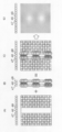
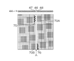
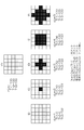
- FIG. 7 is an explanatory diagram showing an example of a recording failure due to an undischarge nozzle in an AM network.
- the upper left diagram in FIG. 7 represents a dot pattern of a normal image without discharge nozzles (an image without discharge failure).
- This cluster of dots (dot aggregation portion) is called a cluster.
- an example of an AM network in which clusters 70 that are clusters of dots of 4 ⁇ 4 pixels are regularly arranged is shown.
- the upper right diagram in FIG. 7 shows the visual appearance of the printed result using the dot pattern in the upper left diagram.
- the lower left diagram in FIG. 7 shows a dot pattern of an image without undischarge correction (uncorrected image) when the discharge failure nozzle 46 exists in the nozzle row 44 and discharge failure correction is not performed.
- the lower right diagram in FIG. 7 shows the visual appearance of the print result by the dot pattern in the lower left diagram.
- the leftmost 4 dots of the cluster indicated by reference numeral 70A cannot be recorded, and the rightmost 4 dots of the cluster indicated by reference 70B cannot be recorded. If the discharge failure correction is not performed for the discharge failure nozzle 46, the amount of ink is insufficient and a white streak is visually recognized as indicated by broken lines 72A and 72B in the lower right diagram of FIG. .
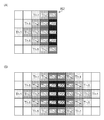
- FIG. 8 is an explanatory diagram of an example of occurrence of artifacts due to undischarge correction in the AM network.
- the left diagram in FIG. 8 is an example of a dot pattern in which discharge failure correction is performed on the discharge failure nozzle 46.
- this figure shows an example (comparative example) in the case where correction is made with characteristics different from the phase and cycle of the AM network without considering the relationship with the arrangement structure of the clusters in the peripheral portion at the time of discharge failure correction.
- Reference numerals 75 and 76 denote dots added by the discharge failure correction.
- the same number of dots as the number of dots that cannot be printed by the discharge nozzle 46 (eight) is added by the correction nozzles 47 and 48 on both sides of the discharge nozzle 46. That is, with respect to the pixel positions corresponding to the right and left correction nozzles 47 and 48 across the discharge failure nozzle 46, four dots 75 and 76 are added to the white background portion before correction (dot off portion between clusters), respectively. It has been made. The added dots 75 and 76 are arranged in a distributed manner so that the dots are distributed almost evenly in the correction portions at the pixel positions corresponding to the correction nozzles 47 and 48, and the ink amount is approximately preserved before and after the correction. As described above, the number of dots and the dot size are determined.
- the right figure in FIG. 8 shows the visual appearance of the print result by the dot pattern in the left figure in FIG.
- the visibility of the streaks is reduced compared to the lower right diagram of FIG. 7, but compared to the upper right diagram of FIG. 7, the portion where dots are not originally placed (the portion that was originally white) Since the additional dots 75 and 76 are placed on the printed matter, when the printed matter is observed close up (for example, when the printed matter is observed at a short distance of about 150 mm to 200 mm), the dot arrangement is visually recognized as a texture, and the correction portion cluster is darkened. appear.
- the user who observes at a short distance gives a sense of incongruity to the undischarge correction portion.
- the dot arrangement after the undischarge correction is visually recognized as a texture, which gives a sense of incongruity to the graininess.
- the non-discharge part is not limited to the dot pattern missing from the non-discharge nozzle 46 (recording defective part). It is also conceivable to perform non-discharge correction such that additional dots 75 and 76 are arranged in a coherent manner near the clusters 70A and 70B with the (streaks generation unit) interposed therebetween.
- Such a problem is not limited to the AM network, but also applies to the cluster type halftone in which dots are arranged in an agglomerated manner.
- the cluster type halftone is not as regularly arranged as the AM network, but has a pattern characteristic similar to that of the AM network in that two or more dots are continuously and aggregated in the nozzle arrangement direction.
- AM network and cluster type halftone originally have very few high-frequency components in the spatial frequency, if high-frequency components are generated in the non-correction part as a result of discharge failure correction, they are easily recognized as artifacts ([Problem 1-1] ).
- the dot pattern of the discharge failure correction part is similar to the dot pattern of the peripheral part An unnatural texture (artifact) can be suppressed by setting the pattern to be made.
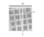
- FIG. 10 is a diagram showing an example of a halftone image obtained by applying undischarge correction according to the embodiment of the present invention. 10 solves [Problem 1] and [Problem 1-1] and [Problem 1-1-1] included in the white streak caused by the discharge failure nozzle 46 described in the lower part of FIG. This is an application of an undischarge correction method capable of
- the structure of the cluster 70 in the halftone image before correction is maintained, and dots are not arranged in the originally white background. 46, the dots 71A and 71B in the clusters 70A and 70B that are defective in recording are corrected to increase the dot size (increase the ink droplet amount).
- the right diagram in FIG. 10 is obtained by performing a filtering process considering the visual characteristics on the left diagram in FIG.
- the right figure in FIG. 10 looks very similar to the upper right figure in FIG. 7, and good correction is realized.
- [Problem 1] was approximated by considering the characteristics (local pattern characteristics) of the dot arrangement structure around the correction area in the halftone pattern when non-discharge correction was not applied (similar) It is preferable to determine the dot pattern of the discharge failure correction unit so as to be a pattern.
- an index of similarity for example, a simple difference sum between image data to be compared, a square sum of differences (SSD: Sum : of Squared Difference), a normalized cross-correlation (NCC), or the like may be used. It can. A specified value that defines an allowable range of similarity that does not affect the visibility is determined, and undischarge correction is performed to generate a dot pattern in which the similarity is equal to or less than the specified value before and after correction.
- SSD Sum : of Squared Difference
- NCC normalized cross-correlation
- the dot-off portion is 2 pixels in the non-correction portion, whereas the dot-off portion is 1 pixel in the correction portion. Due to the difference in the repetition period between the dot-on part and the dot-off part, the correction part appears to be connected.
- the cluster edge is undischarged, the pixel position in the cluster near the edge is corrected to be stronger, and when non-discharge occurs inside the cluster, the correction intensity is weaker than the correction intensity for the edge. It is preferable to correct by the above. Examples of specific means for solving the problem 2 will be described later.
- the first embodiment an example of undischarge correction in which tone correction is performed on an image before halftone processing will be described. That is, the first embodiment is an aspect of the discharge failure correction method according to the first method described in FIG.
- the dither method is a method of determining dot on / off by comparing a threshold value given to each pixel by a dither matrix and a gradation value of image data.
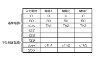
- FIG. 12 is a conceptual diagram of an area division lookup table (LUT).
- the first column (leftmost column) in FIG. 12 represents the input gradation, and here, a value of 8-bit gradation (gradation value 0 to 255) is used.
- a boundary approximately in the middle of the gradation area for example, “127” as a boundary, the discharge correction gradation is set above “127”, and the normal gradation is set below “127”. That is, the range of gradation values 0 to 127 is “normal gradation”, and the range of gradation values 128 to 255 is set to “undischarge correction unit gradation”.
- Three levels of threshold values are set for each gradation value.
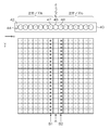
- FIG. 13 is an explanatory diagram of a region classification method using a dither matrix.
- a dither matrix 80 of 5 rows ⁇ 5 columns is shown, but this is the actual dither matrix size (number of elements) that is a part of the dither matrix actually used. Can design any size, such as 192x192, 400x500.
- a value in the range of 0 to 255 is defined for each cell (element) of the dither matrix 80.
- the magnitude of the value of the element is represented by brightness, and white represents 0, black represents 255, and gray represents a value in between.
- the position of each cell in the dither matrix 80 is expressed as (u, v) using the row number u and the column number v.
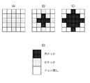
- the dither matrix 80 has a distribution such that the value gradually increases from the center cell (3, 3) toward the outer periphery. If the value of the element of the dither matrix 80 is x, for example, it can be divided into four types of regions (regions 1 to 4) using three types of threshold values (Th1 ⁇ Th2 ⁇ Th3). That is, the region 1 is a region that satisfies the condition x ⁇ Th1. As shown in the part (B) in FIG. 13, the region 1 has a center (3, 3) and four positions (3, 2), (3,4), (2, 3) on the top, bottom, left and right. , (4, 3).
- Area 2 is an area that satisfies the condition of Th1 ⁇ x ⁇ Th2. As shown in part (C) of FIG. 13, the region 2 is in contact with the outside of the region 1 (1,3), (2,2), (2,4), (3,1), (3 , 5), (4, 2), (4, 4), and (5, 3).
- Area 3 is an area that satisfies the condition of Th2 ⁇ x ⁇ Th3. As shown in the part (D) in FIG. 13, the region 3 touches the outside of the region 2 (1,2), (1,4), (2,1), (2,5), (4, 1) It is composed of 8 pixels including (4,5), (5,2) and (5,4).
- Region 4 is a region that satisfies the condition of Th3 ⁇ x.
- the region 4 includes (1,1), (1,5), (5,1), and (5,5) that are in contact with the outside of the region 3 as shown by the portion (E) in FIG. Consists of pixels.
- the shape of each region can be changed by changing the threshold values Th1, Th2, and Th3 for each gradation.
- the overall dot arrangement state (whether the dot is placed or not It is possible to change only the type of dot used (for example, the type of large dot, medium dot, and small dot) without changing the state.
- FIG. 14 is an explanatory diagram showing an example of an operation that can be performed by changing the dot type for each region.
- 14A shows a pattern when the regions 1 and 2 described in FIG. 13 are “small dots (small droplets)” and the regions 3 and 4 are “no dots (no droplets)”.
- 14B shows a pattern when the area 1 is “large dot (large drop)”, the area 2 is “small dot”, and the areas 3 and 4 are “no dot”.
- FIG. 14C shows a pattern when the areas 1 and 2 are “large dots” and the areas 3 and 4 are “no dots”.
- various dot patterns can be generated by combining the region dividing method using the dither matrix 80 and the method of changing the dot type for each region.
- the cluster shape can be manipulated for each gradation. Also, the dot type to be output can be determined for each region.
- the dots used in the cluster without changing the overall dot arrangement state ie, the cluster shape.
- the type of can be changed. That is, it is possible to change only the dot type in the cluster without changing the cluster structure (dot on position) by designing the halftone process (reference numeral 20 in FIG. 1).
- the input gradation includes “normal gradation” used for the normal part (non-correction part) and “undischarge correction gradation” used for the undischarge correction part.
- a correction gradation value (non-discharge correction value) when performing non-discharge correction for a pixel having a normal gradation value of nLev is previously optimized and determined for each nozzle. This is the discharge correction gradation cLev.
- discharge failure correction gradation Since the optimum value of the discharge failure correction value differs depending on the nozzle position, a test pattern that simulates the discharge failure nozzle position is output, and the discharge failure correction gradation optimized for each nozzle is determined in advance. deep.
- a method for obtaining the optimum discharge failure correction value (discharge failure correction gradation) for example, a method described in JP 2012-071474 A can be used.
- a correspondence relationship that the non-discharge correction gradation cLev is applied at the time of non-discharge correction to the normal gradation nLev is determined in advance.
- the gradation of the image data is corrected with reference to the correspondence relationship.
- a dot pattern is defined by halftone processing corresponding to the input gradation of the image data.
- the total dot generation amount here is approximately equal between nLev and cLev.
- FIG. A portion (A) in FIG. 15 represents a dot pattern in the normal gradation nLev.
- the dot pattern corresponding to the normal gradation nLev 52% of small dots are recorded in a 5 ⁇ 5 pixel area (small dots are arranged in 13 out of 25 pixels). Both medium dots and large dots are 0%.
- the total amount of dots generated here represents the ratio of the number of dots placed with respect to the number of pixels of the matrix size as a percentage, and represents the dot recording rate with respect to the number of pixels of the matrix size.
- FIG. 15B to FIG. 15F show examples of how to provide a non-discharge correction gradation dot pattern with respect to the normal gradation.
- the total amount of dots generated in the discharge failure correction gradation cLev is made to be close to 52% in total.
- the breakdown of the dot type ratio that achieves a recording rate of around 52% is not a problem. That is, regardless of the dot types of small dots, medium dots, and large dots, the number of dots need only be noted and it may be in the vicinity of 52%.
- area 1 (0 ⁇ x ⁇ Th1) is a large dot
- area 2 (Th1 ⁇ x ⁇ Th2) is a large dot
- area 3 (Th2 ⁇ x ⁇ Th3) is a small dot. If the dot type for each region is defined in such a manner that the region 4 (Th3 ⁇ x ⁇ 255) has no dots, the total number of the regions 4 (F) to (F) in FIG. It is possible to change the dot pattern to be generated without changing the dot amount (total dot generation amount).
- the undischarge correction gradation corresponding to the normal gradation nLev is defined in the gradation range from cLev1 to cLev2, and cLev1 to cLev2 In the gradation within the range, the total dot generation amount is set to be approximately equal.
- the difference in the total amount of dot generation is within 5%. If the difference in the total amount of dots generated is within 5%, it is considered that the change (difference) in the cluster shape does not substantially affect the visibility, and this level of difference is acceptable.
- Second Embodiment Next, a specific example for dealing with [Problem 2] will be described.
- the second embodiment an example of undischarge correction in which gradation correction is performed on an image before halftone processing will be described. That is, the second embodiment is an aspect of the discharge failure correction method according to the first method described in FIG.
- clusters are sequentially formed from the inside of the cluster in the nozzle array direction toward the cluster end as the tone shifts from low to high. In such a case, it is possible to increase the correction intensity at the cluster end by controlling the discharge failure correction gradation so that a larger dot appears at the cluster end.
- FIGS. 16 to 20 are explanatory diagrams of a method of changing the correction intensity of the correction unit by designing the dither matrix.
- 16A shows a part of a dither matrix used for cluster type halftone processing.
- the size of the element value in the dither matrix 82 is displayed in terms of brightness, and the condition of Th1 ⁇ Th2 ⁇ Th3 ⁇ 255 is satisfied.
- the horizontal direction of the dither matrix 82 is the “nozzle arrangement direction” (nozzle arrangement direction).
- the cluster gradually grows from the inside of the cluster in the nozzle arrangement direction toward the cluster end as the input gradation value changes from the low gradation to the high gradation (
- the dots are arranged so that the cluster of dots is expanded.
- a dither matrix is created in which the element values change stepwise from the inside of the cluster toward the end.
- Th1, Th2, Th3 and “255” are shown for simplicity of explanation.
- image gradation such as 8 bits or 10 bits. The values are distributed.
- part of FIG. 16 shows a part forming the left half of the cluster.
- the elements of the dither matrix constituting one cluster are configured such that the elements of the matrix in the part (A) of FIG. 16 appear symmetrically.
- the actual dither matrix is configured such that elements such as part (B) of FIG. 16 are further arranged periodically.
- FIG. 17 is an explanatory diagram when no discharge nozzle is present.
- the region 1 (0 ⁇ x ⁇ Th1) has no dots
- the region 2 (Th1 ⁇ x ⁇ Th2) has small dots
- the region 3 The dot generation method of each region is set so that small dots are generated in Th2 ⁇ x ⁇ Th3) and small dots are generated in region 4 (Th3 ⁇ x ⁇ 255).
- the halftone process is performed by applying the dither matrix 82 of FIG. 16
- a dot pattern in which small dots are aggregated to form a cluster as shown by reference numeral 84 in FIG. 17 is obtained.
- the dot pattern to be generated is made different depending on the position of the undischarge nozzle in the nozzle array 44 of 5 nozzles.
- FIG. 18 is an explanatory diagram of a method of changing the correction intensity of the correction unit depending on the position of the discharge failure part.
- the area 1 (0 ⁇ x ⁇ Th1) has no dots
- the area 2 (Th1 ⁇ x ⁇ Th2)
- the dot generation method of each area is set so that large dots, medium dots in area 3 (Th2 ⁇ x ⁇ Th3), and medium dots in area 4 (Th3 ⁇ x ⁇ 255) are generated.
- the size of the dot is displayed by brightness, and the darker the color, the larger the dot.
- the part (D) of FIG. 18 shows the correspondence between the dot type and the brightness display in the parts (A) to (C) of FIG. 17 and FIG.
- FIG. 18A shows a case where the second nozzle from the left in the nozzle row 44 is a discharge failure nozzle.
- a position corresponding to the discharge failure nozzle is a streak generation unit.
- Two nozzles adjacent to both sides serve as correction nozzles.
- pixels that were originally white (no dots) are left without dots.
- FIG. 18B shows a case where the third nozzle from the left in the nozzle row 44 is a discharge failure nozzle.
- a large dot is placed at “Th1” in (2, 2) and (2, 4), and a medium dot is placed at “Th2” in (2, 3).
- medium dots are placed in all the fourth pixel columns from the left.
- FIG. 18C shows a case where the fourth nozzle from the left in the nozzle row 44 is a discharge failure nozzle.
- large dots are placed at “Th1” in (3,1) and (3,5), and medium dots are placed in the remaining correction portions.
- a correction pattern corresponding to the discharge failure position can be developed. That is, a large dot is generated at the end of the cluster, and a medium dot is generated when going inside the cluster.
- the correction strength is automatically applied between the end and the inside without determining the position of whether the correction unit is the end or the inside of the cluster. Can be made to change.
- the second embodiment it is possible to change the correction strength between the end portion and the inside of the cluster, and the correction strength is automatically increased and the correction strength is decreased inside the cluster as it goes to the end portion of the cluster.
- Such an undischarge correction function can be realized.
- a correction dot conversion table corresponding to the distance from the cluster end in the nozzle arrangement direction is designed in advance, and for each of the correction unit pixels of the given halftone image, the cluster end After calculating the distance from, a process of replacing with a correction dot is performed with reference to the correction dot conversion table according to the type of each dot before correction.
- FIG. 19 represents a halftone image before correction. Similar to FIG. 17, a 5 ⁇ 5 pixel range is shown. It is assumed that the third nozzle from the left in the nozzle row 44 is an undischarge nozzle. In the halftone image 84 before correction, dots are also assigned to pixel positions (undischarge portions) corresponding to undischarge nozzles.
- the pixel distance from the cluster end is calculated in the lateral direction (nozzle arrangement direction).
- (B) in FIG. 19 represents the distance from the cluster edge in units of pixels (px).
- the pixel at the end (boundary) of the cluster has a distance “0”, and the distance from the end gradually increases as the distance from the end becomes 1 ⁇ 2 ⁇ 3.
- the distance is measured from the left to the right, but the distance can also be measured from the right to the left of the cluster. It is only necessary to calculate the distance from both the left and right directions and adopt a short distance.
- the distance from the cluster end is calculated in units of pixels, but the unit of distance is not limited to this, and any index value may be used as long as it is an index indicating distance.
- the distance can be expressed using an appropriate function.
- 19C is an example of the corrected halftone image 85 in which the correction for changing the dot type is performed according to the distance from the cluster end.
- the size of the dot is displayed in terms of brightness, and the darker the color, the larger the dot.
- the part (D) in FIG. 19 shows the correspondence between the dot type and the brightness display.
- FIG. 20 is an example of a correction dot conversion table.
- the horizontal axis indicates the dot type before correction, and the vertical axis indicates the dot type after correction.
- the correction dot conversion table actually defines the correspondence before and after the correction of four types of discrete values (dot types), but in FIG. Indicated by.
- the correction dot conversion table of FIG. 20 it is preferable to design the table so that the dots are not switched in a white background where no dots are originally placed.
- the distance from the cluster end of the discharge failure correction unit is obtained for the halftone image, and the dot size is changed with reference to the correction dot conversion table.
- the difference in the total amount of dots before and after correction is allowed to be about 5%
- the control of generating dots with a certain probability (with a generation ratio of 5% or less) with respect to “no dot” before correction is also possible. Is possible.
- the simplest method is to generate 42Y patterns in an exhaustive search, and select the optimal pattern that is most similar to the uncorrected pattern and eliminates streaks after considering visual characteristics. Perform optimization operations on.
- the search range can be narrowed down by restricting the discharge ink amount of the correction nozzle to be close to 1.5 times or by restricting the contour of the cluster to be close.
- FIG. 1 An example of a specific procedure is shown in FIG.
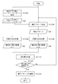
- FIG. 21 is a flowchart showing an example of a correction pattern optimization procedure.
- an image area around the discharge failure portion is extracted from the given halftone image, and a halftone pattern before correction (when there is no discharge failure) is acquired (step S102).
- a pattern of an image area an image area corresponding to the discharge failure correction section
- the process which extracts is performed.
- a correction pattern as a pattern candidate of the discharge failure correction unit is generated for the periphery of the discharge failure part corresponding to the pre-correction dischargeless halftone pattern 92 acquired in step S102 (step S104).
- the correction pattern 94 generated here is a candidate dot pattern arranged in the pixel row corresponding to the two correction nozzles adjacent to both sides of the discharge failure nozzle.
- the pixel row (non-discharge portion) corresponding to the non-discharge nozzle in the correction pattern 94 is “no dot”, and a pattern in which four-value dot types are appropriately assigned to the pixel row adjacent to the non-discharge portion.
- arithmetic processing for superimposing a visual filter corresponding to the visual characteristics is performed on each of the uncorrected undischarge-free halftone pattern 92 and the correction pattern 94 (steps S106 and S108).
- a Dooley-Shaw VTF Vehicle Transfer Function
- step S106 By performing the spatial frequency processing (step S106) on the uncorrected undischargeless halftone pattern 92, the “uncorrected appearance image corresponding to the appearance of the undischarged portion around the undischargeless halftone image before correction” is displayed.
- the data 96 of “im1” is obtained.
- step S108 by performing spatial frequency processing (step S108) on the correction pattern 94, data 98 of “correction portion appearance image im2” corresponding to the appearance of the correction portion is obtained.
- step S110 the similarity S between the appearance image im1 before correction and the appearance image im2 of the correction unit is evaluated.
- An example of a method for calculating the similarity S will be described later.
- step S110 The similarity S calculated in step S110 is compared with a predetermined threshold (specified value) (step S120). If the similarity S is larger than the threshold (if the similarity is lower than the similarity indicated by the threshold). ) Since the correction pattern 94 is not appropriate, the process returns to step S104, a new (other) correction pattern is generated, and the processes of steps S104 to S110 are repeated.
- a predetermined threshold specified value
- step S110 If the similarity S calculated in step S110 is equal to or less than a threshold value (if the similarity is high), the correction pattern 94 is allowed as an appropriate correction pattern, and this is adopted as the dot pattern of the correction unit ( Step S124), the process is terminated.
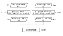
- FIG. 22 is a flowchart illustrating an example of a procedure for evaluating the similarity S.
- the data 96 of the appearance image im1 before correction is averaged in the nozzle row direction (x direction) to create a brightness profile in the paper feed direction (y direction) (step S111).
- the data 98 of the appearance image im2 of the correction unit is averaged in the nozzle row direction (x direction), and a profile in the paper feed direction (y direction) is created (step S112).
- the similarity S is calculated based on the pre-correction profile p1 data 101 created in step S111 and the correction unit profile p2 data 102 created in step S112 (step S114).
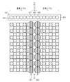
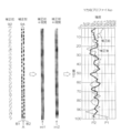
- FIG. 23 is an explanatory diagram schematically showing a generation process of the pre-correction profile p1 and the correction unit profile p2.
- the non-discharge non-discharge halftone pattern 92 is a dot pattern of an image portion (3 pixels in the x direction and image width in the y direction) corresponding to the 3 nozzles of the discharge failure nozzle and the two nozzles on both sides thereof.
- the horizontal direction in the figure is the x direction
- the vertical direction is the y direction.
- the y-direction pixel row (the portion of the pixel row indicated by symbol A) at the pixel position corresponding to the discharge failure nozzle becomes “no dot” due to the inability to record, and the pixel position corresponding to the correction nozzles on both sides thereof.
- This is a pattern in which dots are arranged in the y-direction pixel row (pixel row portions indicated by reference numerals B1 and B2).
- the difference in dot type is displayed in terms of brightness, with white indicating no dots, black indicating large dots, and gray indicating small dots or medium dots.
- a spatial frequency process for superimposing a visual filter is performed, thereby correcting the appearance of each pattern.
- a previous appearance image im1 and a correction portion appearance image im2 are obtained.
- the average image p1 before correction is averaged in the x direction (three pixel columns are averaged) to obtain a pre-correction profile p1 as the y-direction profile before correction.
- the correction unit profile p2 as the y direction profile of the correction unit is obtained by averaging the appearance image im2 of the correction unit in the x direction (average of three pixel columns).
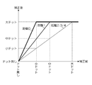
- the graph shown on the right side of FIG. 23 shows the relationship between the position in the y direction and the intensity of the image signal.
- the profile indicated by the thin line is the pre-correction profile p1
- the profile indicated by the thick line is the correction unit profile p2. .
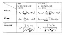
- FIG. 24 shows an example of a method for calculating the similarity S.
- the similarity S for example, simple difference sum, sum of squares of difference (SSD), normalized cross-correlation (NCC), or the like can be used.
- SSD sum of squares of difference
- NCC normalized cross-correlation
- S it may be defined in the real space of the image or may be defined in the Wiener spectrum.
- the calculation formulas for the respective similarities S are as shown in the table of FIG.
- the method for obtaining the optimum pattern in the correction unit is not limited to the above example. Even if it is not based on the full search method, the dot placement can be optimized using the Simulated Annealing method or the Void-and-Cluster method as a solution to the optimization problem. can do.
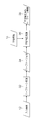
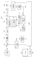
- FIG. 25 is a block diagram illustrating a configuration of the inkjet printing system according to the first embodiment and the second embodiment.
- the inkjet printing system 110 is a system that performs image recording by a single pass method, and includes an image data input unit 112, a gradation conversion unit 114, an undischarge correction processing unit 118, a halftone processing unit 120, a head driver 122, and a recording head. 124 is provided.
- the inkjet printing system 110 includes a medium conveyance unit 126 that conveys a recording medium (not shown in FIG. 25), an image reading unit 128 that reads an image recorded on the recording medium by the recording head 124, and an image reading unit.
- An image analysis unit 130 that analyzes the read image acquired from 128 is provided.
- the image analysis unit 130 includes a defective nozzle detection unit 132 and an undischarge correction parameter calculation unit 134.
- the defective nozzle detection unit 132 performs a process of detecting the position of the non-ejection nozzle based on the read image of the defective nozzle detection test chart. Further, the defective nozzle detection unit 132 calculates the landing position error of each nozzle based on the read image of the defective nozzle detection test chart, and forcibly causes discharge failure when the landing position error exceeds an allowable value. Designate an undischarge nozzle. Non-ejection nozzles and non-ejection nozzles detected by the defective nozzle detection unit 132 are treated as non-ejection nozzles.
- the undischarge nozzle position information (undischarge information) is stored in the undischarge information storage unit 140.
- the undischarge information storage unit 140 corresponds to an “undischarge information storage unit”, and the step of storing undischarge information in the undischarge information storage unit 140 corresponds to an “undischarge information storage step”.
- the discharge failure correction parameter calculation unit 134 performs a calculation process for determining an image gradation correction value (discharge failure correction parameter) of the adjacent nozzle with respect to the position of the discharge failure nozzle from the read image of the discharge failure correction parameter acquisition test chart.
- the discharge failure correction parameter calculation unit 134 generates discharge failure correction LUTs (corresponding to discharge failure correction parameters) that define correction values for discharge failure correction (discharge failure correction gradations) for each nozzle.
- the discharge failure correction parameter generated by the discharge failure correction parameter calculation unit 134 is stored in the discharge failure correction parameter storage unit 142.
- the inkjet printing system 110 includes a test chart generation unit 150 that generates data of various test charts including a test chart for detecting defective nozzles, a printing condition management unit 152 that manages printing conditions necessary for executing a print job, A control unit 162 that controls the entire system is provided, and a display unit 164 and an input device 166 are connected to the control unit 162.
- the display unit 164 and the input device 166 function as a user interface (UI).
- the input device 166 can employ various means such as a keyboard, a mouse, a touch panel, and a trackball, and may be an appropriate combination thereof.
- the form by which the display part 164 and the input device 166 are comprised integrally is also possible like the structure which has arrange
- the operator uses the input device 166 while viewing the contents displayed on the screen of the display unit 164 to input various information such as input of printing conditions, selection of image quality mode, input / editing of attached information, and information search. And the inkjet printing system 110 can be operated. Further, through the display on the display unit 164, the input content and other various information, the system status, and the like can be confirmed.
- Each unit can be realized by a combination of computer hardware and software used as a control device of the inkjet printing system 110.
- the image data input unit 112, the gradation conversion unit 114, the undischarge correction processing unit 118, the halftone processing unit 120, and the head driver 122 may be mounted as image processing functions on the ink jet recording apparatus (printer) side. It is possible to mount all or part of these image processing units (112 to 122) on the control device side.
- the recording head 124 is a line head having a nozzle row in which a plurality of nozzles are arranged over a length corresponding to the entire width of the drawing area in the medium width direction orthogonal to the conveyance direction of the recording medium (maximum width of the image forming area).
- the medium conveyance direction by the medium conveyance unit 126 is the sub-scanning direction (y direction), and the medium width direction orthogonal to the medium conveyance direction is the main scanning direction (x direction).
- FIG. 25 only one block is shown as the recording head 124 for the sake of simplicity.
- a plurality of recording heads respectively corresponding to a plurality of ink colors.
- CMKY four color inks are used, and a recording head for ejecting each color ink is provided for each color.
- the number of ink colors and combinations thereof are not limited to this example.
- a mode in which light color inks such as light cyan (LC) and light magenta (LM) are added, and a mode in which special color inks such as red and green are used are also possible.
- the ink jet recording head 124 has an ejection energy generating element (for example, a piezoelectric element or a heating element) that generates ejection energy necessary for ink ejection corresponding to each nozzle. I have.
- the recording head 124 ejects ink droplets on demand according to the drive signal and ejection control signal supplied from the head driver 122.
- the image data input unit 112 functions as a data acquisition unit for taking in image data (input image 12) representing image contents to be printed (output) by the inkjet printing system 110.
- the image data input unit 112 can be configured by a data input terminal that takes in image data from an external or other signal processing unit in the apparatus.
- the image data input unit 112 may employ a wired or wireless communication interface unit, or may employ a media interface unit that reads and writes an external storage medium (removable disk) such as a memory card. Alternatively, an appropriate combination of these aspects may be used.
- the image data format of the image to be printed can be various.
- a pre-processing unit (not shown) is used in the preceding stage of the image data input unit 112.
- the image data is input from the image data input unit 112 after being converted into image data of ink color and resolution used in the inkjet printing system 110 by performing processing such as color conversion and resolution change.
- RGB image data represented by red (R), green (G), and blue (B) color signals
- a RIP Raster Image Processor
- An apparatus or the like performs RGB ⁇ CMYK color conversion processing or resolution conversion processing, converts the RGB image data into CMYK image data suitable for the inkjet printing system 110, and then inputs the converted image data to the image data input unit 112.
- the gradation conversion unit 114 converts the image data so that the color development characteristics defined by the inkjet printing system 110 are obtained.
- the gradation conversion unit 114 converts the input CMYK signal (pre-density conversion CMYK signal) into a density-converted CMYK signal in accordance with the gradation conversion LUT specified by the printing condition management unit 152.
- the input CMYK signal (CMYK signal before density conversion) may be converted into a C signal after density conversion, an M signal after density conversion, a Y signal after density conversion, and a K signal after density conversion.
- the notation “LUT” in this specification represents a lookup table.
- the gradation conversion LUT is a table describing the relationship (conversion relationship) of the output signal value to the input signal value.
- the gradation conversion LUT is defined for each type of recording medium used for printing.
- a plurality of gradation conversion LUTs are prepared according to the paper type, and an appropriate LUT is referred to according to the paper to be used.
- Such a gradation conversion LUT is prepared for each ink color.
- a gradation conversion LUT is provided for each color of CMYK.
- the input image 12 fetched from the image data input unit 112 is subjected to gradation conversion processing so that a desired gradation is obtained by the gradation conversion unit 114.
- the gradation converting unit 114 has a density unevenness correction processing function for correcting image data in accordance with the recording characteristics depending on the position (x-direction position) of each nozzle of the recording head 124. That is, the gradation converting unit 114 performs image signal correction for suppressing density unevenness of the print image on the recording medium caused by variations in the ejection characteristics of the nozzles in the recording head 124.
- a density unevenness correction LUT which is a one-dimensional lookup table for correcting density unevenness describing the conversion relationship between the input signal value and the output signal value, is prepared. Signal values are converted using the LUT.
- Undischarge correction processing section The discharge failure correction processing unit 118 corrects the image data using the discharge failure information stored in the discharge failure information storage unit 140 and the discharge failure correction parameter stored in the discharge failure correction parameter storage unit 142. Perform correction processing.
- the halftone processing unit 120 is dot data of N values (N is 3 or more) that can output multi-tone image data by the recording head 124 by a quantization method such as a dither method (so-called digital halftoning processing method). Process to convert to.
- the N-value image data generated by the halftone processing unit 120 is converted in accordance with the nozzle arrangement and output to the head driver 122.
- a drive signal (marking signal) is supplied to the recording head 124 via the head driver 122, and the ink ejection operation of the recording head 124 is controlled.
- the medium transport unit 126 is a means for transporting the recording medium.
- the recording medium is conveyed at a constant speed in the sub-scanning direction (y direction) orthogonal to the longitudinal direction (x direction) of the recording head 124.
- the medium conveyance unit 126 can employ various methods such as a drum conveyance method, a belt conveyance method, and a nip conveyance method.
- the detailed structure of the medium transport unit 126 is not shown, it includes a paper feed roller, a transport motor, a motor drive circuit, and the like.
- a sensor for example, an encoder for detecting the position of the recording medium.
- the medium transport unit 126 corresponds to a relative moving unit that moves the recording medium relative to the recording head 124.
- the image reading unit 128 reads an image recorded on the recording medium by the recording head 124 and converts it into electronic image data (read image data).
- a CCD line sensor can be used as the image reading unit 128.
- the image reading unit 128 of this example is an inline sensor installed in the middle of the medium conveyance path, and reads an image recorded by the recording head 124 during conveyance before paper discharge.
- the image reading unit 128 can read the output results of a density measurement test chart and other test charts described later. Further, the image reading unit 128 can read a print image recorded based on image data to be printed specified in a print job.
- the test chart generation unit 150 has a function of generating data of a defective nozzle detection test chart for detecting defective nozzles and a non-discharge correction parameter acquisition test chart for calculating non-discharge correction parameters.
- the test chart generation unit 150 can generate various test chart data such as density measurement test chart data for obtaining density measurement data necessary for calculating density unevenness correction parameters.
- the test chart generation unit 150 supplies the data of the corresponding test chart to the image data input unit 112 according to the instruction of the control unit 162.
- the defective nozzle detection test chart for example, a so-called “1 on n off” type test chart can be used.
- the “1 on n off” type test chart shows the nozzle numbers in order from the end in the main scanning direction with respect to the arrangement of nozzles constituting one nozzle line in the x direction in one line head.
- the droplet ejection timing is changed for each nozzle number group of AN + B (where N is an integer of 0 or more), and a line group is formed by continuous droplet ejection from each nozzle.
- the line patterns of adjacent nozzles adjacent to each other do not overlap each other, and independent line patterns (for each nozzle) are formed for each nozzle.
- the presence / absence of discharge from each nozzle can be ascertained from the output result of the defective nozzle detection test chart.
- the landing position of each nozzle it is possible to determine that a nozzle having a large landing position error exceeding an allowable value is a discharge bent nozzle.
- a test chart for detecting defective nozzles is recorded in the margin of the recording medium one by one during printing, and this is read by the image reading unit 128 to detect the occurrence of defective nozzles at an early stage, thereby preventing discharge. Undischarge correction processing by processing is applied.
- the discharge chart for acquiring discharge failure correction parameters is a density pattern in which discharge failure correction parameters (correction coefficients) are applied to nozzle positions on both sides adjacent to a nozzle that simulates the presence of discharge failure nozzles (intentionally discharge failure). Contains patches.
- the optimum discharge failure correction parameter can be specified from the drawing result with different discharge failure correction parameter values.
- An appropriate correction value (correction coefficient) can be determined for each nozzle by creating a patch in which the position of the nozzle that simulates non-ejection is changed.
- the print condition management unit 152 manages print job information in which image data to be printed is associated with print condition information.
- the user can input print condition setting information when inputting image data to be printed or after inputting image data.
- the print condition management unit 152 generates print job information in which print condition setting information is associated with image data to be printed, and stores and manages the information for each print job.
- For each print job an output image data name, a recording medium type name (paper type), a medium size, and various parameter information used for image processing are stored in association with each other.
- the print condition management unit 152 sets various parameters and data designated by the print job related to the selection in the corresponding processing unit.
- the undischarge correction function described in the first embodiment and the second embodiment can be realized by the inkjet printing system 110 illustrated in FIG.
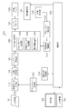
- FIG. 26 is a block diagram illustrating a configuration of an inkjet printing system according to the third embodiment.
- elements that are the same as or similar to the structure shown in FIG. 25 are given the same reference numerals, and descriptions thereof are omitted.
- the inkjet printing system 170 shown in FIG. 26 includes an undischarge correction processing unit 172 for realizing the undischarge correction function described with reference to FIGS. 16 to 18 and correction dot conversion in which a correction dot conversion table is stored.
- the undischarge correction processing unit 172 includes a distance calculation unit 173 that calculates the distance from the cluster end, and a dot replacement unit that performs a dot change process with reference to the correction dot conversion table according to the distance from the cluster end. 174.
- the halftone processing unit 120 in the ink jet printing system 170 may be of any method as long as it generates a halftone image that expresses gradations using AM network or cluster type halftone.
- the discharge failure correction function described in the third embodiment can be realized by the inkjet printing system 170 shown in FIG.
- FIG. 27 is a block diagram illustrating a configuration of an inkjet printing system according to the fourth embodiment.
- elements that are the same as or similar to those shown in FIG. 25 are given the same reference numerals, and descriptions thereof are omitted.
- the inkjet printing system 180 shown in FIG. 27 includes an undischarge correction processing unit 182 for realizing the undischarge correction function described with reference to FIGS.
- the undischarge correction processing unit 182 includes a correction pattern generation unit 183, a visual filter processing unit 184, and a similarity calculation unit 185.
- the correction pattern generation unit 183 performs the correction pattern generation process described in step S104 of FIG.
- the visual filter processing unit 184 performs the spatial frequency processing described in steps S106 and S108 in FIG.
- the similarity calculation unit 185 performs the similarity S calculation process described with reference to FIG.
- a combination of the correction pattern generation unit 183, the visual filter processing unit 184, and the similarity calculation unit 185 corresponds to “a calculation unit that optimizes the pattern of the discharge failure correction unit”.
- the halftone processing unit 120 in the ink jet printing system 180 of FIG. 27 may be of any method as long as it generates a halftone image that expresses gradation by AM network or cluster type halftone.
- the discharge failure correction in consideration of the halftone dot arrangement structure is performed so that the discharge failure correction unit pattern is similar to the peripheral portion, and the above-described artifacts are suppressed. can do.
- an appropriate discharge failure correction intensity can be set according to the distance from the cluster end.
- a program for causing a computer to function is a CD-ROM, a magnetic disk, or other computer-readable medium (tangible object).
- the program can be provided through the information storage medium. Instead of providing the program by storing the program in such an information storage medium, it is also possible to provide the program signal as a download service using a communication network such as the Internet.
- the computer stores a non-discharge information (non-discharge information storage function), a halftone processing function (halftone processing function), and an image defect in a defective recording area due to a defective nozzle. And a function of performing image correction processing (undischarge correction processing function) that reduces the visibility of the image can be realized, and the undischarge correction described in the above embodiment can be performed.
- a part or all of a program for realizing print control including the image processing function for performing the non-discharge correction function and the halftone process for realizing the non-discharge correction function described in the present embodiment is controlled by a host computer or the like. It is also possible to apply to an aspect incorporated in the apparatus or an operation program of a central processing unit (CPU) on the printer (inkjet recording apparatus) side as an image output apparatus.
- CPU central processing unit
- FIG. 28 is a diagram illustrating a configuration example of the ink jet recording apparatus 300.
- the ink jet recording apparatus 300 includes a paper feed unit 312, a treatment liquid application unit 314, a drawing unit 316, a drying unit 318, a fixing unit 320, and a paper discharge unit 322.
- a recording medium 324 that is a sheet is stacked on the paper feed unit 312.
- the recording media 324 are fed one by one from the paper feed tray 350 of the paper feed unit 312 to the processing liquid application unit 314.
- a sheet cut paper
- a configuration in which continuous paper (roll paper) is cut into a necessary size and fed is also possible.
- the processing liquid application unit 314 is a mechanism that applies the processing liquid to the recording surface of the recording medium 324.
- the treatment liquid contains a color material aggregating agent that agglomerates the color material (pigment in this example) in the ink applied by the drawing unit 316. When the treatment liquid comes into contact with the ink, the ink becomes a color material. And the solvent are promoted.
- the processing liquid application unit 314 includes a paper feed cylinder 352, a processing liquid drum 354, and a processing liquid coating device 356.
- the processing liquid drum 354 includes a claw-shaped holding means (gripper) 355 on the outer peripheral surface thereof, and the recording medium 324 is sandwiched between the claw of the holding means 355 and the peripheral surface of the processing liquid drum 354, thereby The tip can be held.
- the treatment liquid coating apparatus 356 can apply various methods such as a spray method and an ink jet method in addition to a roller coating method.
- the recording medium 324 to which the processing liquid is applied is transferred from the processing liquid drum 354 to the drawing drum 370 of the drawing unit 316 via the intermediate transport unit 326.
- the drawing unit 316 includes a drawing drum 370, a sheet pressing roller 374, and ink jet heads 372M, 372K, 372C, 372Y.
- the drawing drum 370 includes claw-shaped holding means (grippers) 371 on the outer peripheral surface thereof, like the processing liquid drum 354. Suction holes are provided on the outer peripheral surface of the drawing drum 370, and the recording medium 324 is sucked and held on the outer peripheral surface of the drum by negative pressure suction.
- a paper conveyance system including the drawing drum 370 corresponds to the medium conveyance unit 126 (see FIGS. 25 to 27).
- Each of the inkjet heads 372M, 372K, 372C, and 372Y is a full-line inkjet recording head having a length corresponding to the maximum width of the image forming area on the recording medium 324, and an image forming surface is formed on the ink ejection surface. A nozzle row in which a plurality of nozzles for ink ejection are arranged over the entire width of the region is formed.
- Each inkjet head 372M, 372K, 372C, 372Y is installed so as to extend in a direction orthogonal to the conveyance direction of the recording medium 324 (the rotation direction of the drawing drum 370).
- the recording medium 324 is transported at a constant speed by the drawing drum 370, and the operation of relatively moving the recording medium 324 and each of the inkjet heads 372M, 372K, 372C, 372Y in this transport direction is performed only once (that is, 1). An image can be recorded in the image forming area of the recording medium 324 in a single sub-scan).
- the ink jet recording apparatus 300 using four colors of CMYK inks is illustrated, but the combination of ink colors and the number of colors is not limited to this embodiment, and the arrangement order of each color head is not particularly limited.
- the recording medium 324 on which an image is formed by the drawing unit 316 is transferred from the drawing drum 370 to the drying drum 376 of the drying unit 318 via the intermediate conveyance unit 328.
- the drying unit 318 is a mechanism for drying moisture contained in the solvent separated by the color material aggregation action, and includes a drying drum 376 and a solvent drying device 378. Similar to the treatment liquid drum 354, the drying drum 376 includes a claw-shaped holding means (gripper) 377 on its outer peripheral surface.
- the solvent drying device 378 includes a plurality of halogen heaters 380 and a hot air jet nozzle 382.
- the recording medium 324 that has been dried by the drying unit 318 is transferred from the drying drum 376 to the fixing drum 384 of the fixing unit 320 via the intermediate conveyance unit 330.
- the fixing unit 320 includes a fixing drum 384, a halogen heater 386, a fixing roller 388, and an in-line sensor 390.
- the fixing drum 384 includes claw-shaped holding means (grippers) 385 on the outer peripheral surface thereof, like the processing liquid drum 354.
- the in-line sensor 390 reads an image (including a density measurement test chart, a defective nozzle detection test chart, an undischarge correction parameter acquisition test chart, etc.) formed on the recording medium 324, and the image density, image defect, and the like. And a CCD line sensor or the like is applied.
- the inline sensor 390 corresponds to the image reading unit 128 described with reference to FIG.
- the paper discharge unit 322 includes a discharge tray 392, and a transfer drum 394, a conveyance belt 396, and a stretching roller 398 are provided between the discharge tray 392 and the fixing drum 384 of the fixing unit 320 so as to be in contact therewith. Is provided.
- the recording medium 324 is sent to the transport belt 396 by the transfer drum 394 and discharged to the discharge tray 392. Although the details of the paper transport mechanism by the transport belt 396 are not shown, the recording medium 324 after printing is held at the front end of the paper by a gripper (not shown) gripped between the endless transport belts 396, and the transport belt 396. Is carried above the discharge tray 392.
- the ink jet recording apparatus 300 of the present example has an ink storage / loading unit that supplies ink to the respective ink jet heads 372M, 372K, 372C, and 372Y, and a treatment liquid applying unit 314. And a head maintenance unit for cleaning each inkjet head 372M, 372K, 372C, 372Y (nozzle surface wiping, purging, nozzle suction, etc.) and a recording medium 324 on the paper transport path.
- a position detection sensor for detecting the position, a temperature sensor for detecting the temperature of each part of the apparatus, and the like are provided.
- FIG. 29A is a perspective plan view showing an example of the structure of the recording head 450
- FIG. 29B is an enlarged view of a part thereof.
- 30 is a perspective plan view showing another example of the structure of the recording head 450
- FIG. 31 is a three-dimensional view of one-channel droplet discharge elements (ink chamber units corresponding to one nozzle 451) serving as recording element units.
- FIG. 30 is a sectional view showing a configuration (a sectional view taken along line 31-31 in FIG. 29).
- the recording head 450 of this example includes a plurality of ink chamber units (droplets) each including a nozzle 451 that is an ink discharge port, a pressure chamber 452 corresponding to each nozzle 451, and the like.
- discharge elements 453 has a two-dimensionally arranged structure, so that a substantial nozzle interval (projection) that is projected (orthographically projected) along the head longitudinal direction (direction orthogonal to the paper feed direction). Nozzle pitch) is increased.
- a nozzle row having a length corresponding to the entire width Wm of the drawing area of the recording medium 324 is configured in a direction (arrow M direction; main scanning direction) substantially orthogonal to the feeding direction (arrow S direction; sub-scanning direction) of the recording medium 324.
- the form to do is not limited to this example.
- short head modules 460A in which a plurality of nozzles 451 are two-dimensionally arranged are arranged in a staggered manner.
- a mode of configuring a line head having a nozzle row having a length corresponding to the entire width of the recording medium 324 by connecting, or a mode of connecting the head modules 460B in a row as shown in FIG. 30 (B). is there.
- the pressure chamber 452 provided corresponding to each nozzle 451 has a substantially square planar shape (see part (A) and part (B) in FIG. 29), and one of the corners on the diagonal line. Are provided with an outlet to the nozzle 451, and an inlet (supply port) 454 for supply ink is provided on the other side.
- the shape of the pressure chamber 452 is not limited to this example, and the planar shape may have various forms such as a quadrangle (rhombus, rectangle, etc.), a pentagon, a hexagon, other polygons, a circle, an ellipse, and the like.
- the recording head 450 has a structure in which a nozzle plate 451A in which nozzles 451 are formed and a flow path plate 452P in which flow paths such as a pressure chamber 452 and a common flow path 455 are formed are laminated and joined. Become.
- the flow path plate 452P constitutes a side wall portion of the pressure chamber 452 and a flow path forming a supply port 454 as a throttle portion (most narrowed portion) of an individual supply path that guides ink from the common flow channel 455 to the pressure chamber 452. It is a forming member.
- the flow path plate 452P has a structure in which one or a plurality of substrates are stacked, although it is illustrated in FIG. 31 in a simplified manner.
- the nozzle plate 451A and the flow path plate 452P can be processed into a required shape by a semiconductor manufacturing process using silicon as a material.
- the common channel 455 communicates with an ink tank (not shown) as an ink supply source, and the ink supplied from the ink tank is supplied to each pressure chamber 452 through the common channel 455.
- a piezoelectric actuator 458 provided with individual electrodes 457 is joined to a diaphragm 456 constituting a part of the pressure chamber 452 (the top surface in FIG. 31).
- the diaphragm 456 of this example functions as a common electrode 459 corresponding to the lower electrode of the piezoelectric actuator 458. It is also possible to form the diaphragm with a non-conductive material such as silicon or resin. In this case, a common electrode layer made of a conductive material such as metal is formed on the surface of the diaphragm member.
- the piezoelectric actuator 458 By applying a driving voltage to the individual electrode 457, the piezoelectric actuator 458 is deformed and the volume of the pressure chamber 452 is changed, and ink is ejected from the nozzle 451 due to the pressure change accompanying this.
- the ink chamber unit 453 having such a structure is constant along the row direction along the main scanning direction and the oblique column direction having a constant angle ⁇ not orthogonal to the main scanning direction.
- the high-density nozzle head of this example is realized by arranging a large number in a grid pattern with the arrangement pattern.
- the arrangement form of the nozzles 451 is not limited to the illustrated example, and various nozzle arrangement structures can be applied.
- the means for generating discharge pressure (discharge energy) for discharging droplets from each nozzle in the recording head is not limited to a piezoelectric actuator (piezoelectric element).
- various pressure generating elements such as heaters (heating elements) in electrostatic actuators, thermal methods (methods that eject ink using the pressure of film boiling by heating of the heaters), and various other actuators
- a discharge energy generating element can be applied.
- Corresponding energy generating elements are provided in the flow path structure according to the ejection method of the head.
- the “recording medium” includes media called by various terms such as a printing medium, a recording medium, an image forming medium, an image receiving medium, and an ejection medium.
- the material, shape, etc. of the recording medium are not particularly limited, and a print on which a resin sheet such as continuous paper, cut paper, seal paper, OHP sheet, film, cloth, nonwoven fabric, wiring pattern, or the like is formed.
- a resin sheet such as continuous paper, cut paper, seal paper, OHP sheet, film, cloth, nonwoven fabric, wiring pattern, or the like is formed.
- Various sheet bodies can be used regardless of the substrate, rubber sheet, and other materials and shapes.
Landscapes
- Engineering & Computer Science (AREA)
- Multimedia (AREA)
- Signal Processing (AREA)
- Quality & Reliability (AREA)
- Physics & Mathematics (AREA)
- Discrete Mathematics (AREA)
- General Physics & Mathematics (AREA)
- Ink Jet (AREA)
- Particle Formation And Scattering Control In Inkjet Printers (AREA)
- Color, Gradation (AREA)
Abstract
本発明は、不吐補正によるアーティファクトを抑制し、良好な不吐補正を実現することができるインクジェット印刷システム及びその不吐補正方法を提供する。本発明の一態様に係るシングルパス方式で画像記録を行うインクジェット印刷システム(110)は、不吐ノズルの位置情報を記憶しておく不吐情報記憶部(140)と、入力画像から3値以上の多値のハーフトーン画像を生成するハーフトーン処理部(120)と、入力画像に対して、不吐ノズルの位置情報に基づき、不吐ノズルによる記録不良部の画像欠陥の視認性を低減させる画像の補正処理を行う不吐補正処理部(118)と、を備え、ハーフトーン処理部(120)によって得られるハーフトーン画像のドット配置構造と不吐ノズルの位置情報とに基づき、記録不良部に近接する不吐補正部のドットパターンを生成する不吐補正を行う。
Description
本発明はインクジェット印刷システム及びその不吐補正方法並びにプログラムに係り、特に、シングルパス方式で画像記録を行うインクジェット印刷システムにおける不吐ノズルによる記録不良を補正する画像補正技術に関する。
インクジェット印刷システムは、複数のノズルを有する記録ヘッドを備え、印刷対象の画像データに基づいて各ノズルからのインク吐出動作を制御することにより印刷用紙などの記録媒体上に画像を形成する。記録ヘッドは、ノズルの目詰まりや吐出エネルギー発生素子の故障などにより、吐出不能な不吐ノズルが発生することがある。また、吐出可能なノズルであっても着弾位置誤差が許容値を超えて大きくなる吐出曲がりが発生する不良ノズルについて、記録に使用しないよう強制的に不吐化処理し、不吐ノズルとして扱う場合がある。
ライン型の記録ヘッド(ラインヘッド)を用いたシングルパス方式の印刷システムの場合、不吐ノズルに対応する画像位置は、ドットの記録が不能になるため、印刷画像において用紙送り方向に沿って白いスジ状の画像欠陥となる。このような不吐ノズルに起因する白スジの画像欠陥を改善するための補正技術として、「不吐補正」の技術が提案されている(特許文献1、2)。不吐補正という用語は「不吐出補正」と同義であり、本明細書では「不吐補正」と表記する。
不吐補正は、不吐ノズルに近接する他の吐出可能ノズル(非不吐ノズル)から打滴するドットを変更することにより実現される。不吐補正の際には、インク量が補正前後でおよそ近いものとなることが補正の適切な条件とされる。例えば、1つのノズルが不吐となり、その不吐ノズルの両脇の2ノズルで補正を行う場合には、本来、不吐ノズルとその両脇の2ノズルを合わせた3ノズルから吐出すべき予定のインク量を、両脇の2ノズルで吐出することになる。したがって、不吐ノズルの両脇の各補正ノズルから吐出されるインク量を通常部(非補正部)のインク量の1.5倍程度にすると、通常部と補正部の濃度差が小さくなり、印刷物において不吐補正の補正部分が目立たなくなる。なお、実際には、ノズルごとに吐出特性に違いがあるため、インク量を厳密に1.5倍とせずにある程度、補正値に幅を持たせることになる。
しかし、不吐補正における補正ノズルのインク量が適切に調整された場合であっても、通常部と不吐補正部のドットパターンが異なると、スジをきれいに消すことができない場合がある。例えば、印刷業において、印刷物におけるスジ状の画像欠陥は、観察者が印刷物に近づいて注意深く目視観察して評価される場合が多い。そのため、マクロに見て通常部と補正部との濃度が同等であったとしても、両者のドット配置の構造が異なり、ミクロなパターン形態が異なっていると、空間周波数の違いから、粒状の違いが観察され、不自然なテクスチャ(アーティファクト)として問題となる(詳細は図6を用いて後述する)。
この現象は、特に、AM(Amplitude Modulation)網や、ドットを凝集的に配置するクラスタ型のハーフトーンによって階調表現を行う場合に顕著である(詳細は図8を用いて後述する)。
また、AM網やクラスタ型ハーフトーンの場合には、不吐補正部がドット凝集部(クラスタ)の内部であるか、端部であるかによって不吐補正の効き方が異なるという問題がある。
すなわち、クラスタの内部に不吐補正部がある場合には、不吐部に近接する両側のドットからのインクが補正部に流れ込んでくる。その一方、不吐補正部がクラスタの端部である場合には、不吐部の片側にドットが無く、上記のような両側からのインクの流れ込みが生じない。このような現象の相違を考慮せずに、一律に補正を行うと、不吐部のスジが十分に補正されないことがある。従来の不吐補正技術では、クラスタに対する不吐補正部の位置の違いによる補正効果の相違を考慮していなかった。
上述の課題を整理すると、次のとおりである。
[課題1]不吐補正部のパターンが通常部の空間周波数特性と異なる場合に発生するアーティファクトを抑制する。
[課題1-1]課題1におけるさらに具体的な事項として、特に、AM網やクラスタ型ハーフトーンの場合には、元々、空間周波数における高周波成分が非常に少ないため、非補正部に高周波成分が生じると、視認されやすい。したがって、このようなアーティファクトを抑制する。
[課題1-1-1]また、課題1-1におけるさらに具体的な事項として、上記の高周波成分の違いは、元々白地だった箇所にドットを配置すると発生しやすい。
[課題2]AM網やクラスタ型ハーフトーンでは、ドットの凝集部であるクラスタの内部と端部とで最適な不吐補正の強度が異なるため、一律に補正を行うと、スジが充分に補正されない。
本発明はこのような事情に鑑みてなされたものであり、上記の課題の少なくとも1つを解決し、良好な不吐補正を実現できるインクジェット印刷システム及びその不吐補正方法並びにプログラムを提供することを目的とする。
前記目的を達成するために、次の発明態様を提供する。
(第1態様):第1態様に係るインクジェット印刷システムは、シングルパス方式で画像記録を行うインクジェット印刷システムであって、複数のノズルを有する記録ヘッドと、複数のノズルのうち画像記録に使用不能な不吐ノズルの位置情報を記憶しておく不吐情報記憶部と、入力画像を量子化して3値以上の多値のドットパターンを示すハーフトーン画像を生成するハーフトーン処理部と、入力画像に対して、又はハーフトーン画像に対して、不吐ノズルの位置情報に基づき、不吐ノズルによる記録不良部の画像欠陥の視認性を低減させる画像の補正処理を行う不吐補正処理部と、を備え、ハーフトーン処理部によって得られるハーフトーン画像のドット配置構造と不吐ノズルの位置情報とに基づき、記録不良部に近接する不吐補正部のドットパターンを生成する不吐補正を行う不吐補正機能を有するインクジェット印刷システムである。
この態様によれば、ハーフトーン処理によるドットの配置構造を考慮した不吐補正を行うことにより、補正部分でのアーティファクトを抑制したり、適切な補正強度を設定したりすることが可能になる。
インクジェット印刷システムにおける不吐補正機能は、不吐補正処理部による補正処理とハーフトーン処理部によるハーフトーン処理との組み合わせによって実現する態様と、不吐補正処理部による補正処理によって実現する態様とがあり得る。
(第2態様):第1態様に記載のインクジェット印刷システムにおいて、ハーフトーン処理部は、AM(Amplitude Modulation)網、又は、記録ヘッドのノズル配列方向に2つ以上のドットが凝集的に配置されるクラスタ型のハーフトーンによって階調表現を行うハーフトーン画像を生成する構成とすることができる。
(第3態様):第1態様又は第2態様に記載のインクジェット印刷システムにおいて、不吐補正機能によって生成される不吐補正部の補正後のドットパターンが、非補正部のドットパターンと類似したパターンである構成とすることができる。
不吐補正部の補正後のドットパターンを、その近傍の非補正部のドットパターンと類似性のあるパターンにすることで、補正部分のアーティファクトを抑制することができる。
(第4態様):第1態様から第3態様のいずれか1項に記載のインクジェット印刷システムにおいて、不吐補正機能による補正の前後で、画像の類似度が規定値以下である構成とすることができる。
(第5態様):第4態様に記載のインクジェット印刷システムにおいて、類似度は、単純差分和である構成とすることができる。
(第6態様):第4態様に記載のインクジェット印刷システムにおいて、類似度は、差の2乗和である構成とすることができる。
(第7態様):第4態様に記載のインクジェット印刷システムにおいて、類似度は、正規化相互相関である構成とすることができる。
(第8態様):第5態様から第7態様のいずれか1項に記載のインクジェット印刷システムにおいて、類似度の評価に際して、用紙送り方向に並ぶ画素列の明度プロファイルの類似度が用いられる構成とすることができる。
(第9態様):第5態様から第8態様のいずれか1項に記載のインクジェット印刷システムにおいて、類似度の評価に際して、視覚の周波数応答特性が用いられる構成とすることができる。
(第10態様):第9態様に記載のインクジェット印刷システムにおいて、周波数応答特性が、ドゥーリー・ショー(Dooley-Shaw)のVTF(Visual Transfer Function)関数である構成とすることができる。
(第11態様):第1態様から第10態様のいずれか1項に記載のインクジェット印刷システムにおいて、不吐補正処理部は、補正の前後での類似度が規定値以下となるように不吐補正部のパターンを最適化する演算部を備えている構成とすることができる。
(第12態様):第12態様に係る不吐補正方法は、シングルパス方式で画像記録を行うインクジェット印刷システムの不吐ノズルに起因する記録不良による画像欠陥の視認性を低減させる不吐補正方法であって、複数のノズルを有する記録ヘッドにおける複数のノズルのうち画像記録に使用不能な不吐ノズルの位置情報を記憶しておく不吐情報記憶工程と、入力画像を量子化して3値以上の多値のドットパターンを示すハーフトーン画像を生成するハーフトーン処理工程と、入力画像に対して、又はハーフトーン画像に対して、不吐ノズルの位置情報に基づき、不吐ノズルによる記録不良部の画像欠陥の視認性を低減させる画像の補正処理を行う不吐補正処理工程と、を備え、ハーフトーン処理工程によって得られるハーフトーン画像のドット配置構造と不吐ノズルの位置情報とに基づき、記録不良部に近接する不吐補正部のドットパターンを生成する不吐補正を行う不吐補正方法である。
第12態様の不吐補正方法において、第2態様から第11態様で特定した事項と同様の事項を適宜組み合わせることができる。
(第13態様):第13態様に係るプログラムは、シングルパス方式で画像記録を行うインクジェット印刷システムの不吐ノズルに起因する記録不良による画像欠陥の視認性を低減させる不吐補正機能をコンピュータに実現させるためのプログラムであって、コンピュータに、複数のノズルを有する記録ヘッドにおける複数のノズルのうち画像記録に使用不能な不吐ノズルの位置情報を記憶しておく不吐情報記憶機能と、入力画像を量子化して3値以上の多値のドットパターンを示すハーフトーン画像を生成するハーフトーン処理機能と、入力画像に対して、又はハーフトーン画像に対して、不吐ノズルの位置情報に基づき、不吐ノズルによる記録不良部の画像欠陥の視認性を低減させる画像の補正処理を行う不吐補正処理機能と、を実現させ、ハーフトーン処理機能によって得られるハーフトーン画像のドット配置構造と不吐ノズルの位置情報とに基づき、記録不良部に近接する不吐補正部のドットパターンを生成する不吐補正を実現させるプログラムである。
第13態様のプログラムにおいて、第2態様から第11態様で特定した事項と同様の事項を適宜組み合わせることができる。
本発明によれば、ハーフトーン処理によるドットの配置構造を考慮した不吐補正を行うことにより、補正部分におけるアーティファクトの抑制や、適切な補正強度の設定が可能になる。
以下、添付図面に従って本発明の実施形態について詳細に説明する。
<不吐補正処理について>
はじめに、シングルパス方式で画像記録を行うインクジェット印刷システムにおける不吐補正処理について概説する。不吐補正の技術は、記録ヘッドにおける不吐ノズルの近傍のノズルに対応する画像位置のドットパターンを変更することにより、不吐ノズルに起因する記録不良部(スジ状の画像欠陥)を不吐ノズル以外の他のノズルからの吐出によるドットの記録で補い、画像欠陥の視認性を低減させる補正技術である。
はじめに、シングルパス方式で画像記録を行うインクジェット印刷システムにおける不吐補正処理について概説する。不吐補正の技術は、記録ヘッドにおける不吐ノズルの近傍のノズルに対応する画像位置のドットパターンを変更することにより、不吐ノズルに起因する記録不良部(スジ状の画像欠陥)を不吐ノズル以外の他のノズルからの吐出によるドットの記録で補い、画像欠陥の視認性を低減させる補正技術である。
不吐補正の方法は大きく分けて2通りの方法がある。第1の方法は、多階調の入力画像に対して補正処理を行い、補正後の画像データをハーフトーン処理することにより、補正されたハーフトーン画像を得る方法である。
第2の方法は、入力画像をハーフトーン処理して得られたハーフトーン画像に対して、そのドット配置を修正する補正を加えて補正後のハーフトーン画像を得る方法である。
図1は、第1の方法による不吐補正処理の流れを示したブロック図である。第1の方法による不吐補正方法は、印刷対象の画像内容を表す元画像データとして取り込まれる入力画像12に対し、不吐ノズルの位置を示す不吐情報14を利用して不吐補正処理16を行う。入力画像12のデータ形式は特に限定されないが、ここでは説明を簡単にするために、インクジェット印刷システムで使用されるインク色と同じ色種、色数並びに解像度を持った階調画像であるとする。例えば、シアン(C)、マゼンタ(M)、イエロー(Y)、黒(K)の4色インクを用いて出力解像度1200dpiを実現するインクジェット印刷システムの場合、画像データはCMYKの各色それぞれ8bit (256階調)を持った画像データである。
不吐情報14は、インクジェット印刷システムの記録ヘッドにおける不吐ノズルの位置を示す情報(「不吐ノズルの位置情報」)である。画像記録に使用不能な不吐ノスルの位置情報は、テストパターンの出力結果などから特定することができる。特定された不吐ノズルの位置情報は、不吐情報14としてメモリ等の不吐情報記憶部に記憶される。
不吐補正処理16では、不吐ノズル近傍の画像位置の画像データが修正され、補正後の多階調画像データである不吐補正画像18が得られる。こうして得られた不吐補正画像18に対してハーフトーン処理20が行われ、ドットパターンを表す画像データであるハーフトーン画像22が得られる。
ハーフトーン処理20は、一般的には、M値(Mは3以上の整数)の多階調画像データを量子化して記録ヘッドで記録可能なN値(Nは2以上M未満の整数)のデータに変換する処理である。本例では、CMYKの各色8bit (256階調)の画像信号を画素単位で、3値以上の多値のドット配置を表す信号(ドットデータ)に変換する。インクジェット印刷システムの記録ヘッドにおいて、小滴、中滴、大滴の3種類の滴サイズ(ドットサイズ)を打ち分けることができるものとすると、この場合、ハーフトーン処理20は、多階調(例えば256階調)の各色の分版画像データから、「大滴インクを吐出する」、「中滴インクを吐出する」、「小滴インクを吐出する」、「吐出しない(滴なし)」の4階調(N=4)の信号に変換する。このようなハーフトーン処理には、ディザ法や誤差拡散法などが適用される。大滴の吐出によって記録媒体上に大ドットが形成され、中滴の吐出によって中ドットが形成され、小滴の吐出によって小ドットが形成される。
ハーフトーン処理20を経て生成されるハーフトーン画像22は、不吐補正処理16の階調補正が反映されたドットデータとなる。つまり、第1の方法は、ハーフトーン処理前に連続階調画像のデータの段階で不吐補正を実施し、不吐ノズル近傍の画像位置に対応する信号値(階調値)を増大させた不吐補正画像18に対してハーフトーン処理20を行う、という手順によって補正されたハーフトーン画像22を得ている。
こうして得られたハーフトーン画像22に基づいて記録ヘッドのインク吐出動作を制御することで、不吐ノズルに起因する白スジが補正された出力画像を得ることができる。
不吐補正処理16を行う工程が「不吐補正処理工程」に相当し、ハーフトーン処理20を行う工程が「ハーフトーン処理工程」に相当する。不吐補正処理16とハーフトーン処理20の組み合わせにより、不吐補正機能が実現される。
図2は第2の方法による不吐補正処理の流れを示したブロック図である。第2の方法による不吐補正方法は、元画像データである入力画像12をハーフトーン処理32して多値のハーフトーン画像34に変換し、その後、このハーフトーン画像34に対して、不吐情報14を利用して不吐補正処理36を行う。
不吐補正処理36では、不吐ノズルの近接ノズルに対応するドットのインク量が修正される補正処理が行わる。不吐補正処理36によって、不吐補正後のドットデータである不吐補正済みハーフトーン画像38が得られる。
つまり、第2の方法は、不吐補正の前にハーフトーン処理を行い、ハーフトーン処理後のハーフトーン画像に対して、不吐補正を実施する、という手順によって不吐補正済みハーフトーン画像38を得ている。
この不吐補正済みハーフトーン画像38に基づいて記録ヘッドのインク吐出動作を制御することで、不吐ノズルに起因する白スジが補正された出力画像を得ることができる。
ハーフトーン処理32を行う工程が「ハーフトーン処理工程」に相当し、不吐補正処理36を行う工程が「不吐補正処理工程」に相当する。図2に示した第2の方法の場合、不吐補正処理36によって不吐補正機能が実現される。
<第1の方法による不吐補正処理の概要>
図3及び図4は、図1で説明した第1の方法による不吐補正処理の説明図である。図3は不吐補正画像18の模式図、図4は不吐補正画像18のハーフトーン処理結果であるハーフトーン画像22の模式図である。
図3及び図4は、図1で説明した第1の方法による不吐補正処理の説明図である。図3は不吐補正画像18の模式図、図4は不吐補正画像18のハーフトーン処理結果であるハーフトーン画像22の模式図である。
ここでは、説明を簡単にするために、元画像データとしての入力画像12は一定濃度(一定階調)の均一画像(ベタ画像)であるとする。図3において符号40は、シングルパス方式のインクジェット印刷システムにおけるライン型の記録ヘッド(ラインヘッド)を表している。記録ヘッド40は、インク滴を吐出するための複数のノズル42を備えている。
図3における横方向、すなわち、記録ヘッド40におけるノズル42の並び方向が「ノズル配列方向」であり、「x方向」、或いは「主走査方向」と呼ぶ。図3の縦方向が用紙送り方向であり、「y方向」、或いは「副走査方向」と呼ぶ。
図3では図示の簡略化のために、複数のノズル42がx方向に沿って一列に並んだノズル列44を描いているが、実際の記録ヘッドでは、必ずしもノズルが一列に並んでいるとは限らない。記録ヘッドにおけるノズル数やノズル密度、ノズルの配列形態は特に限定されず、様々な形態があり得る。例えば、主走査方向について所定の記録解像度を実現できるように、多数のノズルが一定の間隔で直線上に(一列に)並ぶ1次元ノズル配列であってもよいし、2本のノズル列を互いにそれぞれのノズル列内におけるノズル間隔(ノズル間ピッチ)の1/2ピッチだけノズル列方向にずらして配置した、いわゆる千鳥状配列であってもよい。また、更なる高記録解像度を実現するために、3本以上のノズル列を並べたマトリクス配列など、インク吐出面(ノズル面)に多数のノズルを二次元的に配列させる構成とすることができる。
二次元ノズル配列を有する記録ヘッドの場合、当該二次元ノズル配列における各ノズルを媒体幅方向(主走査方向に相当)に沿って並ぶように投影(正射影)した投影ノズル列は、主走査方向(媒体幅方向)について、記録解像度を達成するノズル密度でノズルが概ね等間隔で並ぶ一列のノズル列と等価なものと考えることができる。ここでいう「等間隔」とは、インクジェット印刷システムで記録可能な打滴点として実質的に等間隔であることを意味している。例えば、製造上の誤差や着弾干渉による媒体上での液滴の移動を考慮して僅かに間隔を異ならせたものなどが含まれている場合も「等間隔」の概念に含まれる。投影ノズル列(「実質的なノズル列」ともいう。)を考慮すると、主走査方向に沿って並ぶ投影ノズルの並び順に、ノズル位置(ノズル番号)を対応付けることができる。「ノズル位置」という場合、この実質的なノズル列におけるノズルの位置を指す。また、「隣接するノズル」などのように、ノズル同士の位置関係を表現する場合、上記の実質的なノズル列における位置関係を表している。ノズル位置はx座標として表すことができるため、ノズル位置はx方向の位置(x座標)に対応付けることができる。
図3のノズル列44の場合、例えば、左端からノズル番号i=1,2,…,15を付与することができる。ノズル列44を構成するノズルの総数は、記録解像度と描画可能幅に応じて適宜設計される。
図3に示した模式図は、ノズル列44を構成する複数のノズル42のうち左から8番目のノズルが吐出不能な不吐ノズル46であるとし、他のノズルは吐出が可能な正常ノズルであるとする。ノズル列44の中に不吐ノズル46が存在すると、その不吐ノズル46の位置(ノズル番号kとする。)に対応するx方向画素位置は、ドットを記録できないため、当該不吐ノズル46に対応する位置(矢印Aで示した位置)のy方向に沿った画素列について印刷画像上で白スジ(記録不良部)が発生するスジ発生部となる。
したがって、かかる白スジを目立たなくするために、不吐ノズル46を挟んで左右に隣接する第1の補正ノズル47(ノズル番号k-1)と第2の補正ノズル48(ノズル番号k+1)に対応する画素位置(矢印B1、B2で示した位置)を不吐補正部とし、入力画像(連続階調画像)における不吐補正部に対応する画素の階調値を増大させる補正処理を行う。
図3に示した画素格子の各セルの明度表示(濃淡による表示)は階調値の大きさを反映しており、階調値が高い画素ほど濃い色で表示してある。不吐補正部の第1の補正ノズル47と第2の補正ノズル48に対応する画素位置の階調値は非補正部である周辺部(通常部)の階調値よりも高い値に変更されている。
図4は、図3に示した補正後画像データ(図1の不吐補正画像18に相当)をハーフトーン処理して得られるハーフトーン処理結果の例である。ハーフトーン処理では、階調の高いところほど、ドットの数が多く、より大きなドットが出現するように設計されているため、図4のように、不吐補正部に大きなドットが配置される。その結果、不吐ノズル46によるスジが見えにくくなる。
図3及び図4では第1の方法による不吐補正処理を説明したが、第2の方法による不吐補正処理についても結果的に図4に示すようなドットパターンを作ることができる。
なお、図3及び図4では、不吐ノズル46の両側に隣接する第1の補正ノズル47と第2の補正ノズル48の2ノズルで補正を行う例を述べたが、補正に用いるノズルの範囲は、これら2ノズルに限らない。例えば、2ノズルに隣接するさらに外側の2ノズルを加えた4ノズルで補正を行う構成もあり得る。
<[課題1]の説明>
ここで、図5及び図6を参照し、不吐補正部とその周辺部のドット配置の違いによって発生するアーティファクトの課題を説明する。
ここで、図5及び図6を参照し、不吐補正部とその周辺部のドット配置の違いによって発生するアーティファクトの課題を説明する。
図5は補正部以外の周辺部(通常部)のドットパターンと、不吐補正部のドットパターンとが類似している場合の例を示している。
図5中の(A)部分は周辺部のドットパターンを示し、(B)部分は不吐補正部のドットパターンを示している。両者ともにy方向に並ぶ画素列に沿ってドットon(ドット有り)と、ドットoff(ドット無し)とが交互に繰り返されるパターンとなっている。また、不吐ノズルに対応する不吐部(スジ発生部)と、不吐ノズルに隣接する2つの補正ノズルに対応する不吐補正部とを合わせた補正部分の平均インク量と、非補正部である周辺部の平均インク量とは同等である。
図5の(C)部分は、図5の(A)部分に示した周辺部のドットパターンと図5の(B)部分に示した不吐補正部のドットパターンとを組み合わせたパターンであり、不吐補正処理を経て得られる補正後のハーフトーン画像のドットパターンを示している。
図5の(D)部分は、図5の(C)部分のドットパターンによる印刷結果の視覚的な見え方を示している。図5の(D)部分は、図5の(C)部分のドットパターンに対して人間の目の視覚特性に対応した視覚伝達関数(VTF:visual transfer function)を適用するフィルタ処理を行うことによって得ることができる。
図5の(C)部分のようなドットパターン(不吐補正処理後のハーフトーン画像)による印刷物を観察すると、図5の(D)部分のように、不吐補正の効果により、スジが目立たないようにきれいに補正された画像となっている。
一方、図6は周辺部のドットパターンと不吐補正部のドットパターンとが異なっている場合である。
図6中の(A)部分は周辺部のドットパターンを示し、(B)部分は不吐補正部のドットパターンを示している。図6の(A)部分は、図5の(A)部分と同等である。図6の(B)部分は、図5の(B)部分と比較して、不吐補正部におけるドットの配置構造が相違している。すなわち、図6の(B)部分の不吐補正部のドットパターンは、y方向に3画素連続してドットon、3画素連続してドットoff、が周期的に繰り返されるパターンとなっている。
これに対し、周辺部のドットパターンは、y方向に1画素単位でドットon、ドットoffが交互に繰り返されるパターンであり、両者のパターンは大きく異なる。ただし、不吐ノズルに対応する不吐部(スジ発生部)と、不吐ノズルに隣接する2つの補正ノズルに対応する不吐補正部とを合わせた補正部分の平均インク量と、非補正部である周辺部の平均インク量とは同等である。
図6の(C)部分は、図6の(A)部分に示した周辺部のドットパターンと図6の(B)部分に示した不吐補正部のドットパターンとを組み合わせたパターンであり、不吐補正処理を経て得られるハーフトーン画像のドット配置を示している。
図6の(D)部分は、図6の(C)部分のドットパターンによる印刷結果の視覚的な見え方を示している。図6の(D)部分は、図6の(C)部分のドットパターンに対して視覚特性に対応したフィルタ処理を行うことにより得ることができる。
図6の(C)部分のような不吐補正処理後のハーフトーン画像による印刷物を観察すると、図6の(D)部分のように、補正前後でy方向に並ぶ画素列ごとの平均インク量としては同じでも、不自然なテクスチャとして不吐補正部のパターン(濃淡模様)が見えてしまう。
つまり、不吐補正に際して、周辺部のドットパターンの構造を考慮せずに、図6の(C)部分のように、不吐補正部に凝集的なドット配置構造となるパターンを適用すると、視覚特性の関数を通しても、そのドット配置構造を反映した濃淡のむらが見えてしまう。
これは、不吐補正部のパターンが周辺部の空間周波数特性と異なる場合に発生するアーティファクト(テクスチャ)であり、このようなアーティファクトを抑制することが望まれる([課題1])。
このような現象は、AMスクリーン処理やクラスタ型ハーフトーン処理のように、ドットを凝集的に配置するクラスタ構造のパターンによって階調表現を行う場合に顕著である。
<AM網における不吐補正でのアーティファクトの発生例について>
AM網は画像面内に規則的にドットを配置し、そのドットの配置構造を維持してドットの塊(クラスタ)を大きくしていくことによって階調表現を行う。AM網で階調を増やすときは、ドット同士を近接させてクラスタの面積を広げていく。したがって、AM網の場合、基本的な空間的周波数は網点の格子の周波数を維持している。つまり、AM網は、空間周波数の空間で表現すると、規則的な網点格子に対応する特定周波数のところに極大値が現れる。
AM網は画像面内に規則的にドットを配置し、そのドットの配置構造を維持してドットの塊(クラスタ)を大きくしていくことによって階調表現を行う。AM網で階調を増やすときは、ドット同士を近接させてクラスタの面積を広げていく。したがって、AM網の場合、基本的な空間的周波数は網点の格子の周波数を維持している。つまり、AM網は、空間周波数の空間で表現すると、規則的な網点格子に対応する特定周波数のところに極大値が現れる。
図7はAM網における不吐ノズルによる記録不良の例を示した説明図である。図7の上段左図は、不吐ノズルの無い正常な画像(不吐無し画像)のドットパターンを表している。AM網やクラスタ型のハーフトーンでは、ドットがいくつか集まって凝集的に塊をつくっている。このドットの塊(ドット凝集部)をクラスタという。ここでは、4×4画素のドットの塊であるクラスタ70が規則的に配置されたAM網の例を示した。
図7の上段右図は、上段左図のドットパターンによる印刷結果の視覚的な見え方を示している。図7の下段左図はノズル列44内に不吐ノズル46が存在し、不吐補正を実施しない場合の不吐補正無し画像(未補正画像)のドットパターンを表している。図7の下段右図は、下段左図のドットパターンによる印刷結果の視覚的な見え方を示している。
不吐ノズル46が存在することで、符号70Aで示したクラスタの最左列の4ドットが記録不能となり、符号70Bで示したクラスタの最右列の4ドットが記録不能となる。不吐ノズル46に対して不吐補正を実施しないと、図7の下段右図の符号72A、72Bの破線で囲んだ部分のように、インク量が不足して白スジとなって視認される。
このような白スジ72A、72Bを是正するために、図1や図2で説明した不吐補正処理が行われる。
図8はAM網における不吐補正でのアーティファクトの発生例の説明図である。図8左図は、不吐ノズル46に対して不吐補正を実施したドットパターンの例である。ただし、同図は、不吐補正に際して、周辺部のクラスタの配置構造との関係を考慮せずに、AM網の位相や周期と異なる特性で補正した場合の例(比較例)である。符号75、76は、不吐補正により追加されたドットを表している。
ここでは、不吐ノズル46によって記録不能となるドットの個数(8個)と同じ個数のドットを、不吐ノズル46の両側の補正ノズル47、48によって追加したものとなっている。すなわち、不吐ノズル46を挟んで、左右両側の補正ノズル47、48に対応する画素位置について、それぞれ4個ずつ、補正前の白地部分(クラスタ間のドットoff部)にドット75、76が追加されたものとなっている。追加されたドット75、76は、補正ノズル47、48に対応する画素位置の補正部において概ね均等にドットが分布するように分散的に配置され、かつ、補正前後でインク量が概ね保存されるように、ドット個数とドットサイズが定められている。
図8右図は、図8左図のドットパターンによる印刷結果の視覚的な見え方を示している。図8右図は、図7下段右図と比較して、スジの視認性は低減されているが、図7上段右図と比較すると、本来ドットが置かれない箇所(元々白地だった部分)に追加のドット75、76が置かれるため、印刷物を間近で観察すると(例えば、150mm~200mm程度の近距離で印刷物を観察すると)、ドット配置がテクスチャとして視認され、補正部分のクラスタ間が黒っぽく見える。通常の観察距離(例えば、500mm以上)ではそれほど目立つわけではないが、近距離で観察するユーザにとっては不吐補正の部分に違和感を与えるものとなる。このように、不吐補正後のドット配置がテクスチャとして視認され、粒状感に違和感を与えるものとなる。
図8右図に例示した補正後のドットパターンに限らず、例えば、図9に示したように、不吐ノズル46によるクラスタのドット列の欠落(記録不良部)を補うために、不吐部(スジ発生部)を挟んで、クラスタ70A、70Bの近くに追加のドット75、76を凝集的に並べて配置するような不吐補正を行うことも考えられる。
しかし、図9のような不吐補正を行った場合でも、印刷物を近距離で観察すると、追加されたドットの配置がテクスチャとして視認され、補正部のクラスタ間が黒っぽく見えてしまう。
このような課題は、AM網に限らず、ドットを凝集的に配置したクラスタ型ハーフトーンについても同様である。クラスタ型ハーフトーンは、AM網ほど規則的な配置構造ではないが、ノズル配列方向に2つ以上のドットが連続して凝集的に配置される点で、AM網と類似したパターン特性を持つ。
AM網やクラスタ型ハーフトーンは、元々、空間周波数における高周波成分が非常に少ないため、不吐補正の結果として非補正部に高周波成分が生じると、アーティファクトとして視認されやすい([課題1-1])。
不吐補正の処理により、元々白地だった箇所(ドット無しの画素位置)にドットを配置すると、補正後のハーフトーン画像に高周波成分が生じやすい([課題1-1-1])。したがって、元々白地だった箇所にはなるべくドットを追加配置しないような不吐補正の処理が実施されることが望ましい。
不吐補正に際し、元々白地だった箇所にドットを追加しない、という制約条件を設ける形態が最も好ましい。ただし、元々白地だった箇所にドットを置くことを一切禁止するというほどに厳密な禁止制約の条件とすることまでは必ずしも要求されない。元々白地だった箇所に対し、視認性に影響しない程度に少ない個数のドットを配置することは許容される。
上述した[課題1]及びこれに内包される[課題1-1]、[課題1-1-1]の分析を含む知見に基づき、不吐補正部のドットパターンを周辺部のドットパターンと類似させたパターンとすることで不自然なテクスチャ(アーティファクト)を抑制することができる。
<課題1を解決する不吐補正処理の具体例>
図10は本発明の実施形態による不吐補正を適用して得られるハーフトーン画像の例を示した図である。図10は、図7下段で説明した不吐ノズル46による白スジに対して、[課題1]及びこれに内包される[課題1-1]、[課題1-1-1]を解決することができる不吐補正方法を適用したものである。
図10は本発明の実施形態による不吐補正を適用して得られるハーフトーン画像の例を示した図である。図10は、図7下段で説明した不吐ノズル46による白スジに対して、[課題1]及びこれに内包される[課題1-1]、[課題1-1-1]を解決することができる不吐補正方法を適用したものである。
図10左図に示す不吐補正後のハーフトーン画像では、補正前のハーフトーン画像におけるクラスタ70の構造を維持し、かつ、元々白地だった箇所にはドットを配置しないものとし、不吐ノズル46により記録不良となるクラスタ70A、70B内のドット71A、71Bについて、ドットサイズを大きくする(インク滴量を多くする)補正が行われている。
図10右図は、図10左図に対して視覚特性を考慮したフィルタ処理を行ったものである。図10右図は、図7上段右図と非常に近似した見え方となっており、良好な補正が実現されている。
つまり、[課題1]に対しては、不吐補正を適用しない場合のハーフトーンパターンにおける補正部周辺のドット配置構造の特性(ローカルなパターン特性)を考慮して、その特性に近似した(類似した)パターンとなるように、不吐補正部のドットパターンを定めることが好ましい。
不吐補正の前後で平均的なインク量(濃度)を同等にすることに加え、不吐補正の前後でドット配置(パターン)の近似性も満たすことで、[課題1]を解決する。
パターンの近似性(類似性)については、画像の類似度を評価し、類似度の観点で許容範囲を定めることができる。
類似度の指標としては、例えば、対比する画像データ間の単純差分和、差の2乗和(SSD:Sum of Squared Difference)、正規化相互相関(NCC:Normalized Cross-Correlation)などを用いることができる。視認性に影響を及ぼさない程度の類似度の許容範囲を規定する規定値を定めておき、補正前後で類似度が規定値以下となるドットパターンを生成する不吐補正を実施する。
また、類似度の計算に際しては、対比されるドットパターンに対して、視覚の周波数応答特性に対応した空間周波数処理を行い、実際の見え方に相当する画像間で類似度を求めることが望ましい。
実施形態に係る具体的手段の例については後述する。
<課題2の説明>
図7下段左図に示した例ではクラスタ70A、70Bの端部に不吐補正部がある。これに対し、図11では不吐ノズル46の位置が異なっており、クラスタ70の内部に不吐部が存在する。
図7下段左図に示した例ではクラスタ70A、70Bの端部に不吐補正部がある。これに対し、図11では不吐ノズル46の位置が異なっており、クラスタ70の内部に不吐部が存在する。
クラスタの内部に不吐補正部があるときは、不吐部の両側にドットが存在するため、両側のドットからインクが不吐部に流れ込んでくる。したがって、不吐ノズル46の両脇の各補正ノズルの補正強度は比較的弱くても、両側の2ノズルからの補正効果が寄与して良好に補正される。
これに対し、図10で説明したように、クラスタの端部の箇所で補正を行うと、不吐部の片側には補正ドットが存在せず、不吐ノズル46の両脇に位置するノズルのうち補正に寄与できるのは一方のノズルだけになる。したがって、両脇の2ノズルで補正できる場合と比べて、1ノズルの補正強度を強くしなければ、適切に補正を行うことができない。
一方で、図8、図9で説明したように、クラスタ70の外部、すなわち、元々白地だった箇所に、補正ドットを追加するような補正を行うと、その補正部分だけ、空間周波数が密になる。
x方向について、非補正部ではドットoff部が2画素連続しているのに対し、補正部ではドットoff部が1画素になる。このようなドットon部とドットoff部の繰り返し周期の違いにより、補正部が繋がっているように見えてしまう。
一般的なインクジェット印刷システムで用いられるFM(Frequency Modulation )スクリーンでは、このような問題は起こり難い。しかし、AMスクリーンやFMクラスタ型のハーフトーンの場合は、元々クラスタの構造がハーフトーン結果に視認可能に現れるものであるため、不吐補正によってドットの配置構造が変更されると、不吐補正部の補正効果の違いが視認できるレベルに現れてしまう。
したがって、[課題1-1-1]でも説明したとおり、元々白地の箇所には、不吐補正によってドットを新たに置かないことが好ましい。つまり、空間周波数の特性(特に、高周波成分)が不吐補正の前後で大きく変化しないようにすることが好ましい。
そこで、クラスタ端部が不吐のときは、端部付近のクラスタ内の画素位置を強めに補正する、またクラスタの内部で不吐が起きたときは、端部に対する補正強度よりも弱い補正強度で補正する、という対処が好ましいものとなる。課題2の解決のための具体的手段の例については後述する。
<第1実施形態>
次に、課題解決のための具体的手段の例を説明する。第1実施形態として、ハーフトーン処理前の画像に対して階調補正を加える不吐補正の例を説明する。すなわち、第1実施形態は、図1で説明した第1の方法による不吐補正方法の態様である。
次に、課題解決のための具体的手段の例を説明する。第1実施形態として、ハーフトーン処理前の画像に対して階調補正を加える不吐補正の例を説明する。すなわち、第1実施形態は、図1で説明した第1の方法による不吐補正方法の態様である。
ここでは、[課題1-1-1]に対する手段として、ハーフトーン処理の設計で目的の不吐補正を実現する例を説明する。この場合は、入力階調に対して出力されるパターンを規定することになる。一般的には、不吐補正部以外(「非補正部」或いは「通常部」と言う。)で使用される通常階調とは異なる、「不吐補正階調」を設け、この不吐補正階調で発生されるパターンを通常部のパターンと類似させる。以下、ディザ法を用いた不吐補正方法を述べる。
ディザ法は、ディザマトリクスによって画素毎に与えられる閾値と、画像データの階調値とを比較して、ドットのon/offを決定する方法である。
まず、前提として、ディザマトリクスを用いて画像面内の領域を区分し、領域ごとに予め設定されたドットを出力するハーフトーン処理(量子化処理)を想定する。
図12は領域区分ルックアップテーブル(LUT)の概念図である。図12の第1列(最左列)は入力階調を表しており、ここでは8ビット階調(階調値0~255)の値を用いている。階調域の概ね中央あたり(例えば、「127」)を境にして、「127」から上は不吐補正階調、「127」より下は通常階調に設定される。すなわち、階調値0~127の範囲が「通常階調」であり、階調値128~255の範囲が「不吐補正部階調」に設定されている。各階調値に対して、画像領域を区分するための3段階の閾値(閾値1、閾値2、閾値3)が設定されている。
図13はディザマトリクスによる領域区分方法の説明図である。
ここでは説明を簡単にするために5行×5列のディザマトリクス80を示しているが、これは、実際に使用されるディザマトリクスの一部である、実際のディザマトリクスのサイズ(要素数)は192×192、400×500など、任意のサイズを設計することが可能である。
ディザマトリクス80の各セル(要素)には0-255の範囲の値が定められている。ここでは、要素の値の大きさを明度で表しており、白が0、黒が255、グレーはその間の値を表現している。説明の都合上、ディザマトリクス80における各セルの位置を行番号u,列番号vを用いて(u,v)と表記する。
図13中の(A)部分のように、ディザマトリクス80は、中央のセル(3,3)から外側周囲に向かって次第に値が大きい値に設定されるような分布となっている。ディザマトリクス80の要素の値をxとすると、例えば、3種類の閾値(Th1<Th2<Th3)を用いて、4種類の領域(領域1~4)に区分けすることができる。すなわち、領域1はx<Th1の条件を満たす領域である。領域1は、図13中の(B)部分に示したように中央の(3,3)とこれに接する上下左右の4位置(3,2),(3,4),(2,3),(4,3)を含む5画素で構成される。
領域2はTh1≦x<Th2の条件を満たす領域である。領域2は、図13中の(C)部分に示したように、領域1の外側に接する(1,3),(2,2)、(2,4)、(3,1)、(3,5)、(4,2)、(4,4)、(5,3)を含む8画素で構成される。
領域3はTh2≦x<Th3の条件を満たす領域である。領域3は図13中の(D)部分に示したように、領域2の外側に接する(1,2)、(1,4)、(2,1)、(2,5)、(4,1)、(4,5)、(5,2)、(5,4)を含む8画素で構成される。領域4はTh3≦xの条件を満たす領域である。領域4は、図13中の(E)部分で示したように、領域3の外側に接する(1,1)、(1,5)、(5,1)、(5,5)を含む4画素で構成される。
この方法によれば、階調ごとに閾値Th1,Th2,Th3を変更することで、それぞれの領域の形状を変更できる。
また、区分けされた領域ごとに出力するドット種(例えば、大ドット、中ドット、小ドット、ドット無しの種別)を変更できるため、全体的なドットの配置状態(ドットが置かれているか、置かれていないか)は変えないまま、使用されるドット種(例えば、大ドット、中ドット、小ドットの種別)のみを変更することができる。
このため、例えば、図14のような操作が可能である。
図14は、領域ごとにドット種を変更することで可能になる操作の例を示す説明図である。図14の(A)部分は、図13で説明した領域1と領域2を「小ドット(小滴)」、領域3と領域4を「ドット無し(滴無し)」とした場合のパターンである。図14の(B)部分は領域1を「大ドット(大滴)」、領域2を「小ドット」、領域3と領域4を「ドット無し」とした場合のパターンである。図14の(C)部分は領域1と領域2を「大ドット」、領域3と領域4を「ドット無し」とした場合のパターンである。
図14の(A)部分~(C)部分の記載においては、図14の(D)部分に示したように、「ドット無し(滴なし)」を白色、「大ドット(大滴)」を黒色、「小ドット(小滴)」をグレー色で表示した。
このように、ディザマトリクス80を用いた領域の区分方法と、領域ごとのドット種を変更する方法とを組み合わせることで、様々なドットパターンを発生させることが可能である。
区分けされた各領域に対して、どのようなドット種を割り当てるかは自由に設定することができるため、この方法によれば、階調ごとにクラスタ形状を操作できる。また、領域ごとに出力するドット種を決めることができる。
したがって、ディザマトリクス80と、領域区分LUTと、領域ごとのドット発生方法の設計次第で、全体的なドットの配置状態(すなわち、クラスタの形状)を変えずに、クラスタの中で使用されるドットの種類を変更することができる。つまり、ハーフトーン処理(図1の符号20)の設計によって、クラスタの構造(ドットonの位置)を変えずに、クラスタ内のドット種だけを変更することが可能である。
<通常階調と不吐補正階調について>
図12で述べたとおり、入力階調は、通常部(非補正部)に使用される「通常階調」と、不吐補正部に使用される「不吐補正階調」とがある。例えば、通常階調の値がnLevの画素について不吐補正を行う場合の補正階調値(不吐補正値)が予めノズル毎に最適化されて定められており、その補正階調値が不吐補正階調cLevである。
図12で述べたとおり、入力階調は、通常部(非補正部)に使用される「通常階調」と、不吐補正部に使用される「不吐補正階調」とがある。例えば、通常階調の値がnLevの画素について不吐補正を行う場合の補正階調値(不吐補正値)が予めノズル毎に最適化されて定められており、その補正階調値が不吐補正階調cLevである。
ノズルの位置に応じて不吐補正値の最適値が異なるため、不吐ノズルの位置を模擬したテストパターンを出力するなどして、予めノズル毎に最適化された不吐補正階調を定めておく。なお、最適な不吐補正値(不吐補正階調)を求める方法については、例えば、特開2012-071474号公報に記載されている手法を用いることができる。
ノズル位置に対応する画像位置ごとに、通常階調nLevに対して、不吐補正時には不吐補正階調cLevを適用する、という対応関係が予め定められており、不吐補正処理に際しては、その対応関係を参照して、画像データの階調を修正する。そして、画像データの入力階調に対応して、ハーフトーン処理によりドットパターンが規定される。
ある通常階調nLevに対応する不吐補正階調cLevを想定すると、ここでのドット発生総量をnLevとcLevで概ね等しくする。
図15にその例を示す。図15の(A)部分は、通常階調nLevにおけるドットパターンを表している。通常階調nLevに対応したドットパターンは5×5の画素領域の中に、小ドットを52%記録している(25画素中13個の画素に小ドットを配置している)。中ドットと大ドットはいずれも0%である。
ここに示したドット発生総量は、マトリクスサイズの画素数に対してドットが置かれる個数の比率を百分率で示したものであり、マトリクスサイズの画素数に対するドットの記録率を表している。
図15の(B)部分~(F)部分は、通常階調に対する不吐補正階調のドッパターンの持たせ方の例を示している。不吐補正階調cLevにおけるドット発生総量をトータルで52%近傍になるようにする。この場合、52%近傍の記録率を達成するドット種の比率の内訳については問わない。つまり、小ドット、中ドット、大ドットのドット種を問わず、ドットの個数に注目して、52%近傍になっていればよい。
例えば、不吐補正階調cLevに対して、領域1(0≦x<Th1)を大ドット、領域2(Th1≦x<Th2)を大ドット、領域3(Th2≦x<Th3)を小ドット、領域4(Th3≦x≦255)をドット無し、という具合に、領域毎のドット種を規定しておくと、図15の(B)部分~(F)部分に例示したように、トータルのドット量(ドット発生総量)を変えずに、発生させるドットパターンを変更することが可能である。
また、不吐補正の補正強度に幅を持たせたい場合には、通常階調nLevに対応する不吐補正階調をcLev1以上cLev2以下のように階調範囲で規定しておき、cLev1~cLev2の範囲内の階調において、ドット発生総量がおおよそ等しくなるようにする。
こうすることで、不吐補正を行っても、通常部で元々ドットが置かれていなかった箇所(白地部分)にはドットが置かれないようにすることができ、補正前後でパターンを類似させ、不吐補正部のアーティファクトを抑制できる。
なお、補正前後でドット発生総量を異ならせる場合には、そのドット発生総量の差が5%以内となることが望ましい。ドット発生総量の差が5%以内であれば、クラスタ形状の変化(差異)は実質的に視認性に影響しないと考えられ、この程度の差異は容認される。
<第2実施形態>
次に、[課題2]に対処する具体的な例について説明する。第2実施形態もハーフトーン処理前の画像に対して階調補正を加える不吐補正の例を説明する。すなわち、第2実施形態は、図1で説明した第1の方法による不吐補正方法の態様である。
次に、[課題2]に対処する具体的な例について説明する。第2実施形態もハーフトーン処理前の画像に対して階調補正を加える不吐補正の例を説明する。すなわち、第2実施形態は、図1で説明した第1の方法による不吐補正方法の態様である。
[課題2]への対処として、ハーフトーン処理部で使用するディザマトリクスについて、低階調から高階調への推移に伴い、ノズル配列方向のクラスタ内部からクラスタ端部に向けてクラスタが順次形成されるようになっている場合、クラスタ端部にいくほど大きなドットが出現するように不吐補正階調を制御することによって、クラスタ端部ほど補正強度を強くするようにもできる。
図16~図20を用いて具体的な例で説明する。図16~図20はディザマトリクスの設計により、補正部の補正強度を変える方法の説明図である。
図16の(A)部分は、クラスタ型のハーフトーン処理に用いられるディザマトリクスの一部を示している。ここでは、ディザマトリクス82における要素の値の大きさを明度で表示しており、Th1<Th2<Th3<255の条件を満たしている。なお、ディザマトリクス82の横方向が「ノズル配列方向」(ノズルの並び方向)である。
ディザマトリクス82を用いたハーフトーン処理により、入力階調値が低階調から高階調へ推移するに伴い、ノズル配列方向のクラスタ内部からクラスタ端部に向かって、次第にクラスタが成長していく(ドットの塊であるクラスタが拡がっていく)ようにドットが配置される。
つまり、クラスタの内部から端部に向かって要素の値が段階的に変化するようなディザマトリクスを作成しておく。なお、図16では、説明を単純化するために、Th1,Th2,Th3と「255」のみを記載したが、実際のマトリクスでは、8ビット或いは10ビットなどの画像階調に合わせて、連続的な値が分布している。
図16の(A)部分は、クラスタの左半分を形成する部分を示している。1つのクラスタを構成するディザマトリクスの要素は、図16の(B)部分に示すように、図16の(A)部分のマトリクスの要素が対称的に現れる構成となっている。実際のディザマトリクスは、図16の(B)部分のような要素がさらに周期的に並ぶように構成されている。
説明を簡単にするために、図16の(A)部分に示したディザマトリクス82の部分に注目して説明する。図17は、不吐ノズルが存在していない場合の説明図である。ノズル列44内に不吐ノズルが存在していない場合、通常階調nLevについて、領域1(0≦x<Th1)はドット無し、領域2(Th1≦x<Th2)は小ドット、領域3(Th2≦x<Th3)は小ドット、領域4(Th3≦x≦255)は小ドットが発生するように、各領域のドット発生方法が設定されている。この場合、図16のディザマトリクス82を適用してハーフトーン処理を行うと、図17の符号84に示したように小ドットが凝集的に集合してクラスタを形成するドットパターンが得られる。
この通常階調nLevに対し、5ノズルのノズル列44のうち、不吐ノズルの位置の違いによって、発生させるドットパターンを異ならせる。
図18は、不吐部の位置によって補正部の補正強度を変える方法の説明図である。
図17で説明した通常階調nLevに対応する不吐補正階調cLevについて、図18に示すように、領域1(0≦x<Th1)はドット無し、領域2(Th1≦x<Th2)は大ドット、領域3(Th2≦x<Th3)は中ドット、領域4(Th3≦x≦255)は中ドット、がそれぞれ発生するように、各領域のドット発生方法が設定される。
このような設定の下でディザマトリクス82(図16の(A)部分)を適用してハーフトーン処理を行うと、図18の(A)部分~(C)部分に示したように、クラスタの端部で補正強度が相対的に強く、クラスタの内部で補正強度を相対的に弱くするような、ドットパターンを実現できる。
図18の(A)部分~(C)部分では、ドットの大きさを明度で表示しており、濃い色ほど、大きなドットを表している。図18の(D)部分は、図17と図18の(A)部分~(C)部分におけるドット種と明度表示の対応関係を示したものである。
図18の(A)部分は、ノズル列44において左から2番目のノズルが不吐ノズルとなった場合である。当該不吐ノズルに対応する位置がスジ発生部となる。その両側に隣接する2つのノズルが補正ノズルとなる。
不吐補正階調cLevにおける各領域1~4に対するドット種の発生方法の設定によると、元々白地(ドット無し)であった画素は、そのままドット無しとなる。
また、ディザマトリクス82(図16の(A)部分)において(1,3),(3,1),(3,5)の「Th1」の箇所にはすべて大ドットが発生し、(3,2),(3,3),(3,4)の「Th2」の箇所は中ドットが発生する。
図18の(B)部分は、ノズル列44において左から3番目のノズルが不吐ノズルとなった場合である。この場合、(2,2),(2,4)の「Th1」の箇所に大ドットが置かれ、(2,3)の「Th2」の箇所には中ドットが置かれる。また、左から4列目の画素列にはすべて中ドットが置かれる。
図18の(C)部分は、ノズル列44において左から4番目のノズルが不吐ノズルとなった場合である。この場合、(3,1),(3,5)の「Th1」の箇所に大ドットが置かれ、残りの補正部には中ドットが置かれる。
このように、ハーフトーン処理における通常階調nLev、不吐補正階調cLevの設計と、ディザマトリクス82の特性、及び、ディザマトリクスを利用した領域区分けの領域別のドット発生方法の設定によって、図18の(A)部分~(C)部分で示したように、不吐位置に応じた補正パターンを発現させることができる。すなわち、クラスタの端部では大ドットが発生し、クラスタの内部に行くと中ドットが発生するようになっている。
このような方法によれば、不吐補正の処理において、補正部がクラスタの端部であるか内部であるかという位置の判別を行わなくても、自動的に端部と内部とで補正強度が変化するような仕組みを作ることができる。
上記の第2実施形態により、クラスタの端部と内部とで補正強度を変えることが可能であり、クラスタの端部にいくほど、自動的に補正強度が強まり、クラスタの内部で補正強度が弱まるような、不吐補正機能を実現できる。
<第3実施形態>
次に、図2で説明したように、ハーフトーン画像に対して修正を加える場合の例を説明する。ここでは、[課題2]に対処する手段として、既にハーフトーン化された画像に対して補正を加える場合の例を説明する。
次に、図2で説明したように、ハーフトーン画像に対して修正を加える場合の例を説明する。ここでは、[課題2]に対処する手段として、既にハーフトーン化された画像に対して補正を加える場合の例を説明する。
簡単な方法としては、ノズル配列方向のクラスタ端部からの距離に応じた補正用ドット変換テーブルを予め設計しておき、与えられたハーフトーン画像の補正部画素のそれぞれに対して、クラスタ端部からの距離を計算した上で、補正前の各ドットの種類に応じて、補正用ドット変換テーブルを参照して、補正用ドットに置き換える処理を行う。
図19及び図20を用いて具体的に説明する。
図19の(A)部分は、補正前のハーフトーン画像を表している。図17と同様に、5×5の画素範囲が示されている。ノズル列44そのうち左から3番目のノズルが不吐ノズルであるとする。補正前のハーフトーン画像84では、不吐ノズルに対応する画素位置(不吐部)についてもドットが割り当てられている。
このようなハーフトーン画像84について、横方向(ノズル配列方向)についてクラスタ端部からの画素の距離を計算する。
図19の(B)部分は、クラスタ端部からの距離を画素(px)の単位で表したものである。クラスタの端部(境界)の画素は距離「0」、クラスタの内部に行くほど、端部からの距離の値が1→2→3…と、次第に大きくなる。図19の(B)部分では左から右に向かって距離を計測しているが、クラスタの右から左に向かって距離を測ることもできる。左右の両方向からそれぞれ距離を計算し、距離の短いものを採用すればよい。
なお、本例では、クラスタ端部からの距離を画素単位で計算しているが、距離の単位はこれに限らず、距離を示す指標であればどのような指標値でもよい。適宜の関数を用いて距離を表すことができる。
図19の(C)部分は、クラスタ端部からの距離に応じて、ドット種を変更する補正を行った補正後ハーフトーン画像85の例である。図19の(A)部分~(C)部分では、ドットの大きさを明度で表示しており、濃い色ほど、大きなドットを表している。図19の(D)部分は、ドット種と明度表示の対応関係を示したものである。
図20は、補正用ドット変換テーブルの一例である。横軸は補正前のドット種、縦軸は補正後のドット種を示している。補正用ドット変換テーブルは、実際には4種の離散的な値(ドット種)の補正前後の対応関係を規定したものであるが、図20では理解を容易にするために、連続的な直線によって示されている。
図20の補正用ドット変換テーブルと、図19の(B)部分に示した距離の情報とに基づいて、図19の(A)部分のハーフトーン画像を補正したものが、図19の(C)部分である。
この際、図20の補正用ドット変換テーブルでは、元々ドットが置かれていない白地だった箇所では、ドットを切り換えないように、テーブルを設計することが好ましい。
図20によれば、距離によらず、補正前にドット無しの箇所は補正後もドット無しとなる。また、図20によれば、補正前に「小ドット」であった場合、補正後は、距離0ならば大ドット、距離1なら中ドット、距離2,3,4のいずれかであれば小ドットのまま、となる。
補正前に「中ドット」で距離0の場合、補正後は、距離0又は距離1ならば大ドットにとなり、距離2,3,4のいずれかであれば中ドットのままとなる。
このように補正前のドット種と、距離に応じたドット種とを対応付けた補正用ドット変換テーブルを予め作成しておく。
補正前のハーフトーン画像が入力されると、当該ハーフトーン画像について、不吐補正部のクラスタ端部からの距離が求められ、補正用ドット変換テーブルを参照して、ドットサイズを変更する。
なお、図19~図20の説明では、ドットサイズを直接変更する例を述べたが、補正の強度に関して、ドット種の比率を変えることも考えられる。その場合、補正前のドット種を、距離に応じた比率(確率)で大ドットや中ドットに変更するなどの態様が可能である。
また、この第3実施形態において、[課題1-1-1]に対処するには、図20で例示したように、補正前に「ドット無し」の箇所には、補正後も「ドット無し」とする補正用ドット変換テーブルを作成しておけばよい。
或いはまた、補正前後でドット総量の差を5%程度許容する場合には、補正前の「ドット無し」に対して、ある確率で(5%以下の発生比率で)ドットを発生させるという制御も可能である。
<第4実施形態>
次に、ハーフトーン画像に対して修正を加える場合の他の例について説明する。
次に、ハーフトーン画像に対して修正を加える場合の他の例について説明する。
図2で説明した第2の方法による不吐補正方法において、[課題1]に対処する手段として、次のような方法もある。
ここでは、不吐ノズルの両脇2ノズルで不吐補正を行う場合を考える。インクジェット印刷システムで出力可能なドットの種類が、大、中、小、無の4種(4値)あり、かつ、補正ノズルに対応する画素がy方向にY画素[px]並んでいる場合、不吐ノズルの両脇の2つの補正ノズルからの打滴によるドットパターンは、42Y通りある。
最も単純な方法としては、全探索的に42Y通りのパターンを生成し、視覚特性を考慮した上で、補正前のパターンと最も類似し、スジが見えなくなるような最適なパターンを選択するように最適化演算を行う。
なお、実際には、補正ノズルの吐出インク量が1.5倍近傍になるように制約したり、クラスタの輪郭を近しいようにしたり制約することで、探索範囲を絞ることができる。
具体的手順の一例を図21に示す。
図21は、補正パターンの最適化手順の例を示すフローチャートである。まず、与えられたハーフトーン画像から、不吐部周辺の画像領域を抽出し、補正前の(不吐がない場合の)ハーフトーンパターンを取得する(ステップS102)。例えば、図2で説明したハーフトーン画像34から不吐情報14を利用して、不吐部とその両側隣接部(近傍の)を含む画像領域(不吐補正部に相当する画像領域)のパターンを抽出する処理を行う。
次に、ステップS102で取得された補正前不吐無しハーフトーンパターン92に対応した不吐部周辺に対して、不吐補正部のパターン候補としての補正パターンを生成する(ステップS104)。
ここで生成される補正パターン94は、不吐ノズルの両脇に隣接する2つの補正ノズルに対応する画素列に配置されるドットのパターンの一候補である。補正パターン94における不吐ノズルに対応する画素列(不吐部)は「ドット無し」となり、不吐部に隣接する画素列に対して4値のドット種を適宜割り当てたパターンとなる。
次いで、補正前不吐無しハーフトーンパターン92と、補正パターン94のそれぞれに対して、視覚特性に対応した視覚フィルタを重畳する演算処理(空間周波数処理)を行う(ステップS106、S108)。視覚フィルタによる空間周波数処理(ステップS106、S108)において、本実施形態では、人間の視覚応答特性として、ドゥーリー・ショー(Dooley-Shaw)のVTF(Visual Transfer Function)関数を用いている。実験的な検討により、視覚フィルタにおいては、観察距離150mm程度とすることが望ましい。
補正前不吐無しハーフトーンパターン92に対して空間周波数処理(ステップS106)を行うことにより、補正前の不吐無しハーフトーン画像における不吐部周辺の見え方に相当する「補正前の見え画像im1」のデータ96が得られる。
同様に、補正パターン94に対して空間周波数処理(ステップS108)を行うことにより、補正部の見え方に相当する「補正部の見え画像im2」のデータ98が得られる。
次いで、補正前の見え画像im1と、補正部の見え画像im2の類似度Sを評価する(ステップS110)。類似度Sの計算方法の例については後述する。
ステップS110にて計算された類似度Sと予め定めた閾値(規定値)とを比較し(ステップS120)、類似度Sが閾値よりも大きければ(閾値が示す類似性よりも類似性が低ければ)、補正パターン94が適切なものではないため、ステップS104に戻って、新たな(別の)補正パターンを生成し、ステップS104~S110の処理を繰り返す。
ステップS110で計算された類似度Sが閾値以下であれば(類似性が高ければ)、適切な補正パターンであるとして当該補正パターン94を許容し、これを補正部のドットパターンとして採用して(ステップS124)、処理を終了する。
図22は、類似度Sの評価手順の例を示すフローチャートである。補正前の見え画像im1のデータ96について、ノズル列方向(x方向)に平均化し、用紙送り方向(y方向)の明度プロファイルを作成する(ステップS111)。同様に、補正部の見え画像im2のデータ98について、ノズル列方向(x方向)に平均化し、用紙送り方向(y方向)のプロファイルを作成する(ステップS112)。
ステップS111によって作成された補正前プロファイルp1のデータ101と、ステップS112によって作成された補正部プロファイルp2のデータ102とを基に、類似度Sの計算が行われる(ステップS114)。
図23は、補正前プロファイルp1と補正部プロファイルp2の生成プロセスを模式的に示した説明図である。補正前不吐無しハーフトーンパターン92は、不吐ノズルとその両脇の2ノズルの3ノズルに対応した画像部分(x方向について3画素分、y方向について画像幅)のドットパターンである。図の横方向がx方向、縦方向がy方向である。
補正パターン94は、不吐ノズルに対応する画素位置のy方向画素列(符号Aで示した画素列の部分)が記録不能により「ドット無し」となり、その両脇の補正ノズルに対応する画素位置のy方向画素列(符号B1、B2で示した画素列の部分)にドットが配置されたパターンとなっている。
なお、図23では、ドット種の違いを明度で表示しており、白部はドット無し、黒は大ドット、グレー部は小ドット、又は中ドットを表している。
補正前不吐無しハーフトーンパターン92と、補正パターン94のそれぞれについて、視覚フィルタを重畳する空間周波数処理(図21のステップS106、S108)を行うことにより、それぞれのパターンの見え方に相当する補正前の見え画像im1と、補正部の見え画像im2が得られる。
補正前の見え画像im1をx方向に平均化(3画素列を平均化)することにより、補正前のy方向プロファイルとしての補正前プロファイルp1が得られる。また、補正部の見え画像im2をx方向に平均化(3画素列を平均化)することにより、補正部のy方向プロファイルとしての補正部プロファイルp2が得られる。図23の右図に示したグラフは、y方向の位置と画像信号の強度の関係を示しており、細線で示したプロファイルが補正前プロファイルp1、太線で示したプロファイルが補正部プロファイルp2である。
図24は類似度Sの計算方法の例を示したものである。
類似度Sとして、例えば、単純差分和、差の2乗和(SSD:Sum of Squared Difference)、正規化相互相関(NCC:Normalized Cross-Correlation)などを用いることができる。類似度Sの評価に際しては、画像の実空間で定義してもよいし、ウィナースペクトルで定義してもよい。それぞれの類似度Sの計算式については、図24の表に示したとおりである。
補正部における最適なパターンを求める手法は、上記の例に限らない。全探索による方法でなくとも、最適化問題の解決手法としてのシミュレーティド・アニーリング(Simulated Annealing)法やボイド・アンド・クラスタ(Void-and-Cluster)法などを用いてもドット配置を最適化することができる。
<インクジェット印刷システムの構成について>
(構成例1)
図25は、第1実施形態及び第2実施形態に係るインクジェット印刷システムの構成を示したブロック図である。
(構成例1)
図25は、第1実施形態及び第2実施形態に係るインクジェット印刷システムの構成を示したブロック図である。
このインクジェット印刷システム110は、シングルパス方式で画像記録を行うシステムであり、画像データ入力部112、階調変換部114、不吐補正処理部118、ハーフトーン処理部120、ヘッドドライバ122、記録ヘッド124を備える。また、インクジェット印刷システム110は、記録媒体(図25に図示せず)を搬送する媒体搬送部126と、記録ヘッド124によって記録媒体上に記録された画像を読み取る画像読取部128と、画像読取部128から取得した読取画像を解析する画像解析部130を備える。
画像解析部130には、不良ノズル検出部132と、不吐補正パラメータ演算部134と、が含まれる。
不良ノズル検出部132は、不良ノズル検出用テストチャートの読取画像を基に、不吐出ノズルの位置を検出する処理を行う。また、不良ノズル検出部132は、不良ノズル検出用テストチャートの読取画像を基に、各ノズルの着弾位置誤差を計算し、着弾位置誤差が許容値を超えるものについて、強制的に不吐化させる不吐化処理ノズルに指定する。不良ノズル検出部132によって検知された不吐出のノズル及び不吐化処理ノズルは不吐ノズルとして扱われる。不吐ノズルの位置報(不吐情報)は不吐情報格納部140に格納される。不吐情報格納部140が「不吐情報記憶部」に相当しており、不吐情報を不吐情報格納部140に格納する工程が「不吐情報記憶工程」に相当する。
不吐補正パラメータ演算部134は、不吐補正パラメータ取得用テストチャートの読取画像から、不吐ノズルの位置に対する近接ノズルの画像階調補正値(不吐補正パラメータ)を決定する演算処理を行う。不吐補正パラメータ演算部134により、ノズルごとの不吐補正用の補正値(不吐補正階調)を規定した不吐補正LUT(不吐補正パラメータに相当)が生成される。不吐補正パラメータ演算部134により生成された不吐補正パラメータは不吐補正パラメータ格納部142に格納される。
さらに、インクジェット印刷システム110は、不良ノズル検出用テストチャートを含む各種テストチャートのデータを生成するテストチャート生成部150と、印刷ジョブの実行に必要な印刷条件を管理する印刷条件管理部152と、システム全体の制御を司る制御部162とを備え、制御部162には、表示部164と入力装置166とが接続されている。
表示部164と入力装置166はユーザインターフェース(UI)として機能する。入力装置166は、キーボード、マウス、タッチパネル、トラックボールなど、各種の手段を採用することができ、これらの適宜の組み合わせであってもよい。なお、タッチパネルを表示部164の画面上に配置した構成のように、表示部164と入力装置166とが一体的に構成されている形態も可能である。
オペレータは、表示部164の画面に表示される内容を見ながら入力装置166を使って印刷条件の入力、画質モードの選択、付属情報の入力・編集、情報の検索など各種情報の入力を行うことができ、インクジェット印刷システム110を操作することができる。また、表示部164の表示を通じて、入力内容その他の各種情報やシステムの状態等を確認することができる。
図25に示した画像解析部130、不吐情報格納部140、不吐補正パラメータ格納部142、テストチャート生成部150、印刷条件管理部152、制御部162、表示部164、及び入力装置166の各部は、インクジェット印刷システム110の制御装置として用いるコンピュータのハードウエア及びソフトウェアの組み合わせによって実現することができる。
また、画像データ入力部112、階調変換部114、不吐補正処理部118、ハーフトーン処理部120、ヘッドドライバ122の各部は、インクジェット記録装置(プリンタ)側の画像処理機能として搭載することも可能であるし、これら画像処理部(112~122)の全部又は一部を制御装置側に搭載することも可能である。
<<記録ヘッドについて>>
記録ヘッド124は、記録媒体の搬送方向と直交する媒体幅方向の描画領域の全幅(画像形成領域の最大幅)に対応する長さにわたって複数のノズルが配列されたノズル列を有するラインヘッドである。媒体搬送部126による媒体搬送方向が副走査方向(y方向)であり、媒体搬送方向に直交する媒体幅方向が主走査方向(x方向)である。
記録ヘッド124は、記録媒体の搬送方向と直交する媒体幅方向の描画領域の全幅(画像形成領域の最大幅)に対応する長さにわたって複数のノズルが配列されたノズル列を有するラインヘッドである。媒体搬送部126による媒体搬送方向が副走査方向(y方向)であり、媒体搬送方向に直交する媒体幅方向が主走査方向(x方向)である。
図25では、説明を簡単にするために、記録ヘッド124として1つのブロックのみを示しているが、カラー画像の形成を行うシステムの場合、複数のインク色の各色にそれぞれ対応した複数の記録ヘッドを備える。本例では、CMKY4色のインクを用い、それぞれの色のインクを吐出するための記録ヘッドを色毎に備える。ただし、インクの色数やその組み合わせはこの例に限らない。例えば、CMYK4色の他に、ライトシアン(LC)、ライトマゼンタ(LM)などの淡色インクを加える態様や、赤、緑などの特別色のインクを用いる態様なども可能である。
記録ヘッド124の詳細な構造は図示しないが、インクジェット方式の記録ヘッド124は、各ノズルに対応してインク吐出に必要な吐出エネルギーを発生させる吐出エネルギー発生素子(例えば、圧電素子や発熱素子)を備えている。記録ヘッド124はヘッドドライバ122から与えられる駆動信号及び吐出制御信号に従い、オンデマンドでインク液滴を吐出する。
<<画像データ入力部について>>
画像データ入力部112は、インクジェット印刷システム110によって印刷(出力)しようとする画像内容を表す画像データ(入力画像12)を取り込むためのデータ取得部として機能する。画像データ入力部112は、外部又は装置内の他の信号処理部から画像データを取り込むデータ入力端子で構成することができる。また、画像データ入力部112には、有線又は無線の通信インターフェース部を採用してもよいし、メモリカードなどの外部記憶媒体(リムーバブルディスク)の読み書きを行うメディアインターフェース部を採用してもよく、若しくは、これら態様の適宜の組み合わせであってもよい。
画像データ入力部112は、インクジェット印刷システム110によって印刷(出力)しようとする画像内容を表す画像データ(入力画像12)を取り込むためのデータ取得部として機能する。画像データ入力部112は、外部又は装置内の他の信号処理部から画像データを取り込むデータ入力端子で構成することができる。また、画像データ入力部112には、有線又は無線の通信インターフェース部を採用してもよいし、メモリカードなどの外部記憶媒体(リムーバブルディスク)の読み書きを行うメディアインターフェース部を採用してもよく、若しくは、これら態様の適宜の組み合わせであってもよい。
なお、印刷しようとする画像の画像データの形式は種々のものがあり得る。インクジェット印刷システム110で使用するインク色の種類や解像度と異なる色の組み合わせや解像度の形式で特定される画像データを印刷する場合には、画像データ入力部112の前段において、図示しない前処理部により、色変換や解像度変などの処理を行い、インクジェット印刷システム110で使用するインク色及び解像度の画像データに変換した後に、画像データ入力部112から入力する。
一例として、元の画像データが赤(R)、緑(G)、青(B)の色信号で表されたRGBの画像データである場合に、前処理部に相当するRIP(Raster Image Processor)装置などにて、RGB→CMYKの色変換処理や解像度変換処理を行い、RGB画像データからインクジェット印刷システム110に適合したCMYKの画像データに変換してから画像データ入力部112に入力する。
<<階調変換部について>>
階調変換部114は、インクジェット印刷システム110で規定された発色特性になるように画像データを変換する。例えば、階調変換部114は、印刷条件管理部152から指定される階調変換LUTに従い、入力CMYK信号(濃度変換前CMYK信号)を濃度変換後CMYK信号に変換する。或いはまた、入力CMYK信号(濃度変換前CMYK信号)を濃度変換後C信号、濃度変換後M信号、濃度変換後Y信号、濃度変換後K信号に変換してもよい。なお、本明細書中の「LUT」の表記はルックアップテーブルを表す。
階調変換部114は、インクジェット印刷システム110で規定された発色特性になるように画像データを変換する。例えば、階調変換部114は、印刷条件管理部152から指定される階調変換LUTに従い、入力CMYK信号(濃度変換前CMYK信号)を濃度変換後CMYK信号に変換する。或いはまた、入力CMYK信号(濃度変換前CMYK信号)を濃度変換後C信号、濃度変換後M信号、濃度変換後Y信号、濃度変換後K信号に変換してもよい。なお、本明細書中の「LUT」の表記はルックアップテーブルを表す。
階調変換LUTは、入力信号値に対する出力信号値の関係(変換関係)を記述したテーブルである。階調変換LUTは、プリントに使用する記録媒体の種類毎に規定されている。用紙種に応じて複数の階調変換LUTが用意され、使用する用紙に合わせて適切なLUTが参照される。このような階調変換LUTは、インクの色毎に用意されている。本例の場合、CMYKの各色について、それぞれ階調変換LUTが設けられる。
画像データ入力部112から取り込まれた入力画像12は、階調変換部114にて所望の階調が得られるように階調変換処理がなされる。
また、階調変換部114は、記録ヘッド124の各ノズルの位置(x方向位置)に依存する記録特性に応じて画像データを補正する濃度ムラ補正処理機能を有している。すなわち、階調変換部114は、記録ヘッド124におけるノズルの吐出特性のばらつき等に起因して発生する記録媒体上の印刷画像の濃度ムラを抑止するための画像信号補正を行う。本実施形態では、記録ヘッド124のノズル毎に、入力信号値と出力信号値の変換関係を記述した濃度ムラ補正用の1次元ルックアップテーブルである濃度ムラ補正LUTが準備され、この濃度ムラ補正LUTを用いて信号値の変換がなされる。
<<不吐補正処理部について>>
不吐補正処理部118は、不吐情報格納部140に格納されている不吐情報と、不吐補正パラメータ格納部142に格納されている不吐補正パラメータとを用いて、画像データを修正する補正処理を行う。
不吐補正処理部118は、不吐情報格納部140に格納されている不吐情報と、不吐補正パラメータ格納部142に格納されている不吐補正パラメータとを用いて、画像データを修正する補正処理を行う。
<<ハーフトーン処理部について>>
ハーフトーン処理部120は、ディザ法などの量子化手法(いわゆるデジタルハーフトーニング処理方法)によって、多階調の画像データを、記録ヘッド124で出力可能なN値(Nは3以上)のドットデータに変換する処理を行う。
ハーフトーン処理部120は、ディザ法などの量子化手法(いわゆるデジタルハーフトーニング処理方法)によって、多階調の画像データを、記録ヘッド124で出力可能なN値(Nは3以上)のドットデータに変換する処理を行う。
このハーフトーン処理部120におけるハーフトーン処理の方法として、図12~図15で説明した構成や、図16~図18で説明した構成が適用される。
ハーフトーン処理部120によって生成されたN値の画像データは、ノズル配列に応じた変換がなされ、ヘッドドライバ122へと出力される。ヘッドドライバ122を介して記録ヘッド124に駆動信号(マーキング信号)が供給され、記録ヘッド124のインク吐出動作が制御される。
<<媒体搬送部について>>
媒体搬送部126による記録媒体の搬送と記録ヘッド124からのインクの吐出を制御することにより、記録媒体上に画像が形成される。媒体搬送部126は、記録媒体を搬送する手段である。ここでは、記録ヘッド124の長手方向(x方向)に対して、これと直交する副走査方向(y方向)に記録媒体を一定速度で搬送するものである。媒体搬送部126は、ドラム搬送方式、ベルト搬送方式、ニップ搬送方式など各種の方式を採用することができる。媒体搬送部126の詳細な構造は図示しないが、給紙ローラ、搬送モータ、モータ駆動回路などを含む。また、記録媒体に対する記録ヘッド124の記録タイミングの同期をとるために、記録媒体の位置を検知するセンサ(例えば、エンコーダ)が設けられる。媒体搬送部126によって記録媒体を一定の方向に搬送することで記録ヘッド124と記録媒体とが相対移動することになる。媒体搬送部126は、記録ヘッド124に対して記録媒体を相対移動させる相対移動手段に相当する。
媒体搬送部126による記録媒体の搬送と記録ヘッド124からのインクの吐出を制御することにより、記録媒体上に画像が形成される。媒体搬送部126は、記録媒体を搬送する手段である。ここでは、記録ヘッド124の長手方向(x方向)に対して、これと直交する副走査方向(y方向)に記録媒体を一定速度で搬送するものである。媒体搬送部126は、ドラム搬送方式、ベルト搬送方式、ニップ搬送方式など各種の方式を採用することができる。媒体搬送部126の詳細な構造は図示しないが、給紙ローラ、搬送モータ、モータ駆動回路などを含む。また、記録媒体に対する記録ヘッド124の記録タイミングの同期をとるために、記録媒体の位置を検知するセンサ(例えば、エンコーダ)が設けられる。媒体搬送部126によって記録媒体を一定の方向に搬送することで記録ヘッド124と記録媒体とが相対移動することになる。媒体搬送部126は、記録ヘッド124に対して記録媒体を相対移動させる相対移動手段に相当する。
<<画像読取部について>>
画像読取部128は、記録ヘッド124によって記録媒体上に記録された画像を読み取り、電子画像データ(読取画像データ)に変換する。画像読取部128としては、例えば、CCDラインセンサを用いることができる。本例の画像読取部128は、媒体搬送路の途中に設置されるインラインセンサであり、記録ヘッド124によって記録された画像を排紙前の搬送中に読み取る。画像読取部128は、後述する濃度測定用テストチャートその他のテストチャートの出力結果を読み取ることができる。また、画像読取部128は、印刷ジョブで指定されている印刷対象の画像データに基づいて記録した印刷画像を読み取ることができる。
画像読取部128は、記録ヘッド124によって記録媒体上に記録された画像を読み取り、電子画像データ(読取画像データ)に変換する。画像読取部128としては、例えば、CCDラインセンサを用いることができる。本例の画像読取部128は、媒体搬送路の途中に設置されるインラインセンサであり、記録ヘッド124によって記録された画像を排紙前の搬送中に読み取る。画像読取部128は、後述する濃度測定用テストチャートその他のテストチャートの出力結果を読み取ることができる。また、画像読取部128は、印刷ジョブで指定されている印刷対象の画像データに基づいて記録した印刷画像を読み取ることができる。
<<テストチャート生成部について>>
テストチャート生成部150は、不良ノズルを検出するための不良ノズル検出用テストチャートや、不吐出補正パラメータを算出するための不吐補正パラメータ取得用テストチャートのデータを生成する機能を有する。また、テストチャート生成部150は、濃度ムラ補正パラメータの計算に必要な濃度測定データを得るための濃度測定用テストチャートのデータなど、各種のテストチャートのデータを生成し得る。テストチャート生成部150は、制御部162の指示に従い、該当するテストチャートのデータを画像データ入力部112に供給する。
テストチャート生成部150は、不良ノズルを検出するための不良ノズル検出用テストチャートや、不吐出補正パラメータを算出するための不吐補正パラメータ取得用テストチャートのデータを生成する機能を有する。また、テストチャート生成部150は、濃度ムラ補正パラメータの計算に必要な濃度測定データを得るための濃度測定用テストチャートのデータなど、各種のテストチャートのデータを生成し得る。テストチャート生成部150は、制御部162の指示に従い、該当するテストチャートのデータを画像データ入力部112に供給する。
不良ノズル検出用テストチャートとしては、例えば、いわゆる「1オンnオフ」型のテストチャートを用いることができる。「1オンnオフ」型のテストチャートは、1つのラインヘッドにおいて、実質的にx方向に1列に並ぶノズル列を構成するノズルの並びについて、その主走査方向の端から順番にノズル番号を付与したとき、ノズル番号を2以上の整数「A」で除算したときの剰余数「B」(B=0,1・・A-1)によって同時吐出するノズル群をグループ分けし、AN+0、AN+1、・・・AN+Bのノズル番号のグループごとに打滴タイミングを変えて(ただし、Nは0以上の整数)、それぞれ各ノズルからの連続打滴によるライン群を形成する。
このような不良ノズル検知用テストチャートを用いることで互いに隣接する隣接ノズル同士のラインパターンが重なり合わず、ノズルごとに独立した(ノズル別の)ラインパターンが形成される。
不良ノズル検出用テストチャートの出力結果から、各ノズルの吐出の有無(自然不吐)を把握することができる。また、各ノズルの着弾位置を計測することにより、着弾位置誤差が許容値を越えて大きいものについて、吐出曲がりノズルであると判断することができる。
本実施形態では、印刷中に1枚ずつ記録媒体の余白部分に不良ノズル検出用テストチャートが記録され、これを画像読取部128で読み取り、不良ノズルの発生を早期に検知して、不吐化処理による不吐補正処理を適用している。
不吐補正パラメータ取得用テストチャートは、不吐ノズルの存在を模擬した(意図的に不吐化した)ノズルに隣接する両側のノズル位置に、不吐補正パラメータ(補正係数)を適用した濃度パターンのパッチを含んでいる。不吐補正パラメータの値を異ならせた描画結果から、最適な不吐補正パラメータを特定することができる。不吐出を模擬するノズルの位置を変えたパッチを作成することにより、ノズル毎に適切な補正値(補正係数)を決定することが可能である。
<<印刷条件管理部>>
印刷条件管理部152は、印刷対象の画像データと印刷条件の情報とを関連付けた印刷ジョブの情報を管理する。ユーザは、印刷対象の画像データを入力する際、又は、画像データの入力後に、印刷条件の設定情報を入力することができる。印刷条件管理部152は、印刷対象の画像データに印刷条件の設定情報を関連付けた印刷ジョブの情報を生成し、印刷ジョブ単位で情報の保存と管理を行う。印刷ジョブ毎に、出力画像データ名、記録媒体の種類名(用紙種)、媒体サイズ、画像処理に用いる各種パラメータ情報が関連付けられて保存されている。
印刷条件管理部152は、印刷対象の画像データと印刷条件の情報とを関連付けた印刷ジョブの情報を管理する。ユーザは、印刷対象の画像データを入力する際、又は、画像データの入力後に、印刷条件の設定情報を入力することができる。印刷条件管理部152は、印刷対象の画像データに印刷条件の設定情報を関連付けた印刷ジョブの情報を生成し、印刷ジョブ単位で情報の保存と管理を行う。印刷ジョブ毎に、出力画像データ名、記録媒体の種類名(用紙種)、媒体サイズ、画像処理に用いる各種パラメータ情報が関連付けられて保存されている。
印刷条件管理部152は、印刷対象の印刷ジョブが選択されると、その選択に係る印刷ジョブで指定された各種パラメータやデータを該当する処理部にセットする。
図25に示したインクジェット印刷システム110により、第1実施形態及び第2実施形態で説明した不吐補正機能を実現することができる。
(構成例2)
図26は、第3実施形態に係るインクジェット印刷システムの構成を示したブロック図である。図26において、図25に示した構成と同一又は類似する要素には同一の符号を付し、その説明は省略する。
図26は、第3実施形態に係るインクジェット印刷システムの構成を示したブロック図である。図26において、図25に示した構成と同一又は類似する要素には同一の符号を付し、その説明は省略する。
図26に示したインクジェット印刷システム170は、図16~図18で説明した不吐補正機能を実現するための不吐補正処理部172と、補正用ドット変換テーブルが格納されている補正用ドット変換テーブル格納部176とを備える。不吐補正処理部172は、クラスタ端部からの距離を計算する距離計算部173と、クラスタ端部からの距離に応じて補正用ドット変換テーブルを参照してドットの変更処理を行うドット置換部174と、を含んでいる。このインクジェット印刷システム170におけるハーフトーン処理部120は、AM網又はクラスタ型のハーフトーンにより階調表現を行うハーフトーン画像を生成するものであれば、いかなる手法によるものであってもよい。
図26に示したインクジェット印刷システム170により、第3実施形態で説明した不吐補正機能を実現することができる。
(構成例3)
図27は、第4実施形態に係るインクジェット印刷システムの構成を示したブロック図である。図27において、図25に示した構成と同一又は類似する要素には同一の符号を付し、その説明は省略する。
図27は、第4実施形態に係るインクジェット印刷システムの構成を示したブロック図である。図27において、図25に示した構成と同一又は類似する要素には同一の符号を付し、その説明は省略する。
図27に示したインクジェット印刷システム180は、図19~図24で説明した不吐補正機能を実現するための不吐補正処理部182を備える。不吐補正処理部182は、補正パターン生成部183と、視覚フィルタ処理部184と、類似度計算部185を備えている。補正パターン生成部183は、図21のステップS104で説明した補正パターン生成処理を行う。視覚フィルタ処理部184は、図21のステップS106、S108で説明した空間周波数処理を行う。類似度計算部185は、図22で説明した類似度Sの計算処理を行う。補正パターン生成部183、視覚フィルタ処理部184、類似度計算部185の組み合わせが「不吐補正部のパターンを最適化する演算部」に相当する。
図27のインクジェット印刷システム180におけるハーフトーン処理部120は、AM網又はクラスタ型のハーフトーンにより階調表現を行うハーフトーン画像を生成するものであれば、いかなる手法によるものであってもよい。
図27に示したインクジェット印刷システム180により、第4実施形態で説明した不吐補正機能を実現することができる。
<実施形態による利点>
従来の不吐補正方法では、使用されているハーフトーンの特性を考慮していなかったため、不吐補正部と通常のパターンの違いによる補正部のアーティファクトや、ハーフトーンの構造起因での不吐補正強度の過不足が発生するという問題があった。
従来の不吐補正方法では、使用されているハーフトーンの特性を考慮していなかったため、不吐補正部と通常のパターンの違いによる補正部のアーティファクトや、ハーフトーンの構造起因での不吐補正強度の過不足が発生するという問題があった。
この点、本発明の実施形態によれば、ハーフトーンのドット配置構造を考慮した不吐補正を行うことで、不吐補正部のパターンを周辺部と類似させており、上記課題のアーティファクトを抑制することができる。また、クラスタ端部からの距離に応じて適切な不吐補正強度を設定することができる。
<コンピュータを画像処理装置として機能させるプログラムについて>
上述の実施形態で説明した不吐補正機能を実現するハーフトーン処理や不吐補正処理を行う画像処理装置として、コンピュータを機能させるためのプログラムをCD-ROMや磁気ディスクその他のコンピュータ可読媒体(有体物たる非一時的な情報記憶媒体)に記録し、該情報記憶媒体を通じて当該プログラムを提供することが可能である。このような情報記憶媒体にプログラムを記憶させて提供する態様に代えて、インターネットなどの通信ネットワークを利用してプログラム信号をダウンロードサービスとして提供することも可能である。
上述の実施形態で説明した不吐補正機能を実現するハーフトーン処理や不吐補正処理を行う画像処理装置として、コンピュータを機能させるためのプログラムをCD-ROMや磁気ディスクその他のコンピュータ可読媒体(有体物たる非一時的な情報記憶媒体)に記録し、該情報記憶媒体を通じて当該プログラムを提供することが可能である。このような情報記憶媒体にプログラムを記憶させて提供する態様に代えて、インターネットなどの通信ネットワークを利用してプログラム信号をダウンロードサービスとして提供することも可能である。
このプログラムをコンピュータに組み込むことにより、コンピュータに不吐情報を記憶する機能(不吐情報記憶機能)と、ハーフトーン処理を行う機能(ハーフトーン処理機能)と、不良ノズルによる記録不良部の画像欠陥の視認性を低減させる画像の補正処理を行う機能(不吐補正処理機能)とを実現させることができ、上述の実施形態で説明した不吐補正を行うことができる。
また、本実施形態で説明した不吐補正機能を実現するハーフトーン処理や不吐補正処理を行う画像処理機能を含む印刷制御を実現するためのプログラムの一部または全部をホストコンピュータなどの上位制御装置に組み込む態様や、画像出力装置としてのプリンタ(インクジェット記録装置)側の中央演算処理装置(CPU)の動作プログラムとして適用することも可能である。
<インクジェット記録装置の構成例>
次に、インクジェット印刷システム110、170、180に用いることができるインクジェット記録装置の構成例について説明する。
次に、インクジェット印刷システム110、170、180に用いることができるインクジェット記録装置の構成例について説明する。
図28は、インクジェット記録装置300の構成例を示す図である。インクジェット記録装置300は、給紙部312、処理液付与部314、描画部316、乾燥部318、定着部320、及び排紙部322を備える。
(給紙部)
給紙部312には、枚葉紙である記録媒体324が積層されている。給紙部312の給紙トレイ350から記録媒体324が一枚ずつ処理液付与部314に給紙される。記録媒体324として、枚葉紙(カット紙)を用いているが、連続用紙(ロール紙)から必要なサイズに切断して給紙する構成も可能である。
給紙部312には、枚葉紙である記録媒体324が積層されている。給紙部312の給紙トレイ350から記録媒体324が一枚ずつ処理液付与部314に給紙される。記録媒体324として、枚葉紙(カット紙)を用いているが、連続用紙(ロール紙)から必要なサイズに切断して給紙する構成も可能である。
(処理液付与部)
処理液付与部314は、記録媒体324の記録面に処理液を付与する機構である。処理液は、描画部316で付与されるインク中の色材(本例では顔料)を凝集させる色材凝集剤を含んでおり、この処理液とインクとが接触することによって、インクは色材と溶媒との分離が促進される。
処理液付与部314は、記録媒体324の記録面に処理液を付与する機構である。処理液は、描画部316で付与されるインク中の色材(本例では顔料)を凝集させる色材凝集剤を含んでおり、この処理液とインクとが接触することによって、インクは色材と溶媒との分離が促進される。
処理液付与部314は、給紙胴352、処理液ドラム354、及び処理液塗布装置356を備えている。処理液ドラム354は、その外周面に爪形状の保持手段(グリッパー)355を備え、この保持手段355の爪と処理液ドラム354の周面の間に記録媒体324を挟み込むことによって記録媒体324の先端を保持できるようになっている。処理液塗布装置356は、ローラによる塗布方式の他、スプレー方式、インクジェット方式などの各種方式を適用することも可能である。
処理液が付与された記録媒体324は、処理液ドラム354から中間搬送部326を介して描画部316の描画ドラム370へ受け渡される。
(描画部)
描画部316は、描画ドラム370、用紙抑えローラ374、及びインクジェットヘッド372M,372K,372C,372Yを備えている。描画ドラム370は、処理液ドラム354と同様に、その外周面に爪形状の保持手段(グリッパー)371を備える。描画ドラム370の外周面に吸引孔が設けられ、負圧吸引によって記録媒体324はドラム外周面に吸着保持される。描画ドラム370を含む用紙搬送系が媒体搬送部126(図25~図27参照)に相当する。
描画部316は、描画ドラム370、用紙抑えローラ374、及びインクジェットヘッド372M,372K,372C,372Yを備えている。描画ドラム370は、処理液ドラム354と同様に、その外周面に爪形状の保持手段(グリッパー)371を備える。描画ドラム370の外周面に吸引孔が設けられ、負圧吸引によって記録媒体324はドラム外周面に吸着保持される。描画ドラム370を含む用紙搬送系が媒体搬送部126(図25~図27参照)に相当する。
インクジェットヘッド372M,372K,372C,372Yはそれぞれ、記録媒体324における画像形成領域の最大幅に対応する長さを有するフルライン型のインクジェット方式の記録ヘッドであり、そのインク吐出面には、画像形成領域の全幅にわたってインク吐出用のノズルが複数配列されたノズル列が形成されている。各インクジェットヘッド372M,372K,372C,372Yは、記録媒体324の搬送方向(描画ドラム370の回転方向)と直交する方向に延在するように設置される。
描画ドラム370によって記録媒体324を一定の速度で搬送し、この搬送方向について、記録媒体324と各インクジェットヘッド372M,372K,372C,372Yを相対的に移動させる動作を1回行うだけで(即ち1回の副走査で)、記録媒体324の画像形成領域に画像を記録することができる。
ここでは、CMYKの4色のインクを用いるインクジェット記録装置300を例示しているが、インク色や色数の組み合わせについては本実施形態に限定されず、各色ヘッドの配置順序も特に限定はない。
描画部316で画像が形成された記録媒体324は、描画ドラム370から中間搬送部328を介して乾燥部318の乾燥ドラム376へ受け渡される。
(乾燥部)
乾燥部318は、色材凝集作用により分離された溶媒に含まれる水分を乾燥させる機構であり、乾燥ドラム376、及び溶媒乾燥装置378を備えている。乾燥ドラム376は、処理液ドラム354と同様に、その外周面に爪形状の保持手段(グリッパー)377を備える。溶媒乾燥装置378は、複数のハロゲンヒータ380と、温風噴出しノズル382とで構成される。乾燥部318で乾燥処理が行われた記録媒体324は、乾燥ドラム376から中間搬送部330を介して定着部320の定着ドラム384へ受け渡される。
乾燥部318は、色材凝集作用により分離された溶媒に含まれる水分を乾燥させる機構であり、乾燥ドラム376、及び溶媒乾燥装置378を備えている。乾燥ドラム376は、処理液ドラム354と同様に、その外周面に爪形状の保持手段(グリッパー)377を備える。溶媒乾燥装置378は、複数のハロゲンヒータ380と、温風噴出しノズル382とで構成される。乾燥部318で乾燥処理が行われた記録媒体324は、乾燥ドラム376から中間搬送部330を介して定着部320の定着ドラム384へ受け渡される。
(定着部)
定着部320は、定着ドラム384、ハロゲンヒータ386、定着ローラ388、及びインラインセンサ390で構成される。定着ドラム384は、処理液ドラム354と同様に、その外周面に爪形状の保持手段(グリッパー)385を備える。
定着部320は、定着ドラム384、ハロゲンヒータ386、定着ローラ388、及びインラインセンサ390で構成される。定着ドラム384は、処理液ドラム354と同様に、その外周面に爪形状の保持手段(グリッパー)385を備える。
インラインセンサ390は、記録媒体324に形成された画像(濃度測定用テストチャートや不良ノズル検出用テストチャート、不吐補正パラメータ取得用テストチャートなどを含む)を読み取り、画像の濃度、画像の欠陥などを検出するための手段であり、CCDラインセンサなどが適用される。インラインセンサ390は図25で説明した画像読取部128に相当する。
(排紙部)
排紙部322は、排出トレイ392を備えており、この排出トレイ392と定着部320の定着ドラム384との間に、これらに対接するように渡し胴394、搬送ベルト396、張架ローラ398が設けられている。記録媒体324は、渡し胴394により搬送ベルト396に送られ、排出トレイ392に排出される。搬送ベルト396による用紙搬送機構の詳細は図示しないが、印刷後の記録媒体324は無端状の搬送ベルト396間に渡されたバー(不図示)のグリッパーによって用紙先端部が保持され、搬送ベルト396の回転によって排出トレイ392の上方に運ばれてくる。
排紙部322は、排出トレイ392を備えており、この排出トレイ392と定着部320の定着ドラム384との間に、これらに対接するように渡し胴394、搬送ベルト396、張架ローラ398が設けられている。記録媒体324は、渡し胴394により搬送ベルト396に送られ、排出トレイ392に排出される。搬送ベルト396による用紙搬送機構の詳細は図示しないが、印刷後の記録媒体324は無端状の搬送ベルト396間に渡されたバー(不図示)のグリッパーによって用紙先端部が保持され、搬送ベルト396の回転によって排出トレイ392の上方に運ばれてくる。
また、図28には示されていないが、本例のインクジェット記録装置300には、各インクジェットヘッド372M,372K,372C,372Yにインクを供給するインク貯蔵/装填部、処理液付与部314に対して処理液を供給する手段を備えるとともに、各インクジェットヘッド372M,372K,372C,372Yのクリーニング(ノズル面のワイピング、パージ、ノズル吸引等)を行うヘッドメンテナンス部や、用紙搬送路上における記録媒体324の位置を検出する位置検出センサ、装置各部の温度を検出する温度センサなどを備えている。
<記録ヘッドの構造>
次に、記録ヘッドの構造について説明する。各インクジェットヘッド372M、372K、372C、372Yの構造は共通しているので、以下、これらを代表して符号450によって記録ヘッドを示すものとする。
次に、記録ヘッドの構造について説明する。各インクジェットヘッド372M、372K、372C、372Yの構造は共通しているので、以下、これらを代表して符号450によって記録ヘッドを示すものとする。
図29の(A)部分 は記録ヘッド450の構造例を示す平面透視図であり、図29の(B)部分はその一部の拡大図である。また、図30は記録ヘッド450の他の構造例を示す平面透視図、図31は記録素子単位となる1チャンネル分の液滴吐出素子(1つのノズル451に対応したインク室ユニット)の立体的構成を示す断面図(図29中の31-31線に沿う断面図)である。
図29の(A)部分に示したように、本例の記録ヘッド450は、インク吐出口であるノズル451と、各ノズル451に対応する圧力室452等からなる複数のインク室ユニット(液滴吐出素子)453を二次元配置させた構造を有し、これにより、ヘッド長手方向(紙送り方向と直交する方向)に沿って並ぶように投影(正射影)される実質的なノズル間隔(投影ノズルピッチ)の高密度化を達成している。
記録媒体324の送り方向(矢印S方向;副走査方向)と略直交する方向(矢印M方向;主走査方向)に記録媒体324の描画領域の全幅Wmに対応する長さ以上のノズル列を構成する形態は本例に限定されない。例えば、図29の(A)部分の構成に代えて、図30の(A)部分に示すように、複数のノズル451が二次元に配列された短尺のヘッドモジュール460Aを千鳥状に配列して繋ぎ合わせることで記録媒体324の全幅に対応する長さのノズル列を有するラインヘッドを構成する態様や、図30の(B)部分に示すように、ヘッドモジュール460Bを一列に並べて繋ぎ合わせる態様もある。
各ノズル451に対応して設けられている圧力室452は、その平面形状が概略正方形となっており(図29の(A)部分、(B)部分 参照)、対角線上の両隅部の一方にノズル451への流出口が設けられ、他方に供給インクの流入口(供給口)454が設けられている。なお、圧力室452の形状は、本例に限定されず、平面形状が四角形(菱形、長方形など)、五角形、六角形その他の多角形、円形、楕円形など、多様な形態があり得る。
図31に示すように、記録ヘッド450は、ノズル451が形成されたノズルプレート451Aと、圧力室452や共通流路455等の流路が形成された流路板452P等を積層接合した構造から成る。
流路板452Pは、圧力室452の側壁部を構成するとともに、共通流路455から圧力室452にインクを導く個別供給路の絞り部(最狭窄部)としての供給口454を形成する流路形成部材である。なお、説明の便宜上、図31では簡略的に図示しているが、流路板452Pは一枚又は複数の基板を積層した構造である。
ノズルプレート451A及び流路板452Pは、シリコンを材料として半導体製造プロセスによって所要の形状に加工することが可能である。
共通流路455はインク供給源たるインクタンク(不図示)と連通しており、インクタンクから供給されるインクは共通流路455を介して各圧力室452に供給される。
圧力室452の一部の面(図31において天面)を構成する振動板456には、個別電極457を備えた圧電アクチュエータ458が接合されている。本例の振動板456は、圧電アクチュエータ458の下部電極に相当する共通電極459として機能する。なお、シリコンや樹脂などの非導電性材料によって振動板を形成する態様も可能であり、この場合は、振動板部材の表面に金属などの導電材料による共通電極層が形成される。
個別電極457に駆動電圧を印加することによって圧電アクチュエータ458が変形して圧力室452の容積が変化し、これに伴う圧力変化によりノズル451からインクが吐出される。
かかる構造を有するインク室ユニット453を図29の(B)部分に示す如く、主走査方向に沿う行方向及び主走査方向に対して直交しない一定の角度θを有する斜めの列方向に沿って一定の配列パターンで格子状に多数配列させることにより、本例の高密度ノズルヘッドが実現されている。かかるマトリクス配列において、副走査方向の隣接ノズル間隔をLsとするとき、主走査方向については実質的に各ノズル451が一定のピッチP=Ls/tanθで直線状に配列されたものと等価的に取り扱うことができる。ノズル451の配列形態は図示の例に限定されず、様々なノズル配置構造を適用できる。
<吐出方式について>
なお、記録ヘッドにおける各ノズルから液滴を吐出させるための吐出用の圧力(吐出エネルギー)を発生させる手段は、圧電アクチュエータ(圧電素子)に限らない。圧電素子の他、静電アクチュエータ、サーマル方式(ヒータの加熱による膜沸騰の圧力を利用してインクを吐出させる方式)におけるヒータ(加熱素子)や他の方式による各種アクチュエータなど様々な圧力発生素子(吐出エネルギー発生素子)を適用し得る。ヘッドの吐出方式に応じて、相応のエネルギー発生素子が流路構造体に設けられる。
なお、記録ヘッドにおける各ノズルから液滴を吐出させるための吐出用の圧力(吐出エネルギー)を発生させる手段は、圧電アクチュエータ(圧電素子)に限らない。圧電素子の他、静電アクチュエータ、サーマル方式(ヒータの加熱による膜沸騰の圧力を利用してインクを吐出させる方式)におけるヒータ(加熱素子)や他の方式による各種アクチュエータなど様々な圧力発生素子(吐出エネルギー発生素子)を適用し得る。ヘッドの吐出方式に応じて、相応のエネルギー発生素子が流路構造体に設けられる。
<記録媒体について>
「記録媒体」には、印字媒体、被記録媒体、被画像形成媒体、受像媒体、被吐出媒体など様々な用語で呼ばれるものが含まれる。本発明の実施に際して、記録媒体の材質や形状等は、特に限定されず、連続用紙、カット紙、シール用紙、OHPシート等の樹脂シート、フィルム、布、不織布、配線パターン等が形成されるプリント基板、ゴムシート、その他材質や形状を問わず、様々なシート体を用いることができる。
「記録媒体」には、印字媒体、被記録媒体、被画像形成媒体、受像媒体、被吐出媒体など様々な用語で呼ばれるものが含まれる。本発明の実施に際して、記録媒体の材質や形状等は、特に限定されず、連続用紙、カット紙、シール用紙、OHPシート等の樹脂シート、フィルム、布、不織布、配線パターン等が形成されるプリント基板、ゴムシート、その他材質や形状を問わず、様々なシート体を用いることができる。
以上説明した本発明の実施形態は、本発明の趣旨を逸脱しない範囲で、適宜構成要件を変更、追加、削除することが可能である。本発明は以上説明した実施形態に限定されるものではなく、本発明の技術的思想内で当該分野の通常の知識を有するものにより、多くの変形が可能である。
Claims (14)
- シングルパス方式で画像記録を行うインクジェット印刷システムであって、
複数のノズルを有する記録ヘッドと、
前記複数のノズルのうち画像記録に使用不能な不吐ノズルの位置情報を記憶しておく不吐情報記憶部と、
入力画像を量子化して3値以上の多値のドットパターンを示すハーフトーン画像を生成するハーフトーン処理部と、
前記入力画像に対して、又は前記ハーフトーン画像に対して、前記不吐ノズルの位置情報に基づき、前記不吐ノズルによる記録不良部の画像欠陥の視認性を低減させる画像の補正処理を行う不吐補正処理部と、
を備え、
前記ハーフトーン処理部によって得られるハーフトーン画像のドット配置構造と前記不吐ノズルの位置情報とに基づき、前記記録不良部に近接する不吐補正部のドットパターンを生成する不吐補正を行う不吐補正機能を有するインクジェット印刷システム。 - 前記ハーフトーン処理部は、AM(Amplitude Modulation)網、又は、前記記録ヘッドのノズル配列方向に2つ以上のドットが凝集的に配置されるクラスタ型のハーフトーンによって階調表現を行う前記ハーフトーン画像を生成する請求項1に記載のインクジェット印刷システム。
- 前記不吐補正機能によって生成される前記不吐補正部の補正後のドットパターンが、非補正部のドットパターンと類似したパターンである請求項1又は2に記載のインクジェット印刷システム。
- 前記不吐補正機能による補正の前後で、画像の類似度が規定値以下である請求項1から3のいずれか1項に記載のインクジェット印刷システム。
- 前記類似度は、単純差分和である請求項4に記載のインクジェット印刷システム。
- 前記類似度は、差の2乗和である請求項4に記載のインクジェット印刷システム。
- 前記類似度は、正規化相互相関である請求項4に記載のインクジェット印刷システム。
- 前記類似度の評価に際して、用紙送り方向に並ぶ画素列の明度プロファイルの類似度が用いられる請求項5から7のいずれか1項に記載のインクジェット印刷システム。
- 前記類似度の評価に際して、視覚の周波数応答特性が用いられる請求項5から8のいずれか1項に記載のインクジェット印刷システム。
- 前記周波数応答特性が、ドゥーリー・ショー(Dooley-Shaw)のVTF(Visual Transfer Function)関数である請求項9に記載のインクジェット印刷システム。
- 前記不吐補正処理部は、補正の前後での類似度が規定値以下となるように不吐補正部のパターンを最適化する演算部を備えている請求項1から10のいずれか1項に記載のインクジェット印刷システム。
- シングルパス方式で画像記録を行うインクジェット印刷システムの不吐ノズルに起因する記録不良による画像欠陥の視認性を低減させる不吐補正方法であって、
複数のノズルを有する記録ヘッドにおける前記複数のノズルのうち画像記録に使用不能な不吐ノズルの位置情報を記憶しておく不吐情報記憶工程と、
入力画像を量子化して3値以上の多値のドットパターンを示すハーフトーン画像を生成するハーフトーン処理工程と、
前記入力画像に対して、又は前記ハーフトーン画像に対して、前記不吐ノズルの位置情報に基づき、前記不吐ノズルによる記録不良部の画像欠陥の視認性を低減させる画像の補正処理を行う不吐補正処理工程と、
を備え、
前記ハーフトーン処理工程によって得られるハーフトーン画像のドット配置構造と前記不吐ノズルの位置情報とに基づき、前記記録不良部に近接する不吐補正部のドットパターンを生成する不吐補正を行う不吐補正方法。 - シングルパス方式で画像記録を行うインクジェット印刷システムの不吐ノズルに起因する記録不良による画像欠陥の視認性を低減させる不吐補正機能をコンピュータに実現させるためのプログラムであって、
コンピュータに、
複数のノズルを有する記録ヘッドにおける前記複数のノズルのうち画像記録に使用不能な不吐ノズルの位置情報を記憶しておく不吐情報記憶機能と、
入力画像を量子化して3値以上の多値のドットパターンを示すハーフトーン画像を生成するハーフトーン処理機能と、
前記入力画像に対して、又は前記ハーフトーン画像に対して、前記不吐ノズルの位置情報に基づき、前記不吐ノズルによる記録不良部の画像欠陥の視認性を低減させる画像の補正処理を行う不吐補正処理機能と、を実現させ、
前記ハーフトーン処理機能によって得られるハーフトーン画像のドット配置構造と前記不吐ノズルの位置情報とに基づき、前記記録不良部に近接する不吐補正部のドットパターンを生成する不吐補正を実現させるプログラム。 - 請求項13に記載のプログラムを記憶したコンピュータ読み取り可能な非一時的記憶媒体。
Applications Claiming Priority (2)
| Application Number | Priority Date | Filing Date | Title |
|---|---|---|---|
| JP2013179462A JP6062832B2 (ja) | 2013-08-30 | 2013-08-30 | インクジェット印刷システム及びその不吐補正方法並びにプログラム |
| JP2013-179462 | 2013-08-30 |
Publications (1)
| Publication Number | Publication Date |
|---|---|
| WO2015029789A1 true WO2015029789A1 (ja) | 2015-03-05 |
Family
ID=52586358
Family Applications (1)
| Application Number | Title | Priority Date | Filing Date |
|---|---|---|---|
| PCT/JP2014/071385 WO2015029789A1 (ja) | 2013-08-30 | 2014-08-13 | インクジェット印刷システム及びその不吐補正方法並びにプログラム |
Country Status (2)
| Country | Link |
|---|---|
| JP (1) | JP6062832B2 (ja) |
| WO (1) | WO2015029789A1 (ja) |
Cited By (4)
| Publication number | Priority date | Publication date | Assignee | Title |
|---|---|---|---|---|
| CN107584900A (zh) * | 2016-07-06 | 2018-01-16 | 杭州赛顺数码科技有限公司 | 数码印花机的定位方法及定位数码印花机 |
| US10507647B1 (en) | 2018-01-02 | 2019-12-17 | Landa Corporation Ltd. | Methods and systems for compensating for a malfunctioning nozzle in a digital printing system |
| US10562318B2 (en) | 2017-11-03 | 2020-02-18 | Landa Corporation Ltd. | Method and system for compensating for a malfunctioning nozzle |
| CN114953732A (zh) * | 2021-02-25 | 2022-08-30 | 深圳市汉森软件有限公司 | Onepass打印方法、装置、设备及存储介质 |
Families Citing this family (4)
| Publication number | Priority date | Publication date | Assignee | Title |
|---|---|---|---|---|
| JP6567312B2 (ja) * | 2015-03-31 | 2019-08-28 | 理想科学工業株式会社 | インクジェット印刷装置 |
| DE102018213105A1 (de) * | 2017-09-05 | 2019-03-07 | Heidelberger Druckmaschinen Ag | Kompensationsmuster für ausgefallene Druckdüsen |
| JP7537315B2 (ja) | 2021-03-02 | 2024-08-21 | コニカミノルタ株式会社 | 吐出データ補正装置、画像形成装置および吐出データ補正方法 |
| US12090767B2 (en) | 2022-09-29 | 2024-09-17 | Ricoh Company, Ltd. | Defective nozzle locating mechanism |
Citations (4)
| Publication number | Priority date | Publication date | Assignee | Title |
|---|---|---|---|---|
| JP2000118007A (ja) * | 1998-10-14 | 2000-04-25 | Seiko Epson Corp | 印刷装置、印刷方法および記録媒体 |
| JP2007160563A (ja) * | 2005-12-09 | 2007-06-28 | Canon Inc | インクジェット記録装置及びインクジェット記録方法 |
| JP2007230213A (ja) * | 2006-02-01 | 2007-09-13 | Seiko Epson Corp | 印刷装置、印刷装置制御プログラム及び印刷装置制御方法、並びに印刷用データ生成装置、印刷用データ生成プログラム及び印刷用データ生成方法 |
| JP2011079171A (ja) * | 2009-10-05 | 2011-04-21 | Fujifilm Corp | 画像処理方法、画像処理装置及び画像形成装置 |
Family Cites Families (10)
| Publication number | Priority date | Publication date | Assignee | Title |
|---|---|---|---|---|
| JP2002086767A (ja) * | 2000-09-11 | 2002-03-26 | Sony Corp | プリンタ、プリンタの駆動方法及びプリンタの駆動方法を記録した記録媒体 |
| JP4126384B2 (ja) * | 2004-09-17 | 2008-07-30 | 富士フイルム株式会社 | 画像記録装置及び画像補正方法 |
| JP4039415B2 (ja) * | 2004-09-30 | 2008-01-30 | 富士フイルム株式会社 | ドット配置決定方法及び装置、閾値マトリクスの作成方法、プログラム並びに画像形成装置 |
| JP4670696B2 (ja) * | 2005-03-25 | 2011-04-13 | 富士フイルム株式会社 | 画像処理方法及び装置、閾値マトリクス作成方法、画像形成装置、サブマトリクス作成方法並びにプログラム |
| JP4596174B2 (ja) * | 2005-09-16 | 2010-12-08 | 富士フイルム株式会社 | 画像処理方法及び画像記録装置 |
| JP5398019B2 (ja) * | 2010-09-28 | 2014-01-29 | 富士フイルム株式会社 | 不良記録素子補償パラメータ決定方法及び装置、並びに画像形成装置 |
| JP5619041B2 (ja) * | 2012-01-23 | 2014-11-05 | 富士フイルム株式会社 | 吐出不良検出方法及び装置、画像処理装置、プログラム、並びに印刷システム |
| JP5791155B2 (ja) * | 2012-04-23 | 2015-10-07 | 富士フイルム株式会社 | 画像処理方法、画像処理装置、画像形成装置及びインクジェット記録装置 |
| JP5881576B2 (ja) * | 2012-09-28 | 2016-03-09 | 富士フイルム株式会社 | 画像評価装置、画像評価方法、画像評価システム、及びプログラム |
| JP6018994B2 (ja) * | 2013-08-30 | 2016-11-02 | 富士フイルム株式会社 | インクジェット印刷システム及びその不吐補正方法並びにプログラム |
-
2013
- 2013-08-30 JP JP2013179462A patent/JP6062832B2/ja active Active
-
2014
- 2014-08-13 WO PCT/JP2014/071385 patent/WO2015029789A1/ja active Application Filing
Patent Citations (4)
| Publication number | Priority date | Publication date | Assignee | Title |
|---|---|---|---|---|
| JP2000118007A (ja) * | 1998-10-14 | 2000-04-25 | Seiko Epson Corp | 印刷装置、印刷方法および記録媒体 |
| JP2007160563A (ja) * | 2005-12-09 | 2007-06-28 | Canon Inc | インクジェット記録装置及びインクジェット記録方法 |
| JP2007230213A (ja) * | 2006-02-01 | 2007-09-13 | Seiko Epson Corp | 印刷装置、印刷装置制御プログラム及び印刷装置制御方法、並びに印刷用データ生成装置、印刷用データ生成プログラム及び印刷用データ生成方法 |
| JP2011079171A (ja) * | 2009-10-05 | 2011-04-21 | Fujifilm Corp | 画像処理方法、画像処理装置及び画像形成装置 |
Cited By (5)
| Publication number | Priority date | Publication date | Assignee | Title |
|---|---|---|---|---|
| CN107584900A (zh) * | 2016-07-06 | 2018-01-16 | 杭州赛顺数码科技有限公司 | 数码印花机的定位方法及定位数码印花机 |
| US10562318B2 (en) | 2017-11-03 | 2020-02-18 | Landa Corporation Ltd. | Method and system for compensating for a malfunctioning nozzle |
| US10507647B1 (en) | 2018-01-02 | 2019-12-17 | Landa Corporation Ltd. | Methods and systems for compensating for a malfunctioning nozzle in a digital printing system |
| CN114953732A (zh) * | 2021-02-25 | 2022-08-30 | 深圳市汉森软件有限公司 | Onepass打印方法、装置、设备及存储介质 |
| CN114953732B (zh) * | 2021-02-25 | 2023-03-21 | 深圳市汉森软件有限公司 | Onepass打印方法、装置、设备及存储介质 |
Also Published As
| Publication number | Publication date |
|---|---|
| JP6062832B2 (ja) | 2017-01-18 |
| JP2015047725A (ja) | 2015-03-16 |
Similar Documents
| Publication | Publication Date | Title |
|---|---|---|
| JP6062832B2 (ja) | インクジェット印刷システム及びその不吐補正方法並びにプログラム | |
| JP6220029B2 (ja) | インクジェット印刷システム及びその不吐補正方法並びにプログラム | |
| JP5916642B2 (ja) | 画像処理装置及び方法、プログラム並びに画像形成装置 | |
| JP5457307B2 (ja) | 不良記録素子補償パラメータ選定用チャート、不良記録素子補償パラメータ決定方法及び装置、並びに画像形成装置 | |
| JP5458083B2 (ja) | インク使用量評価装置及び方法、プログラム並びにインクジェット装置 | |
| JP5398019B2 (ja) | 不良記録素子補償パラメータ決定方法及び装置、並びに画像形成装置 | |
| EP3100862B1 (en) | Image-processing apparatus and method, program, and inkjet printing system | |
| JP5189664B2 (ja) | 画像処理装置及び方法、並びに画像形成装置 | |
| JP7216185B2 (ja) | 画像処理方法及び装置、プログラム並びに画像形成装置 | |
| JP5855607B2 (ja) | 画像記録方法及び装置並びにプログラム | |
| JP5782739B2 (ja) | 流体噴射装置及び流体噴射方法 | |
| JP6064745B2 (ja) | 液体吐出装置及び液体吐出方法 | |
| WO2015029788A1 (ja) | インクジェット印刷システム及びその不吐補正方法並びにプログラム | |
| JP5813550B2 (ja) | 色調整方法及び装置、プログラム並びにインクジェット装置 | |
| JP2014100854A (ja) | 画像形成装置及び方法、並びに補正値算出方法 | |
| JP5545961B2 (ja) | 画像処理方法、画像記録方法及び画像処理装置並びに画像記録装置 | |
| JP6281189B2 (ja) | 液体吐出装置及び液体吐出方法 | |
| JP2015003413A (ja) | 印刷方法、印刷制御装置、プログラム並びに印刷システム | |
| JP5702621B2 (ja) | 画像記録装置および画像記録方法 | |
| JP5905804B2 (ja) | 画像処理方法、画像処理装置、画像処理プログラム及び画像記録装置 | |
| JP5855464B2 (ja) | 画素データの補正方法、画像処理装置、プログラム並びに画像形成装置 | |
| JP2015143011A (ja) | インクジェット記録装置および画像処理装置 | |
| JP6282607B2 (ja) | 量子化方法、画像処理装置及び画像記録装置 |
Legal Events
| Date | Code | Title | Description |
|---|---|---|---|
| 121 | Ep: the epo has been informed by wipo that ep was designated in this application |
Ref document number: 14840517 Country of ref document: EP Kind code of ref document: A1 |
|
| NENP | Non-entry into the national phase |
Ref country code: DE |
|
| 122 | Ep: pct application non-entry in european phase |
Ref document number: 14840517 Country of ref document: EP Kind code of ref document: A1 |