WO2015025399A1 - ロボットハンドおよびロボット - Google Patents
ロボットハンドおよびロボット Download PDFInfo
- Publication number
- WO2015025399A1 WO2015025399A1 PCT/JP2013/072394 JP2013072394W WO2015025399A1 WO 2015025399 A1 WO2015025399 A1 WO 2015025399A1 JP 2013072394 W JP2013072394 W JP 2013072394W WO 2015025399 A1 WO2015025399 A1 WO 2015025399A1
- Authority
- WO
- WIPO (PCT)
- Prior art keywords
- pallet
- contact portion
- contact
- robot hand
- robot
- Prior art date
- Legal status (The legal status is an assumption and is not a legal conclusion. Google has not performed a legal analysis and makes no representation as to the accuracy of the status listed.)
- Ceased
Links
Images







Classifications
-
- B—PERFORMING OPERATIONS; TRANSPORTING
- B25—HAND TOOLS; PORTABLE POWER-DRIVEN TOOLS; MANIPULATORS
- B25J—MANIPULATORS; CHAMBERS PROVIDED WITH MANIPULATION DEVICES
- B25J15/00—Gripping heads and other end effectors
- B25J15/0052—Gripping heads and other end effectors multiple gripper units or multiple end effectors
-
- B—PERFORMING OPERATIONS; TRANSPORTING
- B25—HAND TOOLS; PORTABLE POWER-DRIVEN TOOLS; MANIPULATORS
- B25J—MANIPULATORS; CHAMBERS PROVIDED WITH MANIPULATION DEVICES
- B25J15/00—Gripping heads and other end effectors
- B25J15/0014—Gripping heads and other end effectors having fork, comb or plate shaped means for engaging the lower surface on a object to be transported
Definitions
- This invention relates to a robot hand and a robot.
- robot hands are known. Such a robot hand is disclosed in, for example, JP-A-8-57788.
- the gripping device (robot hand) disclosed in the above-mentioned JP-A-8-57788 supports a fluorescent screen of a cathode ray tube from below with a sucker for a workpiece that is difficult to grip vertically such as a cathode ray tube.
- the cathode ray tube is configured to hold the neck portion with the holding plate.
- the fluorescent screen of the cathode ray tube is supported from below by the suction cup, and the cathode screen is held by sandwiching the neck portion by the holding plate.
- a workpiece whose support or grip position cannot be specified, such as a neck portion or the like, and it is difficult to transport a workpiece having such a shape that is difficult to grip.
- the present invention has been made to solve the above-described problems, and one object of the present invention is to provide a robot hand and a robot capable of transporting a workpiece having a shape that is difficult to grip. It is.
- a robot hand includes a first contact portion that contacts a first side surface of a substantially rectangular pallet on which a workpiece is placed, and a first of the substantially rectangular pallet. And a second abutting portion that abuts against the second side surface on the opposite side of the side surface, and is configured to hold the pallet between the first abutting portion and the second abutting portion.
- the first contact portion that contacts the first side surface of the pallet and the second contact portion that contacts the second side surface on the opposite side of the first side surface of the pallet.
- the robot according to the second aspect includes an articulated robot body and a robot hand attached to the tip of the articulated robot body.
- the robot hand is a first pallet having a substantially rectangular shape on which a workpiece is placed. A first abutting portion that abuts against the side surface, and a second abutting portion that abuts against a second side surface opposite to the first side surface of the substantially rectangular pallet, the pallet including the first abutting portion and the second abutting portion. It is comprised so that it may be pinched
- the first contact portion that contacts the first side surface of the pallet and the second contact portion that contacts the second side surface on the opposite side of the first side surface of the pallet By holding the pallet on which the workpiece is placed, even if the workpiece itself has a shape that is difficult to grip, the pallet on which the workpiece is placed can be moved between the first contact portion and the second contact portion of the robot hand. Therefore, a robot capable of transporting a workpiece having a shape that is difficult to grip can be provided.
- a workpiece having a shape that is difficult to grip can be transported.
- the robot 100 includes a robot main body 1 and a robot hand 2.
- the robot 100 is configured to transport the workpiece 4 placed on the pallet 3.
- the robot body 1 is composed of a vertical articulated robot.
- the robot hand 2 is attached to the tip of the robot body 1.
- the pallet 3 is formed in a plate shape having a substantially rectangular outer shape. Further, the pallet 3 is configured such that the workpiece 4 conveyed by the robot 100 is placed thereon.
- the pallet 3 includes a first side surface 31 disposed on one long side of the substantially rectangular shape and a second side surface 32 disposed on the other long side.
- the first side surface 31 is formed with a first notch 31a.
- the second side surface 32 is formed with a second notch 32a.
- the workpiece 4 placed on the pallet 3 is, for example, an indefinitely shaped object that is difficult to grip.
- the workpiece 4 includes a first workpiece 4a and a second workpiece 4b having different shapes.
- the first work 4a and the second work 4b are each placed on a common pallet 3 having the same shape.
- the robot hand 2 includes a first support portion 21, a second support portion 22, a plate-like portion 23, a plate-like portion 24, a link portion 25, a spring 26,
- the detection part 27, the connection part 28, and the attachment bracket 29 are included.
- the first support portion 21 is provided with two first contact portions 21a.
- the second support portion 22 is provided with two second contact portions 22a.
- two sets of the first support portion 21, the second support portion 22, the plate-like portion 23, the plate-like portion 24, the link portion 25, the spring 26, and the detection portion 27 are provided.
- the spring 26 is an example of an “urging member”.
- the robot hand 2 is configured to hold the pallet 3 sandwiched between the first contact portion 21a and the second contact portion 22a. Specifically, the robot hand 2 is configured to hold the substantially rectangular pallet 3 sandwiched in the extending direction of the short side by the first contact portion 21a and the second contact portion 22a. The robot hand 2 is configured to hold the pallet 3 from below.
- the robot hand 2 is configured to hold the pallet 3 between the four first support portions 21a and the two second contact portions 22a with four support points. Further, the robot hand 2 is configured to hold the common pallet 3 on which the first work 4a and the second work 4b are respectively placed between the first contact part 21a and the second contact part 22a. Yes.
- the first support portion 21 is formed so as to extend in the long side direction of the pallet 3. Moreover, the 1st support part 21 is comprised so that the 1st side surface 31 side of the pallet 3 may be supported from the lower side.
- the second support portion 22 is formed to extend in the long side direction of the pallet 3. Moreover, the 2nd support part 22 is comprised so that the 2nd side 32 side of the pallet 3 may be supported from the lower side.
- the first contact portion 21 a is formed to protrude upward from the first support portion 21. Further, the first contact portion 21 a is disposed at both ends of the first support portion 21. Moreover, the 1st contact part 21a is comprised so that it may contact
- first contact portion 21 a is fitted into the first notch portion 31 a of the pallet 3, and the first contact portion 21 a and the second contact portion 22 a move in a direction crossing the direction in which the pallet 3 is sandwiched. It is configured to be regulated.
- the second contact portion 22 a is formed so as to protrude upward from the second support portion 22. Further, the second contact portion 22 a is disposed at both ends of the second support portion 22. Moreover, the 2nd contact part 22a is comprised so that it may contact
- first contact portion 21a and the second contact portion 22a are configured so that the interval can be changed in the direction in which the pallet 3 is sandwiched.
- first contact portion 21 a is connected to the plate-like portion 23 via the first support portion 21.
- second contact portion 22 a is connected to the plate-like portion 24 through the second support portion 22.
- the plate-like portion 23 and the plate-like portion 24 are rotatably connected to both ends of the link portion 25 via rotation shafts 23 a and 24 a, respectively.
- the plate-like portion 23 and the plate-like portion 24 are connected by a spring 26 and are urged to each other in a direction sandwiching the pallet 3.
- the detection unit 27 is configured to detect that the pallet 3 is held by the first contact portion 21a and the second contact portion 22a.
- the detection unit 27 is configured to detect the pallet 3 held by the switch being turned on by the pallet 3, for example.
- the connecting portion 28 connects two sets of the first support portion 21, the second support portion 22, the plate-like portion 23, the plate-like portion 24, the link portion 25, the spring 26, and the detection portion 27 to each other.
- the connecting portion 28 is formed so as to extend in the extending direction of the first support portion 21 and the second support portion 22.
- the connecting portion 28 has two link portions 25 attached to both ends.
- a mounting bracket 29 is attached near the center of the connecting portion 28. The mounting bracket 29 is attached to the tip of the robot body 1.
- the first contact portion 21 a of the robot hand 2 is in contact with the first side surface 31 (first cutout portion 31 a) of the pallet 3 while being inclined with respect to the pallet 3. .
- the robot hand 2 is moved so as to widen the distance between the second contact portion 22a and the first contact portion 21a so as to resist the biasing force of the spring 26.
- the robot hand 2 is moved so that the second contact portion 22 a contacts the second side surface 32 (second notch portion 32 a) of the pallet 3.
- the pallet 3 is pinched
- the robot hand 2 is moved so as to widen the interval between the second contact portion 22a and the first contact portion 21a so as to resist the biasing force of the spring 26. Then, as shown in FIG. 8, the first contact portion 21 is brought into contact with the pallet 3 in a state where the first contact portion 21 a is in contact with the first side surface 31 (first notch portion 31 a) of the pallet 3. Tilt. Thereafter, the robot hand 2 is moved so that the first contact portion 21a is separated from the first side surface 31 (first notch portion 31a) of the pallet 3. As a result, the pallet 3 is released from the robot hand 2.
- the pallet 3 on which the workpiece 4 (4a, 4b) is placed can be obtained even when the workpiece 4 itself has a shape that is difficult to grip. Since it can be gripped by the first contact portion 21a and the second contact portion 22a of the robot hand 2, the workpiece 4 having a shape that is difficult to grip can be transported.
- the first contact portion 21a is configured to contact the first notch portion 31a provided on the first side surface 31 of the substantially rectangular pallet 3,
- the 2nd contact part 22a is comprised so that it may contact
- the first contact portion 21a and the second contact portion 22a are brought into contact with the first cutout portion 31a and the second cutout portion 32a, respectively, and the first contact portion 21a with respect to the pallet 3 is obtained. And it can control that the 2nd contact part 22a shifts.
- the first contact portion 21a is fitted into the first notch portion 31a of the pallet 3, and the first contact portion 21a and the second contact portion 22a are pallet.
- the movement in the direction intersecting the direction sandwiching 3 is restricted, and the second contact portion 22a is fitted into the second notch portion 32a of the pallet 3 so that the first contact portion 21a and the second contact portion
- the abutting portion 22a is configured to be restricted from moving in a direction intersecting the direction in which the pallet 3 is sandwiched.
- the first contact portion 21a and the second contact portion 22a are fitted into the first cutout portion 31a and the second cutout portion 32a, respectively, in the direction intersecting the direction in which the pallet 3 is sandwiched. It is possible to reliably prevent the first contact portion 21a and the second contact portion 22a from being displaced from the pallet 3.
- the pallet 3 is configured to be held between the four contact points by the first contact part 21a and the second contact part 22a.
- the substantially rectangular pallet 3 can be sandwiched between the four support points in a balanced manner, and the pallet 3 can be held horizontally and in a balanced manner by the robot hand 2.
- the workpiece 4a and the workpiece 4b are respectively placed on the common pallet 3 having the same shape, and the workpiece 4a and the workpiece 4b are respectively The placed common pallet 3 is sandwiched and held between the first contact portion 21a and the second contact portion 22a.
- the workpiece 4a and the workpiece 4b can be placed on the pallet 3 having the same shape, so that it is troublesome to prepare a pallet having a different shape for each workpiece. Can be omitted.
- the detection unit 27 that detects that the pallet 3 is held by the first contact portion 21a and the second contact portion 22a is provided. As a result, the detection unit 27 can reliably detect that the pallet 3 is held by the robot hand 2.
- the first side surface 31 and the second side surface 32 are disposed on the long sides of the substantially rectangular pallet 3, respectively, and the first contact portion 21 a and the second contact portion are arranged.
- the substantially rectangular pallet 3 is sandwiched and held in the extending direction of the short side by the contact portion 22a. Thereby, even when there is another object adjacent to the long side direction of the pallet 3, the pallet 3 can be easily held by sandwiching the first side surface 31 and the second side surface 32 of the long side of the pallet 3 in the extending direction of the short side. Can be held.
- two sets of the first contact portion 21a and the second contact portion 22a are provided along the direction in which the long side of the pallet 3 extends, and two sets of the first contact portions are provided.
- the two pallets 3 arranged along the direction in which the long side of the pallet 3 extends are respectively held by the portion 21a and the second contact portion 22a.
- the spring 26 that urges the first contact portion 21a and the second contact portion 22a in the direction of sandwiching the pallet 3 is provided, and the first side surface 31 of the pallet 3 is After the first contact portion 21a is in contact with the first contact portion 21a, the second contact portion 22a is moved so as to increase the interval against the urging force of the spring 26, and then the spring is moved.
- the pallet 3 is configured to be sandwiched between the first contact portion 21a and the second contact portion 22a by the urging force of 26. Thereby, in order to hold the pallet 3, it is not necessary to provide a drive mechanism for changing the distance between the first contact portion 21a and the second contact portion 22a, so that the structure of the robot hand 2 can be simplified. it can.
- the articulated joint As described above, when the robot hand 2 is attached to the articulated robot body 1 and the pallet 3 is sandwiched between the first abutting portion 21a and the second abutting portion 22a, the articulated joint
- the first abutment portion 21 a is tilted with respect to the pallet 3 and is brought into contact with the first side surface 31 of the pallet 3 to resist the urging force of the spring 26.
- the contact portion 22a is configured to be moved with respect to the first contact portion 21a so as to widen the interval.
- the pallet 3 is made into the 1st contact part 21a and the 1st contact part.
- the two abutting portions 22a can be easily sandwiched.
- the first support portion 21 that supports the first side surface 31 side of the pallet 3 from the lower side, and the second support portion that supports the second side surface 32 side of the pallet 3 from the lower side.
- a first contact portion 21a that protrudes upward from the first support portion 21
- a second contact portion 22a that protrudes upward from the second support portion 22.
- the robot 200 includes a robot body 1 and a robot hand 5 as shown in FIG.
- the robot 200 is configured to transport the workpiece 4 placed on the pallet 6.
- the robot body 1 is composed of a vertical articulated robot.
- the robot hand 5 is attached to the tip of the robot body 1.
- the pallet 6 is formed in a plate shape having a substantially rectangular outer shape. Further, the pallet 6 is configured such that the workpiece 4 conveyed by the robot 200 is placed thereon. Further, the pallet 6 includes a first side surface 61 disposed on one long side of a substantially rectangular shape and a second side surface 62 disposed on the other long side.
- the first side surface 61 has a first notch 61a.
- the first side surface 61 is formed with a positioning portion 61b that is cut out in a triangular shape at the center of the first cutout portion 61a.
- the second side surface 62 has a second notch 62a.
- the second side surface 62 is formed with a positioning portion 62b that is cut out in a triangular shape at the center of the second cutout portion 62a.
- the robot hand 5 includes two first contact portions 51, one second contact portion 52, an air cylinder 53, a plate-like portion 54, and a detection portion 55.
- the mounting bracket 56 is included.
- a first fall prevention part 51 a is provided at the tip of the first contact part 51.
- a second drop prevention part 52 a is provided at the tip of the second contact part 52.
- the robot hand 5 is configured to hold the pallet 6 between the two first contact portions 51 and the one second contact portion 52. Specifically, the robot hand 5 is configured to hold the substantially rectangular pallet 6 in the direction in which the short side extends by the first contact portion 51 and the second contact portion 52. The robot hand 5 is configured to hold the pallet 6 from above.
- the robot hand 5 is configured to hold the pallet 6 with two first contact portions 51 and one second contact portion 52 sandwiched between three support points.
- the two first contact portions 51 are configured to contact two locations on the first side surface 61 disposed on the long side of the substantially rectangular pallet 6.
- one second contact portion 52 is configured to contact one location of the second side surface 62 disposed on the long side opposite to the first side surface 61 of the substantially rectangular pallet 6.
- the two first abutting portions 51 abut on the first notch portion 61 a of the first side surface 61 of the pallet 6 and the second abutting portion 52 is a positioning portion of the second side surface 62 of the pallet 6. It is comprised so that 62b may be contact
- the two first abutting parts 51 abut on the second notch part 62 a of the second side surface 62 of the pallet 6 and the second abutting part 52. Is configured to come into contact with the positioning portion 61 b of the first side surface 61 of the pallet 6. Thereby, the pallet 6 is positioned and held with respect to the robot hand 5.
- the first contact portion 51 and the second contact portion 52 are formed in a bar shape. Further, the rod-shaped first contact portion 51 and the second contact portion 52 are configured to descend from the upper side of the pallet 6 and hold the first side surface 61 and the second side surface 62 of the pallet 6.
- the first drop prevention part 51a is provided in the vicinity of the tips of the two rod-shaped first contact parts 51. Further, the first fall prevention part 51 a is configured to prevent the pallet 6 from falling by projecting in the direction in which the pallet 6 is sandwiched.
- the second fall prevention part 52a is provided in the vicinity of the tip of one rod-like second contact part 52. Further, the second fall prevention part 52a is configured to prevent the pallet 6 from falling by projecting in the direction in which the pallet 6 is sandwiched.
- first contact portion 51 and the second contact portion 52 are configured such that the interval changes in the direction in which the pallet 6 is sandwiched. Specifically, as shown in FIG. 10, the first contact portion 51 is fixed to the plate-like portion 52. On the other hand, the second contact portion 52 is connected to an air cylinder 53 attached to the plate-like portion 52. Thereby, by driving the air cylinder 53, the interval between the first contact portion 51 and the second contact portion 52 is changed.
- the detection unit 55 is configured to detect that the pallet 6 is held by the first contact unit 51 and the second contact unit 52.
- the detector 55 is configured to detect the pallet 3 held by a photoelectric sensor, for example.
- the mounting bracket 56 connects the plate-like portion 54 and the tip of the robot body 1.
- the two first abutting portions 51 of the robot hand 5 abut on the first side surface 61 (first notch portion 61 a) of the pallet 6 while being inclined with respect to the pallet 6. Is done.
- the robot hand 5 is rotated and the second contact portion 52 is moved to a position facing the second side surface 62 (positioning portion 62 b) of the pallet 6.
- the air cylinder 53 is driven so that one second contact portion 52 contacts the second side surface 62 (positioning portion 62 b) of the pallet 6.
- the pallet 6 is sandwiched and held by the two first contact portions 51 and the one second contact portion 52.
- the workpiece 4 is Since the placed pallet 6 can be gripped using the two first contact portions 51 and one second contact portion 52 of the robot hand 5, the workpiece 4 having a shape that is difficult to grip is transported. Can do.
- the first abutment portion 51 is configured to abut on two locations of the first side surface 61 arranged on the long side of the substantially rectangular pallet 6,
- the two abutting portions 52 are configured to abut on one portion of the second side surface 62 disposed on the long side opposite to the first side surface 61 of the substantially rectangular pallet 6, and the pallet 6 is in the first abutting state. It is configured so as to be held at three support points sandwiched between the portion 51 and the second contact portion 52. Thereby, the pallet 6 can be stably held by the three support points.
- the first contact portion 51 and the second contact portion 52 are brought into contact with the positioning portion 62b of the pallet 6 so that one of the three support points contacts the pallet 6. 6 is configured to be positioned. Thereby, since the pallet 6 can be accurately positioned and held, the accuracy of work on the workpiece 4 to be conveyed can be improved.
- the first contact portion 51 and the second contact portion 52 are formed in a rod shape, and the rod-shaped first contact portion 51 and the second contact portion 52 are The first side surface 61 and the second side surface 62 of the pallet 6 are held down from the upper side of the pallet 6. Thereby, the pallet 6 can be held without the first contact portion 51 and the second contact portion 52 of the robot hand 5 interfering with the workpiece 4 placed on the pallet 6.
- the first fall prevention portion 51a that prevents the pallet 6 from dropping by protruding in the direction of sandwiching the pallet 6 in the vicinity of the tip of the rod-like first contact portion 51;
- a second drop prevention portion 52a that prevents the pallet 6 from falling by projecting in the direction in which the pallet 6 is sandwiched is provided near the tip of the rod-like second contact portion 52.
- the articulated joint The robot body 1 is used so that the first contact portion 51 is in contact with the first side surface 61 of the pallet 6 in a state where the first contact portion 51 is inclined with respect to the pallet 6.
- the first contact portion 51 can be brought into contact with the first side surface 61 of the pallet 6 without interference between the pallet 6 and the second drop prevention portion 52a in the vicinity of the tip of the second contact portion 52.
- the pallet 6 can be easily sandwiched between the first contact portion 51 and the second contact portion 52.
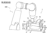
- the robot 300 includes a robot body 1 and a robot hand 7 as shown in FIG.
- the robot 300 is configured to transport the workpiece 4 placed on the pallet 8.
- the robot body 1 is composed of a vertical articulated robot.
- the robot hand 7 is attached to the tip of the robot body 1.
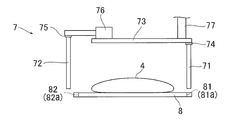
- the pallet 8 is formed in a plate shape having a substantially rectangular outer shape. Further, the pallet 8 is configured such that the workpiece 4 conveyed by the robot 300 is placed thereon.
- the pallet 8 includes a first side surface 81 disposed on one short side of the substantially rectangular shape and a second side surface 82 disposed on the other short side.
- the first side surface 81 has two first notches 81a.
- two second cutout portions 82 a are formed on the second side surface 82.
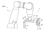
- the robot hand 7 includes a pair of first contact portions 71, a pair of second contact portions 72, a plate-like portion 73, a beam portion 74, and a beam portion 75.
- the air cylinder 76 and the mounting bracket 77 are included.
- the robot hand 7 is configured to hold the pallet 8 between the pair of first contact portions 71 and the pair of second contact portions 72. Specifically, the robot hand 7 is configured to hold the substantially rectangular pallet 8 in a direction in which the long side extends by the pair of first contact portions 71 and the pair of second contact portions 72. Yes. The robot hand 7 is configured to hold the pallet 8 while being lowered from the upper side. The robot hand 7 is configured to hold the pallet 8 between a pair of first contact portions 71 and a pair of second contact portions 72 at four support points.
- the first contact portion 71 and the second contact portion 72 are formed in a rod shape. Further, the rod-shaped first contact portion 71 and the second contact portion 72 are configured to descend from the upper side of the pallet 8 and hold the first side surface 81 and the second side surface 82 of the pallet 8.
- the pair of first contact portions 71 and the pair of second contact portions 72 are configured such that the interval changes in the direction in which the pallet 8 is sandwiched. Specifically, as shown in FIG. 15, the pair of first contact portions 71 are fixed to the plate-like portion 73 via the beam portions 74. On the other hand, the pair of second contact portions 72 is connected to an air cylinder 76 attached to the plate-like portion 73 via a beam portion 75. Thus, by driving the air cylinder 76, the distance between the pair of first contact portions 71 and the pair of second contact portions 72 is changed.
- the mounting bracket 77 connects the plate-like portion 73 and the tip of the robot body 1.
- the pair of first contact portions 71 of the robot hand 7 moves to the upper side of the pallet 8 so as to fit into the two first notches 81 a of the first side surface 81 of the pallet 8. Is done. Then, as shown in FIG. 18, the robot hand 7 is lowered so that the pair of first contact portions 71 fit into the two first notches 81 a of the pallet 8 and the pair of second contact portions 72. Is moved to a position facing the two second notches 82 a of the pallet 8. Thereafter, the air cylinder 76 is driven so that the pair of second contact portions 72 are in contact with the second side surface 82 (second notch portion 82 a) of the pallet 8. Thus, the pallet 8 is sandwiched and held by the pair of first contact portions 71 and the pair of second contact portions 72. *
- the remaining configuration of the third embodiment is the same as that of the first embodiment.
- the pair of first contact portions 71 that contact the first side surface 81 of the pallet 8 and the first of the pallet 8 By holding the pallet 8 on which the workpiece 4 is placed between the pair of second abutting portions 72 that abut against the second side surface 82 on the opposite side of the one side surface 81, the workpiece 4 has a shape that is difficult to grip. Even in this case, the pallet 8 on which the workpiece 4 is placed can be gripped by using the pair of first contact portions 71 and the pair of second contact portions 72 of the robot hand 7, and thus has a shape that is difficult to grip. The workpiece 4 can be conveyed.
- the first side surface 81 and the second side surface 82 are arranged on the short sides of the substantially rectangular pallet 8, respectively, and the pair of first contact portions 71 and the pair of first side surfaces are disposed.
- the substantially rectangular pallet 8 is sandwiched and held in the direction in which the long side extends by the two contact portions 72.
- the pallet 8 can be easily held by sandwiching the first side surface 81 and the second side surface 82 of the short side of the pallet 8 in the extending direction of the long side. Can be held.
- the first contact portion 71 and the second contact portion 72 are formed in a rod shape, and the rod-shaped first contact portion 71 and the second contact portion 72 are
- the pallet 8 is configured to descend from the upper side and hold the first side surface 81 and the second side surface 82 of the pallet 8. Thereby, the pallet 8 can be held without the first contact portion 71 and the second contact portion 72 of the robot hand 7 interfering with the workpiece 4 placed on the pallet 8.
- the first notch portion is formed on the first side surface of the pallet and the second notch portion is formed on the second side surface. It is not necessary to form a part (a 1st notch part and a 2nd notch part).
- the pallet has a substantially rectangular shape having a long side and a short side.
- the pallet may have a substantially square shape.
- the pallet is held between four support points by the first contact portion and the second contact portion.
- the pallet is held in the first contact portion.
- the pallet is held between three support points by the first contact portion and the second contact portion, but the pallet is supported by five or more support points or two support points by the first contact portion and the second contact portion. It may be held between.
- the workpiece includes two types of the first workpiece and the second workpiece.
- the number of workpieces may be one or three or more.
- one of the three support points is in contact with the pallet positioning part.
- two or three support points are in contact with the pallet positioning part. May be.
- a positioning part is formed only in one side of a 1st side surface or a 2nd side surface. May be.
- the example in which the first contact portion is in contact with the first side surface of the pallet in a state where the first contact portion is inclined with respect to the pallet has been described. You may make it contact
Landscapes
- Engineering & Computer Science (AREA)
- Robotics (AREA)
- Mechanical Engineering (AREA)
- Manipulator (AREA)
Abstract
このロボットハンド(2)は、ワーク(4)が載置された略矩形形状のパレット(3)の第1側面(31)に当接する第1当接部(21a)と、略矩形形状のパレットの第1側面の対辺側の第2側面(32)に当接する第2当接部(22a)とを備える。そして、ロボットハンドは、パレットを第1当接部および第2当接部により挟んで保持するように構成されている。
Description
この発明は、ロボットハンドおよびロボットに関する。
従来、ロボットハンドが知られている。このようなロボットハンドは、たとえば、特開平8-57788号公報に開示されている。
上記特開平8-57788号公報に開示されている把持装置(ロボットハンド)は、ブラウン管のように上下方向に把持することが困難なワークに対して、吸盤によりブラウン管の蛍光面を下から支持するとともに、保持プレートによりネック部を挟み込んでブラウン管を把持するように構成されている。
しかしながら、上記特開平8-57788号公報の把持装置では、吸盤によりブラウン管の蛍光面を下から支持するとともに、保持プレートによりネック部を挟み込んでブラウン管を把持するように構成されているため、蛍光面やネック部などの支持または把持する位置が特定できないワークを把持することが困難であり、このような把持しにくい形状を有するワークを搬送することが困難であるという問題点がある。
この発明は、上記のような課題を解決するためになされたものであり、この発明の1つの目的は、把持しにくい形状を有するワークを搬送することが可能なロボットハンドおよびロボットを提供することである。
上記目的を達成するために、第1の局面によるロボットハンドは、ワークが載置された略矩形形状のパレットの第1側面に当接する第1当接部と、略矩形形状のパレットの第1側面の対辺側の第2側面に当接する第2当接部とを備え、パレットを第1当接部および第2当接部により挟んで保持するように構成されている。
第1の局面によるロボットハンドでは、上記のように、パレットの第1側面に当接する第1当接部と、パレットの第1側面の対辺側の第2側面に当接する第2当接部とによりワークが載置されたパレットを挟んで保持することによって、ワーク自体が把持しにくい形状を有する場合でも、ワークが載置されたパレットをロボットハンドの第1当接部および第2当接部を用いて把持することができるので、把持しにくい形状を有するワークを搬送することができる。
第2の局面によるロボットは、多関節のロボット本体と、多関節のロボット本体の先端に取り付けられたロボットハンドとを備え、ロボットハンドは、ワークが載置された略矩形形状のパレットの第1側面に当接する第1当接部と、略矩形形状のパレットの第1側面の対辺側の第2側面に当接する第2当接部とを含み、パレットを第1当接部および第2当接部により挟んで保持するように構成されている。
第2の局面によるロボットでは、上記のように、パレットの第1側面に当接する第1当接部と、パレットの第1側面の対辺側の第2側面に当接する第2当接部とによりワークが載置されたパレットを挟んで保持することによって、ワーク自体が把持しにくい形状を有する場合でも、ワークが載置されたパレットをロボットハンドの第1当接部および第2当接部を用いて把持することができるので、把持しにくい形状を有するワークを搬送することが可能なロボットを提供することができる。
上記ロボットハンドおよびロボットによれば、把持しにくい形状を有するワークを搬送することができる。
以下、実施形態を図面に基づいて説明する。
(第1実施形態)
まず、図1~図3を参照して、第1実施形態によるロボット100の構成について説明する。
図1に示すように、ロボット100は、ロボット本体1と、ロボットハンド2とを備える。また、ロボット100は、パレット3に載置されたワーク4を搬送するように構成されている。ロボット本体1は、垂直多関節ロボットにより構成されている。また、ロボットハンド2は、ロボット本体1の先端に取り付けられている。
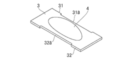
図3に示すように、パレット3は、略矩形形状の外形を有する板状に形成されている。また、パレット3は、ロボット100により搬送されるワーク4が載置されるように構成されている。また、パレット3は、略矩形形状の一方の長辺に配置された第1側面31と、他方の長辺に配置された第2側面32とを含む。また、第1側面31には、第1切欠き部31aが形成されている。また、第2側面32には、第2切欠き部32aが形成されている。
パレット3に載置されたワーク4は、たとえば、把持しにくい不定形状の物体などである。また、図1に示すように、ワーク4は、互いに異なる形状を有する第1ワーク4aおよび第2ワーク4bを含む。第1ワーク4aおよび第2ワーク4bは、それぞれ、同一の形状を有する共通のパレット3に載置されている。
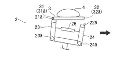
図1および図2に示すように、ロボットハンド2は、第1支持部21と、第2支持部22と、板状部23と、板状部24と、リンク部25と、バネ26と、検知部27と、連結部28と、取付ブラケット29とを含む。また、第1支持部21には、2つの第1当接部21aが設けられている。また、第2支持部22には、2つの第2当接部22aが設けられている。また、第1支持部21、第2支持部22、板状部23、板状部24、リンク部25、バネ26および検知部27は、それぞれ、2組ずつ設けられている。なお、バネ26は、「付勢部材」の一例である。
ここで、第1実施形態では、ロボットハンド2は、パレット3を第1当接部21aおよび第2当接部22aにより挟んで保持するように構成されている。具体的には、ロボットハンド2は、第1当接部21aおよび第2当接部22aにより略矩形形状のパレット3を短辺の延びる方向に挟んで保持するように構成されている。また、ロボットハンド2は、パレット3を下側から保持するように構成されている。
また、ロボットハンド2は、パレット3を2つの第1当接部21aおよび2つの第2当接部22aにより4点の支持点で挟んで保持するように構成されている。また、ロボットハンド2は、第1ワーク4aおよび第2ワーク4bがそれぞれ載置された共通のパレット3を第1当接部21aおよび第2当接部22aにより挟んで保持するように構成されている。
図1および図2に示すように、第1支持部21は、パレット3の長辺方向に延びるように形成されている。また、第1支持部21は、パレット3の第1側面31側を下側から支持するように構成されている。第2支持部22は、パレット3の長辺方向に延びるように形成されている。また、第2支持部22は、パレット3の第2側面32側を下側から支持するように構成されている。
図2に示すように、第1当接部21aは、第1支持部21から上方に突出するように形成されている。また、第1当接部21aは、第1支持部21の両端に配置されている。また、第1当接部21aは、図1に示すように、ワーク4が載置された略矩形形状のパレット3の第1側面31に当接するように構成されている。具体的には、第1当接部21aは、略矩形形状のパレット3の第1側面31に設けられた第1切欠き部31aに当接するように構成されている。また、第1当接部21aは、パレット3の第1切欠き部31aに嵌り込んで、第1当接部21aおよび第2当接部22aがパレット3を挟む方向と交差する方向の移動が規制されるように構成されている。
図2に示すように、第2当接部22aは、第2支持部22から上方に突出するように形成されている。また、第2当接部22aは、第2支持部22の両端に配置されている。また、第2当接部22aは、図1に示すように、ワーク4が載置された略矩形形状のパレット3の第2側面32に当接するように構成されている。具体的には、第2当接部22aは、略矩形形状のパレット3の第2側面32に設けられた第2切欠き部32aに当接するように構成されている。また、第2当接部22aは、パレット3の第2切欠き部32aに嵌り込んで、第1当接部21aおよび第2当接部22aがパレット3を挟む方向と交差する方向の移動が規制されるように構成されている。
第1当接部21aおよび第2当接部22aは、パレット3の長辺の延びる方向に沿って2セット設けられている。これにより、ロボットハンド2は、2セットの第1当接部21aおよび第2当接部22aにより、それぞれ、パレット3の長辺の延びる方向に沿って配置された2つのパレット3を同時に保持することが可能に構成されている。
また、第1当接部21aおよび第2当接部22aは、パレット3を挟み込む方向において、間隔を変化させることが可能なように構成されている。具体的には、図2に示すように、第1当接部21aは、第1支持部21を介して板状部23に接続されている。また、第2当接部22aは、第2支持部22を介して板状部24に接続されている。板状部23および板状部24は、図4に示すように、それぞれ、回動軸23aおよび24aを介してリンク部25の両端に回動可能に接続されている。また、板状部23および板状部24は、バネ26により接続されており、パレット3を挟む方向に互いに付勢されている。
検知部27は、第1当接部21aおよび第2当接部22aによりパレット3が保持されていることを検知するように構成されている。検知部27は、たとえば、パレット3によりスイッチがONにされて、保持されたパレット3を検知するように構成されている。
連結部28は、2組の第1支持部21、第2支持部22、板状部23、板状部24、リンク部25、バネ26および検知部27を、互いに連結している。具体的には、連結部28は、第1支持部21および第2支持部22の延びる方向に延びるように形成されている。また、連結部28は、両端に2つのリンク部25が取り付けられている。また、連結部28の中央付近には、取付ブラケット29が取り付けられている。また、取付ブラケット29は、ロボット本体1の先端に取り付けられている。
次に、図4~図6を参照して、第1実施形態によるロボット100のパレット3を保持する動作について説明する。
まず、図4に示すように、ロボットハンド2の第1当接部21aが、パレット3に対して傾けた状態でパレット3の第1側面31(第1切欠き部31a)に当接される。そして、図5に示すように、バネ26の付勢力に抗するように第2当接部22aと第1当接部21aとの間隔を広げるようにロボットハンド2が移動される。その後、図6に示すように、第2当接部22aがパレット3の第2側面32(第2切欠き部32a)に当接するようにロボットハンド2が移動される。これにより、バネ26の付勢力によりパレット3が第1当接部21aおよび第2当接部22aにより挟み込まれる。
次に、図7および図8を参照して、第1実施形態によるロボット100のパレット3を放す動作について説明する。
まず、図7に示すように、バネ26の付勢力に抗するように第2当接部22aと第1当接部21aとの間隔を広げるようにロボットハンド2が移動される。そして、図8に示すように、第1当接部21aがパレット3の第1側面31(第1切欠き部31a)に当接した状態で、第1当接部21をパレット3に対して傾ける。その後、第1当接部21aをパレット3の第1側面31(第1切欠き部31a)から離すようにロボットハンド2が移動される。これにより、パレット3がロボットハンド2から放される。
第1実施形態では、以下のような効果を得ることができる。
第1実施形態では、上記のように、パレット3の第1側面31に当接する第1当接部21aと、パレット3の第1側面31の対辺側の第2側面32に当接する第2当接部22aとによりワーク4(4a、4b)が載置されたパレット3を挟んで保持することによって、ワーク4自体が把持しにくい形状を有する場合でも、ワーク4が載置されたパレット3をロボットハンド2の第1当接部21aおよび第2当接部22aにより把持することができるので、把持しにくい形状を有するワーク4を搬送することができる。
また、第1実施形態では、上記のように、第1当接部21aを、略矩形形状のパレット3の第1側面31に設けられた第1切欠き部31aに当接するように構成し、第2当接部22aを、略矩形形状のパレット3の第2側面32に設けられた第2切欠き部32aに当接するように構成する。これにより、第1当接部21aおよび第2当接部22aを、それぞれ、第1切欠き部31aおよび第2切欠き部32aに当接させて、パレット3に対して第1当接部21aおよび第2当接部22aがずれるのを抑制することができる。
また、第1実施形態では、上記のように、第1当接部21aが、パレット3の第1切欠き部31aに嵌り込んで、第1当接部21aおよび第2当接部22aがパレット3を挟む方向と交差する方向の移動が規制されるように構成し、第2当接部22aが、パレット3の第2切欠き部32aに嵌り込んで、第1当接部21aおよび第2当接部22aがパレット3を挟む方向と交差する方向の移動が規制されるように構成する。これにより、第1当接部21aおよび第2当接部22aを、それぞれ、第1切欠き部31aおよび第2切欠き部32aに嵌りこませて、パレット3を挟む方向と交差する方向に第1当接部21aおよび第2当接部22aがパレット3に対してずれるのを確実に抑制することができる。
また、第1実施形態では、上記のように、パレット3を第1当接部21aおよび第2当接部22aにより4点の支持点で挟んで保持するように構成する。これにより、略矩形のパレット3を4点の支持点でバランスよく挟んで、ロボットハンド2によりパレット3を水平にバランスよく保持することができる。
また、第1実施形態では、上記のように、ワーク4aおよびワーク4b(図1参照)は、それぞれ、同一の形状を有する共通のパレット3に載置されており、ワーク4aおよびワーク4bがそれぞれ載置された共通のパレット3を第1当接部21aおよび第2当接部22aにより挟んで保持するように構成する。これにより、ワーク4aとワーク4bとが互いに異なる形状を有する場合でも、同一の形状のパレット3にワーク4aおよびワーク4bを載置することができるので、ワーク毎に異なる形状のパレットを準備する手間を省くことができる。
また、第1実施形態では、上記のように、第1当接部21aおよび第2当接部22aによりパレット3が保持されていることを検知する検知部27を設ける。これにより、ロボットハンド2によりパレット3を保持していることを検知部27により確実に検知することができる。
また、第1実施形態では、上記のように、第1側面31および第2側面32は、略矩形形状のパレット3の長辺にそれぞれ配置されており、第1当接部21aおよび第2当接部22aにより略矩形形状のパレット3を短辺の延びる方向に挟んで保持するように構成する。これにより、パレット3の長辺方向に隣接して別の物体がある場合でも、パレット3の長辺の第1側面31および第2側面32を短辺の延びる方向に挟んで容易にパレット3を保持することができる。
また、第1実施形態では、上記のように、第1当接部21aおよび第2当接部22aを、パレット3の長辺の延びる方向に沿って2セット設け、2セットの第1当接部21aおよび第2当接部22aにより、それぞれ、パレット3の長辺の延びる方向に沿って配置された2つのパレット3を保持するように構成する。これにより、同時に2つのパレット3を搬送することができるので、タクトタイムを縮めることができる。
また、第1実施形態では、上記のように、第1当接部21aおよび第2当接部22aをパレット3を挟む方向に付勢するバネ26を設け、パレット3の第1側面31に第1当接部21aを当接させた状態で、バネ26の付勢力に抗するように第2当接部22aを第1当接部21aに対して間隔を広げるように移動させた後、バネ26の付勢力によりパレット3を第1当接部21aおよび第2当接部22aにより挟み込むように構成する。これにより、パレット3を保持するために、第1当接部21aと第2当接部22aとの間隔を変化させる駆動機構を設ける必要がないので、ロボットハンド2の構造を簡略化することができる。
また、第1実施形態では、上記のように、ロボットハンド2を、多関節のロボット本体1に取り付け、パレット3を第1当接部21aおよび第2当接部22aにより挟み込む際に、多関節のロボット本体1を用いて、第1当接部21aをパレット3に対して傾けた状態でパレット3の第1側面31に当接させて、バネ26の付勢力に抗するように第2当接部22aを第1当接部21aに対して間隔を広げるように移動させるように構成する。これにより、パレット3と第2当接部22aとが干渉することなく第1当接部21aと第2当接部22aとの間隔が広げられるので、パレット3を第1当接部21aおよび第2当接部22aにより容易に挟み込むことができる。
また、第1実施形態では、上記のように、パレット3の第1側面31側を下側から支持する第1支持部21と、パレット3の第2側面32側を下側から支持する第2支持部22とを設け、第1当接部21aを、第1支持部21から上方に突出するように形成し、第2当接部22aを、第2支持部22から上方に突出するように形成する。これにより、第1支持部21および第2支持部22によりパレット3を下側から支持しつつ、第1当接部21aおよび第2当接部22aにより挟み込んで保持することによって、パレット3をより確実に安定して保持することができるので、パレット3に載置されたワーク4をより安定して搬送することができる。
(第2実施形態)
次に、図9~図13を参照して、第2実施形態について説明する。この第2実施形態では、ロボットハンドによりパレットを下側から上昇して保持する第1実施形態とは異なり、ロボットハンドによりパレットを上側から下降して保持する例について説明する。
次に、図9~図13を参照して、第2実施形態について説明する。この第2実施形態では、ロボットハンドによりパレットを下側から上昇して保持する第1実施形態とは異なり、ロボットハンドによりパレットを上側から下降して保持する例について説明する。
第2実施形態によるロボット200は、図9に示すように、ロボット本体1と、ロボットハンド5とを備える。また、ロボット200は、パレット6に載置されたワーク4を搬送するように構成されている。ロボット本体1は、垂直多関節ロボットにより構成されている。また、ロボットハンド5は、ロボット本体1の先端に取り付けられている。
図11に示すように、パレット6は、略矩形形状の外形を有する板状に形成されている。また、パレット6は、ロボット200により搬送されるワーク4が載置されるように構成されている。また、パレット6は、略矩形形状の一方の長辺に配置された第1側面61と、他方の長辺に配置された第2側面62とを含む。また、第1側面61には、第1切欠き部61aが形成されている。また、第1側面61には、第1切欠き部61aの中央部に三角形状に切り欠かれた位置決め部61bが形成されている。また、第2側面62には、第2切欠き部62aが形成されている。また、第2側面62には、第2切欠き部62aの中央部に三角形状に切り欠かれた位置決め部62bが形成されている。
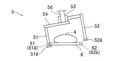
図9および図10に示すように、ロボットハンド5は、2つの第1当接部51と、1つの第2当接部52と、エアシリンダ53と、板状部54と、検知部55と、取付ブラケット56とを含む。また、第1当接部51の先端には、第1落下防止部51aが設けられている。また、第2当接部52の先端には、第2落下防止部52aが設けられている。
ここで、第2実施形態では、ロボットハンド5は、パレット6を2つの第1当接部51および1つの第2当接部52により挟んで保持するように構成されている。具体的には、ロボットハンド5は、第1当接部51および第2当接部52により略矩形形状のパレット6を短辺の延びる方向に挟んで保持するように構成されている。また、ロボットハンド5は、パレット6を上側から保持するように構成されている。
また、ロボットハンド5は、パレット6を2つの第1当接部51および1つの第2当接部52により3点の支持点で挟んで保持するように構成されている。具体的には、2つの第1当接部51は、略矩形形状のパレット6の長辺に配置された第1側面61の2箇所に当接するように構成されている。また、1つの第2当接部52は、略矩形形状のパレット6の第1側面61と反対側の長辺に配置された第2側面62の1箇所に当接するように構成されている。
すなわち、2つの第1当接部51が、それぞれ、パレット6の第1側面61の第1切欠き部61aに当接するとともに、第2当接部52がパレット6の第2側面62の位置決め部62bに当接するように構成されている。また、パレット6の向きが左右逆の場合は、2つの第1当接部51が、それぞれ、パレット6の第2側面62の第2切欠き部62aに当接するとともに、第2当接部52がパレット6の第1側面61の位置決め部61bに当接するように構成されている。これにより、ロボットハンド5に対してパレット6が位置決めされて保持される。
第1当接部51および第2当接部52は、棒状に形成されている。また、棒状の第1当接部51および第2当接部52は、パレット6の上側から下降してパレット6の第1側面61および第2側面62を保持するように構成されている。
第1落下防止部51aは、棒状の2つの第1当接部51の先端近傍に設けられている。また、第1落下防止部51aは、パレット6を挟む方向側に突出することによりパレット6の落下を防止するように構成されている。第2落下防止部52aは、棒状の1つの第2当接部52の先端近傍に設けられている。また、第2落下防止部52aは、パレット6を挟む方向側に突出することによりパレット6の落下を防止するように構成されている。
また、第1当接部51および第2当接部52は、パレット6を挟み込む方向において、間隔が変化するように構成されている。具体的には、図10に示すように、第1当接部51は、板状部52に固定されている。一方、第2当接部52は、板状部52に取り付けられたエアシリンダ53に接続されている。これにより、エアシリンダ53を駆動することにより、第1当接部51および第2当接部52の間隔が変化するように構成されている。
検知部55は、第1当接部51および第2当接部52によりパレット6が保持されていることを検知するように構成されている。検知部55は、たとえば、光電センサにより保持されたパレット3を検知するように構成されている。取付ブラケット56は、板状部54と、ロボット本体1の先端とを接続している。
次に、図12および図13を参照して、第2実施形態によるロボット200のパレット6を保持する動作について説明する。
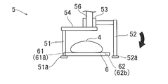
まず、図12に示すように、ロボットハンド5の2つの第1当接部51が、パレット6に対して傾いた状態でパレット6の第1側面61(第1切欠き部61a)に当接される。そして、図13に示すように、ロボットハンド5を回転させて、第2当接部52がパレット6の第2側面62(位置決め部62b)に対向する位置に移動される。その後、エアシリンダ53を駆動して、1つの第2当接部52がパレット6の第2側面62(位置決め部62b)に当接される。これにより、2つの第1当接部51および1つの第2当接部52によりパレット6が挟み込まれて保持される。
なお、第2実施形態のその他の構成は、上記第1実施形態と同様である。
第2実施形態では、以下のような効果を得ることができる。
上記のように、第2実施形態の構成においても、上記第1実施形態と同様に、パレット6の第1側面61に当接する第1当接部51と、パレット6の第1側面61の対辺側の第2側面62に当接する第2当接部52とによりワーク4が載置されたパレット6を挟んで保持することによって、ワーク4自体が把持しにくい形状を有する場合でも、ワーク4が載置されたパレット6をロボットハンド5の2つの第1当接部51および1つの第2当接部52を用いて把持することができるので、把持しにくい形状を有するワーク4を搬送することができる。
さらに、第2実施形態では、上記のように、第1当接部51を、略矩形形状のパレット6の長辺に配置された第1側面61の2箇所に当接するように構成し、第2当接部52を、略矩形形状のパレット6の第1側面61と反対側の長辺に配置された第2側面62の1箇所に当接するように構成し、パレット6を第1当接部51および第2当接部52により挟んで3点の支持点で保持するように構成する。これにより、3点の支持点によりパレット6を安定して保持することができる。
また、第2実施形態では、上記のように、第1当接部51および第2当接部52を、3点の支持点のうち1点がパレット6の位置決め部62bに当接して、パレット6に対する位置決めが行われるように構成する。これにより、パレット6を正確に位置決めして保持することができるので、搬送されるワーク4への作業の精度を向上させることができる。
また、第2実施形態では、上記のように、第1当接部51および第2当接部52を、棒状に形成し、棒状の第1当接部51および第2当接部52を、パレット6の上側から下降してパレット6の第1側面61および第2側面62を保持するように構成する。これにより、ロボットハンド5の第1当接部51および第2当接部52がパレット6に載置されたワーク4に干渉することなくパレット6を保持することができる。
また、第2実施形態では、上記のように、棒状の第1当接部51の先端近傍にパレット6を挟む方向側に突出することによりパレット6の落下を防止する第1落下防止部51aと、棒状の第2当接部52の先端近傍にパレット6を挟む方向側に突出することによりパレット6の落下を防止する第2落下防止部52aとを設ける。これにより、第1落下防止部51aおよび第2落下防止部52aによりパレット6を下側から支持しつつ、第1当接部51および第2当接部52により挟み込んで保持することによって、パレット6をより確実に安定して保持することができるので、パレット6に載置されたワーク4をより安定して搬送することができる。
また、第2実施形態では、上記のように、ロボットハンド5を、多関節のロボット本体1に取り付け、パレット6を第1当接部51および第2当接部52により挟み込む際に、多関節のロボット本体1を用いて、第1当接部51をパレット6に対して傾けた状態でパレット6の第1側面61に当接させるように構成する。これにより、パレット6と第2当接部52の先端近傍の第2落下防止部52aとが干渉することなく第1当接部51をパレット6の第1側面61に当接させることができるので、パレット6を第1当接部51および第2当接部52により容易に挟み込むことができる。
なお、第2実施形態のその他の効果は、上記第1実施形態と同様である。
(第3実施形態)
次に、図14~図18を参照して、第3実施形態について説明する。この第3実施形態では、パレットの短辺方向にパレットを挟み込んで保持する第1および第2実施形態とは異なり、パレットの長辺方向にパレットを挟み込んで保持する例について説明する。
次に、図14~図18を参照して、第3実施形態について説明する。この第3実施形態では、パレットの短辺方向にパレットを挟み込んで保持する第1および第2実施形態とは異なり、パレットの長辺方向にパレットを挟み込んで保持する例について説明する。
第3実施形態によるロボット300は、図14に示すように、ロボット本体1と、ロボットハンド7とを備える。また、ロボット300は、パレット8に載置されたワーク4を搬送するように構成されている。ロボット本体1は、垂直多関節ロボットにより構成されている。また、ロボットハンド7は、ロボット本体1の先端に取り付けられている。
図16に示すように、パレット8は、略矩形形状の外形を有する板状に形成されている。また、パレット8は、ロボット300により搬送されるワーク4が載置されるように構成されている。また、パレット8は、略矩形形状の一方の短辺に配置された第1側面81と、他方の短辺に配置された第2側面82とを含む。また、第1側面81には、2つの第1切欠き部81aが形成されている。また、第2側面82には、2つの第2切欠き部82aが形成されている。
図14および図15に示すように、ロボットハンド7は、一対の第1当接部71と、一対の第2当接部72と、板状部73と、梁部74と、梁部75と、エアシリンダ76と、取付ブラケット77とを含む。
ここで、第3実施形態では、ロボットハンド7は、パレット8を一対の第1当接部71および一対の第2当接部72により挟んで保持するように構成されている。具体的には、ロボットハンド7は、一対の第1当接部71および一対の第2当接部72により略矩形形状のパレット8を長辺の延びる方向に挟んで保持するように構成されている。また、ロボットハンド7は、パレット8を上側から下降して保持するように構成されている。また、ロボットハンド7は、パレット8を一対の第1当接部71および一対の第2当接部72により4点の支持点で挟んで保持するように構成されている。
第1当接部71および第2当接部72は、棒状に形成されている。また、棒状の第1当接部71および第2当接部72は、パレット8の上側から下降してパレット8の第1側面81および第2側面82を保持するように構成されている。
また、一対の第1当接部71および一対の第2当接部72は、パレット8を挟み込む方向において、間隔が変化するように構成されている。具体的には、図15に示すように、一対の第1当接部71は、梁部74を介して板状部73に固定されている。一方、一対の第2当接部72は、板状部73に取り付けられたエアシリンダ76に梁部75を介して接続されている。これにより、エアシリンダ76を駆動することにより、一対の第1当接部71および一対の第2当接部72の間隔が変化するように構成されている。
取付ブラケット77は、板状部73と、ロボット本体1の先端とを接続している。
次に、図17および図18を参照して、第3実施形態によるロボット300のパレット8を保持する動作について説明する。
まず、図17に示すように、ロボットハンド7の一対の第1当接部71が、パレット8の第1側面81の2つの第1切欠き部81aに嵌り込むようにパレット8の上側に移動される。そして、図18に示すように、ロボットハンド7を下降させて、一対の第1当接部71がパレット8の2つの第1切欠き部81aに嵌り込むとともに、一対の第2当接部72がパレット8の2つの第2切欠き部82aに対向する位置に移動される。その後、エアシリンダ76を駆動して、一対の第2当接部72がパレット8の第2側面82(第2切欠き部82a)に当接される。これにより、一対の第1当接部71および一対の第2当接部72によりパレット8が挟み込まれて保持される。
なお、第3実施形態のその他の構成は、上記第1実施形態と同様である。
第3実施形態では、以下のような効果を得ることができる。
上記のように、第3実施形態の構成においても、上記第1および第2実施形態と同様に、パレット8の第1側面81に当接する一対の第1当接部71と、パレット8の第1側面81の対辺側の第2側面82に当接する一対の第2当接部72とによりワーク4が載置されたパレット8を挟んで保持することにより、ワーク4が把持しにくい形状を有する場合でも、ワーク4が載置されたパレット8をロボットハンド7の一対の第1当接部71および一対の第2当接部72を用いて把持することができるので、把持しにくい形状を有するワーク4を搬送することができる。
さらに、第3実施形態では、上記のように、第1側面81および第2側面82を、略矩形形状のパレット8の短辺にそれぞれ配置し、一対の第1当接部71および一対の第2当接部72により略矩形形状のパレット8を長辺の延びる方向に挟んで保持するように構成する。これにより、パレット8の短辺方向に隣接して別の物体がある場合でも、パレット8の短辺の第1側面81および第2側面82を長辺の延びる方向に挟んで容易にパレット8を保持することができる。
また、第3実施形態では、上記のように、第1当接部71および第2当接部72を、棒状に形成し、棒状の第1当接部71および第2当接部72を、パレット8の上側から下降してパレット8の第1側面81および第2側面82を保持するように構成する。これにより、ロボットハンド7の第1当接部71および第2当接部72がパレット8に載置されたワーク4に干渉することなくパレット8を保持することができる。
なお、第3実施形態のその他の効果は、上記第1実施形態と同様である。
なお、今回開示された実施形態は、すべての点で例示であって制限的なものではないと考えられるべきである。本発明の範囲は、上記した実施形態の説明ではなく請求の範囲によって示され、さらに請求の範囲と均等の意味および範囲内でのすべての変更が含まれる。
たとえば、上記第1~第3実施形態では、パレットの第1側面に第1切欠き部を形成するとともに、第2側面に第2切欠き部を形成する例を示したが、パレットに切欠き部(第1切欠き部および第2切欠き部)を形成しなくてもよい。
また、上記第1~第3実施形態では、パレットが長辺および短辺を有する略長方形形状を有する例を示したが、パレットは略正方形形状を有していてもよい。
また、上記第1および第3実施形態では、パレットを第1当接部および第2当接部により4点の支持点で挟んで保持し、上記第2実施形態では、パレットを第1当接部および第2当接部により3点の支持点で挟んで保持する例を示したが、パレットを第1当接部および第2当接部により5点以上の支持点または2点の支持点で挟んで保持してもよい。
また、上記第1実施形態では、ワークが2種類の第1ワークおよび第2ワークを含む例を示したが、ワークの種類は、1種類でもよいし、3種類以上でもよい。
また、上記第1実施形態では、2セットの第1当接部および第2当接部により2つのパレットを保持する例を示したが、3セット以上の第1当接部および第2当接部により3つ以上のパレットを保持するようにしてもよい。
また、上記第2実施形態では、3点の支持点のうち1点がパレットの位置決め部に当接する例を示したが、2点または3点の支持点がパレットの位置決め部に当接するようにしてもよい。
また、上記第2実施形態では、パレットの第1側面および第2側面の両方に位置決め部を形成する構成の例を示したが、第1側面または第2側面の片方のみに位置決め部を形成してもよい。
また、上記第2実施形態では、パレットに切欠き部(第1切欠き部および第2切欠き部)と、位置決め部とを形成する構成の例を示したが、パレットに切欠き部または位置決め部のいずれかのみを形成してもよい。
また、上記第2実施形態では、第1当接部および第2当接部の全てに落下防止部(第1落下防止部および第2落下防止部)を設ける構成の例を示したが、第1当接部および第2当接部の一部に落下防止部を設けてもよい。
また、上記第1および第2実施形態では、第1当接部をパレットに対して傾けた状態でパレットの第1側面に当接させる構成の例を示したが、第1当接部をパレットに対して垂直に立てた状態でパレットの第1側面に当接させてもよい。
1 ロボット本体
2、5、7 ロボットハンド
3、6、8 パレット
4 ワーク
4a ワーク(第1ワーク)
4b ワーク(第2ワーク)
21 第1支持部
21a、51、71 第1当接部
22 第2支持部
22a、52、72 第2当接部
26 バネ(付勢部材)
27、55 検知部
31、61、81 第1側面
31a、61a、81a 第1切欠き部
32、62、82 第2側面
32a、82a 第2切欠き部
51a 第1落下防止部
52a 第2落下防止部
62b 位置決め部
100、200、300 ロボット
2、5、7 ロボットハンド
3、6、8 パレット
4 ワーク
4a ワーク(第1ワーク)
4b ワーク(第2ワーク)
21 第1支持部
21a、51、71 第1当接部
22 第2支持部
22a、52、72 第2当接部
26 バネ(付勢部材)
27、55 検知部
31、61、81 第1側面
31a、61a、81a 第1切欠き部
32、62、82 第2側面
32a、82a 第2切欠き部
51a 第1落下防止部
52a 第2落下防止部
62b 位置決め部
100、200、300 ロボット
Claims (20)
- ワーク(4、4a、4b)が載置された略矩形形状のパレット(3、6、8)の第1側面(31、61、81)に当接する第1当接部(21a、51、71)と、
前記略矩形形状のパレットの第1側面の対辺側の第2側面(32、62、82)に当接する第2当接部(22a、52、72)とを備え、
前記パレットを前記第1当接部および前記第2当接部により挟んで保持するように構成されている、ロボットハンド。 - 前記第1当接部は、前記略矩形形状のパレットの前記第1側面に設けられた第1切欠き部(31a、61a、81a)に当接するように構成されており、
前記第2当接部は、前記略矩形形状のパレットの前記第2側面に設けられた第2切欠き部(32a、82a)に当接するように構成されている、請求項1に記載のロボットハンド。 - 前記第1当接部は、前記パレットの前記第1切欠き部に嵌り込んで、前記第1当接部および前記第2当接部が前記パレットを挟む方向と交差する方向の移動が規制されるように構成されており、
前記第2当接部は、前記パレットの前記第2切欠き部に嵌り込んで、前記第1当接部および前記第2当接部が前記パレットを挟む方向と交差する方向の移動が規制されるように構成されている、請求項2に記載のロボットハンド。 - 前記パレットを前記第1当接部および前記第2当接部により3点以上の支持点で挟んで保持するように構成されている、請求項1に記載のロボットハンド。
- 前記ワークは、互いに異なる形状を有する第1ワーク(4a)および第2ワーク(4b)を含み、
前記第1ワークおよび前記第2ワークは、それぞれ、同一の形状を有する共通の前記パレットに載置されており、
前記第1ワークおよび前記第2ワークがそれぞれ載置された共通の前記パレットを前記第1当接部および前記第2当接部により挟んで保持するように構成されている、請求項1に記載のロボットハンド。 - 前記第1当接部および前記第2当接部により前記パレットが保持されていることを検知する検知部(27、55)をさらに備える、請求項1に記載のロボットハンド。
- 前記第1側面および前記第2側面は、前記略矩形形状のパレットの長辺にそれぞれ配置されており、
前記第1当接部および前記第2当接部により前記略矩形形状のパレットを短辺の延びる方向に挟んで保持するように構成されている、請求項1に記載のロボットハンド。 - 前記第1当接部および前記第2当接部は、前記パレットの長辺の延びる方向に沿って複数セット設けられており、
複数セットの前記第1当接部および前記第2当接部により、それぞれ、前記パレットの長辺の延びる方向に沿って配置された複数の前記パレットを保持するように構成されている、請求項7に記載のロボットハンド。 - 前記第1当接部および前記第2当接部を前記パレットを挟む方向に付勢する付勢部材(26)をさらに備え、
前記パレットの前記第1側面に前記第1当接部を当接させた状態で、前記付勢部材の付勢力に抗するように前記第2当接部を前記第1当接部に対して間隔を広げるように移動させた後、前記付勢部材の付勢力により前記パレットを前記第1当接部および前記第2当接部により挟み込むように構成されている、請求項7に記載のロボットハンド。 - 前記ロボットハンドは、多関節のロボット本体(1)に取り付けられており、
前記パレットを前記第1当接部および前記第2当接部により挟み込む際に、前記多関節のロボット本体を用いて、前記第1当接部を前記パレットに対して傾けた状態で前記パレットの前記第1側面に当接させて、前記付勢部材の付勢力に抗するように前記第2当接部を前記第1当接部に対して間隔を広げるように移動させるように構成されている、請求項9に記載のロボットハンド。 - 前記パレットの前記第1側面側を下側から支持する第1支持部(21)と、
前記パレットの前記第2側面側を下側から支持する第2支持部(22)とをさらに備え、
前記第1当接部は、前記第1支持部から上方に突出するように形成されており、
前記第2当接部は、前記第2支持部から上方に突出するように形成されている、請求項7に記載のロボットハンド。 - 前記第1当接部は、前記略矩形形状のパレットの長辺に配置された前記第1側面の2箇所に当接するように構成されており、
前記第2当接部は、前記略矩形形状のパレットの前記第1側面と反対側の長辺に配置された前記第2側面の1箇所に当接するように構成されており、
前記パレットを前記第1当接部および前記第2当接部により挟んで3点の支持点で保持するように構成されている、請求項1に記載のロボットハンド。 - 前記第1当接部および前記第2当接部は、3点の支持点のうち少なくとも1点が前記パレットの位置決め部(62b)に当接して、前記パレットに対する位置決めが行われるように構成されている、請求項12に記載のロボットハンド。
- 前記第1当接部および前記第2当接部は、棒状に形成されており、
棒状の前記第1当接部および前記第2当接部は、前記パレットの上側から下降して前記パレットの前記第1側面および前記第2側面を保持するように構成されている、請求項12に記載のロボットハンド。 - 棒状の前記第1当接部の先端近傍に設けられ、前記パレットを挟む方向側に突出することにより前記パレットの落下を防止する第1落下防止部(51a)と、
棒状の前記第2当接部の先端近傍に設けられ、前記パレットを挟む方向側に突出することにより前記パレットの落下を防止する第2落下防止部(52a)とをさらに備える、請求項12に記載のロボットハンド。 - 前記ロボットハンドは、多関節のロボット本体(1)に取り付けられており、
前記パレットを前記第1当接部および前記第2当接部により挟み込む際に、前記多関節のロボット本体を用いて、前記第1当接部を前記パレットに対して傾けた状態で前記パレットの前記第1側面に当接させるように構成されている、請求項15に記載のロボットハンド。 - 前記第1側面および前記第2側面は、前記略矩形形状のパレットの短辺にそれぞれ配置されており、
前記第1当接部および前記第2当接部により前記略矩形形状のパレットを長辺の延びる方向に挟んで保持するように構成されている、請求項1に記載のロボットハンド。 - 前記第1当接部および前記第2当接部は、棒状に形成されており、
棒状の前記第1当接部および前記第2当接部は、前記パレットの上側から下降して前記パレットの前記第1側面および前記第2側面を保持するように構成されている、請求項17に記載のロボットハンド。 - 多関節のロボット本体(1)と、
前記多関節のロボット本体の先端に取り付けられたロボットハンド(2、5、7)とを備え、
前記ロボットハンドは、
ワーク(4、4a、4b)が載置された略矩形形状のパレット(3、6、8)の第1側面(31、61、81)に当接する第1当接部(21a、51、71)と、
前記略矩形形状のパレットの第1側面の対辺側の第2側面(32、62、82)に当接する第2当接部(22a、52、72)とを含み、
前記パレットを前記第1当接部および前記第2当接部により挟んで保持するように構成されている、ロボット。 - 前記第1当接部は、前記略矩形形状のパレットの前記第1側面に設けられた第1切欠き部(31a、61a、81a)に当接するように構成されており、
前記第2当接部は、前記略矩形形状のパレットの前記第2側面に設けられた第2切欠き部(32a、82a)に当接するように構成されている、請求項19に記載のロボット。
Priority Applications (2)
| Application Number | Priority Date | Filing Date | Title |
|---|---|---|---|
| PCT/JP2013/072394 WO2015025399A1 (ja) | 2013-08-22 | 2013-08-22 | ロボットハンドおよびロボット |
| JP2015532650A JPWO2015025399A1 (ja) | 2013-08-22 | 2013-08-22 | ロボットハンドおよびロボット |
Applications Claiming Priority (1)
| Application Number | Priority Date | Filing Date | Title |
|---|---|---|---|
| PCT/JP2013/072394 WO2015025399A1 (ja) | 2013-08-22 | 2013-08-22 | ロボットハンドおよびロボット |
Publications (1)
| Publication Number | Publication Date |
|---|---|
| WO2015025399A1 true WO2015025399A1 (ja) | 2015-02-26 |
Family
ID=52483208
Family Applications (1)
| Application Number | Title | Priority Date | Filing Date |
|---|---|---|---|
| PCT/JP2013/072394 Ceased WO2015025399A1 (ja) | 2013-08-22 | 2013-08-22 | ロボットハンドおよびロボット |
Country Status (2)
| Country | Link |
|---|---|
| JP (1) | JPWO2015025399A1 (ja) |
| WO (1) | WO2015025399A1 (ja) |
Cited By (1)
| Publication number | Priority date | Publication date | Assignee | Title |
|---|---|---|---|---|
| JP2023170966A (ja) * | 2022-05-20 | 2023-12-01 | トヨタ自動車株式会社 | ロボットハンドおよび搬送システム |
Citations (13)
| Publication number | Priority date | Publication date | Assignee | Title |
|---|---|---|---|---|
| JPH0364276B2 (ja) * | 1987-11-06 | 1991-10-04 | Canon Kk | |
| JPH041838U (ja) * | 1990-04-19 | 1992-01-09 | ||
| JPH0550402B2 (ja) * | 1988-01-30 | 1993-07-29 | Canon Kk | |
| JPH0563791U (ja) * | 1992-02-05 | 1993-08-24 | 株式会社日研工作所 | ロボットハンド |
| JPH07503443A (ja) * | 1992-06-05 | 1995-04-13 | シーメンス アクチエンゲゼルシヤフト | 取扱い装置に対するつかみ範囲を備えた貯蔵容器 |
| JPH08206985A (ja) * | 1995-02-03 | 1996-08-13 | Meidensha Corp | ロボットハンド交換治具及び交換方法 |
| JPH1095374A (ja) * | 1996-09-24 | 1998-04-14 | Mazda Motor Corp | 物品搬送装置 |
| JPH1199496A (ja) * | 1997-09-30 | 1999-04-13 | Mazda Motor Corp | 板状部材の搬送装置および同搬送方法 |
| JPH11207561A (ja) * | 1998-01-30 | 1999-08-03 | Denso Corp | パレット交換システム |
| JPH11309637A (ja) * | 1998-04-30 | 1999-11-09 | Pentel Kk | 平行移動型チャック装置 |
| JP2000035460A (ja) * | 1998-05-11 | 2000-02-02 | Advantest Corp | トレイ移送ア―ム、電子部品試験装置およびトレイの搬送方法 |
| JP2002255315A (ja) * | 2001-02-26 | 2002-09-11 | Ando Electric Co Ltd | トレイ収容装置 |
| JP2002368058A (ja) * | 2001-06-04 | 2002-12-20 | Micronics Japan Co Ltd | 表示用基板の搬送装置 |
-
2013
- 2013-08-22 WO PCT/JP2013/072394 patent/WO2015025399A1/ja not_active Ceased
- 2013-08-22 JP JP2015532650A patent/JPWO2015025399A1/ja active Pending
Patent Citations (13)
| Publication number | Priority date | Publication date | Assignee | Title |
|---|---|---|---|---|
| JPH0364276B2 (ja) * | 1987-11-06 | 1991-10-04 | Canon Kk | |
| JPH0550402B2 (ja) * | 1988-01-30 | 1993-07-29 | Canon Kk | |
| JPH041838U (ja) * | 1990-04-19 | 1992-01-09 | ||
| JPH0563791U (ja) * | 1992-02-05 | 1993-08-24 | 株式会社日研工作所 | ロボットハンド |
| JPH07503443A (ja) * | 1992-06-05 | 1995-04-13 | シーメンス アクチエンゲゼルシヤフト | 取扱い装置に対するつかみ範囲を備えた貯蔵容器 |
| JPH08206985A (ja) * | 1995-02-03 | 1996-08-13 | Meidensha Corp | ロボットハンド交換治具及び交換方法 |
| JPH1095374A (ja) * | 1996-09-24 | 1998-04-14 | Mazda Motor Corp | 物品搬送装置 |
| JPH1199496A (ja) * | 1997-09-30 | 1999-04-13 | Mazda Motor Corp | 板状部材の搬送装置および同搬送方法 |
| JPH11207561A (ja) * | 1998-01-30 | 1999-08-03 | Denso Corp | パレット交換システム |
| JPH11309637A (ja) * | 1998-04-30 | 1999-11-09 | Pentel Kk | 平行移動型チャック装置 |
| JP2000035460A (ja) * | 1998-05-11 | 2000-02-02 | Advantest Corp | トレイ移送ア―ム、電子部品試験装置およびトレイの搬送方法 |
| JP2002255315A (ja) * | 2001-02-26 | 2002-09-11 | Ando Electric Co Ltd | トレイ収容装置 |
| JP2002368058A (ja) * | 2001-06-04 | 2002-12-20 | Micronics Japan Co Ltd | 表示用基板の搬送装置 |
Cited By (2)
| Publication number | Priority date | Publication date | Assignee | Title |
|---|---|---|---|---|
| JP2023170966A (ja) * | 2022-05-20 | 2023-12-01 | トヨタ自動車株式会社 | ロボットハンドおよび搬送システム |
| JP7632387B2 (ja) | 2022-05-20 | 2025-02-19 | トヨタ自動車株式会社 | ロボットハンドおよび搬送システム |
Also Published As
| Publication number | Publication date |
|---|---|
| JPWO2015025399A1 (ja) | 2017-03-02 |
Similar Documents
| Publication | Publication Date | Title |
|---|---|---|
| US8408619B2 (en) | Robot hand | |
| KR100832168B1 (ko) | 기판보유지지장치 | |
| KR102105580B1 (ko) | 기판 반송 장치 및 기판 반송 로봇의 교시 방법 | |
| CN105818156B (zh) | 搬运系统以及搬运方法 | |
| JP5303301B2 (ja) | 産業用ロボット | |
| CN103779260A (zh) | 夹持装置及工件输送机械手 | |
| JP2014103156A (ja) | 基板搬送ロボットおよび基板搬送方法 | |
| KR101697202B1 (ko) | 물품의 지지 장치 및 지지 장치에의 2 종류의 물품의 재치 방법 | |
| JP5746483B2 (ja) | 産業用ロボット | |
| JP2022059951A (ja) | 産業用ロボット | |
| WO2015025399A1 (ja) | ロボットハンドおよびロボット | |
| JP2012110992A (ja) | 荷搬送アームおよび荷搬送アームを備えた荷搬送ロボット | |
| JP2013107174A (ja) | 吸着装置 | |
| JP5467065B2 (ja) | ワークの搬送装置 | |
| JP6456065B2 (ja) | 産業用ロボットのハンドおよび産業用ロボット | |
| KR100962953B1 (ko) | 유리 기판 이송용 로봇 | |
| JP2014116536A (ja) | エンドエフェクタ装置及び該エンドエフェクタ装置を用いた板状部材の位置決め方法 | |
| WO2018151120A1 (ja) | 載置物の転倒防止装置 | |
| JP2022076061A (ja) | 産業用ロボット | |
| KR101989322B1 (ko) | 필름을 이송하기 위한 로봇 핸드 | |
| JP5992082B2 (ja) | ワーク検知装置 | |
| JP2007069316A (ja) | 物品搬送ロボット | |
| KR102059567B1 (ko) | 기판 반송 장치 | |
| JP4100677B2 (ja) | ワーク搬送ツール | |
| KR20110029705A (ko) | 기판 이송장치 |
Legal Events
| Date | Code | Title | Description |
|---|---|---|---|
| 121 | Ep: the epo has been informed by wipo that ep was designated in this application |
Ref document number: 13891792 Country of ref document: EP Kind code of ref document: A1 |
|
| ENP | Entry into the national phase |
Ref document number: 2015532650 Country of ref document: JP Kind code of ref document: A |
|
| NENP | Non-entry into the national phase |
Ref country code: DE |
|
| 122 | Ep: pct application non-entry in european phase |
Ref document number: 13891792 Country of ref document: EP Kind code of ref document: A1 |