WO2015022720A1 - 乗用車用空気入りタイヤ - Google Patents
乗用車用空気入りタイヤ Download PDFInfo
- Publication number
- WO2015022720A1 WO2015022720A1 PCT/JP2013/071781 JP2013071781W WO2015022720A1 WO 2015022720 A1 WO2015022720 A1 WO 2015022720A1 JP 2013071781 W JP2013071781 W JP 2013071781W WO 2015022720 A1 WO2015022720 A1 WO 2015022720A1
- Authority
- WO
- WIPO (PCT)
- Prior art keywords
- tire
- region
- layer
- bead
- pair
- Prior art date
- Legal status (The legal status is an assumption and is not a legal conclusion. Google has not performed a legal analysis and makes no representation as to the accuracy of the status listed.)
- Ceased
Links
Images
Classifications
-
- B—PERFORMING OPERATIONS; TRANSPORTING
- B60—VEHICLES IN GENERAL
- B60C—VEHICLE TYRES; TYRE INFLATION; TYRE CHANGING; CONNECTING VALVES TO INFLATABLE ELASTIC BODIES IN GENERAL; DEVICES OR ARRANGEMENTS RELATED TO TYRES
- B60C15/00—Tyre beads, e.g. ply turn-up or overlap
- B60C15/06—Flipper strips, fillers, or chafing strips and reinforcing layers for the construction of the bead
- B60C15/0603—Flipper strips, fillers, or chafing strips and reinforcing layers for the construction of the bead characterised by features of the bead filler or apex
-
- B—PERFORMING OPERATIONS; TRANSPORTING
- B60—VEHICLES IN GENERAL
- B60C—VEHICLE TYRES; TYRE INFLATION; TYRE CHANGING; CONNECTING VALVES TO INFLATABLE ELASTIC BODIES IN GENERAL; DEVICES OR ARRANGEMENTS RELATED TO TYRES
- B60C11/00—Tyre tread bands; Tread patterns; Anti-skid inserts
-
- B—PERFORMING OPERATIONS; TRANSPORTING
- B60—VEHICLES IN GENERAL
- B60C—VEHICLE TYRES; TYRE INFLATION; TYRE CHANGING; CONNECTING VALVES TO INFLATABLE ELASTIC BODIES IN GENERAL; DEVICES OR ARRANGEMENTS RELATED TO TYRES
- B60C11/00—Tyre tread bands; Tread patterns; Anti-skid inserts
- B60C11/0083—Tyre tread bands; Tread patterns; Anti-skid inserts characterised by the curvature of the tyre tread
-
- B—PERFORMING OPERATIONS; TRANSPORTING
- B60—VEHICLES IN GENERAL
- B60C—VEHICLE TYRES; TYRE INFLATION; TYRE CHANGING; CONNECTING VALVES TO INFLATABLE ELASTIC BODIES IN GENERAL; DEVICES OR ARRANGEMENTS RELATED TO TYRES
- B60C11/00—Tyre tread bands; Tread patterns; Anti-skid inserts
- B60C11/01—Shape of the shoulders between tread and sidewall, e.g. rounded, stepped or cantilevered
-
- B—PERFORMING OPERATIONS; TRANSPORTING
- B60—VEHICLES IN GENERAL
- B60C—VEHICLE TYRES; TYRE INFLATION; TYRE CHANGING; CONNECTING VALVES TO INFLATABLE ELASTIC BODIES IN GENERAL; DEVICES OR ARRANGEMENTS RELATED TO TYRES
- B60C13/00—Tyre sidewalls; Protecting, decorating, marking, or the like, thereof
-
- B—PERFORMING OPERATIONS; TRANSPORTING
- B60—VEHICLES IN GENERAL
- B60C—VEHICLE TYRES; TYRE INFLATION; TYRE CHANGING; CONNECTING VALVES TO INFLATABLE ELASTIC BODIES IN GENERAL; DEVICES OR ARRANGEMENTS RELATED TO TYRES
- B60C13/00—Tyre sidewalls; Protecting, decorating, marking, or the like, thereof
- B60C13/003—Tyre sidewalls; Protecting, decorating, marking, or the like, thereof characterised by sidewall curvature
-
- B—PERFORMING OPERATIONS; TRANSPORTING
- B60—VEHICLES IN GENERAL
- B60C—VEHICLE TYRES; TYRE INFLATION; TYRE CHANGING; CONNECTING VALVES TO INFLATABLE ELASTIC BODIES IN GENERAL; DEVICES OR ARRANGEMENTS RELATED TO TYRES
- B60C15/00—Tyre beads, e.g. ply turn-up or overlap
- B60C15/0009—Tyre beads, e.g. ply turn-up or overlap features of the carcass terminal portion
- B60C15/0054—Tyre beads, e.g. ply turn-up or overlap features of the carcass terminal portion with ply turn-up portion parallel and adjacent to carcass main portion
-
- B—PERFORMING OPERATIONS; TRANSPORTING
- B60—VEHICLES IN GENERAL
- B60C—VEHICLE TYRES; TYRE INFLATION; TYRE CHANGING; CONNECTING VALVES TO INFLATABLE ELASTIC BODIES IN GENERAL; DEVICES OR ARRANGEMENTS RELATED TO TYRES
- B60C15/00—Tyre beads, e.g. ply turn-up or overlap
- B60C15/02—Seating or securing beads on rims
- B60C15/024—Bead contour, e.g. lips, grooves, or ribs
- B60C15/0242—Bead contour, e.g. lips, grooves, or ribs with bead extensions located radially outside the rim flange position, e.g. rim flange protectors
-
- B—PERFORMING OPERATIONS; TRANSPORTING
- B60—VEHICLES IN GENERAL
- B60C—VEHICLE TYRES; TYRE INFLATION; TYRE CHANGING; CONNECTING VALVES TO INFLATABLE ELASTIC BODIES IN GENERAL; DEVICES OR ARRANGEMENTS RELATED TO TYRES
- B60C5/00—Inflatable pneumatic tyres or inner tubes
- B60C5/12—Inflatable pneumatic tyres or inner tubes without separate inflatable inserts, e.g. tubeless tyres with transverse section open to the rim
- B60C5/14—Inflatable pneumatic tyres or inner tubes without separate inflatable inserts, e.g. tubeless tyres with transverse section open to the rim with impervious liner or coating on the inner wall of the tyre
-
- B—PERFORMING OPERATIONS; TRANSPORTING
- B60—VEHICLES IN GENERAL
- B60C—VEHICLE TYRES; TYRE INFLATION; TYRE CHANGING; CONNECTING VALVES TO INFLATABLE ELASTIC BODIES IN GENERAL; DEVICES OR ARRANGEMENTS RELATED TO TYRES
- B60C9/00—Reinforcements or ply arrangement of pneumatic tyres
- B60C9/0042—Reinforcements made of synthetic materials
-
- B—PERFORMING OPERATIONS; TRANSPORTING
- B60—VEHICLES IN GENERAL
- B60C—VEHICLE TYRES; TYRE INFLATION; TYRE CHANGING; CONNECTING VALVES TO INFLATABLE ELASTIC BODIES IN GENERAL; DEVICES OR ARRANGEMENTS RELATED TO TYRES
- B60C9/00—Reinforcements or ply arrangement of pneumatic tyres
- B60C9/02—Carcasses
-
- B—PERFORMING OPERATIONS; TRANSPORTING
- B60—VEHICLES IN GENERAL
- B60C—VEHICLE TYRES; TYRE INFLATION; TYRE CHANGING; CONNECTING VALVES TO INFLATABLE ELASTIC BODIES IN GENERAL; DEVICES OR ARRANGEMENTS RELATED TO TYRES
- B60C9/00—Reinforcements or ply arrangement of pneumatic tyres
- B60C9/18—Structure or arrangement of belts or breakers, crown-reinforcing or cushioning layers
- B60C9/20—Structure or arrangement of belts or breakers, crown-reinforcing or cushioning layers built-up from rubberised plies each having all cords arranged substantially parallel
- B60C9/2003—Structure or arrangement of belts or breakers, crown-reinforcing or cushioning layers built-up from rubberised plies each having all cords arranged substantially parallel characterised by the materials of the belt cords
-
- B—PERFORMING OPERATIONS; TRANSPORTING
- B60—VEHICLES IN GENERAL
- B60C—VEHICLE TYRES; TYRE INFLATION; TYRE CHANGING; CONNECTING VALVES TO INFLATABLE ELASTIC BODIES IN GENERAL; DEVICES OR ARRANGEMENTS RELATED TO TYRES
- B60C9/00—Reinforcements or ply arrangement of pneumatic tyres
- B60C2009/0035—Reinforcements made of organic materials, e.g. rayon, cotton or silk
-
- B—PERFORMING OPERATIONS; TRANSPORTING
- B60—VEHICLES IN GENERAL
- B60C—VEHICLE TYRES; TYRE INFLATION; TYRE CHANGING; CONNECTING VALVES TO INFLATABLE ELASTIC BODIES IN GENERAL; DEVICES OR ARRANGEMENTS RELATED TO TYRES
- B60C9/00—Reinforcements or ply arrangement of pneumatic tyres
- B60C9/02—Carcasses
- B60C9/04—Carcasses the reinforcing cords of each carcass ply arranged in a substantially parallel relationship
- B60C2009/0416—Physical properties or dimensions of the carcass cords
- B60C2009/0425—Diameters of the cords; Linear density thereof
-
- B—PERFORMING OPERATIONS; TRANSPORTING
- B60—VEHICLES IN GENERAL
- B60C—VEHICLE TYRES; TYRE INFLATION; TYRE CHANGING; CONNECTING VALVES TO INFLATABLE ELASTIC BODIES IN GENERAL; DEVICES OR ARRANGEMENTS RELATED TO TYRES
- B60C9/00—Reinforcements or ply arrangement of pneumatic tyres
- B60C9/02—Carcasses
- B60C9/04—Carcasses the reinforcing cords of each carcass ply arranged in a substantially parallel relationship
- B60C2009/0416—Physical properties or dimensions of the carcass cords
- B60C2009/0441—Density in width direction
-
- B—PERFORMING OPERATIONS; TRANSPORTING
- B60—VEHICLES IN GENERAL
- B60C—VEHICLE TYRES; TYRE INFLATION; TYRE CHANGING; CONNECTING VALVES TO INFLATABLE ELASTIC BODIES IN GENERAL; DEVICES OR ARRANGEMENTS RELATED TO TYRES
- B60C11/00—Tyre tread bands; Tread patterns; Anti-skid inserts
- B60C11/0008—Tyre tread bands; Tread patterns; Anti-skid inserts characterised by the tread rubber
- B60C2011/0016—Physical properties or dimensions
- B60C2011/0033—Thickness of the tread
-
- B—PERFORMING OPERATIONS; TRANSPORTING
- B60—VEHICLES IN GENERAL
- B60C—VEHICLE TYRES; TYRE INFLATION; TYRE CHANGING; CONNECTING VALVES TO INFLATABLE ELASTIC BODIES IN GENERAL; DEVICES OR ARRANGEMENTS RELATED TO TYRES
- B60C13/00—Tyre sidewalls; Protecting, decorating, marking, or the like, thereof
- B60C2013/005—Physical properties of the sidewall rubber
- B60C2013/007—Thickness
-
- B—PERFORMING OPERATIONS; TRANSPORTING
- B60—VEHICLES IN GENERAL
- B60C—VEHICLE TYRES; TYRE INFLATION; TYRE CHANGING; CONNECTING VALVES TO INFLATABLE ELASTIC BODIES IN GENERAL; DEVICES OR ARRANGEMENTS RELATED TO TYRES
- B60C15/00—Tyre beads, e.g. ply turn-up or overlap
- B60C15/06—Flipper strips, fillers, or chafing strips and reinforcing layers for the construction of the bead
- B60C15/0603—Flipper strips, fillers, or chafing strips and reinforcing layers for the construction of the bead characterised by features of the bead filler or apex
- B60C2015/061—Dimensions of the bead filler in terms of numerical values or ratio in proportion to section height
-
- Y—GENERAL TAGGING OF NEW TECHNOLOGICAL DEVELOPMENTS; GENERAL TAGGING OF CROSS-SECTIONAL TECHNOLOGIES SPANNING OVER SEVERAL SECTIONS OF THE IPC; TECHNICAL SUBJECTS COVERED BY FORMER USPC CROSS-REFERENCE ART COLLECTIONS [XRACs] AND DIGESTS
- Y02—TECHNOLOGIES OR APPLICATIONS FOR MITIGATION OR ADAPTATION AGAINST CLIMATE CHANGE
- Y02T—CLIMATE CHANGE MITIGATION TECHNOLOGIES RELATED TO TRANSPORTATION
- Y02T10/00—Road transport of goods or passengers
- Y02T10/80—Technologies aiming to reduce greenhouse gasses emissions common to all road transportation technologies
- Y02T10/86—Optimisation of rolling resistance, e.g. weight reduction
Definitions
- the present invention relates to a pneumatic tire suitable as a tire that is normally mounted on a passenger car. More specifically, the present invention makes it possible to significantly reduce tire weight and rolling resistance without impairing necessary tire performance.
- the present invention relates to a pneumatic tire for a passenger car.
- a pneumatic tire for a passenger car is usually a tread portion that extends in the tire circumferential direction and has a ring shape, a pair of sidewall portions that are arranged on both sides of the tread portion, and the tire portion on the inner side in the tire radial direction of these sidewall portions.
- An object of the present invention is to provide a pneumatic tire for a passenger car that can significantly reduce tire weight and rolling resistance without impairing necessary tire performance.
- a pneumatic tire for a passenger car includes a tread portion that extends in the tire circumferential direction and has an annular shape, a pair of sidewall portions that are disposed on both sides of the tread portion, and these side portions.
- a pair of bead portions disposed on the inner side in the tire radial direction of the wall portion, and at least one carcass layer is mounted between the pair of bead portions, and a bead core is embedded in each bead portion.
- the tread profile that forms the outline of the tread portion in the tire meridian cross section includes a side arc located on the outermost side in the tire width direction of the tread portion, and a shoulder arc located on the inner side in the tire width direction of the side arc, A pair of first boundary lines that pass through the intersection of the side arc extension line and the shoulder arc extension line and are orthogonal to the tire inner surface are defined, and rim check lines in which each sidewall portion extends in the tire circumferential direction are defined.
- the pneumatic tire is divided into the first region to the third region by the first boundary line and the second boundary line defined as described above, and the cross-sectional areas SA, SB, SC of the first region to the third region are divided. Is divided by the peripheral lengths a, b, and c along the tire inner surface in the first region to the third region, the ratios SA / a and SB / b are 7.5 ⁇ SA / a ⁇ 11. 5.
- the volume of the first region and the second region of the pneumatic tire is suppressed to the minimum necessary, so that wear resistance and cut resistance are reduced. Without impairing the tire performance such as, the tire weight can be greatly reduced, and the rolling resistance can be greatly reduced accordingly. As a result, it is possible to improve the fuel efficiency of the vehicle, greatly contribute to resource and energy savings, and reduce the carbon dioxide emission from the vehicle.
- the ratio SC / c preferably satisfies the relationship 4.0 ⁇ SC / c ⁇ 8.0.
- the ratio STr / a satisfies the relationship STr / a ⁇ 7.5.
- the volume in the first region of the tread rubber layer is suppressed to the minimum necessary, so that the tire weight and rolling resistance can be greatly reduced without impairing the wear resistance.
- an air permeation preventive layer having an air permeability coefficient of 50 ⁇ 10 ⁇ 12 cc ⁇ cm / cm 2 ⁇ sec ⁇ cmHg or less along the carcass layer in the tire and / or the tire inner surface.
- the air permeation preventive layer is preferably composed of a thermoplastic elastomer composition obtained by blending a thermoplastic resin or a thermoplastic resin and an elastomer.
- the air permeability coefficient is a value measured under a temperature condition of 30 ° C. in accordance with JIS K7126 “Plastic Film and Sheet Gas Permeability Test Method”.
- the reinforcing layer is preferably composed of a ply in which a plurality of organic fiber cords are arranged. Further weight reduction can be achieved by using an organic fiber cord for the reinforcing layer disposed in the tread portion.
- the ratio S BFL / SC is 0.10 ⁇ S BFL /SC ⁇ 0.30. It is preferable to satisfy this relationship. Thus, further weight reduction can be achieved by making the cross-sectional area SBFL of the bead filler relatively small in the third region.
- a pneumatic tire for passenger cars means a pneumatic tire for standard mounting of passenger cars except for emergency use, and excludes emergency tires and racing tires.
- the tread profile is specified in a state in which the tire is assembled on the regular rim and the regular internal pressure is filled.
- the “regular rim” is a rim determined for each tire in the standard system including the standard on which the tire is based, for example, a standard rim for JATMA, “Design Rim” for TRA, or ETRTO. Then, “Measuring Rim” is set.
- Regular internal pressure is the air pressure that each standard defines for each tire in the standard system including the standard on which the tire is based.
- the maximum air pressure is JATMA, and the table is “TIRE ROAD LIMITS AT VARIOUS” for TRA. The maximum value described in “COLD INFRATION PRESSURES”, “INFLATION PRESSURE” for ETRTO, but 180 kPa when the tire is a passenger car.
- the cross-sectional area of the first region to the third region is a projected area of the tire meridian cross section in the tire circumferential direction. Therefore, when there is a circumferential groove extending in the tire circumferential direction or a lug groove extending in the tire width direction in the tread portion, the lug groove portion is included in the cross-sectional area, but the circumferential groove portion is excluded from the cross-sectional area. Is done.
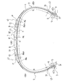
- FIG. 1 is a meridian cross-sectional view showing a pneumatic tire according to an embodiment of the present invention.
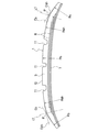
- 2 is an enlarged cross-sectional view of the tread portion of the pneumatic tire of FIG.
- FIG. 1 and 2 show a pneumatic tire for a passenger car according to an embodiment of the present invention.
- the pneumatic tire of the present embodiment includes a tread portion 1 that extends in the tire circumferential direction and has an annular shape, a pair of sidewall portions 2 that are disposed on both sides of the tread portion 1, And a pair of bead portions 3 disposed inside the wall portion 2 in the tire radial direction.
- At least one carcass layer 4 including a plurality of carcass cords extending in the tire radial direction is mounted.
- an organic fiber cord such as nylon or polyester is preferably used.
- An annular bead core 5 is embedded in each bead portion 3, and a bead filler 6 made of a rubber composition is disposed on the outer periphery of the bead core 5.
- the bead filler 6 is disposed on the outer peripheral side of the bead core 5 as necessary to fill the gap between the bead core 5 and the carcass layer 4.
- Such a bead filler 6 may or may not be arranged, but is preferably arranged in order to suppress a failure at the time of manufacture.
- An air permeation preventive layer 7 is provided on the inner surface of the tire along the carcass layer 4. Such an air permeation preventive layer 7 may be embedded inside the tire along the carcass layer 4 or may be provided both on the inner surface of the tire and inside the tire.
- At least one reinforcing layer 8 including a plurality of aligned reinforcing cords is embedded on the outer peripheral side of the carcass layer 4 in the tread portion 1.
- a steel cord can be used, but an organic fiber cord such as aramid, polyolefin ketone (POK), polyethylene terephthalate (PET) is preferably used.
- POK polyolefin ketone
- PET polyethylene terephthalate
- a composite cord (hybrid cord) obtained by combining and twisting different types of organic fibers may be used.
- a tread rubber layer 9 is laminated on the outer peripheral side of the reinforcing layer 8.
- the tread rubber layer 9 may have a single layer structure, but may have a laminated structure of an under tread and a cap tread.
- the tread portion 1 having such a tread rubber layer 9 is formed with a plurality of circumferential grooves 11 extending in the tire circumferential direction and a plurality of lug grooves 12 extending in the tire width direction.
- the tread profile 10 that forms the contour of the tread portion 1 in the tire meridian cross section is located at the center of the tread portion 1 in the tire width direction and has a center arc having a curvature radius Rc, and the tread portion 1.
- a plurality of arcs including a side arc having a curvature radius Rs located on the outermost side in the tire width direction and a shoulder arc having a curvature radius Rsh located on the inner side in the tire width direction of the side arc.
- the shoulder arc is an arc that defines the contour of the tread surface of the land portion located on the outermost side in the tire width direction of the tread portion 1, and the side arc is the side wall surface of the land portion located on the outermost side in the tire width direction of the tread portion 1. It is a circular arc that defines the contour of.
- the center arc and the shoulder arc may be a common arc or may be different arcs.
- Another arc may be interposed between the center arc and the shoulder arc.
- the shoulder arc and the side arc may be connected so as to contact each other, or may be connected so as to cross each other. Another arc may be interposed between the shoulder arc and the side arc in order to smoothly connect the both.
- each sidewall portion 2 has a rim check line 21 extending in the tire circumferential direction on the outer surface of the tire.
- the rim check line 21 is formed to confirm the fitting state of the tire to the rim, and usually has a ridge protruding from the outer surface of the tire.
- the first region A is partitioned between the pair of first boundary lines L1 and L1
- the second region B is partitioned between the first boundary line L1 and the second boundary line L2
- the second boundary line L2 The third region C is also divided on the bead toe 31 side, and the first region A, the second region B, and the third region C have sectional areas (mm 2 ) of SA, SB, and SC, respectively.
- the peripheral lengths (mm) along the tire inner surface of the region B and the third region C are a, b, and c, respectively
- the pneumatic tire has a ratio SA / a, SB / b of 7.5 ⁇ SA / It is configured to satisfy the relationship of a ⁇ 11.5 and 2.0 ⁇ SB / b ⁇ 6.0.
- the pneumatic tire is satisfied by satisfying the relationships of 7.5 ⁇ SA / a ⁇ 11.5 and 2.0 ⁇ SB / b ⁇ 6.0 with respect to the ratios SA / a and SB / b. Since the volume (substantial average thickness) of the first region A and the second region B is minimized, the tire weight is greatly reduced without impairing the tire performance such as wear resistance and cut resistance. Accordingly, the rolling resistance can be greatly reduced.
- the first region A corresponding to the tread portion 1 if the ratio SA / a is smaller than 7.5, the wear resistance is lowered, and conversely if it is larger than 11.5, the lightening effect is insufficient. Become.
- the ratio SC / c should satisfy the relationship of 4.0 ⁇ SC / c ⁇ 8.0. That is, the ratio SC / c may be made as small as possible by reducing the number of wire turns of the bead core 5, reducing the cross-sectional area of the bead filler 6, or reducing the thickness of the rim cushion rubber layer. As a result, the volume of the third region C of the pneumatic tire is suppressed to a necessary minimum, so that the tire weight and rolling resistance can be greatly reduced without impairing the fitting characteristics, particularly the rim detachment resistance.
- the third region C corresponding to the bead portion 3 when the ratio SC / c is smaller than 4.0, the fitting characteristic is deteriorated.
- the cross-sectional area SA of the first region A, the cross-sectional area SB of the second region B, and the cross-sectional area SC of the third region C vary greatly depending on the tire size, but these cross-sectional areas SA, SB, SC are By defining the ratios SA / a, SB / b, and SC / c that are values divided by the peripheral lengths a, b, and c of the respective regions, the above-described effects can be expected regardless of the tire size. it can.
- the ratio STr / a has a relationship of STr / a ⁇ 7.5, more preferably 5.0 ⁇ STr. It is preferable to satisfy the relationship of /a ⁇ 7.0. As a result, the volume (substantial average thickness) in the first region A of the tread rubber layer 9 is suppressed to the minimum necessary, so that the tire weight and rolling resistance are greatly reduced without impairing the wear resistance. can do.
- an air permeation preventive layer 7 is disposed along the carcass layer 4 and / or on the tire inner surface.
- the air permeation coefficient of the air permeation preventive layer 7 is 50 ⁇ 10 ⁇ 12 cc. It is good that it is below cm / cm 2 ⁇ sec ⁇ cmHg.
- the air permeation preventive layer 7 is preferably composed of a thermoplastic resin or a thermoplastic elastomer composition obtained by blending a thermoplastic resin and an elastomer.
- the air permeation preventive layer 7 having a lower air permeation coefficient than the conventional air permeation preventive layer mainly composed of butyl rubber, the air permeation preventive layer 7 can be made thinner and further weight reduction can be achieved.
- the air permeation coefficient of the air permeation preventive layer 7 is larger than 50 ⁇ 10 ⁇ 12 cc ⁇ cm / cm 2 ⁇ sec ⁇ cmHg, it is difficult to further reduce the weight.
- the reinforcing layer 8 is preferably composed of a ply in which a plurality of organic fiber cords are arranged. By using an organic fiber cord for the reinforcing layer 8 disposed in the tread portion 1, further weight reduction can be achieved.
- a circumferential reinforcing layer in which a plurality of reinforcing cords are arranged substantially in parallel along the tire circumferential direction, or a plurality of reinforcing cords are arranged so as to be inclined with respect to the tire circumferential direction.
- An inclined reinforcing layer can be employed, and the two can be used in combination.
- the inclination angle of the reinforcing cord with respect to the tire circumferential direction may be set to 5 ° or less, whereby the tagging effect based on the reinforcing layer 8 can be enhanced.
- the circumferential reinforcing layer has a jointless structure in which at least one reinforcing cord is aligned and rubber-coated strip material is continuously wound in the tire circumferential direction.
- the inclination angle of the reinforcing cord with respect to the tire circumferential direction may be in the range of 20 ° to 50 °, thereby increasing the cornering power without increasing the rolling resistance.
- the cornering power is not increased sufficiently.
- the reinforcing cord is larger than 50 °, the out-of-plane bending rigidity of the reinforcing layer 8 is lowered and rolled. Resistance may increase.
- the ratio S BFL / SC should satisfy the relationship of 0.10 ⁇ S BFL /SC ⁇ 0.30. .
- the cross-sectional area SBFL of the bead filler 5 relatively small in the third region C, further weight reduction can be achieved.
- the ratio S BFL / SC is smaller than 0.10, the rigidity of the bead portion 3 becomes insufficient, and conversely if it is larger than 0.30, the lightening effect is obtained. descend.
- the fineness of the carcass cord of the carcass layer 4 can be selected from the range of, for example, 900 dtex / 2 to 2000 dtex / 2, and the number of drivings per 50 mm width is, for example, in the range of 30 to 70. You can choose from.
- the fineness of the carcass cord of the carcass layer 4 is 900 dtex / 2 to 1400 dtex / 2, and the number of drivings per 50 mm width is preferably 45 to 70. That is, by adopting a thinner carcass cord, the carcass layer 4 can be made thinner and contribute to weight reduction, while the required pressure resistance can be ensured by increasing the number of driven carcass cords.
- the fineness of the carcass cord is smaller than 900 dtex / 2, it is difficult to ensure the pressure resistance, and conversely if it is larger than 1400 dtex / 2, the lightening effect is lowered.
- thermoplastic resin or a thermoplastic elastomer composition obtained by blending an elastomer and a thermoplastic resin constituting the air permeation preventive layer of the pneumatic tire of the present invention will be described.
- thermoplastic resin used in the present invention examples include polyamide resins [for example, nylon 6 (N6), nylon 66 (N66), nylon 46 (N46), nylon 11 (N11), nylon 12 (N12), Nylon 610 (N610), Nylon 612 (N612), Nylon 6/66 copolymer (N6 / 66), Nylon 6/66/610 copolymer (N6 / 66/610), Nylon MXD6 (MXD6), Nylon 6T , Nylon 6 / 6T copolymer, nylon 66 / PP copolymer, nylon 66 / PPS copolymer] and their N-alkoxyalkylated products (for example, methoxymethylated product of nylon 6, nylon 6/610 copolymer) Methoxymethylated product, nylon 612 methoxymethylated product], polyester resin [for example, Ribbylene terephthalate (PBT), polyethylene terephthalate (PET), polyethylene isophthalate (PEI), PET / PE
- Examples of the elastomer used in the present invention include diene rubber and hydrogenated products thereof [for example, natural rubber (NR), isoprene rubber (IR), epoxidized natural rubber, styrene butadiene rubber (SBR), butadiene rubber (BR, high cis BR and low cis BR), nitrile rubber (NBR), hydrogenated NBR, hydrogenated SBR], olefin rubber [for example, ethylene propylene rubber (EPDM, EPM), maleic acid modified ethylene propylene rubber (M- EPM), butyl rubber (IIR), isobutylene and aromatic vinyl or diene monomer copolymer, acrylic rubber (ACM), ionomer], halogen-containing rubber [for example, Br-IIR, CI-IIR, isobutylene paramethylstyrene copolymer Combined bromide (Br-IPMS), chloroprene rubber (C ), Hydrin rubber (CHR), chlorosulf
- compatibility between the specific thermoplastic resin and the elastomer described above is different, they can be made compatible by using an appropriate compatibilizing agent as the third component.
- an appropriate compatibilizing agent By mixing the compatibilizer with the blend system, the interfacial tension between the thermoplastic resin and the elastomer decreases, and as a result, the diameter of the rubber particles forming the dispersed phase becomes finer. It will be expressed effectively.
- a compatibilizing agent generally includes a copolymer having a structure of both or one of a thermoplastic resin and an elastomer, or an epoxy group, a carbonyl group, a halogen group, and an amino group that can react with the thermoplastic resin or elastomer.
- a copolymer having a oxazoline group, a hydroxyl group and the like can be taken.
- These may be selected according to the type of thermoplastic resin and elastomer to be mixed, but those commonly used include styrene / ethylene butylene block copolymer (SEBS) and its maleic acid modified product, EPDM, EPM, EPDM / styrene or EPDM / acrylonitrile graft copolymer and its modified maleic acid, styrene / maleic acid copolymer, reactive phenoxin and the like can be mentioned.
- SEBS styrene / ethylene butylene block copolymer
- the amount of the compatibilizing agent is not particularly limited, but is preferably 0.5 to 10 parts by weight with respect to 100 parts by weight of the polymer component (the total of the thermoplastic resin and the elastomer). *
- the composition ratio between the specific thermoplastic resin and the elastomer is not particularly limited, and is appropriately determined so as to have a structure in which the elastomer is dispersed as a discontinuous phase in the thermoplastic resin matrix.
- the preferred range is 90/10 to 15/85 by weight.
- the thermoplastic resin and the thermoplastic elastomer composition can be mixed with other polymers such as the above-mentioned compatibilizing agent as long as they do not impair the necessary characteristics as the air permeation preventive layer.
- the purpose of mixing other polymers is to improve the compatibility between the thermoplastic resin and the elastomer, to improve the molding processability of the material, to improve the heat resistance, to reduce the cost, etc.
- the material that can be used include polyethylene (PE), polypropylene (PP), polystyrene (PS), ABS, SBS, and polycarbonate (PC).
- fillers (calcium carbonate, titanium oxide, alumina, etc.) generally incorporated into polymer blends, reinforcing agents such as carbon black and white carbon, softeners, plasticizers, processing aids, pigments, dyes, and aging
- reinforcing agents such as carbon black and white carbon, softeners, plasticizers, processing aids, pigments, dyes, and aging
- An inhibitor or the like can be arbitrarily blended as long as necessary characteristics as an air permeation preventive layer are not impaired.
- the elastomer can be dynamically vulcanized when mixed with the thermoplastic resin.
- the vulcanizing agent, vulcanization aid, vulcanization conditions (temperature, time), and the like in the case of dynamic vulcanization may be appropriately determined according to the composition of the elastomer to be added, and are not particularly limited.
- a general rubber vulcanizing agent (crosslinking agent) can be used as the vulcanizing agent.
- sulfur vulcanizing agents include powdered sulfur, precipitated sulfur, highly dispersible sulfur, surface-treated sulfur, insoluble sulfur, dimorpholine disulfide, alkylphenol disulfide, and the like. 4 phr [In the present specification, “phr” refers to parts by weight per 100 parts by weight of the elastomer component. same as below. ] Can be used.
- Organic peroxide vulcanizing agents include benzoyl peroxide, t-butyl hydroperoxide, 2,4-dichlorobenzoyl peroxide, 2,5-dimethyl-2,5-di (t-butyl peroxide). Examples thereof include oxy) hexane, 2,5-dimethylhexane-2,5-di (peroxylbenzoate), and about 1 to 20 phr can be used.
- examples of the phenol resin vulcanizing agent include bromides of alkyl phenol resins, mixed crosslinking systems containing halogen donors such as tin chloride and chloroprene, and alkyl phenol resins. For example, about 1 to 20 phr is used. Can do.
- zinc white about 5 phr
- magnesium oxide about 4 phr
- risurge about 10 to 20 phr
- p-quinonedioxime p-dibenzoylquinonedioxime
- tetrachloro-p-benzoquinone poly-p- Examples include dinitrosobenzene (about 2 to 10 phr) and methylenedianiline (about 0.2 to 10 phr).
- a vulcanization accelerator as needed.
- the vulcanization accelerator include general vulcanization accelerators such as aldehyde / ammonia, guanidine, thiazole, sulfenamide, thiuram, dithioate, and thiourea, such as 0.5 to About 2 phr can be used.
- aldehyde / ammonia vulcanization accelerator hexamethylenetetramine and the like
- guanidinium vulcanization accelerator diphenyl guanidine, etc.
- thiazole vulcanization accelerator dibenzothiazyl disulfide (DM), 2-mercaptobenzothiazole and its Zn salt, cyclohexylamine salt, etc.
- sulfenamide vulcanization accelerators include cyclohexylbenzothiazylsulfenamide (CBS), N-oxydiethylenebenzothiazyl-2-
- thiuram vulcanization accelerators such as sulfenamide, Nt-butyl-2-benzothiazole sulfenamide, and 2- (thymolpolynyldithio) benzothiazole include tetramethylthiuram disulfide (TMTD), tetraethyl Thiuram disulfide (TMTD), te
- a vulcanization accelerating aid general rubber auxiliaries can be used together.
- zinc white (about 5 phr) stearic acid, oleic acid and Zn salts thereof (about 2 to 4 phr) Etc. can be used.
- a method for producing a thermoplastic elastomer composition includes a thermoplastic resin in which a thermoplastic resin and an elastomer (unvulcanized in the case of rubber) are melt-kneaded in advance using a twin-screw kneading extruder or the like to form a continuous phase (matrix). By dispersing the elastomer as a dispersed phase (domain) in it. When the elastomer is vulcanized, a vulcanizing agent may be added under kneading to dynamically vulcanize the elastomer.
- various compounding agents for the thermoplastic resin or elastomer may be added during the kneading, but it is preferable to mix them in advance before kneading.
- the kneading machine used for kneading the thermoplastic resin and the elastomer is not particularly limited, and a screw extruder, a kneader, a Banbury mixer, a biaxial kneading extruder, or the like can be used.
- a twin-screw kneading extruder for kneading the thermoplastic resin and the elastomer and for dynamic vulcanization of the elastomer.
- two or more types of kneaders may be used and kneaded sequentially.
- the temperature may be higher than the temperature at which the thermoplastic resin melts.
- the shear rate during kneading is preferably 1000 to 7500 sec ⁇ 1 .
- the entire kneading time is from 30 seconds to 10 minutes, and when a vulcanizing agent is added, the vulcanization time after addition is preferably from 15 seconds to 5 minutes.
- the polymer composition produced by the above method may be formed into a desired shape by a general thermoplastic resin molding method such as injection molding or extrusion molding.
- thermoplastic elastomer composition thus obtained has a structure in which an elastomer is dispersed as a discontinuous phase in a matrix of a thermoplastic resin.
- the inner liner layer can be provided with sufficient flexibility and sufficient rigidity due to the effect of the resin layer as a continuous phase, and the thermoplastic resin can be molded regardless of the amount of elastomer. The same moldability as can be obtained.
- the Young's modulus in the standard atmosphere of the thermoplastic resin and the thermoplastic elastomer composition as defined by JIS K7100 is not particularly limited, but is preferably 1 to 500 MPa, more preferably 50 to 500 MPa.
- thermoplastic resin or thermoplastic elastomer composition can be formed into a sheet or film and used alone, but an adhesive layer may be laminated in order to enhance the adhesion to the adjacent rubber.
- adhesive polymer constituting the adhesive layer include ultrahigh molecular weight polyethylene (UHMWPE), ethylene ethyl acrylate copolymer (EEA), ethylene methyl acrylate resin (EMA) having a molecular weight of 1 million or more, preferably 3 million or more.
- EAA ethylene acrylic acid copolymer
- PP polypropylene
- PP polypropylene
- PP polypropylene
- PP polypropylene
- PP polypropylene
- PP polypropylene
- PP polypropylene
- PP polypropylene
- PP polypropylene
- PP polypropylene
- PP polypropylene
- PP polypropylene
- PP polypropylene
- PP polypropylene
- PP polypropylene
- PP polypropylene
- PP polypropylene
- PP polypropylene
- PP polypropylene
- PP polypropylene
- PP polypropylene
- PP polypropylene
- PP polypropylene
- PP polypropylene
- PP polypropylene
- PP polypropylene
- PP polypropylene
- PP polypropylene
- PP polypropylene
- PP polypropylene
- a carcass layer is mounted between a pair of bead portions, a bead core is embedded in each bead portion, a bead filler is disposed on the outer peripheral side of each bead core, and on the outer peripheral side of the carcass layer
- a tread rubber layer is laminated on the outer peripheral side of the reinforcing layer, and an air permeation preventing layer is provided on the inner surface of the tire, the pneumatic tire is divided by a first boundary line and a second boundary line.
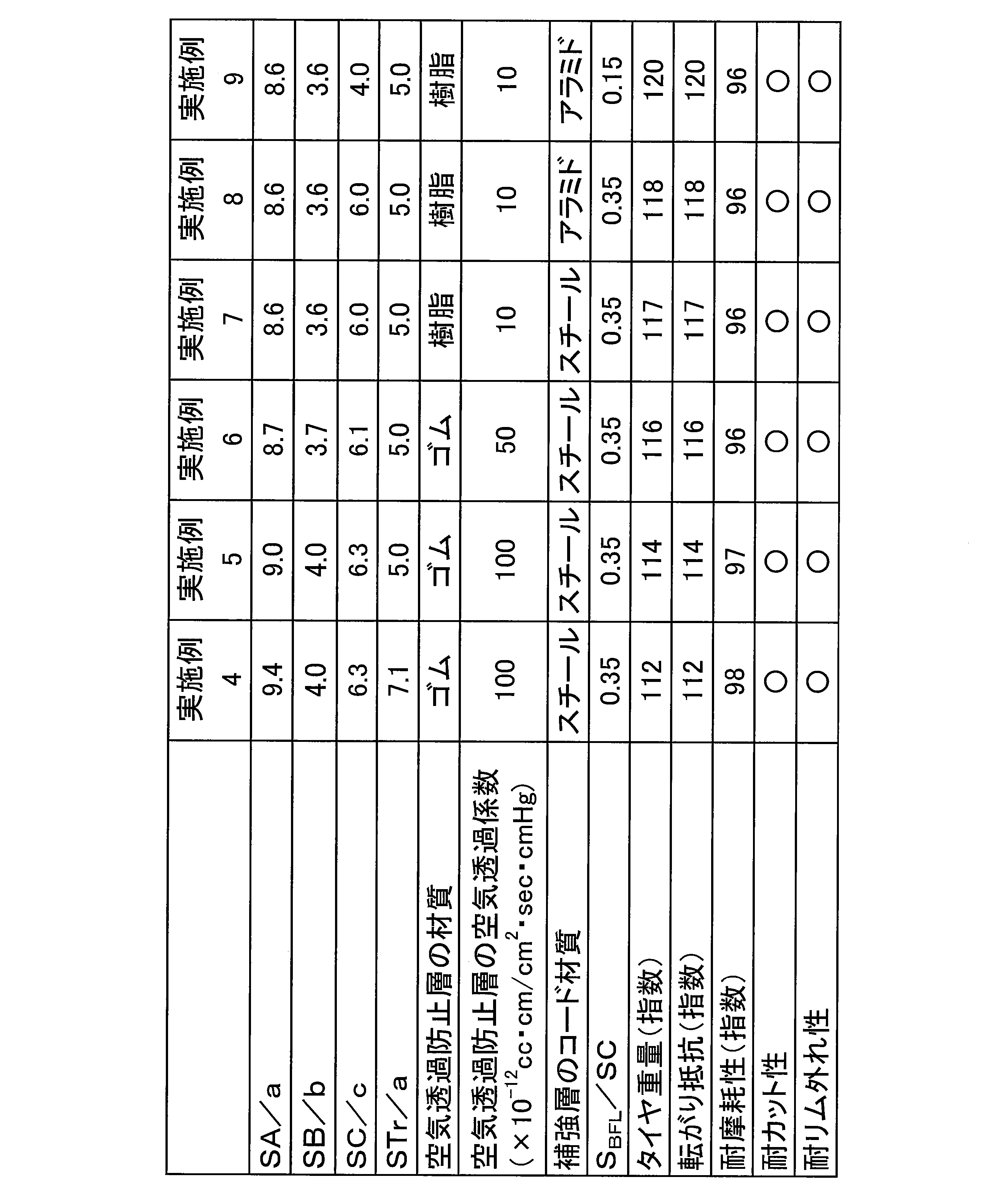
- Table 2 Various different conventional example were as shown in Table 2, it was manufactured tires of Comparative Examples 1-4 and Examples 1-9.
- Tire weight The weight of each test tire was measured. The evaluation results are shown as an index with the conventional example being 100, using the reciprocal of the measured value. A larger index value means lighter weight.
- Rolling resistance Each test tire is mounted on a wheel with a rim size of 15 ⁇ 6J and mounted on a rolling resistance tester equipped with a drum having a radius of 854 mm, and pre-run for 30 minutes under conditions of air pressure 210 kPa, load 4.82 kN, and speed 80 km / h. Then, rolling resistance was measured under the same conditions. The evaluation results are shown as an index with the conventional example being 100, using the reciprocal of the measured value. It means that rolling resistance is so small that this index value is large.
- Abrasion resistance Each test tire was assembled on a wheel with a rim size of 15 ⁇ 6 J and mounted on a test vehicle. After running on a dry road surface of 10,000 km under the conditions of an air pressure of 210 kPa and one passenger, the amount of wear of each tire was measured. The evaluation results are shown as an index with the conventional example being 100, using the reciprocal of the measured value. A larger numerical value means better wear resistance. In addition, if the index value of abrasion resistance is 95 or more, it is a level which is practically satisfactory.
- Cut resistance Each test tire is assembled to a wheel with a rim size of 15 ⁇ 6J and mounted on a test vehicle. The tire is mounted on a curb with a height of 15 cm and an angle of 30 ° at a speed of 10 km / h under conditions of air pressure of 210 kPa, and this is repeated five times. The damage of the sidewall portion was measured. The evaluation results are indicated by “ ⁇ ” when there is no side cut that affects the running, and by “x” when there is a side cut that affects the running.
- Rim detachment resistance Each test tire is mounted on a wheel with a rim size of 15 ⁇ 6J and mounted on a test vehicle.
- the initial air pressure is 210 kPa
- a load of 80% of the JIS normal load is applied
- a circle with a radius of 25 m is applied at a speed of 60 km / h.
- Traveling, the air pressure was lowered by 10 kPa, and the air pressure when the rim was removed was measured.
- the evaluation results are indicated by “ ⁇ ” when there is no rim removal at an air pressure within a range that does not affect running, and by “x” when there is rim removal.
- the tires of Examples 1 to 9 can greatly reduce the tire weight and rolling resistance in comparison with the conventional examples, and further, wear resistance, cut resistance, Tire performance such as rim detachment resistance was not impaired.
Landscapes
- Engineering & Computer Science (AREA)
- Mechanical Engineering (AREA)
- Tires In General (AREA)
Abstract
Description
タイヤ子午線断面において前記トレッド部の輪郭を形成するトレッドプロファイルが、前記トレッド部のタイヤ幅方向の最も外側に位置するサイド円弧と、該サイド円弧のタイヤ幅方向内側に位置するショルダー円弧とを含み、これらサイド円弧の延長線とショルダー円弧の延長線との交点を通りタイヤ内面に対して直交する一対の第一境界線を規定し、各サイドウォール部がタイヤ周方向に延在するリムチェックラインを有し、タイヤ子午線断面において前記リムチェックラインを通りタイヤ内面に対して直交する一対の第二境界線を規定し、前記一対の第一境界線の相互間に第一領域を区分し、前記第一境界線と前記第二境界線との間に第二領域を区分し、前記第二境界線よりもビードトウ側に第三領域を区分し、前記第一領域乃至前記第三領域の断面積(mm2)をそれぞれSA,SB,SCとし、前記第一領域乃至前記第三領域のタイヤ内面に沿ったペリフェリ長さ(mm)をそれぞれa,b,cとしたとき、比SA/a,SB/bについて7.5≦SA/a≦11.5、2.0≦SB/b≦6.0の関係を満足することを特徴とするものである。
各試験タイヤの重量を測定した。評価結果は、測定値の逆数を用い、従来例を100とする指数にて示した。この指数値が大きいほど軽量であることを意味する。
各試験タイヤをリムサイズ15×6Jのホイールに組み付けて半径854mmのドラムを備えた転がり抵抗試験機に装着し、空気圧210kPa、荷重4.82kN、速度80km/hの条件にて30分間の予備走行を行った後、同条件にて転がり抵抗を測定した。評価結果は、測定値の逆数を用い、従来例を100とする指数にて示した。この指数値が大きいほど転がり抵抗が小さいことを意味する。
各試験タイヤをリムサイズ15×6Jのホイールに組み付けて試験車両に装着し、空気圧210kPa、1名乗車の条件で、乾燥路面を10000km走行した後、各タイヤの摩耗量を測定した。評価結果は、測定値の逆数を用い、従来例を100とする指数にて示した。この数値値が大きいほど耐摩耗性が良好であることを意味する。なお、耐摩耗性の指数値は95以上であれば実用上問題ないレベルである。
各試験タイヤをリムサイズ15×6Jのホイールに組み付けて試験車両に装着し、空気圧210kPaの条件で、速度10km/hにて、高さ15cmの縁石に30°の角度で乗り上げ、これを5回繰り返し、サイドウォール部の損傷を測定した。評価結果は、走行に影響を与える程度のサイドカットがない場合を「○」にて示し、走行に影響を与える程度のサイドカットがある場合を「×」にて示した。
各試験タイヤをリムサイズ15×6Jのホイールに組み付けて試験車両に装着し、初期の空気圧を210kPaとし、JIS常用荷重の80%の荷重を負荷して60km/hの速度で半径25mの円上を走行し、空気圧を10kPaずつ下げて行き、リムが外れた時の空気圧を測定した。評価結果は、走行に影響を与えない範囲の空気圧でリム外れがない場合を「○」にて示し、リム外れがある場合を「×」にて示した。

2 サイドウォール部
3 ビード部
4 カーカス層
5 ビードコア
6 ビードフィラー
7 空気透過防止層
8 補強層
9 トレッドゴム層
10 トレッドプロファイル
21 リムチェックライン
P 交点
L1 第一境界線
L2 第二境界線
A 第一領域
B 第二領域
C 第三領域
Claims (7)
- タイヤ周方向に延在して環状をなすトレッド部と、該トレッド部の両側に配置された一対のサイドウォール部と、これらサイドウォール部のタイヤ径方向内側に配置された一対のビード部とを備え、該一対のビード部間に少なくとも1層のカーカス層を装架し、各ビード部にビードコアを埋設し、前記カーカス層の外周側に少なくとも1層の補強層を配置し、該補強層の外周側にトレッドゴム層を積層した空気入りタイヤにおいて、
タイヤ子午線断面において前記トレッド部の輪郭を形成するトレッドプロファイルが、前記トレッド部のタイヤ幅方向の最も外側に位置するサイド円弧と、該サイド円弧のタイヤ幅方向内側に位置するショルダー円弧とを含み、これらサイド円弧の延長線とショルダー円弧の延長線との交点を通りタイヤ内面に対して直交する一対の第一境界線を規定し、各サイドウォール部がタイヤ周方向に延在するリムチェックラインを有し、タイヤ子午線断面において前記リムチェックラインを通りタイヤ内面に対して直交する一対の第二境界線を規定し、前記一対の第一境界線の相互間に第一領域を区分し、前記第一境界線と前記第二境界線との間に第二領域を区分し、前記第二境界線よりもビードトウ側に第三領域を区分し、前記第一領域乃至前記第三領域の断面積(mm2)をそれぞれSA,SB,SCとし、前記第一領域乃至前記第三領域のタイヤ内面に沿ったペリフェリ長さ(mm)をそれぞれa,b,cとしたとき、比SA/a,SB/bについて7.5≦SA/a≦11.5、2.0≦SB/b≦6.0の関係を満足することを特徴とする乗用車用空気入りタイヤ。 - 比SC/cについて4.0≦SC/c≦8.0の関係を満足することを特徴とする請求項1に記載の乗用車用空気入りタイヤ。
- 前記トレッドゴム層の前記第一領域内での断面積をSTrとしたとき、比STr/aについてSTr/a≦7.5の関係を満足することを特徴とする請求項1又は2に記載の乗用車用空気入りタイヤ。
- 前記カーカス層に沿ってタイヤ内部及び/又はタイヤ内面に空気透過係数が50×10-12cc・cm/cm2・sec・cmHg以下の空気透過防止層を設けたことを特徴とする請求項1~3のいずれかに記載の乗用車用空気入りタイヤ。
- 前記空気透過防止層が熱可塑性樹脂又は熱可塑性樹脂とエラストマーとをブレンドした熱可塑性エラストマー組成物から構成されることを特徴とする請求項1~4のいずれかに記載の乗用車用空気入りタイヤ。
- 前記補強層が複数本の有機繊維コードを配列したプライから構成されることを特徴とする請求項1~5のいずれかに記載の乗用車用空気入りタイヤ。
- 前記各ビードコアの外周側にビードフィラーを配置し、該ビードフィラーのタイヤ子午線断面での断面積をSBFLとしたとき、比SBFL/SCについて0.10≦SBFL/SC≦0.30の関係を満足することを特徴とする請求項1~6のいずれかに記載の乗用車用空気入りタイヤ。
Priority Applications (5)
| Application Number | Priority Date | Filing Date | Title |
|---|---|---|---|
| CN201380076850.3A CN105408130B (zh) | 2013-08-12 | 2013-08-12 | 乘用车用充气轮胎 |
| JP2013536733A JP5494894B1 (ja) | 2013-08-12 | 2013-08-12 | 乗用車用空気入りタイヤ |
| PCT/JP2013/071781 WO2015022720A1 (ja) | 2013-08-12 | 2013-08-12 | 乗用車用空気入りタイヤ |
| US14/911,232 US11453250B2 (en) | 2013-08-12 | 2013-08-12 | Pneumatic tire for passenger vehicle |
| DE112013007330.7T DE112013007330B4 (de) | 2013-08-12 | 2013-08-12 | Luftreifen für Personenkraftwagen |
Applications Claiming Priority (1)
| Application Number | Priority Date | Filing Date | Title |
|---|---|---|---|
| PCT/JP2013/071781 WO2015022720A1 (ja) | 2013-08-12 | 2013-08-12 | 乗用車用空気入りタイヤ |
Publications (1)
| Publication Number | Publication Date |
|---|---|
| WO2015022720A1 true WO2015022720A1 (ja) | 2015-02-19 |
Family
ID=50941613
Family Applications (1)
| Application Number | Title | Priority Date | Filing Date |
|---|---|---|---|
| PCT/JP2013/071781 Ceased WO2015022720A1 (ja) | 2013-08-12 | 2013-08-12 | 乗用車用空気入りタイヤ |
Country Status (5)
| Country | Link |
|---|---|
| US (1) | US11453250B2 (ja) |
| JP (1) | JP5494894B1 (ja) |
| CN (1) | CN105408130B (ja) |
| DE (1) | DE112013007330B4 (ja) |
| WO (1) | WO2015022720A1 (ja) |
Cited By (1)
| Publication number | Priority date | Publication date | Assignee | Title |
|---|---|---|---|---|
| CN108688407A (zh) * | 2017-03-30 | 2018-10-23 | 正新橡胶工业股份有限公司 | 无内胎的自行车轮胎结构 |
Families Citing this family (5)
| Publication number | Priority date | Publication date | Assignee | Title |
|---|---|---|---|---|
| EP3153331B1 (en) * | 2014-06-06 | 2019-08-28 | Bridgestone Corporation | Pneumatic tire |
| US20160288575A1 (en) * | 2015-03-31 | 2016-10-06 | The Goodyear Tire & Rubber Company | Pneumatic tire and method for making a pneumatic tire |
| JP6827880B2 (ja) * | 2017-05-11 | 2021-02-10 | 株式会社ブリヂストン | 非空気入りタイヤ |
| CN111356597B (zh) * | 2017-11-20 | 2022-05-24 | 横滨橡胶株式会社 | 充气轮胎 |
| JP7287444B1 (ja) * | 2021-12-17 | 2023-06-06 | 横浜ゴム株式会社 | 空気入りタイヤ |
Citations (15)
| Publication number | Priority date | Publication date | Assignee | Title |
|---|---|---|---|---|
| JPS60234008A (ja) * | 1984-05-06 | 1985-11-20 | Sumitomo Rubber Ind Ltd | 低圧用タイヤ |
| JPH01145202A (ja) * | 1987-11-30 | 1989-06-07 | Sumitomo Rubber Ind Ltd | 空気入りタイヤ |
| JPH04221208A (ja) * | 1990-12-21 | 1992-08-11 | Yokohama Rubber Co Ltd:The | 空気入りタイヤ |
| JPH05162506A (ja) * | 1991-12-12 | 1993-06-29 | Bridgestone Corp | スペアタイヤ |
| JPH05254308A (ja) * | 1992-03-11 | 1993-10-05 | Bridgestone Corp | 空気入りラジアルタイヤ |
| JPH08259741A (ja) * | 1995-01-23 | 1996-10-08 | Yokohama Rubber Co Ltd:The | タイヤ用ポリマー組成物およびそれを使用した空気入りタイヤ |
| WO2003082609A1 (fr) * | 2002-03-29 | 2003-10-09 | Sumitomo Rubber Industries, Ltd. | Pneumatique |
| JP2006327468A (ja) * | 2005-05-27 | 2006-12-07 | Yokohama Rubber Co Ltd:The | 空気入りタイヤ |
| JP2010120479A (ja) * | 2008-11-18 | 2010-06-03 | Yokohama Rubber Co Ltd:The | 空気入りタイヤ |
| WO2010095688A1 (ja) * | 2009-02-18 | 2010-08-26 | 株式会社ブリヂストン | タイヤ |
| JP2011005946A (ja) * | 2009-06-25 | 2011-01-13 | Bridgestone Corp | 空気入りタイヤ |
| JP2011183993A (ja) * | 2010-03-10 | 2011-09-22 | Bridgestone Corp | 空気入りタイヤ |
| JP2012176694A (ja) * | 2011-02-25 | 2012-09-13 | Bridgestone Corp | 空気入りラジアルタイヤ |
| WO2012176372A1 (ja) * | 2011-06-20 | 2012-12-27 | 株式会社ブリヂストン | 空気入りタイヤ |
| JP2013132989A (ja) * | 2011-12-26 | 2013-07-08 | Bridgestone Corp | ランフラットタイヤ |
Family Cites Families (9)
| Publication number | Priority date | Publication date | Assignee | Title |
|---|---|---|---|---|
| JP3131795B2 (ja) | 1992-01-22 | 2001-02-05 | 横浜ゴム株式会社 | 空気入りタイヤ |
| JPH05345506A (ja) | 1992-06-16 | 1993-12-27 | Bridgestone Corp | 空気入りラジアルタイヤ |
| US6079465A (en) * | 1995-01-23 | 2000-06-27 | The Yokohama Rubber Co., Ltd. | Polymer composition for tire and pneumatic tire using same |
| JPH1086606A (ja) * | 1996-09-19 | 1998-04-07 | Bridgestone Corp | 空気入りラジアルタイヤ |
| JP3410636B2 (ja) * | 1997-07-11 | 2003-05-26 | 住友ゴム工業株式会社 | 空気入りタイヤ |
| JP3389500B2 (ja) * | 1998-05-08 | 2003-03-24 | 住友ゴム工業株式会社 | 空気入りタイヤ |
| US6527025B1 (en) * | 1998-09-11 | 2003-03-04 | Sumitomo Rubber Industries, Ltd. | Tubeless tire |
| US6617383B2 (en) * | 2000-04-11 | 2003-09-09 | The Yokohama Rubber Co., Ltd. | Thermoplastic elastomer composition having improved processability and tire using the same |
| JP4534725B2 (ja) | 2004-11-05 | 2010-09-01 | 横浜ゴム株式会社 | 空気入りタイヤ |
-
2013
- 2013-08-12 DE DE112013007330.7T patent/DE112013007330B4/de active Active
- 2013-08-12 JP JP2013536733A patent/JP5494894B1/ja active Active
- 2013-08-12 WO PCT/JP2013/071781 patent/WO2015022720A1/ja not_active Ceased
- 2013-08-12 US US14/911,232 patent/US11453250B2/en active Active
- 2013-08-12 CN CN201380076850.3A patent/CN105408130B/zh active Active
Patent Citations (15)
| Publication number | Priority date | Publication date | Assignee | Title |
|---|---|---|---|---|
| JPS60234008A (ja) * | 1984-05-06 | 1985-11-20 | Sumitomo Rubber Ind Ltd | 低圧用タイヤ |
| JPH01145202A (ja) * | 1987-11-30 | 1989-06-07 | Sumitomo Rubber Ind Ltd | 空気入りタイヤ |
| JPH04221208A (ja) * | 1990-12-21 | 1992-08-11 | Yokohama Rubber Co Ltd:The | 空気入りタイヤ |
| JPH05162506A (ja) * | 1991-12-12 | 1993-06-29 | Bridgestone Corp | スペアタイヤ |
| JPH05254308A (ja) * | 1992-03-11 | 1993-10-05 | Bridgestone Corp | 空気入りラジアルタイヤ |
| JPH08259741A (ja) * | 1995-01-23 | 1996-10-08 | Yokohama Rubber Co Ltd:The | タイヤ用ポリマー組成物およびそれを使用した空気入りタイヤ |
| WO2003082609A1 (fr) * | 2002-03-29 | 2003-10-09 | Sumitomo Rubber Industries, Ltd. | Pneumatique |
| JP2006327468A (ja) * | 2005-05-27 | 2006-12-07 | Yokohama Rubber Co Ltd:The | 空気入りタイヤ |
| JP2010120479A (ja) * | 2008-11-18 | 2010-06-03 | Yokohama Rubber Co Ltd:The | 空気入りタイヤ |
| WO2010095688A1 (ja) * | 2009-02-18 | 2010-08-26 | 株式会社ブリヂストン | タイヤ |
| JP2011005946A (ja) * | 2009-06-25 | 2011-01-13 | Bridgestone Corp | 空気入りタイヤ |
| JP2011183993A (ja) * | 2010-03-10 | 2011-09-22 | Bridgestone Corp | 空気入りタイヤ |
| JP2012176694A (ja) * | 2011-02-25 | 2012-09-13 | Bridgestone Corp | 空気入りラジアルタイヤ |
| WO2012176372A1 (ja) * | 2011-06-20 | 2012-12-27 | 株式会社ブリヂストン | 空気入りタイヤ |
| JP2013132989A (ja) * | 2011-12-26 | 2013-07-08 | Bridgestone Corp | ランフラットタイヤ |
Cited By (2)
| Publication number | Priority date | Publication date | Assignee | Title |
|---|---|---|---|---|
| CN108688407A (zh) * | 2017-03-30 | 2018-10-23 | 正新橡胶工业股份有限公司 | 无内胎的自行车轮胎结构 |
| CN108688407B (zh) * | 2017-03-30 | 2021-01-29 | 正新橡胶工业股份有限公司 | 无内胎的自行车轮胎结构 |
Also Published As
| Publication number | Publication date |
|---|---|
| JP5494894B1 (ja) | 2014-05-21 |
| DE112013007330T5 (de) | 2016-05-25 |
| CN105408130A (zh) | 2016-03-16 |
| US11453250B2 (en) | 2022-09-27 |
| US20160176241A1 (en) | 2016-06-23 |
| JPWO2015022720A1 (ja) | 2017-03-02 |
| DE112013007330B4 (de) | 2020-01-23 |
| CN105408130B (zh) | 2017-10-20 |
Similar Documents
| Publication | Publication Date | Title |
|---|---|---|
| JP4442700B2 (ja) | 空気入りタイヤ及びその製造方法 | |
| JP3695840B2 (ja) | 空気入りタイヤ | |
| JP6236977B2 (ja) | 乗用車用空気入りタイヤ | |
| JP2010264956A (ja) | 空気入りタイヤ及びその製造方法 | |
| JPH1035232A (ja) | 空気入りタイヤ | |
| JP5494894B1 (ja) | 乗用車用空気入りタイヤ | |
| CN106232382B (zh) | 充气轮胎 | |
| JP6418339B1 (ja) | 空気入りタイヤ | |
| JP5928525B2 (ja) | 空気入りタイヤ | |
| JP6152741B2 (ja) | 乗用車用空気入りタイヤ | |
| JPH11189009A (ja) | 空気入りタイヤ | |
| JP6241125B2 (ja) | 乗用車用空気入りタイヤ | |
| JPH11180110A (ja) | 空気入りタイヤ | |
| JP6331685B2 (ja) | 空気入りタイヤ | |
| JP6236978B2 (ja) | 乗用車用空気入りタイヤ | |
| JP6428145B2 (ja) | 空気入りタイヤ | |
| JPH10236115A (ja) | 空気入りタイヤ | |
| JP4710480B2 (ja) | 空気入りタイヤ | |
| JP2009208734A (ja) | 空気入りタイヤ | |
| JP2010167985A (ja) | 空気入りタイヤ | |
| JP2001047811A (ja) | 空気入りタイヤ |
Legal Events
| Date | Code | Title | Description |
|---|---|---|---|
| ENP | Entry into the national phase |
Ref document number: 2013536733 Country of ref document: JP Kind code of ref document: A |
|
| WWE | Wipo information: entry into national phase |
Ref document number: 201380076850.3 Country of ref document: CN |
|
| 121 | Ep: the epo has been informed by wipo that ep was designated in this application |
Ref document number: 13891473 Country of ref document: EP Kind code of ref document: A1 |
|
| WWE | Wipo information: entry into national phase |
Ref document number: 14911232 Country of ref document: US |
|
| WWE | Wipo information: entry into national phase |
Ref document number: 1120130073307 Country of ref document: DE Ref document number: 112013007330 Country of ref document: DE |
|
| 122 | Ep: pct application non-entry in european phase |
Ref document number: 13891473 Country of ref document: EP Kind code of ref document: A1 |