WO2015019960A1 - 可視光反射材用アルミニウム箔とその製造方法 - Google Patents
可視光反射材用アルミニウム箔とその製造方法 Download PDFInfo
- Publication number
- WO2015019960A1 WO2015019960A1 PCT/JP2014/070347 JP2014070347W WO2015019960A1 WO 2015019960 A1 WO2015019960 A1 WO 2015019960A1 JP 2014070347 W JP2014070347 W JP 2014070347W WO 2015019960 A1 WO2015019960 A1 WO 2015019960A1
- Authority
- WO
- WIPO (PCT)
- Prior art keywords
- aluminum foil
- less
- rolling
- surface roughness
- aluminum
- Prior art date
- Legal status (The legal status is an assumption and is not a legal conclusion. Google has not performed a legal analysis and makes no representation as to the accuracy of the status listed.)
- Ceased
Links
Classifications
-
- C—CHEMISTRY; METALLURGY
- C22—METALLURGY; FERROUS OR NON-FERROUS ALLOYS; TREATMENT OF ALLOYS OR NON-FERROUS METALS
- C22C—ALLOYS
- C22C21/00—Alloys based on aluminium
-
- B—PERFORMING OPERATIONS; TRANSPORTING
- B21—MECHANICAL METAL-WORKING WITHOUT ESSENTIALLY REMOVING MATERIAL; PUNCHING METAL
- B21B—ROLLING OF METAL
- B21B1/00—Metal-rolling methods or mills for making semi-finished products of solid or profiled cross-section; Sequence of operations in milling trains; Layout of rolling-mill plant, e.g. grouping of stands; Succession of passes or of sectional pass alternations
- B21B1/40—Metal-rolling methods or mills for making semi-finished products of solid or profiled cross-section; Sequence of operations in milling trains; Layout of rolling-mill plant, e.g. grouping of stands; Succession of passes or of sectional pass alternations for rolling foils which present special problems, e.g. because of thinness
-
- B—PERFORMING OPERATIONS; TRANSPORTING
- B21—MECHANICAL METAL-WORKING WITHOUT ESSENTIALLY REMOVING MATERIAL; PUNCHING METAL
- B21B—ROLLING OF METAL
- B21B3/00—Rolling materials of special alloys so far as the composition of the alloy requires or permits special rolling methods or sequences ; Rolling of aluminium, copper, zinc or other non-ferrous metals
-
- C—CHEMISTRY; METALLURGY
- C22—METALLURGY; FERROUS OR NON-FERROUS ALLOYS; TREATMENT OF ALLOYS OR NON-FERROUS METALS
- C22C—ALLOYS
- C22C21/00—Alloys based on aluminium
- C22C21/06—Alloys based on aluminium with magnesium as the next major constituent
-
- C—CHEMISTRY; METALLURGY
- C22—METALLURGY; FERROUS OR NON-FERROUS ALLOYS; TREATMENT OF ALLOYS OR NON-FERROUS METALS
- C22C—ALLOYS
- C22C21/00—Alloys based on aluminium
- C22C21/06—Alloys based on aluminium with magnesium as the next major constituent
- C22C21/08—Alloys based on aluminium with magnesium as the next major constituent with silicon
-
- B—PERFORMING OPERATIONS; TRANSPORTING
- B21—MECHANICAL METAL-WORKING WITHOUT ESSENTIALLY REMOVING MATERIAL; PUNCHING METAL
- B21B—ROLLING OF METAL
- B21B3/00—Rolling materials of special alloys so far as the composition of the alloy requires or permits special rolling methods or sequences ; Rolling of aluminium, copper, zinc or other non-ferrous metals
- B21B2003/001—Aluminium or its alloys
-
- B—PERFORMING OPERATIONS; TRANSPORTING
- B21—MECHANICAL METAL-WORKING WITHOUT ESSENTIALLY REMOVING MATERIAL; PUNCHING METAL
- B21B—ROLLING OF METAL
- B21B2261/00—Product parameters
- B21B2261/14—Roughness
-
- B—PERFORMING OPERATIONS; TRANSPORTING
- B21—MECHANICAL METAL-WORKING WITHOUT ESSENTIALLY REMOVING MATERIAL; PUNCHING METAL
- B21B—ROLLING OF METAL
- B21B2265/00—Forming parameters
- B21B2265/14—Reduction rate
-
- B—PERFORMING OPERATIONS; TRANSPORTING
- B21—MECHANICAL METAL-WORKING WITHOUT ESSENTIALLY REMOVING MATERIAL; PUNCHING METAL
- B21B—ROLLING OF METAL
- B21B2267/00—Roll parameters
- B21B2267/10—Roughness of roll surface
-
- B—PERFORMING OPERATIONS; TRANSPORTING
- B21—MECHANICAL METAL-WORKING WITHOUT ESSENTIALLY REMOVING MATERIAL; PUNCHING METAL
- B21B—ROLLING OF METAL
- B21B27/00—Rolls, roll alloys or roll fabrication; Lubricating, cooling or heating rolls while in use
- B21B27/02—Shape or construction of rolls
- B21B27/021—Rolls for sheets or strips
Definitions
- the present invention relates to an aluminum foil for a visible light reflecting material and a method for producing the same.
- the term “aluminum foil” is used to include not only pure aluminum foil but also aluminum alloy foil.
- the reflective material used reflects the electromagnetic wave called light with minimal loss, and at the same time, in order to transmit and collect the reflected electromagnetic wave without waste to a predetermined location, the electromagnetic wave is not scattered as much as possible. It is desired to reflect. That is, an important performance required for the reflecting material is that regular reflection of reflecting an electromagnetic wave at the same angle as the incident angle to the reflecting material is performed with a minimum energy loss.
- the degree of regular reflection is evaluated by the numerical value defined by the glossiness (JIS Z 8740).
- the glossiness is evaluated based on the amount of light received from one direction by receiving light incident at a specific angle ⁇ , for example, 60 °, and receiving light reflected at a specific angle ⁇ , for example, 60 °.
- Examples of the reflective material having a high degree of regular reflection and a high reflectance in the visible light region include silver and aluminum.
- aluminum is attracting attention as an application of a visible light reflecting material as a material having a small density, light weight, good thermal conductivity, and relatively inexpensive among metals and having a high reflectance.
- the glossiness is generally about 60 to 70% as the reflection characteristic of the aluminum foil.
- Patent Document 2 Japanese Patent Laid-Open No. 2002-143904 (hereinafter referred to as Patent Document 2), as a method for producing a high-gloss aluminum plate, the aluminum plate is subjected to final finish cooling by a rolling roll surface-finished by film polishing or kiss roll polishing. It is described that it is rolled. Using this method, an aluminum plate having a surface roughness Ra of about 0.20 to 0.60 ⁇ m is obtained by transferring the low surface roughness of the polished roll onto the surface of the aluminum plate.
- Patent Document 2 Japanese Patent Laid-Open No. 2002-143904
- glossiness is generally about 60 to 70% as a reflection characteristic of an aluminum foil.
- the glossiness is 82.2 at the maximum. % Aluminum foil can be obtained. An aluminum foil having such a gloss level cannot meet the application of a reflector having a higher reflectance.
- an object of the present invention is to provide an aluminum foil for visible light reflecting material having higher gloss and a method for producing the same.
- the inventors of the present invention have found that the glossiness of the aluminum foil is improved by controlling not only the surface roughness but also the crystallized matter present on the surface of the aluminum foil. I found it. That is, the aluminum foil for visible light reflector of the present invention and the manufacturing method thereof have the following characteristics.
- the ratio of the total surface area of the crystallized substances existing in a predetermined surface area is 2% or less, and the average surface area per one of the above crystallized substances is
- the surface roughness Rz in the direction perpendicular to the rolling direction is 2 nm or less, and the surface roughness Ra is 10 nm or less.
- the thickness of the aluminum foil is preferably 4 ⁇ m or more and 200 ⁇ m or less.
- the aluminum foil is subjected to final finish cold rolling using a rolling roll having a surface roughness Ra of 40 nm or less under a condition of a reduction rate of 35% or more.
- the aluminum foil for visible light reflecting material of the present invention having the above characteristics has higher gloss than the conventional one, when the aluminum foil for visible light reflecting material of the present invention is applied to the reflecting material, light energy loss is reduced. Light can be transmitted with further reduction.
- the ratio of the total surface area of the crystallized substances existing in the predetermined surface area of the aluminum foil is 2% or less, the average surface area per crystallized substance is 2 ⁇ m 2 or less,
- the surface roughness Rz in the direction perpendicular to the rolling direction, that is, the TD direction is 40 nm or less, and the surface roughness Ra is 10 nm or less.
- the aluminum foil of the present invention has the above-described configuration, so that the glossiness that is an index of regular reflection can exceed 82.2%.
- the crystallized substance refers to various intermetallic compounds such as Al—Fe, Al—Fe—Mn, Al—Mg—Si, and Al—Mn.
- the reflectance of the electromagnetic wave incident on the surface of the crystallized substance is lower than the reflectance of the electromagnetic wave incident on the surface of aluminum itself.
- the surface of the aluminum foil as used in the field of this invention means the area
- the ratio of the total surface area of the crystallized substance to the surface area of the aluminum foil exceeds 2%, the reflectivity of the aluminum foil is lowered when the crystallized substance is present on the surface of the aluminum foil.
- the average surface area per crystallized substance is larger than 2 ⁇ m 2 , the reflectance of the surface of the aluminum foil is uneven.
- the lower limit of the ratio of the total surface area of the crystallized substance existing in the predetermined surface area of the aluminum foil is ideally (theoretical) 0%.
- the lower limit of the average surface area per crystallized substance it is 0.01%.
- the detection limit value of the surface area of the crystallized substance is about 0.01 ⁇ m 2
- the lower limit value of the average surface area per crystallized substance is 0.01 ⁇ m. 2 .
- the crystallized substance existing on the surface of the aluminum foil not only lowers the original reflectance of the aluminum foil but also causes irregularities on the surface of the aluminum foil.
- cold rolling which is one of the processes for producing an aluminum foil
- the crystallized material is harder than the aluminum base, so that aluminum preferentially undergoes plastic deformation.
- the crystallized material rolls on the surface of the aluminum foil that is plastically deformed, and a part of the crystallized material is missing from the surface of the aluminum foil to cause unevenness on the surface of the aluminum foil. For this reason, when the total surface area of the crystallized substance is large, that is, when the amount of the crystallized substance is large, the degree of occurrence of unevenness on the surface of the aluminum foil increases.
- the recess formed when the crystallized substance is missing from the surface of the aluminum foil becomes large.
- the visible light incident on the surface of the aluminum foil is irregularly reflected at the concavo-convex portions formed on the surface of the aluminum foil, so that the reflectance is lowered.
- the surface roughness Rz in the TD direction perpendicular to the rolling direction is 40 nm or less, and the surface roughness Ra is 10 nm or less, whereby the surface roughness of the aluminum foil is reduced. Therefore, it can be suppressed that the visible light reflected by the uneven portion on the surface of the aluminum foil again hits another uneven portion and the reflected light is attenuated.
- aluminum foil is manufactured by cold rolling.
- This cold rolling is applied to the aluminum foil, there are transfer rolls on the surface of the aluminum foil.
- the transfer streaks of the rolling roll cause unevenness on the surface of the aluminum foil. Concavities and convexities made of transfer streaks of a certain size or more cause anisotropy in the reflection angle of visible light. For this reason, the reflectance decreases particularly at a wavelength close to the ultraviolet region, for example, a wavelength of 380 to 600 nm.
- the surface roughness resulting from the transfer lines of the rolling roll can be evaluated as a value of the surface roughness Rz in the direction perpendicular to the rolling direction, that is, in the TD direction.
- the reflectance of light in the visible light region (for example, wavelength of 380 to 600 nm) close to the ultraviolet region is increased, and visible light It can have a high reflectivity over the entire area. Thereby, the average reflectance of the visible light area
- the surface roughness Ra is controlled to 10 nm or less.
- polishing processing such as physical polishing, electrolytic polishing, chemical polishing, or cold rolling using a rolling roll whose surface is in a mirror surface state, etc. is there. Cold rolling using a rolling roll whose surface is in a mirror surface will be described later.
- the thickness of the aluminum foil of the present invention is preferably 4 ⁇ m or more and 200 ⁇ m or less.
- the thickness of the aluminum foil is less than 4 ⁇ m, the mechanical strength cannot be maintained as the aluminum foil, and the surface of the aluminum foil is wrinkled by handling during production.
- the thickness of the aluminum foil exceeds 200 ⁇ m, not only the weight of the aluminum foil increases, but also processing such as molding is restricted, which is not preferable.
- the thickness of the aluminum foil is not less than 6 ⁇ m and not more than 200 ⁇ m. In order to make the thickness of the aluminum foil within the above range, casting and rolling may be performed according to a general aluminum foil manufacturing method.
- an ingot is produced by preparing a molten aluminum having a predetermined composition and solidifying the molten aluminum.
- the obtained ingot may be subjected to a homogenization treatment at a temperature of about 400 to 630 ° C. for about 1 to 20 hours. Thereafter, the ingot is hot rolled and cold rolled until it becomes an aluminum foil having a predetermined thickness.
- the aluminum foil of desired thickness can also be obtained directly by cold rolling after continuous casting.
- the final finish cold rolling step it is preferable to perform rolling at a rolling reduction of 35% or more using a rolling roll having a surface roughness Ra of 40 nm or less.
- the reason for using a rolling roll having a surface roughness Ra of 40 nm or less in the final finish cold rolling process is as follows.
- the surface roughness of the rolling roll used in the final finish cold rolling process greatly affects the surface roughness of the aluminum foil obtained after the final finish cold rolling process.
- the obtained aluminum foil has a surface roughness Rz in the TD direction perpendicular to the rolling direction of more than 40 nm, and the surface roughness Ra Becomes larger than 10 nm.
- the surface roughness Ra of the rolling roll used in the final finish cold rolling step is preferably as small as possible, more preferably 30 nm or less.
- the surface roughness Ra of the rolling roll is the centerline average roughness Ra defined in JIS B0601 (1982 edition), while the surface roughness Ra of the aluminum foil is defined in JIS B0601 (1982 edition). This is a value calculated by extending the centerline average roughness Ra in three dimensions so that it can be applied to the surface.
- the reason why the rolling reduction in the final finish cold rolling process is 35% or more is as follows. Generally, when the rolling reduction decreases, the amount of rolling oil film that is caught between the rolling roll and the aluminum foil tends to increase. For this reason, the number of oil pits having a depth of several to several tens of ⁇ m that is formed by the rolling oil being pushed into the surface of the aluminum foil after the rolling process is increased. As a result, unevenness due to oil pits increases on the surface of the obtained aluminum foil. Therefore, when rolling is performed at a reduction rate of less than 35%, the surface roughness Ra of the resulting aluminum foil is greatly affected by the unevenness caused by the oil pits and becomes larger than 10 nm.
- the upper limit of the rolling reduction is not particularly limited, but is preferably 60% in consideration of rolling properties.
- the aluminum foil When producing a soft aluminum foil, the aluminum foil may be heat-treated at a temperature of about 250 to 450 ° C. for about 1 to 30 hours.
- the surface of the obtained aluminum foil for visible light reflecting material may be further polished so as to improve the glossiness.
- a surface protective layer may be provided on the surface of the aluminum foil for the purpose of protecting the surface.
- the surface protective layer is formed by laminating a film on the surface of an aluminum foil, coating a resin, etc., for example, forming an SiO-based inorganic layer by ion plasma treatment, performing ion plating treatment, sputtering It may be provided on the surface of the aluminum foil by performing a treatment, performing a vapor deposition treatment, performing a plating treatment, or forming an oxide film layer by anodic oxidation.
- the obtained aluminum foil for visible light reflecting material may be formed into an arbitrary shape and used. Specifically, it may be processed into an arbitrary shape by an overhang forming process or a deep drawing process, or may be processed into a shape according to the purpose by a bending process or a bending process.
- One surface of the obtained aluminum foil for visible light reflecting material may be used as a reflecting material, and the other surface may be attached to other parts and used, or bonded to a metal or resin plate or film. May be used. Furthermore, for example, after bonding the surface of an aluminum foil to a resin film, a resist layer may be selectively provided on the surface, and an etching process may be performed to form a wiring pattern for use.
- the composition of the aluminum foil of the present invention is not particularly limited, but the iron (Fe) content is preferably 0.001% by mass to 0.5% by mass. Since iron has a low solid solubility in aluminum, intermetallic compounds such as FeAl 3 are easily crystallized during the casting of aluminum. These crystallized substances have a lower reflectance in the visible light region than the aluminum base, and cause a decrease in the visible light reflectance as the aluminum foil.
- the iron content is 0.5% by mass or more, when all of the added iron is crystallized, the crystallization amount of FeAl 3 as the Al—Fe intermetallic compound exceeds 1.2% by mass. Will be present and the gloss will be lower than 82.2%. For this reason, it is necessary to make iron content into 0.5 mass% or less. Moreover, the intensity
- the content of manganese (Mn) is preferably 0.5% by mass or less.
- manganese has a low solid solubility in aluminum, so that Al—Fe—Mn compounds and the like are easily crystallized during the casting of aluminum.
- the Al-Fe-Mn crystallized material is finer than the Al-Fe based crystallized material, but these crystallized materials have a lower reflectance in the visible light region than the aluminum base, and are used as an aluminum foil. This causes a decrease in the visible light reflectance.
- the manganese content is 0.5 mass% or more, when all of the added manganese is crystallized, the Al-Fe-Mn intermetallic compound is present in an amount exceeding 1.5 mass%, The gloss level is lower than 82.2%. For this reason, it is necessary to make manganese content into 0.5 mass% or less.
- the content of silicon (Si) is preferably 0.001% by mass or more and 0.3% by mass or less. Since silicon has a high solid solubility in aluminum and hardly forms a crystallized substance, the reflectivity in the visible light region is not lowered if the content is such that no crystallized substance is generated in the aluminum foil.
- the mechanical strength of the aluminum foil can be improved by solid solution strengthening, so that the thin foil can be easily rolled. If the silicon content is less than 0.001% by mass, the above-described effects cannot be obtained sufficiently. If the silicon content exceeds 0.3% by mass, coarse crystals are likely to be generated, and not only the reflection characteristics are deteriorated, but also the effect of refining crystal grains is impaired, so that the strength and workability are also improved. It tends to decrease.
- the content of magnesium (Mg) is preferably 3% by mass or less.
- Magnesium has a maximum solid solubility in aluminum of 18% by mass and the occurrence of crystallized substances is extremely small, so the mechanical strength of the aluminum foil should be improved without greatly affecting the reflective properties of the aluminum foil. Can do.
- the magnesium content exceeds 3% by mass, the mechanical strength of the aluminum foil becomes too high, so that the rollability of the aluminum foil is lowered.
- the magnesium content is more preferably 2% by mass or less.
- the aluminum foil of the present invention has a content that does not affect the above characteristics and effects, and includes copper (Cu), zinc (Zn), titanium (Ti), vanadium (V), nickel (Ni), Elements such as chromium (Cr), zirconium (Zr), boron (B), gallium (Ga), and bismuth (Bi) may be included.
- the aluminum foil of the present invention is literally a “foil” and has the following various merits, unlike an “aluminum plate” having a thickness of about 500 ⁇ m or more. That is, the aluminum foil has advantages in that it is particularly excellent in weight reduction and is easy to mold, and exhibits shape followability and flexibility such as sticking to a curved object, which is difficult with an aluminum plate. Moreover, it has the merit with respect to an aluminum plate also in terms of the load with respect to an environment, such as leading to the reduction of waste.
- such an aluminum foil of the present invention makes use of the above-mentioned merits, reflecting a reflector for lighting equipment, a reflector for lighting such as a house, a strobe reflector, and a solar cooker (reflector for cooking utensils by collecting sunlight). It can be suitably used for applications such as packaging materials and decorative materials.
- samples of aluminum foils of Examples and Comparative Examples of the present invention were prepared.
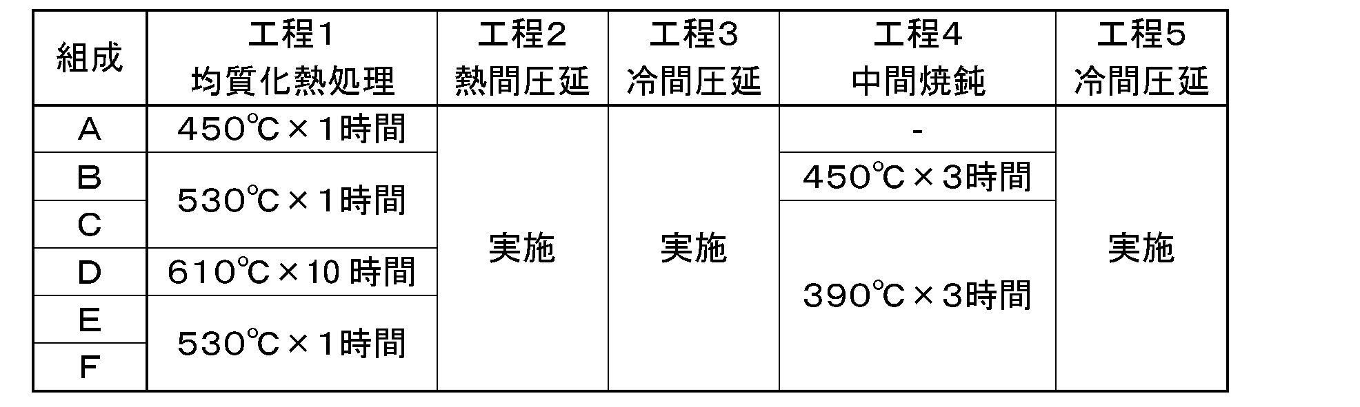
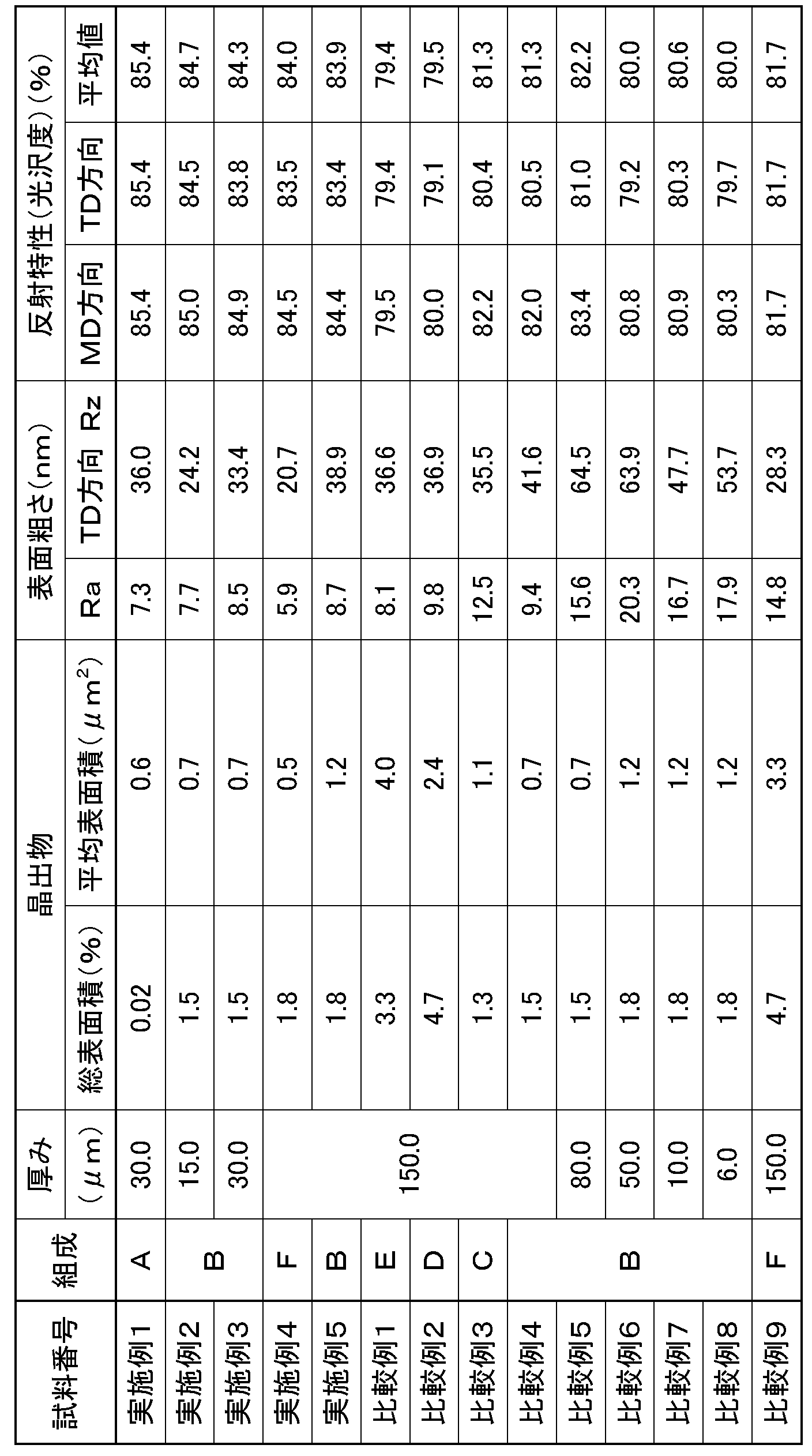
- samples of aluminum foils of Examples 1 to 5 and Comparative Examples 1 to 9 shown in Table 3 were prepared according to the manufacturing process shown in Table 2.
- other element meter indicates the total content of inevitable impurity elements (B, Bi, Pb, Na, etc.) other than the elements specified by JIS.
- an ingot of aluminum obtained by DC casting was subjected to homogenization heat treatment at a predetermined temperature and time in a heating furnace. Thereafter, hot rolling was performed until the thickness became about 6.5 mm. Using the obtained hot rolled material, cold rolling is performed a plurality of times, intermediate annealing is performed at a predetermined temperature and time during the cold rolling, and cold rolling is performed until the thickness reaches a predetermined value. Samples of aluminum foil having thicknesses shown in Table 3 were prepared. At this time, in Examples 1 to 5 and Comparative Examples 1 to 4 and 9, rolling was performed at a rolling reduction of 35% using a rolling roll having a surface roughness Ra of 40 nm in the final finish cold rolling.
- the homogenization heat treatment time may be within a general treatment time, and is not limited to the time shown in Table 2.
- the intermediate annealing conditions are not limited to the temperatures and times shown in Table 2, and may be within the range of general operating conditions.
- the surface state was observed with an optical microscope, and the surface area of the crystallized material and the average surface area per one were measured. Moreover, in order to evaluate surface unevenness
- these measurement methods will be described.
- Observation of surface irregularities with an atomic force microscope was performed using a scanning probe microscope Nanopics 1000 manufactured by Seiko Instruments Inc., and a surface shape by a damping method (non-contact) with a rectangular field of view of 80 ⁇ m ⁇ 80 ⁇ m.
- the obtained observation result is corrected by a cubic curved surface automatic inclination correction that performs fitting by obtaining a curved surface by least square approximation, and a surface roughness Ra and a width (TD) perpendicular to the rolling direction.
- the surface roughness Rz in the direction was measured.
- the surface roughness Ra is a value calculated by extending the centerline average roughness Ra defined in JIS B0601 (1982 edition) in three dimensions so that it can be applied to the entire observed surface.
- the surface roughness Rz in the width (TD) direction was measured by an evaluation method based on JIS B0601 (1982 version) for a two-dimensional Rz value in a cross section in an arbitrary width (TD) direction within the same visual field.
- Table 3 shows the values of the surface roughness Ra and Rz.
- Glossiness was measured using a gloss meter VG7000 manufactured by Nippon Denshoku Industries Co., Ltd., with a light incident angle of 60 °. The glossiness was measured in two directions, a rolling direction (MD) and a direction perpendicular to the rolling direction (TD), and the glossiness was evaluated as an average value of these. Table 3 shows the measured values and average values of these gloss levels.
- the ratio of the total surface area of the crystallized substances existing on the surface of the aluminum foil is 2% or less, the average surface area per crystallized substance is 2 ⁇ m 2 or less, and in the TD direction.
- the aluminum foils of Examples 1 to 5 having a surface roughness Rz of 40 nm or less and a surface roughness Ra of 10 nm or less show high reflection characteristics, and the glossiness is higher than 82.2%.
- the total surface area of the crystallized substances present on the surface of the aluminum foil, the average surface area per crystallized substance, the surface roughness Rz in the TD direction, and the surface When at least one of the roughness Ra is out of the above range, the glossiness becomes a value smaller than 82.2%, which is equal to or less than that of the existing aluminum foil.
- Example 4 and Comparative Example 9 the same composition F was used, and the total surface area and average surface area of the crystallized materials differed even though they were the same manufacturing process. This is because the amount of the crystallized substance is changed by changing the cooling rate of the DC casting described above.
- the aluminum foil for visible light reflecting material of the present invention has a higher gloss than before, when the aluminum foil for visible light reflecting material of the present invention is applied to a reflecting material, light energy loss is further reduced and light is reduced. Can be transmitted.
Landscapes
- Chemical & Material Sciences (AREA)
- Engineering & Computer Science (AREA)
- Mechanical Engineering (AREA)
- Materials Engineering (AREA)
- Metallurgy (AREA)
- Organic Chemistry (AREA)
- Metal Rolling (AREA)
- Physics & Mathematics (AREA)
- Geometry (AREA)
Abstract
Description
本発明のアルミニウム箔は、アルミニウム箔の予め定められた表面積に存在する晶出物の総表面積の割合が2%以下であり、晶出物の1個当たりの平均表面積が2μm2以下であり、圧延方向に対して垂直な方向、すなわち、TD方向の表面粗さRzが40nm以下であり、表面粗さRaが10nm以下である。
表1に示す組成A~Fのアルミニウムを用いて、表2に示す製造工程に従って、表3に示す実施例1~5と比較例1~9のアルミニウム箔の試料を作製した。なお、表1において「その他元素計」とは、JISで規定される元素以外の不可避不純物元素(B、Bi、Pb、Naなど)の合計含有量を示す。

Claims (3)
- 予め定められた表面積に存在する晶出物の総表面積の割合が2%以下であり、
前記晶出物の1個当たりの平均表面積が2μm2以下であり、
圧延方向と垂直な方向の表面粗さRzが40nm以下であり、かつ、
表面粗さRaが10nm以下である、可視光反射材用アルミニウム箔。 - 当該アルミニウム箔の厚みが4μm以上200μm以下である、請求項1に記載の可視光反射材用アルミニウム箔。
- 請求項1または請求項2に記載の可視光反射材用アルミニウム箔を製造する方法であって、
表面粗さRaが40nm以下である圧延ロールを用いて圧下率が35%以上の条件でアルミニウム箔を最終仕上げ冷間圧延することを含む、可視光反射材用アルミニウム箔の製造方法。
Priority Applications (3)
| Application Number | Priority Date | Filing Date | Title |
|---|---|---|---|
| JP2015530857A JP6370298B2 (ja) | 2013-08-05 | 2014-08-01 | 可視光反射材用アルミニウム箔とその製造方法 |
| KR1020167003810A KR102228365B1 (ko) | 2013-08-05 | 2014-08-01 | 가시광 반사재용 알루미늄박과 그 제조 방법 |
| CN201480043547.8A CN105451903B (zh) | 2013-08-05 | 2014-08-01 | 可见光反射材料用铝箔及其制造方法 |
Applications Claiming Priority (2)
| Application Number | Priority Date | Filing Date | Title |
|---|---|---|---|
| JP2013162134 | 2013-08-05 | ||
| JP2013-162134 | 2013-08-05 |
Publications (1)
| Publication Number | Publication Date |
|---|---|
| WO2015019960A1 true WO2015019960A1 (ja) | 2015-02-12 |
Family
ID=52461296
Family Applications (1)
| Application Number | Title | Priority Date | Filing Date |
|---|---|---|---|
| PCT/JP2014/070347 Ceased WO2015019960A1 (ja) | 2013-08-05 | 2014-08-01 | 可視光反射材用アルミニウム箔とその製造方法 |
Country Status (5)
| Country | Link |
|---|---|
| JP (1) | JP6370298B2 (ja) |
| KR (1) | KR102228365B1 (ja) |
| CN (1) | CN105451903B (ja) |
| TW (1) | TWI629117B (ja) |
| WO (1) | WO2015019960A1 (ja) |
Cited By (8)
| Publication number | Priority date | Publication date | Assignee | Title |
|---|---|---|---|---|
| JP2017126490A (ja) * | 2016-01-14 | 2017-07-20 | 凸版印刷株式会社 | 蓄電装置用外装材、及びそれを用いた蓄電装置 |
| WO2017158989A1 (ja) * | 2016-03-16 | 2017-09-21 | 東洋アルミニウム株式会社 | 紫外線反射材用アルミニウム箔およびその製造方法 |
| JP2018024018A (ja) * | 2016-07-27 | 2018-02-15 | 東洋アルミニウム株式会社 | 可視光反射材用アルミニウム部材 |
| JP2018144345A (ja) * | 2017-03-06 | 2018-09-20 | 東洋アルミニウム株式会社 | 透湿防水シート |
| CN112387782A (zh) * | 2020-10-29 | 2021-02-23 | 厦门厦顺铝箔有限公司 | 一种高附着力锂离子电池用铝箔的生产方法 |
| JPWO2021132563A1 (ja) * | 2019-12-25 | 2021-07-01 | ||
| CN113617835A (zh) * | 2021-08-11 | 2021-11-09 | 中铝瑞闽股份有限公司 | 一种1050铝箔材单镜面轧制方法 |
| JPWO2023276681A1 (ja) * | 2021-06-29 | 2023-01-05 |
Families Citing this family (1)
| Publication number | Priority date | Publication date | Assignee | Title |
|---|---|---|---|---|
| CN108642330B (zh) * | 2018-05-30 | 2019-12-20 | 乳源东阳光优艾希杰精箔有限公司 | 一种高反光灯罩用铝合金的制备方法 |
Citations (5)
| Publication number | Priority date | Publication date | Assignee | Title |
|---|---|---|---|---|
| JPH04296839A (ja) * | 1991-03-27 | 1992-10-21 | Nippon Foil Mfg Co Ltd | 光反射型スクリーンの製造方法 |
| JPH1121646A (ja) * | 1997-07-01 | 1999-01-26 | Sumitomo Light Metal Ind Ltd | 重合圧延面粗さに優れたアルミニウム箔 |
| JP2002143904A (ja) * | 2000-11-14 | 2002-05-21 | Sumitomo Light Metal Ind Ltd | 高光沢アルミニウム板及びその製造方法 |
| JP2003170205A (ja) * | 2001-12-06 | 2003-06-17 | Nippon Light Metal Co Ltd | アルミニウム箔およびその製造方法 |
| JP2004027353A (ja) * | 2002-05-07 | 2004-01-29 | Nippon Foil Mfg Co Ltd | アルミニウム合金箔及びその製造方法並びにアルミニウム積層体 |
Family Cites Families (13)
| Publication number | Priority date | Publication date | Assignee | Title |
|---|---|---|---|---|
| JPH082448B2 (ja) * | 1988-02-26 | 1996-01-17 | 株式会社神戸製鋼所 | アルミニウム箔地の製造方法 |
| JPH0241705A (ja) * | 1988-08-01 | 1990-02-09 | Sumitomo Light Metal Ind Ltd | 高光沢アルミニウム材の製造方法 |
| JP2899235B2 (ja) * | 1995-08-24 | 1999-06-02 | 住友軽金属工業株式会社 | 光学的異方性の少ないアルミニウム板若しくはアルミニウム合金板の製造方法 |
| JPH1036985A (ja) * | 1996-07-22 | 1998-02-10 | Nippon Light Metal Co Ltd | 光輝性に優れたアルミニウム材料及びその製造方法 |
| JP3787695B2 (ja) * | 2000-03-31 | 2006-06-21 | 株式会社神戸製鋼所 | アルミニウム合金箔地及びその製造方法 |
| JP4237975B2 (ja) * | 2002-04-24 | 2009-03-11 | 株式会社神戸製鋼所 | 電子機器用アルミニウム板及びこれを用いた電子機器用成形品 |
| JP4832370B2 (ja) * | 2002-05-07 | 2011-12-07 | 日本製箔株式会社 | アルミニウム合金箔及びその製造方法 |
| JP2004298938A (ja) * | 2003-03-31 | 2004-10-28 | Kobe Steel Ltd | アルミニウム薄板および箔とその製造方法 |
| WO2005068899A1 (ja) * | 2004-01-13 | 2005-07-28 | Toray Industries, Inc. | 照明用反射板および情報表示用バックライト装置 |
| CN101910435B (zh) * | 2008-02-06 | 2013-04-24 | 日本轻金属株式会社 | 机动车用铝合金板及其制造方法 |
| JP5324911B2 (ja) * | 2008-12-26 | 2013-10-23 | 住友軽金属工業株式会社 | リチウムイオン電池電極集電体用アルミニウム合金箔 |
| JP5474401B2 (ja) * | 2009-04-24 | 2014-04-16 | 公益財団法人神奈川科学技術アカデミー | スタンパ製造用アルミニウム基材およびスタンパの製造方法 |
| CN102899531B (zh) * | 2012-09-03 | 2014-07-30 | 浙江中金铝业有限公司 | 一种0.004~0.0048mm的双零铝箔的制备方法 |
-
2014
- 2014-08-01 KR KR1020167003810A patent/KR102228365B1/ko active Active
- 2014-08-01 WO PCT/JP2014/070347 patent/WO2015019960A1/ja not_active Ceased
- 2014-08-01 JP JP2015530857A patent/JP6370298B2/ja active Active
- 2014-08-01 CN CN201480043547.8A patent/CN105451903B/zh active Active
- 2014-08-05 TW TW103126728A patent/TWI629117B/zh active
Patent Citations (5)
| Publication number | Priority date | Publication date | Assignee | Title |
|---|---|---|---|---|
| JPH04296839A (ja) * | 1991-03-27 | 1992-10-21 | Nippon Foil Mfg Co Ltd | 光反射型スクリーンの製造方法 |
| JPH1121646A (ja) * | 1997-07-01 | 1999-01-26 | Sumitomo Light Metal Ind Ltd | 重合圧延面粗さに優れたアルミニウム箔 |
| JP2002143904A (ja) * | 2000-11-14 | 2002-05-21 | Sumitomo Light Metal Ind Ltd | 高光沢アルミニウム板及びその製造方法 |
| JP2003170205A (ja) * | 2001-12-06 | 2003-06-17 | Nippon Light Metal Co Ltd | アルミニウム箔およびその製造方法 |
| JP2004027353A (ja) * | 2002-05-07 | 2004-01-29 | Nippon Foil Mfg Co Ltd | アルミニウム合金箔及びその製造方法並びにアルミニウム積層体 |
Cited By (21)
| Publication number | Priority date | Publication date | Assignee | Title |
|---|---|---|---|---|
| JP2017126490A (ja) * | 2016-01-14 | 2017-07-20 | 凸版印刷株式会社 | 蓄電装置用外装材、及びそれを用いた蓄電装置 |
| WO2017158989A1 (ja) * | 2016-03-16 | 2017-09-21 | 東洋アルミニウム株式会社 | 紫外線反射材用アルミニウム箔およびその製造方法 |
| CN108778540A (zh) * | 2016-03-16 | 2018-11-09 | 东洋铝株式会社 | 紫外线反射材用铝箔及其制造方法 |
| KR20180123528A (ko) | 2016-03-16 | 2018-11-16 | 도요 알루미늄 가부시키가이샤 | 자외선 반사재용 알루미늄 박 및 그 제조 방법 |
| JPWO2017158989A1 (ja) * | 2016-03-16 | 2019-02-14 | 東洋アルミニウム株式会社 | 紫外線反射材用アルミニウム箔およびその製造方法 |
| US20190076897A1 (en) * | 2016-03-16 | 2019-03-14 | Toyo Aluminium Kabushiki Kaisha | Aluminum foil for ultraviolet light reflecting materials and method for producing same |
| US12017264B2 (en) | 2016-03-16 | 2024-06-25 | Toyo Aluminium Kabushiki Kaisha | Aluminum foil for ultraviolet light reflecting materials and method for producing same |
| KR102525721B1 (ko) * | 2016-03-16 | 2023-04-25 | 도요 알루미늄 가부시키가이샤 | 자외선 반사재용 알루미늄 박 및 그 제조 방법 |
| JP2018024018A (ja) * | 2016-07-27 | 2018-02-15 | 東洋アルミニウム株式会社 | 可視光反射材用アルミニウム部材 |
| JP2018144345A (ja) * | 2017-03-06 | 2018-09-20 | 東洋アルミニウム株式会社 | 透湿防水シート |
| WO2021132563A1 (ja) * | 2019-12-25 | 2021-07-01 | 三菱アルミニウム株式会社 | アルミニウム合金箔 |
| CN115210395A (zh) * | 2019-12-25 | 2022-10-18 | Ma铝株式会社 | 铝合金箔 |
| JP7218454B2 (ja) | 2019-12-25 | 2023-02-06 | Maアルミニウム株式会社 | アルミニウム合金箔 |
| US20230039112A1 (en) * | 2019-12-25 | 2023-02-09 | Ma Aluminum Corporation | Aluminum alloy foil |
| JPWO2021132563A1 (ja) * | 2019-12-25 | 2021-07-01 | ||
| CN112387782A (zh) * | 2020-10-29 | 2021-02-23 | 厦门厦顺铝箔有限公司 | 一种高附着力锂离子电池用铝箔的生产方法 |
| JPWO2023276681A1 (ja) * | 2021-06-29 | 2023-01-05 | ||
| WO2023276681A1 (ja) * | 2021-06-29 | 2023-01-05 | Maアルミニウム株式会社 | アルミニウム合金箔 |
| JP7377395B2 (ja) | 2021-06-29 | 2023-11-09 | Maアルミニウム株式会社 | アルミニウム合金箔 |
| CN113617835A (zh) * | 2021-08-11 | 2021-11-09 | 中铝瑞闽股份有限公司 | 一种1050铝箔材单镜面轧制方法 |
| CN113617835B (zh) * | 2021-08-11 | 2024-01-30 | 中铝瑞闽股份有限公司 | 一种1050铝箔材单镜面轧制方法 |
Also Published As
| Publication number | Publication date |
|---|---|
| JP6370298B2 (ja) | 2018-08-08 |
| JPWO2015019960A1 (ja) | 2017-03-02 |
| TWI629117B (zh) | 2018-07-11 |
| TW201518001A (zh) | 2015-05-16 |
| KR20160040215A (ko) | 2016-04-12 |
| KR102228365B1 (ko) | 2021-03-15 |
| CN105451903A (zh) | 2016-03-30 |
| CN105451903B (zh) | 2017-09-15 |
Similar Documents
| Publication | Publication Date | Title |
|---|---|---|
| JP6370298B2 (ja) | 可視光反射材用アルミニウム箔とその製造方法 | |
| JP6346972B6 (ja) | Zn−Mg合金めっき鋼板及びその製造方法 | |
| US20160097885A1 (en) | Mirror substrates with highly finishable corrosion-resistant coating | |
| WO2016027774A1 (ja) | Ledのリードフレーム用銅合金板条 | |
| CN108778540B (zh) | 紫外线反射材用铝箔及其制造方法 | |
| CN105908005B (zh) | Led的引线框用铜合金板条 | |
| US11001911B2 (en) | Aluminum alloy foil, laminate of same, method for producing said aluminum alloy foil, and method for producing said laminate | |
| CN103118812A (zh) | 轧制铜箔 | |
| CN114645163B (zh) | 汽车高光外装饰件用铝合金板材及其制造方法 | |
| WO2012077758A1 (ja) | マグネシウム合金圧延材の製造方法及びマグネシウム合金圧延材並びにプレス成形体 | |
| KR20150063115A (ko) | 고반사율 평강 제품을 제조하는 방법, 평강 제품 및 태양광 집광기용 미러 요소 | |
| JP2011084800A (ja) | 高純度アルミニウム圧延板とその圧延板の製造方法 | |
| Bharti et al. | Thermal and Optical Performance of Ag+ TiN–TiN–Al2O3 Multilayer Coatings for Infrared Camouflage in Aerospace Applications | |
| CN110678584B (zh) | 铝层叠体及其制造方法 | |
| GB2472443A (en) | Method of making a temperature resistant highly reflective metallic based surface for solar reflectors and reflector parts made thereof | |
| JP6873844B2 (ja) | 可視光反射材用アルミニウム部材 | |
| EP3500689B1 (en) | Anodized aluminum with dark gray color | |
| TWI758563B (zh) | 鋁積層體及其製造方法 | |
| JPH06200397A (ja) | 遠赤外線放射体 | |
| JPH06200398A (ja) | 遠赤外線放射体およびその製造方法 | |
| WO2011024740A1 (ja) | 耐熱性銀合金光反射材を具備する光反射体 |
Legal Events
| Date | Code | Title | Description |
|---|---|---|---|
| WWE | Wipo information: entry into national phase |
Ref document number: 201480043547.8 Country of ref document: CN |
|
| 121 | Ep: the epo has been informed by wipo that ep was designated in this application |
Ref document number: 14833897 Country of ref document: EP Kind code of ref document: A1 |
|
| ENP | Entry into the national phase |
Ref document number: 2015530857 Country of ref document: JP Kind code of ref document: A |
|
| NENP | Non-entry into the national phase |
Ref country code: DE |
|
| ENP | Entry into the national phase |
Ref document number: 20167003810 Country of ref document: KR Kind code of ref document: A |
|
| 122 | Ep: pct application non-entry in european phase |
Ref document number: 14833897 Country of ref document: EP Kind code of ref document: A1 |