WO2015019496A1 - 継手構造体及びパワーステアリング装置 - Google Patents
継手構造体及びパワーステアリング装置 Download PDFInfo
- Publication number
- WO2015019496A1 WO2015019496A1 PCT/JP2013/071676 JP2013071676W WO2015019496A1 WO 2015019496 A1 WO2015019496 A1 WO 2015019496A1 JP 2013071676 W JP2013071676 W JP 2013071676W WO 2015019496 A1 WO2015019496 A1 WO 2015019496A1
- Authority
- WO
- WIPO (PCT)
- Prior art keywords
- engagement
- claw
- elastic
- engaging
- joint structure
- Prior art date
- Legal status (The legal status is an assumption and is not a legal conclusion. Google has not performed a legal analysis and makes no representation as to the accuracy of the status listed.)
- Ceased
Links
Images









Classifications
-
- F—MECHANICAL ENGINEERING; LIGHTING; HEATING; WEAPONS; BLASTING
- F16—ENGINEERING ELEMENTS AND UNITS; GENERAL MEASURES FOR PRODUCING AND MAINTAINING EFFECTIVE FUNCTIONING OF MACHINES OR INSTALLATIONS; THERMAL INSULATION IN GENERAL
- F16D—COUPLINGS FOR TRANSMITTING ROTATION; CLUTCHES; BRAKES
- F16D3/00—Yielding couplings, i.e. with means permitting movement between the connected parts during the drive
- F16D3/50—Yielding couplings, i.e. with means permitting movement between the connected parts during the drive with the coupling parts connected by one or more intermediate members
-
- F—MECHANICAL ENGINEERING; LIGHTING; HEATING; WEAPONS; BLASTING
- F16—ENGINEERING ELEMENTS AND UNITS; GENERAL MEASURES FOR PRODUCING AND MAINTAINING EFFECTIVE FUNCTIONING OF MACHINES OR INSTALLATIONS; THERMAL INSULATION IN GENERAL
- F16D—COUPLINGS FOR TRANSMITTING ROTATION; CLUTCHES; BRAKES
- F16D3/00—Yielding couplings, i.e. with means permitting movement between the connected parts during the drive
- F16D3/50—Yielding couplings, i.e. with means permitting movement between the connected parts during the drive with the coupling parts connected by one or more intermediate members
- F16D3/64—Yielding couplings, i.e. with means permitting movement between the connected parts during the drive with the coupling parts connected by one or more intermediate members comprising elastic elements arranged between substantially-radial walls of both coupling parts
- F16D3/66—Yielding couplings, i.e. with means permitting movement between the connected parts during the drive with the coupling parts connected by one or more intermediate members comprising elastic elements arranged between substantially-radial walls of both coupling parts the elements being metallic, e.g. in the form of coils
-
- B—PERFORMING OPERATIONS; TRANSPORTING
- B62—LAND VEHICLES FOR TRAVELLING OTHERWISE THAN ON RAILS
- B62D—MOTOR VEHICLES; TRAILERS
- B62D3/00—Steering gears
- B62D3/02—Steering gears mechanical
- B62D3/04—Steering gears mechanical of worm type
- B62D3/10—Steering gears mechanical of worm type with worm engaging in sector or roller gear
-
- B—PERFORMING OPERATIONS; TRANSPORTING
- B62—LAND VEHICLES FOR TRAVELLING OTHERWISE THAN ON RAILS
- B62D—MOTOR VEHICLES; TRAILERS
- B62D5/00—Power-assisted or power-driven steering
- B62D5/04—Power-assisted or power-driven steering electrical, e.g. using an electric servo-motor connected to, or forming part of, the steering gear
- B62D5/0409—Electric motor acting on the steering column
-
- B—PERFORMING OPERATIONS; TRANSPORTING
- B62—LAND VEHICLES FOR TRAVELLING OTHERWISE THAN ON RAILS
- B62D—MOTOR VEHICLES; TRAILERS
- B62D5/00—Power-assisted or power-driven steering
- B62D5/04—Power-assisted or power-driven steering electrical, e.g. using an electric servo-motor connected to, or forming part of, the steering gear
- B62D5/0421—Electric motor acting on or near steering gear
-
- F—MECHANICAL ENGINEERING; LIGHTING; HEATING; WEAPONS; BLASTING
- F16—ENGINEERING ELEMENTS AND UNITS; GENERAL MEASURES FOR PRODUCING AND MAINTAINING EFFECTIVE FUNCTIONING OF MACHINES OR INSTALLATIONS; THERMAL INSULATION IN GENERAL
- F16D—COUPLINGS FOR TRANSMITTING ROTATION; CLUTCHES; BRAKES
- F16D3/00—Yielding couplings, i.e. with means permitting movement between the connected parts during the drive
- F16D3/02—Yielding couplings, i.e. with means permitting movement between the connected parts during the drive adapted to specific functions
-
- F—MECHANICAL ENGINEERING; LIGHTING; HEATING; WEAPONS; BLASTING
- F16—ENGINEERING ELEMENTS AND UNITS; GENERAL MEASURES FOR PRODUCING AND MAINTAINING EFFECTIVE FUNCTIONING OF MACHINES OR INSTALLATIONS; THERMAL INSULATION IN GENERAL
- F16D—COUPLINGS FOR TRANSMITTING ROTATION; CLUTCHES; BRAKES
- F16D3/00—Yielding couplings, i.e. with means permitting movement between the connected parts during the drive
- F16D3/50—Yielding couplings, i.e. with means permitting movement between the connected parts during the drive with the coupling parts connected by one or more intermediate members
- F16D3/64—Yielding couplings, i.e. with means permitting movement between the connected parts during the drive with the coupling parts connected by one or more intermediate members comprising elastic elements arranged between substantially-radial walls of both coupling parts
- F16D3/68—Yielding couplings, i.e. with means permitting movement between the connected parts during the drive with the coupling parts connected by one or more intermediate members comprising elastic elements arranged between substantially-radial walls of both coupling parts the elements being made of rubber or similar material
-
- F—MECHANICAL ENGINEERING; LIGHTING; HEATING; WEAPONS; BLASTING
- F16—ENGINEERING ELEMENTS AND UNITS; GENERAL MEASURES FOR PRODUCING AND MAINTAINING EFFECTIVE FUNCTIONING OF MACHINES OR INSTALLATIONS; THERMAL INSULATION IN GENERAL
- F16D—COUPLINGS FOR TRANSMITTING ROTATION; CLUTCHES; BRAKES
- F16D3/00—Yielding couplings, i.e. with means permitting movement between the connected parts during the drive
- F16D3/02—Yielding couplings, i.e. with means permitting movement between the connected parts during the drive adapted to specific functions
- F16D3/12—Yielding couplings, i.e. with means permitting movement between the connected parts during the drive adapted to specific functions specially adapted for accumulation of energy to absorb shocks or vibration
Definitions
- the present invention relates to a joint structure and a power steering device.
- an electric power steering device that assists (supplements) a steering force using an electric motor.
- an assist system a pinion assist system, a double pinion assist system, a rack assist system, a column assist system, and the like are known.
- the pinion assist type includes a worm wheel fixed to the pinion shaft and a worm that meshes with the worm wheel and is rotated by a motor.
- a coupling that is integrally molded or press-fitted to the motor shaft and has a spline hole and a spline shaft portion that is integrally molded with the worm are spline-coupled.
- the configuration to be used is often used. In order to enable easy spline coupling in this configuration, an appropriate gap (space) is formed between the spline hole and the spline shaft portion.
- the coupling and the spline shaft portion may backlash due to the gap. That is, there is a possibility that the coupling and the spline shaft portion rattle in the circumferential direction (rotation direction), and a rattling sound (striking sound) may be generated when the motor starts to rotate or reverses. Further, when the rotation of the motor starts or reverses, the transmitted torque rapidly increases and the assist force varies, which may cause the driver to feel uncomfortable.
- Patent Documents 1 and 2 the elastic member is always sandwiched between metal members such as couplings, that is, the amount of deformation of the elastic member increases as the transmitted rotational force (torque) increases. Therefore, the rotational force is repeatedly input to the elastic member, and the elastic member may be damaged by the excessive rotational force.
- an object of the present invention is to provide a joint structure and a power steering device with which the rotational force to be transmitted gradually rises and the durability is high.
- the present invention provides a first engagement member integral with a first rotation shaft, a second engagement member integral with a second rotation shaft, and the first engagement member. And an elastic member which is provided between the second engagement member and transmits elasticity between the first engagement member and the second engagement member, and has elasticity.
- the joint member includes a first main body that is integral with the first rotation shaft, and one or a plurality of first engagement portions extending from the first main body, and the second engagement member is configured to perform the second rotation.
- a second body that is integral with the shaft; and one or more second engaging portions extending from the second body, wherein the elastic member is circumferentially arranged with the first engaging portion and the second engaging portion.
- the first engagement member When the relative rotation angle of the first engagement member and the second engagement member is less than a predetermined angle, the first engagement member is disposed between the first engagement member and the first engagement member.
- the joint portion and the second engagement portion are not in direct contact with each other in the circumferential direction and the rotational force is transmitted through the elastic member that is elastically deformed, and the relative rotation angle is the predetermined angle, the first engagement
- the joint structure is characterized in that the portion and the second engagement portion are in direct contact with each other in the circumferential direction.
- the first engagement portion and the second engagement portion are not in direct contact with each other in the circumferential direction.
- the rotational force is transmitted via an elastic member that is elastically deformed.
- the first engagement portion and the second engagement portion are in direct contact with each other in the circumferential direction, and the rotational force is applied to the first engagement portion and the second engagement portion that are in direct contact. Communicate through. That is, the elastic member does not further deform after the first engaging portion and the second engaging portion are in direct contact. Thereby, an excessive rotational force (compression force) is not input to the elastic member, and the amount of elastic deformation becomes small, so that the durability of the elastic member becomes high. Therefore, it is not necessary to increase the size of the elastic member in order to increase durability.
- the first engaging portion is directly connected to the first holding portion that holds the elastic member in the axial direction and the second engaging portion when the relative rotation angle is the predetermined angle. It is preferable to provide the 1st direct contact part which contacts.
- the elastic member since the first holding portion holds the elastic member in the axial direction, the elastic member does not move relative to the first engaging portion in the axial direction and is not displaced. Further, when the relative rotation angle is a predetermined angle, the first direct contact portion can directly contact the second engagement portion.
- the second engaging portion is directly connected to the second holding portion that holds the elastic member in the axial direction and directly to the first engaging portion when the relative rotation angle is the predetermined angle. It is preferable to provide the 2nd direct contact part which contacts.
- the elastic member since the second holding portion holds the elastic member in the axial direction, the elastic member does not move with respect to the second engaging portion in the axial direction and is not displaced. Further, when the relative rotation angle is a predetermined angle, the second direct contact portion can directly contact the first engagement portion.
- the present invention provides a first engagement member that is integral with the first rotation shaft, a second engagement member that is integral with the second rotation shaft, and the first engagement.
- An elastic member that is provided between the coupling member and the second engagement member, transmits rotational force between the first engagement member and the second engagement member, and has elasticity.
- the first engagement member includes a first body that is integral with the first rotation shaft, and one or more first engagement portions that extend from the first body, and the second engagement member includes the first engagement member A second main body integrated with the two rotation shafts, and one or a plurality of second engaging portions extending from the second main body, and the elastic member includes the first engaging portion and the second in the circumferential direction.
- the relative rotation angle between the first engagement member and the second engagement member is less than a predetermined angle
- 1 engagement part and the 2nd engagement part are provided with the joint structure which contacts directly in the peripheral direction
- the 1st axis of rotation is an output axis of the motor which generates assist power
- the 2nd axis of rotation is The power steering device is a transmission member that transmits the assist force to the steering device.
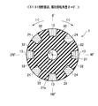
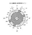
- FIG. 6 is a cross-sectional view of the joint structure according to the first embodiment, corresponding to a cross section taken along line X1-X1 of FIG.
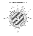
- FIG. 6 is a cross-sectional view of the joint structure according to the first embodiment, corresponding to a cross section taken along line X2-X2 of FIG.
- FIG. 11 is a cross-sectional view of a joint structure according to a second embodiment, corresponding to a cross section taken along line X3-X3 of FIG. It is a disassembled perspective view of the joint structure concerning a 3rd embodiment. It is an outer peripheral view of the joint structure concerning a 3rd embodiment. It is a disassembled perspective view of the joint structure concerning a 4th embodiment. It is an outer peripheral view of the joint structure concerning a 4th embodiment. It is an outer peripheral view of the joint structure concerning a 5th embodiment. It is a perspective view of the joint structure concerning a 6th embodiment. It is an outer peripheral view of the joint structure concerning a 6th embodiment.
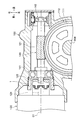
- the electric power steering apparatus 200 is a pinion assist type in which an assist force (assist force) is input to the pinion shaft 208.
- the electric power steering apparatus 200 includes a steering wheel 201 operated by a driver, a steering shaft 202 (steering column) that rotates integrally with the steering wheel 201, and an intermediate coupled to the steering shaft 202 via a first universal joint 203.
- a rack shaft 209 formed with a rack 209a that meshes with the pinion 208a. Both ends of the rack shaft 209 are connected to a front wheel 211 that is a steered wheel via a tie rod 210.
- the electric power steering apparatus 200 includes a worm wheel 110 fixed to the pinion shaft 208 and a worm 120 (second rotation shaft, transmission member) that meshes with the gear teeth 111 of the worm wheel 110.
- the electric motor 130 that generates assist force (power), and the joint structure 1 that connects the output shaft 131 (first rotation shaft) of the motor 130 and the worm 120 are provided. That is, the worm 120 is a transmission member that transmits the assist force from the motor 130 to the pinion shaft 208 that is a part of the steering device that steers the front wheels 211.
- the worm 120 is an elongated cylindrical part, and includes a gear tooth 121 that meshes with the gear tooth 111 of the worm wheel 110 at an intermediate portion thereof.
- a spline shaft portion 122 that is spline-coupled with a second engagement member 20 (see FIG. 4) described later is formed.
- the worm 120 is rotatably supported by the housing 150 via a front bearing 141 and a rear bearing 142.
- the bearing 141 and the bearing 142 are constituted by radial ball bearings, for example.
- the joint structure 1 is a structure that connects the output shaft 131 (first rotating shaft) and the worm 120 (second rotating shaft) of the motor 130 so that torque can be transmitted.
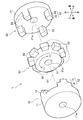
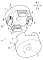
- the joint structure 1 includes a first engagement member 10 (first coupling) fixed to the output shaft 131, a second engagement member 20 (second coupling) fixed to the worm 120, and a first engagement. And an elastic member 30 (bush) provided between the combined member 10 and the second engaging member 20.
- the first engagement member 10 is a member that is fixed to and integrated with the output shaft 131 of the motor 130 and that engages with the second engagement member 20 and / or the elastic member 30.
- the first engagement member 10 and the second engagement member 20 are made of a hard material having higher rigidity (elastic coefficient, elastic modulus) than the elastic member 30.
- the first engagement member 10 and the second engagement member 20 are formed of a material such as a metal (including an alloy), a sintered material, a hard synthetic resin, or a ceramic.
- the first engagement member 10 includes a first main body 11 and four first engagement claws 12 (first engagement portions) integrally formed with the first main body 11 and extending rearward from the first main body 11. I have.
- claw 12 may be a structure which is another components. Further, the number of the first engaging claws 12 is not limited to four, and may be one, two, three, five, or more.
- the 1st main body 11 is exhibiting the shape of a short cylinder base, and is the part which the output shaft 131 of the motor 130 connects, and the spline hole 11a is formed on the center axis line. That is, the first main body 11 is fixed and connected to the output shaft 131 by the spline coupling between the output shaft 131 and the spline hole 11a.
- the first main body 11 is not limited to the short cylindrical pedestal shape, and may be, for example, a square pedestal shape, a star pedestal shape, a hemispherical pedestal shape, or the like.
- the coupling method (fixing method) between the first main body 11 and the output shaft 131 is not limited to the spline coupling, but may be, for example, a press-fit fixing method or an integral molding method. Further, the first body 11 and the output shaft 131 may be integrally formed.
- Each of the first engagement claws 12 is an elongated rectangular pillar piece extending from the outer peripheral edge of the first main body 11 toward the second engagement member 20 along the rotation axis O1.
- the rotation axis O ⁇ b> 1 is the rotation axis of the joint structure 1.
- claw 12 is not limited to this.
- the four first engaging claws 12 are arranged at equal intervals (90 ° intervals) in the circumferential direction (rotation direction of the motor 130).
- Each first engaging claw 12 includes a first distal end portion 13 (first holding portion) on the distal end side (rear side), and a first proximal end portion 14 (first direct contact portion) on the proximal end side (front side). It is equipped with.
- the first tip 13 is a part that always contacts and holds the elastic claw 32 to be described later in the circumferential direction.
- the first base end portion 14 is the predetermined angle ⁇ 1 (FIGS. 7 and 8).
- Reference which is a portion that comes into direct contact with a second tip 23 described later.
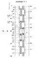
- the circumferential length ⁇ L14 (width) of the first base end portion 14 is configured to be longer than the circumferential length ⁇ L13 (width) of the first distal end portion 13 (see FIG. 5). That is, the both side surfaces of the first engagement claw 12 are stepped surfaces. Thereby, the elastic claw 32 is held by engaging with the first base end portion 14 in the axial direction, so that the elastic claw 32 is not displaced forward.
- a slit 91 (gap between the first base end portion 14 and a second distal end portion 23 described later) , Clearance) in the circumferential direction ⁇ L91 is shorter than the circumferential length ⁇ L32 of the elastic claw 32.
- the second engagement member 20 is a member that is fixed to and integrated with the spline shaft portion 122 of the worm 120 and that engages with the first engagement member 10 and / or the elastic member 30.
- the 2nd engagement member 20 is the structure similar to the 1st engagement member 10, the description is abbreviate
- the second engagement member 20 includes a second main body 21 and four second engagement claws 22 (second engagement portions) integrally formed with the second main body 21 and extending forward from the second main body 21.
- claw 22 may be a structure which is another components.
- the number of the second engaging claws 22 is not limited to four, and may be one, two, three, five, or more.
- the 2nd main body 21 is exhibiting the shape of a short cylinder base, and is the part which the spline shaft part 122 of the worm
- the second main body 21 is not limited to a short cylindrical pedestal shape, and may be, for example, a square pedestal shape, a star pedestal shape, a hemispherical pedestal shape, or the like.
- bonding method (fixing method) of the 2nd main body 21 and the spline shaft part 122 is not limited to spline coupling
- the structure by which the 2nd main body 21 and the spline shaft part 122 were formed integrally may be sufficient.
- Each of the second engagement claws 22 is an elongated rectangular pillar piece extending from the outer peripheral edge of the second main body 21 toward the first engagement member 10 along the rotation axis O1.
- the shape of the second engagement claw 22 is not limited to this.
- the four second engaging claws 22 are arranged at equal intervals (90 ° intervals) in the circumferential direction (the rotation direction of the motor 130).
- Each of the second engagement claws 22 includes a second distal end portion 23 on the distal end side (rear side) and a second proximal end portion 24 on the proximal end side (front side).
- the second distal end portion 23 is a portion that directly contacts the first base end portion 14 when the relative rotation angle ⁇ is the predetermined angle ⁇ 1.
- the second base end portion 24 is a portion that always contacts the elastic claw 32.
- the elastic member 30 is an elastic member provided between the first engagement member 10 and the second engagement member 20, and is between the first engagement member 10 and the second engagement member 20. It is a member that transmits torque.
- the elastic member 30 is formed of a soft material having lower rigidity (elastic coefficient (elastic modulus)) than the first engaging member 10 and the second engaging member 20.
- the elastic member 30 is formed of a material such as synthetic rubber (silicon rubber, urethane rubber, etc.), natural rubber, soft synthetic resin (urethane, polyester elastomer), or the like.
- the elastic member 30 includes a cylindrical elastic member main body 31 and eight elastic claws 32 extending radially outward from the rear side of the outer peripheral surface of the elastic member main body 31.
- claw 32 are separate components may be sufficient.
- the number of the elastic claws 32 is not limited to eight and can be changed as appropriate.
- the elastic member main body 31 is a portion sandwiched between the first main body 11 and the second main body 21 in the axial direction.
- the length of the elastic member body 31 in the axial direction is set to approximately twice that of the elastic claw 32.
- a through hole 31a penetrating in the axial direction is formed on the central axis (rotation axis O1) of the elastic member main body 31, a through hole 31a penetrating in the axial direction is formed.
- An elastic member an axial preload member that generates a preload in the axial direction may be inserted into the through hole 31a. That is, the elastic member is disposed in the through hole 31a in a contracted state in the axial direction, and the restoring force urges the second engagement member 20 and the worm 120 integral therewith backward (see FIG. 2), The worm 120 and the worm wheel 110 are engaged at a predetermined position.
- the elastic member include a coil spring and an elastic rod (not shown) formed of an elastic material and having elasticity.
- the elastic rod is formed in, for example, an elongated cylindrical shape or a prismatic shape.
- the elastic rod has elasticity as described above, it can be easily twisted in the circumferential direction, and the first engagement member 10 and the second engagement member 20 can be relatively rotated easily. However, it is good also as a structure which is not provided with the through-hole 31a and an elastic bar.
- the elastic claw 32 is a protruding piece formed on the outer peripheral surface of the elastic member main body 31, and is an elongated rectangular column piece extending in the axial direction.
- the elastic claw 32 is a portion sandwiched between the first distal end portion 13 and the second proximal end portion 24 in the circumferential direction.
- the elastic claw 32 is compressed and deformed (elastically deformed) and the first distal end portion 13 and the second proximal end portion 24 are not in direct contact with each other. There is no sound.
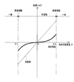
- the elastic claw 32 compresses and absorbs the torque, the torque transmitted from the motor 130 to the worm 120 does not rise rapidly. As a result, the assist force does not increase rapidly, and the driver does not feel uncomfortable. Since the elastic claw 32 is compressed and deformed, the torque transmitted from the first engagement member 10 to the second engagement member 20 is not provided with the elastic claw 32 and the first engagement member 10 and the second engagement member 20 are not provided. Compared to the comparative example in direct contact, it becomes smaller (see FIG. 8).
- “Relative rotation angle ⁇ predetermined angle ⁇ 1”
- the elastic claw 32 is further compressed, and the first base end portion 14 and the second tip end portion 23 are in direct contact (contact) in the circumferential direction.
- the 1st engagement member 10 and the 2nd engagement member 20 are integrated in the circumferential direction, and the 1st engagement member 10 and the 2nd engagement member 20 rotate in one. That is, the output shaft 131, the first engagement member 10, the second engagement member 20, and the worm 120 of the motor 130 rotate integrally. Then, the torque generated by the motor 130 is transmitted to the worm 120 as it is.
- the magnitude of the first torque is proportional to the magnitude of the direct contact area between the first base end portion 14 and the second tip end portion 23.
- the magnitude of the second torque is proportional to the magnitude of the circumferential cross-sectional area of the elastic claw 32.
- the second torque seems to be smaller than the first torque, but it is preferable that the variation in torque in the radial direction is small. That is, the circumferential cross-sectional area of the elastic claw 32 is made larger than the direct contact area, which is the area where the first base end portion 14 and the second tip end portion 23 are in contact, and the first torque and the second torque are made equal. It is preferable. In addition, the second torque may greatly exceed the first torque.
- the relative rotation angle ⁇ reaches the predetermined angle ⁇ 1
- the first base end portion 14 and the second tip end portion 23 are in direct contact with each other, so that the elastic claw 32 is not further compressed and deformed. Thereby, the compressive force subsequently input to the elastic claw 32 is not increased, and the elastic claw 32 is hardly damaged, and durability is improved.
- the power input member (transmission member) to which power is input is exemplified as the worm 120.
- a bevel gear bevel gear
- a spur gear spur gear
- a pinion gear a helical gear
- ha Helical gear
- double helical gear helical gear
- the configuration in which the power output device for outputting power is the motor 130 is exemplified.
- a configuration in which the motor 130 is hydraulic may be used.
- the electric power steering device 200 is exemplified as the pinion assist type, but other configurations such as a column assist type and a rack assist type are also possible. Further, the joint structure 1 may be applied to other than the electric power steering apparatus 200.
- a joint structure 1A according to the second embodiment includes a first engagement member 10A, a second engagement member 20, and an elastic member 30A.
- the first engaging member 10A includes a first main body 11 and four first engaging claws that extend rearward from the first main body 11 and are arranged at equal intervals in the circumferential direction.
- the four first engaging claws are referred to as a first engaging claw 15A, a first engaging claw 15B, a first engaging claw 15A, and a first engaging claw 15B in the circumferential direction. .
- First engagement member-first engagement claw> The circumferential lengths (widths) of the first engaging claws 15A and 15B are constant in the axial direction, and are not different from the first engaging claws 12 (see FIGS. 4 and 5).
- the second engagement member 20 includes a second main body 21 and four second engagement claws extending forward from the second main body 21 and arranged at equal intervals in the circumferential direction.
- the four second engaging claws are referred to as a second engaging claw 22A, a second engaging claw 22B, a second engaging claw 22A, and a second engaging claw 22B in the circumferential direction. .
- the elastic member 30 ⁇ / b> A includes an elastic member main body 31 and four elastic claws extending radially outward from the outer peripheral surface of the elastic member main body 31.
- the four elastic claws are referred to as an elastic claw 33A, an elastic claw 33B, an elastic claw 33A, and an elastic claw 33B in the circumferential direction.
- the elastic claws 33 ⁇ / b> A and the elastic claws 33 ⁇ / b> B are projecting pieces formed on the outer peripheral surface of the elastic member main body 31, and are elongated rectangular pillar pieces extending in the axial direction.
- the axial lengths of the elastic claws 33 ⁇ / b> A and the elastic claws 33 ⁇ / b> B are set to be the same as the axial length of the elastic member body 31.
- the elastic claw 33A is sandwiched between the first engagement claw 15A and the second engagement claw 22A in the circumferential direction (see FIGS. 10 and 11).
- the elastic claw 33B is sandwiched between the first engagement claw 15B and the second engagement claw 22A in the circumferential direction (see FIGS. 10 and 11).
- the elastic claw 33A is only in contact with the first engagement claw 15A and the second engagement claw 22A and is not compressed. The same applies to the elastic claw 33B. Then, slits 92 having a circumferential length ⁇ L92 are formed on both sides in the circumferential direction of the second engagement claw 22B. The center angle of the slit 92 is set to a predetermined angle ⁇ 1.
- a joint structure 1B according to the third embodiment includes a first engagement member 10B, a second engagement member 20B, and four elastic members 30B.
- the first engagement member 10B includes a first main body 11 and four first engagement claws 16 extending from the first main body 11 toward the second engagement member 20B.
- the four first engaging claws 16 are arranged at equal intervals in the circumferential direction.
- the second engagement member 20B includes a second main body 21 and four second engagement claws 25 extending from the second main body 21 toward the first engagement member 10B.
- the four second engaging claws 25 are arranged at equal intervals in the circumferential direction.
- a groove 25 a (second holding portion) extending in the circumferential direction is formed at an axially intermediate position on the outer peripheral surface of the second engagement claw 25.
- the groove 25a is a groove in which the elastic member 30B is mounted and is a groove that holds the elastic member 30B in the axial direction. That is, the elastic member 30B is positioned with respect to the second engaging claw 25 by fitting the elastic member 30B into the groove 25a.
- the depth of the groove 25a is set to, for example, approximately 1 ⁇ 2 of the thickness of the elastic member 30B.
- the groove 25a is not limited to the intermediate position in the axial direction, and may be formed on the distal end side (front side) or the proximal end side (rear side) of the second engagement claw 25.
- the elastic member 30B is provided between the first engagement claw 16 and the second engagement claw 25 in the circumferential direction, and transmits a torque between the first engagement claw 16 and the second engagement claw 25. It is.
- the elastic member 30B is an annular member, and has a circular cross section.
- “Relative rotation angle ⁇ 0 °”
- the elastic member 30B is in contact with the first engagement claw 16 and the second engagement claw 25 in the circumferential direction, but is not compressed. Specifically, in the circumferential direction, the first engagement claw 16, the second engagement claw 25, the first engagement claw 16, the second engagement claw 25,.
- a slit 93 having a circumferential length ⁇ L93 is formed between the first engagement claw 16 and the portion of the second engagement claw 25 where the groove 25a is not formed.
- the central angle of the slit 93 is a predetermined angle ⁇ 1.
- the joint structure 1B according to the fourth embodiment includes an endless belt-like (belt-like) elastic member 30C instead of the elastic member 30B. That is, the cross section of the elastic member 30C has a rectangular shape whose longitudinal direction is the longitudinal direction. Therefore, the contact area between the elastic member 30C and the second engagement claw 25 or the first engagement claw 16 is larger than the contact area with respect to the elastic member 30B (see FIG. 13) having a circular cross section.
- a groove 25b (second holding portion) having a rectangular shape in a sectional view corresponding to the elastic member 30B is formed on the outer peripheral surface of the second engagement claw 25.
- an elastic member 30 ⁇ / b> D similar to the elastic member 30 ⁇ / b> B is also attached to the first engagement claw 16.
- the first engaging claw 16 is formed with a groove 16a (first holding portion) that holds the elastic member 30 in the axial direction.
- the elastic member 30B and the elastic member 30D are displaced in the axial direction.
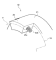
- the joint structure 1D according to the sixth embodiment includes a compression coil spring 30E (elastic member).
- the compression coil springs 30 ⁇ / b> E are respectively attached to holes 25 c formed on both side surfaces in the circumferential direction of the second engagement claws 25. That is, one end side of the compression coil spring 30E is inserted into the hole 25c, and the other end side of the compression coil spring 30E protrudes from the hole 25c and abuts on the circumferential side surface of the first engagement claw 16.
- a hole into which the compression coil spring 30 ⁇ / b> E is inserted may also be formed in the first engagement claw 16. Moreover, it is good also as a structure provided with the elastic member which replaces with the compression coil spring 30E and consists of a rubber-made cylinder.
Landscapes
- Engineering & Computer Science (AREA)
- General Engineering & Computer Science (AREA)
- Mechanical Engineering (AREA)
- Chemical & Material Sciences (AREA)
- Combustion & Propulsion (AREA)
- Transportation (AREA)
- Power Steering Mechanism (AREA)
Abstract
Description
本発明の第1実施形態について、図1~図8を参照して説明する。
電動パワーステアリング装置200は、アシスト力(補助力)がピニオン軸208に入力されるピニオンアシスト型である。
継手構造体1について、図3~図8を参照して説明する。継手構造体1は、モータ130の出力軸131(第1回転軸)とウォーム120(第2回転軸)とをトルク伝達可能に継ぐ構造体である。継手構造体1は、出力軸131に固定される第1係合部材10(第1カップリング)と、ウォーム120に固定される第2係合部材20(第2カップリング)と、第1係合部材10及び第2係合部材20の間に設けられた弾性部材30(ブッシュ)と、を備えている。
第1係合部材10は、モータ130の出力軸131に固定され一体であると共に、第2係合部材20及び/又は弾性部材30と係合する部材である。
第1本体11は、短円柱台座状を呈しており、モータ130の出力軸131が接続する部分であり、その中心軸線上にスプライン孔11aが形成されている。すなわち、出力軸131とスプライン孔11aとがスプライン結合することで、第1本体11が出力軸131に固定され接続されるようになっている。
各第1係合爪12は、回転軸線O1に沿って、第1本体11の外周縁から第2係合部材20に向かって延びる細長の四角柱片である。回転軸線O1は継手構造体1の回転軸線である。ただし、第1係合爪12の形状は、これに限定されない。4本の第1係合爪12は、周方向(モータ130の回転方向)において、等間隔(90°間隔)で配置されている。
第2係合部材20は、ウォーム120のスプライン軸部122に固定され一体であると共に、第1係合部材10及び/又は弾性部材30と係合する部材である。なお、第2係合部材20は、第1係合部材10と同様の構成であるので、その説明を適宜に省略する。
第2本体21は、短円柱台座状を呈しており、ウォーム120のスプライン軸部122が接続する部分であり、その中心軸線上にスプライン孔21aが形成されている。すなわち、スプライン軸部122とスプライン孔21aとがスプライン結合することで、第2本体21がスプライン軸部122に固定され接続されるようになっている。
各第2係合爪22は、回転軸線O1に沿って、第2本体21の外周縁から第1係合部材10に向かって延びる細長の四角柱片である。ただし、第2係合爪22の形状は、これに限定されない。4本の第2係合爪22は、周方向(モータ130の回転方向)において、等間隔(90°間隔)で配置されている。
弾性部材30は、第1係合部材10と第2係合部材20との間に設けられた弾性を有する部材であって、第1係合部材10と第2係合部材20との間でトルクを伝達させる部材である。
弾性部材本体31は、軸方向において、第1本体11と第2本体21とで挟持される部分である。弾性部材本体31の軸方向長さは、弾性爪32の略2倍に設定されている。
弾性爪32は、弾性部材本体31の外周面に形成された突出片であり、軸方向に延びる細長の四角柱片である。弾性爪32は、周方向において、第1先端部13と第2基端部24とで挟まれる部分である。
継手構造体1(電動パワーステアリング装置200)の作用効果を説明する。
相対回転角度θが0°である場合を説明する。なお、相対回転角度θが0°である状態は、モータ130が停止し、弾性部材30が周方向において圧縮されておらず、第2係合爪22が2本の第1係合爪12の周方向中間に配置されている状態である。
モータ130が回転し、「0°<相対回転角度θ<θ1」である場合を説明する。なお、ここでは、図3~図8において、モータ130側の第1係合部材10がウォーム120側の第2係合部材20に対して右回転した場合を「+(プラス)側」とし、第1係合部材10がウォーム120側の第2係合部材20に対して左回転した場合を「-(マイナス)側」とする。
相対回転角度θが所定角度θ1に到達した場合、弾性爪32はさらに圧縮され、周方向において、第1基端部14と第2先端部23とが直接接触(当接)する。これにより、第1係合部材10と第2係合部材20とは周方向において一体化し、第1係合部材10及び第2係合部材20が一体で回転する。すなわち、モータ130の出力軸131、第1係合部材10、第2係合部材20及びウォーム120が、一体で回転する。そうすると、モータ130で発生したトルクがそのままウォーム120に伝達される。
このようにモータ130の回転開始後、第1先端部13及び第2基端部24が周方向において弾性爪32を挟み直接接触しないので、第1係合部材10及び第2係合部材20の間で歯打ち音が発生せず、伝達するトルクが急上昇しない。これにより、運転者が操舵フィーリングにおいて違和感を受けることは無く、第1係合部材10及び第2係合部材20が折損等し難くなる。
以上、本発明の第1実施形態について説明したが、本発明はこれに限定されず、例えば、次のように変更してもよいし、後記する実施形態の構成と適宜に組み合わせてもよい。
次に、本発明の第2実施形態について、図9~図11を参照して説明する。なお、第1実施形態と異なる部分を説明する。
第2実施形態に係る継手構造体1Aは、第1係合部材10Aと、第2係合部材20と、弾性部材30Aと、を備えている。
第1係合部材10Aは、第1本体11と、第1本体11から後方に延びると共に周方向に等間隔で配置された4本の第1係合爪と、を備えている。ここで、説明の都合上、4本の第1係合爪を周方向において、第1係合爪15A、第1係合爪15B、第1係合爪15A、第1係合爪15Bとする。
第1係合爪15A、15Bの周方向長さ(幅)は、軸方向において一定であり、第1係合爪12(図4、図5参照)のように段違いでない。
第2係合部材20は、第2本体21と、第2本体21から前方に延びると共に周方向に等間隔で配置された4本の第2係合爪と、を備えている。ここで、説明の都合上、4本の第2係合爪を周方向において、第2係合爪22A、第2係合爪22B、第2係合爪22A、第2係合爪22Bとする。
弾性部材30Aは、弾性部材本体31と、弾性部材本体31の外周面から径方向外向きに延びる4本の弾性爪と、を備えている。ここで、説明の都合上、4本の弾性爪を周方向において、弾性爪33A、弾性爪33B、弾性爪33A、弾性爪33Bとする。
弾性爪33A、弾性爪33Bは、弾性部材本体31の外周面に形成された突出片であり、軸方向に延びる細長の四角柱片である。弾性爪33A、弾性爪33Bの軸方向長さは、弾性部材本体31の軸方向長さと同一に設定されている。弾性爪33Aは、周方向において、第1係合爪15Aと第2係合爪22Aとで挟まれている(図10、図11参照)。弾性爪33Bは、周方向において、第1係合爪15Bと第2係合爪22Aとで挟まれている(図10、図11参照)。
継手構造体1Aの作用効果を説明する。
相対回転角度θが0°である場合を説明する。
弾性爪33A、弾性爪33Bを通る輪切り断面(X3-X3線断面)の周方向において、第1係合爪15A、弾性爪33A、第2係合爪22A、弾性爪33B、第1係合爪15B、スリット92、第2係合爪22B、スリット92、第1係合爪15A、弾性爪33A、第2係合爪22A、弾性爪33B、第1係合爪15B、スリット92、の順で配置されている。
モータ130が「+側」で回転し、「0°<相対回転角度θ<θ1」である場合を説明する。
相対回転角度θが0°よりも大きくなると、第1係合爪15Aと第2係合爪22Aとが弾性爪33Aを圧縮し、第1係合部材10Aから第2係合部材20にトルクが伝達される。このように、第1係合爪15A及び第2係合爪22Aが弾性爪33Aを圧縮変形し、第1係合爪15A及び第2係合爪22Aが直接接触しないので、第1係合爪15A及び第2係合爪22Aの間で歯打ち音が発生せず、伝達するトルクが急上昇することはない。
相対回転角度θが所定角度θ1に到達した場合、弾性爪33はさらに圧縮され、周方向において、第1係合爪15Bと第2係合爪22Bとが直接接触(当接)する。これにより、第1係合部材10及び第2係合部材20が一体で回転する。すなわち、モータ130の出力軸131、第1係合部材10A、第2係合部材20及びウォーム120が、一体で回転する。そうすると、モータ130で発生したトルクがそのままウォーム120に伝達される。
次に、本発明の第3実施形態について、図12~図13を参照して説明する。なお、第1実施形態と異なる部分を説明する。
第3実施形態に係る継手構造体1Bは、第1係合部材10Bと、第2係合部材20Bと、4本の弾性部材30Bと、を備えている。
第1係合部材10Bは、第1本体11と、第1本体11から第2係合部材20Bに向かって延びる4本の第1係合爪16と、を備えている。4本の第1係合爪16は、周方向において等間隔で配置されている。
第2係合部材20Bは、第2本体21と、第2本体21から第1係合部材10Bに向かって延びる4本の第2係合爪25と、を備えている。4本の第2係合爪25は、周方向において等間隔で配置されている。
第2係合爪25の外周面の軸方向中間位置には、周方向に延びる溝25a(第2保持部)が形成されている。溝25aは、弾性部材30Bが装着される溝であって、弾性部材30Bを軸方向において保持する溝である。すなわち、弾性部材30Bが溝25aに嵌合することで、弾性部材30Bは第2係合爪25に対して位置決めされるようになっている。なお、溝25aの深さは、例えば、弾性部材30Bの太さの略1/2に設定されている。また、溝25aは軸方向中間位置に限定されず、第2係合爪25の先端側(前側)又は基端側(後側)に形成してもよい。
弾性部材30Bは、周方向において第1係合爪16と第2係合爪25との間に設けられ、第1係合爪16と第2係合爪25との間でトルクを伝達させる部材である。弾性部材30Bは、環状部材であって、その断面は円形を呈している。
継手構造体1Bの作用効果を説明する。
相対回転角度θが0°である場合、弾性部材30Bは周方向において第1係合爪16及び第2係合爪25に接触しているものの圧縮されていない。具体的には、周方向において、第1係合爪16、第2係合爪25、第1係合爪16、第2係合爪25、…、の順で配列している。
相対回転角度θが0°よりも大きくなると、第1係合爪16と第2係合爪25とが弾性部材30Bを圧縮し、第1係合部材10Bから第2係合部材20Bにトルクが伝達される。トルクの伝達開始時、第1係合爪16及び第2係合爪25が弾性部材30Bを圧縮変形し、第1係合爪16及び第2係合爪25が直接接触しないので、第1係合爪16及び第2係合爪25の間で歯打ち音が発生しない。
相対回転角度θが所定角度θ1に到達した場合、弾性部材30Bはさらに圧縮され、周方向において、第1係合爪16と第2係合爪25の溝25a以外の部分(第2直接接触部)とが直接接触する。これにより、第1係合部材10Bと第2係合部材20Bとは周方向において一体化し、第1係合部材10B及び第2係合部材20Bが一体で回転する。
次に、本発明の第4実施形態について、図14~図15を参照して説明する。
次に、本発明の第5実施形態について、図16を参照して説明する。
図16に示すように、第5実施形態に係る継手構造体1Cでは、弾性部材30Bと同様の弾性部材30Dが第1係合爪16にも装着されている。第1係合爪16には、弾性部材30を軸方向において保持する溝16a(第1保持部)が形成されている。弾性部材30Bと弾性部材30Dとは軸方向にずれている。この他、弾性部材30Bを備えず、弾性部材30Dのみを備える構成としてもよい。
次に、本発明の第6実施形態について、図17~図18を参照して説明する。
図17~図18に示すように、第6実施形態に係る継手構造体1Dは、圧縮コイルばね30E(弾性部材)を備えている。圧縮コイルばね30Eは、第2係合爪25の周方向両側面に形成された穴25cにそれぞれ装着されている。すなわち、圧縮コイルばね30Eの一端側は穴25cに差し込まれており、圧縮コイルばね30Eの他端側は穴25cから突出し第1係合爪16の周方向側面に当接している。なお、第1係合爪16にも圧縮コイルばね30Eが差し込まれる穴を形成してもよい。また、圧縮コイルばね30Eに代えて、ゴム製の円柱体から成る弾性部材を備える構成としてもよい。
10、10A、10B 第1係合部材
11 第1本体
12、15、15A、15B、16 第1係合爪(第1係合部)
13 第1先端部(第1保持部)
14 第1基端部(第1直接接触部)
16a 溝(第1保持部)
20、20B 第2係合部材
21 第2本体
22、22A、22B、25 第2係合爪(第2係合部)
23 第2先端部(第2直接接接触部)
24 第2基端部
25a、25b 溝(第2保持部)
25c 穴(第2保持部)
30、30A、30B、30C、30D 弾性部材
30E 圧縮コイルばね(弾性部材)
31 弾性部材本体
31a 貫通孔
32、33A、33B 弾性爪
91、92、93 スリット
120 ウォーム(第2回転軸、伝達部材)
130 モータ
131 出力軸(第1回転軸)
200 電動パワーステアリング装置
Claims (8)
- 第1回転軸と一体である第1係合部材と、
第2回転軸と一体である第2係合部材と、
前記第1係合部材及び前記第2係合部材の間に設けられ、前記第1係合部材及び前記第2係合部材の間で回転力を伝達させると共に、弾性を有する弾性部材と、
を備え、
前記第1係合部材は、前記第1回転軸と一体である第1本体と、前記第1本体から延びる1又は複数の第1係合部と、を備え、
前記第2係合部材は、前記第2回転軸と一体である第2本体と、前記第2本体から延びる1又は複数の第2係合部と、を備え、
前記弾性部材は、周方向において前記第1係合部と前記第2係合部との間に配置され、
前記第1係合部材及び前記第2係合部材の相対回転角度が所定角度未満である場合、前記第1係合部及び前記第2係合部が周方向において直接接触せず、回転力が弾性変形する前記弾性部材を介して伝達し、
前記相対回転角度が前記所定角度である場合、前記第1係合部及び前記第2係合部が周方向において直接接触する
ことを特徴とする継手構造体。 - 前記第1係合部は、前記弾性部材を軸方向において保持する第1保持部と、前記相対回転角度が前記所定角度である場合に前記第2係合部に直接接触する第1直接接触部と、を備える
ことを特徴とする請求項1に記載の継手構造体。 - 前記第2係合部は、前記弾性部材を軸方向において保持する第2保持部と、前記相対回転角度が前記所定角度である場合に前記第1係合部に直接接触する第2直接接触部と、を備える
ことを特徴とする請求項1に記載の継手構造体。 - 前記第2係合部は、前記弾性部材を軸方向において保持する第2保持部と、前記相対回転角度が前記所定角度である場合に前記第1係合部に直接接触する第2直接接触部と、を備える
ことを特徴とする請求項2に記載の継手構造体。 - 請求項1に記載の継手構造体を備え、
前記第1回転軸は、アシスト力を発生するモータの出力軸であり、
前記第2回転軸は、前記アシスト力を操舵装置に伝達する伝達部材である
ことを特徴とするパワーステアリング装置。 - 請求項2に記載の継手構造体を備え、
前記第1回転軸は、アシスト力を発生するモータの出力軸であり、
前記第2回転軸は、前記アシスト力を操舵装置に伝達する伝達部材である
ことを特徴とするパワーステアリング装置。 - 請求項3に記載の継手構造体を備え、
前記第1回転軸は、アシスト力を発生するモータの出力軸であり、
前記第2回転軸は、前記アシスト力を操舵装置に伝達する伝達部材である
ことを特徴とするパワーステアリング装置。 - 請求項4に記載の継手構造体を備え、
前記第1回転軸は、アシスト力を発生するモータの出力軸であり、
前記第2回転軸は、前記アシスト力を操舵装置に伝達する伝達部材である
ことを特徴とするパワーステアリング装置。
Priority Applications (5)
| Application Number | Priority Date | Filing Date | Title |
|---|---|---|---|
| JP2015530648A JP6118902B2 (ja) | 2013-08-09 | 2013-08-09 | パワーステアリング装置用の継手構造体 |
| CN201380078843.7A CN105452695B (zh) | 2013-08-09 | 2013-08-09 | 联结结构和动力转向装置 |
| PCT/JP2013/071676 WO2015019496A1 (ja) | 2013-08-09 | 2013-08-09 | 継手構造体及びパワーステアリング装置 |
| DE112013007327.7T DE112013007327T5 (de) | 2013-08-09 | 2013-08-09 | Verbindungsstruktur und Servolenkungseinrichtung |
| US15/015,914 US9777776B2 (en) | 2013-08-09 | 2016-02-04 | Joint structure and power steering device |
Applications Claiming Priority (1)
| Application Number | Priority Date | Filing Date | Title |
|---|---|---|---|
| PCT/JP2013/071676 WO2015019496A1 (ja) | 2013-08-09 | 2013-08-09 | 継手構造体及びパワーステアリング装置 |
Related Child Applications (1)
| Application Number | Title | Priority Date | Filing Date |
|---|---|---|---|
| US15/015,914 Continuation US9777776B2 (en) | 2013-08-09 | 2016-02-04 | Joint structure and power steering device |
Publications (1)
| Publication Number | Publication Date |
|---|---|
| WO2015019496A1 true WO2015019496A1 (ja) | 2015-02-12 |
Family
ID=52460862
Family Applications (1)
| Application Number | Title | Priority Date | Filing Date |
|---|---|---|---|
| PCT/JP2013/071676 Ceased WO2015019496A1 (ja) | 2013-08-09 | 2013-08-09 | 継手構造体及びパワーステアリング装置 |
Country Status (5)
| Country | Link |
|---|---|
| US (1) | US9777776B2 (ja) |
| JP (1) | JP6118902B2 (ja) |
| CN (1) | CN105452695B (ja) |
| DE (1) | DE112013007327T5 (ja) |
| WO (1) | WO2015019496A1 (ja) |
Families Citing this family (14)
| Publication number | Priority date | Publication date | Assignee | Title |
|---|---|---|---|---|
| JP6015613B2 (ja) * | 2013-09-25 | 2016-10-26 | トヨタ自動車株式会社 | 車両用動力伝達装置のスプライン位置出し歯打ち緩衝機構 |
| US9873448B2 (en) * | 2014-03-31 | 2018-01-23 | Steering Solutions Ip Holding Corporation | End of travel stop |
| US9341996B1 (en) * | 2015-04-09 | 2016-05-17 | Lexmark International, Inc. | Hub-based drive coupling mechanism for a fuser backup member and methods of using same |
| CN106904214B (zh) * | 2015-12-22 | 2019-05-03 | 蒂森克虏伯普利斯坦汽车零部件(上海)有限公司 | 电动助力转向系统的电机与蜗杆连接装置 |
| DE102016002436B4 (de) | 2016-03-01 | 2022-07-21 | Liebherr-Werk Telfs Gmbh | Baumaschine mit einer Vorrichtung zum Entkoppeln eines Hydraulikmotors |
| DE202016101746U1 (de) * | 2016-04-01 | 2017-07-06 | Renold Plc | Mechanische Kupplung |
| CN109790873B (zh) * | 2016-10-13 | 2021-08-31 | 日本精工株式会社 | 力矩传递用接头和电动式助力转向装置 |
| FR3067432A1 (fr) * | 2017-06-09 | 2018-12-14 | Solystic | Poulie a double pignons pour la synchronisation de courroies |
| KR102584761B1 (ko) * | 2018-09-03 | 2023-10-06 | 에이치엘만도 주식회사 | 조향장치의 동력 전달부재 |
| DE102019218997A1 (de) * | 2019-12-05 | 2021-06-10 | Robert Bosch Gmbh | Lenkgetriebe für ein Lenksystem eines Kraftfahrzeugs |
| CN112061232A (zh) * | 2020-09-29 | 2020-12-11 | 西安电子科技大学芜湖研究院 | 一种商用车智能电动助力转向系统 |
| KR20230036461A (ko) * | 2021-09-07 | 2023-03-14 | 에이치엘만도 주식회사 | 댐퍼 및 이를 포함하는 스티어링 장치의 구동부 |
| CN115095609A (zh) * | 2022-07-07 | 2022-09-23 | 张长义 | 一种减震联轴器 |
| CN115789118B (zh) * | 2022-10-31 | 2023-06-27 | 泰尔重工股份有限公司 | 一种分体式弹性联轴器、传动机构及设备 |
Citations (4)
| Publication number | Priority date | Publication date | Assignee | Title |
|---|---|---|---|---|
| JPH01120428A (ja) * | 1987-10-30 | 1989-05-12 | Kubota Ltd | エンジン動力伝達構造 |
| JP2007040315A (ja) * | 2005-07-29 | 2007-02-15 | Nsk Ltd | 動力伝達機構とこれを組み込んだ電動式パワーステアリング装置 |
| JP2007082349A (ja) * | 2005-09-15 | 2007-03-29 | Aisin Ai Co Ltd | モータ式アクチュエータの騒音防止機構及びこれを使用した自動変速装置 |
| JP2008260471A (ja) * | 2007-04-13 | 2008-10-30 | Nsk Ltd | 電動式パワーステアリング装置 |
Family Cites Families (13)
| Publication number | Priority date | Publication date | Assignee | Title |
|---|---|---|---|---|
| JPS5615827U (ja) * | 1979-07-17 | 1981-02-10 | ||
| JPH0518905Y2 (ja) * | 1987-11-05 | 1993-05-19 | ||
| US6394248B1 (en) * | 2000-05-31 | 2002-05-28 | Ntn Corporation | Compression spring complaint one-way over-running clutch pulley |
| JP4007159B2 (ja) * | 2002-10-30 | 2007-11-14 | 株式会社ジェイテクト | 電動パワーステアリング装置及びジョイント |
| JP4385286B2 (ja) | 2004-01-29 | 2009-12-16 | 株式会社ジェイテクト | 電動パワーステアリング装置 |
| JP4299718B2 (ja) | 2004-04-20 | 2009-07-22 | 本田技研工業株式会社 | 電動パワーステアリング装置 |
| JP2006175891A (ja) * | 2004-12-20 | 2006-07-06 | Favess Co Ltd | 電動パワーステアリング装置 |
| WO2007000140A2 (de) * | 2005-06-28 | 2007-01-04 | Luk Lamellen Und Kupplungsbau Beteiligungs Kg | Kupplungssystem |
| EP1953404B1 (de) * | 2007-02-05 | 2014-07-02 | Getrag Ford Transmissions GmbH | Kupplungsvorrichtung mit Schenkelfeder |
| CN201090620Y (zh) * | 2007-10-12 | 2008-07-23 | 中国有色集团沈阳冶金机械有限公司 | 轴之间的联接装置 |
| JP5048804B2 (ja) * | 2010-03-31 | 2012-10-17 | 日立オートモティブシステムズ株式会社 | パワーステアリング装置 |
| CN201818675U (zh) * | 2010-09-17 | 2011-05-04 | 四川眉山强力机械有限公司 | 梅花型弹性联轴器 |
| CN102494043B (zh) * | 2011-12-10 | 2015-08-12 | 绿田机械股份有限公司 | 一种弹性联轴器 |
-
2013
- 2013-08-09 DE DE112013007327.7T patent/DE112013007327T5/de not_active Withdrawn
- 2013-08-09 CN CN201380078843.7A patent/CN105452695B/zh not_active Expired - Fee Related
- 2013-08-09 JP JP2015530648A patent/JP6118902B2/ja not_active Expired - Fee Related
- 2013-08-09 WO PCT/JP2013/071676 patent/WO2015019496A1/ja not_active Ceased
-
2016
- 2016-02-04 US US15/015,914 patent/US9777776B2/en not_active Expired - Fee Related
Patent Citations (4)
| Publication number | Priority date | Publication date | Assignee | Title |
|---|---|---|---|---|
| JPH01120428A (ja) * | 1987-10-30 | 1989-05-12 | Kubota Ltd | エンジン動力伝達構造 |
| JP2007040315A (ja) * | 2005-07-29 | 2007-02-15 | Nsk Ltd | 動力伝達機構とこれを組み込んだ電動式パワーステアリング装置 |
| JP2007082349A (ja) * | 2005-09-15 | 2007-03-29 | Aisin Ai Co Ltd | モータ式アクチュエータの騒音防止機構及びこれを使用した自動変速装置 |
| JP2008260471A (ja) * | 2007-04-13 | 2008-10-30 | Nsk Ltd | 電動式パワーステアリング装置 |
Also Published As
| Publication number | Publication date |
|---|---|
| DE112013007327T5 (de) | 2016-06-02 |
| US20160146262A1 (en) | 2016-05-26 |
| JP6118902B2 (ja) | 2017-04-19 |
| JPWO2015019496A1 (ja) | 2017-03-02 |
| US9777776B2 (en) | 2017-10-03 |
| CN105452695B (zh) | 2018-12-11 |
| CN105452695A (zh) | 2016-03-30 |
Similar Documents
| Publication | Publication Date | Title |
|---|---|---|
| JP6118902B2 (ja) | パワーステアリング装置用の継手構造体 | |
| JP4921762B2 (ja) | 伸縮自在シャフトおよび車両操舵用伸縮自在シャフト | |
| JP6020893B2 (ja) | 電動パワーステアリング装置 | |
| EP3156679B1 (en) | Shaft coupling mechanism for electric power steering device | |
| JP6118750B2 (ja) | ウォーム付勢構造体 | |
| EP2500594A1 (en) | Shaft coupling mechanism | |
| KR20040058051A (ko) | 전동식 파워스티어링장치 | |
| JP4952677B2 (ja) | 弾性軸継手及び電動式パワーステアリング装置 | |
| JP6277895B2 (ja) | トルク伝達部材及び駆動軸と被駆動軸との結合部 | |
| JP6164477B2 (ja) | 電動パワーステアリング装置 | |
| EP3135940A1 (en) | Shaft coupling structure and electric power steering system | |
| EP1714851A1 (en) | Electric power steering device | |
| CN102398627A (zh) | 电动动力转向装置 | |
| JP5217676B2 (ja) | ウォーム減速機付回転駆動装置 | |
| JP2007106402A (ja) | 操向装置のスリップジョイント | |
| JP5618146B2 (ja) | 電動パワーステアリング装置 | |
| JP5181747B2 (ja) | 電動式パワーステアリング装置 | |
| JP2015113051A (ja) | パワーステアリング装置 | |
| JP6057611B2 (ja) | 軸連結機構 | |
| JP5256958B2 (ja) | 電動式パワーステアリング装置 | |
| JP2012087881A (ja) | 動力伝達継手および電動パワーステアリング装置 | |
| JP5553105B2 (ja) | 電動式パワーステアリング装置 | |
| JP2008260471A (ja) | 電動式パワーステアリング装置 | |
| KR102111294B1 (ko) | 스티어 바이 와이어식 조향장치 | |
| JP2009061898A (ja) | 電動式パワーステアリング装置 |
Legal Events
| Date | Code | Title | Description |
|---|---|---|---|
| WWE | Wipo information: entry into national phase |
Ref document number: 201380078843.7 Country of ref document: CN |
|
| 121 | Ep: the epo has been informed by wipo that ep was designated in this application |
Ref document number: 13891138 Country of ref document: EP Kind code of ref document: A1 |
|
| ENP | Entry into the national phase |
Ref document number: 2015530648 Country of ref document: JP Kind code of ref document: A |
|
| WWE | Wipo information: entry into national phase |
Ref document number: 112013007327 Country of ref document: DE |
|
| 122 | Ep: pct application non-entry in european phase |
Ref document number: 13891138 Country of ref document: EP Kind code of ref document: A1 |