WO2015015754A1 - 車両用冷凍サイクル装置 - Google Patents
車両用冷凍サイクル装置 Download PDFInfo
- Publication number
- WO2015015754A1 WO2015015754A1 PCT/JP2014/003840 JP2014003840W WO2015015754A1 WO 2015015754 A1 WO2015015754 A1 WO 2015015754A1 JP 2014003840 W JP2014003840 W JP 2014003840W WO 2015015754 A1 WO2015015754 A1 WO 2015015754A1
- Authority
- WO
- WIPO (PCT)
- Prior art keywords
- pump
- heat medium
- cooling water
- heat
- temperature
- Prior art date
- Legal status (The legal status is an assumption and is not a legal conclusion. Google has not performed a legal analysis and makes no representation as to the accuracy of the status listed.)
- Ceased
Links
Images





Classifications
-
- B—PERFORMING OPERATIONS; TRANSPORTING
- B60—VEHICLES IN GENERAL
- B60H—ARRANGEMENTS OF HEATING, COOLING, VENTILATING OR OTHER AIR-TREATING DEVICES SPECIALLY ADAPTED FOR PASSENGER OR GOODS SPACES OF VEHICLES
- B60H1/00—Heating, cooling or ventilating devices
- B60H1/32—Cooling devices
- B60H1/3204—Cooling devices using compression
- B60H1/3205—Control means therefor
- B60H1/3211—Control means therefor for increasing the efficiency of a vehicle refrigeration cycle
-
- B—PERFORMING OPERATIONS; TRANSPORTING
- B60—VEHICLES IN GENERAL
- B60H—ARRANGEMENTS OF HEATING, COOLING, VENTILATING OR OTHER AIR-TREATING DEVICES SPECIALLY ADAPTED FOR PASSENGER OR GOODS SPACES OF VEHICLES
- B60H1/00—Heating, cooling or ventilating devices
- B60H1/32—Cooling devices
- B60H1/3204—Cooling devices using compression
- B60H1/3228—Cooling devices using compression characterised by refrigerant circuit configurations
- B60H1/32284—Cooling devices using compression characterised by refrigerant circuit configurations comprising two or more secondary circuits, e.g. at evaporator and condenser side
-
- F—MECHANICAL ENGINEERING; LIGHTING; HEATING; WEAPONS; BLASTING
- F25—REFRIGERATION OR COOLING; COMBINED HEATING AND REFRIGERATION SYSTEMS; HEAT PUMP SYSTEMS; MANUFACTURE OR STORAGE OF ICE; LIQUEFACTION SOLIDIFICATION OF GASES
- F25B—REFRIGERATION MACHINES, PLANTS OR SYSTEMS; COMBINED HEATING AND REFRIGERATION SYSTEMS; HEAT PUMP SYSTEMS
- F25B1/00—Compression machines, plants or systems with non-reversible cycle
-
- F—MECHANICAL ENGINEERING; LIGHTING; HEATING; WEAPONS; BLASTING
- F25—REFRIGERATION OR COOLING; COMBINED HEATING AND REFRIGERATION SYSTEMS; HEAT PUMP SYSTEMS; MANUFACTURE OR STORAGE OF ICE; LIQUEFACTION SOLIDIFICATION OF GASES
- F25B—REFRIGERATION MACHINES, PLANTS OR SYSTEMS; COMBINED HEATING AND REFRIGERATION SYSTEMS; HEAT PUMP SYSTEMS
- F25B49/00—Arrangement or mounting of control or safety devices
- F25B49/02—Arrangement or mounting of control or safety devices for compression type machines, plants or systems
- F25B49/022—Compressor control arrangements
-
- B—PERFORMING OPERATIONS; TRANSPORTING
- B60—VEHICLES IN GENERAL
- B60H—ARRANGEMENTS OF HEATING, COOLING, VENTILATING OR OTHER AIR-TREATING DEVICES SPECIALLY ADAPTED FOR PASSENGER OR GOODS SPACES OF VEHICLES
- B60H1/00—Heating, cooling or ventilating devices
- B60H1/32—Cooling devices
- B60H2001/3236—Cooling devices information from a variable is obtained
- B60H2001/3255—Cooling devices information from a variable is obtained related to temperature
- B60H2001/326—Cooling devices information from a variable is obtained related to temperature of the refrigerant at a condensing unit
-
- B—PERFORMING OPERATIONS; TRANSPORTING
- B60—VEHICLES IN GENERAL
- B60H—ARRANGEMENTS OF HEATING, COOLING, VENTILATING OR OTHER AIR-TREATING DEVICES SPECIALLY ADAPTED FOR PASSENGER OR GOODS SPACES OF VEHICLES
- B60H1/00—Heating, cooling or ventilating devices
- B60H1/32—Cooling devices
- B60H2001/3269—Cooling devices output of a control signal
- B60H2001/327—Cooling devices output of a control signal related to a compressing unit
- B60H2001/3272—Cooling devices output of a control signal related to a compressing unit to control the revolving speed of a compressor
-
- F—MECHANICAL ENGINEERING; LIGHTING; HEATING; WEAPONS; BLASTING
- F25—REFRIGERATION OR COOLING; COMBINED HEATING AND REFRIGERATION SYSTEMS; HEAT PUMP SYSTEMS; MANUFACTURE OR STORAGE OF ICE; LIQUEFACTION SOLIDIFICATION OF GASES
- F25B—REFRIGERATION MACHINES, PLANTS OR SYSTEMS; COMBINED HEATING AND REFRIGERATION SYSTEMS; HEAT PUMP SYSTEMS
- F25B2600/00—Control issues
- F25B2600/02—Compressor control
- F25B2600/025—Compressor control by controlling speed
- F25B2600/0251—Compressor control by controlling speed with on-off operation
Definitions
- the present disclosure relates to a refrigeration cycle apparatus used in a vehicle.
- Patent Document 1 describes a vehicle heat pump system including a water-cooled condenser for exchanging heat between a refrigerant and cooling water.
- cooling water is circulated along a cooling line through a water pump, and the cooling water is cooled by heat exchange with the outside air by a radiator.
- the cooling water in the cooling line becomes high in a high temperature environment such as when the vehicle is stopped for a long time under hot weather in summer. If the compressor is started and the refrigerant is circulated in this state, the refrigerant and the high-temperature cooling water are heat-exchanged by the water-cooled condenser, and the temperature and pressure of the refrigerant rise excessively, which adversely affects the durability of the equipment. Effect.
- This indication aims at providing the refrigerating cycle device for vehicles which can control that the pressure of a refrigerant rises too much in a high temperature environment in view of the above-mentioned point.
- the present disclosure provides a vehicular refrigeration cycle apparatus capable of suppressing uncomfortable occupants due to warm air that is hardly cooled being blown into a vehicle interior in a high temperature environment. For the purpose.
- a vehicle refrigeration cycle apparatus includes a compressor, a first pump, a high-pressure side heat exchanger, a heat medium outside air heat exchanger, and a control device.
- the compressor sucks and discharges the refrigerant.
- the first pump sucks and discharges the first heat medium.
- the high pressure side heat exchanger heats the first heat medium by exchanging heat between the high pressure refrigerant discharged from the compressor and the first heat medium.
- the heat medium outside air heat exchanger exchanges heat between the first heat medium and the outside air.
- the control device controls the operation of the compressor and the first pump. When there is a request for starting the compressor, the control device starts the first pump. When the control device determines that the temperature of the first heat medium is equal to or lower than the first predetermined value after starting the first pump, the control device starts the compressor.
- the first pump when there is a request for starting the compressor, the first pump is started first, so the first heat medium and the outside air are heat-exchanged by the heat medium outside air heat exchanger to cool the first heat medium. Can do.
- the compressor is started.
- the first heat medium sufficiently cooled by the heat medium outside air heat exchanger is heat-exchanged with the refrigerant. Therefore, it is possible to suppress an excessive increase in the temperature and pressure of the refrigerant in a high temperature environment.
- the vehicle refrigeration cycle apparatus may include a compressor, a first pump, a high-pressure side heat exchanger, a heat medium outside air heat exchanger, and a control device.
- the compressor sucks and discharges the refrigerant.
- the first pump sucks and discharges the first heat medium.
- the high pressure side heat exchanger heats the first heat medium by exchanging heat between the high pressure refrigerant discharged from the compressor and the first heat medium.
- the heat medium outside air heat exchanger exchanges heat between the first heat medium and the outside air.
- the control device controls the operation of the compressor and the first pump.
- the control device determines that the temperature of the first heat medium is equal to or higher than a third predetermined value or In the case of estimation, after starting the first pump and starting the first pump, if it is determined or estimated that the temperature of the first heat medium is equal to or lower than a fourth predetermined value that is smaller than the third predetermined value, the first pump May be stopped.
- the vehicle refrigeration cycle apparatus may include a compressor, a high-pressure side heat exchanger, a pump, a low-pressure side heat exchanger, a blower, an air cooling heat exchanger, and a control device.
- the compressor sucks and discharges the refrigerant.
- the high-pressure side heat exchanger causes the high-pressure refrigerant discharged from the compressor to exchange heat.
- the pump sucks and discharges the heat medium.
- the low-pressure side heat exchanger cools the heat medium by exchanging heat between the low-pressure refrigerant decompressed by the decompressor and the heat medium.
- the blower generates air that flows toward the passenger compartment.
- the air cooling heat exchanger cools the air by exchanging heat between the heat medium cooled by the low pressure side heat exchanger and the air.
- the control device controls the operation of the compressor and the pump.
- the control device starts the compressor when there is a request to start the compressor, and after starting the compressor, if the controller determines or estimates that the temperature of the heat medium is equal to or lower than the predetermined value, Good.
- the blower is started after the low-pressure refrigerant that exchanges heat with the heat medium in the low-pressure side heat exchanger becomes low in temperature to some extent. For this reason, when the blower is started, the heat medium cooled to some extent by the low-pressure side heat exchanger cools the air blown into the vehicle interior to some extent by the air cooling heat exchanger. Therefore, it can suppress that the warm air which is hardly cooled is blown into the vehicle interior and becomes uncomfortable for the passenger.
- the vehicular refrigeration cycle apparatus may include a compressor, a first pump, a second pump, a high-pressure side heat exchanger, a heat medium outside air heat exchanger, a switching unit, and a control device.
- the compressor sucks and discharges the refrigerant.
- the first pump and the second pump suck and discharge the heat medium.
- the high pressure side heat exchanger heats the heat medium by exchanging heat between the high pressure refrigerant discharged from the compressor and the heat medium.
- the heat medium outside air heat exchanger exchanges heat between the heat medium and the outside air.
- the switching unit switches and connects the heat medium outside air heat exchanger to the first pump and the second pump.
- the control device controls operations of the compressor, the first pump, and the second pump.
- the control device starts the pump connected to the heat medium outside air heat exchanger among the first pump and the second pump, and is connected to the heat medium outside air heat exchanger. After starting the pump, when it is determined or estimated that the temperature of the heat medium is equal to or lower than the first predetermined value, the compressor may be started.
- the vehicular refrigeration cycle apparatus may include a compressor, a first pump, a second pump, a high-pressure side heat exchanger, a heat medium outside air heat exchanger, a switching unit, and a control device.
- the compressor sucks and discharges the refrigerant.
- the first pump and the second pump suck and discharge the heat medium.
- the high pressure side heat exchanger heats the heat medium by exchanging heat between the high pressure refrigerant discharged from the compressor and the heat medium.
- the heat medium outside air heat exchanger exchanges heat between the heat medium and the outside air.
- the switching unit switches and connects the heat medium outside air heat exchanger to the first pump and the second pump.
- the control device controls operations of the compressor, the first pump, and the second pump.
- the control device determines that the temperature of the heat medium is equal to or higher than a third predetermined value when the ignition switch of the vehicle is turned off and / or when the vehicle engine is stopped. Alternatively, when estimated, the pump connected to the heat medium outside air heat exchanger is started out of the first pump and the second pump, and the pump connected to the heat medium outside air heat exchanger is started, and then the heat medium If it is determined or estimated that the temperature is equal to or lower than a fourth predetermined value that is lower than the third predetermined value, the pump connected to the heat medium outside air heat exchanger out of the first pump and the second pump is stopped. Good.
- the temperature of the heat medium excessively rises in a high temperature environment when the vehicle ignition switch is turned off or the vehicle engine is stopped. Since it can suppress doing, it can suppress that the temperature and pressure of a refrigerant
- the vehicle refrigeration cycle apparatus may include a compressor, a pump, a high-pressure side heat exchanger, a heat medium outside air heat exchanger, and a control device.
- the compressor sucks and discharges the refrigerant.
- the pump sucks and discharges the heat medium.
- the high pressure side heat exchanger heats the heat medium by exchanging heat between the high pressure refrigerant discharged from the compressor and the heat medium.
- the heat medium outside air heat exchanger exchanges heat between the heat medium and the outside air.
- the control device controls the operation of the compressor and the pump.
- the control device starts the compressor, and after starting the compressor, determines or estimates that the temperature of the heat medium is equal to or higher than the first predetermined value, and stops the compressor. And starting the pump, stopping the compressor and starting the pump, and then determining or estimating that the temperature of the heat medium is equal to or lower than the first predetermined value, the compressor may be started again.
- the compressor is started. Therefore, as in the case of the first aspect, the temperature and pressure of the refrigerant are excessive in the high temperature environment. Can be prevented from rising.
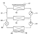
- the vehicle refrigeration cycle apparatus 10 shown in FIG. 1 constitutes a vehicle air conditioner that adjusts the interior of the vehicle to an appropriate temperature.
- the vehicle refrigeration cycle apparatus 10 is applied to a hybrid vehicle that obtains driving force for vehicle travel from an engine (internal combustion engine) and a travel electric motor.
- the hybrid vehicle according to the present embodiment is configured as a plug-in hybrid vehicle that can charge power supplied from an external power source (commercial power source) when the vehicle is stopped to a battery (vehicle battery) mounted on the vehicle.
- a battery vehicle battery
- the battery for example, a lithium ion battery can be used.
- the driving force output from the engine is used not only for driving the vehicle but also for operating the generator.
- the electric power generated by the generator and the electric power supplied from the external power source can be stored in the battery, and the electric power stored in the battery constitutes the vehicle refrigeration cycle apparatus 10 as well as the electric motor for traveling. It is supplied to various in-vehicle devices such as electric components.
- the refrigeration cycle apparatus 10 for a vehicle includes a first pump 11, a second pump 12, a radiator 13, a cooling water cooler 14, a cooling water heater 15, and a cooler core 16.
- the first pump 11 and the second pump 12 are pumps for sucking and discharging cooling water, and are constituted by electric pumps, for example.
- the cooling water is a fluid as a heat medium.
- a liquid containing at least ethylene glycol, dimethylpolysiloxane or nanofluid, or an antifreeze liquid is used as the cooling water.
- the radiator 13, the cooling water cooler 14, the cooling water heater 15 and the cooler core 16 are cooling water distribution devices (heat medium distribution devices) through which the cooling water flows.
- the radiator 13 is a cooling water outside air heat exchanger (heat medium outside air heat exchanger) that exchanges heat between cooling water and outside air (air outside the passenger compartment). Outside air is blown to the radiator 13 by the outdoor blower 17.
- heat medium outside air heat exchanger heat medium outside air heat exchanger
- the outdoor blower 17 is an outside air blower (blower) that blows outside air to the radiator 13.
- the outdoor blower 17 is an electric blower that drives a blower fan with an electric motor (blower motor).
- the radiator 13 and the outdoor blower 17 are arranged at the forefront of the vehicle. For this reason, the traveling wind can be applied to the radiator 13 when the vehicle is traveling.
- the radiator 13 functions as a heat dissipation heat exchanger that dissipates the heat of the cooling water to the outside air.
- the radiator 13 functions as an endothermic heat exchanger that causes the cooling water to absorb the heat of the outside air.
- the cooling water cooler 14 is a low pressure side heat exchanger (heat medium cooler) that cools the cooling water by exchanging heat between the low pressure side refrigerant of the refrigerant circuit 20 (refrigeration cycle) and the cooling water.
- the cooling water cooler 14 can cool the cooling water to a temperature lower than the temperature of the outside air.
- the cooling water heater 15 is a high pressure side heat exchanger (heat medium heater) that heats the cooling water by exchanging heat between the high pressure side refrigerant of the refrigerant circuit 20 and the cooling water.
- the cooling water heater 15 can heat the cooling water to a temperature higher than the temperature of the outside air.
- the refrigerant circuit 20 is a vapor compression refrigerator that includes a compressor 21, a cooling water heater 15, an expansion valve 22, and a cooling water cooler 14.
- a chlorofluorocarbon refrigerant is used as the refrigerant, and a subcritical refrigeration cycle in which the high-pressure side refrigerant pressure does not exceed the critical pressure of the refrigerant is configured.
- the compressor 21 is an electric compressor driven by electric power supplied from a battery or a variable capacity compressor driven by a belt, and sucks, compresses and discharges the refrigerant in the refrigerant circuit 20.
- the cooling water heater 15 is a condenser that condenses the high pressure side refrigerant by exchanging heat between the high pressure side refrigerant discharged from the compressor 21 and the cooling water.
- the expansion valve 22 is a decompressor that decompresses and expands the liquid refrigerant flowing out of the cooling water heater 15.
- the cooling water cooler 14 is an evaporator that evaporates the low-pressure refrigerant by exchanging heat between the low-pressure refrigerant decompressed and expanded by the expansion valve 22 and the cooling water.
- the gas-phase refrigerant evaporated in the cooling water cooler 14 is sucked into the compressor 21 and compressed.
- the cooler core 16 is a cooling air heat exchanger that cools the air blown into the vehicle interior by exchanging heat between the cooling water and the air blown into the vehicle interior.
- the cooler core 16 is an air cooling heat exchanger that cools air using at least a part of the heat quantity of the refrigerant discharged from the compressor 21.
- the cooling water cooler 14 and the cooler core 16 are air coolers that cool the air blown into the vehicle interior using the cold heat of the low-pressure refrigerant decompressed by the expansion valve 22.
- the cooler core 16 is blown by the indoor blower 18 with the inside air (vehicle interior air), the outside air, or the mixed air of the inside air and the outside air.
- the indoor blower 18 is a blower (blower) that generates air flowing toward the vehicle interior.
- the indoor blower 18 is an electric blower that drives a centrifugal multiblade fan (sirocco fan) with an electric motor (blower motor).
- the indoor blower 18 is an air flow rate adjusting unit that adjusts the flow rate of air passing through the cooler core 16.
- the cooler core 16 and the indoor blower 18 are accommodated in a casing 31 of the indoor air conditioning unit 30.
- the indoor air conditioning unit 30 is disposed inside the instrument panel (instrument panel) at the forefront of the vehicle interior.
- the casing 31 forms the outer shell of the indoor air conditioning unit.
- the casing 31 forms an air passage through which air blown into the passenger compartment flows, and is formed of a resin (for example, polypropylene) having a certain degree of elasticity and excellent strength.
- a resin for example, polypropylene
- a heater core air heater
- an air mix door may be arranged on the downstream side of the air flow from the cooler core 16.
- the heater core is a heating heat exchanger (air heater) that heats the air blown into the passenger compartment.
- the heater core heats the air blown into the vehicle interior using the high-pressure side refrigerant (high-temperature refrigerant) of the refrigerant circuit 20, engine cooling water (hot water), or the like as a heat source.
- the air mix door adjusts the ratio of the flow rate of the air flowing through the heater core and the flow rate of the air flowing bypassing the heater core to adjust the temperature of the blown air blown into the passenger compartment (air flow rate) Ratio adjustment unit).
- the first pump 11, the radiator 13, and the cooling water heater 15 are disposed in the first cooling water circuit C1 (first heat medium circuit).
- the first cooling water circuit C ⁇ b> 1 is configured so that the cooling water circulates in the order of the first pump 11, the radiator 13, the cooling water heater 15, and the first pump 11.
- the second pump 12, the cooling water cooler 14, and the cooler core 16 are disposed in the second cooling water circuit C2 (second heat medium circuit).
- the second cooling water circuit C ⁇ b> 2 is configured so that the cooling water circulates in the order of the second pump 12, the cooling water cooler 14, the cooler core 16, and the second pump 12.
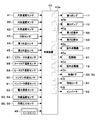
- the control device 40 shown in FIG. 2 includes a known microcomputer including a CPU, a ROM, a RAM, and the like and peripheral circuits thereof.
- the control device 40 performs various calculations and processes based on the air conditioning control program stored in the ROM, and the first pump 11, the second pump 12, the outdoor blower 17, the indoor blower 18, and the compression connected to the output side. It is a control part which controls operation
- the control device 40 is supplied with electric power from the vehicle battery.
- the control device 40 is configured such that a control unit that controls various devices to be controlled connected to the output side is integrally configured.
- the configuration (hardware and software) that controls the operation of each control target device constitutes a control unit that controls the operation of each control target device.
- operation of the 1st pump 11 among the control apparatuses 40 comprises the 1st cooling water flow control part 40a (1st heat medium flow control part).
- the structure (hardware and software) which controls operation of the 2nd pump 12 among control devices 40 constitutes the 2nd cooling water flow control part 40b (2nd heat carrier flow control part).
- operation of the outdoor air blower 17 among the control apparatuses 40 comprises the outdoor air blower control part 40c.
- operation of the indoor air blower 18 among the control apparatuses 40 comprises the indoor air blower control part 40d.
- operation of the compressor 21 among the control apparatuses 40 comprises the refrigerant
- coolant flow control part 40e are comprised separately with respect to the control apparatus 40. Also good.
- detection signals of sensor groups such as the inside air sensor 41, the outside air sensor 42, the solar radiation sensor 43, the first water temperature sensor 44, the second water temperature sensor 45, the refrigerant temperature sensor 46, the refrigerant pressure sensor 47, and the like. Entered.
- the inside air sensor 41 is a detector (inside air temperature detector) that detects the inside air temperature (in-vehicle temperature).
- the outside air sensor 42 is a detector (outside air temperature detector) that detects an outside air temperature (a temperature outside the passenger compartment).
- the solar radiation sensor 43 is a detector (a solar radiation amount detector) that detects the amount of solar radiation in the passenger compartment.
- the first water temperature sensor 44 is a detector (first heat medium temperature detector) that detects the temperature of the cooling water flowing through the first cooling water circuit C1 (for example, the temperature of the cooling water flowing out from the cooling water heater 15). .
- the second water temperature sensor 45 is a detector (second heat medium temperature detector) that detects the temperature of the cooling water flowing through the second cooling water circuit C2 (for example, the temperature of the cooling water flowing out from the cooling water cooler 14). .
- the refrigerant temperature sensor 46 is a detector (refrigerant temperature detector) that detects the refrigerant temperature of the refrigerant circuit 20.
- the refrigerant temperature of the refrigerant circuit 20 detected by the refrigerant temperature sensor 46 is, for example, the temperature of the high-pressure refrigerant discharged from the compressor 21, the temperature of the low-pressure refrigerant sucked into the compressor 21, or the low-pressure refrigerant decompressed and expanded by the expansion valve 22. And the temperature of the low-pressure refrigerant heat-exchanged by the cooling water cooler 14.
- the refrigerant pressure sensor 47 is a detector (refrigerant pressure detector) that detects the refrigerant pressure of the refrigerant circuit 20 (for example, the pressure of high-pressure refrigerant discharged from the compressor 21 or the pressure of low-pressure refrigerant sucked into the compressor 21). It is.
- the inside air temperature, outside air temperature, cooling water temperature, refrigerant temperature, and refrigerant pressure may be estimated based on detection values of various physical quantities.
- the temperature of the cooling water in the first cooling water circuit C ⁇ b> 1 is set to the outlet refrigerant pressure of the cooling water heater 15, the discharge refrigerant pressure of the compressor 21, the pressure of the high-pressure side refrigerant of the refrigerant circuit 20, and the high-pressure side refrigerant of the refrigerant circuit 20. May be calculated based on at least one of the following temperature, the temperature of the heat exchange fin of the radiator 13, the temperature of the heat exchange fin of the cooling water heater 15, and the like.
- the temperature of the cooling water in the second cooling water circuit C ⁇ b> 2 may be the outlet refrigerant pressure of the cooling water cooler 14, the suction refrigerant pressure of the compressor 21, the pressure of the low-pressure side refrigerant of the refrigerant circuit 20, the low-pressure side refrigerant of the refrigerant circuit 20. May be calculated based on at least one of the temperature, the temperature of the heat exchange fins of the cooler core 16, the temperature of the heat exchange fins of the cooling water cooler 14, and the like.
- An operation signal from the operation panel 48 is input to the input side of the control device 40.
- the operation panel 48 is disposed near the instrument panel in the vehicle interior, and the operation panel 48 is provided with various operation switches. As various operation switches provided on the operation panel 48, an air conditioning operation switch, a passenger compartment temperature setting switch, and the like are provided.
- the air conditioning operation switch is a switch for an occupant to request air conditioning in the vehicle interior, and outputs an air conditioning request signal (that is, a compressor activation request signal) to the control device 40.
- the vehicle interior temperature setting switch is a switch for setting the vehicle interior temperature desired by the passenger.
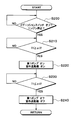
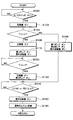
- FIG. 3 is a flowchart showing an outline of the control process executed by the control device 40.
- the control device 40 starts executing this control process when the ignition switch of the vehicle is turned on.
- the process proceeds to S130, and the compressor 21 and the second pump 12 are activated. Thereby, the cooling water of the second cooling water circuit C2 is cooled by the cooling water cooler 14.
- the cooling water heater 15 since the cooling water of the first cooling water circuit C1 cooled to the first predetermined value ⁇ 1 or less exchanges heat with the refrigerant, the refrigerant temperature and pressure are prevented from excessively rising. it can.
- the temperature T1 of the cooling water in the first cooling water circuit C1 is equal to or lower than the first predetermined value ⁇ 1. You may make it estimate whether it is.
- subsequent S140 it is determined whether or not the temperature T2 of the cooling water in the second cooling water circuit C2 (second circuit) is equal to or lower than the second predetermined value ⁇ 2. In other words, it is estimated whether the temperature or pressure of the low-pressure side refrigerant (low-pressure refrigerant) in the refrigerant circuit 20 is equal to or less than a predetermined value.
- the process proceeds to S150, and the indoor blower 18 is activated. Thereby, the air blown into the passenger compartment by the cooler core 16 is cooled.
- S140 it is determined whether or not the temperature of the low-pressure side refrigerant (low-pressure refrigerant) in the refrigerant circuit 20 is equal to or lower than the second predetermined value ⁇ 2, and the temperature T2 of the low-pressure side refrigerant in the refrigerant circuit 20 is equal to or lower than the second predetermined value ⁇ 2. If it is determined that there is, the process of S140 is repeated, and if it is determined that the temperature T2 of the low-pressure side refrigerant of the refrigerant circuit 20 is equal to or lower than the second predetermined value ⁇ 2, the process may proceed to S150.
- the refrigerant discharge capacity of the compressor 21 and the air blowing capacity of the indoor blower 18 may be controlled based on the target blowing temperature TAO or the like.
- the target blowing temperature TAO is calculated by the following formula.
- TAO Kset ⁇ Tset ⁇ Kr ⁇ Tr ⁇ Kam ⁇ Tam ⁇ Ks ⁇ Ts + C
- Tset is the vehicle interior temperature set by the vehicle interior temperature setting switch
- Tr is the vehicle interior temperature (internal air temperature) detected by the internal air sensor 41
- Tam is the external air temperature detected by the external air sensor 42
- Ts is the solar radiation sensor 43. Is the amount of solar radiation detected by.
- Kset, Kr, Kam, Ks are control gains
- C is a correction constant.
- the control device 40 activates the first pump 11 when there is a request for activation of the compressor 21. After starting the 1st pump 11, the control apparatus 40 starts the compressor 21, when it determines or estimates that the temperature T1 of the cooling water of the 1st cooling water circuit C1 is below 1st predetermined value (alpha) 1.
- the radiator 13 exchanges heat between the cooling water of the first cooling water circuit C1 and the outside air, and the first cooling water circuit C1.
- the cooling water can be cooled.
- the compressor 21 When it is determined or estimated that the temperature T1 of the cooling water in the first cooling water circuit C1 is equal to or lower than the first predetermined value ⁇ 1, the compressor 21 is started. Thereby, in the cooling water heater 15, the cooling water of the 1st cooling water circuit C1 cooled to some extent with the radiator 13 is heat-exchanged with a refrigerant
- the control device 40 sets the temperature T2 of the cooling water in the second cooling water circuit C2 (in other words, the temperature TR2 or the pressure PR2 of the low-pressure refrigerant) to the second predetermined value ⁇ 2. If it is determined or estimated to be the following, the indoor blower 18 is activated.
- the indoor blower 18 since the indoor blower 18 is started after the low-pressure refrigerant is lowered to some extent, when the indoor blower 18 is started, the cooling water of the second cooling water circuit C2 cooled to some extent by the cooling water cooler 14 is used. However, the air blown into the passenger compartment by the cooler core 16 is cooled to some extent. Therefore, it can suppress that the warm air which is hardly cooled is blown into the vehicle interior and becomes uncomfortable for the passenger.
- the low-pressure refrigerant decompressed by the expansion valve 22 and the cooling water in the second cooling water circuit C2 are heat-exchanged to cool the cooling water in the second cooling water circuit C2.
- the cooler core 16 heat-exchanges the cooling water of the 2nd cooling water circuit C2 cooled with the cooling water cooler 14, and the air ventilated into a vehicle interior, and cools the air ventilated into a vehicle interior.
- the heat capacity of the cooling water of the 2nd cooling water circuit C2 is large, it can suppress that the cooling temperature of the air in the cooler core 16 fluctuates rapidly. Therefore, it can suppress that the cooling temperature of the air in the cooler core 16 falls rapidly, and frost adheres to the cooler core 16. Moreover, in order to suppress that frost adheres to the cooler core 16, it can suppress that the frost suppression control of stopping the compressor 21 is performed.
- the first pump 11 when the A / C switch is turned on, the first pump 11 is activated to cool the cooling water in the first cooling water circuit C1.
- the first pump 11 is started and the first Cooling water in the cooling water circuit C1 is cooled.
- FIG. 4 is a flowchart showing an outline of control processing executed by the control device 40.
- electric power is supplied to the control device 40 from the battery of the vehicle regardless of the on / off state of the ignition switch of the vehicle.
- the control device 40 starts executing this control process regardless of whether the ignition switch of the vehicle is on or off.
- S200 it is determined whether or not it is at least one of a state where the ignition switch of the vehicle is turned off and a state where the vehicle engine is stopped. That is, it is determined whether or not the vehicle is parked.
- the temperature T1 of the cooling water in the first cooling water circuit C1 is a third predetermined value. You may make it estimate whether it is more than (alpha) 3.
- the fourth predetermined value ⁇ 4 is a value smaller than the third predetermined value ⁇ 3.
- the temperature T1 of the cooling water in the first cooling water circuit C1 is a fourth predetermined value. You may make it estimate whether it is below (alpha) 4.
- the control device 40 cools the first cooling water circuit C1 in the state where at least one of the state where the ignition switch of the vehicle is turned off and the state where the engine of the vehicle is stopped.
- the first pump 11 is activated.
- the control device 40 determines or estimates that the temperature T1 of the cooling water in the first cooling water circuit C1 is equal to or lower than the fourth predetermined value ⁇ 4, which is smaller than the third predetermined value ⁇ 3, after starting the first pump 11. Then, the first pump 11 is stopped.
- the temperature T1 of the cooling water in the first cooling water circuit C1 rises excessively when the ignition switch of the vehicle is turned off or when the engine of the vehicle is stopped. Can be suppressed. Therefore, after the ignition switch of the vehicle is turned on or after the engine of the vehicle is started, the compressor 21 can be quickly started to start air conditioning.
- the control device 40 sets the temperature T1 of the cooling water in the first cooling water circuit C1, When one physical quantity of the refrigerant temperature and the refrigerant pressure is determined or estimated to be equal to or greater than the third predetermined value ⁇ 3, the first pump 11 is activated. Subsequently, after starting the first pump 11, the control device 40 has a physical quantity of one of the cooling water temperature T1, the refrigerant temperature, and the refrigerant pressure in the first cooling water circuit C1 from the third predetermined value ⁇ 3.
- the second cooling water circuit C2 is provided.
- the second cooling water circuit C2 is not provided, and an evaporator is used instead of the cooling water cooler 14. 40.
- the evaporator 40 is a cooling water air heat exchanger that performs heat exchange between the low-pressure refrigerant decompressed and expanded by the expansion valve 22 and the air blown into the vehicle cabin to cool the air blown into the vehicle cabin.
- the evaporator 40 is an air cooler that cools the air blown into the vehicle interior using the cold heat of the low-pressure refrigerant decompressed by the expansion valve 22.
- the interior air (vehicle interior air), the outside air, or a mixed air of the inside air and the outside air is blown to the evaporator 40 by the indoor blower 18.
- FIG. 6 is a flowchart showing an outline of the control process executed by the control device 40.
- S300 it is determined whether or not the ignition switch of the vehicle is turned on and the vehicle engine is turned on. That is, it is determined whether or not the vehicle is running.
- the process proceeds to S310, and the operation panel 48 It is determined whether or not the provided A / C switch is in an off state. In other words, it is determined whether or not there is a request for starting the compressor 21.
- the temperature T1 of the cooling water in the first cooling water circuit C1 is a fifth predetermined value. You may make it estimate whether it is more than (alpha) 5.
- the temperature T1 of the cooling water in the first cooling water circuit C1 is the fifth predetermined value ⁇ 5 in a state where the ignition switch of the vehicle is turned on, the engine of the vehicle is operating, and the compressor 21 is stopped.
- the first pump 11 is started.
- the vehicle refrigeration cycle apparatus 10 comprises the vehicle air conditioner.
- the vehicle refrigeration cycle apparatus 10 may constitute a vehicle thermal management system that adjusts various devices included in the vehicle to an appropriate temperature.
- first cooling water circuit C1 and the second cooling water circuit C2 may be connected via a switching valve.
- the switching valve has cooling water sucked and discharged by the first pump 11 for each of the plurality of heat medium circulation devices arranged in the first cooling water circuit C1 and the second cooling water circuit C2. Switching between circulating and cooling water sucked and discharged by the second pump 12 is switched.
- the heat management system 10 of the present embodiment includes a heater core 51, an inverter 52, a battery temperature adjustment heat exchanger 53, a cooling water cooling water heat exchanger 54, and a first switching valve 55. And a second switching valve 56 is provided.
- the heater core 51 is a cooling water distribution device (heat medium distribution device) through which cooling water flows.
- the heater core 51 is an air heating heat exchanger (heat medium air heat exchanger) that heat-exchanges cooling air and air blown into the vehicle interior to heat the air blown into the vehicle interior.
- the cooling water absorbs heat from the air by sensible heat change. That is, in the cooler core 16, even if the cooling water absorbs heat from the air, the cooling water remains in a liquid phase and does not change in phase.
- Inside air, outside air, or mixed air of inside air and outside air is blown to the cooler core 16 by the indoor blower 18.
- the inverter 52, the battery temperature adjustment heat exchanger 53, and the cooling water cooling water heat exchanger 54 have a flow path through which the cooling water flows, and are a heat transfer device (a temperature adjustment target) that exchanges heat with the cooling water.
- the inverter 52 is a power conversion device that converts DC power supplied from the battery into AC voltage and outputs the AC voltage to the traveling electric motor.
- the inverter 52 is a heat generating device that generates heat when activated.
- the battery temperature control heat exchanger 53 is a heat exchanger that exchanges heat between the battery and the cooling water.
- the battery temperature adjustment heat exchanger 53 is a heat exchanger that is disposed in contact with the battery and conducts heat with the battery.
- the battery temperature adjustment heat exchanger 53 may be a heat exchanger (air heat medium heat exchanger) that is disposed in the air blowing path to the battery and exchanges heat between the air and the cooling water.
- the cooling water cooling water heat exchanger 54 includes cooling water (cooling water circulated by the first pump 11 or the second pump 12) of the vehicle thermal management system 10 and cooling water (engine heat medium for the engine cooling circuit 70). ) And a heat exchanger (heat medium heat medium heat exchanger).
- the first pump 11 is disposed in the first pump flow path 61.
- the cooling water cooling heat exchanger 14 is disposed on the discharge side of the first pump 11 in the first pump flow path 61.
- the second pump 12 is disposed in the second pump flow path 62.
- a cooling water heating heat exchanger 15 is disposed on the discharge side of the second pump 12 in the second pump flow path 62.
- the outdoor heat exchanger 13 is disposed in the outdoor heat exchanger flow path 63.
- the cooler core 16 is disposed in the cooler core flow path 64.
- the heater core 51 is disposed in the heater core flow path 65.
- the inverter 52 is disposed in the inverter flow path 66.
- the battery temperature adjustment heat exchanger 53 is disposed in the battery temperature adjustment flow path 67.
- the cooling water cooling water heat exchanger 54 is disposed in the cooling water cooling water heat exchanger flow path 68.
- the water cooling water heat exchanger flow path 68 is connected to the first switching valve 55 and the second switching valve 56.
- the first switching valve 55 and the second switching valve 56 are switching units that switch the flow of cooling water.
- the first switching valve 55 has a first inlet 55a and a second inlet 55b as cooling water inlets.
- the first switching valve 55 further includes a first outlet 55c, a second outlet 55d, a third outlet 55e, a fourth outlet 55f, a fifth outlet 55g, a sixth outlet 55h, and a seventh outlet 55i as cooling water outlets. ing.
- the second switching valve 56 has a first outlet 56a and a second outlet 56b as outlets for cooling water.
- the second switching valve 56 further includes a first inlet 56c, a second inlet 56d, a third inlet 56e, a fourth inlet 56f, a fifth inlet 56g, a sixth inlet 56h, and a seventh inlet 56i as cooling water inlets. ing.
- One end of the first pump flow path 61 is connected to the first inlet 55a of the first switching valve 55.
- the cooling water outlet side of the cooling water cooling heat exchanger 14 is connected to the first inlet 55 a of the first switching valve 55.
- One end of the second pump flow path 62 is connected to the second inlet 55b of the first switching valve 55.
- the cooling water outlet side of the cooling water heating heat exchanger 15 is connected to the second inlet 55 b of the first switching valve 55.
- One end of the outdoor heat exchanger channel 63 is connected to the first outlet 55 c of the first switching valve 55.
- the cooling water inlet side of the outdoor heat exchanger 13 is connected to the first outlet 55 c of the first switching valve 55.
- One end of a cooler core flow path 64 is connected to the second outlet 55d of the first switching valve 55.
- the cooling water inlet side of the cooler core 16 is connected to the second outlet 55 d of the first switching valve 55.
- One end of a heater core flow path 65 is connected to the third outlet 55e of the first switching valve 55.
- the cooling water inlet side of the heater core 51 is connected to the third outlet 55 e of the first switching valve 55.
- One end of the cooling water / cooling water heat exchanger flow path 68 is connected to the fourth outlet 55f of the first switching valve 55.
- the cooling water inlet side of the cooling water cooling water heat exchanger 54 is connected to the fourth outlet 55 f of the first switching valve 55.
- One end of a battery temperature adjusting flow path 67 is connected to the fifth outlet 55g of the first switching valve 55.
- the cooling water inlet side of the battery temperature adjusting heat exchanger 53 is connected to the fifth outlet 55g of the first switching valve 55.
- One end of the inverter flow channel 66 is connected to the sixth outlet 55h of the first switching valve 55.
- the cooling water inlet side of the inverter 52 is connected to the sixth outlet 55 h of the first switching valve 55.
- the bypass channel 26 is a channel through which the cooling water flows by bypassing each of the cooling water circulation devices 13, 16, 51, 52, 53, 54.
- the other end of the first pump flow path 61 is connected to the first outlet 56 a of the second switching valve 56.
- the cooling water suction side of the first pump 11 is connected to the first outlet 56 a of the second switching valve 56.
- the other end of the second pump flow path 62 is connected to the second outlet 56 b of the second switching valve 56.
- the cooling water suction side of the second pump 12 is connected to the second outlet 56 b of the second switching valve 56.
- the other end of the outdoor heat exchanger channel 63 is connected to the first inlet 56 c of the second switching valve 56.
- the cooling water outlet side of the outdoor heat exchanger 13 is connected to the first inlet 56 c of the second switching valve 56.
- the other end of the cooler core channel 64 is connected to the second inlet 56d of the second switching valve 56.
- the cooling water outlet side of the cooler core 16 is connected to the second inlet 56 d of the second switching valve 56.
- the other end of the heater core flow path 65 is connected to the third inlet 56e of the second switching valve 56.
- the coolant outlet side of the heater core 51 is connected to the third inlet 56 e of the second switching valve 56.
- the other end of the cooling water / cooling water heat exchanger channel 68 is connected to the fourth inlet 56f of the second switching valve 56.
- the cooling water outlet side of the cooling water cooling water heat exchanger 54 is connected to the fourth inlet 56 f of the second switching valve 56.
- the other end of the battery temperature adjusting flow path 67 is connected to the fifth inlet 56g of the second switching valve 56.
- the cooling water outlet side of the battery temperature adjusting heat exchanger 53 is connected to the fifth inlet 56 g of the second switching valve 56.
- the other end of the inverter flow channel 66 is connected to the sixth inlet 56h of the second switching valve 56.
- the cooling water outlet side of the inverter 52 is connected to the sixth inlet 56 h of the second switching valve 56.
- the other end of the bypass flow path 26 is connected to the seventh inlet 56i of the second switching valve 56.
- the first switching valve 55 and the second switching valve 56 have a structure capable of arbitrarily or selectively switching the communication state between each inlet and each outlet.
- the first switching valve 55 includes the outdoor heat exchanger 13, the cooler core 16, the heater core 51, the inverter 52, the battery temperature adjustment heat exchanger 53, the cooling water / cooling water heat exchanger 54, and the bypass passage 26.
- the outdoor heat exchanger 13 the cooler core 16, the heater core 51, the inverter 52, the battery temperature adjustment heat exchanger 53, the cooling water / cooling water heat exchanger 54, and the bypass passage 26.
- the second switching valve 56 is a first pump for each of the outdoor heat exchanger 13, the cooler core 16, the heater core 51, the inverter 52, the battery temperature adjustment heat exchanger 53, the cooling water cooling water heat exchanger 54, and the bypass passage 26. 11 is switched between a state in which the cooling water flows out to 11, a state in which the cooling water flows out to the second pump 12, and a state in which the cooling water does not flow out to the first pump 11 and the second pump 12.
- the valve opening degree of the first switching valve 55 and the second switching valve 56 can be adjusted. Thereby, the flow volume of the cooling water which flows through the outdoor heat exchanger 13, the cooler core 16, the heater core 51, the inverter 52, the heat exchanger 53 for battery temperature control, the cooling water cooling water heat exchanger 54, and the bypass flow path 26 can be adjusted.
- the first switching valve 55 and the second switching valve 56 are flow rate adjustment valves that adjust the flow rate of the cooling water flowing through each of the cooling water circulation devices 13, 16, 51, 52, 53, 54 and the bypass flow path 26. .
- the 1st switching valve 55 and the 2nd switching valve 56 mix the cooling water discharged from the 1st pump 11, and the cooling water discharged from the 2nd pump 12 in arbitrary flow rate ratios, and are an outdoor heat exchanger. 13, the cooler core 16, the heater core 51, the inverter 52, the battery temperature adjusting heat exchanger 53, the cooling water / cooling water heat exchanger 54, and the bypass channel 26.
- the cooler core 16 and the heater core 51 are accommodated in the casing 31 of the indoor air conditioning unit 30 of the vehicle air conditioner.
- An inside / outside air switching box 32 is arranged on the most upstream side of the air flow in the casing 31.
- the inside / outside air switching box 32 is an inside / outside air introduction section that switches between and introduces inside air (vehicle compartment air) and outside air (vehicle compartment outside air).
- the inside / outside air switching box 32 is formed with an inside air inlet 32 a for introducing inside air into the casing 31 and an outside air inlet 32 b for introducing outside air.
- An inside / outside air switching door 33 is arranged inside the inside / outside air switching box 32.
- the inside / outside air switching door 33 is an air volume ratio changing unit that changes the air volume ratio between the inside air and the outside air introduced into the casing 31. Specifically, the inside / outside air switching door 33 continuously adjusts the opening areas of the inside air suction port 32a and the outside air suction port 32b to change the air volume ratio between the air volume of the inside air and the air volume of the outside air.
- the inside / outside air switching door 33 is driven by an electric actuator (not shown).
- the indoor blower 18 (blower) is disposed on the downstream side of the air flow in the inside / outside air switching box 32.
- the indoor blower 18 is a blower that blows air (inside air and outside air) sucked through the inside / outside air switching box 32 toward the vehicle interior.
- the cooler core 16 and the heater core 51 are arranged on the downstream side of the air flow of the indoor blower 18.
- a heater core bypass passage 31a is formed at the downstream side of the air flow of the cooler core 16.
- the heater core bypass passage 31 a is an air passage through which air that has passed through the cooler core 16 flows without passing through the heater core 51.
- An air mix door 35 is disposed between the cooler core 16 and the heater core 51 inside the casing 31.
- the air mix door 35 is an air volume ratio adjusting unit that continuously changes the air volume ratio between the air flowing into the heater core 51 and the air flowing into the heater core bypass passage 31a.
- the air mix door 35 is a rotatable plate-like door, a slidable door, or the like, and is driven by an electric actuator (not shown).
- the air mix door 35 is a temperature adjusting unit that adjusts the temperature of the air blown into the vehicle interior.
- the blower outlet 31b which blows off air to the vehicle interior which is air-conditioning object space is arrange
- the defroster outlet blows air conditioned air toward the inner surface of the front window glass of the vehicle.
- the face air outlet blows conditioned air toward the upper body of the passenger.
- the air outlet blows air-conditioned air toward the passenger's feet.
- An air outlet mode door (not shown) is arranged on the air flow upstream side of the air outlet 31b.
- a blower outlet mode door is a blower outlet mode switching part which switches blower outlet mode.
- the air outlet mode door is driven by an electric actuator (not shown).
- the outlet mode switched by the outlet mode door for example, there are a face mode, a bi-level mode, a foot mode, and a foot defroster mode.
- the face mode is a blowout mode in which the face blowout is fully opened and air is blown out from the face blowout toward the upper body of the passenger in the passenger compartment.
- the bi-level mode is an air outlet mode in which both the face air outlet and the foot air outlet are opened and air is blown toward the upper body and the feet of the passengers in the passenger compartment.
- the foot mode is a blowout mode in which the foot blowout opening is fully opened and the defroster blowout opening is opened by a small opening so that air is mainly blown out from the foot blowout opening.
- the foot defroster mode is an air outlet mode in which the foot air outlet and the defroster air outlet are opened to the same extent and air is blown out from both the foot air outlet and the defroster air outlet.
- the engine cooling circuit 70 is a cooling water circulation circuit for cooling the engine 71.
- the engine cooling circuit 70 has a circulation channel 72 through which engine coolant (second heat medium) circulates.
- engine coolant second heat medium
- an engine 71, a third pump 73, an engine radiator 74, and a cooling water / cooling water heat exchanger 54 are disposed.
- the third pump 73 is an electric pump that sucks and discharges engine coolant.
- the third pump 73 may be a mechanical pump driven by power output from the engine 71.
- the engine radiator 74 is a heat exchanger (air heat medium heat exchanger) for radiating heat to dissipate the heat of the cooling water to the outside air by exchanging heat between the engine cooling water and the outside air.
- a radiator bypass channel 75 is connected to the circulation channel 72.
- the radiator bypass channel 75 is a channel through which engine coolant flows bypassing the engine radiator 74.
- a thermostat 76 is disposed at a connection portion between the radiator bypass passage 75 and the circulation passage 72.
- the thermostat 76 is a cooling water temperature responsive valve configured by a mechanical mechanism that opens and closes the cooling water flow path by displacing the valve body by a thermo wax (temperature sensitive member) that changes in volume according to temperature.
- the thermostat 76 closes the radiator bypass passage 75 when the temperature of the engine cooling water is higher than a predetermined temperature (for example, 80 ° C. or higher), and the temperature of the cooling water is lower than the predetermined temperature ( For example, the radiator bypass channel 75 is opened.
- a predetermined temperature for example, 80 ° C. or higher
- the circulation passage 72 is connected to an engine accessory passage 77.
- the engine auxiliary passage 77 is a passage through which engine coolant flows in parallel with the coolant coolant heat exchanger 54.
- An engine accessory 78 is disposed in the engine accessory channel 77.
- the cooling water cooling water heat exchanger 54 may be disposed in the cooling engine auxiliary machine flow path 77 so that the cooling water flows in series with the engine auxiliary machine 78.
- the engine auxiliary machine 78 is an oil heat exchanger, an EGR cooler, a throttle cooler (warmer), a turbo cooler, an engine auxiliary motor, or the like.
- the oil heat exchanger is a heat exchanger that adjusts the temperature of oil by exchanging heat between engine oil or transmission oil and engine coolant.
- the EGR cooler is a heat exchanger that constitutes an EGR (exhaust gas recirculation) device that recirculates a part of the exhaust gas of the engine to the intake side to reduce the pumping loss generated by the throttle valve.
- the EGR cooler adjusts the temperature of the reflux gas by exchanging heat between the reflux gas and the engine coolant.
- the throttle cooler (warmer) is a water jacket provided inside the throttle to cool (heat) the throttle valve.
- the turbo cooler is a cooler for cooling the turbocharger by exchanging heat between the heat generated in the turbocharger and the engine coolant.
- the engine auxiliary motor is a large motor that allows the engine belt to rotate even when the engine is stopped.
- the engine auxiliary motor operates a compressor or a water pump driven by an engine belt even when there is no driving force of the engine 71 or is used when the engine 71 is started.
- An engine reserve tank 79 is connected to the engine radiator 74.
- the engine reserve tank 79 is an open-air container (heat medium storage unit) that stores engine cooling water. Therefore, the pressure at the liquid level of the engine coolant stored in the engine reserve tank 79 becomes atmospheric pressure.
- the engine reserve tank 79 may be configured such that the pressure at the liquid level of the engine coolant stored in the engine reserve tank 79 is a predetermined pressure (a pressure different from the atmospheric pressure).
- the engine reserve tank 79 has a function of gas-liquid separation of bubbles mixed in the engine coolant.
- a reserve tank 80 is connected to the outdoor heat exchanger channel 63.
- the structure and function of the reserve tank 80 are the same as those of the engine reserve tank 79.
- Auxiliary heater 81 is arranged at the downstream side of the air flow of heater core 51 inside casing 31 of indoor air conditioning unit 30.
- the auxiliary heater 81 is an air heater that heats air.
- the auxiliary heater 81 has a PTC element (positive characteristic thermistor) and is a PTC heater (electric heater) that generates heat and heats air when electric power is supplied to the PTC element.
- the auxiliary heater 81 may have a heating wire such as a nichrome wire and may be a heating heater of a type that heats air by supplying power to the heating wire.
- movement of the 1st switching valve 55 and the 2nd switching valve 56 among the control apparatuses 40 comprises the switching valve control part 40g (flow regulating valve control part).
- the switching valve control unit 40g may be configured separately from the control device 40.
- the switching valve control unit 40g controls the flow rate of the cooling water flowing through each of the cooling water circulation devices 13, 16, 51, 52, 53, 54 and the bypass flow path 26 together with the first switching valve 55 and the second switching valve 56.
- a cooling water flow rate control unit (heat medium flow rate control unit) is configured.
- control device 40 the configuration (hardware and software) for controlling the operation of various doors (inside / outside air switching door 33, air mix door 35, outlet mode door, etc.) arranged inside the casing 31 is air conditioning switching.
- the control unit 40h is configured.
- the air conditioning switching control unit 40h may be configured separately from the control device 40.
- the air mix door 35 and the air conditioning switching control unit 40h are an air volume ratio adjusting unit that adjusts an air volume ratio between air flowing through the heater core 51 and air flowing around the heater core 51 out of the air cooled by the cooler core 16.
- the inside / outside air switching door 33 and the air conditioning switching control unit 40h are an inside / outside air ratio adjusting unit that adjusts the ratio of the inside air to the outside air in the air blown into the vehicle interior.
- the configuration (hardware and software) for controlling the operation of the auxiliary heater 81 (specifically, the auxiliary heater relay 83) in the control device 40 constitutes an auxiliary heater control unit 40i (electric heater control unit).
- the auxiliary heater control unit 40 i is an air heating control unit that controls heating of air by the auxiliary heater 81.
- the configuration (hardware and software) for controlling the operation of the inverter 52 in the control device 40 constitutes an inverter control unit 40j.
- an inside air temperature sensor 41 On the input side of the control device 40, an inside air temperature sensor 41, an inside air humidity sensor 85, an outside air temperature sensor 42, a solar radiation sensor 43, a first water temperature sensor 44, a second water temperature sensor 45, a radiator water temperature sensor 87, a cooler core temperature sensor 88, Detection signals from sensor groups such as the heater core temperature sensor 89, the engine water temperature sensor 90, the inverter temperature sensor 91, the battery temperature sensor 92, the refrigerant temperature sensors 93 and 94, and the refrigerant pressure sensors 95 and 96 are input.
- sensor groups such as the heater core temperature sensor 89, the engine water temperature sensor 90, the inverter temperature sensor 91, the battery temperature sensor 92, the refrigerant temperature sensors 93 and 94, and the refrigerant pressure sensors 95 and 96 are input.
- the inside air temperature sensor 41 is a detector (inside air temperature detector) that detects the inside air temperature (vehicle compartment temperature).
- the inside air humidity sensor 85 is a detector (an inside air humidity detector) that detects the humidity of the inside air.
- the outside air temperature sensor 42 is a detector (outside air temperature detector) that detects the outside air temperature (vehicle compartment outside temperature).
- the solar radiation sensor 43 is a detector (a solar radiation amount detector) that detects the amount of solar radiation in the passenger compartment.
- the first water temperature sensor 44 is a detector (first heat medium temperature detector) that detects the temperature of the cooling water flowing through the first pump flow path 61 (for example, the temperature of the cooling water sucked into the first pump 11). is there.
- the second water temperature sensor 45 is a detector (second heat medium temperature detector) that detects the temperature of the cooling water flowing through the second pump flow path 62 (for example, the temperature of the cooling water sucked into the second pump 12). is there.
- the radiator water temperature sensor 87 is a detector (equipment-side heat medium temperature detector) that detects the temperature of the cooling water flowing through the radiator flow path 63 (for example, the temperature of the cooling water flowing out of the radiator 13).
- the cooler core temperature sensor 88 is a detector (cooler core temperature detector) that detects the surface temperature of the cooler core 16.
- the cooler core temperature sensor 88 is, for example, a fin thermistor that detects the temperature of the heat exchange fins of the cooler core 16 or a water temperature sensor that detects the temperature of the cooling water flowing through the cooler core 16.
- the heater core temperature sensor 89 is a detector (heater core temperature detector) that detects the surface temperature of the heater core 51.
- the heater core temperature sensor 89 is, for example, a fin thermistor that detects the temperature of the heat exchange fins of the heater core 51, a water temperature sensor that detects the temperature of the cooling water flowing through the heater core 51, or the like.
- the engine water temperature sensor 90 is a detector (engine heat medium temperature detector) that detects the temperature of cooling water circulating in the engine cooling circuit 70 (for example, the temperature of cooling water flowing inside the engine 71).
- the inverter temperature sensor 91 is a detector (equipment-side heat medium temperature detector) that detects the temperature of the cooling water flowing through the inverter flow channel 66 (for example, the temperature of the cooling water flowing out of the inverter 52).
- the battery temperature sensor 92 is a detector (device-side heat medium temperature detector) that detects the temperature of the cooling water flowing through the battery heat exchange channel 67 (for example, the temperature of the cooling water flowing into the battery temperature adjustment heat exchanger 53). It is.
- the refrigerant temperature sensors 93 and 94 are a discharge side refrigerant temperature sensor 93 that detects the temperature of the refrigerant discharged from the compressor 21 and a suction side refrigerant temperature sensor 94 that detects the temperature of the refrigerant sucked into the compressor 21. .
- the refrigerant pressure sensors 95 and 96 are a discharge side refrigerant pressure sensor 95 that detects the pressure of the refrigerant discharged from the compressor 21 and a suction side refrigerant temperature sensor 96 that detects the pressure of the refrigerant sucked into the compressor 21. .
- the control device 40 controls the operation of the first pump 11, the second pump 12, the compressor 21, the first switching valve 55, the second switching valve 56, and the like, thereby switching to various operation modes.
- the cooling water sucked and discharged by the first pump 11 is the cooling water cooling heat exchanger 14, the radiator 13, the cooler core 16, the heater core 51, the inverter 52, the battery temperature adjustment heat exchanger 53, and the cooling water cooling.
- a low-temperature side cooling water circuit (low-temperature side heat medium circuit) that circulates between at least one of the water heat exchangers 54 is formed.
- the cooling water sucked and discharged by the second pump 12 is used as the cooling water heating heat exchanger 15, the radiator 13, the cooler core 16, the heater core 51, the inverter 52, the battery temperature adjustment heat exchanger 53, and the cooling water cooling.
- a high-temperature side cooling water circuit (high-temperature side heat medium circuit) that circulates between at least one of the water heat exchangers 54 is formed.
- Each of the radiator 13, the cooler core 16, the heater core 51, the inverter 52, the battery temperature adjusting heat exchanger 53, and the cooling water cooling water heat exchanger 54 is connected to the low temperature side cooling water circuit and the high temperature side cooling water circuit.
- the radiator 13, the cooler core 16, the heater core 51, the inverter 52, the battery temperature adjustment heat exchanger 53, and the cooling water / cooling water heat exchanger 54 are switched to appropriate temperatures according to the situation. Can be adjusted.
- the heat pump operation of the refrigeration cycle 31 can be performed. That is, in the low temperature side cooling water circuit, the cooling water cooled by the cooling water cooling heat exchanger 14 flows through the radiator 13, so that the cooling water absorbs heat from the outside air at the radiator 13.
- the cooling water that has absorbed heat from the outside air by the radiator 13 exchanges heat with the refrigerant of the refrigeration cycle 31 by the cooling water cooling heat exchanger 14 to dissipate heat. Therefore, in the cooling water cooling heat exchanger 14, the refrigerant of the refrigeration cycle 31 absorbs heat from the outside air through the cooling water.
- the refrigerant that has absorbed heat from outside air in the cooling water cooling heat exchanger 14 exchanges heat with the cooling water in the high-temperature side cooling water circuit in the cooling water heating heat exchanger 15 to dissipate heat. Therefore, it is possible to realize a heat pump operation that pumps up the heat of the outside air.
- the radiator 13 When the radiator 13 is connected to the high-temperature side cooling water circuit, the cooling water heated by the cooling water heating heat exchanger 15 flows through the radiator 13, so that the radiator 13 can radiate the heat of the cooling water to the outside air.
- the cooling water cooled by the cooling water cooling heat exchanger 14 flows through the cooler core 16, so that the air blown into the vehicle interior by the cooler core 16 can be cooled. That is, the passenger compartment can be cooled.
- the cooling water heated by the cooling water heating heat exchanger 15 flows through the heater core 51, so that the air blown into the vehicle interior by the heater core 51 can be heated. That is, the passenger compartment can be heated.
- the cooling water cooled by the cooling water cooling heat exchanger 14 flows through the inverter 52, so that the inverter 52 can be cooled.
- a heat pump operation that pumps up the waste heat of the inverter 52 can be realized.
- the cooling water heated by the cooling water heating heat exchanger 15 flows through the inverter 52, so that the inverter 52 can be heated (warmed up).
- the cooling water cooled by the cooling water cooling heat exchanger 14 flows through the battery temperature adjustment heat exchanger 53, so that the battery can be cooled.
- a heat pump operation that pumps up the waste heat of the battery can be realized.
- the cooling water heated by the cooling water heating heat exchanger 15 flows through the battery temperature adjustment heat exchanger 53, so that the battery is heated (warming up). )it can.
- the cooling water cooling water heat exchanger 54 When the cooling water cooling water heat exchanger 54 is connected to the low temperature side cooling water circuit, the cooling water cooled by the cooling water cooling heat exchanger 14 flows through the cooling water cooling water heat exchanger 54. Can be cooled. In other words, since the cooling water in the low-temperature side cooling water circuit can absorb heat from the engine cooling water in the cooling water cooling water heat exchanger 54, a heat pump operation for pumping up waste heat of the engine 71 can be realized.
- the cooling water cooling water heat exchanger 54 When the cooling water cooling water heat exchanger 54 is connected to the high temperature side cooling water circuit, the cooling water heated by the cooling water heating heat exchanger 15 flows through the cooling water cooling water heat exchanger 54, so that the engine cooling water is used. Can be heated. Therefore, the engine 71 can be heated (warmed up).
- the control device 40 executes the same control process as in the flowchart of FIG. However, in this embodiment, in S110 of FIG. 3, the pump connected to the radiator 13 among the first pump 11 and the second pump 12 and the outdoor blower 17 are activated.
- the control device 40 starts the pump connected to the radiator 13 among the first pump 11 and the second pump 12 when there is a start request for the compressor 21.
- the controller 40 determines that the temperature T1 of the cooling water flowing through the high-temperature side cooling water circuit is equal to or lower than the first predetermined value ⁇ 1 after starting the pump connected to the radiator 13, the compressor 21 Start up.
- the compressor 21 can be started after the cooling water is cooled by the radiator 13. Therefore, similarly to the first embodiment, when the compressor 21 is started, it is possible to suppress the temperature and pressure of the refrigerant from rising excessively.
- the control device 40 when starting the pump connected to the radiator 13 among the first pump 11 and the second pump 12, the control device 40 also starts the outside air blower 17. Thereby, similarly to the said 1st Embodiment, a cooling water can be cooled early.
- the control device 40 sets the cooling water temperature T2 of the low temperature side cooling water circuit (in other words, the temperature TR2 or the pressure PR2 of the low-pressure refrigerant) to the second predetermined value ⁇ 2. If it is determined or estimated to be the following, the indoor blower 18 is activated.
- the indoor blower 18 is started after the low-pressure refrigerant becomes low in temperature to some extent. Therefore, similarly to the first embodiment, it can be suppressed that warm air that is hardly cooled is blown into the passenger compartment and the passenger becomes uncomfortable.
- the control device 40 executes the same control process as in the flowchart of FIG. However, in this embodiment, in S210 of FIG. 4, it is determined whether or not the cooling water temperature T1 of the high temperature side cooling water circuit is equal to or higher than a third predetermined value ⁇ 3. In this embodiment, in S220 of FIG. 4, at least one of the first pump 11 and the second pump 12 (a pump connected to the cooling water cooler 14 or the cooling water heater 15) and the outdoor blower 17 are turned on. to start.
- the control device 40 is circulated by the first pump 11 in the state where at least one of the state where the ignition switch of the vehicle is turned off and the state where the engine of the vehicle is stopped.
- the temperature T2 of the coolant circulated by the second pump 12 the temperature of the refrigerant, and the pressure of the refrigerant is equal to or greater than the third predetermined value ⁇ 3
- the control device 40 stops the at least one pump when it is determined or estimated that the one physical quantity is equal to or less than a fourth predetermined value ⁇ 4 smaller than the third predetermined value ⁇ 3.
- the cooling water can be cooled by the radiator 13 even in a state where the ignition switch of the vehicle is turned off or the vehicle engine is stopped in a high temperature environment. Therefore, after the ignition switch of the vehicle is turned on or after the engine of the vehicle is started, the compressor 21 can be quickly started to start air conditioning.
- the control device 40 executes the same control process as in the flowchart of FIG. However, in this embodiment, in S320 of FIG. 6, it is determined whether or not the coolant temperature T1 of the high temperature side coolant circuit is equal to or higher than the fifth predetermined value ⁇ 5. In this embodiment, in S330 of FIG. 6, the pump connected to the radiator 13 among the first pump 11 and the second pump 12 and the outdoor blower 17 are activated.
- the control device 40 is circulated by the first pump 11 in a state where the ignition switch of the vehicle is turned on, the engine of the vehicle is operating, and the compressor 21 is stopped. Cooling water temperature T1, cooling water temperature T2 circulated by the second pump 12, refrigerant temperature, and refrigerant pressure one physical quantity is determined or estimated to be equal to or greater than a fifth predetermined value ⁇ 5, Of the first pump 11 and the second pump 12, the pump connected to the radiator 13 is started.
- the cooling water can be cooled by the radiator 13 even when the vehicle is running and the compressor 21 is stopped. Therefore, when there is a request for starting the compressor 21, the compressor 21 can be quickly started to start air conditioning.
- FIG. 9 is a flowchart showing an outline of control processing executed by the control device 40.
- S400 it is determined whether or not the temperature T2 of the low temperature side cooling water (cooling water of the second cooling water circuit C2) is less than the second predetermined value ⁇ 2.
- the process proceeds to S410, bypassing the cooler core 16 and flowing through the bypass flow path 26. Increase the flow rate of low-temperature side cooling water. Specifically, the valve openings of the first switching valve 55 and the second switching valve 56 are adjusted.
- the first switching valve 55 and the second switching valve 56 adjust the flow rate ratio between the low-temperature side cooling water flowing through the cooler core 16 and the low-temperature side cooling water flowing through the bypass passage 26 bypassing the cooler core 16. It is an adjustment part (heat medium flow rate ratio adjustment part).
- the control apparatus 40 flows through the bypass flow path 26 when it is determined or estimated that the temperature T2 of the low-temperature side cooling water is less than the second predetermined value ⁇ 2.
- the flow rate ratio of the low temperature side cooling water is higher than the flow rate ratio of the low temperature side cooling water flowing through the bypass passage 26 when it is determined or estimated that the temperature T2 of the low temperature side cooling water is equal to or higher than the second predetermined value ⁇ 2. In this manner, the operations of the first switching valve 55 and the second switching valve 56 are controlled.
- subsequent S104 it is determined whether or not the temperature T1 of the cooling water in the first cooling water circuit C1 (first circuit) is equal to or higher than the first predetermined value ⁇ 1.
- the process proceeds to S106, the compressor 21 is stopped, and then the process proceeds to S110.
- the control device 40 starts the compressor 21 when there is a request for starting the compressor 21. After the compressor 21 is started, when it is determined or estimated that the temperature T1 of the cooling water in the first cooling water circuit C1 is equal to or higher than the first predetermined value ⁇ 1, the compressor 21 is stopped and the first pump 11 is started. . When the control device 40 determines that the temperature T1 of the cooling water in the first cooling water circuit C1 is equal to or lower than the first predetermined value ⁇ 1 after stopping the compressor 21 and starting the first pump 11, the control device 40 again. The compressor 21 is started.
- the control device 40 starts the compressor 21. Therefore, similarly to the first embodiment, when the compressor 21 is started, it is possible to suppress the temperature and pressure of the refrigerant from rising excessively.
- cooling water is used as the heat medium, but various media such as oil may be used as the heat medium.
- Nanofluid may be used as the heat medium.
- a nanofluid is a fluid in which nanoparticles having a particle size of the order of nanometers are mixed.
- antifreeze liquid ethylene glycol
- the effect of improving the thermal conductivity in a specific temperature range the effect of increasing the heat capacity of the heat medium, the effect of preventing the corrosion of metal pipes and the deterioration of rubber pipes, and the heat medium at an extremely low temperature
- liquidity of can be acquired.
- Such an effect varies depending on the particle configuration, particle shape, blending ratio, and additional substance of the nanoparticles.
- the thermal conductivity can be improved, it is possible to obtain the same cooling efficiency even with a small amount of heat medium as compared with the cooling water using ethylene glycol.
- the amount of cold storage heat of the heat medium itself can be increased.
- the aspect ratio of the nanoparticles is preferably 50 or more. This is because sufficient thermal conductivity can be obtained.
- the aspect ratio is a shape index that represents the ratio of the vertical and horizontal dimensions of the nanoparticles.
- Nanoparticles containing any of Au, Ag, Cu and C can be used. Specifically, Au nanoparticle, Ag nanowire, CNT (carbon nanotube), graphene, graphite core-shell nanoparticle (a structure such as a carbon nanotube surrounding the above atom is included as a constituent atom of the nanoparticle. Particles), Au nanoparticle-containing CNTs, and the like can be used.
- a chlorofluorocarbon refrigerant is used as the refrigerant, but the type of the refrigerant is not limited to this, and a natural refrigerant such as carbon dioxide, a hydrocarbon refrigerant, or the like is used. May be.
- the refrigerant circuit 20 of the above embodiment constitutes a subcritical refrigeration cycle in which the high-pressure side refrigerant pressure does not exceed the critical pressure of the refrigerant, but the supercritical refrigeration cycle in which the high-pressure side refrigerant pressure exceeds the critical pressure of the refrigerant. You may comprise.
- the temperature of the cooling water in the second cooling water circuit C2 When it is determined that T2 is equal to or less than the second predetermined value ⁇ 2, the flow rate ratio of the cooling water flowing through the bypass passage 26 is increased.
- the temperature T2 of the cooling water in the second cooling water circuit C2 is the second predetermined value. When it is determined that it is ⁇ 2 or less, the flow rate ratio of the cooling water flowing through the bypass channel may be increased.
- a bypass channel and a bypass channel opening / closing valve may be added to the first embodiment.
- the control device 40 increases the flow rate ratio of the side cooling water flowing through the bypass flow path. You can do it.
- the bypass flow path is a flow path in which the cooling water of the second cooling water circuit C2 flows by bypassing the cooler core 16.
- the bypass flow path opening / closing valve adjusts the flow rate ratio between the cooling water of the second cooling water circuit C2 flowing through the cooler core 16 in the second cooling water circuit C2 and the cooling water of the second cooling water circuit C2 flowing through the bypass flow path.
- It is a cooling water flow rate ratio adjustment part (heat medium flow rate ratio adjustment part).
Landscapes
- Engineering & Computer Science (AREA)
- Physics & Mathematics (AREA)
- Thermal Sciences (AREA)
- Mechanical Engineering (AREA)
- General Engineering & Computer Science (AREA)
- Air-Conditioning For Vehicles (AREA)
- Hybrid Electric Vehicles (AREA)
Abstract
Description
(第1実施形態)
図1に示す車両用冷凍サイクル装置10は、車室内を適切な温度に調整する車両用空調装置を構成している。本実施形態では、車両用冷凍サイクル装置10を、エンジン(内燃機関)および走行用電動モータから車両走行用の駆動力を得るハイブリッド自動車に適用している。
Tsetは車室内温度設定スイッチによって設定された車室内設定温度、Trは内気センサ41によって検出された車室内温度(内気温)、Tamは外気センサ42によって検出された外気温、Tsは日射センサ43によって検出された日射量である。Kset、Kr、Kam、Ksは制御ゲインであり、Cは補正用の定数である。
(第2実施形態)
上記実施形態では、A/Cスイッチがオンされた場合、第1ポンプ11を起動して第1冷却水回路C1の冷却水を冷却する。これに対し、本実施形態では、A/Cスイッチがオンされていない場合であっても、第1冷却水回路C1の冷却水の温度が上昇した場合、第1ポンプ11を起動して第1冷却水回路C1の冷却水を冷却する。
(第3実施形態)
上記第1実施形態では、第2冷却水回路C2を有しているが、本第3実施形態では、第2冷却水回路C2を有しておらず、冷却水冷却器14の代わりに蒸発器40を有している。
(第4実施形態)
第2実施形態では、車両が駐車中かつA/Cスイッチがオフされている状態において、第1冷却水回路C1の冷却水の温度が上昇すると、第1ポンプ11を起動して第1冷却水回路C1の冷却水を冷却する。これに対し、本実施形態では、車両が走行中かつA/Cスイッチがオフされている状態において、第1冷却水回路C1の冷却水の温度が上昇すると、第1ポンプ11を起動して第1冷却水回路C1の冷却水を冷却する。
(第5実施形態)
上記実施形態では、車両用冷凍サイクル装置10は車両用空調装置を構成している。しかしながら、車両用冷凍サイクル装置10は、車両が備える各種機器を適切な温度に調整する車両用熱管理システムを構成していてもよい。
インバータ52は、電池から供給された直流電力を交流電圧に変換して走行用電動モータに出力する電力変換装置である。インバータ52は、作動に伴って発熱する発熱機器である。
(第6実施形態)
本実施形態では、図10に示すように、上記第1実施形態における図3のフローチャートに、S102、S104、S106、S108を追加している。
(他の実施形態)
上記実施形態を適宜組み合わせ可能である。上記実施形態を例えば以下のように種々変形可能である。
Claims (17)
- 冷媒を吸入して吐出する圧縮機(21)と、
第1熱媒体を吸入して吐出する第1ポンプ(11)と、
前記圧縮機(21)から吐出された高圧冷媒と前記第1熱媒体とを熱交換させて前記第1熱媒体を加熱する高圧側熱交換器(15)と、
前記第1熱媒体と外気とを熱交換する熱媒体外気熱交換器(13)と、
前記圧縮機(21)および前記第1ポンプ(11)の作動を制御する制御装置(40)とを備え、
前記制御装置(40)は、前記圧縮機(21)の起動要求があった場合、前記第1ポンプ(11)を起動し、
前記制御装置(40)は、前記第1ポンプ(11)を起動した後、前記第1熱媒体の温度(T1)が第1所定値(α1)以下であると判定または推定した場合、前記圧縮機(21)を起動する車両用冷凍サイクル装置。 - 車室内へ向かって流れる空気を発生する送風機(18)と、
前記高圧側熱交換器(15)で熱交換された前記高圧冷媒を減圧させる減圧器(22)と、
前記減圧器(22)で減圧された低圧冷媒の冷熱を利用して前記空気を冷却する空気冷却器(14、16、40)とをさらに備え、
前記制御装置(40)は、前記圧縮機(21)を起動した後、前記低圧冷媒の温度(TR2)が第2所定値(α2)以下であると判定または推定した場合、前記送風機(18)を起動する請求項1に記載の車両用冷凍サイクル装置。 - 車室内へ向かって流れる空気を発生する送風機(18)と、
前記高圧側熱交換器(15)で熱交換された前記高圧冷媒を減圧させる減圧器(22)と、
第2熱媒体を吸入して吐出する第2ポンプ(12)と、
前記減圧器(22)で減圧された低圧冷媒と前記第2熱媒体とを熱交換させて前記第2熱媒体を冷却する低圧側熱交換器(14)と、
前記低圧側熱交換器(14)で冷却された前記第2熱媒体と前記空気とを熱交換させて前記空気を冷却する空気冷却用熱交換器(16)とをさらに備える請求項1に記載の車両用冷凍サイクル装置。 - 前記制御装置(40)は、前記圧縮機(21)を起動した後、前記第2熱媒体の温度(T2)が第2所定値(α2)以下であると判定または推定した場合、前記送風機(18)を起動する請求項3に記載の車両用冷凍サイクル装置。
- 前記第2熱媒体が前記空気冷却用熱交換器(16)をバイパスして流れるバイパス流路(26)と、
前記空気冷却用熱交換器(16)を流れる前記第2熱媒体と、前記バイパス流路(26)を流れる前記第2熱媒体との流量割合を調整する熱媒体流量割合調整部(55、56)とをさらに備え、
前記制御装置(40)は、前記圧縮機(21)を起動した後、前記第2熱媒体の温度(T2)が第2所定値(α2)未満であると判定または推定した場合での前記バイパス流路(26)を流れる前記第2熱媒体の流量割合が、前記第2熱媒体の温度(T2)が前記第2所定値(α2)以上であると判定または推定した場合での前記バイパス流路(26)を流れる前記第2熱媒体の流量割合よりも増加するように、前記熱媒体流量割合調整部(55、56)の作動を制御する請求項3または4に記載の車両用冷凍サイクル装置。 - 車両のイグニッションスイッチがオフされている状態、および車両のエンジンが停止している状態のうち少なくとも一方の状態において、前記制御装置(40)は、前記第1熱媒体の温度(T1)が第3所定値(α3)以上であると判定または推定した場合、前記第1ポンプ(11)を起動し、前記第1ポンプ(11)を起動した後、前記第1熱媒体の温度(T1)が、前記第3所定値(α3)よりも小さい第4所定値(α4)以下であると判定または推定した場合、前記第1ポンプ(11)を停止する請求項1ないし5のいずれか1つに記載の車両用冷凍サイクル装置。
- 前記制御装置(40)は、車両のイグニッションスイッチがオンされ、車両のエンジンが作動し、かつ前記圧縮機(21)が停止している状態において、前記第1熱媒体の温度(T1)が第5所定値(α5)以上であると判定または推定した場合、前記第1ポンプ(11)を起動する請求項1ないし6のいずれか1つに記載の車両用冷凍サイクル装置。
- 冷媒を吸入して吐出する圧縮機(21)と、
第1熱媒体を吸入して吐出する第1ポンプ(11)と、
前記圧縮機(21)から吐出された高圧冷媒と前記第1熱媒体とを熱交換させて前記第1熱媒体を加熱する高圧側熱交換器(15)と、
前記第1熱媒体と外気とを熱交換する熱媒体外気熱交換器(13)と、
前記圧縮機(21)および前記第1ポンプ(11)の作動を制御する制御装置(40)とを備え、
車両のイグニッションスイッチがオフされている状態、および車両のエンジンが停止している状態のうち少なくとも一方の状態において、前記制御装置(40)は、前記第1熱媒体の温度(T1)が第3所定値(α3)以上であると判定または推定した場合、前記第1ポンプ(11)を起動し、前記第1ポンプ(11)を起動した後、前記第1熱媒体の温度(T1)が前記第3所定値(α3)よりも小さい第4所定値(α4)以下であると判定または推定した場合、前記第1ポンプ(11)を停止する車両用冷凍サイクル装置。 - 前記熱媒体外気熱交換器(13)に外気を送風する外気送風機(17)をさらに備え、
前記制御装置(40)は、前記第1ポンプ(11)を起動させる際、前記外気送風機(17)も起動させる請求項1ないし8のいずれか1つに記載の車両用冷凍サイクル装置。 - 冷媒を吸入して吐出する圧縮機(21)と、
前記圧縮機(21)から吐出された高圧冷媒を熱交換させる高圧側熱交換器(15)と、
熱媒体を吸入して吐出するポンプ(12)と、
前記高圧側熱交換器(15)で熱交換された前記高圧冷媒を減圧させる減圧器(22)と、
前記減圧器(22)で減圧された低圧冷媒と前記熱媒体とを熱交換させて前記熱媒体を冷却する低圧側熱交換器(14)と、
車室内へ向かって流れる空気を発生する送風機(18)と、
前記低圧側熱交換器(14)で冷却された前記熱媒体と前記空気とを熱交換させて前記空気を冷却する空気冷却用熱交換器(16)と、
前記圧縮機(21)および前記ポンプ(12)の作動を制御する制御装置(40)とを備え、
前記制御装置(40)は、前記圧縮機(21)の起動要求があった場合、前記圧縮機(21)を起動し、
前記制御装置(40)は、前記圧縮機(21)を起動した後、前記熱媒体の温度(T2)が所定値(α2)以下であると判定または推定した場合、前記送風機(18)を起動する車両用冷凍サイクル装置。 - 冷媒を吸入して吐出する圧縮機(21)と、
熱媒体を吸入して吐出する第1ポンプ(11)および第2ポンプ(12)と、
前記圧縮機(21)から吐出された高圧冷媒と前記熱媒体とを熱交換させて前記熱媒体を加熱する高圧側熱交換器(15)と、
前記熱媒体と外気とを熱交換する熱媒体外気熱交換器(13)と、
前記熱媒体外気熱交換器(13)を前記第1ポンプ(11)と前記第2ポンプ(12)とに切替接続する切替部(55、56)と、
前記圧縮機(21)、前記第1ポンプ(11)および前記第2ポンプ(12)の作動を制御する制御装置(40)とを備え、
前記制御装置(40)は、前記圧縮機(21)の起動要求があった場合、前記第1ポンプ(11)および前記第2ポンプ(12)のうち前記熱媒体外気熱交換器(13)に接続されているポンプを起動し、
前記制御装置(40)は、前記熱媒体外気熱交換器(13)に接続されている前記ポンプを起動した後、前記熱媒体の温度(T1)が第1所定値(α1)以下であると判定または推定した場合、前記圧縮機(21)を起動する車両用冷凍サイクル装置。 - 車室内へ向かって流れる空気を発生する送風機(18)と、
前記高圧側熱交換器(15)で熱交換された前記高圧冷媒を減圧させる減圧器(22)と、
前記減圧器(22)で減圧された低圧冷媒の冷熱を利用して前記空気を冷却する空気冷却器(14、16、40)とをさらに備え、
前記制御装置(40)は、前記圧縮機(21)を起動した後、前記低圧冷媒の温度(TR2)が第2所定値(α2)以下であると判定または推定した場合、前記送風機(18)を起動する請求項11に記載の車両用冷凍サイクル装置。 - 車両のイグニッションスイッチがオフされている状態、および車両のエンジンが停止している状態のうち少なくとも一方の状態において、
前記制御装置(40)は、前記第1ポンプ(11)によって循環される前記熱媒体の温度(T1)、前記第2ポンプ(12)によって循環される前記熱媒体の温度(T2)、前記冷媒の温度、および前記冷媒の圧力のうち1つの物理量が第3所定値(α3)以上であると判定または推定した場合、前記第1ポンプ(11)および前記第2ポンプ(12)のうち少なくとも1つのポンプを起動し、
前記制御装置(40)は、前記少なくとも1つのポンプを起動した後、前記1つの物理量が、前記第3所定値(α3)よりも小さい第4所定値(α4)以下であると判定または推定した場合、前記少なくとも1つのポンプを停止する請求項11または12に記載の車両用冷凍サイクル装置。 - 前記制御装置(40)は、車両のイグニッションスイッチがオンされており、車両のエンジンが作動しており、かつ前記圧縮機(21)が停止している状態において、前記第1ポンプ(11)によって循環される前記熱媒体の温度(T1)、前記第2ポンプ(12)によって循環される前記熱媒体の温度(T2)、前記冷媒の温度、および前記冷媒の圧力のうち1つの物理量が第5所定値(α5)以上であると判定または推定した場合、前記第1ポンプ(11)および前記第2ポンプ(12)のうち前記熱媒体外気熱交換器(13)に接続されているポンプを起動する請求項11ないし13のいずれか1つに記載の車両用冷凍サイクル装置。
- 冷媒を吸入して吐出する圧縮機(21)と、
熱媒体を吸入して吐出する第1ポンプ(11)および第2ポンプ(12)と、
前記圧縮機(21)から吐出された高圧冷媒と前記熱媒体とを熱交換させて前記熱媒体を加熱する高圧側熱交換器(15)と、
前記熱媒体と外気とを熱交換する熱媒体外気熱交換器(13)と、
前記熱媒体外気熱交換器(13)を前記第1ポンプ(11)と前記第2ポンプ(12)とに切替接続する切替部(55、56)と、
前記圧縮機(21)、前記第1ポンプ(11)および前記第2ポンプ(12)の作動を制御する制御装置(40)とを備え、
車両のイグニッションスイッチがオフされている状態、および車両のエンジンが停止している状態のうち少なくとも一方の状態において、
前記制御装置(40)は、前記熱媒体の温度(T1)が第3所定値(α3)以上であると判定または推定した場合、前記第1ポンプ(11)および前記第2ポンプ(12)のうち前記熱媒体外気熱交換器(13)に接続されているポンプを起動し、
前記制御装置(40)は、前記熱媒体外気熱交換器(13)に接続されている前記ポンプを起動した後、前記熱媒体の温度(T1)が前記第3所定値(α3)よりも小さい第4所定値(α4)以下であると判定または推定した場合、前記第1ポンプ(11)および前記第2ポンプ(12)のうち前記熱媒体外気熱交換器(13)に接続されているポンプを停止する車両用冷凍サイクル装置。 - 前記熱媒体外気熱交換器(13)に外気を送風する外気送風機(17)をさらに備え、
前記制御装置(40)は、前記第1ポンプ(11)および前記第2ポンプ(12)のうち前記熱媒体外気熱交換器(13)に接続されているポンプを起動させる際、前記外気送風機(17)も起動させる請求項11ないし15のいずれか1つに記載の車両用冷凍サイクル装置。 - 冷媒を吸入して吐出する圧縮機(21)と、
熱媒体を吸入して吐出するポンプ(11、12)と、
前記圧縮機(21)から吐出された高圧冷媒と前記熱媒体とを熱交換させて前記熱媒体を加熱する高圧側熱交換器(15)と、
前記熱媒体と外気とを熱交換する熱媒体外気熱交換器(13)と、
前記圧縮機(21)および前記ポンプ(11、12)の作動を制御する制御装置(40)とを備え、
前記制御装置(40)は、
前記圧縮機(21)の起動要求があった場合、前記圧縮機(21)を起動し、
前記圧縮機(21)を起動した後、前記熱媒体の温度(T1)が第1所定値(α1)以上であると判定または推定した場合、前記圧縮機(21)を停止させるとともに前記ポンプ(11、12)を起動し、
前記圧縮機(21)を停止させるとともに前記ポンプ(11、12)を起動した後、前記熱媒体の温度(T1)が前記第1所定値(α1)以下であると判定または推定した場合、再び前記圧縮機(21)を起動する車両用冷凍サイクル装置。
Priority Applications (3)
| Application Number | Priority Date | Filing Date | Title |
|---|---|---|---|
| DE112014003513.0T DE112014003513B4 (de) | 2013-07-31 | 2014-07-22 | Kältekreislaufvorrichtung für ein Fahrzeug |
| US14/907,581 US10220681B2 (en) | 2013-07-31 | 2014-07-22 | Refrigeration cycle device for vehicle |
| CN201480043174.4A CN105431315B (zh) | 2013-07-31 | 2014-07-22 | 车辆用制冷循环装置 |
Applications Claiming Priority (4)
| Application Number | Priority Date | Filing Date | Title |
|---|---|---|---|
| JP2013158659 | 2013-07-31 | ||
| JP2013-158659 | 2013-07-31 | ||
| JP2014-113931 | 2014-06-02 | ||
| JP2014113931A JP6197745B2 (ja) | 2013-07-31 | 2014-06-02 | 車両用冷凍サイクル装置 |
Publications (1)
| Publication Number | Publication Date |
|---|---|
| WO2015015754A1 true WO2015015754A1 (ja) | 2015-02-05 |
Family
ID=52431314
Family Applications (1)
| Application Number | Title | Priority Date | Filing Date |
|---|---|---|---|
| PCT/JP2014/003840 Ceased WO2015015754A1 (ja) | 2013-07-31 | 2014-07-22 | 車両用冷凍サイクル装置 |
Country Status (5)
| Country | Link |
|---|---|
| US (1) | US10220681B2 (ja) |
| JP (1) | JP6197745B2 (ja) |
| CN (1) | CN105431315B (ja) |
| DE (1) | DE112014003513B4 (ja) |
| WO (1) | WO2015015754A1 (ja) |
Cited By (2)
| Publication number | Priority date | Publication date | Assignee | Title |
|---|---|---|---|---|
| CN108369047A (zh) * | 2015-12-11 | 2018-08-03 | 株式会社电装 | 制冷循环装置 |
| CN114763062A (zh) * | 2021-01-13 | 2022-07-19 | 本田技研工业株式会社 | 车辆 |
Families Citing this family (34)
| Publication number | Priority date | Publication date | Assignee | Title |
|---|---|---|---|---|
| JP6186998B2 (ja) * | 2013-07-31 | 2017-08-30 | 株式会社デンソー | 車両用空調装置 |
| JP6197745B2 (ja) * | 2013-07-31 | 2017-09-20 | 株式会社デンソー | 車両用冷凍サイクル装置 |
| JP6221917B2 (ja) * | 2014-04-16 | 2017-11-01 | トヨタ自動車株式会社 | 車両 |
| US9964022B2 (en) * | 2015-03-26 | 2018-05-08 | GM Global Technology Operations LLC | Engine off cooling strategy |
| JP6361703B2 (ja) * | 2015-09-04 | 2018-07-25 | 株式会社デンソー | 車両用熱管理装置 |
| SE540918C2 (en) * | 2016-01-15 | 2018-12-18 | Scania Cv Ab | A method for controlling a cooling system delivering coolant to heat exchanger in a vehicle |
| JP6481633B2 (ja) * | 2016-02-02 | 2019-03-13 | 株式会社デンソー | 車両の空調装置 |
| JP2017171209A (ja) * | 2016-03-25 | 2017-09-28 | パナソニックIpマネジメント株式会社 | 車両用空調装置および空調制御方法 |
| CN107639992B (zh) * | 2016-07-21 | 2022-05-20 | 杭州三花研究院有限公司 | 一种热管理系统 |
| US10644367B2 (en) * | 2016-10-04 | 2020-05-05 | Ford Global Technologies, Llc | Electric vehicle battery cooling using excess cabin air conditioning capacity |
| KR101846924B1 (ko) * | 2016-11-01 | 2018-05-24 | 현대자동차 주식회사 | 차량용 히트 펌프 시스템 |
| KR101846915B1 (ko) * | 2016-11-01 | 2018-05-28 | 현대자동차 주식회사 | 차량용 히트 펌프 시스템 |
| JP6741904B2 (ja) * | 2016-12-09 | 2020-08-19 | 株式会社デンソー | 駆動装置および自動車 |
| US10486495B2 (en) | 2017-06-16 | 2019-11-26 | Ford Global Technologies, Llc | Method and system to manage vehicle thermal conditions |
| KR102429010B1 (ko) * | 2017-08-09 | 2022-08-03 | 현대자동차 주식회사 | 차량용 히트 펌프 시스템 |
| KR102382721B1 (ko) * | 2017-09-27 | 2022-04-05 | 한온시스템 주식회사 | 자동차의 통합 열관리 시스템 |
| DE102017223214A1 (de) | 2017-12-19 | 2019-06-19 | Siemens Aktiengesellschaft | Spurgebundenes Fahrzeug, Anordnung zur Kühlung einer Energiespeichereinrichtung des spurgebundenen Fahrzeugs sowie Verfahren zur Steuerung der Anordnung |
| US10493819B2 (en) | 2018-01-19 | 2019-12-03 | Ford Global Technologies, Llc | System and method for heating passenger cabin with combination of inverter waste heat and refrigerant |
| JP7114920B2 (ja) * | 2018-02-07 | 2022-08-09 | トヨタ自動車株式会社 | 熱エネルギー制御システム、熱量分配器、車両の熱エネルギー制御方法 |
| JP2019156354A (ja) * | 2018-03-16 | 2019-09-19 | 本田技研工業株式会社 | 車両用空調装置 |
| JP7024537B2 (ja) * | 2018-03-22 | 2022-02-24 | 株式会社デンソー | 冷却装置 |
| US11059351B2 (en) * | 2018-04-25 | 2021-07-13 | Ford Global Technologies, Llc | System and method for heating passenger cabin with combination of power electronics and electric machine waste heat |
| JP2020111193A (ja) * | 2019-01-11 | 2020-07-27 | サンデン・オートモーティブクライメイトシステム株式会社 | 車両用空気調和装置 |
| JP7230642B2 (ja) * | 2019-03-29 | 2023-03-01 | 株式会社デンソー | 冷凍サイクル装置 |
| US10933718B2 (en) | 2019-05-16 | 2021-03-02 | Ford Global Technologies, Llc | Vehicle configured to prevent oil entrapment within refrigerant system and corresponding method |
| JP7263116B2 (ja) * | 2019-05-20 | 2023-04-24 | サンデン株式会社 | 車両搭載機器の温度調整装置及びそれを備えた車両用空気調和装置 |
| JP2021014201A (ja) * | 2019-07-12 | 2021-02-12 | トヨタ自動車株式会社 | 車載温調装置 |
| DE102019213860A1 (de) * | 2019-09-11 | 2021-03-11 | Mahle International Gmbh | Klimatisierungssystem für ein Kraftfahrzeug |
| JP7372794B2 (ja) * | 2019-09-18 | 2023-11-01 | サンデン株式会社 | 車両用空気調和装置 |
| JP7115452B2 (ja) * | 2019-09-30 | 2022-08-09 | トヨタ自動車株式会社 | 冷却システム |
| JP2021146812A (ja) * | 2020-03-17 | 2021-09-27 | トヨタ自動車株式会社 | 熱管理装置 |
| DE102020204555A1 (de) * | 2020-04-08 | 2021-10-14 | Denso Corporation | Kühlkreislauf mit mehreren Kühltemperaturen für Kraftfahrzeuge und ein Verfahren zum Betrieb eines solchen Kühlkreislaufs |
| JP7655674B2 (ja) * | 2021-06-07 | 2025-04-02 | トヨタ自動車株式会社 | 車両用の熱管理システム |
| DE102023003208B3 (de) | 2023-08-03 | 2024-08-22 | Mercedes-Benz Group AG | Verfahren zum Betreiben einer Klimatisierungsvorrichtung eines Fahrzeugs und Klimatisierungsvorrichtung |
Citations (4)
| Publication number | Priority date | Publication date | Assignee | Title |
|---|---|---|---|---|
| JPH11301254A (ja) * | 1998-04-16 | 1999-11-02 | Tgk Co Ltd | 自動車用空調装置 |
| JP2005262948A (ja) * | 2004-03-17 | 2005-09-29 | Calsonic Kansei Corp | 車両用空調装置 |
| JP2005265284A (ja) * | 2004-03-18 | 2005-09-29 | Denso Corp | ブライン式空調装置 |
| US20110197611A1 (en) * | 2008-10-21 | 2011-08-18 | Ola Hall | Method and system for cooling and warming |
Family Cites Families (38)
| Publication number | Priority date | Publication date | Assignee | Title |
|---|---|---|---|---|
| US4487028A (en) * | 1983-09-22 | 1984-12-11 | The Trane Company | Control for a variable capacity temperature conditioning system |
| US4744511A (en) * | 1985-11-27 | 1988-05-17 | Nippondenso Co., Ltd. | Air conditioner for automobiles |
| JP2653140B2 (ja) * | 1988-11-28 | 1997-09-10 | 株式会社デンソー | 車載空調機の制御装置 |
| US5199272A (en) * | 1992-06-04 | 1993-04-06 | Nippondenso Co., Ltd. | Idling speed control system |
| CA2112615C (en) * | 1992-07-20 | 1996-11-12 | Taewoo Choi | Automatic idling-up controlling device of an engine and a method for making the same |
| US5249559A (en) * | 1992-12-24 | 1993-10-05 | Chrysler Corporation | Method for idle speed compensation due to air conditioner operation |
| US5331821A (en) * | 1993-08-31 | 1994-07-26 | Thermo King Corporation | Method of starting and running an internal combustion engine connected to a refrigerant compressor |
| US5546073A (en) * | 1995-04-21 | 1996-08-13 | Carrier Corporation | System for monitoring the operation of a compressor unit |
| US5617732A (en) * | 1995-06-19 | 1997-04-08 | Albader; Rashaid A. | Automotive air conditioning system |
| US5761917A (en) * | 1996-07-11 | 1998-06-09 | Ford Global Technologies, Inc. | Method and apparatus for controlling the clutch of an air conditioning compressor on an automotive vehicle |
| DE19642832C1 (de) * | 1996-10-17 | 1997-09-18 | Daimler Benz Ag | Verfahren zur Steuerung eines Kompressors einer Kraftfahrzeug-Klimaanlage |
| US5806485A (en) * | 1997-01-23 | 1998-09-15 | Chrysler Corporation | Method of adaptive air conditioning compensation |
| US6105666A (en) * | 1997-10-30 | 2000-08-22 | Calsonic Corporation | Vehicular air conditioning apparatus |
| JP3855571B2 (ja) * | 1999-12-24 | 2006-12-13 | 株式会社豊田自動織機 | 内燃機関の出力制御方法 |
| JP3452030B2 (ja) * | 2000-06-07 | 2003-09-29 | 三菱自動車工業株式会社 | 車両用空調制御装置 |
| US6981544B2 (en) * | 2001-04-27 | 2006-01-03 | Denso Corporation | Air-conditioning apparatus including motor-driven compressor for idle stopping vehicles |
| EP1346858B1 (en) * | 2002-03-18 | 2004-09-29 | Denso Corporation | Automotive air conditioning system |
| KR100471441B1 (ko) * | 2002-07-03 | 2005-03-08 | 엘지전자 주식회사 | 2개의 압축기를 적용한 공기조화기의 압축기 동작방법 |
| JP3953377B2 (ja) * | 2002-07-16 | 2007-08-08 | トヨタ自動車株式会社 | 空調装置 |
| JP2005112297A (ja) * | 2003-10-10 | 2005-04-28 | Denso Corp | 車両用空調装置 |
| US20050155369A1 (en) * | 2004-01-15 | 2005-07-21 | Toshiba Carrier Corporation | Air conditioner |
| JP4543920B2 (ja) * | 2004-12-22 | 2010-09-15 | 株式会社デンソー | 熱機関の廃熱利用装置 |
| JP2006188156A (ja) * | 2005-01-06 | 2006-07-20 | Denso Corp | 蒸気圧縮式冷凍機 |
| US8408341B2 (en) * | 2007-07-12 | 2013-04-02 | Odyne Systems, Llc | Hybrid vehicle drive system and method and idle reduction system and method |
| WO2009041075A1 (ja) * | 2007-09-28 | 2009-04-02 | Daikin Industries, Ltd. | 圧縮機の運転制御装置及びそれを備えた空気調和装置 |
| KR101149206B1 (ko) * | 2008-09-25 | 2012-05-25 | 한라공조주식회사 | 자동차용 공조장치의 압축기 제어방법 |
| CN102257332B (zh) * | 2008-12-22 | 2013-08-14 | 松下电器产业株式会社 | 制冷循环装置 |
| JP5663849B2 (ja) * | 2009-07-09 | 2015-02-04 | 株式会社デンソー | 車両用空調装置 |
| JP5459060B2 (ja) | 2009-07-10 | 2014-04-02 | 株式会社デンソー | 車両用空調装置 |
| KR101241223B1 (ko) | 2011-03-23 | 2013-03-25 | 기아자동차주식회사 | 차량용 히트펌프 시스템 및 그 제어방법 |
| DE102011016070A1 (de) | 2011-04-05 | 2012-10-11 | Daimler Ag | Klimatisierungsanlage eines Kraftfahrzeugs |
| DE102013206630B4 (de) | 2013-04-15 | 2023-08-24 | Bayerische Motoren Werke Aktiengesellschaft | Kühl- und Heizsystem für ein Hybrid-Fahrzeug sowie Verfahren zum Betreiben eines derartigen Kühl- und Heizsystems |
| JP2014213609A (ja) * | 2013-04-22 | 2014-11-17 | 株式会社デンソー | 車両用熱管理装置 |
| DE112014002672B4 (de) * | 2013-06-04 | 2025-02-20 | Denso Corporation | Fahrzeugwärme-Managementsystem |
| JP6197745B2 (ja) * | 2013-07-31 | 2017-09-20 | 株式会社デンソー | 車両用冷凍サイクル装置 |
| JP6303615B2 (ja) * | 2014-03-05 | 2018-04-04 | 株式会社デンソー | 車両用熱管理システム |
| JP6375893B2 (ja) * | 2014-11-19 | 2018-08-22 | 株式会社デンソー | 熱管理装置 |
| US9819063B2 (en) * | 2015-08-18 | 2017-11-14 | Ford Global Technologies, Llc | Climate control system for a vehicle |
-
2014
- 2014-06-02 JP JP2014113931A patent/JP6197745B2/ja active Active
- 2014-07-22 US US14/907,581 patent/US10220681B2/en active Active
- 2014-07-22 WO PCT/JP2014/003840 patent/WO2015015754A1/ja not_active Ceased
- 2014-07-22 CN CN201480043174.4A patent/CN105431315B/zh active Active
- 2014-07-22 DE DE112014003513.0T patent/DE112014003513B4/de active Active
Patent Citations (4)
| Publication number | Priority date | Publication date | Assignee | Title |
|---|---|---|---|---|
| JPH11301254A (ja) * | 1998-04-16 | 1999-11-02 | Tgk Co Ltd | 自動車用空調装置 |
| JP2005262948A (ja) * | 2004-03-17 | 2005-09-29 | Calsonic Kansei Corp | 車両用空調装置 |
| JP2005265284A (ja) * | 2004-03-18 | 2005-09-29 | Denso Corp | ブライン式空調装置 |
| US20110197611A1 (en) * | 2008-10-21 | 2011-08-18 | Ola Hall | Method and system for cooling and warming |
Cited By (3)
| Publication number | Priority date | Publication date | Assignee | Title |
|---|---|---|---|---|
| CN108369047A (zh) * | 2015-12-11 | 2018-08-03 | 株式会社电装 | 制冷循环装置 |
| CN108369047B (zh) * | 2015-12-11 | 2020-11-03 | 株式会社电装 | 制冷循环装置 |
| CN114763062A (zh) * | 2021-01-13 | 2022-07-19 | 本田技研工业株式会社 | 车辆 |
Also Published As
| Publication number | Publication date |
|---|---|
| JP6197745B2 (ja) | 2017-09-20 |
| DE112014003513T5 (de) | 2016-04-14 |
| US10220681B2 (en) | 2019-03-05 |
| US20160159204A1 (en) | 2016-06-09 |
| DE112014003513B4 (de) | 2023-01-05 |
| JP2015044569A (ja) | 2015-03-12 |
| CN105431315B (zh) | 2017-07-14 |
| CN105431315A (zh) | 2016-03-23 |
Similar Documents
| Publication | Publication Date | Title |
|---|---|---|
| JP6197745B2 (ja) | 車両用冷凍サイクル装置 | |
| JP6555112B2 (ja) | 冷凍サイクル装置 | |
| US10369866B2 (en) | Thermal management system for vehicle | |
| JP6398764B2 (ja) | 車両用熱管理システム | |
| JP6197671B2 (ja) | 空調装置 | |
| JP6206231B2 (ja) | 車両用熱管理システム | |
| JP6663676B2 (ja) | 車両用熱管理装置 | |
| US20160318499A1 (en) | Thermal management system for vehicle | |
| JP6390601B2 (ja) | 車両用冷却システム | |
| WO2014196138A1 (ja) | 車両用熱管理システム | |
| JP2015140093A (ja) | 車両用熱管理システム | |
| WO2015115082A1 (ja) | 車両用空調装置 | |
| WO2014196186A1 (ja) | 車両用空調装置 | |
| JP6488994B2 (ja) | 車両用熱媒体回路 | |
| JP6390223B2 (ja) | 車両用温度調整装置 | |
| US20160075213A1 (en) | Vehicle heat management device | |
| WO2015097987A1 (ja) | 車両用空調装置 | |
| JP2015163499A (ja) | 車両用空調装置 | |
| WO2017038594A1 (ja) | 車両用熱管理装置 |
Legal Events
| Date | Code | Title | Description |
|---|---|---|---|
| WWE | Wipo information: entry into national phase |
Ref document number: 201480043174.4 Country of ref document: CN |
|
| 121 | Ep: the epo has been informed by wipo that ep was designated in this application |
Ref document number: 14831753 Country of ref document: EP Kind code of ref document: A1 |
|
| WWE | Wipo information: entry into national phase |
Ref document number: 14907581 Country of ref document: US |
|
| WWE | Wipo information: entry into national phase |
Ref document number: 112014003513 Country of ref document: DE |
|
| 122 | Ep: pct application non-entry in european phase |
Ref document number: 14831753 Country of ref document: EP Kind code of ref document: A1 |