WO2015015628A1 - Dispositif de mesure de champ magnétique - Google Patents
Dispositif de mesure de champ magnétique Download PDFInfo
- Publication number
- WO2015015628A1 WO2015015628A1 PCT/JP2013/070958 JP2013070958W WO2015015628A1 WO 2015015628 A1 WO2015015628 A1 WO 2015015628A1 JP 2013070958 W JP2013070958 W JP 2013070958W WO 2015015628 A1 WO2015015628 A1 WO 2015015628A1
- Authority
- WO
- WIPO (PCT)
- Prior art keywords
- light
- laser
- magnetic field
- unit
- line
- Prior art date
Links
Images


Classifications
-
- G—PHYSICS
- G01—MEASURING; TESTING
- G01R—MEASURING ELECTRIC VARIABLES; MEASURING MAGNETIC VARIABLES
- G01R33/00—Arrangements or instruments for measuring magnetic variables
- G01R33/20—Arrangements or instruments for measuring magnetic variables involving magnetic resonance
- G01R33/24—Arrangements or instruments for measuring magnetic variables involving magnetic resonance for measuring direction or magnitude of magnetic fields or magnetic flux
- G01R33/26—Arrangements or instruments for measuring magnetic variables involving magnetic resonance for measuring direction or magnitude of magnetic fields or magnetic flux using optical pumping
-
- G—PHYSICS
- G01—MEASURING; TESTING
- G01N—INVESTIGATING OR ANALYSING MATERIALS BY DETERMINING THEIR CHEMICAL OR PHYSICAL PROPERTIES
- G01N24/00—Investigating or analyzing materials by the use of nuclear magnetic resonance, electron paramagnetic resonance or other spin effects
- G01N24/006—Investigating or analyzing materials by the use of nuclear magnetic resonance, electron paramagnetic resonance or other spin effects using optical pumping
-
- H—ELECTRICITY
- H01—ELECTRIC ELEMENTS
- H01S—DEVICES USING THE PROCESS OF LIGHT AMPLIFICATION BY STIMULATED EMISSION OF RADIATION [LASER] TO AMPLIFY OR GENERATE LIGHT; DEVICES USING STIMULATED EMISSION OF ELECTROMAGNETIC RADIATION IN WAVE RANGES OTHER THAN OPTICAL
- H01S3/00—Lasers, i.e. devices using stimulated emission of electromagnetic radiation in the infrared, visible or ultraviolet wave range
- H01S3/09—Processes or apparatus for excitation, e.g. pumping
- H01S3/091—Processes or apparatus for excitation, e.g. pumping using optical pumping
Definitions
- the present invention relates to a magnetic field measuring apparatus using a magneto-optical effect by optical pumping.
- a glass cell in which an alkali metal gas (for example, potassium, rubidium, cesium, etc.) is enclosed is used as a sensor.
- a static magnetic field is applied to the glass cell, the energy level of the alkali metal in the glass cell is Zeeman split, and the polarization state such as linearly polarized light, circularly polarized light, elliptically polarized light is manipulated, or intensity modulated light, phase modulated
- the magnetism that enters the glass cell is detected by utilizing the interaction between the light and magnetism generated by irradiating the glass cell with light whose intensity or phase has been manipulated.
- the light source of the excitation light that irradiates the glass cell needs a light source that is frequency-stabilized to be comparable to that used in the field of spectroscopic measurement of atoms and molecules.
- the laser whose frequency is stabilized has a mechanism for detecting a frequency shift with respect to a reference frequency.
- a signal that detects the frequency shift becomes a control signal for stabilizing the frequency of the laser.
- an object to be a reference frequency an atomic or molecular absorption line or an interferometer is used.
- Patent Document 1 Japanese Patent Laid-Open No. 2005-72103 (Patent Document 1) is known as a background art related to laser frequency stabilization. This publication describes a technique for stabilizing the laser frequency by using a sub-Doppler spectrum of atoms, and particularly describes providing a frequency stabilization laser device that is simpler and more appropriate than conventional techniques.
- the light intensity of a light source such as a semiconductor laser is not always stable. Therefore, in applications that require stable light intensity, auto power control (APC) that stabilizes light intensity by measuring the light generated from the light source with a photodetector and controlling the drive current of the light source according to the measurement signal. ) Is performed.
- APC auto power control
- Patent Document 2 JP 2008-153320 A (Patent Document 2).
- a light source a light detector for detecting light output from the light source, a light scatterer disposed between the light source and the light path of the light detector, and a detection result of the light detector
- a control / correction unit that controls the output of the light source or corrects the output fluctuation of the light source.
- Patent Document 3 JP-A-2002-314187.
- an optical semiconductor element in which a semiconductor laser and an electro-absorption modulator are integrated, and a back light output from the semiconductor laser side is passed to a photodiode through an optical filter having wavelength transmission dependency. It is described that a laser diode module is obtained which controls the temperature according to the output of the photodiode and controls the current of the semiconductor laser based on the output of the electroabsorption modulator.
- a gas cell in which a gas is sealed is used as a reference frequency target.
- probe light is incident on the gas cell in a state where the pump light passing through the gas cell is shielded at regular time intervals.
- the frequency of the laser is stabilized using a first-order differential signal obtained from the difference in the intensity of the probe light when the pump light is on and off.
- the angle adjustment of an optical component such as a diffraction grating or a mirror inside the laser head is controlled, and the injection current to the laser is controlled. For this reason, the output light intensity of the laser is not constant and always fluctuates.
- the temperature control of the laser diode and the injection current of the laser diode are respectively controlled by the output signal of the photodetector that detects the output light from the laser. For this reason, the frequency of the laser is not always constant as in Patent Document 2.
- an object of the present invention is to provide a magnetic field measuring apparatus provided with a light source capable of both stabilizing the frequency of the laser and stabilizing the output light intensity.
- a magnetic field measurement apparatus is an optically pumped magnetic sensor that uses the magneto-optical characteristics of spin-polarized alkali metal, and uses a glass cell in which the alkali metal is enclosed as a sensor unit.
- the optical pumping magnetic sensor includes a light source unit for irradiating the sensor unit with excitation light, a coil unit for applying a static magnetic field and an RF magnetic field to the sensor unit, and a signal control processing unit.
- the sensor unit and the coil unit are magnetic. It is in the shield.
- the excitation light source a laser having a mechanism for adjusting the laser cavity length at high speed and high accuracy, typically, an external cavity semiconductor laser is used.
- the light source unit in addition to the adjustment mechanism of the laser resonator length and the frequency stabilization unit that feeds back the frequency stabilization control signal based on the phase detection signal of the laser output light to the supply source of the laser injection current, It has an intensity stabilization unit that controls the optical modulator so that the output intensity of the optical modulator that receives the laser output light becomes a predetermined value, and the sensor unit is irradiated with the intensity-stable and frequency-stable excitation light through the polarization-maintaining optical fiber. To do.
- the intensity stabilization that controls the optical modulator so that the light intensity that has passed through the optical modulator that receives the output light of the laser becomes a predetermined value independent of the frequency stabilization unit that controls the resonator length of the laser
- the light modulator of the intensity stabilizing unit is provided in a front stage of a beam splitter that splits the laser output light in a reference glass cell for detecting the phase of the laser output light. That is, the intensity stabilizing unit of the light source unit is provided in a control loop created by the frequency stabilizing unit.
- the light modulator of the intensity stabilizing unit is provided at the subsequent stage of the beam splitter that splits the laser output light into the reference glass cell for detecting the phase of the laser output light. That is, there is an intensity stabilizing unit outside the control loop formed by the frequency stabilizing unit, and the excitation light is configured to be adjusted in the order of frequency stabilization and intensity stabilization.
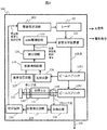
- FIG. 1 is a block diagram illustrating an overall configuration of a magnetic field measurement apparatus using an optical pumping magnetic sensor according to a first embodiment of the present invention. It is a block diagram which shows the light source part provided with the intensity
- FIG. 1 shows a schematic configuration of a magnetic field measuring apparatus according to an embodiment (Example 1) of the present invention.
- the magnetic field measurement apparatus includes a light source unit 100, a coil unit 107, a sensor unit 106, a magnetic shield unit 110, and a signal control processing unit 120.
- the light source unit 100 includes a laser 101, a drive power supply circuit 102, an intensity stabilization unit 103, and a frequency stabilization unit 104.
- the sensor excitation light 105 introduced into the sensor glass cell in which the alkali metal gas of the sensor unit 106 is sealed is introduced. appear.
- the light source is preferably a laser rather than a lamp. Therefore, the light source of the present embodiment uses a laser.
- the oscillation frequency of the laser includes an alkali metal absorption line (D 1 line, D 2 line), the laser spectral line width is equal to or smaller than the alkali metal absorption line width, and the laser oscillates in a single mode. Need to be. Therefore, considering not only the necessary laser operating conditions but also the practicality (cheap and small size), the laser to be used is a semiconductor laser.
- an external cavity semiconductor laser having an optical component such as a diffraction grating outside the laser element, or a distributed feedback laser (DFB laser) or a distributed reflection laser having a cavity length adjusting structure inside the laser element.
- DBR laser distributed feedback laser
- the laser 101 is driven by the drive power circuit 102 and oscillates. Temperature control is always performed at a set temperature using a Peltier element so that the laser element oscillates at a desired oscillation frequency.
- Temperature control is always performed at a set temperature using a Peltier element so that the laser element oscillates at a desired oscillation frequency.
- an external resonator type laser not only the temperature control of the laser element but also the setting of the injection current value to the laser element and the adjustment of the length of the external resonator composed of optical components such as a diffraction grating
- the mode hop where the oscillation frequency of the laser greatly deviates from the absorption line of the alkali metal is prevented.
- a DFB laser or a DBR laser in order to prevent mode hopping from occurring, not only temperature control of the laser element but also setting of an injection current value to the laser element is performed.
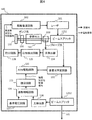
- FIG. 2 shows a detailed configuration of the light source unit 100 of the magnetic field measurement apparatus according to the first embodiment.
- Laser light output from the laser 101 enters an acousto-optic modulator (AOM) 121.
- AOM acousto-optic modulator
- the laser beam is emitted from the AOM, it is emitted as a laser beam separated into zero-order light, first-order light,..., N-order light (N is an integer) by Bragg diffraction.
- N is an integer
- the AOM 121 In order to adjust the incident laser light, if the AOM 121 has a position adjusting mechanism such as three axes (X axis, Y axis, Z axis) and angle ( ⁇ axis), the adjustment can be easily performed.
- the emitted laser light from the AOM 121 uses zero-order light, and the zero-order light is separated into two by a beam splitter 1251.
- One of the separated zero-order lights is detected by the photodetector 126 in order to stabilize the intensity of the laser light.
- the output voltage of the photodetector 126 and the output voltage of the reference voltage circuit 127 provided outside are input to the differential amplifier circuit 124.
- the output voltage of the differential amplifier circuit 124 is input to the AOM drive circuit 122 via the integration circuit 123.
- the AOM can also function as laser beam intensity adjustment, and when adjusting the intensity, the output voltage of the reference voltage circuit 127 is adjusted.
- Another one of the separated zero-order light is further separated into two laser beams by a beam splitter 1252.
- the separated laser light is used for stabilizing the frequency of the laser light and for excitation light of the sensor.
- an alkali metal absorption line or an interferometer described in the background art can be used as a reference for frequency stabilization.
- the frequency stability is the highest.
- frequency stabilization using an alkali metal absorption line is preferable in terms of simplicity and cost.
- the frequency stabilization of the present embodiment employs frequency stabilization using a practical absorption line of alkali metal atoms, and among them, saturated absorption spectroscopy, which is generally used, is used.
- the frequency stabilizing laser beam separated by the beam splitter 1252 is incident on the reference glass cell 131 containing only alkali metal in order to obtain an alkali metal absorption line.
- An ND file 133 and a mirror 132 are stacked on the side opposite to the laser beam incident side.
- the excitation of the alkali metal atoms is saturated with the pump light having a strong laser light intensity, and the absorption of the probe light is reduced at the resonance frequency of the alkali metal atoms that is saturated by sweeping the frequency of the probe light.
- the line width of the dent is the natural width of the alkali metal atom, and the frequency is stabilized by locking the laser frequency to the bottom or slope of the dent. Details of the control loop for stabilizing the frequency will be described in the case of using an external cavity semiconductor laser as the laser 101.
- the former structure is called a Littrow laser, and the latter structure is called a Littman laser.
- the laser frequency can be adjusted by adjusting the resonator length by the voltage applied to the piezoelectric element.
- the above-described resonator length is adjusted when the laser frequency is swept.
- the voltage signal of the piezoelectric element for modulation is modulated, and the distributed error signal obtained by detecting the modulated component by the phase detection circuit 129 is passed through the integration circuit 128, and the injected current of the piezoelectric element and the laser element is converted into the injected current.
- the slope of the slope is passed through the integration circuit as an error signal within a linearity range, and feedback is applied to the injection current of the piezoelectric element and the laser element.
- Another laser beam of the separated zero-order light is a laser beam that is frequency-stable and intensity-stable by the stabilization of the intensity and the stabilization of the frequency, and is introduced into the inside of the magnetic shield 110 to be detected by the sensor unit 106. Becomes the excitation light.
- the sensor unit 106 is placed inside the magnetic shield 110 together with the generation source of the magnetic field to be measured. Further, inside the magnetic shield 110, a static magnetic field coil 108 for applying a static magnetic field in the direction of 45 degrees to the optical axis of the excitation light to the glass cell of the sensor unit 106, and the static magnetic field An RF coil 109 that generates an oscillating magnetic field in an orthogonal direction is included.
- FIG. 3 shows the main structure of the sensor unit 106.
- the components shown in FIG. 3 are arranged as shown in a non-magnetic mold (not shown).
- the sensor excitation light guided from the light source unit by the optical fiber is introduced into the sensor glass cell 305 through the collimating lens 301 and the ⁇ / 4 wavelength plate 303.
- the excitation light becomes parallel light by the collimator lens 301, becomes circularly polarized light by the ⁇ / 4 wavelength plate 303, and enters the sensor glass cell 305.
- the laser light that has passed through the sensor glass cell 305 is condensed by the condenser lens 307 and guided to the photodiode 111 provided in the signal processing unit 120 of FIG.
- the sensor excitation light may be incident on the sensor glass cell as spatially propagated light. However, in consideration of practicality, it is preferably guided to the sensor glass cell by a polarization maintaining optical fiber.
- a polarizer or a ⁇ / 2 wavelength plate may be inserted between the collimating lens 301 and the ⁇ / 4 wavelength plate 303.
- the detection of the laser light that has passed through the sensor glass cell 305 may not only be detected directly by the photodetector, but also guided to the photodiode 111 via an optical fiber. In order to obtain high coupling efficiency, it is desirable to use a multimode optical fiber having a large core diameter. Multimode optical fibers generally do not have a polarization preserving function.
- the signal processing unit 120 further includes a current amplifier circuit 112, an amplifier filter circuit 113, a phase detection circuit 114, an AD conversion circuit 115, an oscillation circuit 116, a loop filter circuit 117, a stabilized power supply 118, and a PC 119.
- the current signal output from the photodiode 111 is converted into a voltage signal by the current amplifier circuit 112 and adjusted to a gain and a band necessary for measurement by the amplifier filter circuit 113.
- the phase detection circuit 114 detects the output of the amplifier filter circuit 113 using the signal from the oscillation circuit 116 as a reference signal.
- the detected phase signal is controlled not to oscillate by the loop filter circuit 117, and the output of the loop filter circuit 117 is input to the oscillation circuit 116, so that the oscillation frequency is voltage-controlled and thereby the RF magnetic field applied to the sensor unit 106.
- the feedback frequency is controlled.
- a weak magnetic field generated in a measurement object in the vicinity of the sensor glass cell 305 can be measured by a change in the output of the phase detection circuit 114 during feedback control.
- the photodiode 111 and the current amplifier circuit 112 are connected by a shield wire. However, it is more preferable that the two are integrated as a structure resistant to electromagnetic noise.
- the configuration of the light source unit is different from that of the first embodiment.
- the configuration of the magnetic measurement device is the same as that of the magnetic measurement device of the first embodiment shown in FIG.
- the structure of the light source part 140 of the magnetic measuring device of Example 2 is demonstrated along FIG.
- the same components as those of the light source unit of the first embodiment shown in FIG. 2 are denoted by the same reference numerals.
- the intensity stabilizing unit configured by the photodetector 126, the reference voltage circuit 127, the differential amplifier 124, the integrating circuit 123, the AOM driving circuit 122, and the acousto-optic modulator 121.
- the difference is that it is not inside the control loop for frequency stabilization that is fed back from the frequency stabilization section to the laser 101 via the drive power supply circuit 102, but in the subsequent stage of this control loop. That is, one of the split beams obtained by the first beam splitter 1251 that splits the laser beam output from the laser 101 that is the light source is introduced into the laminated structure of the half mirror 130, the reference cell 131, the ND filter 133, and the mirror 132. Is done.
- the extracted signal of the modulation component of the laser resonator length obtained by detecting the output of the photodetector 134 by the phase detection circuit 129 is integrated by the integration circuit 128 and fed back to the laser drive power supply circuit 102 to stabilize the frequency of the laser 101. Acts as a control signal.
- the other split light of the laser light whose frequency is stabilized by the control loop described above is guided from the beam splitter 1251 to the acousto-optic modulator 121.
- the acousto-optic modulator 121 is a control circuit that includes a photodetector 126 that detects split light obtained from the second beam splitter 1252, a reference voltage circuit 127, a differential amplifier 124, an integration circuit 123, and an AOM drive circuit 122.
- the intensity of the output light is controlled to be constant by controlling the obtained intensity stabilization control signal.
- the control loop is configured in the order of the frequency stabilizing unit and the intensity stabilizing unit, and the sensor excitation light 105 is obtained through these control loops.
- the configuration after the sensor glass cell into which the excitation light 105 is introduced is exactly the same as that of the first embodiment.
- both the light intensity fluctuation and the frequency fluctuation of the excitation laser light are eliminated, and a stable excitation light source is used. Highly accurate optical pumping magnetic measurement is possible.
- the excitation light introduced into the sensor glass cell is not a single-wavelength laser beam as in Example 1, but the absorption of alkali metal used in the sensor glass cell.
- a mixed light of each laser beam D 1 line and D 2 line is a line as the excitation light.
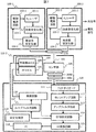
- FIG. 5 shows the overall configuration of the magnetic measurement apparatus according to the third embodiment.
- the light source units 100-1 and 100-2 are independent from each other.
- Light source unit 100-1 includes D 1 line laser 101-1 intensity stabilization unit 103-1, a frequency stabilizing unit 104-1, the driving power source circuit 102-1, and detailed configurations are shown in FIG. 2 embodiment This is the same as the light source unit 100 of Example 1.
- Light source unit 100-2 also in the same manner D 2-wire laser 101-2, intensity stabilization unit 103-2, the frequency stabilization section 104-2 includes a drive power source circuit 102-2, in FIG. 2 and the detailed structure There is no difference with the light source part 100 of Example 1 shown. Therefore, the structure until the laser beam intensity is stabilized and the frequency is stabilized in each light source unit is the same as that of the first embodiment shown in FIG.
- Each laser beam whose intensity is stabilized and whose frequency is stabilized is converted into parallel light by a collimator lens, and then converted into circularly polarized light through a ⁇ / 4 wavelength plate.
- Each laser beam that has become circularly polarized light is superimposed on the same axis using a half mirror 230 to become mixed light.
- This mixed light is incident on a sensor cell provided in the magnetic shield 110-1.
- the configuration inside the magnetic shield 110-1 is different from the magnetic shield of the first embodiment in that it has a diffraction grating 234 that allows the laser beam that has passed through the sensor glass cell to enter.
- the laser light passing through the glass cell using a diffraction grating 234 separates each of D 1 laser light and D 2 laser beam is detected as either signal for magnetic measurement by extracting only the laser beam.
- the configuration and operation of the signal processing unit 120 after the photodiode 111 that detects the extracted laser light is the same as in the first embodiment.
- the superimposed D 1 laser light and D 2 laser light are used as excitation light, so that one of the laser lights becomes pump-probe light for magnetic measurement, and the other laser light. Functions as a re-pumping light for improving the signal-to-noise ratio of the magnetic measurement signal.
- the magnetic measuring device of the third embodiment among the alkali metal atoms (for example, cesium atoms) in the sensor crow cell, atoms at the ground level F4 and atoms at the ground level F3 can also be excited. Therefore, there is an advantage that the magnetic detection sensitivity of the optical pumping magnetometer is further improved as compared with the apparatuses of the first and second embodiments.
- the pump-probe light can be either D 1 laser light or D 2 laser light. That is, the same can be said for the re-pumped light. However, it is more effective if the D 1 laser light is pump-probe light and the D 2 laser light is re-pump light. This is because towards D 1 line is wider spacing of the energy transition of the alkali metal atoms than two-wire D, which is why it can be less different impact energy transition close to the energy transition to be used.
- FIG. 6 shows the overall configuration of a magnetic measuring apparatus according to the fourth embodiment (Example 4) of the present invention.
- a mixed light of each laser beam D 1 line and D 2 line is an absorption line of the alkali metal used in the same manner as glass cell sensor of Example 3 as the excitation light.
- it comprises a light source unit 140-1 and 140-2 to generate D 1 laser light and D 2 laser beam, respectively.
- these light source units do not include an intensity stabilizing unit inside a control loop for frequency stabilization.
- the intensity stabilizing units 103-1 and 103-2 are respectively provided in the subsequent stage of the control loop created by the frequency stabilizing unit 104-1 and the subsequent stage of the control loop created by the frequency stabilizing unit 104-2.
- the detailed configuration of these light source sections 140-1 and 140-2 is the same as that shown in FIG. However, in FIG. 6, the inside of the light source units 140-1 and 140-2 is shown in a schematic block configuration.
- the D 1 laser beam from the light source unit 140-1 and the D 2 laser beam from the light source unit 140-2 are made into circularly polarized light parallel to each other by a collimator lens and a ⁇ / 4 wavelength plate, and are coaxially formed by the half mirror 140.
- the light beams are superimposed on each other and become mixed light. Further, through the laser light passing through the glass cell sensor of the sensor unit 106 to the diffraction grating 234, it has also configured to detect by extracting one of D 1 laser light and D 2 laser magnetic measurement of Example 3 It is exactly the same as the device.
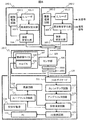
- FIG. 7 shows the overall configuration of the magnetic measuring apparatus according to the fifth embodiment (Embodiment 5) of the present invention.
- a mixed light of each laser beam D 1 line and D 2 line is an absorption line of the alkali metal used in the same manner as glass cell sensor of Example 3 as the excitation light.
- it comprises a light source unit 140-1 and 140-2 to generate D 1 laser light and D 2 laser beam, respectively.
- the structure until the laser beam is stabilized in intensity and frequency and the device configuration for guiding the excitation light to the sensor unit are the same as those in the third embodiment shown in FIG.
- Each laser beam whose intensity is stabilized and whose frequency is stabilized is converted into parallel light by a collimator lens, and then converted into circularly polarized light through a ⁇ / 4 wavelength plate.
- Each laser beam that has become circularly polarized light is superimposed on the same axis using a half mirror 230 to become mixed light.
- This mixed light is incident on a sensor cell provided in the magnetic shield 110-2.
- the magnetic shield of the third embodiment is that a ⁇ / 4 wavelength plate 2000 and a polarization beam splitter 2001 are used instead of the diffraction grating 234 for entering the laser beam that has passed through the sensor glass cell. And different.
- the ⁇ / 4 wavelength plate 2000 converts the D 1 laser light and D 2 laser light that have passed through the glass cell from circularly polarized light to linearly polarized light.
- D 1 laser light and D 2 laser beam is polarization beam splitter 2001, to separate each of the D 1 laser light and D 2 laser beam, extracted magnetically measured only one of the laser beam It is detected as a signal for use.
- the configuration and operation of the signal processing unit 120 after the photodiode 111 that detects the extracted laser light are the same as those in the third embodiment.
- FIG. 8 shows the entire configuration of the magnetic measuring apparatus according to the sixth embodiment (sixth embodiment) of the present invention.
- a mixed light of each laser beam D 1 line and D 2 line is an absorption line of the alkali metal used in the same manner as glass cell sensor of Example 3 as the excitation light.
- it comprises a light source unit 140-1 and 140-2 to generate D 1 laser light and D 2 laser beam, respectively.
- the structure until the laser beam is stabilized in intensity and frequency and the device configuration for guiding the excitation light to the sensor unit are the same as those in the third embodiment shown in FIG.
- the intensity stabilizing units 103-1 and 103-2 are respectively provided in the subsequent stage of the control loop created by the frequency stabilizing unit 104-1 and the subsequent stage of the control loop created by the frequency stabilizing unit 104-2.
- the detailed configuration of these light source sections 140-1 and 140-2 is the same as that shown in FIG.
- the configuration inside the magnetic shield 110-2 is exactly the same as that of the fifth embodiment.
- the D 1 laser beam from the light source unit 140-1 and the D 2 laser beam from the light source unit 140-2 are made into circularly polarized light parallel to each other by a collimator lens and a ⁇ / 4 wavelength plate, and are coaxially formed by the half mirror 140.
- the light beams are superimposed on each other and become mixed light. Further, the laser light passing through the sensor glass cell of the sensor unit 106 and the lambda / 4 wave plate 2000, through the polarization beam splitter 2001, has been detected by extracting one of D 1 laser light and D 2 laser beam
- the configuration to be performed is exactly the same as that of the magnetic measurement apparatus of the fifth embodiment.
Abstract
Priority Applications (3)
| Application Number | Priority Date | Filing Date | Title |
|---|---|---|---|
| JP2015529297A JPWO2015015628A1 (ja) | 2013-08-02 | 2013-08-02 | 磁場計測装置 |
| US14/905,132 US10162021B2 (en) | 2013-08-02 | 2013-08-02 | Magnetic field measurement device |
| PCT/JP2013/070958 WO2015015628A1 (fr) | 2013-08-02 | 2013-08-02 | Dispositif de mesure de champ magnétique |
Applications Claiming Priority (1)
| Application Number | Priority Date | Filing Date | Title |
|---|---|---|---|
| PCT/JP2013/070958 WO2015015628A1 (fr) | 2013-08-02 | 2013-08-02 | Dispositif de mesure de champ magnétique |
Publications (1)
| Publication Number | Publication Date |
|---|---|
| WO2015015628A1 true WO2015015628A1 (fr) | 2015-02-05 |
Family
ID=52431200
Family Applications (1)
| Application Number | Title | Priority Date | Filing Date |
|---|---|---|---|
| PCT/JP2013/070958 WO2015015628A1 (fr) | 2013-08-02 | 2013-08-02 | Dispositif de mesure de champ magnétique |
Country Status (3)
| Country | Link |
|---|---|
| US (1) | US10162021B2 (fr) |
| JP (1) | JPWO2015015628A1 (fr) |
| WO (1) | WO2015015628A1 (fr) |
Cited By (4)
| Publication number | Priority date | Publication date | Assignee | Title |
|---|---|---|---|---|
| US20160146909A1 (en) * | 2013-08-02 | 2016-05-26 | Hitachi, Ltd. | Magnetic field measurement device |
| CN109765507A (zh) * | 2018-12-29 | 2019-05-17 | 中国船舶重工集团公司第七一0研究所 | 一种基于双吸收室的自激式激光光泵磁力仪系统 |
| WO2023162328A1 (fr) * | 2022-02-25 | 2023-08-31 | 浜松ホトニクス株式会社 | Module de capteur magnétique et procédé de détermination d'état de fonctionnement d'un module de capteur magnétique |
| JP7365268B2 (ja) | 2020-03-04 | 2023-10-19 | 浜松ホトニクス株式会社 | 光励起磁気センサ及び光励起磁気測定方法 |
Families Citing this family (13)
| Publication number | Priority date | Publication date | Assignee | Title |
|---|---|---|---|---|
| US10274549B1 (en) * | 2016-07-13 | 2019-04-30 | AOSense, Inc. | Scalar atomic magnetometer with heading error suppression |
| US10514413B2 (en) | 2016-09-26 | 2019-12-24 | KW Associates LLC | Estimation of arc location in three dimensions |
| US10042192B2 (en) * | 2016-11-28 | 2018-08-07 | Futurewei Technologies, Inc. | Electro-absorption modulator with local temperature control |
| US10782368B2 (en) | 2017-05-31 | 2020-09-22 | Northrop Grumman Systems Corporation | Pulsed-beam atomic magnetometer system |
| US10823790B2 (en) * | 2017-05-31 | 2020-11-03 | Northrop Grumman Systems Corporation | Pulsed-beam atomic magnetometer system |
| US20190018085A1 (en) * | 2017-07-11 | 2019-01-17 | Lockheed Martin Corporation | Magnetometer with thermal electric cooling of the excitation light source |
| US10809342B2 (en) | 2017-10-02 | 2020-10-20 | Northrop Grumman Systems Corporation | Calibration of a magnetometer system |
| CN108227010B (zh) * | 2017-12-29 | 2019-03-05 | 清华大学 | 面向埋地未爆弹的专用铯光泵探测器 |
| US10761116B2 (en) | 2018-01-12 | 2020-09-01 | KW Associates LLC | Sensing and control of position of an electrical discharge |
| CN111244754B (zh) * | 2020-01-22 | 2021-06-22 | 杭州电子科技大学 | 一种基于亚自然线宽光谱的激光稳频装置及方法 |
| US11243273B2 (en) | 2020-03-16 | 2022-02-08 | KW Associates LLC | Estimation or control of lengths and positions of one or more transversely localized electric current segments flowing between two conductive bodies |
| US11294005B2 (en) | 2020-07-14 | 2022-04-05 | Northrop Grumman Systems Corporation | Synchronous light-pulse atomic magnetometer system |
| CN115932676B (zh) * | 2023-01-31 | 2023-11-03 | 柏瑞润兴(北京)科技发展有限公司 | 一种磁场检测装置 |
Citations (2)
| Publication number | Priority date | Publication date | Assignee | Title |
|---|---|---|---|---|
| JPH0550758U (ja) * | 1991-12-04 | 1993-07-02 | 横河電機株式会社 | 周波数安定化レーザ光源 |
| JP2009128235A (ja) * | 2007-11-26 | 2009-06-11 | Hitachi High-Technologies Corp | 光ポンピング磁力計 |
Family Cites Families (48)
| Publication number | Priority date | Publication date | Assignee | Title |
|---|---|---|---|---|
| FR1594565A (fr) * | 1968-07-08 | 1970-06-08 | ||
| FR2070978A5 (fr) * | 1969-12-12 | 1971-09-17 | Anvar | |
| DE2015612A1 (de) * | 1970-04-01 | 1971-10-21 | Siemens Ag | Frequenzstabilisierte Laseranordnung |
| US3596201A (en) * | 1970-06-08 | 1971-07-27 | Hughes Aircraft Co | Frequency stabilized laser |
| US3829838A (en) * | 1970-11-05 | 1974-08-13 | Battelle Development Corp | Computer-controlled three-dimensional pattern generator |
| FR2180573B1 (fr) * | 1972-04-21 | 1977-01-14 | Anvar | |
| FR2270698B1 (fr) * | 1974-05-10 | 1980-03-28 | Anvar | |
| JPS5919875A (ja) * | 1982-07-27 | 1984-02-01 | Toshiba Corp | 磁界測定装置 |
| US4779279A (en) * | 1984-03-05 | 1988-10-18 | Beckman Instruments, Inc. | Magnetic laser control |
| JPS62188291A (ja) * | 1986-02-13 | 1987-08-17 | Yokogawa Electric Corp | 半導体レ−ザ波長安定化装置 |
| JPH0263321A (ja) * | 1988-08-30 | 1990-03-02 | Yokogawa Electric Corp | 周波数標準器 |
| US5036278A (en) * | 1989-09-29 | 1991-07-30 | Polatomic, Inc. | Radiation source for helium magnetometers |
| JP2962568B2 (ja) * | 1990-09-27 | 1999-10-12 | アンリツ株式会社 | 周波数安定化レーザ光源 |
| US5706079A (en) * | 1995-09-29 | 1998-01-06 | The United States Of America As Represented By The Secretary Of The Navy | Ultra-high sensitivity transducer with chirped bragg grating relector |
| US20020018404A1 (en) * | 1996-07-12 | 2002-02-14 | Hitachi Maxell, Ltd. | Magneto-optical recording medium having different magnetic domain radii in recording layer and reproduction layer |
| JP4080538B2 (ja) * | 1996-08-27 | 2008-04-23 | 日立マクセル株式会社 | 光磁気記録媒体の再生方法及び再生装置 |
| FR2799014B1 (fr) * | 1999-09-27 | 2001-12-07 | Univ Paris 13 | Procede et installation de nanolithographie par interferometrie atomique |
| JP2002314187A (ja) | 2001-04-12 | 2002-10-25 | Mitsubishi Electric Corp | レーザダイオードモジュール及び光送信機 |
| US6472869B1 (en) * | 2001-06-18 | 2002-10-29 | United States Of America As Represented By The Secretary Of The Air Force | Diode laser-pumped magnetometer |
| US6831522B2 (en) * | 2001-07-09 | 2004-12-14 | The United States Of America As Represented By The Secretary Of Commerce | Method of minimizing the short-term frequency instability of laser-pumped atomic clocks |
| US7038450B2 (en) * | 2002-10-16 | 2006-05-02 | Trustees Of Princeton University | High sensitivity atomic magnetometer and methods for using same |
| US6888780B2 (en) * | 2003-04-11 | 2005-05-03 | Princeton University | Method and system for operating an atomic clock with simultaneous locking of field and frequency |
| JP3811778B2 (ja) | 2003-08-20 | 2006-08-23 | 独立行政法人情報通信研究機構 | レーザー周波数安定化装置、及びレーザー周波数安定化方法 |
| EP1725901A1 (fr) * | 2004-03-16 | 2006-11-29 | Sign-Tronic AG | Procede de formation d'un faisceau lumineux d'une intensite lumineuse sensiblement constante |
| JP5005256B2 (ja) * | 2005-11-28 | 2012-08-22 | 株式会社日立ハイテクノロジーズ | 磁場計測システム及び光ポンピング磁束計 |
| US7468637B2 (en) * | 2006-04-19 | 2008-12-23 | Sarnoff Corporation | Batch-fabricated, RF-interrogated, end transition, chip-scale atomic clock |
| JP2008153320A (ja) | 2006-12-15 | 2008-07-03 | Hitachi Ltd | 光源システム |
| JP5039452B2 (ja) * | 2007-06-27 | 2012-10-03 | 株式会社日立ハイテクノロジーズ | 磁場計測装置 |
| JP2009080310A (ja) * | 2007-09-26 | 2009-04-16 | Toshiba Corp | 量子計算機および量子計算方法 |
| US8264693B2 (en) * | 2007-12-06 | 2012-09-11 | The Regents Of The University Of Michigan | Method and system for measuring at least one property including a magnetic property of a material using pulsed laser sources |
| JP5178187B2 (ja) * | 2007-12-28 | 2013-04-10 | キヤノン株式会社 | 原子磁気センサ、及び磁気センシング方法 |
| US7902927B2 (en) * | 2008-06-18 | 2011-03-08 | Sri International | System and method for modulating pressure in an alkali-vapor cell |
| JP5640335B2 (ja) * | 2009-06-26 | 2014-12-17 | セイコーエプソン株式会社 | 磁気センサー |
| JP2011089868A (ja) * | 2009-10-22 | 2011-05-06 | Seiko Epson Corp | ファイバーセル、磁気センサー、及び磁界測定装置 |
| JP5446731B2 (ja) * | 2009-10-29 | 2014-03-19 | セイコーエプソン株式会社 | 磁場測定装置 |
| US8581580B2 (en) * | 2010-06-02 | 2013-11-12 | Halliburton Energy Services, Inc. | Downhole orientation sensing with nuclear spin gyroscope |
| JP6134092B2 (ja) * | 2011-10-18 | 2017-05-24 | セイコーエプソン株式会社 | 磁場計測装置 |
| US9310447B2 (en) * | 2011-11-18 | 2016-04-12 | Hitachi, Ltd. | Magnetic field measuring apparatus and method for manufacturing same |
| US9366735B2 (en) * | 2012-04-06 | 2016-06-14 | Hitachi, Ltd. | Optical pumping magnetometer |
| US9810756B2 (en) * | 2012-10-11 | 2017-11-07 | The Penn State Research Foundation | Zero- and low-field transport detection system |
| US9229073B2 (en) * | 2012-12-27 | 2016-01-05 | Northrop Grumman Guidance And Electronics Company, Inc. | Systems and method to substantially mitigate AC stark shift effects in a sensor system |
| JP6171355B2 (ja) * | 2013-01-21 | 2017-08-02 | セイコーエプソン株式会社 | 磁場計測装置 |
| WO2015015628A1 (fr) * | 2013-08-02 | 2015-02-05 | 株式会社日立製作所 | Dispositif de mesure de champ magnétique |
| WO2015083242A1 (fr) * | 2013-12-03 | 2015-06-11 | 株式会社日立製作所 | Appareil de source de lumière et appareil de mesure de champ magnétique |
| US9869731B1 (en) * | 2014-03-31 | 2018-01-16 | The Regents Of The University Of California | Wavelength-modulated coherence pumping and hyperfine repumping for an atomic magnetometer |
| US9829544B2 (en) * | 2014-05-05 | 2017-11-28 | Northrop Grumman Systems Corporation | Magnetic field trimming in an atomic sensor system |
| US9726494B2 (en) * | 2014-05-15 | 2017-08-08 | Northrop Grumman Systems Corporation | Atomic sensor system |
| JP2017026405A (ja) * | 2015-07-21 | 2017-02-02 | キヤノン株式会社 | 光ポンピング磁力計および磁気センシング方法 |
-
2013
- 2013-08-02 WO PCT/JP2013/070958 patent/WO2015015628A1/fr active Application Filing
- 2013-08-02 US US14/905,132 patent/US10162021B2/en active Active
- 2013-08-02 JP JP2015529297A patent/JPWO2015015628A1/ja active Pending
Patent Citations (2)
| Publication number | Priority date | Publication date | Assignee | Title |
|---|---|---|---|---|
| JPH0550758U (ja) * | 1991-12-04 | 1993-07-02 | 横河電機株式会社 | 周波数安定化レーザ光源 |
| JP2009128235A (ja) * | 2007-11-26 | 2009-06-11 | Hitachi High-Technologies Corp | 光ポンピング磁力計 |
Cited By (5)
| Publication number | Priority date | Publication date | Assignee | Title |
|---|---|---|---|---|
| US20160146909A1 (en) * | 2013-08-02 | 2016-05-26 | Hitachi, Ltd. | Magnetic field measurement device |
| US10162021B2 (en) * | 2013-08-02 | 2018-12-25 | Hitachi, Ltd. | Magnetic field measurement device |
| CN109765507A (zh) * | 2018-12-29 | 2019-05-17 | 中国船舶重工集团公司第七一0研究所 | 一种基于双吸收室的自激式激光光泵磁力仪系统 |
| JP7365268B2 (ja) | 2020-03-04 | 2023-10-19 | 浜松ホトニクス株式会社 | 光励起磁気センサ及び光励起磁気測定方法 |
| WO2023162328A1 (fr) * | 2022-02-25 | 2023-08-31 | 浜松ホトニクス株式会社 | Module de capteur magnétique et procédé de détermination d'état de fonctionnement d'un module de capteur magnétique |
Also Published As
| Publication number | Publication date |
|---|---|
| JPWO2015015628A1 (ja) | 2017-03-02 |
| US20160146909A1 (en) | 2016-05-26 |
| US10162021B2 (en) | 2018-12-25 |
Similar Documents
| Publication | Publication Date | Title |
|---|---|---|
| WO2015015628A1 (fr) | Dispositif de mesure de champ magnétique | |
| US10215816B2 (en) | Magnetic field measuring apparatus | |
| JP6063927B2 (ja) | 磁場計測装置 | |
| US7379486B2 (en) | Technique for optically pumping alkali-metal atoms using CPT resonances | |
| US8237514B2 (en) | Quantum interference device, atomic oscillator, and magnetic sensor | |
| JP5954457B2 (ja) | 量子干渉装置 | |
| US20190341739A1 (en) | Narrow-linewidth microcavity brillouin laser with suppressed temperature fluctuations | |
| CA2792032A1 (fr) | Procede et appareil pour l'identification et la quantification photoacoustiques d'especes d'analytes dans un milieu gazeux ou liquide | |
| US10790634B2 (en) | Laser system with optical feedback | |
| CA2491700A1 (fr) | Laser a semiconducteurs stabilise offrant une haute coherence de frequence | |
| Terra et al. | An ultra-stable optical frequency standard for telecommunication purposes based upon the 5S 1/2→ 5D 5/2 two-photon transition in Rubidium | |
| CN114899702A (zh) | 一种基于光纤环形谐振腔的激光器偏频稳频装置及方法 | |
| WO2021124790A1 (fr) | Dispositif de source de lumière pour gyroscope à fibre optique et gyroscope à fibre optique l'utilisant | |
| JP2009141048A (ja) | 光学系及び原子発振器 | |
| CN110911963B (zh) | 一种高稳定性的偏振光谱稳频装置 | |
| CN105762640B (zh) | 一种用于亚多普勒饱和吸收光谱的反射式集成装置 | |
| Beverini et al. | Frequency stabilization of a diode laser on the Cs D2 resonance line by the Zeeman effect in a vapor cell | |
| US9735541B1 (en) | Calibration of external-cavity tunable lasers | |
| JP3969666B2 (ja) | 波長可変レーザー装置 | |
| JP2011249400A (ja) | レーザ光源の調整システム、及びレーザ光源の調整方法 | |
| KR100559185B1 (ko) | 전자기 유도 투과성을 이용하는 레이저 주파수 안정화방법 및 장치 | |
| JP2011249399A (ja) | レーザ光源、及びレーザ光源の調整システム | |
| JP4547513B2 (ja) | 多重飽和分光によるレーザー周波数安定化装置 | |
| Gawlik et al. | Stabilization of diode-laser frequency to atomic transitions | |
| Watkins et al. | High power VCSEL devices for atomic clock applications |
Legal Events
| Date | Code | Title | Description |
|---|---|---|---|
| 121 | Ep: the epo has been informed by wipo that ep was designated in this application |
Ref document number: 13890587 Country of ref document: EP Kind code of ref document: A1 |
|
| ENP | Entry into the national phase |
Ref document number: 2015529297 Country of ref document: JP Kind code of ref document: A |
|
| WWE | Wipo information: entry into national phase |
Ref document number: 14905132 Country of ref document: US |
|
| NENP | Non-entry into the national phase |
Ref country code: DE |
|
| 122 | Ep: pct application non-entry in european phase |
Ref document number: 13890587 Country of ref document: EP Kind code of ref document: A1 |