WO2021124790A1 - Dispositif de source de lumière pour gyroscope à fibre optique et gyroscope à fibre optique l'utilisant - Google Patents
Dispositif de source de lumière pour gyroscope à fibre optique et gyroscope à fibre optique l'utilisant Download PDFInfo
- Publication number
- WO2021124790A1 WO2021124790A1 PCT/JP2020/043273 JP2020043273W WO2021124790A1 WO 2021124790 A1 WO2021124790 A1 WO 2021124790A1 JP 2020043273 W JP2020043273 W JP 2020043273W WO 2021124790 A1 WO2021124790 A1 WO 2021124790A1
- Authority
- WO
- WIPO (PCT)
- Prior art keywords
- light
- optical fiber
- light source
- optical
- fiber gyroscope
- Prior art date
Links
- 239000013307 optical fiber Substances 0.000 title claims abstract description 233
- 238000001228 spectrum Methods 0.000 claims abstract description 103
- 230000000087 stabilizing effect Effects 0.000 claims abstract description 36
- 230000003287 optical effect Effects 0.000 claims description 117
- 238000006243 chemical reaction Methods 0.000 claims description 20
- 230000001360 synchronised effect Effects 0.000 claims description 17
- 230000006641 stabilisation Effects 0.000 claims description 10
- 238000011105 stabilization Methods 0.000 claims description 10
- 238000001514 detection method Methods 0.000 claims description 9
- 230000006798 recombination Effects 0.000 claims description 9
- 238000005215 recombination Methods 0.000 claims description 9
- 230000005284 excitation Effects 0.000 claims description 7
- 239000000835 fiber Substances 0.000 claims description 7
- 230000002452 interceptive effect Effects 0.000 claims description 7
- 239000003381 stabilizer Substances 0.000 claims 2
- 238000010586 diagram Methods 0.000 description 16
- 238000004847 absorption spectroscopy Methods 0.000 description 8
- 239000004065 semiconductor Substances 0.000 description 8
- 239000007789 gas Substances 0.000 description 6
- 230000010287 polarization Effects 0.000 description 6
- 230000008878 coupling Effects 0.000 description 4
- 238000010168 coupling process Methods 0.000 description 4
- 238000005859 coupling reaction Methods 0.000 description 4
- 230000006866 deterioration Effects 0.000 description 3
- 230000000694 effects Effects 0.000 description 3
- 238000010521 absorption reaction Methods 0.000 description 2
- 230000008901 benefit Effects 0.000 description 2
- 238000007796 conventional method Methods 0.000 description 2
- 239000013078 crystal Substances 0.000 description 2
- 239000011521 glass Substances 0.000 description 2
- 230000033001 locomotion Effects 0.000 description 2
- 230000007774 longterm Effects 0.000 description 2
- 239000010453 quartz Substances 0.000 description 2
- 229910052701 rubidium Inorganic materials 0.000 description 2
- 229920006395 saturated elastomer Polymers 0.000 description 2
- VYPSYNLAJGMNEJ-UHFFFAOYSA-N silicon dioxide Inorganic materials O=[Si]=O VYPSYNLAJGMNEJ-UHFFFAOYSA-N 0.000 description 2
- 238000000559 atomic spectroscopy Methods 0.000 description 1
- 230000008859 change Effects 0.000 description 1
- 230000003111 delayed effect Effects 0.000 description 1
- 238000005516 engineering process Methods 0.000 description 1
- 238000012986 modification Methods 0.000 description 1
- 230000004048 modification Effects 0.000 description 1
- IGLNJRXAVVLDKE-UHFFFAOYSA-N rubidium atom Chemical compound [Rb] IGLNJRXAVVLDKE-UHFFFAOYSA-N 0.000 description 1
- 230000035945 sensitivity Effects 0.000 description 1
- 230000003595 spectral effect Effects 0.000 description 1
- 230000007480 spreading Effects 0.000 description 1
Images


Classifications
-
- H—ELECTRICITY
- H01—ELECTRIC ELEMENTS
- H01S—DEVICES USING THE PROCESS OF LIGHT AMPLIFICATION BY STIMULATED EMISSION OF RADIATION [LASER] TO AMPLIFY OR GENERATE LIGHT; DEVICES USING STIMULATED EMISSION OF ELECTROMAGNETIC RADIATION IN WAVE RANGES OTHER THAN OPTICAL
- H01S3/00—Lasers, i.e. devices using stimulated emission of electromagnetic radiation in the infrared, visible or ultraviolet wave range
- H01S3/10—Controlling the intensity, frequency, phase, polarisation or direction of the emitted radiation, e.g. switching, gating, modulating or demodulating
- H01S3/13—Stabilisation of laser output parameters, e.g. frequency or amplitude
- H01S3/1303—Stabilisation of laser output parameters, e.g. frequency or amplitude by using a passive reference, e.g. absorption cell
-
- G—PHYSICS
- G02—OPTICS
- G02F—OPTICAL DEVICES OR ARRANGEMENTS FOR THE CONTROL OF LIGHT BY MODIFICATION OF THE OPTICAL PROPERTIES OF THE MEDIA OF THE ELEMENTS INVOLVED THEREIN; NON-LINEAR OPTICS; FREQUENCY-CHANGING OF LIGHT; OPTICAL LOGIC ELEMENTS; OPTICAL ANALOGUE/DIGITAL CONVERTERS
- G02F1/00—Devices or arrangements for the control of the intensity, colour, phase, polarisation or direction of light arriving from an independent light source, e.g. switching, gating or modulating; Non-linear optics
- G02F1/35—Non-linear optics
- G02F1/39—Non-linear optics for parametric generation or amplification of light, infrared or ultraviolet waves
-
- G—PHYSICS
- G01—MEASURING; TESTING
- G01C—MEASURING DISTANCES, LEVELS OR BEARINGS; SURVEYING; NAVIGATION; GYROSCOPIC INSTRUMENTS; PHOTOGRAMMETRY OR VIDEOGRAMMETRY
- G01C19/00—Gyroscopes; Turn-sensitive devices using vibrating masses; Turn-sensitive devices without moving masses; Measuring angular rate using gyroscopic effects
- G01C19/58—Turn-sensitive devices without moving masses
- G01C19/64—Gyrometers using the Sagnac effect, i.e. rotation-induced shifts between counter-rotating electromagnetic beams
- G01C19/72—Gyrometers using the Sagnac effect, i.e. rotation-induced shifts between counter-rotating electromagnetic beams with counter-rotating light beams in a passive ring, e.g. fibre laser gyrometers
- G01C19/721—Details
-
- G—PHYSICS
- G02—OPTICS
- G02F—OPTICAL DEVICES OR ARRANGEMENTS FOR THE CONTROL OF LIGHT BY MODIFICATION OF THE OPTICAL PROPERTIES OF THE MEDIA OF THE ELEMENTS INVOLVED THEREIN; NON-LINEAR OPTICS; FREQUENCY-CHANGING OF LIGHT; OPTICAL LOGIC ELEMENTS; OPTICAL ANALOGUE/DIGITAL CONVERTERS
- G02F1/00—Devices or arrangements for the control of the intensity, colour, phase, polarisation or direction of light arriving from an independent light source, e.g. switching, gating or modulating; Non-linear optics
- G02F1/35—Non-linear optics
- G02F1/37—Non-linear optics for second-harmonic generation
-
- G—PHYSICS
- G02—OPTICS
- G02F—OPTICAL DEVICES OR ARRANGEMENTS FOR THE CONTROL OF LIGHT BY MODIFICATION OF THE OPTICAL PROPERTIES OF THE MEDIA OF THE ELEMENTS INVOLVED THEREIN; NON-LINEAR OPTICS; FREQUENCY-CHANGING OF LIGHT; OPTICAL LOGIC ELEMENTS; OPTICAL ANALOGUE/DIGITAL CONVERTERS
- G02F2203/00—Function characteristic
- G02F2203/56—Frequency comb synthesizer
-
- H—ELECTRICITY
- H01—ELECTRIC ELEMENTS
- H01S—DEVICES USING THE PROCESS OF LIGHT AMPLIFICATION BY STIMULATED EMISSION OF RADIATION [LASER] TO AMPLIFY OR GENERATE LIGHT; DEVICES USING STIMULATED EMISSION OF ELECTROMAGNETIC RADIATION IN WAVE RANGES OTHER THAN OPTICAL
- H01S5/00—Semiconductor lasers
- H01S5/005—Optical components external to the laser cavity, specially adapted therefor, e.g. for homogenisation or merging of the beams or for manipulating laser pulses, e.g. pulse shaping
- H01S5/0078—Optical components external to the laser cavity, specially adapted therefor, e.g. for homogenisation or merging of the beams or for manipulating laser pulses, e.g. pulse shaping for frequency filtering
-
- H—ELECTRICITY
- H01—ELECTRIC ELEMENTS
- H01S—DEVICES USING THE PROCESS OF LIGHT AMPLIFICATION BY STIMULATED EMISSION OF RADIATION [LASER] TO AMPLIFY OR GENERATE LIGHT; DEVICES USING STIMULATED EMISSION OF ELECTROMAGNETIC RADIATION IN WAVE RANGES OTHER THAN OPTICAL
- H01S5/00—Semiconductor lasers
- H01S5/005—Optical components external to the laser cavity, specially adapted therefor, e.g. for homogenisation or merging of the beams or for manipulating laser pulses, e.g. pulse shaping
- H01S5/0085—Optical components external to the laser cavity, specially adapted therefor, e.g. for homogenisation or merging of the beams or for manipulating laser pulses, e.g. pulse shaping for modulating the output, i.e. the laser beam is modulated outside the laser cavity
-
- H—ELECTRICITY
- H01—ELECTRIC ELEMENTS
- H01S—DEVICES USING THE PROCESS OF LIGHT AMPLIFICATION BY STIMULATED EMISSION OF RADIATION [LASER] TO AMPLIFY OR GENERATE LIGHT; DEVICES USING STIMULATED EMISSION OF ELECTROMAGNETIC RADIATION IN WAVE RANGES OTHER THAN OPTICAL
- H01S5/00—Semiconductor lasers
- H01S5/005—Optical components external to the laser cavity, specially adapted therefor, e.g. for homogenisation or merging of the beams or for manipulating laser pulses, e.g. pulse shaping
- H01S5/0092—Optical components external to the laser cavity, specially adapted therefor, e.g. for homogenisation or merging of the beams or for manipulating laser pulses, e.g. pulse shaping for nonlinear frequency conversion, e.g. second harmonic generation [SHG] or sum- or difference-frequency generation outside the laser cavity
-
- H—ELECTRICITY
- H01—ELECTRIC ELEMENTS
- H01S—DEVICES USING THE PROCESS OF LIGHT AMPLIFICATION BY STIMULATED EMISSION OF RADIATION [LASER] TO AMPLIFY OR GENERATE LIGHT; DEVICES USING STIMULATED EMISSION OF ELECTROMAGNETIC RADIATION IN WAVE RANGES OTHER THAN OPTICAL
- H01S5/00—Semiconductor lasers
- H01S5/06—Arrangements for controlling the laser output parameters, e.g. by operating on the active medium
- H01S5/068—Stabilisation of laser output parameters
- H01S5/0683—Stabilisation of laser output parameters by monitoring the optical output parameters
- H01S5/0687—Stabilising the frequency of the laser
Definitions
- the present invention relates to a light source device for an optical fiber gyroscope and an optical fiber gyroscope using the same, and particularly to a light source device for an optical fiber gyroscope having improved stability of a scale factor and an optical fiber gyroscope using the same.
- GNSS Global Navigation Satellite System: Global Positioning Satellite System
- INS Inertial Navigation System: Inertial Navigation
- an optical fiber gyroscope (FOG: Fiber optic gyroscope) is known (for example, Patent Document 1).
- the FOG is a rotational angular velocity sensor that utilizes the Sagnac effect of light.
- the optical fiber gyroscope uses an optical fiber coil, has no moving part, is smaller than a conventional mechanical gyro, and is maintenance-free, and is attracting attention.
- the phase difference ⁇ generated according to the rotation angular velocity of the optical fiber gyroscope is obtained by multiplying the angular velocity ⁇ by the scale factor (SF) as a coefficient. That is, the coefficient of the angular velocity ⁇ on the right side of the mathematical formula of the phase difference ⁇ represented below is called a scale factor.
- R is the radius of the optical fiber coil
- N is the number of turns of the optical fiber coil
- ⁇ is the wavelength
- c is the speed of light.
- the scale factor corresponds to the ratio of the angular velocity to the output signal, and as can be seen from Equation 1, it is subject to fluctuations in the wavelength ⁇ . If the scale factor is not stable in time, the phase difference will fluctuate even at a constant angular velocity, and the sensor output will also fluctuate. As a result, no matter how high the sensitivity (output signal) is, the Alan deviation, which is an index of the accuracy of the gyroscope, becomes worse as it becomes longer. Therefore, it is necessary to increase the stability of the scale factor in order to improve the Alan deviation.
- Patent Document 2 As a stabilizing light source for driving an optical fiber gyroscope, for example, Patent Document 2 is provided. This is an attempt to eliminate the instability of the scale factor due to the asymmetry of the spectrum between the orthogonal axes of the wavelength. Patent Document 2 relates to a symmetric wavelength multiplexer, and reduces scale factor error by reducing spectral asymmetry between orthogonal axes of wavelength.
- a ring laser gyroscope is also known as a sensor similar to an optical fiber gyroscope (for example, Patent Document 3).
- the optical fiber gyroscope as in Patent Document 1 has a low scale factor stability.
- the stabilized light source as in Patent Document 2 has a good scale factor
- the band of the laser light is narrow, and the backscattering or polarization of light in the optical fiber coil is achieved. Performance deterioration due to wave coupling was unavoidable.
- a wide band laser beam is used, but when trying to widen the band, the center frequency (center wavelength) is not stable, and as a result.
- the scale factor was unstable.
- the ring laser gyroscope as in Patent Document 3 has a certain degree of good Alan deviation and high accuracy, but the apparatus itself is large and expensive. There was also a demand for a more accurate gyroscope.
- the present invention intends to provide a light source device for an optical fiber gyroscope capable of widening a wide band of laser light and improving the stability of a scale factor, and an optical fiber gyroscope using the same. It is a thing.
- the optical fiber gyroscope light source device stabilizes a laser light source that emits a laser beam of a predetermined frequency and a predetermined frequency of the laser beam emitted from the laser light source. It is provided with a stabilizing unit and a widening unit that converts the laser light stabilized by the stabilizing unit into light having a continuous wide band spectrum.
- the stabilizing unit may be any one that locks the laser beam emitted from the laser light source to the reference frequency source and stabilizes it.
- the laser light source may be any one composed of a continuous light laser light source that emits continuous light.
- the laser light source may be composed of a pulsed laser light source that emits light having a pulsed spectrum arranged at regular intervals at regular intervals.
- the broadband section receives the laser beam stabilized by the stabilizing section, and performs frequency modulation by white noise with a modulation width equal to or larger than a predetermined interval of the pulsed spectrum so as to form a continuous spectrum. Anything may be composed of a noise modulator.
- the broadband section includes an optical comb generation section in which laser light stabilized by the stabilizing section is input and emits light composed of a plurality of spectra arranged at regular intervals around a predetermined frequency. It is composed of a white noise modulator that receives light emitted from an optical comb generator and performs frequency modulation by white noise with a modulation width of a plurality of spectra at a predetermined interval or more so as to form a continuous spectrum. Is also good.
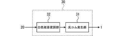
- the wideband section includes a white noise modulation section in which laser light stabilized by the stabilization section is input and frequency modulation by white noise is performed with a predetermined modulation width so as to have a continuous spectrum, and a white noise modulation section. It consists of an optical comb generator that receives light emitted from the unit and emits light composed of a plurality of spectra arranged at equal intervals at predetermined intervals equal to or less than a predetermined modulation width due to white noise, centered on a predetermined frequency. It may be a thing.
- the broadband section may be composed of a parametric downward conversion section that emits photon pairs using the laser beam stabilized by the stabilization section as excitation light.
- the broadband section includes an optical comb generating section in which laser light stabilized by the stabilizing section is input and emits light composed of a plurality of spectra arranged at regular intervals around a predetermined frequency. It may be composed of a parametric downward conversion unit that emits a photon pair using the light emitted by the optical comb generation unit as excitation light.
- the optical fiber gyroscope using the optical fiber gyroscope light source device of the present invention includes light composed of a continuous wide band spectrum from the wide band section, and left-handed light and right-handed light that have passed through the optical fiber coil.
- An optical circulator that separates the interfering light that has been recombined with, a polarizer that allows light composed of a continuous broadband spectrum from the wideband section to be incident from the optical circulator and passes through only a single polarization, and a polarization.
- a Y-branch / recombination device that splits the incident light from the child and enters both ends of the optical fiber coil, and recombines the left-handed light and the right-handed light that have passed through the optical fiber coil to obtain interference light.
- Multi-function having a first phase modulator that modulates one incident light incident on one end of the fiber coil and a second phase modulator that modulates the other incident light incident on the other end of the optical fiber coil.
- a phase modulation signal generator that generates the phase modulation signal of the above, and an optical detector that detects the light intensity signal of the interference light when the interference light of the left-handed light and the right-handed light that has passed through the optical fiber coil is incident from the optical circulator.
- a synchronous detector that uses the phase modulation signal from the phase modulation signal generator as a reference signal and synchronously detects the light intensity signal detected by the optical detector to output it as a detection signal of the input angular velocity for the optical fiber coil.
- the optical fiber gyroscope using the optical fiber gyroscope light source device of the present invention includes light composed of a continuous wide band spectrum from the wide band section, and left-handed light and right-handed light that have passed through the optical fiber coil.
- An optical circulator that separates the interfering light that has been recombined with, a polarizer that allows light composed of a continuous broadband spectrum from the broadband section to be incident from the optical circulator and passes through only a single polarized light, and a polarized light.
- a Y-branch / recombination device that splits the incident light from the child and enters both ends of the optical fiber coil, and recombines the left-handed light and the right-handed light that have passed through the optical fiber coil to form interference light.
- a phase-modulated signal generator that generates a phase-modulated signal, and an optical detector that detects the light intensity signal of the interference light when the interference light between the left-handed light and the right-handed light that has passed through the optical fiber coil is incident from the optical circulator.
- a reference light detector that detects a reference light intensity signal of light composed of a continuous wideband spectrum from the wideband section and a phase-modulated signal from a phase-modulated signal generator are used as reference signals and detected by an optical detector. It is provided with a synchronous detector that outputs as a detection signal of the input angular velocity to the optical fiber coil by synchronously detecting the sum signal of the light intensity signal to be output and the reference light intensity signal output by the reference light detector. There may be.
- the optical fiber gyroscope using the optical fiber gyroscope light source device of the present invention includes light composed of a continuous wide band spectrum from the wide band section, and left-handed light and right-handed light that have passed through the optical fiber coil.
- An optical circulator that separates the interfering light that recombines the light, a polarizer that allows light composed of a continuous wideband spectrum from the wideband section to be incident from the optical circulator and passes through only a single polarized light, and a polarized light.
- a Y-branch / recombination device that splits the incident light from the child and enters both ends of the optical fiber coil, and recombines the left-handed light and the right-handed light that have passed through the optical fiber coil to form interference light.
- a phase-modulated signal generator that generates a phase-modulated signal, and an optical detector that detects the light intensity signal of the interference light when the interference light between the left-handed light and the right-handed light that has passed through the optical fiber coil is incident from the optical circulator.
- a reference light detector that detects a reference light intensity signal of light composed of a continuous wideband spectrum from the wideband section and a phase-modulated signal from a phase-modulated signal generator are used as reference signals and detected by an optical detector. It is provided with a synchronous detector that outputs as a detection signal of the input angular velocity to the optical fiber coil by synchronously detecting the difference signal between the light intensity signal to be generated and the reference light intensity signal detected by the reference light detector. There may be.
- the phase modulation signal generator has a specific frequency of the optical fiber coil with respect to the first phase modulator and the second phase modulator of the multifunctional integrated optical circuit.
- An optical fiber gyroscope characterized by generating a phase modulation signal for performing phase modulation by an integral multiple.
- the synchronous detector synchronously detects the phase-modulated signal from the phase-modulated signal generator, and further cancels the phase difference between the left-handed light and the right-handed light caused by the input angular velocity with respect to the optical fiber coil. Any signal may be output to the phase modulation signal generator as a feedback control signal for feedback control of the phase modulation signal generator.
- the light source device for an optical fiber gyroscope of the present invention has an advantage that the laser beam can be widened and the stability of the scale factor is improved.
- FIG. 1 is a schematic block diagram for explaining the configuration of a light source device for an optical fiber gyroscope of the present invention.
- FIG. 2 is a schematic block diagram for explaining a specific example of the stabilizing unit of the light source device for an optical fiber gyroscope of the present invention.
- FIG. 3 is a graph schematically showing how the frequency of the laser beam is stabilized by the stabilizing unit of the light source device for the optical fiber gyroscope of the present invention.
- FIG. 4 is a schematic block diagram for explaining a specific example of the broadband portion of the light source device for an optical fiber gyroscope of the present invention.
- FIG. 1 is a schematic block diagram for explaining the configuration of a light source device for an optical fiber gyroscope of the present invention.
- FIG. 2 is a schematic block diagram for explaining a specific example of the stabilizing unit of the light source device for an optical fiber gyroscope of the present invention.
- FIG. 3 is a graph schematically showing
- FIG. 5 is a graph schematically showing the frequency spectrum of the laser beam by the wide band portion of the light source device for the optical fiber gyroscope of the present invention.
- FIG. 6 is a schematic block diagram for explaining another specific example of the broadband portion of the light source device for an optical fiber gyroscope of the present invention.
- FIG. 7 is a graph schematically showing the frequency spectrum of the laser beam by the wide band portion of the light source device for the optical fiber gyroscope of the present invention.
- FIG. 8 is a schematic block diagram for explaining another specific example of the light source device for an optical fiber gyroscope of the present invention.
- FIG. 9 is a schematic block diagram for explaining still another specific example of the light source device for an optical fiber gyroscope of the present invention.
- FIG. 10 is a schematic block diagram for explaining the configuration of an optical fiber gyroscope using the optical fiber gyroscope light source device of the present invention.
- FIG. 11 is a schematic block diagram for explaining another configuration of the optical fiber gyroscope using the light source device for the optical fiber gyroscope of the present invention.
- the optical fiber gyroscope light source device of the present invention is for driving an optical fiber gyroscope 1 having an optical fiber coil.
- the optical fiber gyroscope 1 is a sensor that utilizes the Sagnac effect.
- the Sagnac effect is a phenomenon in which the length of the optical path seems to change due to the movement of the optical fiber coil, which is the optical path.
- the optical fiber gyroscope 1 uses, for example, an optical fiber coil having a length of 1 km.
- the optical fiber gyroscope light source device of the present invention is not particularly limited to the structure of the optical fiber gyroscope 1 to be driven, and can drive any existing or future optical fiber gyroscope.
- FIG. 1 is a schematic block diagram for explaining the configuration of the light source device for an optical fiber gyroscope of the present invention.
- the optical fiber gyroscope light source device of the present invention is mainly composed of a laser light source 10, a stabilizing unit 20, and a wide banding unit 30.
- the laser light of the laser light source 10 is stabilized by the stabilizing unit 20, the wide band is widened by the widening unit 30, and then the optical fiber gyroscope 1 is driven.
- the stabilizing unit 20 the laser light of the laser light source 10
- the wide band is widened by the widening unit 30
- the optical fiber gyroscope 1 is driven.
- the laser light source 10 emits a laser beam having a predetermined frequency.
- the laser light from the laser light source 10 may be continuous light (CW).
- CW continuous light
- the laser light source 10 for example, a semiconductor laser, a solid-state laser, a gas laser, a dye laser, or the like can be used.
- the wavelength of the laser light emitted from the laser light source 10 is not limited to a specific wavelength.
- any light source capable of emitting laser light having a wavelength of 1560 nm, which has a low propagation loss of an optical fiber, and 780 nm, which is a second harmonic thereof, may be used.
- the laser light source of the light source device for the optical fiber gyroscope of the present invention is not limited to the continuous light laser light source.
- it may be a pulse laser light source that emits light having a pulsed spectrum arranged at regular intervals.
- it may be an optical comb light source.
- the stabilizing unit 20 stabilizes a predetermined frequency (wavelength) of the laser light emitted from the laser light source 10.
- the laser light emitted from the laser light source 10 may be locked to a reference frequency source and stabilized.
- the predetermined frequency has a wavelength of 1560 nm
- it may be stabilized with a frequency stability on the order of kHz or MHz (up to about 0.001 ppm). Since the frequency spectrum line width of the laser light is originally narrow to some extent, the stabilizing unit 20 of the light source device for the optical fiber gyroscope of the present invention has a long-term frequency stability of the laser light (relatively slow). Anything that improves the fluctuation) is sufficient. Therefore, it is not always necessary to stabilize the frequency spectrum line width by reducing short-term phase noise and the like with high accuracy. A more specific configuration of the stabilizing unit 20 will be described later.
- the wideband section 30 converts the laser beam stabilized by the stabilization section 20 into light having a continuous wideband spectrum.
- the broadband section 30 may be, for example, one that converts light into light composed of a plurality of spectra that are continuously arranged at regular intervals around a predetermined frequency. Specifically, for example, when a predetermined frequency has a wavelength of 1560 nm, the frequency band is widened on the order of THz (wavelength on the order of nm). Since the light is composed of a continuous broadband spectrum converted based on the stabilized laser light, the center frequency (center wavelength) is also stable. Therefore, the scale factor is also stable. A more specific configuration of the broadband section 30 will be described later.
- the stability of the scale factor is improved because the wavelength of the laser light is stabilized by such a configuration. Further, since the laser beam can be widened in a wide band while maintaining the stabilized scale factor, it is possible to avoid performance deterioration due to optical backscattering in the optical fiber coil, polarization coupling, and the like.
- FIG. 2 is a schematic block diagram for explaining a specific example of the stabilizing unit of the light source device for an optical fiber gyroscope of the present invention.
- the parts having the same reference numerals as those in FIG. 1 represent the same objects.
- FIG. 3 is a graph schematically showing how the frequency of the laser beam is stabilized by the stabilizing portion of the light source device for the optical fiber gyroscope of the present invention
- FIG. 3A is a graph before stabilization.
- FIG. 3 (b) shows the frequency characteristics with respect to the time after stabilization. As shown in FIG.
- the stabilizing unit 20 is a feedback circuit for locking and stabilizing the laser beam emitted from the laser light source 10 to the reference frequency source.
- the feedback circuit of the illustrated example uses the second harmonic (SHG) unit 21 to convert the wavelength to 1/2, locks it in the atomic cell 22 which is the reference frequency source, and feeds it back to the laser light source 10.
- the SHG unit 21 may be, for example, a non-linear crystal that converts the wavelength to 1/2.
- the atomic cell 22 may be a cell in which a rubidium (Rb) atomic gas is sealed, for example, when a wavelength of 780 nm is used.
- the laser light source 10 a semiconductor laser light source that outputs continuous light (CW) having a wavelength of, for example, 1560 nm is used.
- the frequency characteristics of this laser beam are shown in FIG. 3 (a).
- the laser beam from the semiconductor laser light source has a relatively slow fluctuation.
- the wavelength of this laser beam is converted to 780 nm by the SHG unit 21.
- light having a wavelength of 780 nm is passed through an atomic cell 22 in which an Rb atomic gas is sealed, and is separated by various absorption spectroscopy methods such as linear absorption spectroscopy and saturated absorption spectroscopy. Feedback may be given to the semiconductor laser using the spectrum obtained by this.
- the frequency of the laser light of the laser light source 10 is stabilized by the Rb atom of the atomic cell 22 which is the reference frequency source. That is, as shown in FIG. 3B, the long-term frequency stability is improved.
- the stabilizing unit 20 of the light source device for an optical fiber gyroscope of the present invention is not limited to the one using the above-mentioned SHG and atomic spectroscopy.
- various absorption spectroscopy methods such as linear absorption spectroscopy and saturated absorption spectroscopy are used using a glass cell in which these molecular gases are enclosed.
- It is also possible to stabilize the frequency of the laser light by dispersing the laser light having a wavelength of 1560 nm from the laser light source 10. That is, the stabilizing unit 20 may be one that stabilizes the atoms or molecules in which absorption lines exist in a desired frequency band by enclosing them in a glass cell and dispersing them as a reference frequency source.
- the stabilizing unit 20 a device using an optical resonator can also be applied.
- This uses a Fabry-Perot optical resonator composed of two mirrors facing each other. Since this optical resonator resonates with light of a specific frequency, it may be used as a reference frequency source to lock the optical resonator for feedback.
- the stabilizing unit of the light source device for the optical fiber gyroscope of the present invention can be any existing or future development as long as it can stabilize a predetermined frequency of the input laser light. Applicable.
- FIG. 4 is a schematic block diagram for explaining a specific example of the broadband portion of the light source device for an optical fiber gyroscope of the present invention.
- the parts having the same reference numerals as those in FIG. 1 represent the same objects.
- FIG. 5 is a graph schematically showing the frequency spectrum of the laser light generated by the broadband portion of the light source device for the optical fiber gyroscope of the present invention, and FIG. 5A shows the output of the optical comb generator and FIG. (B) shows the frequency spectrum at the output of the white noise modulator.
- the wideband section 30 makes the laser beam stabilized by the stabilization section 20 a wide spectrum and a continuous spectrum.
- the wide band section 30 includes an optical comb generation section 31 and a white noise modulation section 32.
- the optical comb generation unit 31 receives the laser light stabilized by the stabilization unit 20 and emits light composed of a plurality of spectra arranged at regular intervals around a predetermined frequency. That is, when the stabilized laser light is input, the optical comb generator 31 is arranged at equal intervals on the left and right around a predetermined frequency of the input laser light as shown in FIG. 5 (a). Highly stable Light with multiple spectra is output. Since the frequency-stabilized laser beam is input, each spectrum of the generated optical comb is also highly stable. As long as the optical comb generation unit 31 can generate an optical comb, any existing or future development can be applied.
- the white noise modulation unit 32 receives light emitted from the optical comb generation unit 31 and performs frequency modulation by white noise with a modulation width of a predetermined interval or more of a plurality of spectra so as to form a continuous spectrum. is there. That is, when the optical comb in which each spectrum is stabilized is input, the white noise modulation unit 32 has an interval of a plurality of spectra as shown in FIG. 5 (b). The frequency is modulated by white noise so as to fill each of the above, and a continuous spectrum (uniform spectrum) is obtained. Therefore, the white noise modulation unit 32 can generate light having a continuous spectrum over a wide band. As long as the white noise modulation unit 32 can perform frequency modulation by white noise, any existing or future development can be applied.
- each spectrum of the optical comb is highly stable, and a predetermined frequency (wavelength) is maintained in a stable state.
- a predetermined frequency has a wavelength of 1560 nm
- the frequency is stabilized at a frequency on the order of kHz or MHz (up to about 0.001 ppm).
- the stability of the scale factor is improved.
- the stabilized laser light is spread over a wide band by an optical comb to a plurality of spectra arranged at equal intervals, and the white noise widens the spectrum by making it a continuous spectrum. Will be done.
- the optical fiber gyroscope light source device of the present invention can improve the scale factor while preventing performance deterioration due to optical backscattering in the optical fiber coil, polarization coupling, and the like.
- FIG. 6 is a schematic block diagram for explaining another specific example of the broadband portion of the light source device for an optical fiber gyroscope of the present invention.
- the parts having the same reference numerals as those in FIG. 4 represent the same objects.
- FIG. 7 is a graph schematically showing the frequency spectrum of the laser light by the wide band portion of the light source device for the optical fiber gyroscope of the present invention, and FIG. 7A shows the output of the white noise modulator and FIG. (B) shows the frequency spectrum at the output of the optical comb generator.
- FIG. 6 contrary to the example shown in FIG.
- the broadband section 30 includes a white noise modulation section 32 and an optical comb generation section 31.
- the white noise modulation unit 32 receives the laser beam stabilized by the stabilization unit 20 and performs frequency modulation by white noise with a predetermined modulation width so as to have a continuous spectrum. That is, when the stabilized laser light is input, the white noise modulation unit 32 frequency-modulates the white noise with a predetermined modulation width so as to have a continuous spectrum as shown in FIG. 7 (a). Is performed to obtain a continuous spectrum (uniform spectrum) having a predetermined modulation width.
- the optical comb generation unit 31 is composed of a plurality of spectra at which light emitted from the white noise modulation unit 32 is input and are arranged at equal intervals at predetermined intervals equal to or less than a predetermined modulation width due to white noise around a predetermined frequency. It emits the light that is produced. That is, when the laser light having a continuous spectrum having a predetermined modulation width as shown in FIG. 7A is input, the optical comb generator 31 is as shown in FIG. 7B. It outputs light having a plurality of spectra arranged at equal intervals on the left and right sides of a predetermined frequency of the input laser light. As a result, similar to the example shown in FIG. 4, it is possible to generate light having a continuous spectrum over a wide band.
- FIG. 8 is a schematic block diagram for explaining another specific example of the light source device for an optical fiber gyroscope of the present invention.
- the broadband section 30 in the illustrated example includes a parametric downward conversion section 33.
- the parametric downward conversion unit 33 uses a nonlinear optical crystal, and emits photon pairs using the laser light stabilized by the stabilizing unit 20 as excitation light.
- the output frequency of the light source device for an optical fiber gyroscope of the present invention is set to 1560 nm, which is a wavelength at which the propagation loss of the optical fiber is low, will be specifically described.
- the laser light source 10 a semiconductor laser capable of emitting a laser beam of 780 nm is used.
- the stabilizing unit 20 may provide feedback using only the atomic cell 22. That is, the light of the wavelength of 780 nm of the laser light source 10 is locked in the atomic cell 22 in which the Rb atomic gas is sealed by absorption spectroscopy or the like, and the obtained spectrum is used to feed back to the semiconductor laser.
- the laser beam thus stabilized is input to the parametric downward conversion unit 33.
- the parametric downward conversion unit 33 generates photon pairs using the stabilized laser light as excitation light. That is, the laser beam input to the parametric downward conversion unit 33 has a continuous spectrum (uniform) that spreads to the left and right around a frequency (twice the wavelength) of a predetermined frequency of the input laser beam. Spectrum). Specifically, when the stabilized light having a wavelength of 780 nm is input to the parametric downward conversion unit 33, the frequency band of the laser light having a wavelength of 1560 nm is widened on the order of THz (wavelength is on the order of nm). This makes it possible to obtain light composed of a continuous wide band spectrum.
- the laser light source 10 may be a continuous light laser light source that emits continuous light, but light having a pulsed spectrum arranged at regular intervals at regular intervals. It may be a pulsed laser light source that emits light. As with continuous light, if the pulsed laser light is locked and stabilized by the stabilizing unit 20 with respect to a predetermined frequency, the pulsed spectra will be stabilized respectively.
- the wideband portion is a parametric downward conversion unit as shown in FIG. It is not limited to the one using 33. That is, the broadband section 30 may use the white noise modulation section 32 instead of the parametric downward conversion section 33.
- the pulse-shaped spectra arranged at regular intervals from the pulsed laser light source are stabilized by the stabilizing unit 20, and this is input to the white noise modulation unit 32.
- the white noise modulation unit 32 may perform frequency modulation by white noise with a modulation width of a predetermined interval or more of the pulsed spectrum so as to have a continuous spectrum (uniform spectrum).
- FIG. 9 is a schematic block diagram for explaining still another specific example of the light source device for an optical fiber gyroscope of the present invention.
- the broadband section 30 in the illustrated example includes an optical comb generation section 31 and a parametric downward conversion section 33. That is, this example has a configuration in which the optical comb generation unit 31 shown in FIG. 4 and the parametric downward conversion unit 33 shown in FIG. 8 are combined.
- the output frequency of the light source device for an optical fiber gyroscope of the present invention is set to 1560 nm, which is a wavelength at which the propagation loss of the optical fiber is low, will be specifically described.
- the laser light source 10 a semiconductor laser capable of emitting a laser beam of 780 nm is used.
- the stabilizing unit 20 may provide feedback using only the atomic cell 22. That is, the light of the wavelength of 780 nm of the laser light source 10 is locked in the atomic cell 22 in which the Rb atomic gas is sealed by absorption spectroscopy or the like, and the obtained spectrum is used to feed back to the semiconductor laser.
- the laser beam thus stabilized is input to the optical comb generator 31.
- the optical comb generator 31 outputs light composed of a plurality of spectra arranged at equal intervals on the left and right sides of a predetermined frequency of the input stabilized laser light. Then, when light of a plurality of spectra arranged at equal intervals is input to the parametric downward conversion unit 33, a photon pair is generated using this light as excitation light. That is, the laser beam input to the parametric downward conversion unit 33 has a continuous spectrum (uniform) spreading on both sides around a frequency (twice the wavelength) of a predetermined frequency of the input laser beam. Spectrum).
- the frequency band of the laser light having a wavelength of 1560 nm is wide-banded on the order of THz (wavelength is on the order of nm). Be transformed. This makes it possible to obtain light composed of a continuous wide band spectrum.
- optical fiber gyroscope suitable for the light source device for the optical fiber gyroscope of the present invention will be described.
- the light source device for an optical fiber gyroscope of the present invention can be used not only for a specific optical fiber gyroscope but also for general purpose. However, when used in combination with an optical fiber gyroscope as described below, it is possible to reduce intensity noise due to widening the bandwidth. Further, the thermal phase noise due to the heat of the optical fiber coil can be reduced.
- the light source device for an optical fiber gyroscope of the present invention it is possible to widen the light of the light source. This makes it possible to improve the stability of the scale factor.
- intensity noise may occur due to light having different frequencies interfering with each other due to widening the bandwidth. This noise is called relative intensity noise (RIN (Reactive Integrity Noise)).
- Another conventional technique for suppressing RIN is to take the sum of the intensities of both by taking advantage of the fact that the light that has passed through the optical fiber coil is delayed by the time it propagates through the optical fiber coil compared to the light that does not pass through. , There is something that reduces intensity noise.
- the optical fiber gyroscope light source device of the present invention can also be applied to an optical fiber gyroscope having a configuration that reduces RIN in this way.
- the optical fiber of the optical fiber coil is composed of quartz, but the atoms that make up quartz are thermally moving at a temperature at room temperature. Since the refractive index of the optical fiber fluctuates due to the thermal motion of the atoms, phase noise is added to the light that has passed through the optical fiber coil. This noise is called thermal phase noise.
- Thermal phase noise has the property of being reduced when phase-modulated at an integral multiple of the natural frequency of the optical fiber coil. Therefore, if the optical fiber gyroscope light source device of the present invention is applied to an optical fiber gyroscope having a configuration in which a phase modulation signal is used as a reference signal to synchronously detect an optical intensity signal to reduce thermal phase noise, the optical fiber gyroscope light source device of the present invention can be applied. Thermal phase noise can also be reduced.
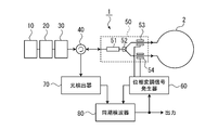
- FIG. 10 is a schematic block diagram for explaining the configuration of an optical fiber gyroscope using the optical fiber gyroscope light source device of the present invention.
- the parts having the same reference numerals as those in FIG. 1 and the like represent the same objects.
- the optical fiber gyroscope of the illustrated example can suppress thermal phase noise.
- the optical fiber gyroscope 1 uses the above-mentioned light source light source device for an optical fiber gyroscope (10, 20, 30) of the present invention as a light source.
- the optical fiber gyroscope 1 is driven by using the light composed of the continuous wide band spectrum generated by the light source device for the optical fiber gyroscope of the present invention.
- the optical fiber gyroscope 1 is mainly composed of an optical circulator 40, a multifunctional integrated optical circuit 50, a phase modulation signal generator 60, a photodetector 70, and a synchronous detector 80.
- the optical fiber coil 2 is connected to the multifunctional integrated optical circuit 50.
- the optical circulator 40 separates the light composed of a continuous wide band spectrum from the wide band section 30 and the interference light obtained by recombining the counterclockwise light and the clockwise light that have passed through the optical fiber coil 2. Is. That is, the optical circulator 40 outputs the light from the broadband section 30 to the multifunctional integrated optical circuit 50 side, which will be described later, and outputs the interference light to the photodetector 70 side when it returns to the optical circulator 40. It is a thing. In the drawing, light composed of a continuous wide band spectrum from the wide band section 30 is incident from the left side of the optical circulator 40, and this light is output from the right side of the optical circulator 40.
- the multifunctional integrated optical circuit 50 includes a polarizer 51, a Y-branch / recombination device 52, a first phase modulator 53, and a second phase modulator 54.
- the polarizer 51 is such that light composed of a continuous wide band spectrum from the wide band section 30 is incident through the optical circulator 40. Then, the polarizer 51 passes only a single polarized light.
- the Y-branch / recombination device 52 branches the incident light from the polarizer 51, that is, a single polarized light, and incidents light on both ends of the optical fiber coil 2. The light incident on both ends of the optical fiber coil 2 becomes counterclockwise light and clockwise light, respectively.
- the Y-branch / recombination device 52 recombines the counterclockwise light and the clockwise light that have passed through the optical fiber coil 2 and outputs this as interference light to the optical circulator 40.
- the first phase modulator 53 modulates one incident light incident on one end of the optical fiber coil 2. For example, the incident light that becomes clockwise light may be modulated.
- the second phase modulator 54 modulates the other incident light incident on the other end of the optical fiber coil 2. For example, the incident light that becomes counterclockwise light may be modulated.
- the phase modulation signal generator 60 generates a phase modulation signal in order to reduce thermal phase noise.
- the phase modulation signal generator 60 outputs a phase modulation signal to the first phase modulator 53 and the second phase modulator 54 of the multifunction integrated optical circuit 50.
- the phase modulation signal generator 60 generates a phase modulation signal for the multifunction integrated optical circuit 50 so as to perform phase modulation at an integral multiple of the natural frequency of the optical fiber coil 2. Specifically, for example, phase modulation may be performed so that the frequency is an integral multiple of about 10 to 100 times the natural frequency. This makes it possible to reduce the thermal phase noise.
- the optical detector 70 detects the light intensity signal of the interference light when the interference light between the left-handed light and the right-handed light that has passed through the optical fiber coil 2 is incident from the optical circulator 40.
- the synchronous detector 80 detects the input angular velocity with respect to the optical fiber coil 2 by using the phase modulated signal from the phase modulated signal generator 60 as a reference signal and synchronously detecting the light intensity signal detected by the optical detector 70. It is output as a signal.
- the optical fiber gyroscope using the light source device for an optical fiber gyroscope of the present invention reduces thermal phase noise by performing phase modulation at an integral multiple of the natural frequency of the optical fiber coil 2 by the above configuration. It becomes possible.
- FIG. 11 is a schematic block diagram for explaining another configuration of the optical fiber gyroscope using the light source device for the optical fiber gyroscope of the present invention.
- the parts with the same reference numerals as those in FIG. 10 represent the same products, and duplicate description will be omitted.
- the optical fiber gyroscope of the illustrated example is capable of suppressing relative intensity noise (RIN).
- the optical fiber gyroscope 1 of this example also uses light composed of a continuous wide band spectrum generated by the above-mentioned light source device for an optical fiber gyroscope (10, 20, 30) of the present invention.
- the optical fiber gyroscope 1 is driven.
- the optical fiber gyroscope 1 is mainly composed of an optical circulator 40, a multifunctional integrated optical circuit 50, a phase modulation signal generator 61, an optical detector 70, a photodetector 81, and a reference optical detector 90. It is configured in.
- the light composed of the continuous wide band spectrum from the wide band section 30 is output to the reference photodetector 90 side, which will be described later, in addition to the light directed to the optical circulator 40, by a beam splitter 45 or the like. It should be separated.
- the phase modulation signal generator 61 generates a phase modulation signal in order to reduce relative intensity noise.
- the phase modulation signal generator 61 outputs a phase modulation signal to the first phase modulator 53 and the second phase modulator 54 of the multifunction integrated optical circuit 50.
- the phase modulation signal generator 61 generates a phase modulation signal for the multifunction integrated optical circuit 50 so as to perform phase modulation at an odd multiple of the natural frequency of the optical fiber coil 2.
- phase modulation may be performed so as to have a frequency such as 1 time, 3 times, or 5 times the natural frequency. This makes it possible to reduce the relative intensity noise.
- the thermal phase noise can be reduced together with the relative intensity noise as in the example shown in FIG. That is, it is possible to reduce both thermal phase noise and relative intensity noise.
- the reference photodetector 90 detects a reference light intensity signal of light composed of a continuous broadband spectrum from the broadband section 30. That is, the reference photodetector 90 uses the light composed of the continuous wide band spectrum from the broadband section 30 as the reference light, and detects the reference light intensity signal.
- the synchronous detector 81 uses the phase modulation signal from the phase modulation signal generator 61 as a reference signal, and is the sum of the light intensity signal detected by the photodetector 70 and the reference light intensity signal detected by the reference light detector 90. By synchronously detecting the signal, it is output as a detection signal of the input angular velocity with respect to the optical fiber coil 2.
- the optical fiber gyroscope using the light source device for the optical fiber gyroscope of the present invention has the above-mentioned configuration and performs phase modulation at an odd multiple of the natural frequency of the optical fiber coil 2 to reduce relative intensity noise. Is possible. Further, if the phase modulation is performed by an odd multiple and an integer multiple, the thermal phase noise can be reduced together with the relative intensity noise.
- the phase modulation is performed at an odd multiple, and the sum signal of the light intensity signal by the photodetector 70 and the reference light intensity signal by the reference light detector 90 is synchronously detected.
- the phase modulation is performed at an even multiple.
- the difference signal between the light intensity signal by the photodetector 70 and the reference light intensity signal by the reference light detector 90 may be synchronously detected. That is, the phase modulation signal generator 61 may generate the phase modulation signal for the multifunction integrated optical circuit 50 so that the phase modulation is performed at an even multiple of the natural frequency of the optical fiber coil 2.
- the synchronous detector 81 may perform synchronous detection of the difference signal between the light intensity signal detected by the photodetector 70 and the reference light intensity signal detected by the reference light detector 90.
- the synchronous detector 80 shown in FIG. 10 and the synchronous detector 81 shown in FIG. 11 may use the phase-modulated signal from the phase-modulated signal generator 60 (61) as a reference signal for synchronous detection. .. Further, the signal that cancels the phase difference between the left-handed light and the right-handed light generated by the input angular velocity with respect to the optical fiber coil 2 is used as a feedback control signal for feedback control of the phase modulation signal generator 60 (61). It is also possible to output to the modulation signal generator 60 (61). This also makes it possible to increase the dynamic range of the input angular velocity.
- optical fiber gyroscope light source device of the present invention and the optical fiber gyroscope using the same are not limited to the above illustrated examples, and various modifications are made without departing from the gist of the present invention. Of course you can get it.
- Optical fiber gyroscope 2 Optical fiber coil 10
- Laser light source 20
- Stabilization unit 21
- SHG unit 22
- Atomic cell 30
- Broadband unit 31
- Optical comb generator 32
- White noise modulation unit 33
- Parametric downward conversion unit 40
- Optical circulator 50
- Multi-function integrated optical circuit 51
- Polarizer 52
- Branch / Recombinant 53
- 2nd Phase Modulator 60
- 61 Phase Modulation Signal Generator
- Optical Detector 80, 81 Synchronous Detector 90 Reference Optical Detector
Abstract
Priority Applications (4)
| Application Number | Priority Date | Filing Date | Title |
|---|---|---|---|
| US17/786,646 US20230030335A1 (en) | 2019-12-20 | 2020-11-19 | Light source device for fiber optic gyroscope and fiber optic gyroscope using the same |
| JP2021565392A JP7296151B2 (ja) | 2019-12-20 | 2020-11-19 | 光ファイバジャイロスコープ用光源装置及びそれを用いた光ファイバジャイロスコープ |
| AU2020408508A AU2020408508B2 (en) | 2019-12-20 | 2020-11-19 | Light source device for fiber optic gyroscope and fiber optic gyroscope using the same |
| EP20902358.9A EP4080163A4 (fr) | 2019-12-20 | 2020-11-19 | Dispositif de source de lumière pour gyroscope à fibre optique et gyroscope à fibre optique l'utilisant |
Applications Claiming Priority (2)
| Application Number | Priority Date | Filing Date | Title |
|---|---|---|---|
| JP2019-230925 | 2019-12-20 | ||
| JP2019230925 | 2019-12-20 |
Publications (1)
| Publication Number | Publication Date |
|---|---|
| WO2021124790A1 true WO2021124790A1 (fr) | 2021-06-24 |
Family
ID=76477220
Family Applications (1)
| Application Number | Title | Priority Date | Filing Date |
|---|---|---|---|
| PCT/JP2020/043273 WO2021124790A1 (fr) | 2019-12-20 | 2020-11-19 | Dispositif de source de lumière pour gyroscope à fibre optique et gyroscope à fibre optique l'utilisant |
Country Status (5)
| Country | Link |
|---|---|
| US (1) | US20230030335A1 (fr) |
| EP (1) | EP4080163A4 (fr) |
| JP (1) | JP7296151B2 (fr) |
| AU (1) | AU2020408508B2 (fr) |
| WO (1) | WO2021124790A1 (fr) |
Cited By (2)
| Publication number | Priority date | Publication date | Assignee | Title |
|---|---|---|---|---|
| JP7321621B1 (ja) * | 2022-07-28 | 2023-08-07 | 国立大学法人東京工業大学 | 光ファイバジャイロスコープ用光源装置 |
| JP7423118B1 (ja) | 2022-10-07 | 2024-01-29 | 国立大学法人東京工業大学 | 光ファイバジャイロスコープ用位相変調信号生成装置 |
Citations (8)
| Publication number | Priority date | Publication date | Assignee | Title |
|---|---|---|---|---|
| JPH03155686A (ja) | 1989-09-22 | 1991-07-03 | British Aerospace Plc <Baf> | リングレーザージャイロスコープ |
| JPH07324938A (ja) * | 1994-05-31 | 1995-12-12 | Tokimec Inc | 光ファイバジャイロ |
| JP2005172651A (ja) | 2003-12-12 | 2005-06-30 | Nippon Telegr & Teleph Corp <Ntt> | 光ジャイロ |
| JP2016017957A (ja) * | 2014-07-07 | 2016-02-01 | ハネウェル・インターナショナル・インコーポレーテッド | 高帯域幅レーザ安定化を備えた共通キャビティ長変調を使用する共振器光ファイバジャイロスコープ |
| JP2019522218A (ja) * | 2016-06-20 | 2019-08-08 | イクスブルー | 測定システム及びかかるシステムを含むジャイロスコープ |
| JP2019522817A (ja) * | 2016-06-24 | 2019-08-15 | エヌピーエル マネージメント リミテッド | 非相反光伝搬システムおよび方法 |
| JP2019529881A (ja) * | 2016-09-20 | 2019-10-17 | ザ ボード オブ トラスティーズ オブ ザ リーランド スタンフォード ジュニア ユニバーシティThe Board of Trustees of the Leland Stanford Junior University | 光学系およびホワイトノイズ変調を用いてレーザ駆動光源を利用する方法 |
| JP2019184599A (ja) | 2018-04-13 | 2019-10-24 | ノースロップ グラマン システムズ コーポレイションNorthrop Grumman Systems Corporation | 光ファイバジャイロ光源のための対称波長マルチプレクサ |
Family Cites Families (2)
| Publication number | Priority date | Publication date | Assignee | Title |
|---|---|---|---|---|
| GB2449290B (en) | 2007-05-17 | 2010-09-22 | Toshiba Res Europ Ltd | An optical system |
| JP2016017952A (ja) * | 2014-07-11 | 2016-02-01 | 株式会社東芝 | 超音波流量計 |
-
2020
- 2020-11-19 WO PCT/JP2020/043273 patent/WO2021124790A1/fr unknown
- 2020-11-19 EP EP20902358.9A patent/EP4080163A4/fr active Pending
- 2020-11-19 US US17/786,646 patent/US20230030335A1/en active Pending
- 2020-11-19 AU AU2020408508A patent/AU2020408508B2/en active Active
- 2020-11-19 JP JP2021565392A patent/JP7296151B2/ja active Active
Patent Citations (8)
| Publication number | Priority date | Publication date | Assignee | Title |
|---|---|---|---|---|
| JPH03155686A (ja) | 1989-09-22 | 1991-07-03 | British Aerospace Plc <Baf> | リングレーザージャイロスコープ |
| JPH07324938A (ja) * | 1994-05-31 | 1995-12-12 | Tokimec Inc | 光ファイバジャイロ |
| JP2005172651A (ja) | 2003-12-12 | 2005-06-30 | Nippon Telegr & Teleph Corp <Ntt> | 光ジャイロ |
| JP2016017957A (ja) * | 2014-07-07 | 2016-02-01 | ハネウェル・インターナショナル・インコーポレーテッド | 高帯域幅レーザ安定化を備えた共通キャビティ長変調を使用する共振器光ファイバジャイロスコープ |
| JP2019522218A (ja) * | 2016-06-20 | 2019-08-08 | イクスブルー | 測定システム及びかかるシステムを含むジャイロスコープ |
| JP2019522817A (ja) * | 2016-06-24 | 2019-08-15 | エヌピーエル マネージメント リミテッド | 非相反光伝搬システムおよび方法 |
| JP2019529881A (ja) * | 2016-09-20 | 2019-10-17 | ザ ボード オブ トラスティーズ オブ ザ リーランド スタンフォード ジュニア ユニバーシティThe Board of Trustees of the Leland Stanford Junior University | 光学系およびホワイトノイズ変調を用いてレーザ駆動光源を利用する方法 |
| JP2019184599A (ja) | 2018-04-13 | 2019-10-24 | ノースロップ グラマン システムズ コーポレイションNorthrop Grumman Systems Corporation | 光ファイバジャイロ光源のための対称波長マルチプレクサ |
Non-Patent Citations (1)
| Title |
|---|
| See also references of EP4080163A4 |
Cited By (4)
| Publication number | Priority date | Publication date | Assignee | Title |
|---|---|---|---|---|
| JP7321621B1 (ja) * | 2022-07-28 | 2023-08-07 | 国立大学法人東京工業大学 | 光ファイバジャイロスコープ用光源装置 |
| WO2024024032A1 (fr) * | 2022-07-28 | 2024-02-01 | 国立大学法人東京工業大学 | Dispositif de source de lumière de gyroscope à fibre optique |
| JP7423118B1 (ja) | 2022-10-07 | 2024-01-29 | 国立大学法人東京工業大学 | 光ファイバジャイロスコープ用位相変調信号生成装置 |
| WO2024075308A1 (fr) * | 2022-10-07 | 2024-04-11 | 国立大学法人東京工業大学 | Dispositif de génération de signal de modulation de phase pour gyroscope à fibre optique |
Also Published As
| Publication number | Publication date |
|---|---|
| JP7296151B2 (ja) | 2023-06-22 |
| AU2020408508B2 (en) | 2023-09-21 |
| EP4080163A1 (fr) | 2022-10-26 |
| AU2020408508A1 (en) | 2022-07-28 |
| EP4080163A4 (fr) | 2024-04-10 |
| US20230030335A1 (en) | 2023-02-02 |
| JPWO2021124790A1 (fr) | 2021-06-24 |
Similar Documents
| Publication | Publication Date | Title |
|---|---|---|
| US8514400B2 (en) | Optical gyroscope sensors based on optical whispering gallery mode resonators | |
| WO2015015628A1 (fr) | Dispositif de mesure de champ magnétique | |
| US8237514B2 (en) | Quantum interference device, atomic oscillator, and magnetic sensor | |
| US4856899A (en) | Optical frequency analyzer using a local oscillator heterodyne detection of incident light | |
| US20220221583A1 (en) | Ultra-low phase noise millimeter-wave oscillator and methods to characterize same | |
| JP6445468B2 (ja) | リング共振器を備えた光ファイバ干渉計測装置、かかる装置を含むジャイロメータ及び慣性姿勢又は航法ユニット | |
| JP2010505095A (ja) | 合成波長を生成する方法および装置 | |
| WO2021124790A1 (fr) | Dispositif de source de lumière pour gyroscope à fibre optique et gyroscope à fibre optique l'utilisant | |
| US20220260486A1 (en) | Chirped laser dispersion spectrometer and method | |
| JP5324332B2 (ja) | 光周波数コム安定化光源 | |
| JP2023157861A (ja) | 回転分光法によって規定された光ミリ波発振器 | |
| US20230318253A1 (en) | Ultra-high stability brillouin laser | |
| JP2012513617A (ja) | 周波数サーボが設けられたレーザーシステム | |
| JP6941121B2 (ja) | スペクトル狭小化モジュール、狭小化スペクトル線装置、及びそのための方法 | |
| JP2020503569A (ja) | テラヘルツレーザー源及びテラヘルツ放射を放出するための方法 | |
| JP2021189094A (ja) | 光ファイバジャイロスコープ用光源装置 | |
| JP6171256B2 (ja) | レーザ周波数安定化方法及びその装置 | |
| JP4956749B2 (ja) | 超高精度光位相同期システム | |
| KR20200032634A (ko) | 광섬유 지연 라인을 이용한 광주파수 안정화 장치, 그리고 안정화된 광주파수 신호 생성 방법 | |
| JP7423118B1 (ja) | 光ファイバジャイロスコープ用位相変調信号生成装置 | |
| JP7321621B1 (ja) | 光ファイバジャイロスコープ用光源装置 | |
| JP4547513B2 (ja) | 多重飽和分光によるレーザー周波数安定化装置 | |
| WO2023112186A1 (fr) | Dispositif de mesure de phase porteuse-enveloppe, source lumineuse stabilisée et procédé de mesure de phase porteuse-enveloppe | |
| US10317212B1 (en) | Enhancement of the phase response of intracavity phase interferometers | |
| Fang et al. | Frequency stabilization of semiconductor lasers |
Legal Events
| Date | Code | Title | Description |
|---|---|---|---|
| 121 | Ep: the epo has been informed by wipo that ep was designated in this application |
Ref document number: 20902358 Country of ref document: EP Kind code of ref document: A1 |
|
| ENP | Entry into the national phase |
Ref document number: 2021565392 Country of ref document: JP Kind code of ref document: A |
|
| NENP | Non-entry into the national phase |
Ref country code: DE |
|
| ENP | Entry into the national phase |
Ref document number: 2020902358 Country of ref document: EP Effective date: 20220720 |
|
| ENP | Entry into the national phase |
Ref document number: 2020408508 Country of ref document: AU Date of ref document: 20201119 Kind code of ref document: A |