WO2015012372A1 - ハイブリッド装置およびハイブリッドシステム - Google Patents
ハイブリッド装置およびハイブリッドシステム Download PDFInfo
- Publication number
- WO2015012372A1 WO2015012372A1 PCT/JP2014/069613 JP2014069613W WO2015012372A1 WO 2015012372 A1 WO2015012372 A1 WO 2015012372A1 JP 2014069613 W JP2014069613 W JP 2014069613W WO 2015012372 A1 WO2015012372 A1 WO 2015012372A1
- Authority
- WO
- WIPO (PCT)
- Prior art keywords
- cell stack
- fuel
- fuel cell
- manifold
- hybrid
- Prior art date
Links
Images


Classifications
-
- H—ELECTRICITY
- H01—ELECTRIC ELEMENTS
- H01M—PROCESSES OR MEANS, e.g. BATTERIES, FOR THE DIRECT CONVERSION OF CHEMICAL ENERGY INTO ELECTRICAL ENERGY
- H01M8/00—Fuel cells; Manufacture thereof
- H01M8/06—Combination of fuel cells with means for production of reactants or for treatment of residues
- H01M8/0606—Combination of fuel cells with means for production of reactants or for treatment of residues with means for production of gaseous reactants
- H01M8/0656—Combination of fuel cells with means for production of reactants or for treatment of residues with means for production of gaseous reactants by electrochemical means
-
- C—CHEMISTRY; METALLURGY
- C25—ELECTROLYTIC OR ELECTROPHORETIC PROCESSES; APPARATUS THEREFOR
- C25B—ELECTROLYTIC OR ELECTROPHORETIC PROCESSES FOR THE PRODUCTION OF COMPOUNDS OR NON-METALS; APPARATUS THEREFOR
- C25B1/00—Electrolytic production of inorganic compounds or non-metals
- C25B1/01—Products
- C25B1/02—Hydrogen or oxygen
- C25B1/04—Hydrogen or oxygen by electrolysis of water
-
- C—CHEMISTRY; METALLURGY
- C25—ELECTROLYTIC OR ELECTROPHORETIC PROCESSES; APPARATUS THEREFOR
- C25B—ELECTROLYTIC OR ELECTROPHORETIC PROCESSES FOR THE PRODUCTION OF COMPOUNDS OR NON-METALS; APPARATUS THEREFOR
- C25B15/00—Operating or servicing cells
- C25B15/08—Supplying or removing reactants or electrolytes; Regeneration of electrolytes
-
- C—CHEMISTRY; METALLURGY
- C25—ELECTROLYTIC OR ELECTROPHORETIC PROCESSES; APPARATUS THEREFOR
- C25B—ELECTROLYTIC OR ELECTROPHORETIC PROCESSES FOR THE PRODUCTION OF COMPOUNDS OR NON-METALS; APPARATUS THEREFOR
- C25B9/00—Cells or assemblies of cells; Constructional parts of cells; Assemblies of constructional parts, e.g. electrode-diaphragm assemblies; Process-related cell features
- C25B9/05—Pressure cells
-
- H—ELECTRICITY
- H01—ELECTRIC ELEMENTS
- H01M—PROCESSES OR MEANS, e.g. BATTERIES, FOR THE DIRECT CONVERSION OF CHEMICAL ENERGY INTO ELECTRICAL ENERGY
- H01M8/00—Fuel cells; Manufacture thereof
- H01M8/04—Auxiliary arrangements, e.g. for control of pressure or for circulation of fluids
- H01M8/04007—Auxiliary arrangements, e.g. for control of pressure or for circulation of fluids related to heat exchange
-
- H—ELECTRICITY
- H01—ELECTRIC ELEMENTS
- H01M—PROCESSES OR MEANS, e.g. BATTERIES, FOR THE DIRECT CONVERSION OF CHEMICAL ENERGY INTO ELECTRICAL ENERGY
- H01M8/00—Fuel cells; Manufacture thereof
- H01M8/04—Auxiliary arrangements, e.g. for control of pressure or for circulation of fluids
- H01M8/04223—Auxiliary arrangements, e.g. for control of pressure or for circulation of fluids during start-up or shut-down; Depolarisation or activation, e.g. purging; Means for short-circuiting defective fuel cells
- H01M8/04225—Auxiliary arrangements, e.g. for control of pressure or for circulation of fluids during start-up or shut-down; Depolarisation or activation, e.g. purging; Means for short-circuiting defective fuel cells during start-up
-
- H—ELECTRICITY
- H01—ELECTRIC ELEMENTS
- H01M—PROCESSES OR MEANS, e.g. BATTERIES, FOR THE DIRECT CONVERSION OF CHEMICAL ENERGY INTO ELECTRICAL ENERGY
- H01M8/00—Fuel cells; Manufacture thereof
- H01M8/04—Auxiliary arrangements, e.g. for control of pressure or for circulation of fluids
- H01M8/04223—Auxiliary arrangements, e.g. for control of pressure or for circulation of fluids during start-up or shut-down; Depolarisation or activation, e.g. purging; Means for short-circuiting defective fuel cells
- H01M8/04228—Auxiliary arrangements, e.g. for control of pressure or for circulation of fluids during start-up or shut-down; Depolarisation or activation, e.g. purging; Means for short-circuiting defective fuel cells during shut-down
-
- H—ELECTRICITY
- H01—ELECTRIC ELEMENTS
- H01M—PROCESSES OR MEANS, e.g. BATTERIES, FOR THE DIRECT CONVERSION OF CHEMICAL ENERGY INTO ELECTRICAL ENERGY
- H01M8/00—Fuel cells; Manufacture thereof
- H01M8/06—Combination of fuel cells with means for production of reactants or for treatment of residues
- H01M8/0606—Combination of fuel cells with means for production of reactants or for treatment of residues with means for production of gaseous reactants
- H01M8/0612—Combination of fuel cells with means for production of reactants or for treatment of residues with means for production of gaseous reactants from carbon-containing material
- H01M8/0618—Reforming processes, e.g. autothermal, partial oxidation or steam reforming
-
- H—ELECTRICITY
- H01—ELECTRIC ELEMENTS
- H01M—PROCESSES OR MEANS, e.g. BATTERIES, FOR THE DIRECT CONVERSION OF CHEMICAL ENERGY INTO ELECTRICAL ENERGY
- H01M8/00—Fuel cells; Manufacture thereof
- H01M8/24—Grouping of fuel cells, e.g. stacking of fuel cells
- H01M8/241—Grouping of fuel cells, e.g. stacking of fuel cells with solid or matrix-supported electrolytes
- H01M8/2425—High-temperature cells with solid electrolytes
- H01M8/2432—Grouping of unit cells of planar configuration
-
- H—ELECTRICITY
- H01—ELECTRIC ELEMENTS
- H01M—PROCESSES OR MEANS, e.g. BATTERIES, FOR THE DIRECT CONVERSION OF CHEMICAL ENERGY INTO ELECTRICAL ENERGY
- H01M8/00—Fuel cells; Manufacture thereof
- H01M8/24—Grouping of fuel cells, e.g. stacking of fuel cells
- H01M8/2457—Grouping of fuel cells, e.g. stacking of fuel cells with both reactants being gaseous or vaporised
-
- H—ELECTRICITY
- H01—ELECTRIC ELEMENTS
- H01M—PROCESSES OR MEANS, e.g. BATTERIES, FOR THE DIRECT CONVERSION OF CHEMICAL ENERGY INTO ELECTRICAL ENERGY
- H01M8/00—Fuel cells; Manufacture thereof
- H01M8/24—Grouping of fuel cells, e.g. stacking of fuel cells
- H01M8/2465—Details of groupings of fuel cells
- H01M8/2484—Details of groupings of fuel cells characterised by external manifolds
- H01M8/2485—Arrangements for sealing external manifolds; Arrangements for mounting external manifolds around a stack
-
- Y—GENERAL TAGGING OF NEW TECHNOLOGICAL DEVELOPMENTS; GENERAL TAGGING OF CROSS-SECTIONAL TECHNOLOGIES SPANNING OVER SEVERAL SECTIONS OF THE IPC; TECHNICAL SUBJECTS COVERED BY FORMER USPC CROSS-REFERENCE ART COLLECTIONS [XRACs] AND DIGESTS
- Y02—TECHNOLOGIES OR APPLICATIONS FOR MITIGATION OR ADAPTATION AGAINST CLIMATE CHANGE
- Y02E—REDUCTION OF GREENHOUSE GAS [GHG] EMISSIONS, RELATED TO ENERGY GENERATION, TRANSMISSION OR DISTRIBUTION
- Y02E60/00—Enabling technologies; Technologies with a potential or indirect contribution to GHG emissions mitigation
- Y02E60/30—Hydrogen technology
- Y02E60/36—Hydrogen production from non-carbon containing sources, e.g. by water electrolysis
-
- Y—GENERAL TAGGING OF NEW TECHNOLOGICAL DEVELOPMENTS; GENERAL TAGGING OF CROSS-SECTIONAL TECHNOLOGIES SPANNING OVER SEVERAL SECTIONS OF THE IPC; TECHNICAL SUBJECTS COVERED BY FORMER USPC CROSS-REFERENCE ART COLLECTIONS [XRACs] AND DIGESTS
- Y02—TECHNOLOGIES OR APPLICATIONS FOR MITIGATION OR ADAPTATION AGAINST CLIMATE CHANGE
- Y02E—REDUCTION OF GREENHOUSE GAS [GHG] EMISSIONS, RELATED TO ENERGY GENERATION, TRANSMISSION OR DISTRIBUTION
- Y02E60/00—Enabling technologies; Technologies with a potential or indirect contribution to GHG emissions mitigation
- Y02E60/30—Hydrogen technology
- Y02E60/50—Fuel cells
Definitions
- the present invention relates to a hybrid device including an electrolytic cell stack device and a fuel cell stack device, and a hybrid system including the same.
- Patent Document 1 merely describes a combination of a solid oxide fuel cell (SOFC) and a solid oxide electrolytic cell (SOEC) as a block diagram. There is no suggestion of a simple configuration, and a more efficient one is required.
- SOFC solid oxide fuel cell
- SOEC solid oxide electrolytic cell
- an object of the present invention is to provide a more efficient hybrid device and a hybrid system including the same in a hybrid device in which an electrolytic cell stack device and a fuel cell stack device are combined.
- the hybrid device of the present invention includes an electrolysis cell stack device having an electrolysis cell stack having a plurality of electrolysis cells for generating a gas containing hydrogen from a gas containing water vapor, and a fuel having a fuel cell stack having a plurality of fuel cells.
- steam to supply is arrange
- a hybrid system of the present invention includes the above-described hybrid device and an auxiliary device for supplying a gas containing oxygen or water vapor to the manifold of the fuel cell stack device.
- the hybrid system of the present invention stops the supply of current to the external load of the fuel cell stack device and the temperature of the fuel cell in the hybrid device and the operation stop processing of the hybrid device.
- a control device is provided for controlling the supply of current to the electrolysis cell stack device and the supply of water to the vaporizer to be stopped after a predetermined temperature or lower.
- the hybrid device of the present invention can efficiently supply water vapor to the electrolytic cell stack device, improve the temperature distribution of the fuel cell stack device, and improve the power generation efficiency. Can do.
- the hybrid system of the present invention can be a hybrid system with improved reliability.
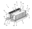
- FIG. 1 is an external perspective view showing an example of the hybrid apparatus of the present embodiment.
- the same thing shall be demonstrated using the same code
- the hybrid device 1 of the present embodiment includes a solid oxide electrolytic cell stack device 2 and a solid oxide fuel cell stack device 3.
- water vapor is supplied and a current is passed through the electrolysis cell stack device 2 (a voltage is applied) to cause an electrolysis reaction and generate a gas containing hydrogen.
- the fuel cell stack device 3 by supplying a gas containing hydrogen which is a fuel gas, a power generation reaction occurs and electric power can be obtained.
- the electrolysis cell stack device 2 includes an electrolysis cell stack 5 arranged in a row and electrically connected in a state where a plurality of electrolysis cells 4 are erected, and the electrolysis cell 4 constituting the electrolysis cell stack 5
- One end portion (lower end portion) is an insulating bonding material (not shown) such as a glass sealing material, and is fixed to the first manifold 6 made of metal or the like.
- end conductive members 8 having conductive portions 9 for flowing a current through the electrolytic cell stack 5 (electrolytic cell 4) are arranged.
- the other end (upper end) of the electrolysis cell stack 5 (the plurality of electrolysis cells 4) is an insulating bonding material (not shown) such as a glass sealing material, and is a second manifold formed of metal or the like. 7 is fixed.
- the gas containing hydrogen generated by the electrolysis reaction supplied to the electrolysis cell 4 is recovered by the second manifold 7. That is, the second manifold 7 itself is a collection unit.
- the gas containing hydrogen recovered in the second manifold 7 is led out to the outside through the gas lead-out pipe 18 and is supplied to the fuel cell stack device 3 arranged adjacent to the gas introduction pipe 19.
- the second manifold 7 of the electrolysis cell stack apparatus 2 and the manifold 12 of the fuel cell stack apparatus 3 described later are connected by the gas introduction pipe 19. Accordingly, at least a part of the gas containing hydrogen generated in the electrolytic cell stack device 2 is supplied to the fuel cell stack device 3.
- the gas outlet pipe 18 or the gas inlet pipe 19 is appropriately provided with a valve. By controlling the operation of this valve, the gas containing hydrogen is led out to the outside.
- the fuel cell stack device 3 can be supplied.
- the electrolysis cell shown in FIG. Note that a conductive member may be disposed between the electrolysis cells 4 for the purpose of facilitating current flow through the electrolysis cells 4.
- the fuel cell stack device 3 includes a fuel cell stack 11 arranged in a row in a state where a plurality of fuel cells 10 are erected, and electrically connected via a current collecting member, One end (lower end) of the fuel cell 10 constituting the fuel cell stack 11 is fixed to a manifold 12 made of metal or the like with an insulating bonding material (not shown) such as a glass seal material. .
- a manifold 12 made of metal or the like with an insulating bonding material (not shown) such as a glass seal material.
- end current collecting members 13 having current extraction portions 14 for deriving current generated by the fuel cell stack 11 (fuel cell 10) are disposed. Yes.
- a vertically striped fuel cell 10 is provided as the fuel cell shown in FIG.
- a gas containing hydrogen (a gas containing hydrogen) and an oxygen-containing gas are supplied to the fuel cell 10, and the hydrogen supplied to the fuel cell 10 is heated by heating the fuel cell 10 to 600 to 1000 ° C.
- the gas containing oxygen and the oxygen-containing gas undergo a reaction represented by the following reaction formula between the cathode and the anode, and electric power can be obtained.
- the gas containing hydrogen that has not been used for power generation is burned on the other end side (upper end side) of the fuel cell 10, so that the temperature of the fuel cell stack 11 is increased or increased by the combustion heat. It can also be maintained.
- Anode H 2 + O 2 ⁇ ⁇ H 2 O + 2e ⁇
- the electrolytic cell stack device 2 and the fuel cell stack device 3 are largely different in that the second manifold 7 is arranged above the electrolytic cell stack device 2 with respect to the configuration.
- a vaporizer 16 for generating water vapor to be supplied to the first manifold 6 of the electrolysis cell stack apparatus 2 is disposed in the vicinity of the fuel cell stack 11.
- the carburetor 16 is disposed at the center along the arrangement direction of the fuel cells 10. Specifically, in the fuel cell stack 11 shown in FIG. Although it is arrange
- a water introduction pipe 15 for introducing water supplied from the water supply device into the vaporizer 16 is connected to the upper end of the vaporizer 16, while one end of the vaporizer 16 is connected to the lower end side.
- a water vapor inflow pipe 17 is connected to the first manifold 6 at the other end.
- a temperature distribution may occur with power generation.
- this temperature distribution can be improved, and the power generation efficiency of the fuel cell stack device 3 is suppressed from decreasing, in other words, power generation. Efficiency can be improved.
- FIG. 1 shows an example in which the vaporizer 16 is disposed between the electrolytic cell stack device 2 and the fuel cell stack device 3, the vaporizer 16 may be in the vicinity of the fuel cell stack device 3. For example, it can also be provided on the side opposite to the electrolytic cell stack device 2.
- the electrolytic cell 4 contains Ni
- Ni may be oxidized by the water vapor.
- the Ni-containing support and the inner electrode layer (cathode) cause a volume change due to oxidation, and excessive stress is generated in the solid electrolyte, thereby destroying the solid electrolyte.
- a cross leak of the solid electrolyte occurs, and the performance of the electrolytic cell 4 is greatly deteriorated. Therefore, in order to avoid this, the oxidation of the electrolytic cell 4 can be suppressed by supplying a smaller amount of hydrogen in addition to the water vapor.
- a fuel supply pipe 20 for supplying raw fuel or a gas containing hydrogen is connected to the manifold 12 of the fuel cell stack device 3 shown in FIG.
- the fuel supply pipe 20 only needs to be able to supply the raw fuel directly or indirectly to the manifold 12.
- the water introduction pipe 15 is a double pipe with the fuel supply pipe 20, and the vaporizer 16, steam inflow You may make it supply to the manifold 12 through the pipe
- a reformer may be provided above the fuel cell stack device 3 and the fuel supply pipe 20 may be connected to the reformer and supplied to the manifold 12 via the reformer. Good.
- the raw fuel a hydrocarbon gas can be exemplified.
- electrolysis cell 4 electrolysis cell stack 5
- fuel cell 10 fuel cell stack 11
- FIG. 2A is a plan view showing a part of the electrolytic cell stack apparatus extracted from the hybrid apparatus of the present embodiment.
- FIG. 2B is a plan view showing a part of the fuel cell stack apparatus.
- the electrolytic cell 4 and the fuel battery cell 10 can use cells having substantially the same configuration, and therefore, each cell will be described using the electrolytic cell 4.
- the fuel battery cell 10 will also be described only when there is a difference between the battery cell 10 and the battery cell 10.
- the electrolysis cell 4 is a hollow flat plate type, has a flat cross section, and is a porous conductive support body (hereinafter referred to as a support body) having an elliptical columnar shape as a whole. 21).
- a plurality of flow holes 26 are formed at appropriate intervals so as to penetrate from the one end to the other end along the length direction of the electrolysis cell 4.
- 21 has a structure in which various members are provided.
- the flow hole 26 is preferably circular or elliptical in the cross section of the electrolysis cell 4.
- the support 21 is composed of a pair of parallel flat surfaces n and side surfaces (arc-shaped portions) m connecting both ends of the pair of flat surfaces n. It is configured. Both surfaces of the flat surface n are formed substantially in parallel with each other, and a porous inner electrode layer 22 (cathode) is provided so as to cover one surface of the flat surface n and both side surfaces m.
- a dense solid electrolyte layer 23 is laminated so as to cover the inner electrode layer 22.
- a porous outer electrode layer 24 (anode) is laminated on the solid electrolyte layer 23 so as to face the inner electrode layer 22, and the inner electrode layer 22, the solid electrolyte layer 23, and the outer electrode layer are laminated. The part where 24 overlaps becomes an electrolytic element part.
- An interconnector 25 is laminated on the other flat surface n on which the inner electrode layer 22 and the solid electrolyte layer 23 are not laminated.
- the inner electrode layer 22 functions as an anode and the outer electrode layer 24 functions as a cathode.
- a portion where the inner electrode layer 22, the solid electrolyte layer 23, and the outer electrode layer 24 are overlapped becomes a power generation element portion.
- the solid electrolyte layer 23 (and the inner electrode layer 22) extends to the other flat surface n side via an arc-shaped side surface m connecting both ends of the flat surface n.
- Both end surfaces of the interconnector 25 are in contact with both end surfaces of the inner electrode layer 22 and the solid electrolyte layer 23. Note that both end portions of the interconnector 25 may be disposed so as to be stacked on both end portions of the solid electrolyte layer 23.
- An adhesive layer for firmly joining the interconnector 25 and the support 21 can be provided between the interconnector 25 and the support 21, and the solid electrolyte layer 23 and the outer electrode layer 24 can be provided.
- a reaction preventing layer for suppressing the reaction of the components of the solid electrolyte layer 23 and the outer electrode layer 24 to produce a reaction product having a high resistance can be provided.
- water vapor is caused to flow through the flow hole 26 in the support 21 and heated to the above-described predetermined operating temperature, and the predetermined electrode described above is interposed between the inner electrode layer 22 and the outer electrode layer 24.
- a voltage By applying a voltage, an electrolytic reaction can occur.
- the voltage is applied by passing a current through the electrolytic cell 4 via the interconnector 25 stacked on the support 21.
- a power generation reaction can be caused by flowing a gas containing hydrogen through the flow hole 26 in the support 21 and reaching the predetermined operating temperature described above.
- the current generated by the power generation flows to the adjacent fuel cell 10 via the current collecting member 27 via the interconnector 25 laminated on the support 21.
- a current collecting member 27 having a space through which an oxygen-containing gas flows is disposed between the fuel cells 10.
- the current collecting member 27 and the interconnector 25 are joined via a conductive adhesive 28.
- the support 21 has conductivity that allows gas containing water vapor and hydrogen to pass through to the solid electrolyte layer 23, and is electrically conductive because current flows through the interconnector 25. Since it is required, for example, it is preferably formed of an iron group metal component and a specific inorganic oxide (for example, rare earth element oxide).
- the iron group metal component examples include an iron group metal element, an iron group metal oxide, an iron group metal alloy or an alloy oxide, and the like. More specifically, for example, Fe, Ni and Co can be used as the iron group metal, and since it is particularly inexpensive, it contains Ni and / or NiO as the iron group component / iron group metal oxide. Preferably it is. In addition to Ni and / or NiO, Fe or Co may be contained. NiO is reduced by H 2 generated by the electrolytic reaction, and part or all of it is present as Ni.
- the rare earth element oxide is used to bring the thermal expansion coefficient of the support 21 close to the thermal expansion coefficient of the solid electrolyte layer 23.
- Rare earth element oxides containing at least one element selected from the group consisting of Gd, Sm, and Pr can be used in combination with the iron group component.
- Specific examples of such rare earth element oxides include Y 2 O 3 , Lu 2 O 3 , Yb 2 O 3 , Tm 2 O 3 , Er 2 O 3 , Ho 2 O 3 , Dy 2 O 3 , Gd 2.
- the iron group metal component and the rare earth element oxide component have a volume after firing-reduction in that the good conductivity of the support 21 is maintained and the thermal expansion coefficient is approximated to that of the solid electrolyte layer 23. It is preferably present in a volume ratio of 35:65 to 65:35.
- the Ni as an iron-group metal component when used Y 2 O 3 as the rare earth element oxide component is preferably Ni / (Ni + Y) contains such a 79-93 mol%.
- the support 21 may contain other metal components and oxide components as long as required properties are not impaired.
- the support 21 needs to have water vapor permeability, it is usually preferable that the open porosity is 30% or more, particularly 35 to 50%.
- the conductivity of the support 21 is 50 S / cm or more, more preferably 300 S / cm or more, and particularly preferably 440 S / cm or more.
- the length of the flat surface n of the support 21 (length in the width direction of the support 21) is usually 15 to 35 mm, and the length of the side surface m (arc length) is 2 to 8 mm.
- the thickness of the support 21 (thickness between both surfaces of the flat surface n) is preferably 1.5 to 5 mm.
- the inner electrode layer 22 causes an electrode reaction and is preferably formed of a known porous conductive ceramic.
- a known porous conductive ceramic for example, it can be formed from ZrO 2 in which a rare earth element oxide is dissolved or CeO 2 in which a rare earth element oxide is dissolved, and Ni and / or NiO.
- the rare earth element the rare earth element exemplified in the support 21 can be used, and for example, it can be formed from ZrO 2 (YSZ) in which Y 2 O 3 is dissolved and Ni and / or NiO.
- the content of ZrO 2 in which the rare earth element oxide in the inner electrode layer 22 is dissolved or the content of CeO 2 in which the rare earth element oxide is dissolved and the content of Ni or NiO are volume ratios after firing-reduction, It is preferably present in a volume ratio of 35:65 to 65:35.
- the open porosity of the inner electrode layer 22 is preferably 15% or more, particularly preferably in the range of 20 to 40%, and the thickness thereof is preferably 1 to 30 ⁇ m. For example, if the thickness of the inner electrode layer 22 is too thin, the performance may be deteriorated, and if it is too thick, peeling due to a difference in thermal expansion between the solid electrolyte layer 23 and the inner electrode layer 22 may occur. .
- the inner electrode layer 22 is positioned from one flat surface n (flat surface n located on the left side in the drawing) to the other flat surface n (right side in the drawing) via the side surface m.
- the inner electrode layer 22 may be formed only on the flat surface n on the side where the outer electrode layer 24 is provided, for example, since it only needs to be formed at a position facing the outer electrode layer 24. May be formed. That is, the inner electrode layer 22 is provided only on the flat surface n, and the solid electrolyte layer 23 is formed on the inner electrode layer 22, both side surfaces m, and the other flat surface n where the inner electrode layer 22 is not formed. It may have a structure.
- the solid electrolyte layer 23 is made of a dense ceramic made of partially stabilized or stabilized ZrO 2 containing 3 to 15 mol% of a rare earth element oxide such as Y 2 O 3 , Sc 2 O 3 , Yb 2 O 3. It is preferable to use it. As the rare earth element, Y is preferable because it is inexpensive. Further, the solid electrolyte layer 23 is desirably a dense material having a relative density (according to Archimedes method) of 93% or more, particularly 95% or more, and has a thickness of 5 to 50 ⁇ m from the viewpoint of preventing water vapor transmission. It is preferable that
- the solid electrolyte layer 23 and the outer electrode layer 24 are firmly joined between the solid electrolyte layer 23 and the outer electrode layer 24 described later, and the components of the solid electrolyte layer 23 and the outer electrode layer 24 are It is also possible to provide a reaction preventing layer for the purpose of suppressing the reaction with the above components to produce a reaction product having a high electrical resistance.
- the reaction preventing layer can be formed of a composition containing Ce (cerium) and other rare earth elements.
- Ce cerium
- REO 1.5 rare earth elements
- RE is Sm, Y , Yb, and Gd
- x preferably has a composition represented by a number satisfying 0 ⁇ x ⁇ 0.3.
- Sm or Gd as RE.
- 10 to 20 mol% of SmO 1.5 or GdO 1.5 contains CeO 2 as a solid solution. Is preferred.
- the solid electrolyte layer 23 and the outer electrode layer 24 are firmly bonded, and further, the reaction of the components of the solid electrolyte layer 23 and the components of the outer electrode layer 24 to generate a reaction product having a high electric resistance is further suppressed.
- the reaction preventing layer may be formed of two layers.
- the outer electrode layer 24 is preferably formed of a conductive ceramic made of a so-called ABO 3 type perovskite oxide.
- a perovskite oxide is preferably a transition metal perovskite oxide, in particular at least one of LaMnO 3 oxide, LaFeO 3 oxide, and LaCoO 3 oxide in which Sr and La coexist at the A site. 600 LaCoO 3 -based oxides are particularly preferred because of their high electrical conductivity at an operating temperature of about 1000 ° C.
- Sr and La may exist at the A site, and Fe (iron) and Mn (manganese) may exist along with Co (cobalt) at the B site.
- the outer electrode layer 24 needs to be permeable to oxygen gas. Therefore, the conductive ceramic (perovskite oxide) forming the outer electrode layer 24 has an open porosity of 20% or more, particularly 30 to 30%. It is preferable to be in the range of 50%. Further, the thickness of the outer electrode layer 24 is preferably 30 to 100 ⁇ m from the viewpoint of conductivity of the electrolytic cell 4 and the fuel cell 10.
- an interconnector 25 is laminated on the flat surface n opposite to the outer electrode layer 24 side of the support 21.
- the interconnector 25 is preferably formed of conductive ceramics, but needs to have reduction resistance and oxidation resistance in order to come into contact with a fluid containing hydrogen and a fluid containing oxygen. For this reason, it is generally preferable to use a lanthanum chromite-based perovskite oxide (LaCrO 3 -based oxide) as the conductive ceramic having reduction resistance and oxidation resistance. Furthermore, it is preferable to use a LaCrMgO 3 -based oxide in which Mg is present at the B site, particularly for the purpose of bringing the thermal expansion coefficients of the support 21 and the solid electrolyte layer 23 closer. The amount of Mg can be adjusted as appropriate so that the thermal expansion coefficient of the interconnector 25 approaches the thermal expansion coefficients of the support 21 and the solid electrolyte layer 23, specifically, 10 to 12 ppm / K. it can.
- LaCrMgO 3 -based oxide lanthanum chromite-based perovskite oxide
- an adhesion layer for reducing a difference in thermal expansion coefficient between the interconnector 25 and the support 21 can be provided between the support 21 and the interconnector 25.
- Such an adhesion layer may have a composition similar to that of the inner electrode layer 22.
- it can be formed from at least one of rare earth element oxide, ZrO 2 in which a rare earth element oxide is dissolved, and CeO 2 in which a rare earth element oxide is dissolved, and Ni and / or NiO.
- a composition composed of Y 2 O 3 and Ni and / or NiO, a composition composed of ZrO 2 (YSZ) in which Y 2 O 3 is dissolved, and Ni and / or NiO, Y, Sm, Gd It can be formed from a composition composed of CeO 2 and Ni and / or NiO in which an oxide such as oxide is dissolved.
- the content of ZrO 2 in which the rare earth element oxide is dissolved or the content of CeO 2 in which the rare earth element oxide is dissolved and the content of Ni or NiO are 40:60 to It is preferably present in a volume ratio of 60:40.
- the outer electrode layer 24 of the other adjacent electrolytic cell 4 is joined to the interconnector 25 of the one electrolytic cell 4, whereby the electrolytic cells 4 are connected to each other. Are electrically connected. It is sufficient that the interconnector 25 of one electrolytic cell 4 and the outer electrode layer 24 of the other electrolytic cell 4 are electrically connected.
- a current collecting member (conductive member) shown in FIG. ) 27 may be electrically connected.
- the electrolytic cell 4 in which the outer electrode layer 24 is not formed is used, the paste constituting the outer electrode layer 24 is applied to the interconnector 25 of one electrolytic cell 4, and the other adjacent The interconnector 25 of one adjacent electrolytic cell 4 is applied to the solid electrolyte layer 23 of the electrolytic cell 4 by applying the paste for forming the outer electrode layer 24, attaching the surfaces coated with the paste to each other, and performing heat treatment. And the outer electrode layer 24 of the other electrolytic cell 4 can be directly joined and electrically connected.
- the outer electrode layer 24 Since the outer electrode layer 24 has a predetermined porosity as described above, many pores communicate with each other, a gas passage is formed in the outer electrode layer 24, and oxygen generated by the electrolytic reaction is reduced. The gas can be discharged out of the outer electrode layer 24 through the gas passage formed in the outer electrode layer 24. With a simpler structure, the gas from the electrolysis cell 4 can be discharged, and a plurality of electrolysis cells 4 can be electrically connected. Can be connected.
- the conductive adhesive 28 that joins the interconnector 25 and the current collecting member 27 of one fuel cell 10 has conductivity.
- it may be made of the same material as that of the outer electrode layer 28.
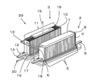
- FIG. 3 is an external perspective view showing another example of the hybrid device of the present embodiment.
- the carburetor 16 is a central portion along the arrangement direction of the fuel cells 10 in the fuel cell stack device 3 and the fuel as compared with the hybrid device 1 shown in FIG. 1. It differs in that it is arranged above the battery cell 10.
- the carburetor 16 By disposing the carburetor 16 above the fuel cell 10, the carburetor 16 can be efficiently supplied to the carburetor 16 by combustion heat generated by burning a gas containing hydrogen that has not been used for power generation above the fuel cell 10.
- the supplied water can be vaporized into water vapor. Thereby, water vapor can be efficiently supplied to the electrolytic cell stack device 2.
- the vaporizer 16 at the central portion along the arrangement direction of the fuel cells 10 in the fuel cell stack device 3, the temperature of the center portion of the fuel cell stack device 3 can be lowered, and the temperature distribution is improved. Therefore, power generation efficiency can be improved.
- FIG. 4 is an external perspective view showing still another example of the hybrid device of the present embodiment
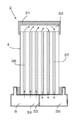
- FIG. 5 is a cross-sectional view of the electrolytic cell stack device constituting the hybrid device shown in FIG.
- the water vapor supplied to the first manifold 6 flows through the flow hole 26 of the electrolysis cell 4 from one end (lower end) to the other end (upper end), so that the second manifold 7, in the hybrid device 30 shown in FIG. 4, the electrolysis cell 4 has two or more flow holes 26, and one flow hole 26 is the forward flow hole 36.
- the other flow hole 26 is a return-side flow hole 37 and is folded back by the electrolysis cell 4 via the second manifold 31.
- the second manifold 31 causes the fluid that has flowed through the forward-side flow hole 36 to flow to the return-side flow hole 37 at the other end (upper end) of the electrolysis cell 4 shown in FIG. 1.
- a space 32 is provided.
- the left side in FIG. 5 is a fluid (mainly gas containing water vapor) supply unit 34, and the right side is a fluid (mainly hydrogen containing gas) recovery unit 35. These are partitioned by a partition member 33.
- the gas containing hydrogen generated by the electrolytic reaction and water vapor not used for the reaction flows to the space 32 of the second manifold 31 from the upper side of the forward-side flow hole 36 continuously. That is, the second manifold 31 is a manifold through which a gas containing hydrogen flows.
- the fluid that has flowed into the space 32 then flows into the return-side circulation hole 37 and flows downward through the return-side circulation hole 37.
- the lower end of the return-side flow hole 37 communicates with the collection unit 35.
- the air flows through the space 32 to the return-side flow hole 37, flows downward through the return-side flow hole 37, and then flows to the collection unit 35. Therefore, the gas containing hydrogen can be efficiently recovered by recovering the fluid that has flowed to the recovery unit 35.
- the first manifold 6 of the electrolysis cell stack device 2 includes a supply unit to which water vapor is supplied and a manifold having a recovery unit that recovers a gas containing hydrogen. . Even during the downward flow through the return-side flow hole 37, some or all of the water vapor that has not undergone the reaction contained in the fluid undergoes an electrolytic reaction, and hydrogen can be generated.
- the hatched portion on the upper surface of the first manifold 6 in FIG. 5 indicates an insulating bonding agent that fixes the electrolytic cell 4 and the first manifold 6.
- the inner surface of the second manifold 31 may be arcuate so that the gas containing hydrogen that has flown through the forward-side flow hole 36 flows efficiently into the return-side flow hole 37.
- the second manifold 31 may cover the entire electrolytic cell stack 5 or may be provided at the upper end of each electrolytic cell 4.
- the efficient hybrid apparatus since the gas containing hydrogen can be efficiently generated in the electrolytic cell stack apparatus 2 and the power generation can be performed efficiently in the fuel cell stack apparatus 3, the efficient hybrid apparatus It can be.
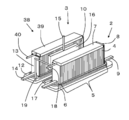
- FIG. 6 is an external perspective view showing still another example of the hybrid device of the present embodiment.
- the fuel cell stack device 3 the other end of the fuel cell stack is compared with the hybrid device 1 shown in FIG. The difference is that a reformer 39 for reforming the raw fuel is provided in the vicinity of the side.
- a part of the gas containing hydrogen generated by the electrolysis cell stack device 2 can be supplied to the fuel cell stack device 3, but a gas containing a lot of hydrogen according to external requirements. May be extracted to the outside and the amount of gas containing hydrogen that can be supplied to the fuel cell stack device 3 may be reduced. Therefore, in the fuel cell stack device 3, the reformer 39 for reforming the raw fuel is provided in the vicinity of the other end side of the fuel cell stack, so that the power generation of the fuel cell stack device 3 is stably continued. be able to. Thereby, the hybrid device 38 with further improved efficiency can be obtained.
- the reformer 39 is preferably a reformer capable of performing steam reforming with high reforming efficiency, and the reformer 39 includes a vaporization section that vaporizes water and a reforming catalyst. A configuration having a reforming section is preferable.
- the reformer 39 is connected to a raw fuel supply pipe 40 for supplying raw fuel such as hydrocarbon gas.
- the temperature of the reformer 39 can be efficiently increased by the combustion heat generated by fueling the gas containing surplus hydrogen that has not been used for power generation above the fuel cell 10. In addition to shortening the startup time of 39, the reforming efficiency can be improved.
- the reformer 39 capable of steam reforming and the vaporizer 16 are configured differently.
- the reformer 39 also serves as a vaporizer of the reformer 39. It can also be set as the structure which supplies water vapor
- a gas containing hydrogen generated by the reforming reaction in the reformer 39 is a fuel supply pipe that connects the reformer 39 and the manifold 12 of the fuel cell stack device 3. Is supplied to the manifold 12. At the time of start-up, the raw fuel supplied until the reforming reaction of the reformer 39 is started is supplied to the manifold 12 as it is, and after passing through the fuel battery cell 10, the fuel battery cell 10 Will be burned above. Therefore, the fuel supply pipe that connects the reformer 39 and the manifold 12 of the fuel cell stack device 3 serves as the fuel supply pipe 20 shown in FIG.
- a gas containing hydrogen flows, so that the inner surfaces of the second manifolds 7 and 31 are connected to the other end (upper end) of the electrolysis cell 4. It is preferable that the shape has a predetermined distance.
- first manifold 6 and the second manifolds 7 and 31 can be made of a heat-resistant material, for example, ceramic or metal.
- first manifold 6 and the second manifolds 7 and 31 are made of metal
- the first manifold 6 and the second manifolds 7 and 31 and the electrolysis cell 4 are preferably insulated. Therefore, for example, it is preferable that the first manifold 6 and the second manifolds 7 and 31 and the electrolysis cell 4 are arranged with a gap therebetween and fixed with an insulating adhesive such as glass.
- an insulating or annular member is disposed at the other end (upper end) of the electrolysis cell 4. It is preferable to insulate the second manifold 7, 31 and the electrolytic cell 4 by applying an insulating coating on the inner surface of the second manifold 7, 31. Thereby, it is possible to suppress leakage of fluid such as gas containing water vapor or hydrogen flowing through the flow hole 26 while ensuring insulation between the first manifold 6 and the second manifold 7 and 31 and the electrolytic cell 4. . In the case where an insulating or annular member is disposed between the second manifolds 7 and 31 and the electrolysis cell 4, the annular or tubular inner side becomes the space 32.
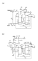
- FIG. 7 is a block diagram illustrating a part of the configuration of a hybrid system including the hybrid apparatus according to the present embodiment.
- FIG. 7A illustrates a part of the hybrid apparatus 1 illustrated in FIG. (B) extracts and shows a part of the hybrid device 38 shown in FIG.
- the fuel supply pipe 20 is connected to the manifold 12 of the fuel cell stack apparatus, and a fuel pump 42 is provided upstream thereof.
- the oxygen-containing gas includes an oxygen-containing gas flow passage 47 that supplies the oxygen-containing gas to the outer electrode layer of the fuel cell 10 and an oxygen-containing gas supply pipe 48 that is connected to the first manifold 12.
- an oxygen-containing gas supply device (blower) 41 is connected upstream of these.
- FIG. 7 shows an example in which an oxygen-containing gas flows from one oxygen-containing gas supply device 41 to the oxygen-containing gas flow passage 47 and the oxygen-containing gas supply pipe 48, but one oxygen-containing gas supply is provided for each.
- the apparatus 41 may be provided. In the manifold 12, water vapor may be supplied instead of the oxygen-containing gas.
- a water pump 43 that is a water supply device is provided upstream of the water supply pipe 15 that supplies water to the vaporizer 16. Thereby, water can be appropriately supplied to the vaporizer 16. Further, the vaporizer 16 and the first manifold 6 of the electrolytic cell stack apparatus are connected by a water vapor inflow pipe 17.
- the second manifold 7 includes a gas outlet pipe 18 for leading the gas containing hydrogen generated in the electrolysis cell stack apparatus 5 to the outside, and a gas introduction pipe for flowing to the manifold 12 of the fuel cell stack apparatus. 19 is connected.
- a valve 49 is provided in the gas outlet pipe 18.
- an ignition device 52 for burning a gas containing hydrogen that has not been used for power generation and a temperature sensor 53 for measuring the temperature of the fuel cell stack are provided in the vicinity of the fuel cell 10. .
- a fuel supply pipe 50 for supplying raw fuel to the reformer 39 is connected, and a fuel pump 42 for supplying raw fuel is provided upstream of the fuel supply pipe 50. Is provided.
- a water supply pipe 51 is connected to the reformer 39, and a water pump 46 is provided upstream thereof.
- the current generated by the fuel cell stack device is converted from direct current to alternating current through the power conditioner 44 and then supplied to the outside.
- Each pump and the like are controlled by the control device 45.
- the control device 45 includes a microcomputer and includes an input / output interface, a CPU, a RAM, and a ROM.
- the CPU executes the operation of the hybrid device, the RAM temporarily stores variables necessary for executing the program, and the ROM stores the program.
- the above hybrid device is housed in a storage container to form a hybrid module, which is indicated by a chain line in the figure.
- maintaining temperature, the heater for raising and holding the temperature of the electrolytic cell stack apparatus 2 or the fuel cell stack apparatus 3 etc. can be provided.
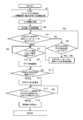
- the start-up process step means a step until an electrolytic reaction can be started in the electrolytic cell stack device and power generation can be started in the fuel cell stack device 3 until a rated operation can be performed.
- raw fuel such as city gas or propane gas is supplied to a manifold (shown as an SOFC manifold in FIG. 8) of the fuel cell stack device through a fuel supply pipe in step S ⁇ b> 1.
- a manifold shown as an SOFC manifold in FIG. 8
- an oxygen-containing gas is supplied to the outer electrode layer of the fuel cell stack apparatus.
- a blower etc. can be used, for example.
- step S2 the ignition device is started to burn the raw fuel discharged from the flow holes 26 of the fuel cells 10.
- the ignition device should just be arrange
- step S3 the water pump is operated to start supplying water to the vaporizer.
- the temperature of the fuel cell stack device is not sufficiently increased, and water may not be vaporized. Therefore, for example, a valve may be provided in the vaporizer or the water vapor inflow pipe, a temperature sensor may be provided in the vaporizer, and the valve may be controlled to open after the temperature measured by the temperature sensor reaches the temperature at which water is vaporized. .
- the water vapor When water is supplied to the vaporizer to generate water vapor, the water vapor is supplied to the first manifold of the electrolytic cell stack through the water vapor inflow pipe.
- the water vapor supplied to the first manifold flows upward through the flow hole of the electrolysis cell.
- the water vapor flowing through the flow holes of the electrolysis cell flows to the second manifold in the state of water vapor.
- the water vapor flowing through the second manifold is supplied to the manifold of the fuel cell stack device through the gas introduction pipe.
- the valve is controlled so that water vapor is not released to the outside through the gas flow pipe.
- step S4 the process proceeds to step S4 to detect whether or not water vapor is supplied from the electrolytic cell stack device to the manifold of the fuel cell stack device. In other words, it is detected whether water is vaporized in the vaporizer.
- a detection method for example, a sensor such as a humidity sensor can be disposed in the gas introduction pipe to check whether water vapor is flowing.
- step S5 the temperature of the fuel cell stack device is set to a first predetermined value. Detect whether the temperature is lower than the set temperature. That is, while the raw fuel is continuously supplied to the manifold of the fuel cell stack apparatus and the situation where the water vapor is not supplied to the manifold of the fuel cell stack apparatus is continued, It is detected whether or not the first set temperature has been reached. Incidentally, by providing a temperature sensor in the vicinity of the fuel cell stack device, the temperature of the fuel cell stack device can be measured.
- step S4 If the temperature of the fuel cell stack device is lower than the first set temperature, the carbon contained in the raw fuel is less likely to deposit, so the process returns to step S4 and water vapor is removed from the electrolytic cell stack device. It is detected whether it was supplied to the manifold of the device.
- step S6 water or oxygen-containing gas is directly subsidized to the manifold of the fuel cell stack device to prevent carbon deposition. It supplies using an apparatus (oxygen-containing gas supply apparatus and water vapor supply apparatus).
- the oxygen-containing gas may be supplied in combination with a blower that supplies the oxygen-containing gas to the outer electrode layer of the fuel cell.
- the first set temperature may be lower than the temperature at which carbon deposition generated by decomposition of the raw fuel is started, and may be appropriately set in accordance with the type of the raw fuel within a range of 200 to 350 ° C., for example. it can.
- step S4 When it is determined in step S4 that water vapor has been supplied from the electrolytic cell stack device to the manifold of the fuel cell stack device, or in step S6, water vapor or oxygen-containing gas is directly supplied to the manifold of the fuel cell stack device. After that, the process proceeds to step S7, and it is confirmed whether or not the temperature of the fuel cell stack device is equal to or higher than a second set temperature (power generation start possible temperature) higher than the first set temperature.
- a second set temperature power generation start possible temperature
- step S7 after the temperature of the fuel cell stack device becomes equal to or higher than the second set temperature (temperature at which power generation can be started), power generation of the fuel cell stack device is started.
- the fuel battery cell is a fuel battery cell containing Ni or the like
- the raw fuel can be reformed (so-called internal reforming).
- the reforming catalyst may be disposed in the manifold of the fuel cell stack device.
- a reformer for reforming raw fuel is provided, a sufficient reforming reaction can be performed at this temperature.
- the electrolysis cell stack apparatus 2 is generated by heat generated by power generation or combustion heat generated by burning a gas containing hydrogen not used for power generation above the fuel battery cell. Temperature rises.
- step S9 the temperature of the electrolysis cell stack apparatus is appropriately set at a predetermined temperature (250 to 350 ° C. within the range of 250 to 350 ° C.), which is the lower limit of the steam oxidation temperature of Ni, which is the main component of the electroconductive cell support and cathode. It is detected whether or not it can be set.
- the temperature of an electrolysis cell stack apparatus can be measured by arrange
- step S9 If it is determined that the temperature of the electrolysis cell stack apparatus is lower than the predetermined temperature, the process returns to step S9 again to repeat the measurement of the temperature of the electrolysis cell stack apparatus.
- step S10 a current is passed through the electrolysis cell stack apparatus via the end conductive member.
- This current may be supplied from a so-called system power supply, or a part of the electric power generated by the power generation of the fuel cell stack device may be supplied to the electrolysis cell stack device.
- an electric current is passed through the electrolytic cell stack device, an electrolytic reaction occurs in the electrolytic cell, and a gas containing hydrogen is generated.
- step S11 it is detected whether or not the amount of the gas containing hydrogen supplied from the electrolysis cell stack apparatus is supplied to the manifold of the fuel cell stack apparatus by a predetermined amount or more.
- a gas containing a predetermined amount or more of hydrogen is supplied to the manifold of the fuel cell stack device, it is not necessary to continue to supply the raw fuel via the fuel supply pipe. Stop supplying.
- two pressure sensors are connected to the gas introduction pipe.
- the amount of gas containing hydrogen can be detected based on the difference in pressure measured by the pressure sensor, and the hydrogen concentration can be detected by providing a hydrogen sensor in addition to this. Based on the information on the gas amount and the hydrogen concentration, it is possible to detect whether or not the amount of the gas containing hydrogen supplied from the electrolysis cell stack apparatus is equal to or greater than a predetermined amount.
- the predetermined amount can be set as appropriate according to the number of fuel cells constituting the fuel cell stack device, but is preferably equal to or higher than the minimum flow rate capable of generating power in the fuel cells. . In the case where a reformer is provided, it may be set as appropriate in consideration of the amount of gas containing hydrogen produced in the reformer.
- control device may start normal operation (rated operation) control. That is, the operation of each device may be appropriately controlled based on the temperature of the electrolytic cell stack device or the fuel cell stack device, the external load, the amount of hydrogen-containing gas required to be discharged from the gas distribution pipe, and the like.
- the supply of current to the external load or the electrolytic cell stack device is stopped in order to stop the power generation of the fuel cell stack device.
- Joule heat in the fuel cell stack device is reduced, and the temperature of the fuel cell stack device is lowered.
- the amount of raw fuel and hydrogen-containing gas supplied to the fuel cell stack apparatus or the amount of raw fuel supplied to the reformer may be reduced. Thereby, the temperature of the fuel cell stack device can be lowered more quickly.
- the amount of current supplied to the electrolysis cell stack apparatus is decreased in order to reduce the electrolytic reaction in the electrolysis cell stack apparatus.
- a predetermined temperature first set temperature
- carbon contained in the raw fuel is deposited. Therefore, in order to suppress deterioration of the fuel cell, when the temperature of the fuel cell stack apparatus is equal to or higher than a predetermined temperature, it is preferable to supply a gas containing water vapor from the electrolytic cell stack apparatus.
- a gas with a small amount of water vapor is supplied to the fuel cell stack apparatus. Therefore, for example, a gas with a large amount of water vapor can be supplied to the fuel cell stack device by reducing the amount of current flowing through the electrolysis cell stack device and suppressing the electrolytic reaction.
- the amount of water supplied to the vaporizer can be reduced according to the amount of water vapor supplied to the fuel cell stack device.
- the supply of the raw fuel and oxygen-containing gas supplied to the fuel cell stack device is stopped and electrolysis is performed. Stop energization of the cell stack device and stop water supplied to the vaporizer.
- control device When the control device performs the above-described control, deterioration of the fuel cell can be suppressed, and a hybrid system with improved reliability can be obtained.
- a vertical stripe type cell is used as the electrolytic cell or the fuel cell, but the inner electrode layer 22, the solid electrolyte layer 23, and the outer electrode layer 24 are sequentially arranged on the support.
- a so-called horizontal-striped cell having a plurality of electrolytic element portions and power generation element portions can also be used.
- Electrolytic cell stack device 2 Electrolytic cell stack device 3: Fuel cell stack device 4: Electrolytic cell 5: Electrolytic cell stack 6: First manifold 7, 31: Second manifold 10: Fuel cell 11 : Fuel cell stack 12: Manifold 15: Water supply pipe 16: Vaporizer 17: Water vapor inflow pipe 18: Gas outlet pipe 19: Gas introduction pipe 20: Fuel supply pipe 21: Conductive support 22: Inner electrode layer 23: Solid electrolyte layer 24: Outer electrode layer 26: Flow hole 32: Space 33: Partition member 34: Supply part 35: Recovery part 36: Outward flow hole 37: Return flow hole 39: Reformer 40: Raw fuel supply pipe
Abstract
Description
カソード:H2O+2e- → H2+O2-
アノード:O2 - → 1/2O2+2e-
カソード:1/2O2+2e- →O2 -
アノード:H2+O2- →H2O+2e-
2:電解セルスタック装置
3:燃料電池セルスタック装置
4:電解セル
5:電解セルスタック
6:第1のマニホールド
7、31:第2のマニホールド
10:燃料電池セル
11:燃料電池セルスタック
12:マニホールド
15:水供給管
16:気化器
17:水蒸気流入管
18:ガス導出管
19:ガス導入管
20:燃料供給管
21:導電性支持体
22:内側電極層
23:固体電解質層
24:外側電極層
26:流通孔
32:空間
33:仕切部材
34:供給部
35:回収部
36:往路側流通孔
37:復路側流通孔
39:改質器
40:原燃料供給管
Claims (13)
- 水蒸気を含むガスより水素を含むガスを生成する電解セルを複数個備える電解セルスタックを有する電解セルスタック装置と、
燃料電池セルを複数個備える燃料電池セルスタックを有する燃料電池セルスタック装置とを備え、
前記電解セルスタック装置にて生成された水素を含むガスの少なくとも一部が前記燃料電池セルスタック装置に供給されるように構成されており、
前記電解セルスタック装置に供給する水蒸気を含むガスを生成するための気化器が前記燃料電池セルスタックの近傍に配置されている、
ことを特徴とするハイブリッド装置。 - 前記気化器が、前記燃料電池セルスタックのうち、前記燃料電池セルの配列方向に沿った中央部に配置されていることを特徴とする請求項1に記載のハイブリッド装置。
- 前記燃料電池セルスタック装置で発電された電流の少なくとも一部が、前記電解セルスタック装置に供給されることを特徴とする請求項1または請求項2に記載のハイブリッド装置。
- 前記気化器が、前記燃料電池セルスタックのうち、前記燃料電池セルの配列方向に沿った側方に配置されていることを特徴とする請求項1乃至請求項3のうちいずれかに記載のハイブリッド装置。
- 前記燃料電池セルが、内部に一端から他端に貫通するガス流路を備えており、発電で利用されなかった余剰の水素を含むガスを、前記燃料電池セルの他端側で燃焼させる構成とされており、前記気化器が、前記燃料電池セルの他端側に配置されていることを特徴とする請求項1乃至請求項3のうちいずれかに記載のハイブリッド装置。
- 前記電解セルが、内部に一端から他端に貫通するガス流路を備えており、前記電解セルスタック装置が、複数個の前記電解セルの一端を固定するとともに、該電解セルに水蒸気を含むガスを供給するための第1のマニホールドと、複数個の前記電解セルの他端を固定するとともに、該電解セルにより生成された水素を含むガスを回収するための第2のマニホールドと、を備えることを特徴とする請求項1乃至請求項5のうちいずれかに記載のハイブリッド装置。
- 前記電解セルが、内部に一端から他端に貫通する二つ以上のガス流路を備えており、前記電解セルスタック装置が、複数個の前記電解セルの一端を固定する第1のマニホールドと、複数個の前記電解セルの他端を固定する第2のマニホールドと、を備え、前記第1のマニホールドは、水蒸気を含むガスが供給される供給部と、水素を含むガスを回収する回収部とを含み、前記供給部に供給された水素を含むガスの少なくとも一部が、前記二つ以上のガス流路の一方を通って前記第2のマニホールドに流れ、前記二つ以上のガス流路の他方を通って前記回収部に流れるように構成されていることを特徴とする請求項1乃至請求項5のうちいずれかに記載のハイブリッド装置。
- 前記燃料電池セルが、内部に一端から他端に貫通するガス流路を備えており、発電で利用されなかった余剰の水素を含有するガスを、前記燃料電池セルの他端側で燃焼させる構成とされており、前記燃料電池セルの他端側近傍に、原燃料を改質して前記燃料電池セルに供給する水素を含有するガスを生成する改質器が配置されていることを特徴とする請求項1乃至請求項7のうちいずれかに記載のハイブリッド装置。
- 前記燃料電池セルスタック装置が、前記燃料電池セルの一端を固定するマニホールドと、該マニホールドに接続された、原燃料または水素を含むガスを供給するための燃料供給管とをさらに含むことを特徴とする請求項1乃至請求項8に記載のハイブリッド装置。
- 請求項8または請求項9に記載のハイブリッド装置と、前記燃料電池セルスタック装置の前記マニホールドに酸素を含むガスまたは水蒸気を供給するための補助装置とを備えることを特徴とするハイブリッドシステム。
- 前記燃料電池セルスタック装置の温度を測定するための温度センサと、制御装置とを備え、該制御装置は、起動処理工程において、前記燃料電池セルスタック装置の前記マニホールドに原燃料が供給されており、前記電解セルスタック装置より前記燃料電池セルスタック装置の前記マニホールドに水蒸気が供給されていない状態で、前記温度センサの温度が第1の設定温度となった場合に、前記補助装置を作動させるように制御することを特徴とする請求項10に記載のハイブリッドシステム。
- 前記改質器または前記燃料電池セルスタック装置の前記マニホールドに、原燃料または水素を含むガスを外部より供給するための燃料供給装置をさらに備え、前記制御装置は、前記電解セルスタック装置より前記燃料電池セルスタック装置の前記マニホールドに供給される水素を含むガスの量が所定量以上供給された場合に、前記燃料供給装置の稼働を停止するように制御することを特徴とする請求項11に記載のハイブリッドシステム。
- 請求項8または請求項9に記載のハイブリッド装置と、
該ハイブリッド装置の稼働停止処理において、前記燃料電池セルスタック装置の外部負荷への電流の供給を停止するとともに、前記燃料電池セルの温度が所定の温度以下となったのちに、前記電解セルスタック装置への電流の供給および前記気化器への水の供給を停止するように制御する制御装置とを備えることを特徴とするハイブリッドシステム。
Priority Applications (4)
| Application Number | Priority Date | Filing Date | Title |
|---|---|---|---|
| EP14830322.5A EP3026745B1 (en) | 2013-07-24 | 2014-07-24 | Hybrid device and hybrid system |
| CN201480040753.3A CN105393392B (zh) | 2013-07-24 | 2014-07-24 | 混合动力装置以及混合动力系统 |
| US14/906,489 US20160164128A1 (en) | 2013-07-24 | 2014-07-24 | Hybrid device and hybrid system |
| JP2015528344A JP6219953B2 (ja) | 2013-07-24 | 2014-07-24 | ハイブリッド装置およびハイブリッドシステム |
Applications Claiming Priority (2)
| Application Number | Priority Date | Filing Date | Title |
|---|---|---|---|
| JP2013153688 | 2013-07-24 | ||
| JP2013-153688 | 2013-07-24 |
Publications (1)
| Publication Number | Publication Date |
|---|---|
| WO2015012372A1 true WO2015012372A1 (ja) | 2015-01-29 |
Family
ID=52393405
Family Applications (1)
| Application Number | Title | Priority Date | Filing Date |
|---|---|---|---|
| PCT/JP2014/069613 WO2015012372A1 (ja) | 2013-07-24 | 2014-07-24 | ハイブリッド装置およびハイブリッドシステム |
Country Status (5)
| Country | Link |
|---|---|
| US (1) | US20160164128A1 (ja) |
| EP (1) | EP3026745B1 (ja) |
| JP (1) | JP6219953B2 (ja) |
| CN (1) | CN105393392B (ja) |
| WO (1) | WO2015012372A1 (ja) |
Cited By (6)
| Publication number | Priority date | Publication date | Assignee | Title |
|---|---|---|---|---|
| JP6275225B1 (ja) * | 2016-11-02 | 2018-02-07 | 日本碍子株式会社 | 燃料電池スタック |
| JPWO2017154137A1 (ja) * | 2016-03-09 | 2019-02-14 | 株式会社東芝 | 固体酸化物形電解セルスタックの収容容器、水素製造システム、電力貯蔵システム |
| JP2019129018A (ja) * | 2018-01-23 | 2019-08-01 | Toto株式会社 | 燃料電池セルスタック装置 |
| WO2020012699A1 (ja) * | 2018-07-12 | 2020-01-16 | 日本碍子株式会社 | セルスタック装置 |
| WO2020049760A1 (ja) * | 2018-09-07 | 2020-03-12 | 日本碍子株式会社 | マニホールド、セルスタック装置、及び電気化学セル |
| US10727524B2 (en) | 2018-07-12 | 2020-07-28 | Ngk Insulators, Ltd. | Cell stack device |
Families Citing this family (3)
| Publication number | Priority date | Publication date | Assignee | Title |
|---|---|---|---|---|
| JP6030261B1 (ja) * | 2015-07-03 | 2016-11-24 | 日本碍子株式会社 | 燃料電池スタック |
| JP6605101B1 (ja) * | 2018-09-07 | 2019-11-13 | 日本碍子株式会社 | マニホールド、及びセルスタック装置 |
| GB2604593B (en) * | 2021-03-03 | 2024-01-24 | Ceres Ip Co Ltd | Fuel cell system |
Citations (8)
| Publication number | Priority date | Publication date | Assignee | Title |
|---|---|---|---|---|
| JPH06163064A (ja) * | 1992-11-18 | 1994-06-10 | Kansai Electric Power Co Inc:The | 電力貯蔵装置 |
| JPH11214021A (ja) | 1998-01-27 | 1999-08-06 | Ishikawajima Harima Heavy Ind Co Ltd | 固体電解質型燃料電池発電設備 |
| JP2005093222A (ja) * | 2003-09-17 | 2005-04-07 | Osaka Gas Co Ltd | 燃料電池システム |
| JP2009070585A (ja) * | 2007-09-10 | 2009-04-02 | Nippon Oil Corp | 水蒸気発生器及び燃料電池システムの運転方法 |
| JP2010287502A (ja) * | 2009-06-12 | 2010-12-24 | Ngk Spark Plug Co Ltd | 燃料電池用原料供給装置 |
| JP2011249161A (ja) * | 2010-05-27 | 2011-12-08 | Aquafairy Kk | 発電装置 |
| JP2012094417A (ja) * | 2010-10-28 | 2012-05-17 | Kyocera Corp | 燃料電池用気化器、燃料電池用改質器、セルスタック装置、燃料電池モジュール、燃料電池装置および充填物収納ケース |
| JP2013030359A (ja) * | 2011-07-28 | 2013-02-07 | Kyocera Corp | 燃料電池装置 |
Family Cites Families (4)
| Publication number | Priority date | Publication date | Assignee | Title |
|---|---|---|---|---|
| US7276306B2 (en) * | 2003-03-12 | 2007-10-02 | The Regents Of The University Of California | System for the co-production of electricity and hydrogen |
| US8003268B2 (en) * | 2005-03-31 | 2011-08-23 | Smith William F | Modular regenerative fuel cell system |
| JP2006331678A (ja) * | 2005-05-23 | 2006-12-07 | Honda Motor Co Ltd | 燃料電池システム |
| JP2009224293A (ja) * | 2008-03-19 | 2009-10-01 | Toyota Motor Corp | 燃料電池システム |
-
2014
- 2014-07-24 JP JP2015528344A patent/JP6219953B2/ja active Active
- 2014-07-24 CN CN201480040753.3A patent/CN105393392B/zh active Active
- 2014-07-24 WO PCT/JP2014/069613 patent/WO2015012372A1/ja active Application Filing
- 2014-07-24 EP EP14830322.5A patent/EP3026745B1/en active Active
- 2014-07-24 US US14/906,489 patent/US20160164128A1/en not_active Abandoned
Patent Citations (8)
| Publication number | Priority date | Publication date | Assignee | Title |
|---|---|---|---|---|
| JPH06163064A (ja) * | 1992-11-18 | 1994-06-10 | Kansai Electric Power Co Inc:The | 電力貯蔵装置 |
| JPH11214021A (ja) | 1998-01-27 | 1999-08-06 | Ishikawajima Harima Heavy Ind Co Ltd | 固体電解質型燃料電池発電設備 |
| JP2005093222A (ja) * | 2003-09-17 | 2005-04-07 | Osaka Gas Co Ltd | 燃料電池システム |
| JP2009070585A (ja) * | 2007-09-10 | 2009-04-02 | Nippon Oil Corp | 水蒸気発生器及び燃料電池システムの運転方法 |
| JP2010287502A (ja) * | 2009-06-12 | 2010-12-24 | Ngk Spark Plug Co Ltd | 燃料電池用原料供給装置 |
| JP2011249161A (ja) * | 2010-05-27 | 2011-12-08 | Aquafairy Kk | 発電装置 |
| JP2012094417A (ja) * | 2010-10-28 | 2012-05-17 | Kyocera Corp | 燃料電池用気化器、燃料電池用改質器、セルスタック装置、燃料電池モジュール、燃料電池装置および充填物収納ケース |
| JP2013030359A (ja) * | 2011-07-28 | 2013-02-07 | Kyocera Corp | 燃料電池装置 |
Cited By (9)
| Publication number | Priority date | Publication date | Assignee | Title |
|---|---|---|---|---|
| JPWO2017154137A1 (ja) * | 2016-03-09 | 2019-02-14 | 株式会社東芝 | 固体酸化物形電解セルスタックの収容容器、水素製造システム、電力貯蔵システム |
| JP6275225B1 (ja) * | 2016-11-02 | 2018-02-07 | 日本碍子株式会社 | 燃料電池スタック |
| JP2019129018A (ja) * | 2018-01-23 | 2019-08-01 | Toto株式会社 | 燃料電池セルスタック装置 |
| JP7002951B2 (ja) | 2018-01-23 | 2022-02-04 | 森村Sofcテクノロジー株式会社 | 燃料電池セルスタック装置 |
| WO2020012699A1 (ja) * | 2018-07-12 | 2020-01-16 | 日本碍子株式会社 | セルスタック装置 |
| US10727524B2 (en) | 2018-07-12 | 2020-07-28 | Ngk Insulators, Ltd. | Cell stack device |
| WO2020049760A1 (ja) * | 2018-09-07 | 2020-03-12 | 日本碍子株式会社 | マニホールド、セルスタック装置、及び電気化学セル |
| JP2020043048A (ja) * | 2018-09-07 | 2020-03-19 | 日本碍子株式会社 | マニホールド、セルスタック装置、及び電気化学セル |
| US11799119B2 (en) | 2018-09-07 | 2023-10-24 | Ngk Insulators, Ltd. | Manifold, cell stack device, and electrochemical cell |
Also Published As
| Publication number | Publication date |
|---|---|
| EP3026745A4 (en) | 2016-12-21 |
| JPWO2015012372A1 (ja) | 2017-03-02 |
| JP6219953B2 (ja) | 2017-10-25 |
| US20160164128A1 (en) | 2016-06-09 |
| EP3026745B1 (en) | 2018-07-04 |
| CN105393392A (zh) | 2016-03-09 |
| CN105393392B (zh) | 2018-04-10 |
| EP3026745A1 (en) | 2016-06-01 |
Similar Documents
| Publication | Publication Date | Title |
|---|---|---|
| JP6219953B2 (ja) | ハイブリッド装置およびハイブリッドシステム | |
| JP6463203B2 (ja) | 電気化学素子、それを備えた電気化学モジュール、電気化学装置およびエネルギーシステム | |
| US10396377B2 (en) | Fuel cell device | |
| JP6105423B2 (ja) | 電解セルスタック装置及び電解装置 | |
| JP7174498B2 (ja) | 電気化学素子ユニット、電気化学モジュール、電気化学装置、エネルギーシステム、固体酸化物形燃料電池ユニットおよび固体酸化物形電解セルユニット | |
| CN111868983A (zh) | 燃料电池单电池单元、燃料电池模块及燃料电池装置 | |
| WO2014208448A1 (ja) | セルユニット、セルスタック装置、セルユニット装置およびモジュール | |
| JP5377271B2 (ja) | セルスタック装置、燃料電池モジュールおよび燃料電池装置 | |
| JP2013030359A (ja) | 燃料電池装置 | |
| JP5440751B2 (ja) | 燃料電池システム | |
| JP5437152B2 (ja) | 横縞型固体酸化物形燃料電池セルスタックおよび燃料電池 | |
| JP5388818B2 (ja) | 燃料電池モジュールおよび燃料電池装置 | |
| JP6277808B2 (ja) | 固体酸化物形燃料電池スタック、固体酸化物形燃料電池モジュールおよび固体酸化物形燃料電池システム | |
| JP6369081B2 (ja) | 固体酸化物形燃料電池スタック、固体酸化物形燃料電池モジュールおよび固体酸化物形燃料電池システム | |
| JP5977142B2 (ja) | 燃料電池装置 | |
| JP6394191B2 (ja) | 固体酸化物形燃料電池スタック、固体酸化物形燃料電池モジュールおよび固体酸化物形燃料電池システム | |
| JP6121826B2 (ja) | 電解装置 | |
| JP6711558B2 (ja) | Sofcセルチューブ及び固体酸化物形燃料電池装置 | |
| JP6140603B2 (ja) | 燃料電池装置 | |
| JP6110247B2 (ja) | 電解セルスタック装置および電解装置 | |
| JP5299207B2 (ja) | 燃料電池システムおよび燃料電池システムの運転方法 | |
| JP6059038B2 (ja) | セルスタック装置、燃料電池モジュールおよび燃料電池装置 | |
| JP2017130273A (ja) | 固体酸化物形燃料電池スタック、固体酸化物形燃料電池モジュールおよび固体酸化物形燃料電池システム | |
| JP2017033628A (ja) | 固体酸化物形燃料電池スタック、固体酸化物形燃料電池モジュールおよび固体酸化物形燃料電池システム | |
| JP2015185298A (ja) | 固体酸化物形燃料電池スタック、固体酸化物形燃料電池モジュールおよび固体酸化物形燃料電池システム |
Legal Events
| Date | Code | Title | Description |
|---|---|---|---|
| WWE | Wipo information: entry into national phase |
Ref document number: 201480040753.3 Country of ref document: CN |
|
| 121 | Ep: the epo has been informed by wipo that ep was designated in this application |
Ref document number: 14830322 Country of ref document: EP Kind code of ref document: A1 |
|
| ENP | Entry into the national phase |
Ref document number: 2015528344 Country of ref document: JP Kind code of ref document: A |
|
| WWE | Wipo information: entry into national phase |
Ref document number: 14906489 Country of ref document: US Ref document number: 2014830322 Country of ref document: EP |
|
| NENP | Non-entry into the national phase |
Ref country code: DE |