WO2015011997A1 - Système de guidage à prévision d'énergie restante - Google Patents
Système de guidage à prévision d'énergie restante Download PDFInfo
- Publication number
- WO2015011997A1 WO2015011997A1 PCT/JP2014/064858 JP2014064858W WO2015011997A1 WO 2015011997 A1 WO2015011997 A1 WO 2015011997A1 JP 2014064858 W JP2014064858 W JP 2014064858W WO 2015011997 A1 WO2015011997 A1 WO 2015011997A1
- Authority
- WO
- WIPO (PCT)
- Prior art keywords
- predicted
- information
- vehicle
- passing point
- energy
- Prior art date
Links
- 238000000605 extraction Methods 0.000 claims abstract description 20
- 239000000284 extract Substances 0.000 claims abstract description 18
- 238000000034 method Methods 0.000 claims description 45
- 238000001514 detection method Methods 0.000 claims description 5
- 230000006870 function Effects 0.000 description 57
- 238000004891 communication Methods 0.000 description 22
- 238000010586 diagram Methods 0.000 description 8
- 238000012545 processing Methods 0.000 description 6
- 230000006866 deterioration Effects 0.000 description 4
- OKKJLVBELUTLKV-UHFFFAOYSA-N Methanol Chemical compound OC OKKJLVBELUTLKV-UHFFFAOYSA-N 0.000 description 3
- 239000000446 fuel Substances 0.000 description 3
- UFHFLCQGNIYNRP-UHFFFAOYSA-N Hydrogen Chemical compound [H][H] UFHFLCQGNIYNRP-UHFFFAOYSA-N 0.000 description 2
- 238000013461 design Methods 0.000 description 1
- 239000007789 gas Substances 0.000 description 1
- 239000001257 hydrogen Substances 0.000 description 1
- 229910052739 hydrogen Inorganic materials 0.000 description 1
- 238000010348 incorporation Methods 0.000 description 1
Images


Classifications
-
- B—PERFORMING OPERATIONS; TRANSPORTING
- B60—VEHICLES IN GENERAL
- B60L—PROPULSION OF ELECTRICALLY-PROPELLED VEHICLES; SUPPLYING ELECTRIC POWER FOR AUXILIARY EQUIPMENT OF ELECTRICALLY-PROPELLED VEHICLES; ELECTRODYNAMIC BRAKE SYSTEMS FOR VEHICLES IN GENERAL; MAGNETIC SUSPENSION OR LEVITATION FOR VEHICLES; MONITORING OPERATING VARIABLES OF ELECTRICALLY-PROPELLED VEHICLES; ELECTRIC SAFETY DEVICES FOR ELECTRICALLY-PROPELLED VEHICLES
- B60L53/00—Methods of charging batteries, specially adapted for electric vehicles; Charging stations or on-board charging equipment therefor; Exchange of energy storage elements in electric vehicles
- B60L53/60—Monitoring or controlling charging stations
- B60L53/65—Monitoring or controlling charging stations involving identification of vehicles or their battery types
-
- B—PERFORMING OPERATIONS; TRANSPORTING
- B60—VEHICLES IN GENERAL
- B60L—PROPULSION OF ELECTRICALLY-PROPELLED VEHICLES; SUPPLYING ELECTRIC POWER FOR AUXILIARY EQUIPMENT OF ELECTRICALLY-PROPELLED VEHICLES; ELECTRODYNAMIC BRAKE SYSTEMS FOR VEHICLES IN GENERAL; MAGNETIC SUSPENSION OR LEVITATION FOR VEHICLES; MONITORING OPERATING VARIABLES OF ELECTRICALLY-PROPELLED VEHICLES; ELECTRIC SAFETY DEVICES FOR ELECTRICALLY-PROPELLED VEHICLES
- B60L58/00—Methods or circuit arrangements for monitoring or controlling batteries or fuel cells, specially adapted for electric vehicles
- B60L58/10—Methods or circuit arrangements for monitoring or controlling batteries or fuel cells, specially adapted for electric vehicles for monitoring or controlling batteries
- B60L58/12—Methods or circuit arrangements for monitoring or controlling batteries or fuel cells, specially adapted for electric vehicles for monitoring or controlling batteries responding to state of charge [SoC]
-
- G—PHYSICS
- G01—MEASURING; TESTING
- G01C—MEASURING DISTANCES, LEVELS OR BEARINGS; SURVEYING; NAVIGATION; GYROSCOPIC INSTRUMENTS; PHOTOGRAMMETRY OR VIDEOGRAMMETRY
- G01C21/00—Navigation; Navigational instruments not provided for in groups G01C1/00 - G01C19/00
- G01C21/26—Navigation; Navigational instruments not provided for in groups G01C1/00 - G01C19/00 specially adapted for navigation in a road network
- G01C21/34—Route searching; Route guidance
- G01C21/3453—Special cost functions, i.e. other than distance or default speed limit of road segments
- G01C21/3469—Fuel consumption; Energy use; Emission aspects
-
- G—PHYSICS
- G01—MEASURING; TESTING
- G01C—MEASURING DISTANCES, LEVELS OR BEARINGS; SURVEYING; NAVIGATION; GYROSCOPIC INSTRUMENTS; PHOTOGRAMMETRY OR VIDEOGRAMMETRY
- G01C21/00—Navigation; Navigational instruments not provided for in groups G01C1/00 - G01C19/00
- G01C21/26—Navigation; Navigational instruments not provided for in groups G01C1/00 - G01C19/00 specially adapted for navigation in a road network
- G01C21/34—Route searching; Route guidance
- G01C21/36—Input/output arrangements for on-board computers
- G01C21/3697—Output of additional, non-guidance related information, e.g. low fuel level
-
- G—PHYSICS
- G06—COMPUTING; CALCULATING OR COUNTING
- G06Q—INFORMATION AND COMMUNICATION TECHNOLOGY [ICT] SPECIALLY ADAPTED FOR ADMINISTRATIVE, COMMERCIAL, FINANCIAL, MANAGERIAL OR SUPERVISORY PURPOSES; SYSTEMS OR METHODS SPECIALLY ADAPTED FOR ADMINISTRATIVE, COMMERCIAL, FINANCIAL, MANAGERIAL OR SUPERVISORY PURPOSES, NOT OTHERWISE PROVIDED FOR
- G06Q30/00—Commerce
- G06Q30/06—Buying, selling or leasing transactions
- G06Q30/0601—Electronic shopping [e-shopping]
- G06Q30/0639—Item locations
-
- G06Q50/40—
-
- G—PHYSICS
- G09—EDUCATION; CRYPTOGRAPHY; DISPLAY; ADVERTISING; SEALS
- G09B—EDUCATIONAL OR DEMONSTRATION APPLIANCES; APPLIANCES FOR TEACHING, OR COMMUNICATING WITH, THE BLIND, DEAF OR MUTE; MODELS; PLANETARIA; GLOBES; MAPS; DIAGRAMS
- G09B29/00—Maps; Plans; Charts; Diagrams, e.g. route diagram
- G09B29/003—Maps
-
- G—PHYSICS
- G09—EDUCATION; CRYPTOGRAPHY; DISPLAY; ADVERTISING; SEALS
- G09B—EDUCATIONAL OR DEMONSTRATION APPLIANCES; APPLIANCES FOR TEACHING, OR COMMUNICATING WITH, THE BLIND, DEAF OR MUTE; MODELS; PLANETARIA; GLOBES; MAPS; DIAGRAMS
- G09B29/00—Maps; Plans; Charts; Diagrams, e.g. route diagram
- G09B29/10—Map spot or coordinate position indicators; Map reading aids
-
- B—PERFORMING OPERATIONS; TRANSPORTING
- B60—VEHICLES IN GENERAL
- B60L—PROPULSION OF ELECTRICALLY-PROPELLED VEHICLES; SUPPLYING ELECTRIC POWER FOR AUXILIARY EQUIPMENT OF ELECTRICALLY-PROPELLED VEHICLES; ELECTRODYNAMIC BRAKE SYSTEMS FOR VEHICLES IN GENERAL; MAGNETIC SUSPENSION OR LEVITATION FOR VEHICLES; MONITORING OPERATING VARIABLES OF ELECTRICALLY-PROPELLED VEHICLES; ELECTRIC SAFETY DEVICES FOR ELECTRICALLY-PROPELLED VEHICLES
- B60L2240/00—Control parameters of input or output; Target parameters
- B60L2240/10—Vehicle control parameters
- B60L2240/12—Speed
-
- B—PERFORMING OPERATIONS; TRANSPORTING
- B60—VEHICLES IN GENERAL
- B60L—PROPULSION OF ELECTRICALLY-PROPELLED VEHICLES; SUPPLYING ELECTRIC POWER FOR AUXILIARY EQUIPMENT OF ELECTRICALLY-PROPELLED VEHICLES; ELECTRODYNAMIC BRAKE SYSTEMS FOR VEHICLES IN GENERAL; MAGNETIC SUSPENSION OR LEVITATION FOR VEHICLES; MONITORING OPERATING VARIABLES OF ELECTRICALLY-PROPELLED VEHICLES; ELECTRIC SAFETY DEVICES FOR ELECTRICALLY-PROPELLED VEHICLES
- B60L2240/00—Control parameters of input or output; Target parameters
- B60L2240/10—Vehicle control parameters
- B60L2240/26—Vehicle weight
-
- B—PERFORMING OPERATIONS; TRANSPORTING
- B60—VEHICLES IN GENERAL
- B60L—PROPULSION OF ELECTRICALLY-PROPELLED VEHICLES; SUPPLYING ELECTRIC POWER FOR AUXILIARY EQUIPMENT OF ELECTRICALLY-PROPELLED VEHICLES; ELECTRODYNAMIC BRAKE SYSTEMS FOR VEHICLES IN GENERAL; MAGNETIC SUSPENSION OR LEVITATION FOR VEHICLES; MONITORING OPERATING VARIABLES OF ELECTRICALLY-PROPELLED VEHICLES; ELECTRIC SAFETY DEVICES FOR ELECTRICALLY-PROPELLED VEHICLES
- B60L2240/00—Control parameters of input or output; Target parameters
- B60L2240/60—Navigation input
- B60L2240/62—Vehicle position
- B60L2240/622—Vehicle position by satellite navigation
-
- B—PERFORMING OPERATIONS; TRANSPORTING
- B60—VEHICLES IN GENERAL
- B60L—PROPULSION OF ELECTRICALLY-PROPELLED VEHICLES; SUPPLYING ELECTRIC POWER FOR AUXILIARY EQUIPMENT OF ELECTRICALLY-PROPELLED VEHICLES; ELECTRODYNAMIC BRAKE SYSTEMS FOR VEHICLES IN GENERAL; MAGNETIC SUSPENSION OR LEVITATION FOR VEHICLES; MONITORING OPERATING VARIABLES OF ELECTRICALLY-PROPELLED VEHICLES; ELECTRIC SAFETY DEVICES FOR ELECTRICALLY-PROPELLED VEHICLES
- B60L2240/00—Control parameters of input or output; Target parameters
- B60L2240/60—Navigation input
- B60L2240/68—Traffic data
-
- B—PERFORMING OPERATIONS; TRANSPORTING
- B60—VEHICLES IN GENERAL
- B60L—PROPULSION OF ELECTRICALLY-PROPELLED VEHICLES; SUPPLYING ELECTRIC POWER FOR AUXILIARY EQUIPMENT OF ELECTRICALLY-PROPELLED VEHICLES; ELECTRODYNAMIC BRAKE SYSTEMS FOR VEHICLES IN GENERAL; MAGNETIC SUSPENSION OR LEVITATION FOR VEHICLES; MONITORING OPERATING VARIABLES OF ELECTRICALLY-PROPELLED VEHICLES; ELECTRIC SAFETY DEVICES FOR ELECTRICALLY-PROPELLED VEHICLES
- B60L2240/00—Control parameters of input or output; Target parameters
- B60L2240/70—Interactions with external data bases, e.g. traffic centres
-
- B—PERFORMING OPERATIONS; TRANSPORTING
- B60—VEHICLES IN GENERAL
- B60L—PROPULSION OF ELECTRICALLY-PROPELLED VEHICLES; SUPPLYING ELECTRIC POWER FOR AUXILIARY EQUIPMENT OF ELECTRICALLY-PROPELLED VEHICLES; ELECTRODYNAMIC BRAKE SYSTEMS FOR VEHICLES IN GENERAL; MAGNETIC SUSPENSION OR LEVITATION FOR VEHICLES; MONITORING OPERATING VARIABLES OF ELECTRICALLY-PROPELLED VEHICLES; ELECTRIC SAFETY DEVICES FOR ELECTRICALLY-PROPELLED VEHICLES
- B60L2250/00—Driver interactions
- B60L2250/16—Driver interactions by display
-
- B—PERFORMING OPERATIONS; TRANSPORTING
- B60—VEHICLES IN GENERAL
- B60L—PROPULSION OF ELECTRICALLY-PROPELLED VEHICLES; SUPPLYING ELECTRIC POWER FOR AUXILIARY EQUIPMENT OF ELECTRICALLY-PROPELLED VEHICLES; ELECTRODYNAMIC BRAKE SYSTEMS FOR VEHICLES IN GENERAL; MAGNETIC SUSPENSION OR LEVITATION FOR VEHICLES; MONITORING OPERATING VARIABLES OF ELECTRICALLY-PROPELLED VEHICLES; ELECTRIC SAFETY DEVICES FOR ELECTRICALLY-PROPELLED VEHICLES
- B60L2260/00—Operating Modes
- B60L2260/40—Control modes
- B60L2260/50—Control modes by future state prediction
- B60L2260/52—Control modes by future state prediction drive range estimation, e.g. of estimation of available travel distance
-
- B—PERFORMING OPERATIONS; TRANSPORTING
- B60—VEHICLES IN GENERAL
- B60L—PROPULSION OF ELECTRICALLY-PROPELLED VEHICLES; SUPPLYING ELECTRIC POWER FOR AUXILIARY EQUIPMENT OF ELECTRICALLY-PROPELLED VEHICLES; ELECTRODYNAMIC BRAKE SYSTEMS FOR VEHICLES IN GENERAL; MAGNETIC SUSPENSION OR LEVITATION FOR VEHICLES; MONITORING OPERATING VARIABLES OF ELECTRICALLY-PROPELLED VEHICLES; ELECTRIC SAFETY DEVICES FOR ELECTRICALLY-PROPELLED VEHICLES
- B60L2260/00—Operating Modes
- B60L2260/40—Control modes
- B60L2260/50—Control modes by future state prediction
- B60L2260/54—Energy consumption estimation
-
- G—PHYSICS
- G09—EDUCATION; CRYPTOGRAPHY; DISPLAY; ADVERTISING; SEALS
- G09B—EDUCATIONAL OR DEMONSTRATION APPLIANCES; APPLIANCES FOR TEACHING, OR COMMUNICATING WITH, THE BLIND, DEAF OR MUTE; MODELS; PLANETARIA; GLOBES; MAPS; DIAGRAMS
- G09B29/00—Maps; Plans; Charts; Diagrams, e.g. route diagram
- G09B29/003—Maps
- G09B29/006—Representation of non-cartographic information on maps, e.g. population distribution, wind direction, radiation levels, air and sea routes
- G09B29/007—Representation of non-cartographic information on maps, e.g. population distribution, wind direction, radiation levels, air and sea routes using computer methods
-
- Y—GENERAL TAGGING OF NEW TECHNOLOGICAL DEVELOPMENTS; GENERAL TAGGING OF CROSS-SECTIONAL TECHNOLOGIES SPANNING OVER SEVERAL SECTIONS OF THE IPC; TECHNICAL SUBJECTS COVERED BY FORMER USPC CROSS-REFERENCE ART COLLECTIONS [XRACs] AND DIGESTS
- Y02—TECHNOLOGIES OR APPLICATIONS FOR MITIGATION OR ADAPTATION AGAINST CLIMATE CHANGE
- Y02T—CLIMATE CHANGE MITIGATION TECHNOLOGIES RELATED TO TRANSPORTATION
- Y02T10/00—Road transport of goods or passengers
- Y02T10/60—Other road transportation technologies with climate change mitigation effect
- Y02T10/70—Energy storage systems for electromobility, e.g. batteries
-
- Y—GENERAL TAGGING OF NEW TECHNOLOGICAL DEVELOPMENTS; GENERAL TAGGING OF CROSS-SECTIONAL TECHNOLOGIES SPANNING OVER SEVERAL SECTIONS OF THE IPC; TECHNICAL SUBJECTS COVERED BY FORMER USPC CROSS-REFERENCE ART COLLECTIONS [XRACs] AND DIGESTS
- Y02—TECHNOLOGIES OR APPLICATIONS FOR MITIGATION OR ADAPTATION AGAINST CLIMATE CHANGE
- Y02T—CLIMATE CHANGE MITIGATION TECHNOLOGIES RELATED TO TRANSPORTATION
- Y02T10/00—Road transport of goods or passengers
- Y02T10/60—Other road transportation technologies with climate change mitigation effect
- Y02T10/7072—Electromobility specific charging systems or methods for batteries, ultracapacitors, supercapacitors or double-layer capacitors
-
- Y—GENERAL TAGGING OF NEW TECHNOLOGICAL DEVELOPMENTS; GENERAL TAGGING OF CROSS-SECTIONAL TECHNOLOGIES SPANNING OVER SEVERAL SECTIONS OF THE IPC; TECHNICAL SUBJECTS COVERED BY FORMER USPC CROSS-REFERENCE ART COLLECTIONS [XRACs] AND DIGESTS
- Y02—TECHNOLOGIES OR APPLICATIONS FOR MITIGATION OR ADAPTATION AGAINST CLIMATE CHANGE
- Y02T—CLIMATE CHANGE MITIGATION TECHNOLOGIES RELATED TO TRANSPORTATION
- Y02T10/00—Road transport of goods or passengers
- Y02T10/60—Other road transportation technologies with climate change mitigation effect
- Y02T10/72—Electric energy management in electromobility
-
- Y—GENERAL TAGGING OF NEW TECHNOLOGICAL DEVELOPMENTS; GENERAL TAGGING OF CROSS-SECTIONAL TECHNOLOGIES SPANNING OVER SEVERAL SECTIONS OF THE IPC; TECHNICAL SUBJECTS COVERED BY FORMER USPC CROSS-REFERENCE ART COLLECTIONS [XRACs] AND DIGESTS
- Y02—TECHNOLOGIES OR APPLICATIONS FOR MITIGATION OR ADAPTATION AGAINST CLIMATE CHANGE
- Y02T—CLIMATE CHANGE MITIGATION TECHNOLOGIES RELATED TO TRANSPORTATION
- Y02T90/00—Enabling technologies or technologies with a potential or indirect contribution to GHG emissions mitigation
- Y02T90/10—Technologies relating to charging of electric vehicles
- Y02T90/12—Electric charging stations
-
- Y—GENERAL TAGGING OF NEW TECHNOLOGICAL DEVELOPMENTS; GENERAL TAGGING OF CROSS-SECTIONAL TECHNOLOGIES SPANNING OVER SEVERAL SECTIONS OF THE IPC; TECHNICAL SUBJECTS COVERED BY FORMER USPC CROSS-REFERENCE ART COLLECTIONS [XRACs] AND DIGESTS
- Y02—TECHNOLOGIES OR APPLICATIONS FOR MITIGATION OR ADAPTATION AGAINST CLIMATE CHANGE
- Y02T—CLIMATE CHANGE MITIGATION TECHNOLOGIES RELATED TO TRANSPORTATION
- Y02T90/00—Enabling technologies or technologies with a potential or indirect contribution to GHG emissions mitigation
- Y02T90/10—Technologies relating to charging of electric vehicles
- Y02T90/14—Plug-in electric vehicles
-
- Y—GENERAL TAGGING OF NEW TECHNOLOGICAL DEVELOPMENTS; GENERAL TAGGING OF CROSS-SECTIONAL TECHNOLOGIES SPANNING OVER SEVERAL SECTIONS OF THE IPC; TECHNICAL SUBJECTS COVERED BY FORMER USPC CROSS-REFERENCE ART COLLECTIONS [XRACs] AND DIGESTS
- Y02—TECHNOLOGIES OR APPLICATIONS FOR MITIGATION OR ADAPTATION AGAINST CLIMATE CHANGE
- Y02T—CLIMATE CHANGE MITIGATION TECHNOLOGIES RELATED TO TRANSPORTATION
- Y02T90/00—Enabling technologies or technologies with a potential or indirect contribution to GHG emissions mitigation
- Y02T90/10—Technologies relating to charging of electric vehicles
- Y02T90/16—Information or communication technologies improving the operation of electric vehicles
- Y02T90/167—Systems integrating technologies related to power network operation and communication or information technologies for supporting the interoperability of electric or hybrid vehicles, i.e. smartgrids as interface for battery charging of electric vehicles [EV] or hybrid vehicles [HEV]
-
- Y—GENERAL TAGGING OF NEW TECHNOLOGICAL DEVELOPMENTS; GENERAL TAGGING OF CROSS-SECTIONAL TECHNOLOGIES SPANNING OVER SEVERAL SECTIONS OF THE IPC; TECHNICAL SUBJECTS COVERED BY FORMER USPC CROSS-REFERENCE ART COLLECTIONS [XRACs] AND DIGESTS
- Y04—INFORMATION OR COMMUNICATION TECHNOLOGIES HAVING AN IMPACT ON OTHER TECHNOLOGY AREAS
- Y04S—SYSTEMS INTEGRATING TECHNOLOGIES RELATED TO POWER NETWORK OPERATION, COMMUNICATION OR INFORMATION TECHNOLOGIES FOR IMPROVING THE ELECTRICAL POWER GENERATION, TRANSMISSION, DISTRIBUTION, MANAGEMENT OR USAGE, i.e. SMART GRIDS
- Y04S30/00—Systems supporting specific end-user applications in the sector of transportation
- Y04S30/10—Systems supporting the interoperability of electric or hybrid vehicles
- Y04S30/14—Details associated with the interoperability, e.g. vehicle recognition, authentication, identification or billing
Definitions
- the present invention relates to a predicted energy remaining amount guidance system for guiding a predicted value of a future drive energy remaining amount in a vehicle to a user.
- Patent Document 1 since the technique described in Patent Document 1 only calculates the amount of driving energy necessary for the vehicle to reach the destination, the user can calculate the prediction result of the remaining amount of driving energy during the traveling of the vehicle. There was a problem that I could not know.
- the problem to be solved by the present invention is to provide a predicted energy remaining amount guidance system that can provide a user with information on the predicted value of the remaining amount of driving energy during the traveling of the vehicle.
- the present invention extracts a predicted passing point where a vehicle is predicted to pass based on information such as the current position of the vehicle, and passes the predicted passing point when it is assumed that the vehicle passes the extracted predicted passing point.
- the above problem is solved by calculating the predicted remaining energy that is the predicted value of the amount of drive energy remaining in the vehicle at the time, and providing the calculated predicted energy remaining information together with the predicted passing point information to the user.
- the user in order to provide the user with information on the predicted remaining energy level at a point where the vehicle is predicted to pass, the user can obtain information on the predicted remaining energy level while the vehicle is traveling. This makes it possible to easily make a drive energy replenishment plan.
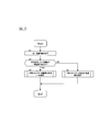
- FIG. 1 is a configuration diagram showing a predicted energy remaining amount guidance system according to the present embodiment.
- FIG. 2 is a diagram illustrating an example of a method for displaying information on the predicted passing point and the predicted battery remaining amount E bat when the vehicle is traveling on a general road.
- FIG. 3 is a diagram illustrating an example of a method of displaying information on the predicted passing point and the predicted battery remaining amount E bat when the vehicle is traveling on an expressway.
- FIG. 4 is a diagram illustrating an example of a method for displaying information on the predicted passing point and the predicted battery remaining amount E bat when a travel route of the vehicle is set.
- FIG. 1 is a configuration diagram showing a predicted energy remaining amount guidance system according to the present embodiment.
- FIG. 2 is a diagram illustrating an example of a method for displaying information on the predicted passing point and the predicted battery remaining amount E bat when the vehicle is traveling on a general road.
- FIG. 3 is a diagram illustrating an example of a method of displaying information on the predicted passing point and
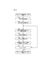
- FIG. 5 is a flowchart showing an example of a method for providing the user with information on the predicted passing point and the predicted battery remaining amount E bat using the predicted energy remaining amount guidance system in the present embodiment.
- FIG. 6 is a flowchart showing an example of the predicted remaining energy guide process (general road) in the present embodiment.
- FIG. 7 is a flowchart showing an example of the predicted remaining energy guide process (highway) in the present embodiment. 8, using the predicted remaining energy level guidance system in the present embodiment, in advance in the case where the traveling route of the vehicle is set, the method of providing information of the predicted passing point and the predicted remaining battery capacity E bat user It is a flowchart which shows an example.
- FIG. 1 is a configuration diagram showing a predicted energy remaining amount guidance system according to the present embodiment.
- the predicted remaining energy guidance system according to this embodiment includes an in-vehicle device 100 mounted on a vehicle driven by a battery and an information center 200 installed outside the vehicle.
- the in-vehicle device 100 can communicate with the information center 200 and can exchange information. Then, the in-vehicle device 100 wirelessly communicates with the information center 200 to acquire real-time traffic information on each road, for example, information on real-time travel speed in vehicles other than the host vehicle traveling on each road. 1 shows an example in which the in-vehicle device 100 communicates with one information center 200. However, in the present embodiment, the in-vehicle device 100 communicates with a plurality of information centers 200. It may be a simple configuration.
- the in-vehicle device 100 is mounted on a vehicle driven by a battery, and information on a predicted passing point where the vehicle is predicted to pass in the future, and a battery at the time of passing when it is assumed that the vehicle passes such a predicted passing point. the information of the remaining amount and is predicted battery remaining E bat, a device for displaying on the display 140, as shown in FIG. 1, a control unit 110, a communication device 120, and GPS130, a display 140, And a database 150.
- the control device 110, the communication device 120, the GPS 130, the display 140, and the database 150 are connected by a CAN (Controller Area Network) or other vehicle-mounted LAN so that information can be exchanged between them.
- CAN Controller Area Network
- the communication device 120 is a device for transmitting and receiving information to and from the communication device 220 provided in the information center 200 by wireless communication.
- the communication device 120 receives real-time traffic information on each road from the communication device 220 provided in the information center 200 by wireless communication.
- the real-time traffic information received here includes, for example, information on real-time vehicle speed of a vehicle currently traveling on each road.
- the database 150 is a database that stores own vehicle information, map information, and vehicle traffic information.
- the own vehicle information vehicle weight, vehicle size (width / height / length), air resistance coefficient (Cd value), motor drive efficiency, electrical component power consumption efficiency (cooler, audio power consumption efficiency, etc.)
- the map information includes, for example, map data including information on distances, gradients, and road types (types such as general roads and highways) of each road.
- vehicle traffic information for example, statistical data of vehicle speed information of vehicles on each road can be cited.
- the statistical data of the vehicle speed information of the vehicle on each road is, for example, data obtained by counting real-time vehicle speed information transmitted from the information center 200 for each road, or the vehicle speed when the host vehicle travels on each road. Are created based on data aggregated for each road.
- the control device 110 provided in the in-vehicle device 100 includes, for example, a ROM that stores a program, a CPU that executes the program stored in the ROM, and a RAM that functions as an accessible storage device.
- the control device 110 extracts a predicted passing point where the vehicle is predicted to pass in the future, calculates a predicted remaining battery level E bat when the vehicle is assumed to pass through the predicted passing point, and calculates the calculated predicted battery remaining level E.
- the bat information is provided to the user together with the predicted passing point information.
- Controller 110 extracts the predicted passing point described above, and performs the calculation of the predicted battery remaining E bat, the extracted information of the predicted passing point and the calculated predicted battery remaining E bat to provide users , A battery information acquisition function, a traveling environment information acquisition function, a predicted passing point extraction function, a power consumption calculation function, a remaining energy calculation function, and a display function.
- the control device 110 can execute each function by cooperation of software for realizing the above functions and the hardware described above.
- control device 110 each function realized by the control device 110 will be described.
- the battery information acquisition function of the control device 110 is a function of acquiring information on the battery provided in the vehicle using a sensor provided in the vehicle through CAN or other in-vehicle LAN.
- the information on the battery acquired by the battery remaining amount acquisition function includes information on the current battery remaining amount, and in addition to this, information on the current resistance deterioration degree may be included.
- the traveling environment information acquisition function of the control device 110 is a function for acquiring information on the current position, the current traveling direction, and the currently traveling road type in the vehicle as traveling environment information.
- a method of acquiring information on the current position of the vehicle for example, a method of receiving a radio wave transmitted from a positioning satellite by the GPS 130 may be mentioned.
- a method of acquiring information on the current traveling direction of the vehicle for example, the direction in which the vehicle is traveling is specified based on information on the current position of the vehicle detected every predetermined time, The method of setting it as a running direction is mentioned.
- a method for acquiring information on the type of road on which the vehicle is currently traveling for example, based on information on the current position of the vehicle detected every predetermined time
- One way is to identify the road that is currently running.
- a method of detecting the speed of the vehicle based on information on the current position of the vehicle detected every predetermined time and specifying whether the vehicle is traveling on a general road or an expressway is also included.
- the predicted passing point extraction function of the control device 110 is a function of extracting a predicted passing point where the vehicle is predicted to pass in the future based on the driving environment information acquired by the driving environment information acquiring function.
- a predicted passing point is extracted as follows. That is, first, the control device 110 determines whether the road on which the vehicle is currently traveling is a general road or an expressway based on the above-described traveling environment information. When the control device 110 determines that the road on which the vehicle is currently traveling is a general road, the control device 110 is predicted that the vehicle will pass the main intersection ahead of the traveling direction of the vehicle on the road in the future. As a predicted passing point.
- FIG. 2 is a diagram showing an example in which information on a predicted passing point is displayed on the display 140 when the road on which the vehicle is currently traveling is a general road.
- a map is shown in which a general road is indicated by a thin line and a highway is indicated by a thick line.
- a triangle icon on the map indicates the current position of the vehicle, and the top of the triangle icon is displayed.
- the direction of the corner indicates the traveling direction of the host vehicle.
- the main intersection (A intersection, B intersection, And C intersection) are extracted as predicted passing points where the vehicle is predicted to pass in the future.
- Examples of main intersections to be extracted as predicted passing points include intersections with national roads and roads with a predetermined number of lanes (for example, roads with four or more lanes) on the currently running road. It is done.
- the power consumption calculation function of the control device 110 is a function that calculates the predicted power consumption that is the power required for the vehicle to travel from the current position to the predicted passing point. Specifically, the control device 110 calculates the own vehicle information and the distance, gradient, and vehicle speed information statistics on the road from the current position of the vehicle to the predicted passing point from the information stored in the database 150. Data is read, and the predicted power consumption is calculated based on the read information.
- control device 110 first determines the vehicle information from the information stored in the database 150 and the distance, slope, and road on the road from the current position of the vehicle to the A intersection.
- the statistical data of the vehicle speed information of the vehicle is read, and the predicted power consumption from the current position of the vehicle to the A intersection is calculated based on the read information.
- control device 110 calculates a predicted power consumption from the current position of the vehicle to the B intersection and a predicted power consumption from the current position of the vehicle to the C intersection.
- the calculation of the predicted power consumption may be performed in consideration of traffic jam information, weather / outside temperature information, and the like.
- the traffic information, the weather / outside temperature information, and the like may be acquired by the control device 110 via the information center 200 or the Internet by the communication device 120, or the predicted power consumption may be calculated. Immediately before the execution, it may be acquired by a sensor provided in the vehicle.
- the calculation of the predicted power consumption is performed in consideration of the decrease in the battery capacity immediately before the calculation of the predicted power consumption, that is, the decrease in the battery capacity per unit time. Also good.
- Remaining energy level calculation function of the control unit 110 if the vehicle is assumed to pass through the prediction passing point, to calculate the a predicted value of the remaining battery capacity at the time of passing through the predicted passing point predicted remaining battery capacity E bat It is a function. Specifically, the control device 110 subtracts the predicted power consumption calculated by the power consumption calculation function from the current remaining battery level acquired by the battery information acquisition function, thereby passing the predicted passage point. The estimated battery remaining amount E bat is obtained.
- the control device 110 calculates a predicted battery remaining amount E bat_B at the B intersection and a predicted battery remaining amount E bat_C at the C intersection, respectively.
- the predicted battery remaining amount E bat may be calculated in consideration of information on the current resistance deterioration level of the battery.
- the control device 110 acquires information on the current resistance deterioration degree of the battery in addition to the information on the current battery remaining amount by the battery information acquisition function, and acquires the acquired battery remaining amount and resistance deterioration.
- the predicted battery remaining amount E bat is calculated based on the degree information and the predicted power consumption.
- the display function of the control device 110 displays the information on the predicted battery remaining amount E bat calculated by the remaining energy calculation function on the display 140 together with the information on the predicted predicted passing point, so that the predicted passing point and the predicted battery remaining amount are displayed. is a function of providing information amount E bat user.
- a map is displayed on the right side of the screen, and information on the A intersection, B intersection, and C intersection that are predicted passing points on the left side of the screen, for example, Information such as road name, intersection name, and distance from the current position of the vehicle is displayed.
- the information on the predicted battery remaining amount E bat calculated by the remaining energy calculation function together with the information on the predicted passing point is displayed on the battery 140. Displayed by icon.
- the battery icon in FIG. 2 indicates that the larger the white portion in the battery, the larger the predicted battery remaining amount E bat , and the user can visually recognize the amount of the predicted battery remaining amount E bat. It is like that.
- the information on the A intersection and the corresponding predicted battery remaining amount E bat_A , the information on the B intersection and the corresponding predicted battery remaining amount E bat_B , and the information on the C intersection are displayed on the display 140.
- the information and the corresponding predicted battery remaining amount E bat_C information it is possible to appropriately provide the user with the predicted passing point and the predicted battery remaining amount E bat information.
- the main intersection that the vehicle is predicted to pass in the future is extracted as the predicted passing point, and the predicted battery remaining amount E at the predicted passing point is extracted. Since the bat information is provided to the user together with the corresponding predicted passing point information, the user can easily plan a battery charging plan while referring to the predicted battery remaining amount E bat information at such a major intersection. Will be able to do.
- FIG. 2 shows an example in which a map is displayed on the right side of the screen on the display 140, and information on the predicted passing point and the predicted battery remaining amount E bat is displayed on the left side of the screen.
- the display on the display 140 is not limited to such an example, and for example, information on the predicted passing point and the predicted battery remaining amount E bat may be displayed superimposed on the map.
- the predicted passing point information is displayed in a manner in which the position of the predicted passing point can be recognized, and the predicted battery remaining amount E bat is displayed. It is preferable to display the information in association with the predicted passing point information. For example, in FIG. 2, by displaying a line segment connecting the information of the A intersection and the position of the A intersection on the map on the display 140, the predicted passing point information is displayed as the predicted passing point position. It can be displayed in a recognizable manner. Further, as shown in FIG.
- the periphery of the information of the predicted passing point by displaying the battery icon that indicates the information of the predicted battery remaining E bat, the predicted passing point information of the predicted battery remaining E bat It can be displayed in association with information. Accordingly, in the present embodiment, the user can intuitively recognize the information of the predicted passing point and the predicted battery remaining amount E bat , and more efficiently the thought passing point and the predicted battery remaining amount. E bat information can be provided.
- the control device 110 acquires charging facility information via the information center 200 or the Internet using the communication device 120, and extracts charging facilities existing within a predetermined distance from the predicted passing point based on the acquired information.
- the charging facility information can be displayed by a method of arranging an icon representing the charging facility at a position where the extracted charging facility is present on the map of the display 140.
- the predetermined distance is not particularly limited, and can be, for example, about 1 to 10 km.
- the charging facility information on the display 140 when the user operates the in-vehicle device 100 and selects the charging facility from the display on the display 140, the detailed information of the selected charging facility is displayed. It is good also as a structure which is displayed.
- Detailed information on the charging facility that is displayed includes, for example, navigation information such as the distance and required time from the current position of the vehicle to the selected charging facility, information on whether or not the charging facility is open, and whether or not it is currently open , Facility information such as the charger type and the number of charging ports.
- the control device 110 when displaying charging facility information on the display 140, the control device 110 allows the vehicle to pass through the predicted passing point among charging facilities existing within a predetermined distance from the predicted passing point. It is good also as displaying only the charging facility which can be utilized in the prediction passage time in the case of doing. That is, the control device 110 calculates in advance a predicted passing time when it is assumed that the predicted passing point is passed, and then exists within a predetermined distance from the predicted passing point and can be used for the predicted passing time.
- the charging facility may be extracted, and only the extracted charging facility may be displayed on the display 140.
- examples of the charging facility that can be used include a charging facility that is operating even at the predicted passage time.
- the user in addition to the information on the predicted passing point and the predicted battery remaining amount E bat , the user can obtain information on the charging facility that is actually highly available when the vehicle reaches the predicted passing point. As a result, the user can make a plan for charging the battery with peace of mind.
- the information center 200 is a server for distributing traffic information such as real-time vehicle speed of a vehicle currently traveling on each road to the in-vehicle device 100.
- the information center 200 includes a control device 210 and a communication device 220.
- the communication device 220 is a device for transmitting and receiving information to and from the communication device 120 provided in the in-vehicle device 100 by wireless communication. Specifically, the communication device 220 receives real-time vehicle speed information acquired by the control device 210 for each road, and the received information is provided in the in-vehicle device 100 according to a command from the control device 210. 120 is transmitted.
- the control device 210 includes, for example, a ROM that stores a program, a CPU that executes the program stored in the ROM, and a RAM that functions as an accessible storage device.
- the control device 210 acquires real-time vehicle speed information of the currently traveling vehicle for each road, and the acquired vehicle speed information is communicated to the communication device 120 included in the in-vehicle device 100 via the communication device 220. Send to.
- the method by which the control device 210 acquires real-time vehicle speed information is not particularly limited. For example, a method of receiving real-time vehicle speed information of a vehicle on which the vehicle-mounted device 100 is mounted from the vehicle-mounted device 100, For example, a method of collecting vehicle speed information acquired by a sensor installed on a road by wireless communication.
- control device 210 uses the communication device 220 to send traffic information, weather / outside air temperature information, charging facility information, and the like acquired via the Internet. You may transmit to the communication apparatus 120 with which 100 is equipped.
- information on the predicted passing point and the predicted battery remaining amount E bat is provided to the user as described above.
- the control device 110 extracts a predicted passing point by the predicted passing point extracting function as follows. That is, first, the control device 110 determines whether the road on which the vehicle is currently traveling is a general road or an expressway based on the travel environment information acquired by the travel environment information acquisition function. When the control device 110 determines that the road on which the vehicle is currently traveling is a highway, the interchange (IC), the service area (SA), which is ahead of the traveling direction of the vehicle on the road, And a parking area (PA) etc. are extracted as a predicted passing point.
- the interchange IC
- SA service area
- PA parking area
- FIG. 3 is a diagram showing an example in which information of predicted passing points is displayed on the display 140 when the road on which the vehicle is currently traveling is an expressway.
- ⁇ IC, ⁇ SA, and ⁇ IC ahead of the traveling direction of the vehicle on the road are Extracted as a predicted passing point.
- control device 110 calculates a predicted power consumption that is an amount of power required for the vehicle to travel from the current position to the predicted passing point by the power consumption calculation function. For example, in the scene shown in FIG. 3, the control device 110 first determines the vehicle information and the distance, gradient, and vehicle on the road from the current position of the vehicle to ⁇ IC from the information stored in the database 150. And the statistical data of the vehicle speed information is calculated, and the predicted power consumption from the current position of the vehicle to ⁇ IC is calculated based on the read information. Similarly, control device 110 calculates a predicted power consumption amount from the current position of the vehicle to ⁇ SA and a predicted power consumption amount from the current position of the vehicle to ⁇ IC.
- the control device 110 calculates the predicted remaining battery level E bat at the time when the vehicle passes the predicted passing point by the remaining energy calculating function. For example, in the scene shown in FIG. 3, since the predicted power consumption from the current position of the vehicle to ⁇ IC is calculated by the power consumption calculation function as described above, the current remaining battery level acquired by the battery information acquisition function is calculated. Thus, the predicted battery remaining amount E bat — ⁇ at ⁇ IC can be obtained by subtracting the predicted power consumption from the current position of the vehicle to ⁇ IC. Similarly, control device 110 calculates predicted battery remaining amount E bat — ⁇ in ⁇ SA and predicted battery remaining amount E bat — ⁇ in ⁇ IC , respectively.
- the control device 110 extracts a predicted passage point by the predicted passage point extraction function as follows. That is, first, the control device 110 specifies a section of a general road and a section of an expressway on the travel route of the vehicle. Then, the control device 110 extracts the above-mentioned main intersection as a predicted passing point in the section of the general road on the travel route, while predicting IC, SA, PA, etc. in the section of the expressway on the travel route. Extract as a passing point.
- FIG. 4 is a diagram showing an example in which information of predicted passing points is displayed on the display 140 when a travel route is set in advance in the vehicle.
- the travel route set for the vehicle is indicated by a hollow line.
- the A intersection is predicted in the section of the general road on the travel route (that is, the section from the current position of the vehicle to ⁇ IC and the section after ⁇ IC in FIG. 4).
- ⁇ IC, ⁇ SA, and ⁇ IC are extracted as predicted passing points in the section of the expressway on the travel route (that is, the section from ⁇ IC to ⁇ IC in FIG. 4).
- control device 110 calculates the predicted power consumption from the current position of the vehicle to each predicted passing point by the power consumption calculation function. For example, in the scene shown in FIG. 4, with the above-described method, the predicted power consumption up to the A intersection, the predicted power consumption up to ⁇ IC, the predicted power consumption up to ⁇ SA, and ⁇ IC using the current position of the vehicle as a starting point. The predicted power consumption up to is calculated.
- the control device 110 calculates the predicted battery remaining amount E bat at each predicted passing point by the energy remaining amount calculating function. For example, in the scene shown in FIG. 4, by the method described above, prediction in A intersection battery remaining E Bat_A, predictive battery remaining amount ⁇ IC E bat_ ⁇ , prediction in ⁇ SA battery remaining E Bat_beta, and prediction in ⁇ IC battery level E bat — ⁇ is calculated.
- a travel route of the vehicle is set in advance
- such a predicted pass point is extracted from the set travel route in accordance with the road type.
- the information on the predicted battery remaining amount E bat at the predicted passing point can be provided to the user, so that the user can easily make a battery charging plan on the travel route.
- FIG. 5 is a method for providing a user with information on a predicted passing point and a predicted remaining battery level E bat using the predicted remaining energy level guidance system in the present embodiment when a travel route is not set for the vehicle. It is a flowchart which shows an example.
- step S1 the control device 110 acquires the current position of the vehicle, the current travel direction, and the information on the currently traveling road type as travel environment information by the travel environment information acquisition function.
- step S2 the control device 110 determines whether the road on which the vehicle is currently traveling is a general road based on the travel environment information acquired in step S1. If it is determined in step S2 that the road on which the vehicle is currently traveling is a general road, the process proceeds to step S3. On the other hand, if it is determined in step S2 that the road on which the vehicle is currently traveling is not a general road, the process proceeds to step S4.
- step S2 If it is determined in step S2 that the road on which the vehicle is currently traveling is a general road, the process proceeds to step S3.
- step S3 the control device 110 performs the predicted energy remaining amount guidance process (general road). Then, extraction of the predicted passing point and calculation of the predicted battery remaining amount E bat are performed, and information on the predicted passing point and the predicted battery remaining amount E bat is displayed on the display 140.
- FIG. 6 is a flowchart showing an example of the predicted remaining energy guide process (general road).
- the predicted energy remaining amount guidance process (general road) will be described with reference to FIG.
- step S301 shown in FIG. 6 information on the current position of the vehicle is acquired from the travel environment information acquired in step S1.
- step S302 information on the current traveling direction of the vehicle is acquired from the traveling environment information acquired in step S1.
- step S303 the control device 110 uses the predicted passing point extraction function to calculate a predicted power consumption amount based on the current position and current travel direction information of the vehicle acquired in steps S301 and S302. Is identified. Specifically, the control device 110 refers to the map information stored in the database 150 and exists on the general road on which the vehicle is currently traveling, starting from the current position of the vehicle and ahead of the current traveling direction. The nearest main intersection, for example, an intersection with a national road or an intersection with a predetermined number of lanes is specified.
- step S304 the control device 110 calculates the predicted power consumption, which is the amount of power required for the vehicle to travel from the current position to the main intersection specified in step S303, using the power consumption calculation function. Specifically, the control device 110 calculates the own vehicle information and the distance, gradient, and vehicle speed information statistics on the road from the current position of the vehicle to the predicted passing point from the information stored in the database 150. Data is read, and the predicted power consumption is calculated based on the read information.
- step S305 when it is assumed that the vehicle passes the main intersection, a predicted battery remaining amount E bat that is a remaining battery amount at the time of passing the main intersection is calculated. Specifically, first, the control device 110 acquires the current remaining battery level of the vehicle using the battery information acquisition function. Next, the control device 110 subtracts the predicted power consumption calculated in step S304 from the current remaining battery level by using the remaining energy calculation function, so that the remaining battery level at the time of passing the predicted passing point is reduced. A predicted battery remaining amount E bat which is an amount is obtained.
- step S306 the control device 110 displays the information on the predicted battery remaining amount E bat calculated in step S305 on the display 140 together with the information on the main intersection specified in step S303 by the display function.
- step S307 the control unit 110, the predicted battery remaining E bat calculated in step S305 it is determined whether the predetermined threshold value E 1 less.
- the predetermined threshold E 1 is a main intersection farther from the current position of the vehicle (that is, a main intersection having a smaller predicted battery remaining amount E bat ) in the predicted energy remaining amount guidance process (general road). ) Is a threshold value for determining whether or not to further specify.
- the predetermined threshold value E 1 is not particularly limited, but may be a value of about 5 to 20% of the full charge capacity of the battery provided in the vehicle, for example.
- step S307 if the predicted battery remaining E bat is determined that the predetermined threshold value E 1 is smaller than ends predicted remaining energy level guidance processing (general road), then the flowchart shown in FIG. 5 Return to this processing.
- step S307 if the predicted battery remaining E bat is determined to a predetermined threshold E 1 or more, the process returns to step S303.
- the control device 110 refers to the map information stored in the database 150, and on the general road on which the vehicle is currently traveling, the current driving is started from the already extracted main intersection. Identify the next major intersection ahead of the direction. Thereafter, based on the main intersection newly extracted in step S303, the processes in steps S304 to S307 described above are executed.
- step S4 the control device 110 provides the predicted remaining energy guidance. treatment (motorway), extraction of the predicted passing point, and performs calculation of the predicted battery remaining E bat, to display information such predictions passing point and the predicted remaining battery capacity E bat on the display 140.
- FIG. 7 is a flowchart showing an example of the predicted energy remaining amount guide process (highway).
- the predicted energy remaining amount guidance process highway
- control device 110 acquires information on the current position and the current traveling direction of the vehicle, as in steps S301 and S302 described above.
- step S403 the control device 110 uses the predicted passing point extraction function to calculate the predicted power consumption based on the information on the current position and the current traveling direction of the vehicle acquired in steps S401 and 402, Specify SA or PA. Specifically, the control device 110 refers to the map information stored in the database 150 and exists on the highway where the vehicle is currently traveling, starting from the current position of the vehicle and ahead of the current traveling direction. Identify the nearest IC, SA, or PA
- step S404 as in step S304 described above, the control device 110 uses the power consumption calculation function to calculate the amount of power necessary for the vehicle to travel from the current position to the IC, SA, or PA specified in step S403. A certain predicted power consumption is calculated.
- control device 110 passes such IC, SA, or PA when it is assumed that the vehicle passes IC, SA, or PA specified in step S403.
- a predicted battery remaining amount E bat that is a remaining battery amount at the time is calculated.
- step S406 the control device 110 displays the information of the predicted battery remaining amount E bat calculated in step S405 on the display 140 together with the IC, SA, or PA information specified in step S403 by a display function.
- step S407 the control device 110 determines whether or not the IC, SA, or PA specified in step S403 is a facility closest to the expressway terminal.
- IC, SA which is located immediately before the entrance / exit provided at the end of the expressway (the node between the expressway and the general road, or the node between the expressways) Or PA etc. are mentioned.
- step S407 if it is determined that the IC, SA, or PA specified in step S403 is the nearest facility at the end of the expressway, the predicted energy remaining amount guidance process (expressway) is terminated, Thereafter, the process returns to the flowchart shown in FIG. On the other hand, if it is determined in step S407 that the IC, SA, or PA specified in step S403 is not the nearest facility at the highway end, the process proceeds to step S408.
- step S408 the control unit 110, the predicted battery remaining E bat calculated in step S405 it is determined whether or not a predetermined threshold E 2 less.
- the predetermined threshold E 2 may be the same value as the threshold value E 1 as described above, the value may be different. Then, in step S408, if the predicted battery remaining E bat is determined that the predetermined threshold E 2 less terminates predicted remaining energy level guidance processing (motorway), then the flowchart shown in FIG. 5 Return to this processing. On the other hand, in step S408, if the predicted battery remaining E bat is determined to a predetermined threshold E 2 or more, the process returns to step S403.
- step S403 the control device 110 refers to the map information stored in the database 150, and starts from the IC, SA, or PA that has already been extracted on the highway on which the vehicle is currently traveling. The next IC, SA, or PA existing ahead of the current traveling direction is specified. Thereafter, based on the IC, SA, or PA newly extracted in step S403, the processes in steps S404 to S408 described above are executed.
- the control device 110 extracts a predicted intersection remaining point E bat at a predicted passing point after extracting a predicted intersection such as a major intersection or IC, SA, or PA, and extracts it.
- the information of the predicted passing point and the calculated predicted battery remaining amount E bat is provided to the user.
- the information of the predicted battery remaining E bat at the predicted passing point which the vehicle is expected to pass the user is predicted remaining battery in the running route of the vehicle Information on the amount E bat can be obtained, and a battery charging plan can be easily made.
- the user by providing the user with information on the predicted passing point and the predicted battery remaining amount E bat on the display 140, the user can predict the predicted passing point and the predicted battery remaining amount E bat. information bat, intuitively will be able to recognize, the user can perform more efficiently virtual guidance information of the passing point and the predicted remaining battery capacity E bat.
- FIG. 8 provides the user with information on the predicted passing point and the predicted battery remaining amount E bat using the predicted energy remaining amount guidance system in the present embodiment when a travel route is set in advance for the vehicle. It is a flowchart which shows an example of a method.
- step S501 shown in FIG. 8 the control device 110 acquires travel environment information including information on the current position of the vehicle by the travel environment information acquisition function.
- step S502 the control device 110 acquires information on a travel route set for the vehicle.
- a travel route set for the vehicle For example, in the present embodiment, a configuration in which a user operates the in-vehicle device 100 to set a travel route of the vehicle and store the set travel route in a memory or the like provided in the control device 110 may be adopted. In this case, the control device 110 reads the information stored in such a memory or the like to acquire the travel route information.
- step S503 the control device 110 extracts, from the travel route, a predicted passage point that is a target for calculating the predicted power consumption, based on the travel route information acquired in step S502, using the predicted passage point extraction function. .
- the control device 110 specifies a section of a general road and a section of an expressway on the travel route acquired in step S502.
- the control device 110 extracts the main intersection from the section of the general road on the travel route, extracts IC, SA, PA, or the like from the section of the expressway on the travel route, and extracts the extracted main intersection, IC, Among the SA and PA, the closest position starting from the current position of the vehicle is specified as the predicted passing point.
- step S504 as in step S304 described above, the control device 110 uses the power consumption calculation function to calculate the amount of power necessary for the vehicle to travel from the current position to the predicted passing point specified in step S503. Calculate the predicted power consumption.
- step S505 similarly to step S305 described above, the control device 110 assumes that the vehicle passes through the predicted passing point, and when the vehicle passes the predicted passing point, the predicted battery remaining amount E bat that is the remaining battery level at the time of passing through the predicted passing point. Is calculated.
- step S506 the control device 110 displays the information on the predicted battery remaining amount E bat calculated in step S505 on the display 140 together with the information on the predicted passing point specified in step S503, using the display function.
- step S507 the control unit 110, the predicted battery remaining E bat calculated in step S505 it is determined whether the predetermined threshold value E 3 or less.
- the predetermined threshold value E 3 may be the same value as the threshold value E 1 or the threshold value E 2 described above, or may be a different value. Then, in step S507, the if the predicted battery remaining E bat is determined that the predetermined threshold value E 3 is smaller than, the process ends. On the other hand, in step S507, the if the predicted battery remaining E bat is determined to a predetermined threshold E 3 or more, the process returns to step S503.
- step S503 the control device 110 exists ahead of the current travel direction on the travel route, starting from the already extracted predicted passing point, on the travel route based on the travel route information acquired in step S502.
- the next major intersection, IC, SA, or PA is identified as the predicted passing point.
- the above-described processing of steps S504 to S507 is executed.
- the control device 110 identifies a general road section and a highway section on the travel route, and then predicts a passing point according to each of the general road section and the highway section. Further, the predicted battery remaining amount E bat at the predicted passing point is calculated, and information on the extracted predicted passing point and the calculated predicted battery remaining amount E bat is provided to the user.
- a travel route of the vehicle is set in advance
- such a predicted pass point is extracted from the set travel route in accordance with the road type.
- the information on the predicted battery remaining amount E bat at the predicted passing point can be provided to the user, so that the user can easily make a battery charging plan on the travel route.
- the control device 110 has shown an example in which the predicted passing point is extracted from the road (general road or highway) on which the vehicle is currently traveling. However, the vehicle is currently traveling.
- the predicted passing point may be extracted not only from the existing road but also from other roads connected to this road.
- the control device 110 sets a predetermined area toward the current traveling direction starting from the current position of the vehicle based on the driving environment information acquired by the driving environment information acquisition function, and predicts a passing point from the set predetermined area. May be extracted.
- the predetermined area is not particularly limited. For example, a fan-shaped area having an angle of about 10 to 30 degrees with the current traveling direction as the center can be set starting from the current position in the vehicle.
- step S403 the entrance / exit of the expressway can be specified as the predicted passing point, and when the entrance / exit of the expressway is specified as the predicted passing point, In step S407, instead of the above-described determination, it is determined whether or not the highway doorway specified as the predicted passing point is the doorway provided at the end of the highway.
- control device 110 has shown an example in which information on the predicted passing point and the predicted battery remaining amount E bat is provided to the user by displaying the information on the display 140.
- the method of providing the battery remaining amount E bat information to the user is not particularly limited, and for example, a method of providing by voice announcement through a speaker may be used.
- the driving energy serving as the power source of the vehicle is a battery
- the driving energy for example, gasoline, light oil, gasoline or light oil and battery combined energy
- it may be a methanol fuel of a fuel cell or a gaseous fuel such as high-pressure hydrogen gas.
- the energy supply spot for supplying driving energy to the vehicle is illustrated as an example of a charging facility.
- the energy supply spot may be anything, such as a gas station or a hydrogen station. There may be.
- the in-vehicle device 100 and the information center 200 are configured to communicate directly, but the in-vehicle device 100 transmits and receives information to and from the information center 200 using cloud computing or the like. You may go.
- the IO hand instead of the in-vehicle device 100, the IO hand performs the extraction of the predicted passing point and the calculation of the predicted battery remaining amount E bat with the personal computer or the smartphone, as described above, and the predicted passing point and the predicted battery It is good also as a structure which provides a user with the information of remaining amount Ebat .
- control device 110 corresponds to an acquisition unit, an extraction unit, a calculation unit, a provision unit, and a detection unit of the present invention.
Abstract
Priority Applications (9)
| Application Number | Priority Date | Filing Date | Title |
|---|---|---|---|
| RU2016106102A RU2016106102A (ru) | 2013-07-25 | 2014-06-04 | Система для оповещения о прогнозируемом оставшемся количестве энергии |
| CN201480051927.6A CN105556245B (zh) | 2013-07-25 | 2014-06-04 | 预测能量余量引导系统 |
| JP2015528183A JP6090449B2 (ja) | 2013-07-25 | 2014-06-04 | 予測エネルギー残量案内システム |
| US14/907,099 US10166880B2 (en) | 2013-07-25 | 2014-06-04 | System for announcing predicted remaining amount of energy |
| EP14829170.1A EP3026395A1 (fr) | 2013-07-25 | 2014-06-04 | Système de guidage à prévision d'énergie restante |
| CA2919318A CA2919318A1 (fr) | 2013-07-25 | 2014-06-04 | Systeme d'annonce de quantite d'energie restante prevue |
| MX2016000955A MX2016000955A (es) | 2013-07-25 | 2014-06-04 | Sistema para anunciar una cantidad restante predicha de energia. |
| KR1020167004478A KR20160034377A (ko) | 2013-07-25 | 2014-06-04 | 예측 에너지 잔량 안내 시스템 |
| US16/044,782 US10906424B2 (en) | 2013-07-25 | 2018-07-25 | System for announcing predicted remaining amount of energy |
Applications Claiming Priority (2)
| Application Number | Priority Date | Filing Date | Title |
|---|---|---|---|
| JP2013-154300 | 2013-07-25 | ||
| JP2013154300 | 2013-07-25 |
Related Child Applications (2)
| Application Number | Title | Priority Date | Filing Date |
|---|---|---|---|
| US14/907,099 A-371-Of-International US10166880B2 (en) | 2013-07-25 | 2014-06-04 | System for announcing predicted remaining amount of energy |
| US16/044,782 Continuation US10906424B2 (en) | 2013-07-25 | 2018-07-25 | System for announcing predicted remaining amount of energy |
Publications (1)
| Publication Number | Publication Date |
|---|---|
| WO2015011997A1 true WO2015011997A1 (fr) | 2015-01-29 |
Family
ID=52393050
Family Applications (1)
| Application Number | Title | Priority Date | Filing Date |
|---|---|---|---|
| PCT/JP2014/064858 WO2015011997A1 (fr) | 2013-07-25 | 2014-06-04 | Système de guidage à prévision d'énergie restante |
Country Status (9)
| Country | Link |
|---|---|
| US (2) | US10166880B2 (fr) |
| EP (1) | EP3026395A1 (fr) |
| JP (1) | JP6090449B2 (fr) |
| KR (1) | KR20160034377A (fr) |
| CN (1) | CN105556245B (fr) |
| CA (1) | CA2919318A1 (fr) |
| MX (1) | MX2016000955A (fr) |
| RU (1) | RU2016106102A (fr) |
| WO (1) | WO2015011997A1 (fr) |
Cited By (2)
| Publication number | Priority date | Publication date | Assignee | Title |
|---|---|---|---|---|
| JP2018072093A (ja) * | 2016-10-26 | 2018-05-10 | トヨタ自動車株式会社 | エネルギー消費量予測装置及びエネルギー消費量予測方法 |
| CN110667428A (zh) * | 2019-09-26 | 2020-01-10 | 东南大学 | 一种基于实时定位数据的电动汽车充电站推荐方法 |
Families Citing this family (10)
| Publication number | Priority date | Publication date | Assignee | Title |
|---|---|---|---|---|
| CN105556245B (zh) * | 2013-07-25 | 2020-03-06 | 日产自动车株式会社 | 预测能量余量引导系统 |
| KR102297167B1 (ko) * | 2015-03-18 | 2021-09-01 | 에스케이플래닛 주식회사 | 위치 측정이 이루어지는 단말 및 그 동작 방법 |
| CN106875711A (zh) * | 2017-03-10 | 2017-06-20 | 李金良 | 车辆事故告警装置、系统、方法及机动车 |
| JP2020142710A (ja) * | 2019-03-07 | 2020-09-10 | 本田技研工業株式会社 | 車両制御システム、車両制御方法、及びプログラム |
| CN110823243A (zh) * | 2019-11-21 | 2020-02-21 | 中通客车控股股份有限公司 | 一种燃料电池车辆加氢系统、方法及车辆 |
| CN111046342B (zh) * | 2019-12-16 | 2023-07-21 | 潍柴动力股份有限公司 | 一种能量补给站数据处理方法、装置及系统 |
| CN112078431B (zh) * | 2020-08-19 | 2022-02-25 | 大众问问(北京)信息科技有限公司 | 一种车辆能耗预测和能源补充方法及相关设备 |
| CN112406874B (zh) * | 2020-11-27 | 2022-04-22 | 深圳供电局有限公司 | 一种电动汽车远距离充电辅助决策方法 |
| US20220309931A1 (en) * | 2021-03-23 | 2022-09-29 | Honeywell International Inc. | Systems and methods for guiding vehicles to charging points |
| CN113380052B (zh) * | 2021-06-08 | 2022-07-15 | 重庆大学 | 基于etc数据的驶入服务区车流量预测方法及装置 |
Citations (4)
| Publication number | Priority date | Publication date | Assignee | Title |
|---|---|---|---|---|
| JP2001183150A (ja) * | 1999-10-15 | 2001-07-06 | Nissan Motor Co Ltd | 走行パターン生成装置 |
| JP2010210271A (ja) | 2009-03-06 | 2010-09-24 | Nissan Motor Co Ltd | ナビゲーション装置及び目的地到達可否判定方法 |
| JP2012211888A (ja) * | 2011-12-08 | 2012-11-01 | Pioneer Electronic Corp | 表示制御装置、表示制御方法およびサーバ |
| JP2013002932A (ja) * | 2011-06-16 | 2013-01-07 | Hitachi Automotive Systems Ltd | ナビゲーションにおける時間予測方法 |
Family Cites Families (23)
| Publication number | Priority date | Publication date | Assignee | Title |
|---|---|---|---|---|
| US20100094496A1 (en) * | 2008-09-19 | 2010-04-15 | Barak Hershkovitz | System and Method for Operating an Electric Vehicle |
| JP5120204B2 (ja) * | 2008-10-28 | 2013-01-16 | アイシン・エィ・ダブリュ株式会社 | 走行案内装置、走行案内方法及びコンピュータプログラム |
| JP5077195B2 (ja) * | 2008-11-11 | 2012-11-21 | アイシン・エィ・ダブリュ株式会社 | 走行支援装置、方法およびプログラム |
| JP5774592B2 (ja) * | 2009-09-15 | 2015-09-09 | ケーピーアイティ テクノロジーズ リミテッド | 予測駆動範囲に基づくハイブリッド車のモータ補助 |
| JP4987054B2 (ja) | 2009-09-30 | 2012-07-25 | 中国電力株式会社 | 逆潮流低減システム及び逆潮流低減方法 |
| KR101231515B1 (ko) * | 2010-06-30 | 2013-02-07 | 기아자동차주식회사 | 주행경로의 연료량 계산 시스템 및 그 방법 |
| JP4905610B2 (ja) * | 2010-07-09 | 2012-03-28 | トヨタ自動車株式会社 | 情報提供装置 |
| JP5615090B2 (ja) | 2010-08-20 | 2014-10-29 | 三菱重工業株式会社 | 管理装置、管理方法、コンピュータプログラム、車載器及び通信方法 |
| JP5395764B2 (ja) | 2010-08-24 | 2014-01-22 | 株式会社日立製作所 | 電気自動車の充電制御方法、充電監視制御センタ、車載カーナビ装置、および電力系統安定化システム |
| EP2428770B1 (fr) * | 2010-09-08 | 2013-04-24 | Harman Becker Automotive Systems GmbH | Système de navigation de véhicule |
| JP2012066705A (ja) | 2010-09-24 | 2012-04-05 | Nissan Motor Co Ltd | 情報提供システムおよび情報提供方法 |
| CN103429989B (zh) | 2010-12-30 | 2017-10-20 | 泰为信息科技公司 | 具有受限资源路线规划最佳化器的导航系统及其操作方法 |
| DE112012000447T5 (de) | 2011-01-12 | 2013-10-10 | Cummins Intellectual Property, Inc. | System und Verfahren eines Kraftstoffquantitätsmanagements eines Fahrzeugs |
| JP5474254B2 (ja) * | 2011-02-24 | 2014-04-16 | 三菱電機株式会社 | ナビゲーション装置、推奨速度演算装置及び推奨速度提示装置 |
| WO2012131963A1 (fr) * | 2011-03-30 | 2012-10-04 | パイオニア株式会社 | Dispositif de commande d'affichage, terminal, système de commande d'affichage et procédé de commande d'affichage |
| DE102011015777A1 (de) | 2011-04-01 | 2012-10-04 | Volkswagen Aktiengesellschaft | Verfahren und Vorrichtung zum Durchführen einer Reiseroutenplanung für ein Fahrzeug |
| JP5873986B2 (ja) | 2011-09-20 | 2016-03-01 | パナソニックIpマネジメント株式会社 | 充電システム、サーバ装置、及び、サーバ装置のプログラム |
| DE102011114549A1 (de) * | 2011-09-30 | 2013-04-04 | Audi Ag | Verfahren zum Betreiben eines mit einem Elektromotor antreibbaren Fahrzeugs |
| EP2894436A4 (fr) * | 2012-09-03 | 2016-04-27 | Hitachi Ltd | Système d'aide au chargement et procédé d'aide au chargement destinés à un véhicule électrique |
| US9759572B2 (en) * | 2012-11-06 | 2017-09-12 | Mitsubishi Electric Corporation | Navigation apparatus that calculates one or more travelable ranges for an electric vehicle |
| JP5928320B2 (ja) * | 2012-12-07 | 2016-06-01 | 株式会社日立製作所 | 電気自動車向けナビゲーションシステム |
| CN105556245B (zh) * | 2013-07-25 | 2020-03-06 | 日产自动车株式会社 | 预测能量余量引导系统 |
| JP5855163B2 (ja) * | 2014-05-13 | 2016-02-09 | 三菱電機株式会社 | 車両用エネルギーマネジメント装置 |
-
2014
- 2014-06-04 CN CN201480051927.6A patent/CN105556245B/zh active Active
- 2014-06-04 JP JP2015528183A patent/JP6090449B2/ja active Active
- 2014-06-04 US US14/907,099 patent/US10166880B2/en active Active
- 2014-06-04 MX MX2016000955A patent/MX2016000955A/es unknown
- 2014-06-04 KR KR1020167004478A patent/KR20160034377A/ko not_active Application Discontinuation
- 2014-06-04 CA CA2919318A patent/CA2919318A1/fr not_active Abandoned
- 2014-06-04 EP EP14829170.1A patent/EP3026395A1/fr not_active Ceased
- 2014-06-04 RU RU2016106102A patent/RU2016106102A/ru not_active Application Discontinuation
- 2014-06-04 WO PCT/JP2014/064858 patent/WO2015011997A1/fr active Application Filing
-
2018
- 2018-07-25 US US16/044,782 patent/US10906424B2/en active Active
Patent Citations (4)
| Publication number | Priority date | Publication date | Assignee | Title |
|---|---|---|---|---|
| JP2001183150A (ja) * | 1999-10-15 | 2001-07-06 | Nissan Motor Co Ltd | 走行パターン生成装置 |
| JP2010210271A (ja) | 2009-03-06 | 2010-09-24 | Nissan Motor Co Ltd | ナビゲーション装置及び目的地到達可否判定方法 |
| JP2013002932A (ja) * | 2011-06-16 | 2013-01-07 | Hitachi Automotive Systems Ltd | ナビゲーションにおける時間予測方法 |
| JP2012211888A (ja) * | 2011-12-08 | 2012-11-01 | Pioneer Electronic Corp | 表示制御装置、表示制御方法およびサーバ |
Non-Patent Citations (1)
| Title |
|---|
| See also references of EP3026395A4 |
Cited By (4)
| Publication number | Priority date | Publication date | Assignee | Title |
|---|---|---|---|---|
| JP2018072093A (ja) * | 2016-10-26 | 2018-05-10 | トヨタ自動車株式会社 | エネルギー消費量予測装置及びエネルギー消費量予測方法 |
| US11358481B2 (en) | 2016-10-26 | 2022-06-14 | Toyota Jidosha Kabushiki Kaisha | Energy consumption predicting device and energy consumption predicting method |
| CN110667428A (zh) * | 2019-09-26 | 2020-01-10 | 东南大学 | 一种基于实时定位数据的电动汽车充电站推荐方法 |
| CN110667428B (zh) * | 2019-09-26 | 2022-03-11 | 东南大学 | 一种基于实时定位数据的电动汽车充电站推荐方法 |
Also Published As
| Publication number | Publication date |
|---|---|
| CN105556245A (zh) | 2016-05-04 |
| KR20160034377A (ko) | 2016-03-29 |
| CA2919318A1 (fr) | 2015-01-29 |
| CN105556245B (zh) | 2020-03-06 |
| EP3026395A4 (fr) | 2016-06-01 |
| US10906424B2 (en) | 2021-02-02 |
| MX2016000955A (es) | 2016-05-09 |
| RU2016106102A (ru) | 2017-08-30 |
| JPWO2015011997A1 (ja) | 2017-03-02 |
| US10166880B2 (en) | 2019-01-01 |
| US20180345814A1 (en) | 2018-12-06 |
| US20160159241A1 (en) | 2016-06-09 |
| JP6090449B2 (ja) | 2017-03-08 |
| EP3026395A1 (fr) | 2016-06-01 |
Similar Documents
| Publication | Publication Date | Title |
|---|---|---|
| JP6090449B2 (ja) | 予測エネルギー残量案内システム | |
| EP2369298B1 (fr) | Dispositif de guidage de chargement de véhicule, procédé de guidage de chargement de véhicule et produit de programme informatique | |
| CN111220168A (zh) | 一种电动汽车充电路径规划方法、装置和存储介质 | |
| JP6284115B2 (ja) | 電子装置、電子システム、経路探索方法および経路探索プログラム | |
| US20130282264A1 (en) | Systems and methods for obtaining and using traffic flow information | |
| JP4886099B1 (ja) | 表示制御装置、端末、表示制御システムおよび表示制御方法 | |
| WO2014103402A1 (fr) | Dispositif de fourniture d'informations de véhicule | |
| JP2012026813A (ja) | カーナビゲーション装置 | |
| US11175153B2 (en) | Pedestrian and vehicle route optimization | |
| JP7036522B2 (ja) | 電子装置、電子システム、経路探索方法および経路案内プログラム | |
| JP2019096280A (ja) | 情報提供システム、方法及びプログラム | |
| JP2015161604A (ja) | ナビゲーション装置及びナビゲーションプログラム | |
| JP2009104415A (ja) | 車両走行履歴情報提供システム | |
| JP6268751B2 (ja) | 目的地情報提供システム及び方法、並びにコンピュータプログラム | |
| JP2014020936A (ja) | 車両用情報提供システム | |
| KR101064826B1 (ko) | 다자간의 주행 정보를 이용하여 교통정보를 제공하는 내비게이션 제어 장치 및 그 방법 | |
| CN112185157B (zh) | 路边停车位检测方法、系统、计算机设备及存储介质 | |
| JP5433670B2 (ja) | 表示制御装置、表示制御方法およびサーバ | |
| CN113537615B (zh) | 一种充电车辆的预测方法、装置及电子设备 | |
| WO2014162525A1 (fr) | Dispositif de recherche d'installations d'alimentation en énergie, procédé de recherche d'installations d'alimentation en énergie et programme de recherche d'installations d'alimentation en énergie | |
| CN111912421A (zh) | 信息提供装置和计算机可读记录介质 | |
| JP2019158625A (ja) | 電子装置および走行可能エリアの表示方法 | |
| JP2021018058A (ja) | 走行支援装置及びコンピュータプログラム | |
| JP2013148392A (ja) | 車両用装置及び走行経路誘導システム | |
| JP2011170582A (ja) | 料金所レーン案内装置 |
Legal Events
| Date | Code | Title | Description |
|---|---|---|---|
| WWE | Wipo information: entry into national phase |
Ref document number: 201480051927.6 Country of ref document: CN |
|
| 121 | Ep: the epo has been informed by wipo that ep was designated in this application |
Ref document number: 14829170 Country of ref document: EP Kind code of ref document: A1 |
|
| ENP | Entry into the national phase |
Ref document number: 2015528183 Country of ref document: JP Kind code of ref document: A |
|
| WWE | Wipo information: entry into national phase |
Ref document number: 14907099 Country of ref document: US Ref document number: MX/A/2016/000955 Country of ref document: MX |
|
| ENP | Entry into the national phase |
Ref document number: 2919318 Country of ref document: CA |
|
| NENP | Non-entry into the national phase |
Ref country code: DE |
|
| REG | Reference to national code |
Ref country code: BR Ref legal event code: B01A Ref document number: 112016001485 Country of ref document: BR |
|
| ENP | Entry into the national phase |
Ref document number: 20167004478 Country of ref document: KR Kind code of ref document: A |
|
| WWE | Wipo information: entry into national phase |
Ref document number: 2014829170 Country of ref document: EP |
|
| ENP | Entry into the national phase |
Ref document number: 2016106102 Country of ref document: RU Kind code of ref document: A |
|
| ENP | Entry into the national phase |
Ref document number: 112016001485 Country of ref document: BR Kind code of ref document: A2 Effective date: 20160122 |