WO2012131963A1 - Dispositif de commande d'affichage, terminal, système de commande d'affichage et procédé de commande d'affichage - Google Patents
Dispositif de commande d'affichage, terminal, système de commande d'affichage et procédé de commande d'affichage Download PDFInfo
- Publication number
- WO2012131963A1 WO2012131963A1 PCT/JP2011/058147 JP2011058147W WO2012131963A1 WO 2012131963 A1 WO2012131963 A1 WO 2012131963A1 JP 2011058147 W JP2011058147 W JP 2011058147W WO 2012131963 A1 WO2012131963 A1 WO 2012131963A1
- Authority
- WO
- WIPO (PCT)
- Prior art keywords
- destination
- display control
- battery
- display
- continue
- Prior art date
Links
Images


Classifications
-
- G—PHYSICS
- G01—MEASURING; TESTING
- G01C—MEASURING DISTANCES, LEVELS OR BEARINGS; SURVEYING; NAVIGATION; GYROSCOPIC INSTRUMENTS; PHOTOGRAMMETRY OR VIDEOGRAMMETRY
- G01C21/00—Navigation; Navigational instruments not provided for in groups G01C1/00 - G01C19/00
- G01C21/26—Navigation; Navigational instruments not provided for in groups G01C1/00 - G01C19/00 specially adapted for navigation in a road network
- G01C21/34—Route searching; Route guidance
- G01C21/3453—Special cost functions, i.e. other than distance or default speed limit of road segments
- G01C21/3469—Fuel consumption; Energy use; Emission aspects
-
- B—PERFORMING OPERATIONS; TRANSPORTING
- B60—VEHICLES IN GENERAL
- B60L—PROPULSION OF ELECTRICALLY-PROPELLED VEHICLES; SUPPLYING ELECTRIC POWER FOR AUXILIARY EQUIPMENT OF ELECTRICALLY-PROPELLED VEHICLES; ELECTRODYNAMIC BRAKE SYSTEMS FOR VEHICLES IN GENERAL; MAGNETIC SUSPENSION OR LEVITATION FOR VEHICLES; MONITORING OPERATING VARIABLES OF ELECTRICALLY-PROPELLED VEHICLES; ELECTRIC SAFETY DEVICES FOR ELECTRICALLY-PROPELLED VEHICLES
- B60L58/00—Methods or circuit arrangements for monitoring or controlling batteries or fuel cells, specially adapted for electric vehicles
- B60L58/10—Methods or circuit arrangements for monitoring or controlling batteries or fuel cells, specially adapted for electric vehicles for monitoring or controlling batteries
- B60L58/12—Methods or circuit arrangements for monitoring or controlling batteries or fuel cells, specially adapted for electric vehicles for monitoring or controlling batteries responding to state of charge [SoC]
-
- B—PERFORMING OPERATIONS; TRANSPORTING
- B60—VEHICLES IN GENERAL
- B60L—PROPULSION OF ELECTRICALLY-PROPELLED VEHICLES; SUPPLYING ELECTRIC POWER FOR AUXILIARY EQUIPMENT OF ELECTRICALLY-PROPELLED VEHICLES; ELECTRODYNAMIC BRAKE SYSTEMS FOR VEHICLES IN GENERAL; MAGNETIC SUSPENSION OR LEVITATION FOR VEHICLES; MONITORING OPERATING VARIABLES OF ELECTRICALLY-PROPELLED VEHICLES; ELECTRIC SAFETY DEVICES FOR ELECTRICALLY-PROPELLED VEHICLES
- B60L2240/00—Control parameters of input or output; Target parameters
- B60L2240/40—Drive Train control parameters
- B60L2240/54—Drive Train control parameters related to batteries
- B60L2240/547—Voltage
-
- B—PERFORMING OPERATIONS; TRANSPORTING
- B60—VEHICLES IN GENERAL
- B60L—PROPULSION OF ELECTRICALLY-PROPELLED VEHICLES; SUPPLYING ELECTRIC POWER FOR AUXILIARY EQUIPMENT OF ELECTRICALLY-PROPELLED VEHICLES; ELECTRODYNAMIC BRAKE SYSTEMS FOR VEHICLES IN GENERAL; MAGNETIC SUSPENSION OR LEVITATION FOR VEHICLES; MONITORING OPERATING VARIABLES OF ELECTRICALLY-PROPELLED VEHICLES; ELECTRIC SAFETY DEVICES FOR ELECTRICALLY-PROPELLED VEHICLES
- B60L2240/00—Control parameters of input or output; Target parameters
- B60L2240/40—Drive Train control parameters
- B60L2240/54—Drive Train control parameters related to batteries
- B60L2240/549—Current
-
- B—PERFORMING OPERATIONS; TRANSPORTING
- B60—VEHICLES IN GENERAL
- B60L—PROPULSION OF ELECTRICALLY-PROPELLED VEHICLES; SUPPLYING ELECTRIC POWER FOR AUXILIARY EQUIPMENT OF ELECTRICALLY-PROPELLED VEHICLES; ELECTRODYNAMIC BRAKE SYSTEMS FOR VEHICLES IN GENERAL; MAGNETIC SUSPENSION OR LEVITATION FOR VEHICLES; MONITORING OPERATING VARIABLES OF ELECTRICALLY-PROPELLED VEHICLES; ELECTRIC SAFETY DEVICES FOR ELECTRICALLY-PROPELLED VEHICLES
- B60L2240/00—Control parameters of input or output; Target parameters
- B60L2240/60—Navigation input
- B60L2240/62—Vehicle position
-
- B—PERFORMING OPERATIONS; TRANSPORTING
- B60—VEHICLES IN GENERAL
- B60L—PROPULSION OF ELECTRICALLY-PROPELLED VEHICLES; SUPPLYING ELECTRIC POWER FOR AUXILIARY EQUIPMENT OF ELECTRICALLY-PROPELLED VEHICLES; ELECTRODYNAMIC BRAKE SYSTEMS FOR VEHICLES IN GENERAL; MAGNETIC SUSPENSION OR LEVITATION FOR VEHICLES; MONITORING OPERATING VARIABLES OF ELECTRICALLY-PROPELLED VEHICLES; ELECTRIC SAFETY DEVICES FOR ELECTRICALLY-PROPELLED VEHICLES
- B60L2250/00—Driver interactions
- B60L2250/16—Driver interactions by display
-
- B—PERFORMING OPERATIONS; TRANSPORTING
- B60—VEHICLES IN GENERAL
- B60L—PROPULSION OF ELECTRICALLY-PROPELLED VEHICLES; SUPPLYING ELECTRIC POWER FOR AUXILIARY EQUIPMENT OF ELECTRICALLY-PROPELLED VEHICLES; ELECTRODYNAMIC BRAKE SYSTEMS FOR VEHICLES IN GENERAL; MAGNETIC SUSPENSION OR LEVITATION FOR VEHICLES; MONITORING OPERATING VARIABLES OF ELECTRICALLY-PROPELLED VEHICLES; ELECTRIC SAFETY DEVICES FOR ELECTRICALLY-PROPELLED VEHICLES
- B60L2260/00—Operating Modes
- B60L2260/40—Control modes
- B60L2260/50—Control modes by future state prediction
- B60L2260/52—Control modes by future state prediction drive range estimation, e.g. of estimation of available travel distance
-
- Y—GENERAL TAGGING OF NEW TECHNOLOGICAL DEVELOPMENTS; GENERAL TAGGING OF CROSS-SECTIONAL TECHNOLOGIES SPANNING OVER SEVERAL SECTIONS OF THE IPC; TECHNICAL SUBJECTS COVERED BY FORMER USPC CROSS-REFERENCE ART COLLECTIONS [XRACs] AND DIGESTS
- Y02—TECHNOLOGIES OR APPLICATIONS FOR MITIGATION OR ADAPTATION AGAINST CLIMATE CHANGE
- Y02T—CLIMATE CHANGE MITIGATION TECHNOLOGIES RELATED TO TRANSPORTATION
- Y02T10/00—Road transport of goods or passengers
- Y02T10/60—Other road transportation technologies with climate change mitigation effect
- Y02T10/70—Energy storage systems for electromobility, e.g. batteries
-
- Y—GENERAL TAGGING OF NEW TECHNOLOGICAL DEVELOPMENTS; GENERAL TAGGING OF CROSS-SECTIONAL TECHNOLOGIES SPANNING OVER SEVERAL SECTIONS OF THE IPC; TECHNICAL SUBJECTS COVERED BY FORMER USPC CROSS-REFERENCE ART COLLECTIONS [XRACs] AND DIGESTS
- Y02—TECHNOLOGIES OR APPLICATIONS FOR MITIGATION OR ADAPTATION AGAINST CLIMATE CHANGE
- Y02T—CLIMATE CHANGE MITIGATION TECHNOLOGIES RELATED TO TRANSPORTATION
- Y02T10/00—Road transport of goods or passengers
- Y02T10/60—Other road transportation technologies with climate change mitigation effect
- Y02T10/72—Electric energy management in electromobility
-
- Y—GENERAL TAGGING OF NEW TECHNOLOGICAL DEVELOPMENTS; GENERAL TAGGING OF CROSS-SECTIONAL TECHNOLOGIES SPANNING OVER SEVERAL SECTIONS OF THE IPC; TECHNICAL SUBJECTS COVERED BY FORMER USPC CROSS-REFERENCE ART COLLECTIONS [XRACs] AND DIGESTS
- Y02—TECHNOLOGIES OR APPLICATIONS FOR MITIGATION OR ADAPTATION AGAINST CLIMATE CHANGE
- Y02T—CLIMATE CHANGE MITIGATION TECHNOLOGIES RELATED TO TRANSPORTATION
- Y02T90/00—Enabling technologies or technologies with a potential or indirect contribution to GHG emissions mitigation
- Y02T90/10—Technologies relating to charging of electric vehicles
- Y02T90/16—Information or communication technologies improving the operation of electric vehicles
Definitions
- the present invention relates to a display control device, a terminal, a display control system, and a display control method for displaying a cruising state depending on a remaining battery level of an electric vehicle.
- utilization of this invention is not restricted to a display control apparatus, a terminal, a display control system, and a display control method.
- the distance to the destination and the travelable distance are displayed on the numbers and the map, but it is not known how much the battery is insufficient to reach the destination at the current location. . Further, since it is not known how much the battery can be charged, for example, it cannot be determined whether the battery can be reached at the current location by charging the battery.
- the display control device is based on the remaining amount of the battery of the driving source of the moving body, and whether the moving body can continue to the destination.
- a display control device that generates a display control signal for displaying whether or not, a calculation unit that calculates a consumption amount of the battery that is consumed in a route that the moving body moves to the destination, and a calculation result of the calculation unit
- a determination unit that determines whether or not the moving body can continue to the destination; and when the moving body can continue to the destination, the remaining amount of the battery after traveling to the destination
- the mobile body cannot display the first display form and the mobile body cannot continue to the destination the shortage of the battery necessary to continue to the destination is visually recognized as the first display form.
- Different second display Characterized in that it comprises a display control unit that generates a first display control signal for displaying at state, a.
- a display control device for displaying a display control signal for displaying whether or not the moving body can continue to a destination based on a remaining battery level of a driving source of the moving body.
- the remaining amount of the battery after traveling to the destination is displayed on the display unit in a first display form, and the mobile body Is not able to continue to the destination, the battery shortage necessary to continue to the destination is displayed on the display unit in a second display form visually different from the first display form.
- a display control unit for displaying is provided.
- a display control signal for displaying whether or not the moving body can continue to a destination based on a terminal and a remaining amount of a battery of a driving source of the moving body.
- the terminal transmits the information on the battery of the driving source of the moving body to the display control device, and acquires the information on the battery.
- a first communication unit that receives the display control signal from a device; and a display unit that outputs a display based on the display control signal.
- the display control device is consumed by a route along which the moving body moves to the destination.
- a calculation unit for calculating the consumption amount of the battery a determination unit for determining whether or not the mobile unit can continue to the destination based on a calculation result of the calculation unit, and the mobile unit
- the remaining amount of the battery after continuing to the destination is displayed on the display unit in the first display form, and the mobile body cannot continue to the destination.
- a display control device for generating a display control signal for displaying whether or not the moving body can continue to a destination based on a remaining battery level of a driving source of the moving body.
- the display control apparatus when the mobile body can travel to the destination based on the consumption amount of the battery consumed by the mobile body on the route to the destination, after the mobile body has traveled to the destination, When the remaining amount of the battery is displayed in the first display form, and the mobile body cannot continue to the destination, the shortage of the battery necessary to continue to the destination is
- generates the display control signal displayed with the 2nd display form visually different from this display form is characterized by the above-mentioned.
- the display control method generates a display control signal for displaying whether or not the moving body can travel to the destination based on the remaining battery level of the driving source of the moving body.
- the display control method of the display control device based on a calculation step of calculating a consumption amount of the battery consumed by a route along which the moving body moves to the destination, and based on a calculation result of the calculating step, the moving body is set to the target A determination step for determining whether or not it is possible to continue to the ground; and when the moving body can continue to the destination, the remaining amount of the battery after traveling to the destination is displayed in a first display form. And when the moving body is unable to continue to the destination, a second display form visually different from the first display form indicates a shortage of the battery required to continue to the destination. Display with Characterized by comprising a display control step of generating ⁇ control signal.
- the display control method generates a display control signal for displaying whether or not the moving body can travel to the destination based on the remaining battery level of the driving source of the moving body.
- the display control method of the display control device when the mobile body can travel to the destination based on the consumption amount of the battery consumed on the route that the mobile body moves to the destination, The remaining amount of the battery after cruising is displayed in the first display form, and when the mobile body cannot continue to the destination, the shortage of the battery necessary to continue to the destination Including a display control step of generating a display control signal for displaying the image in a second display form visually different from the first display form.
- the display control device generates a display control signal for displaying whether or not the moving body can continue to the destination based on the remaining battery level of the driving source of the moving body.
- the mobile unit can travel to the destination based on a calculation unit that calculates a consumption amount of the battery that is consumed on a route along which the mobile unit moves to the destination, and a calculation result of the calculation unit.
- FIG. 1 is a block diagram of a functional configuration of the display control system according to the first embodiment.
- FIG. 2 is a flowchart showing a procedure of display control processing by the display control system.
- FIG. 3 is a block diagram illustrating a hardware configuration of the server.
- FIG. 4 is a diagram illustrating a display example when cruising is possible.
- FIG. 5 is a diagram illustrating a display example when cruising is impossible.
- FIG. 6 is a diagram illustrating a display example when cruising is possible when a destination is not set.
- FIG. 7 is a diagram illustrating a display example when cruising is impossible.
- FIG. 8 is a diagram illustrating a display example of a bar graph relating to cruising along with route guidance information.
- FIG. 1 is a block diagram of a functional configuration of the display control system according to the first embodiment.
- FIG. 2 is a flowchart showing a procedure of display control processing by the display control system.
- FIG. 3 is a block diagram illustrating
- FIG. 9 is a block diagram of a functional configuration of the display control system according to the second embodiment.
- FIG. 10 is a block diagram of a functional configuration of the display control system according to the third embodiment.
- FIG. 11 is a block diagram of a functional configuration of the display control system according to the fourth embodiment.
- FIG. 12 is a block diagram of a functional configuration of the display control apparatus according to the fifth embodiment.
- FIG. 13 is a schematic diagram illustrating a functional configuration of each unit according to the sixth embodiment.
- FIG. 14 is a flowchart of a process procedure according to the sixth embodiment.
- FIG. 1 is a block diagram of a functional configuration of the display control system according to the first embodiment.
- a mobile body vehicle
- a terminal 120 exchanges information with a server 100 provided outside the mobile body (terminal) 120 by communication.
- the server 100 includes a receiving unit 101, a calculating unit 102, a determining unit 103, a display control unit 104, and a transmitting unit 105. Further, the terminal 120 includes an acquisition unit 121, a transmission unit 122, a reception unit 123, and a display unit 124.
- the acquisition unit 121 of the terminal 120 acquires current location information, destination information, and battery information.
- the current location information and the destination information are each location information, for example, latitude and longitude, and are acquired by GPS or the like.
- the battery information detects the maximum charge capacity of the battery of the mobile unit and the current remaining battery level.
- CAN in-vehicle communication network
- ECU electronice control unit
- the transmission unit 122 transmits the current location information, destination information, and battery information acquired by the acquisition unit 121 to the server 100 via the communication network 131.
- the receiving unit 123 receives battery running information from the server 100 via the communication network 131.
- the battery driving information is whether or not it is possible to continue to the destination with the current remaining battery level, the remaining battery level when it is possible to continue, or the insufficient battery level when it is impossible to continue, etc. Consists of information.
- the battery running information received via the receiving unit 123 is displayed on the display unit 124, and the user can continue to the destination according to the displayed content, and the remaining battery level when the user can continue traveling, or When cruising is impossible, the amount of battery shortage and other information can be obtained.
- the server receiving unit 101 receives the current location information, the destination information, and the battery information transmitted from the transmitting unit 122 of the terminal 120, and outputs them to the calculating unit 102. Based on the current location information, the destination information, and the battery information, the calculation unit 102 calculates a cruising distance with the current remaining battery level. At this time, the calculation unit 102 uses the map information to search for a plurality of routes in a range that can be navigated from the current location to the destination direction.
- the determination unit 103 determines whether the cruising distance calculated by the calculation unit 102 reaches the destination. As a result of the determination, when the cruising distance reaches the destination, the battery amount consumed up to the destination and the remaining battery level after reaching the destination are output together. If the cruising distance cannot reach the destination, the point when the battery is completely consumed and the shortage of battery from this point to the destination are output together.
- the display control unit 104 outputs a display signal to be displayed with different display contents depending on whether the reachable distance reaches the destination as a result of the determination by the determination unit 103. If it is reachable, a bar graph is displayed to show that it is reachable at a glance. At this time, the bar graph outputs a display signal divided by the amount of battery consumed up to the destination and the remaining amount of the battery after reaching the destination.
- the bar graph outputs a display signal in which the point when the battery is completely consumed and the insufficient amount of battery from this point to the destination are separated.
- the transmission unit 105 transmits the display signal output from the display control unit 104 to the terminal 120.
- the terminal 120 can receive a display signal whose display is controlled on the server 100 side, and display and output it on the display unit 124.
- FIG. 2 is a flowchart showing a procedure of display control processing by the display control system.
- the acquisition unit 121 of the terminal 120 acquires current location information and destination information set in the vehicle (step S201).
- vehicle battery information is acquired (step S202). This battery information is the maximum charge capacity of the battery and the current remaining battery level.
- the information acquired in step S201 and step S202 is transmitted from the transmission unit 122 of the terminal 120 to the server 100 via the communication network 131.
- the receiving unit 101 of the server 100 receives information transmitted from the terminal 120.
- the calculation unit 102 calculates a cruising range based on the received current location information, destination information, and battery information (step S203).
- the calculation unit 102 searches for a route to the destination of the moving object based on the link information included in the acquired map data.
- a link is a section divided by points where road types and speed bands change, points where regions change such as boundaries of prefectures and municipalities, and the like.
- Link information is set for each link.
- the link information includes the link position and altitude, the link distance, the moving time of the moving object, and the like.
- the calculation unit 102 searches for a plurality of one route formed by connecting adjacent links from the departure point of the moving body to the destination by variously changing the link connection.
- the link information of each link may be used as a weight during route search. It is possible to perform route search with priority on time, distance, and energy consumption according to weighting.
- the route search condition when the route search condition is time-prioritized, one route configured by connecting the links that can be moved in the shortest time is searched.
- the link cost from the starting point of the moving object to the destination is integrated for each link information.
- the route search is performed using the link information in each link as the link cost.
- the weight of each link information may be changed according to the integrated cost of each link information.
- the determination unit 103 determines whether the cruising distance calculated by the calculation unit 102 is cruising to the destination (step S204). If the result of determination by the determination unit 103 is that it is possible to continue to the destination (step S204: Yes), the display control unit 104 performs display output indicating that it can be reached (first display form). Further, the battery amount consumed up to the destination and the remaining amount of the battery after reaching the destination are output together (step S205), and the series of processes is terminated.
- step S204 determines whether the result of determination by the determination unit 103 is that it is not possible to continue to the destination. If the result of determination by the determination unit 103 is that it is not possible to continue to the destination (step S204: No), the display control unit 104 performs display output indicating that the destination cannot be reached (second display mode) ). Further, the point when the battery is completely consumed and the insufficient amount of battery from this point to the destination are output together (step S206), and the series of processing ends.
- the display output by the display control unit 104 is received by the reception unit 123 of the terminal 120 via the transmission unit 105, displayed on the display unit 124, and notified to the user.
- the display control system determines whether or not the moving body can continue to the destination with the current battery, and the display content varies depending on whether or not the mobile body can continue. Is displayed to the user, the user can intuitively determine whether or not it is possible to continue to the destination. In addition, if the cruising is possible, the remaining battery level is displayed together, so that it is possible to travel while recognizing a sufficient state in advance. If the cruising is impossible, it is displayed how much the battery is insufficient, and thus it is possible to navigate considering the shortage of the battery.
- FIG. 3 is a block diagram illustrating a hardware configuration of the server.
- the server 100 includes a CPU 301, ROM 302, RAM 303, magnetic disk drive 304, magnetic disk 305, optical disk drive 306, optical disk 307, input device 311, and communication I / F 315.
- Each component 301 to 315 is connected by a bus 320.
- the CPU 301 governs overall control of the server 100.
- the ROM 302 records programs such as the display control described above.
- the RAM 303 is used as a work area for the CPU 301. That is, the CPU 301 controls the entire server 100 by executing various programs recorded in the ROM 302 while using the RAM 303 as a work area.
- the magnetic disk drive 304 controls the reading / writing of the data with respect to the magnetic disk 305 according to control of CPU301.
- the magnetic disk 305 records data written under the control of the magnetic disk drive 304.
- an HD hard disk
- FD flexible disk
- the optical disk drive 306 controls reading / writing of data with respect to the optical disk 307 according to the control of the CPU 301.
- the optical disk 307 is a detachable recording medium from which data is read according to the control of the optical disk drive 306.
- a writable recording medium can be used as the optical disc 307.
- an MO, a memory card, or the like can be used as a removable recording medium.
- Examples of information recorded on the magnetic disk 305 and the optical disk 307 include map data, and link information such as position information and altitude at each link.
- Map data is used for route search processing and route guidance processing, and includes background data that represents features (features) such as buildings, rivers, and the ground surface, and road shape data that represents road shapes with links and nodes. Yes.
- the input device 311 includes a remote controller, a keyboard, a touch panel, and the like provided with a plurality of keys for inputting characters, numerical values, various instructions, and the like.
- the input device 311 may be realized by any one form of a remote control, a keyboard, and a touch panel, but can also be realized by a plurality of forms.
- the communication I / F 315 is connected to a network via a wire or wirelessly, and functions as an interface between the server 100 and the CPU 301.
- the communication network functioning as a network includes a public line network, a mobile phone network, DSRC (Dedicated Short Range Communication), LAN, WAN, and the like.
- the communication I / F 315 is, for example, a public line connection module.
- the acquisition unit 121, the calculation unit 102, the determination unit 103, and the display control unit 104 illustrated in FIG. 1 are set by the CPU 301 using predetermined programs and data recorded in the ROM 302, the RAM 303, the magnetic disk 305, the optical disk 307, and the like.
- the function is realized by executing the program.
- the hardware configuration of the terminal 120 includes a CPU, a ROM, and a RAM.
- the CPU uses various programs recorded in the ROM while using the RAM as a work area. By executing this, the entire terminal 120 is controlled.
- the terminal 120 has GPS function as various sensors, and can acquire the current location and location information of the destination. If the terminal 120 is configured to have a map function, the location information of the destination can be easily acquired by displaying the vicinity of the destination on the map. Moreover, as various sensors, the maximum charge capacity of the battery of the moving body and the current battery remaining amount are acquired. In addition, a communication I / F is provided to exchange information with the external server 100 by communication.
- the terminal 120 includes an input device, and various operation inputs are possible.
- various types of information can be acquired by providing a magnetic disk drive, a magnetic disk, an optical disk drive, an optical disk, and the like.
- FIG. 4 is a diagram illustrating a display example when cruising is possible.
- the display control unit 104 shows a display example in the case where it is possible to continue to the destination.
- a display output indicating that it is reachable is made on the display unit 124 of the terminal 120.
- this display is displayed as a bar graph (bar graph or dot).
- the length of the bar graph is displayed as the maximum charge capacity L1 of the battery.
- the current charging capacity L2 is displayed with a predetermined length from one end (the left end in the figure). The left end of the figure corresponds to the current location a. It is possible to know how much the battery can be charged by the current charge capacity L2 with respect to the maximum charge capacity L1.
- the expected battery consumption L3 consumed for navigation to the destination b is displayed in a predetermined length from the current location a to the destination b. From the position of the destination b, the remaining amount L4 of the battery is displayed in a predetermined length between the travelable distance d. Since the display shown in FIG. 4 is a display example when the cruising to the destination is possible, the predicted consumption L3 displayed as a bar graph and the remaining battery charge L4 can both be crushed to the destination b. For example, a color indicating that there is a safe cruising, such as light blue for the predicted consumption L3 and green for the remaining battery charge L4, is displayed.
- FIG. 5 is a diagram showing a display example when cruising is impossible. As a result of the determination by the determination unit 103, a display example when it is not possible to continue to the destination is shown. In this case, a display output indicating that the terminal 120 cannot be reached is output on the display unit 124 of the terminal 120.
- the length of the bar graph is the maximum charge capacity L1 of the battery.
- the current charging capacity L2 is displayed with a predetermined length from one end (the left end in the figure). The left end of the figure corresponds to the current location a. Further, the other end (right end in the figure) of the current charging capacity L2 is the travelable distance d. It is possible to know how much the battery can be charged by the current charge capacity L2 with respect to the maximum charge capacity L1.
- the section from the current charging capacity L2 (travelable distance d) to the destination (right side) destination b is displayed with a predetermined length as being a battery shortage L5.
- the current charging capacity L2 displayed as a bar graph is displayed using a color indicating that safe cruising is possible, such as light blue.
- the battery shortage L5 is insufficient for navigation to the destination b. It is displayed using a conspicuous color that can easily indicate that it is present.
- the user can immediately grasp and recognize that it is impossible to continue to the destination b with the current charging capacity L2 by the displayed color.
- the user can depart in a state where the user knows in advance that the battery needs to be charged during cruising to the destination.
- the above is the image display based on the first display control signal.
- the point e in the figure indicates the location of the charging station, which is a replenishing device for replenishing the battery.
- the location of the charging station is acquired based on the map information referred to by the supplementary position acquisition means when searching for a route from the current location to the destination.
- the server 100 displays the acquired location of the charging station corresponding to the distance of the section from the current location a to the destination b on the bar graph. This image is displayed based on the second display control signal generated together with the first display control signal described above.
- the user can obtain information on the position e of the charging station, know that the cruising to the destination b is possible, and can start with peace of mind.
- the position e of the charging station is displayed only in the area of the current charging capacity L2. According to this display, it becomes possible to prompt charging at a charging stand that can be charged with the current remaining battery level. Even if the current charging capacity L2 is extended by charging at the charging station, the position e of the charging station within the range of the bar of the current charging capacity L2 up to the destination b is displayed. As a result, the position e of the charging station can always be grasped, information relating to the charging after the next time can be obtained, and the destination b can be traveled with peace of mind.
- FIG. 6 is a diagram illustrating a display example when cruising is possible when a destination is not set.
- the calculation unit 102 sets the home position as the destination, and the determination unit 103 determines whether or not it is possible to continue to this home position. For this reason, when the destination cannot be acquired, the calculation unit 102 requests the acquisition unit 121 to set and receive the home position.
- the home position is a place where the mobile body returns such as a garage at home, and the latitude and longitude of the home position may be set in advance in the terminal 120.
- the length of the bar graph is displayed as the maximum charge capacity L1 of the battery, and the current charge capacity L2 is displayed with a predetermined length from one end (the left end in the figure). The left end of the figure corresponds to the current location a. It is possible to know how much the battery can be charged by the current charge capacity L2 with respect to the maximum charge capacity L1.
- the expected battery consumption L3 consumed for navigation to the home position c is displayed in a predetermined length from the current location a to the home position c.
- the remaining amount L4 of the battery is displayed in a predetermined length up to the travelable distance d. Since the display shown in FIG. 6 is a display example when the cruising to the destination is possible, both the expected consumption L3 displayed as a bar graph and the remaining battery charge L4 can be crushed to the home position c. For example, a color indicating that there is a safe cruising, such as light blue for the predicted consumption L3 and green for the remaining battery charge L4, is displayed.
- the home position c is set as the destination, so that the user is displayed that the current charging capacity L2 can continue to the home position c.
- the home position c usually has a charging facility and can be charged at the home position c.
- FIG. 7 is a diagram showing a display example when cruising is impossible. As a result of the determination by the determination unit 103, a display example when it is impossible to continue to the home position is shown. In this case, a display output indicating that the terminal 120 cannot be reached is output on the display unit 124 of the terminal 120.
- the length of the bar graph is the maximum charge capacity L1 of the battery.
- the current charging capacity L2 is displayed with a predetermined length from one end (the left end in the figure). The left end of the figure corresponds to the current location a. Further, the other end (right end in the figure) of the current charging capacity L2 is the travelable distance d. It is possible to know how much the battery can be charged by the current charge capacity L2 with respect to the maximum charge capacity L1.
- the section from the current charging capacity L2 (travelable distance d) to the previous (right side) home position c is displayed with a predetermined length as the battery shortage L5.
- the current charge capacity L2 displayed as a bar graph is displayed using a color indicating that safe cruising is possible, such as light blue.
- the battery shortage L5 is insufficient for navigation to the home position c. It is displayed using a color that easily informs you.
- the user can immediately grasp and recognize from the displayed color that it is impossible to continue to the home position c with the current charging capacity L2.
- the user can depart in a state where the user knows in advance that the battery needs to be charged during cruising to the destination.
- the point e in the figure indicates the location of the charging station as a point.
- the location of the charging station is displayed in correspondence with the distance of the section from the current location a to the home position c on the bar graph.
- the user can obtain information on the position e of the charging station, know that the cruising to the home position c is possible, and can start with peace of mind.
- the current charge capacity L2 region it is possible to travel safely to the home position c by the displayed position e of the charging stand.
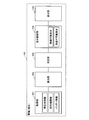
- FIG. 8 is a diagram illustrating a display example of a bar graph relating to cruising along with route guidance information.
- the route guidance information is displayed on the display unit 124 of the terminal 120 as a route searched by the terminal 120 or the server 100 based on the current location and destination information. In this case, for example, if the terminal 120 has a navigation function and has a route search and route guidance function, it is not necessary to transmit the route search and route guidance information to the server 100.
- the terminal 120 causes the display unit 124 to display the route search and route guidance information 800 generated inside the terminal 120.
- These pieces of information 800 include the current location 801, the distance 802 to the destination, the required time 803, the arrival time 804, the destination 805, the traveling direction 806 at the next intersection, and the traveling directions 807 at the subsequent intersections shown in FIG. Etc.
- the server 100 executes generation of the display signal related to the bar graph display described above, and the terminal 120 displays the display output from the server 100 as a bar graph 810 so as to be superimposed on a part of the information 800.
- the bar graph 810 can be viewed together with the route search and route guidance information 800.
- the bar graph 810 does not take up space in the lower part of the display area and can efficiently display a plurality of information in a small space, so that even if the display area of the display unit 124 is small, the bar graph 810 is visible. Can increase the sex.
- the bar graph 810 shown in FIG. 8 is displayed when cruising is possible, but is also displayed at the same location when cruising is impossible.
- FIG. 9 is a block diagram of a functional configuration of the display control system according to the second embodiment.
- the configuration example shown in FIG. 9 is a configuration in which the server 100 arranged in one place in the first embodiment is distributed to two servers A (901) and B (902).
- the server A (901) is provided for each region and exchanges information with the terminal 120.
- Server B (902) is provided, for example, at one location, accessed from a plurality of servers A (901), and performs processing specialized only for displaying bar graphs.
- the configuration of the terminal 120 is the same as that of the first embodiment (FIG. 1), and communicates with the server A (901).
- Server A (901) has a configuration of a calculation unit 102 and a determination unit 103.
- the receiving unit 101 and the transmitting unit 105 communicate with the terminal 120.
- the server B (902) has the configuration of the display control unit 104 as illustrated.
- the receiving unit 101 and the transmitting unit 105 communicate with the server A (901).
- the server A (901) and the server B (902) can also be configured by servers having different functions.
- FIG. 10 is a block diagram of a functional configuration of the display control system according to the third embodiment.
- the configurations of two servers A (901) and B (902) are the same as those in the second embodiment (FIG. 9).
- the configuration of terminal 120 is the same as in Embodiment 1 (FIG. 1) and Embodiment 2 (FIG. 9).
- the server A (901) has a configuration in which the reception unit 101 starts receiving information acquired by the acquisition unit 121 of the terminal 120, and includes a calculation unit 102 and a determination unit 103. Then, the transmission unit 105 outputs the determination result to the server B (902).
- the server B (902) receives the determination result of the server A (901) via the receiving unit 101 and has the configuration of the display control unit 104. Then, the display output is transmitted to the terminal 120 via the transmission unit 105.
- the terminal 120 receives the display output from the server B (902) by the receiving unit 123 and outputs the display output to the display unit 124.
- the information processed by the server A (901) may be output to the server B (902) and output from the server B (902) to the terminal 120. In this way, the server A (901) and the server B (902) can be configured and used as different functional servers.
- FIG. 11 is a block diagram of a functional configuration of the display control system according to the fourth embodiment.
- the terminal 120 includes an acquisition unit 121, a calculation unit 102, a determination unit 103, and a display unit 124.
- the transmission unit 122 transmits the determination result of the determination unit 103 to the server 100, and the reception unit 123 receives the display output of the display control unit 104 of the server 100 and displays it on the display unit 124.
- the reception unit 101 receives the determination result of the determination unit 103 of the terminal 120, the display control unit 104 generates a display output, and outputs the display output to the transmission unit 105.
- the transmission unit 105 transmits the display output to the terminal 120.
- the function of generating the display output can be configured to use the external server 100.
- FIG. 12 is a block diagram of a functional configuration of the display control apparatus according to the fifth embodiment.
- the terminal 120 has all functions without using an external server.
- the terminal 120 can be configured using, for example, a navigation device mounted on a mobile object. According to the fifth embodiment, all processing can be executed only by the terminal 120 in the mobile body without performing communication with an external server.
- FIG. 13 is a schematic diagram illustrating a functional configuration of each unit according to the sixth embodiment.
- two external servers A (1301) and server B (1302) are used for some processes.
- Server A (1301) performs processing specialized for route search and route guidance based on the current location and destination information. Then, the server A (1301) transmits link information between nodes on the route and battery information to the server B (1302). The server B (1302) performs power consumption (electricity cost prediction) necessary for the route to the destination based on the link information and the battery information.
- the server B (1302) is, for example, a Web API (Application Programming Interface), performs a process specialized only in the calculation of power consumption, and responds to the result of the power consumption prediction to the server A (1301). Then, the server A (1301) generates a bar graph to determine whether the vehicle can travel to the destination, and transmits it to the terminal 120.
- a Web API Application Programming Interface
- the configuration of the sixth embodiment is a configuration in which processing functions are shared using two separated servers as shown in the second embodiment (FIG. 9) or the third embodiment (FIG. 10). Equivalent to.
- the terminal 120 located in the mobile body has the functions of the acquisition unit 121, the transmission unit 122, the reception unit 123, and the display unit 124 described in the above-described embodiment.
- the server A (1301) has the functions of the reception unit 101, the calculation unit 102, the display control unit 104, and the transmission unit 105 described in the above embodiment.
- the calculation unit 102 calculates the link information described above, and the display control unit 104 generates a display output (display signal) for display control.
- the server B (1302) has the functions of the reception unit 101, the determination unit 103, and the transmission unit 105 described in the above embodiment.
- the determination unit 103 performs power consumption prediction processing and determines whether or not the destination can be reached.
- FIG. 14 is a flowchart of a process procedure according to the sixth embodiment.
- the processing performed at the mobile terminal 120, the processing performed at the server A (1301), and the processing performed at the server B (1302) are described.
- the terminal 120 executes the following processing until the end of travel after the movement of the vehicle (step S1401: No), and ends the processing when the travel ends (step S1401: Yes).
- step S1402 battery information is acquired by the acquisition unit 121 (step S1402).
- the acquisition unit 121 acquires current location information and destination information (step S1403).
- the acquired information is transmitted from the transmission unit to server A (1301) (step S1404).
- the terminal 120 acquires a display signal transmitted from the server A (1301) by the receiving unit (step S1405), and displays it on the display unit 124.
- step S1404 the server A (1301) searches for the route of the vehicle to the destination based on the battery information, the current location information, and the destination information transmitted from the terminal 120, and makes a traffic jam prediction on the route. (Step S1410). Thereafter, link data of a route to the destination is generated (step S1411) and transmitted to the server B (1302) (step S1411).
- the server A acquires the processing result of the power consumption prediction transmitted from the server B (1302), generates a display output based on the processing result of the power consumption prediction (step S1412), and transmits it to the terminal 120. (Step S1412).
- step S1420 based on the link data transmitted from the server A (1301), the power consumption to the destination of the moving object is predicted (step S1420), and the result of the power consumption prediction is the server A ( 1301) (step S1421).
- a plurality of servers A (1301) are installed for each region and the like, and exchange information with the terminals 120 in the region.
- One server B (1302) is provided with a function such as WebAPI, and exchanges information with a plurality of servers A (1301).
- the terminal 120 can obtain a necessary display output from the server A (1301) only by preparing an interface with the server A (1301) communicating with each other without being aware of the number of servers.
- the display control method described in this embodiment can be realized by executing a program prepared in advance on a computer such as a personal computer or a workstation.
- This program is recorded on a computer-readable recording medium such as a hard disk, a flexible disk, a CD-ROM, an MO, and a DVD, and is executed by being read from the recording medium by the computer.
- the program may be a transmission medium that can be distributed via a network such as the Internet.
Landscapes
- Engineering & Computer Science (AREA)
- Radar, Positioning & Navigation (AREA)
- Remote Sensing (AREA)
- Automation & Control Theory (AREA)
- Physics & Mathematics (AREA)
- General Physics & Mathematics (AREA)
- Life Sciences & Earth Sciences (AREA)
- Sustainable Development (AREA)
- Sustainable Energy (AREA)
- Power Engineering (AREA)
- Transportation (AREA)
- Mechanical Engineering (AREA)
- Navigation (AREA)
- Instrument Panels (AREA)
- Electric Propulsion And Braking For Vehicles (AREA)
Abstract
L'invention concerne un dispositif de commande d'affichage (100) qui génère un signal de commande d'affichage indiquant si un objet mobile peut continuer ou non son parcours jusqu'à une destination sur la base du niveau résiduel dans une batterie d'une source motrice dudit objet mobile, et qui comporte : une unité de calcul (102) qui calcule la quantité épuisée de la batterie à utiliser sur un parcours que l'objet emprunte pour arriver à la destination ; une unité de détermination (103) qui, sur la base du résultat du calcul effectué par l'unité de calcul (102), détermine si un objet mobile peut continuer ou non son parcours jusqu'à la destination ; et une unité de commande d'affichage (104) qui génère le signal de commande d'affichage qui, quand l'objet mobile peut continuer son parcours jusqu'à la destination, affiche le niveau résiduel dans la batterie, après que l'objet mobile continue son parcours jusqu'à la destination, avec une première forme d'affichage, et, quand l'objet mobile ne peut pas continuer son parcours jusqu'à la destination, affiche le niveau qui manque dans la batterie pour pouvoir poursuivre le parcours jusqu'à la destination, avec une deuxième forme d'affichage qui diffère visuellement de la première forme d'affichage.
Priority Applications (3)
| Application Number | Priority Date | Filing Date | Title |
|---|---|---|---|
| CN201180068824.7A CN103402807B (zh) | 2011-03-30 | 2011-03-30 | 显示控制装置、终端、显示控制系统以及显示控制方法 |
| PCT/JP2011/058147 WO2012131963A1 (fr) | 2011-03-30 | 2011-03-30 | Dispositif de commande d'affichage, terminal, système de commande d'affichage et procédé de commande d'affichage |
| JP2011538196A JP4886099B1 (ja) | 2011-03-30 | 2011-03-30 | 表示制御装置、端末、表示制御システムおよび表示制御方法 |
Applications Claiming Priority (1)
| Application Number | Priority Date | Filing Date | Title |
|---|---|---|---|
| PCT/JP2011/058147 WO2012131963A1 (fr) | 2011-03-30 | 2011-03-30 | Dispositif de commande d'affichage, terminal, système de commande d'affichage et procédé de commande d'affichage |
Publications (1)
| Publication Number | Publication Date |
|---|---|
| WO2012131963A1 true WO2012131963A1 (fr) | 2012-10-04 |
Family
ID=45851300
Family Applications (1)
| Application Number | Title | Priority Date | Filing Date |
|---|---|---|---|
| PCT/JP2011/058147 WO2012131963A1 (fr) | 2011-03-30 | 2011-03-30 | Dispositif de commande d'affichage, terminal, système de commande d'affichage et procédé de commande d'affichage |
Country Status (3)
| Country | Link |
|---|---|
| JP (1) | JP4886099B1 (fr) |
| CN (1) | CN103402807B (fr) |
| WO (1) | WO2012131963A1 (fr) |
Cited By (2)
| Publication number | Priority date | Publication date | Assignee | Title |
|---|---|---|---|---|
| WO2016056069A1 (fr) * | 2014-10-07 | 2016-04-14 | 日産自動車株式会社 | Appareil de calcul de plage et procédé de calcul de plage |
| FR3122279A1 (fr) * | 2021-04-23 | 2022-10-28 | Inlecom Innovation Astiki Mi Kerdoskopiki Etaireia | Planification dynamique de charge de véhicule électrique |
Families Citing this family (11)
| Publication number | Priority date | Publication date | Assignee | Title |
|---|---|---|---|---|
| JP5860136B2 (ja) * | 2012-03-28 | 2016-02-16 | パイオニア株式会社 | 画像処理装置、画像処理管理装置、端末装置及び画像処理方法 |
| JP5815843B2 (ja) * | 2012-03-30 | 2015-11-17 | パイオニア株式会社 | 画像処理装置、画像処理管理装置、端末装置及び画像処理方法 |
| JP5818971B2 (ja) * | 2012-03-30 | 2015-11-18 | パイオニア株式会社 | 探索装置、探索管理装置、端末装置及び算出方法 |
| WO2014049706A1 (fr) * | 2012-09-26 | 2014-04-03 | パイオニア株式会社 | Dispositif de commande d'affichage, procédé de commande d'affichage, programme et dispositif de serveur |
| WO2015011997A1 (fr) * | 2013-07-25 | 2015-01-29 | 日産自動車株式会社 | Système de guidage à prévision d'énergie restante |
| DE102014201863A1 (de) * | 2014-02-03 | 2015-08-06 | Volkswagen Aktiengesellschaft | Verfahren und Vorrichtung zum Anzeigen von Fahrzeugparametern |
| CN104460627B (zh) * | 2014-12-10 | 2017-03-08 | 国家电网公司 | 一种水电站水轮发电机组显控系统及其控制方法 |
| JP7067020B2 (ja) | 2017-11-02 | 2022-05-16 | トヨタ自動車株式会社 | 電気自動車 |
| CN108344424A (zh) * | 2018-03-06 | 2018-07-31 | 上海博泰悦臻网络技术服务有限公司 | 电动汽车及其导航方法和系统 |
| WO2019176114A1 (fr) | 2018-03-16 | 2019-09-19 | 本田技研工業株式会社 | Dispositif d'affichage |
| CN108556661B (zh) * | 2018-04-23 | 2021-10-22 | 山东理工大学 | 一种电动汽车主动充电预警及预约方法 |
Citations (5)
| Publication number | Priority date | Publication date | Assignee | Title |
|---|---|---|---|---|
| JP2003021522A (ja) * | 2001-07-09 | 2003-01-24 | Nissan Motor Co Ltd | 情報提示装置 |
| JP2004266898A (ja) * | 2003-02-28 | 2004-09-24 | Asti Corp | 車両制御装置 |
| JP2007116799A (ja) * | 2005-10-19 | 2007-05-10 | Leben Hanbai:Kk | バッテリー管理システム |
| JP2008100646A (ja) * | 2006-10-20 | 2008-05-01 | Toyota Motor Corp | ハイブリッド車両の制御装置 |
| JP2011075382A (ja) * | 2009-09-30 | 2011-04-14 | Clarion Co Ltd | ナビゲーション装置および経路演算方法 |
-
2011
- 2011-03-30 JP JP2011538196A patent/JP4886099B1/ja active Active
- 2011-03-30 WO PCT/JP2011/058147 patent/WO2012131963A1/fr active Application Filing
- 2011-03-30 CN CN201180068824.7A patent/CN103402807B/zh active Active
Patent Citations (5)
| Publication number | Priority date | Publication date | Assignee | Title |
|---|---|---|---|---|
| JP2003021522A (ja) * | 2001-07-09 | 2003-01-24 | Nissan Motor Co Ltd | 情報提示装置 |
| JP2004266898A (ja) * | 2003-02-28 | 2004-09-24 | Asti Corp | 車両制御装置 |
| JP2007116799A (ja) * | 2005-10-19 | 2007-05-10 | Leben Hanbai:Kk | バッテリー管理システム |
| JP2008100646A (ja) * | 2006-10-20 | 2008-05-01 | Toyota Motor Corp | ハイブリッド車両の制御装置 |
| JP2011075382A (ja) * | 2009-09-30 | 2011-04-14 | Clarion Co Ltd | ナビゲーション装置および経路演算方法 |
Cited By (2)
| Publication number | Priority date | Publication date | Assignee | Title |
|---|---|---|---|---|
| WO2016056069A1 (fr) * | 2014-10-07 | 2016-04-14 | 日産自動車株式会社 | Appareil de calcul de plage et procédé de calcul de plage |
| FR3122279A1 (fr) * | 2021-04-23 | 2022-10-28 | Inlecom Innovation Astiki Mi Kerdoskopiki Etaireia | Planification dynamique de charge de véhicule électrique |
Also Published As
| Publication number | Publication date |
|---|---|
| CN103402807B (zh) | 2016-06-08 |
| JPWO2012131963A1 (ja) | 2014-07-24 |
| CN103402807A (zh) | 2013-11-20 |
| JP4886099B1 (ja) | 2012-02-29 |
Similar Documents
| Publication | Publication Date | Title |
|---|---|---|
| JP4886099B1 (ja) | 表示制御装置、端末、表示制御システムおよび表示制御方法 | |
| EP2369298B1 (fr) | Dispositif de guidage de chargement de véhicule, procédé de guidage de chargement de véhicule et produit de programme informatique | |
| US10906424B2 (en) | System for announcing predicted remaining amount of energy | |
| US9835463B2 (en) | Route searching device, terminal device, and route searching method | |
| JP5787797B2 (ja) | 走行可能範囲算出装置、方法、およびプログラム | |
| US10866107B2 (en) | Navigation system | |
| JP5853499B2 (ja) | 走行可能領域表示装置 | |
| JP2013115873A (ja) | 車車間電力送受システム、車載電力送受制御装置 | |
| JP6025248B2 (ja) | 航続可能経路演算装置及びコンピュータプログラム | |
| JP2011203174A (ja) | 車両経路案内装置及び車両経路案内システム | |
| WO2014024604A1 (fr) | Dispositif de calcul d'itinéraire pouvant être parcouru, programme d'ordinateur et dispositif de génération de données d'affichage | |
| JP5433670B2 (ja) | 表示制御装置、表示制御方法およびサーバ | |
| CN109579862A (zh) | 电动汽车的导航方法、系统、设备以及介质 | |
| KR101886583B1 (ko) | 차량 시스템 및 차량 시스템의 내비게이션 경로 선택 방법 | |
| CN116343518A (zh) | 电动机动车辆的引导系统 | |
| JP2015001466A (ja) | 経路探索装置、端末装置及び経路探索方法 | |
| JP6021024B2 (ja) | 表示方法、表示装置、表示システム、及びコンピュータプログラム | |
| JP2014009948A (ja) | 経路情報提供システム、及び、ナビゲーション装置 | |
| JP2019158625A (ja) | 電子装置および走行可能エリアの表示方法 | |
| JP6089362B2 (ja) | 航続可能経路演算装置及びコンピュータプログラム | |
| JP7062749B2 (ja) | サーバ装置、その制御方法、およびプログラム | |
| WO2014080506A1 (fr) | Dispositif de commande d'affichage, méthode de commande d'affichage, programme de commande d'affichage, système de commande d'affichage, serveur de commande d'affichage et terminal | |
| WO2014068685A1 (fr) | Dispositif de commande d'affichage, dispositif de serveur, procédé de commande d'affichage, programme de commande d'affichage et support d'enregistrement | |
| JP2024090013A (ja) | 充電施設の案内優先度決定システム | |
| JP2023001521A (ja) | 車両および充電システム |
Legal Events
| Date | Code | Title | Description |
|---|---|---|---|
| ENP | Entry into the national phase |
Ref document number: 2011538196 Country of ref document: JP Kind code of ref document: A |
|
| 121 | Ep: the epo has been informed by wipo that ep was designated in this application |
Ref document number: 11862618 Country of ref document: EP Kind code of ref document: A1 |
|
| NENP | Non-entry into the national phase |
Ref country code: DE |
|
| 122 | Ep: pct application non-entry in european phase |
Ref document number: 11862618 Country of ref document: EP Kind code of ref document: A1 |