WO2012131963A1 - Display control device, terminal, display control system and display control method - Google Patents
Display control device, terminal, display control system and display control method Download PDFInfo
- Publication number
- WO2012131963A1 WO2012131963A1 PCT/JP2011/058147 JP2011058147W WO2012131963A1 WO 2012131963 A1 WO2012131963 A1 WO 2012131963A1 JP 2011058147 W JP2011058147 W JP 2011058147W WO 2012131963 A1 WO2012131963 A1 WO 2012131963A1
- Authority
- WO
- WIPO (PCT)
- Prior art keywords
- destination
- display control
- battery
- display
- continue
- Prior art date
Links
Images


Classifications
-
- G—PHYSICS
- G01—MEASURING; TESTING
- G01C—MEASURING DISTANCES, LEVELS OR BEARINGS; SURVEYING; NAVIGATION; GYROSCOPIC INSTRUMENTS; PHOTOGRAMMETRY OR VIDEOGRAMMETRY
- G01C21/00—Navigation; Navigational instruments not provided for in groups G01C1/00 - G01C19/00
- G01C21/26—Navigation; Navigational instruments not provided for in groups G01C1/00 - G01C19/00 specially adapted for navigation in a road network
- G01C21/34—Route searching; Route guidance
- G01C21/3453—Special cost functions, i.e. other than distance or default speed limit of road segments
- G01C21/3469—Fuel consumption; Energy use; Emission aspects
-
- B—PERFORMING OPERATIONS; TRANSPORTING
- B60—VEHICLES IN GENERAL
- B60L—PROPULSION OF ELECTRICALLY-PROPELLED VEHICLES; SUPPLYING ELECTRIC POWER FOR AUXILIARY EQUIPMENT OF ELECTRICALLY-PROPELLED VEHICLES; ELECTRODYNAMIC BRAKE SYSTEMS FOR VEHICLES IN GENERAL; MAGNETIC SUSPENSION OR LEVITATION FOR VEHICLES; MONITORING OPERATING VARIABLES OF ELECTRICALLY-PROPELLED VEHICLES; ELECTRIC SAFETY DEVICES FOR ELECTRICALLY-PROPELLED VEHICLES
- B60L58/00—Methods or circuit arrangements for monitoring or controlling batteries or fuel cells, specially adapted for electric vehicles
- B60L58/10—Methods or circuit arrangements for monitoring or controlling batteries or fuel cells, specially adapted for electric vehicles for monitoring or controlling batteries
- B60L58/12—Methods or circuit arrangements for monitoring or controlling batteries or fuel cells, specially adapted for electric vehicles for monitoring or controlling batteries responding to state of charge [SoC]
-
- B—PERFORMING OPERATIONS; TRANSPORTING
- B60—VEHICLES IN GENERAL
- B60L—PROPULSION OF ELECTRICALLY-PROPELLED VEHICLES; SUPPLYING ELECTRIC POWER FOR AUXILIARY EQUIPMENT OF ELECTRICALLY-PROPELLED VEHICLES; ELECTRODYNAMIC BRAKE SYSTEMS FOR VEHICLES IN GENERAL; MAGNETIC SUSPENSION OR LEVITATION FOR VEHICLES; MONITORING OPERATING VARIABLES OF ELECTRICALLY-PROPELLED VEHICLES; ELECTRIC SAFETY DEVICES FOR ELECTRICALLY-PROPELLED VEHICLES
- B60L2240/00—Control parameters of input or output; Target parameters
- B60L2240/40—Drive Train control parameters
- B60L2240/54—Drive Train control parameters related to batteries
- B60L2240/547—Voltage
-
- B—PERFORMING OPERATIONS; TRANSPORTING
- B60—VEHICLES IN GENERAL
- B60L—PROPULSION OF ELECTRICALLY-PROPELLED VEHICLES; SUPPLYING ELECTRIC POWER FOR AUXILIARY EQUIPMENT OF ELECTRICALLY-PROPELLED VEHICLES; ELECTRODYNAMIC BRAKE SYSTEMS FOR VEHICLES IN GENERAL; MAGNETIC SUSPENSION OR LEVITATION FOR VEHICLES; MONITORING OPERATING VARIABLES OF ELECTRICALLY-PROPELLED VEHICLES; ELECTRIC SAFETY DEVICES FOR ELECTRICALLY-PROPELLED VEHICLES
- B60L2240/00—Control parameters of input or output; Target parameters
- B60L2240/40—Drive Train control parameters
- B60L2240/54—Drive Train control parameters related to batteries
- B60L2240/549—Current
-
- B—PERFORMING OPERATIONS; TRANSPORTING
- B60—VEHICLES IN GENERAL
- B60L—PROPULSION OF ELECTRICALLY-PROPELLED VEHICLES; SUPPLYING ELECTRIC POWER FOR AUXILIARY EQUIPMENT OF ELECTRICALLY-PROPELLED VEHICLES; ELECTRODYNAMIC BRAKE SYSTEMS FOR VEHICLES IN GENERAL; MAGNETIC SUSPENSION OR LEVITATION FOR VEHICLES; MONITORING OPERATING VARIABLES OF ELECTRICALLY-PROPELLED VEHICLES; ELECTRIC SAFETY DEVICES FOR ELECTRICALLY-PROPELLED VEHICLES
- B60L2240/00—Control parameters of input or output; Target parameters
- B60L2240/60—Navigation input
- B60L2240/62—Vehicle position
-
- B—PERFORMING OPERATIONS; TRANSPORTING
- B60—VEHICLES IN GENERAL
- B60L—PROPULSION OF ELECTRICALLY-PROPELLED VEHICLES; SUPPLYING ELECTRIC POWER FOR AUXILIARY EQUIPMENT OF ELECTRICALLY-PROPELLED VEHICLES; ELECTRODYNAMIC BRAKE SYSTEMS FOR VEHICLES IN GENERAL; MAGNETIC SUSPENSION OR LEVITATION FOR VEHICLES; MONITORING OPERATING VARIABLES OF ELECTRICALLY-PROPELLED VEHICLES; ELECTRIC SAFETY DEVICES FOR ELECTRICALLY-PROPELLED VEHICLES
- B60L2250/00—Driver interactions
- B60L2250/16—Driver interactions by display
-
- B—PERFORMING OPERATIONS; TRANSPORTING
- B60—VEHICLES IN GENERAL
- B60L—PROPULSION OF ELECTRICALLY-PROPELLED VEHICLES; SUPPLYING ELECTRIC POWER FOR AUXILIARY EQUIPMENT OF ELECTRICALLY-PROPELLED VEHICLES; ELECTRODYNAMIC BRAKE SYSTEMS FOR VEHICLES IN GENERAL; MAGNETIC SUSPENSION OR LEVITATION FOR VEHICLES; MONITORING OPERATING VARIABLES OF ELECTRICALLY-PROPELLED VEHICLES; ELECTRIC SAFETY DEVICES FOR ELECTRICALLY-PROPELLED VEHICLES
- B60L2260/00—Operating Modes
- B60L2260/40—Control modes
- B60L2260/50—Control modes by future state prediction
- B60L2260/52—Control modes by future state prediction drive range estimation, e.g. of estimation of available travel distance
-
- Y—GENERAL TAGGING OF NEW TECHNOLOGICAL DEVELOPMENTS; GENERAL TAGGING OF CROSS-SECTIONAL TECHNOLOGIES SPANNING OVER SEVERAL SECTIONS OF THE IPC; TECHNICAL SUBJECTS COVERED BY FORMER USPC CROSS-REFERENCE ART COLLECTIONS [XRACs] AND DIGESTS
- Y02—TECHNOLOGIES OR APPLICATIONS FOR MITIGATION OR ADAPTATION AGAINST CLIMATE CHANGE
- Y02T—CLIMATE CHANGE MITIGATION TECHNOLOGIES RELATED TO TRANSPORTATION
- Y02T10/00—Road transport of goods or passengers
- Y02T10/60—Other road transportation technologies with climate change mitigation effect
- Y02T10/70—Energy storage systems for electromobility, e.g. batteries
-
- Y—GENERAL TAGGING OF NEW TECHNOLOGICAL DEVELOPMENTS; GENERAL TAGGING OF CROSS-SECTIONAL TECHNOLOGIES SPANNING OVER SEVERAL SECTIONS OF THE IPC; TECHNICAL SUBJECTS COVERED BY FORMER USPC CROSS-REFERENCE ART COLLECTIONS [XRACs] AND DIGESTS
- Y02—TECHNOLOGIES OR APPLICATIONS FOR MITIGATION OR ADAPTATION AGAINST CLIMATE CHANGE
- Y02T—CLIMATE CHANGE MITIGATION TECHNOLOGIES RELATED TO TRANSPORTATION
- Y02T10/00—Road transport of goods or passengers
- Y02T10/60—Other road transportation technologies with climate change mitigation effect
- Y02T10/72—Electric energy management in electromobility
-
- Y—GENERAL TAGGING OF NEW TECHNOLOGICAL DEVELOPMENTS; GENERAL TAGGING OF CROSS-SECTIONAL TECHNOLOGIES SPANNING OVER SEVERAL SECTIONS OF THE IPC; TECHNICAL SUBJECTS COVERED BY FORMER USPC CROSS-REFERENCE ART COLLECTIONS [XRACs] AND DIGESTS
- Y02—TECHNOLOGIES OR APPLICATIONS FOR MITIGATION OR ADAPTATION AGAINST CLIMATE CHANGE
- Y02T—CLIMATE CHANGE MITIGATION TECHNOLOGIES RELATED TO TRANSPORTATION
- Y02T90/00—Enabling technologies or technologies with a potential or indirect contribution to GHG emissions mitigation
- Y02T90/10—Technologies relating to charging of electric vehicles
- Y02T90/16—Information or communication technologies improving the operation of electric vehicles
Definitions
- the present invention relates to a display control device, a terminal, a display control system, and a display control method for displaying a cruising state depending on a remaining battery level of an electric vehicle.
- utilization of this invention is not restricted to a display control apparatus, a terminal, a display control system, and a display control method.
- the distance to the destination and the travelable distance are displayed on the numbers and the map, but it is not known how much the battery is insufficient to reach the destination at the current location. . Further, since it is not known how much the battery can be charged, for example, it cannot be determined whether the battery can be reached at the current location by charging the battery.
- the display control device is based on the remaining amount of the battery of the driving source of the moving body, and whether the moving body can continue to the destination.
- a display control device that generates a display control signal for displaying whether or not, a calculation unit that calculates a consumption amount of the battery that is consumed in a route that the moving body moves to the destination, and a calculation result of the calculation unit
- a determination unit that determines whether or not the moving body can continue to the destination; and when the moving body can continue to the destination, the remaining amount of the battery after traveling to the destination
- the mobile body cannot display the first display form and the mobile body cannot continue to the destination the shortage of the battery necessary to continue to the destination is visually recognized as the first display form.
- Different second display Characterized in that it comprises a display control unit that generates a first display control signal for displaying at state, a.
- a display control device for displaying a display control signal for displaying whether or not the moving body can continue to a destination based on a remaining battery level of a driving source of the moving body.
- the remaining amount of the battery after traveling to the destination is displayed on the display unit in a first display form, and the mobile body Is not able to continue to the destination, the battery shortage necessary to continue to the destination is displayed on the display unit in a second display form visually different from the first display form.
- a display control unit for displaying is provided.
- a display control signal for displaying whether or not the moving body can continue to a destination based on a terminal and a remaining amount of a battery of a driving source of the moving body.
- the terminal transmits the information on the battery of the driving source of the moving body to the display control device, and acquires the information on the battery.
- a first communication unit that receives the display control signal from a device; and a display unit that outputs a display based on the display control signal.
- the display control device is consumed by a route along which the moving body moves to the destination.
- a calculation unit for calculating the consumption amount of the battery a determination unit for determining whether or not the mobile unit can continue to the destination based on a calculation result of the calculation unit, and the mobile unit
- the remaining amount of the battery after continuing to the destination is displayed on the display unit in the first display form, and the mobile body cannot continue to the destination.
- a display control device for generating a display control signal for displaying whether or not the moving body can continue to a destination based on a remaining battery level of a driving source of the moving body.
- the display control apparatus when the mobile body can travel to the destination based on the consumption amount of the battery consumed by the mobile body on the route to the destination, after the mobile body has traveled to the destination, When the remaining amount of the battery is displayed in the first display form, and the mobile body cannot continue to the destination, the shortage of the battery necessary to continue to the destination is
- generates the display control signal displayed with the 2nd display form visually different from this display form is characterized by the above-mentioned.
- the display control method generates a display control signal for displaying whether or not the moving body can travel to the destination based on the remaining battery level of the driving source of the moving body.
- the display control method of the display control device based on a calculation step of calculating a consumption amount of the battery consumed by a route along which the moving body moves to the destination, and based on a calculation result of the calculating step, the moving body is set to the target A determination step for determining whether or not it is possible to continue to the ground; and when the moving body can continue to the destination, the remaining amount of the battery after traveling to the destination is displayed in a first display form. And when the moving body is unable to continue to the destination, a second display form visually different from the first display form indicates a shortage of the battery required to continue to the destination. Display with Characterized by comprising a display control step of generating ⁇ control signal.
- the display control method generates a display control signal for displaying whether or not the moving body can travel to the destination based on the remaining battery level of the driving source of the moving body.
- the display control method of the display control device when the mobile body can travel to the destination based on the consumption amount of the battery consumed on the route that the mobile body moves to the destination, The remaining amount of the battery after cruising is displayed in the first display form, and when the mobile body cannot continue to the destination, the shortage of the battery necessary to continue to the destination Including a display control step of generating a display control signal for displaying the image in a second display form visually different from the first display form.
- the display control device generates a display control signal for displaying whether or not the moving body can continue to the destination based on the remaining battery level of the driving source of the moving body.
- the mobile unit can travel to the destination based on a calculation unit that calculates a consumption amount of the battery that is consumed on a route along which the mobile unit moves to the destination, and a calculation result of the calculation unit.
- FIG. 1 is a block diagram of a functional configuration of the display control system according to the first embodiment.
- FIG. 2 is a flowchart showing a procedure of display control processing by the display control system.
- FIG. 3 is a block diagram illustrating a hardware configuration of the server.
- FIG. 4 is a diagram illustrating a display example when cruising is possible.
- FIG. 5 is a diagram illustrating a display example when cruising is impossible.
- FIG. 6 is a diagram illustrating a display example when cruising is possible when a destination is not set.
- FIG. 7 is a diagram illustrating a display example when cruising is impossible.
- FIG. 8 is a diagram illustrating a display example of a bar graph relating to cruising along with route guidance information.
- FIG. 1 is a block diagram of a functional configuration of the display control system according to the first embodiment.
- FIG. 2 is a flowchart showing a procedure of display control processing by the display control system.
- FIG. 3 is a block diagram illustrating
- FIG. 9 is a block diagram of a functional configuration of the display control system according to the second embodiment.
- FIG. 10 is a block diagram of a functional configuration of the display control system according to the third embodiment.
- FIG. 11 is a block diagram of a functional configuration of the display control system according to the fourth embodiment.
- FIG. 12 is a block diagram of a functional configuration of the display control apparatus according to the fifth embodiment.
- FIG. 13 is a schematic diagram illustrating a functional configuration of each unit according to the sixth embodiment.
- FIG. 14 is a flowchart of a process procedure according to the sixth embodiment.
- FIG. 1 is a block diagram of a functional configuration of the display control system according to the first embodiment.
- a mobile body vehicle
- a terminal 120 exchanges information with a server 100 provided outside the mobile body (terminal) 120 by communication.
- the server 100 includes a receiving unit 101, a calculating unit 102, a determining unit 103, a display control unit 104, and a transmitting unit 105. Further, the terminal 120 includes an acquisition unit 121, a transmission unit 122, a reception unit 123, and a display unit 124.
- the acquisition unit 121 of the terminal 120 acquires current location information, destination information, and battery information.
- the current location information and the destination information are each location information, for example, latitude and longitude, and are acquired by GPS or the like.
- the battery information detects the maximum charge capacity of the battery of the mobile unit and the current remaining battery level.
- CAN in-vehicle communication network
- ECU electronice control unit
- the transmission unit 122 transmits the current location information, destination information, and battery information acquired by the acquisition unit 121 to the server 100 via the communication network 131.
- the receiving unit 123 receives battery running information from the server 100 via the communication network 131.
- the battery driving information is whether or not it is possible to continue to the destination with the current remaining battery level, the remaining battery level when it is possible to continue, or the insufficient battery level when it is impossible to continue, etc. Consists of information.
- the battery running information received via the receiving unit 123 is displayed on the display unit 124, and the user can continue to the destination according to the displayed content, and the remaining battery level when the user can continue traveling, or When cruising is impossible, the amount of battery shortage and other information can be obtained.
- the server receiving unit 101 receives the current location information, the destination information, and the battery information transmitted from the transmitting unit 122 of the terminal 120, and outputs them to the calculating unit 102. Based on the current location information, the destination information, and the battery information, the calculation unit 102 calculates a cruising distance with the current remaining battery level. At this time, the calculation unit 102 uses the map information to search for a plurality of routes in a range that can be navigated from the current location to the destination direction.
- the determination unit 103 determines whether the cruising distance calculated by the calculation unit 102 reaches the destination. As a result of the determination, when the cruising distance reaches the destination, the battery amount consumed up to the destination and the remaining battery level after reaching the destination are output together. If the cruising distance cannot reach the destination, the point when the battery is completely consumed and the shortage of battery from this point to the destination are output together.
- the display control unit 104 outputs a display signal to be displayed with different display contents depending on whether the reachable distance reaches the destination as a result of the determination by the determination unit 103. If it is reachable, a bar graph is displayed to show that it is reachable at a glance. At this time, the bar graph outputs a display signal divided by the amount of battery consumed up to the destination and the remaining amount of the battery after reaching the destination.
- the bar graph outputs a display signal in which the point when the battery is completely consumed and the insufficient amount of battery from this point to the destination are separated.
- the transmission unit 105 transmits the display signal output from the display control unit 104 to the terminal 120.
- the terminal 120 can receive a display signal whose display is controlled on the server 100 side, and display and output it on the display unit 124.
- FIG. 2 is a flowchart showing a procedure of display control processing by the display control system.
- the acquisition unit 121 of the terminal 120 acquires current location information and destination information set in the vehicle (step S201).
- vehicle battery information is acquired (step S202). This battery information is the maximum charge capacity of the battery and the current remaining battery level.
- the information acquired in step S201 and step S202 is transmitted from the transmission unit 122 of the terminal 120 to the server 100 via the communication network 131.
- the receiving unit 101 of the server 100 receives information transmitted from the terminal 120.
- the calculation unit 102 calculates a cruising range based on the received current location information, destination information, and battery information (step S203).
- the calculation unit 102 searches for a route to the destination of the moving object based on the link information included in the acquired map data.
- a link is a section divided by points where road types and speed bands change, points where regions change such as boundaries of prefectures and municipalities, and the like.
- Link information is set for each link.
- the link information includes the link position and altitude, the link distance, the moving time of the moving object, and the like.
- the calculation unit 102 searches for a plurality of one route formed by connecting adjacent links from the departure point of the moving body to the destination by variously changing the link connection.
- the link information of each link may be used as a weight during route search. It is possible to perform route search with priority on time, distance, and energy consumption according to weighting.
- the route search condition when the route search condition is time-prioritized, one route configured by connecting the links that can be moved in the shortest time is searched.
- the link cost from the starting point of the moving object to the destination is integrated for each link information.
- the route search is performed using the link information in each link as the link cost.
- the weight of each link information may be changed according to the integrated cost of each link information.
- the determination unit 103 determines whether the cruising distance calculated by the calculation unit 102 is cruising to the destination (step S204). If the result of determination by the determination unit 103 is that it is possible to continue to the destination (step S204: Yes), the display control unit 104 performs display output indicating that it can be reached (first display form). Further, the battery amount consumed up to the destination and the remaining amount of the battery after reaching the destination are output together (step S205), and the series of processes is terminated.
- step S204 determines whether the result of determination by the determination unit 103 is that it is not possible to continue to the destination. If the result of determination by the determination unit 103 is that it is not possible to continue to the destination (step S204: No), the display control unit 104 performs display output indicating that the destination cannot be reached (second display mode) ). Further, the point when the battery is completely consumed and the insufficient amount of battery from this point to the destination are output together (step S206), and the series of processing ends.
- the display output by the display control unit 104 is received by the reception unit 123 of the terminal 120 via the transmission unit 105, displayed on the display unit 124, and notified to the user.
- the display control system determines whether or not the moving body can continue to the destination with the current battery, and the display content varies depending on whether or not the mobile body can continue. Is displayed to the user, the user can intuitively determine whether or not it is possible to continue to the destination. In addition, if the cruising is possible, the remaining battery level is displayed together, so that it is possible to travel while recognizing a sufficient state in advance. If the cruising is impossible, it is displayed how much the battery is insufficient, and thus it is possible to navigate considering the shortage of the battery.
- FIG. 3 is a block diagram illustrating a hardware configuration of the server.
- the server 100 includes a CPU 301, ROM 302, RAM 303, magnetic disk drive 304, magnetic disk 305, optical disk drive 306, optical disk 307, input device 311, and communication I / F 315.
- Each component 301 to 315 is connected by a bus 320.
- the CPU 301 governs overall control of the server 100.
- the ROM 302 records programs such as the display control described above.
- the RAM 303 is used as a work area for the CPU 301. That is, the CPU 301 controls the entire server 100 by executing various programs recorded in the ROM 302 while using the RAM 303 as a work area.
- the magnetic disk drive 304 controls the reading / writing of the data with respect to the magnetic disk 305 according to control of CPU301.
- the magnetic disk 305 records data written under the control of the magnetic disk drive 304.
- an HD hard disk
- FD flexible disk
- the optical disk drive 306 controls reading / writing of data with respect to the optical disk 307 according to the control of the CPU 301.
- the optical disk 307 is a detachable recording medium from which data is read according to the control of the optical disk drive 306.
- a writable recording medium can be used as the optical disc 307.
- an MO, a memory card, or the like can be used as a removable recording medium.
- Examples of information recorded on the magnetic disk 305 and the optical disk 307 include map data, and link information such as position information and altitude at each link.
- Map data is used for route search processing and route guidance processing, and includes background data that represents features (features) such as buildings, rivers, and the ground surface, and road shape data that represents road shapes with links and nodes. Yes.
- the input device 311 includes a remote controller, a keyboard, a touch panel, and the like provided with a plurality of keys for inputting characters, numerical values, various instructions, and the like.
- the input device 311 may be realized by any one form of a remote control, a keyboard, and a touch panel, but can also be realized by a plurality of forms.
- the communication I / F 315 is connected to a network via a wire or wirelessly, and functions as an interface between the server 100 and the CPU 301.
- the communication network functioning as a network includes a public line network, a mobile phone network, DSRC (Dedicated Short Range Communication), LAN, WAN, and the like.
- the communication I / F 315 is, for example, a public line connection module.
- the acquisition unit 121, the calculation unit 102, the determination unit 103, and the display control unit 104 illustrated in FIG. 1 are set by the CPU 301 using predetermined programs and data recorded in the ROM 302, the RAM 303, the magnetic disk 305, the optical disk 307, and the like.
- the function is realized by executing the program.
- the hardware configuration of the terminal 120 includes a CPU, a ROM, and a RAM.
- the CPU uses various programs recorded in the ROM while using the RAM as a work area. By executing this, the entire terminal 120 is controlled.
- the terminal 120 has GPS function as various sensors, and can acquire the current location and location information of the destination. If the terminal 120 is configured to have a map function, the location information of the destination can be easily acquired by displaying the vicinity of the destination on the map. Moreover, as various sensors, the maximum charge capacity of the battery of the moving body and the current battery remaining amount are acquired. In addition, a communication I / F is provided to exchange information with the external server 100 by communication.
- the terminal 120 includes an input device, and various operation inputs are possible.
- various types of information can be acquired by providing a magnetic disk drive, a magnetic disk, an optical disk drive, an optical disk, and the like.
- FIG. 4 is a diagram illustrating a display example when cruising is possible.
- the display control unit 104 shows a display example in the case where it is possible to continue to the destination.
- a display output indicating that it is reachable is made on the display unit 124 of the terminal 120.
- this display is displayed as a bar graph (bar graph or dot).
- the length of the bar graph is displayed as the maximum charge capacity L1 of the battery.
- the current charging capacity L2 is displayed with a predetermined length from one end (the left end in the figure). The left end of the figure corresponds to the current location a. It is possible to know how much the battery can be charged by the current charge capacity L2 with respect to the maximum charge capacity L1.
- the expected battery consumption L3 consumed for navigation to the destination b is displayed in a predetermined length from the current location a to the destination b. From the position of the destination b, the remaining amount L4 of the battery is displayed in a predetermined length between the travelable distance d. Since the display shown in FIG. 4 is a display example when the cruising to the destination is possible, the predicted consumption L3 displayed as a bar graph and the remaining battery charge L4 can both be crushed to the destination b. For example, a color indicating that there is a safe cruising, such as light blue for the predicted consumption L3 and green for the remaining battery charge L4, is displayed.
- FIG. 5 is a diagram showing a display example when cruising is impossible. As a result of the determination by the determination unit 103, a display example when it is not possible to continue to the destination is shown. In this case, a display output indicating that the terminal 120 cannot be reached is output on the display unit 124 of the terminal 120.
- the length of the bar graph is the maximum charge capacity L1 of the battery.
- the current charging capacity L2 is displayed with a predetermined length from one end (the left end in the figure). The left end of the figure corresponds to the current location a. Further, the other end (right end in the figure) of the current charging capacity L2 is the travelable distance d. It is possible to know how much the battery can be charged by the current charge capacity L2 with respect to the maximum charge capacity L1.
- the section from the current charging capacity L2 (travelable distance d) to the destination (right side) destination b is displayed with a predetermined length as being a battery shortage L5.
- the current charging capacity L2 displayed as a bar graph is displayed using a color indicating that safe cruising is possible, such as light blue.
- the battery shortage L5 is insufficient for navigation to the destination b. It is displayed using a conspicuous color that can easily indicate that it is present.
- the user can immediately grasp and recognize that it is impossible to continue to the destination b with the current charging capacity L2 by the displayed color.
- the user can depart in a state where the user knows in advance that the battery needs to be charged during cruising to the destination.
- the above is the image display based on the first display control signal.
- the point e in the figure indicates the location of the charging station, which is a replenishing device for replenishing the battery.
- the location of the charging station is acquired based on the map information referred to by the supplementary position acquisition means when searching for a route from the current location to the destination.
- the server 100 displays the acquired location of the charging station corresponding to the distance of the section from the current location a to the destination b on the bar graph. This image is displayed based on the second display control signal generated together with the first display control signal described above.
- the user can obtain information on the position e of the charging station, know that the cruising to the destination b is possible, and can start with peace of mind.
- the position e of the charging station is displayed only in the area of the current charging capacity L2. According to this display, it becomes possible to prompt charging at a charging stand that can be charged with the current remaining battery level. Even if the current charging capacity L2 is extended by charging at the charging station, the position e of the charging station within the range of the bar of the current charging capacity L2 up to the destination b is displayed. As a result, the position e of the charging station can always be grasped, information relating to the charging after the next time can be obtained, and the destination b can be traveled with peace of mind.
- FIG. 6 is a diagram illustrating a display example when cruising is possible when a destination is not set.
- the calculation unit 102 sets the home position as the destination, and the determination unit 103 determines whether or not it is possible to continue to this home position. For this reason, when the destination cannot be acquired, the calculation unit 102 requests the acquisition unit 121 to set and receive the home position.
- the home position is a place where the mobile body returns such as a garage at home, and the latitude and longitude of the home position may be set in advance in the terminal 120.
- the length of the bar graph is displayed as the maximum charge capacity L1 of the battery, and the current charge capacity L2 is displayed with a predetermined length from one end (the left end in the figure). The left end of the figure corresponds to the current location a. It is possible to know how much the battery can be charged by the current charge capacity L2 with respect to the maximum charge capacity L1.
- the expected battery consumption L3 consumed for navigation to the home position c is displayed in a predetermined length from the current location a to the home position c.
- the remaining amount L4 of the battery is displayed in a predetermined length up to the travelable distance d. Since the display shown in FIG. 6 is a display example when the cruising to the destination is possible, both the expected consumption L3 displayed as a bar graph and the remaining battery charge L4 can be crushed to the home position c. For example, a color indicating that there is a safe cruising, such as light blue for the predicted consumption L3 and green for the remaining battery charge L4, is displayed.
- the home position c is set as the destination, so that the user is displayed that the current charging capacity L2 can continue to the home position c.
- the home position c usually has a charging facility and can be charged at the home position c.
- FIG. 7 is a diagram showing a display example when cruising is impossible. As a result of the determination by the determination unit 103, a display example when it is impossible to continue to the home position is shown. In this case, a display output indicating that the terminal 120 cannot be reached is output on the display unit 124 of the terminal 120.
- the length of the bar graph is the maximum charge capacity L1 of the battery.
- the current charging capacity L2 is displayed with a predetermined length from one end (the left end in the figure). The left end of the figure corresponds to the current location a. Further, the other end (right end in the figure) of the current charging capacity L2 is the travelable distance d. It is possible to know how much the battery can be charged by the current charge capacity L2 with respect to the maximum charge capacity L1.
- the section from the current charging capacity L2 (travelable distance d) to the previous (right side) home position c is displayed with a predetermined length as the battery shortage L5.
- the current charge capacity L2 displayed as a bar graph is displayed using a color indicating that safe cruising is possible, such as light blue.
- the battery shortage L5 is insufficient for navigation to the home position c. It is displayed using a color that easily informs you.
- the user can immediately grasp and recognize from the displayed color that it is impossible to continue to the home position c with the current charging capacity L2.
- the user can depart in a state where the user knows in advance that the battery needs to be charged during cruising to the destination.
- the point e in the figure indicates the location of the charging station as a point.
- the location of the charging station is displayed in correspondence with the distance of the section from the current location a to the home position c on the bar graph.
- the user can obtain information on the position e of the charging station, know that the cruising to the home position c is possible, and can start with peace of mind.
- the current charge capacity L2 region it is possible to travel safely to the home position c by the displayed position e of the charging stand.
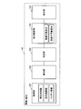
- FIG. 8 is a diagram illustrating a display example of a bar graph relating to cruising along with route guidance information.
- the route guidance information is displayed on the display unit 124 of the terminal 120 as a route searched by the terminal 120 or the server 100 based on the current location and destination information. In this case, for example, if the terminal 120 has a navigation function and has a route search and route guidance function, it is not necessary to transmit the route search and route guidance information to the server 100.
- the terminal 120 causes the display unit 124 to display the route search and route guidance information 800 generated inside the terminal 120.
- These pieces of information 800 include the current location 801, the distance 802 to the destination, the required time 803, the arrival time 804, the destination 805, the traveling direction 806 at the next intersection, and the traveling directions 807 at the subsequent intersections shown in FIG. Etc.
- the server 100 executes generation of the display signal related to the bar graph display described above, and the terminal 120 displays the display output from the server 100 as a bar graph 810 so as to be superimposed on a part of the information 800.
- the bar graph 810 can be viewed together with the route search and route guidance information 800.
- the bar graph 810 does not take up space in the lower part of the display area and can efficiently display a plurality of information in a small space, so that even if the display area of the display unit 124 is small, the bar graph 810 is visible. Can increase the sex.
- the bar graph 810 shown in FIG. 8 is displayed when cruising is possible, but is also displayed at the same location when cruising is impossible.
- FIG. 9 is a block diagram of a functional configuration of the display control system according to the second embodiment.
- the configuration example shown in FIG. 9 is a configuration in which the server 100 arranged in one place in the first embodiment is distributed to two servers A (901) and B (902).
- the server A (901) is provided for each region and exchanges information with the terminal 120.
- Server B (902) is provided, for example, at one location, accessed from a plurality of servers A (901), and performs processing specialized only for displaying bar graphs.
- the configuration of the terminal 120 is the same as that of the first embodiment (FIG. 1), and communicates with the server A (901).
- Server A (901) has a configuration of a calculation unit 102 and a determination unit 103.
- the receiving unit 101 and the transmitting unit 105 communicate with the terminal 120.
- the server B (902) has the configuration of the display control unit 104 as illustrated.
- the receiving unit 101 and the transmitting unit 105 communicate with the server A (901).
- the server A (901) and the server B (902) can also be configured by servers having different functions.
- FIG. 10 is a block diagram of a functional configuration of the display control system according to the third embodiment.
- the configurations of two servers A (901) and B (902) are the same as those in the second embodiment (FIG. 9).
- the configuration of terminal 120 is the same as in Embodiment 1 (FIG. 1) and Embodiment 2 (FIG. 9).
- the server A (901) has a configuration in which the reception unit 101 starts receiving information acquired by the acquisition unit 121 of the terminal 120, and includes a calculation unit 102 and a determination unit 103. Then, the transmission unit 105 outputs the determination result to the server B (902).
- the server B (902) receives the determination result of the server A (901) via the receiving unit 101 and has the configuration of the display control unit 104. Then, the display output is transmitted to the terminal 120 via the transmission unit 105.
- the terminal 120 receives the display output from the server B (902) by the receiving unit 123 and outputs the display output to the display unit 124.
- the information processed by the server A (901) may be output to the server B (902) and output from the server B (902) to the terminal 120. In this way, the server A (901) and the server B (902) can be configured and used as different functional servers.
- FIG. 11 is a block diagram of a functional configuration of the display control system according to the fourth embodiment.
- the terminal 120 includes an acquisition unit 121, a calculation unit 102, a determination unit 103, and a display unit 124.
- the transmission unit 122 transmits the determination result of the determination unit 103 to the server 100, and the reception unit 123 receives the display output of the display control unit 104 of the server 100 and displays it on the display unit 124.
- the reception unit 101 receives the determination result of the determination unit 103 of the terminal 120, the display control unit 104 generates a display output, and outputs the display output to the transmission unit 105.
- the transmission unit 105 transmits the display output to the terminal 120.
- the function of generating the display output can be configured to use the external server 100.
- FIG. 12 is a block diagram of a functional configuration of the display control apparatus according to the fifth embodiment.
- the terminal 120 has all functions without using an external server.
- the terminal 120 can be configured using, for example, a navigation device mounted on a mobile object. According to the fifth embodiment, all processing can be executed only by the terminal 120 in the mobile body without performing communication with an external server.
- FIG. 13 is a schematic diagram illustrating a functional configuration of each unit according to the sixth embodiment.
- two external servers A (1301) and server B (1302) are used for some processes.
- Server A (1301) performs processing specialized for route search and route guidance based on the current location and destination information. Then, the server A (1301) transmits link information between nodes on the route and battery information to the server B (1302). The server B (1302) performs power consumption (electricity cost prediction) necessary for the route to the destination based on the link information and the battery information.
- the server B (1302) is, for example, a Web API (Application Programming Interface), performs a process specialized only in the calculation of power consumption, and responds to the result of the power consumption prediction to the server A (1301). Then, the server A (1301) generates a bar graph to determine whether the vehicle can travel to the destination, and transmits it to the terminal 120.
- a Web API Application Programming Interface
- the configuration of the sixth embodiment is a configuration in which processing functions are shared using two separated servers as shown in the second embodiment (FIG. 9) or the third embodiment (FIG. 10). Equivalent to.
- the terminal 120 located in the mobile body has the functions of the acquisition unit 121, the transmission unit 122, the reception unit 123, and the display unit 124 described in the above-described embodiment.
- the server A (1301) has the functions of the reception unit 101, the calculation unit 102, the display control unit 104, and the transmission unit 105 described in the above embodiment.
- the calculation unit 102 calculates the link information described above, and the display control unit 104 generates a display output (display signal) for display control.
- the server B (1302) has the functions of the reception unit 101, the determination unit 103, and the transmission unit 105 described in the above embodiment.
- the determination unit 103 performs power consumption prediction processing and determines whether or not the destination can be reached.
- FIG. 14 is a flowchart of a process procedure according to the sixth embodiment.
- the processing performed at the mobile terminal 120, the processing performed at the server A (1301), and the processing performed at the server B (1302) are described.
- the terminal 120 executes the following processing until the end of travel after the movement of the vehicle (step S1401: No), and ends the processing when the travel ends (step S1401: Yes).
- step S1402 battery information is acquired by the acquisition unit 121 (step S1402).
- the acquisition unit 121 acquires current location information and destination information (step S1403).
- the acquired information is transmitted from the transmission unit to server A (1301) (step S1404).
- the terminal 120 acquires a display signal transmitted from the server A (1301) by the receiving unit (step S1405), and displays it on the display unit 124.
- step S1404 the server A (1301) searches for the route of the vehicle to the destination based on the battery information, the current location information, and the destination information transmitted from the terminal 120, and makes a traffic jam prediction on the route. (Step S1410). Thereafter, link data of a route to the destination is generated (step S1411) and transmitted to the server B (1302) (step S1411).
- the server A acquires the processing result of the power consumption prediction transmitted from the server B (1302), generates a display output based on the processing result of the power consumption prediction (step S1412), and transmits it to the terminal 120. (Step S1412).
- step S1420 based on the link data transmitted from the server A (1301), the power consumption to the destination of the moving object is predicted (step S1420), and the result of the power consumption prediction is the server A ( 1301) (step S1421).
- a plurality of servers A (1301) are installed for each region and the like, and exchange information with the terminals 120 in the region.
- One server B (1302) is provided with a function such as WebAPI, and exchanges information with a plurality of servers A (1301).
- the terminal 120 can obtain a necessary display output from the server A (1301) only by preparing an interface with the server A (1301) communicating with each other without being aware of the number of servers.
- the display control method described in this embodiment can be realized by executing a program prepared in advance on a computer such as a personal computer or a workstation.
- This program is recorded on a computer-readable recording medium such as a hard disk, a flexible disk, a CD-ROM, an MO, and a DVD, and is executed by being read from the recording medium by the computer.
- the program may be a transmission medium that can be distributed via a network such as the Internet.
Abstract
A display control device (100) generates a display control signal that displays whether or not a mobile object can continue to travel to a destination on the basis of the residual quantity of a battery of a driving source of the mobile object, and is provided with: a calculation unit (102) which calculates the consumed quantity of the battery to be consumed in a path through which the mobile object moves to the destination; a determination unit (103) which, on the basis of the result of the calculation by the calculation unit (102), determines whether or not the mobile object can continue to travel to the destination; and a display control unit (104) which generates the display control signal that, when the mobile object can continue to travel to the destination, displays the residual quantity of the battery after the mobile object continues to travel to the destination in a first display form, and when the mobile object cannot continue to travel to the destination, displays a shortage of the battery necessary to continue to travel to the destination in a second display form visually different from the first display form.
Description
この発明は、電気自動車のバッテリ残量による航続可能な状態を表示する表示制御装置、端末、表示制御システムおよび表示制御方法に関する。ただし、この発明の利用は、表示制御装置、端末、表示制御システムおよび表示制御方法に限らない。
The present invention relates to a display control device, a terminal, a display control system, and a display control method for displaying a cruising state depending on a remaining battery level of an electric vehicle. However, utilization of this invention is not restricted to a display control apparatus, a terminal, a display control system, and a display control method.
従来、電気自動車は、バッテリを電力源として走行するため、バッテリの残量を検知し、目的地までの航続が可能かどうかを判断し、報知する技術が開示されている(たとえば、下記特許文献1参照。)。この技術では、目的地を入力することにより、現在のバッテリ残量に基づいて目的地までの(および出発地への往復)航続が可能であるかを文字「往復できます」、あるいは「往復できません」と表示するため、目的地までの航続が可能であるかを知ることができる。
2. Description of the Related Art Conventionally, since an electric vehicle travels using a battery as a power source, a technique for detecting the remaining amount of the battery, determining whether it is possible to continue to the destination, and notifying is disclosed (for example, the following patent document) 1). With this technology, by entering the destination, the characters "can return" or "cannot return" indicate whether it is possible to continue to the destination (and return to the departure point) based on the current battery level. ”Is displayed, it is possible to know whether it is possible to continue to the destination.
また、現在地を中心として現在のバッテリ残量で到達可能な範囲を円で表示する構成の技術が開示されている(たとえば、下記特許文献2参照。)。この技術では、通常走行時における到達可能エリアと、エコノミー走行時における到達可能エリアがそれぞれ円で表示され、現在のバッテリで移動できる範囲を知ることができる。
Also, a technique of displaying a range that can be reached with the current battery remaining amount with a circle centered on the current location is disclosed (for example, see Patent Document 2 below). With this technology, the reachable area during normal travel and the reachable area during economy travel are displayed as circles, and the range that can be moved by the current battery can be known.
また、現在のバッテリ残量により、目的地までの距離と、走行可能距離とを可視的に報知する技術がある(たとえば、下記特許文献3参照。)。この技術では、現在のバッテリ残量で目的地まで到達不可能な場合には、充電ステーションまで実線で経路を示し、充電後の経路を点線で示す表示をおこなう。また、数値で表示もでき、目的地を設定した場合、目的地までの走行距離と、現在の走行距離とを並べて表示している。
Further, there is a technique for visually informing the distance to the destination and the travelable distance according to the current battery remaining amount (see, for example, Patent Document 3 below). In this technique, when it is impossible to reach the destination with the current battery remaining amount, a route is indicated by a solid line to the charging station, and a route after charging is indicated by a dotted line. It can also be displayed numerically. When a destination is set, the travel distance to the destination and the current travel distance are displayed side by side.
しかしながら、上述した従来技術では、目的地へのバッテリの必要量と不足量とを容易に知ることができない。特許文献1の技術では、目的地まで走行可能であるか否かを文字で表示するだけであり、走行ができない場合、どの程度バッテリが不足しているかを把握することができない。
However, with the above-described conventional technology, it is not possible to easily know the required amount and insufficient amount of battery to the destination. In the technique of Patent Document 1, only whether or not it is possible to travel to the destination is displayed in characters, and when traveling is not possible, it is not possible to grasp how much the battery is insufficient.
また、特許文献2の技術では、走行可能範囲を地図上で表示するため、通常の電気自動車が走行可能な距離(たとえば100km以上)の広域を地図表示しなければ確認することができない。ナビゲーション装置等で現在位置を詳細地図で表示している場合、地図の尺度を数段階、広域に切り替える操作が必要となり煩雑になる。また、地図の縮尺を代えるため、到達距離が直感的に分かりにくい。
Further, in the technique of Patent Document 2, since the travelable range is displayed on a map, it cannot be confirmed unless a wide area of a distance (for example, 100 km or more) that a normal electric vehicle can travel is displayed on a map. When the current position is displayed on a detailed map by a navigation device or the like, an operation for switching the scale of the map to several levels and a wide area becomes necessary, which is complicated. In addition, since the map scale is changed, it is difficult to intuitively understand the reach.
さらに、特許文献3の技術では、目的地までの距離と、走行可能距離を数字および地図上で表示するが、現在地にて目的地まで到達するにはどの程度バッテリの不足分があるか分からない。また、バッテリの充電可能量がどの程度あるかも分からないため、たとえば、現在地でバッテリの充電をおこなうことで目的地まで到達できるものであるかを判断できない。
Furthermore, in the technique of Patent Document 3, the distance to the destination and the travelable distance are displayed on the numbers and the map, but it is not known how much the battery is insufficient to reach the destination at the current location. . Further, since it is not known how much the battery can be charged, for example, it cannot be determined whether the battery can be reached at the current location by charging the battery.
上述した課題を解決し、目的を達成するため、請求項1の発明にかかる表示制御装置は、移動体の駆動源のバッテリの残量に基づき、前記移動体が目的地まで航続可能であるか否かを表示させる表示制御信号を生成する表示制御装置において、前記移動体が前記目的地まで移動する経路で消費する前記バッテリの消費量を算出する算出部と、前記算出部の算出結果に基づき、前記移動体が前記目的地まで航続可能か否かを判定する判定部と、前記移動体が前記目的地まで航続可能な場合には、前記目的地まで航続した後の前記バッテリの残量を第一の表示形態で表示させ、前記移動体が前記目的地まで航続不可能な場合には、前記目的地まで航続するために必要な前記バッテリの不足分を、前記第一の表示形態と視覚的に異なる第二の表示形態で表示させる第一表示制御信号を生成する表示制御部と、を備えることを特徴とする。
In order to solve the above-described problems and achieve the object, the display control device according to the first aspect of the invention is based on the remaining amount of the battery of the driving source of the moving body, and whether the moving body can continue to the destination. In a display control device that generates a display control signal for displaying whether or not, a calculation unit that calculates a consumption amount of the battery that is consumed in a route that the moving body moves to the destination, and a calculation result of the calculation unit A determination unit that determines whether or not the moving body can continue to the destination; and when the moving body can continue to the destination, the remaining amount of the battery after traveling to the destination When the mobile body cannot display the first display form and the mobile body cannot continue to the destination, the shortage of the battery necessary to continue to the destination is visually recognized as the first display form. Different second display Characterized in that it comprises a display control unit that generates a first display control signal for displaying at state, a.
また、請求項5の発明にかかる端末は、移動体の駆動源のバッテリの残量に基づき、前記移動体が目的地まで航続可能であるか否かを表示させる表示制御信号を、表示制御装置から受信する端末において、前記移動体が前記目的地まで航続可能な場合には、前記目的地まで航続した後の前記バッテリの残量を第一の表示形態で表示部に表示させ、前記移動体が前記目的地まで航続不可能な場合には、前記目的地まで航続するために必要な前記バッテリの不足分を前記第一の表示形態と視覚的に異なる第二の表示形態で前記表示部に表示させる表示制御部を備えることを特徴とする。
According to a fifth aspect of the present invention, there is provided a display control device for displaying a display control signal for displaying whether or not the moving body can continue to a destination based on a remaining battery level of a driving source of the moving body. When the mobile body can continue to the destination, the remaining amount of the battery after traveling to the destination is displayed on the display unit in a first display form, and the mobile body Is not able to continue to the destination, the battery shortage necessary to continue to the destination is displayed on the display unit in a second display form visually different from the first display form. A display control unit for displaying is provided.
また、請求項6の発明にかかる表示制御システムは、端末と、移動体の駆動源のバッテリの残量に基づき、前記移動体が目的地まで航続可能であるか否かを表示させる表示制御信号を生成する表示制御装置からなる表示制御システムにおいて、前記端末は、前記移動体の駆動源のバッテリに関する情報を取得する取得部と、前記バッテリに関する情報を前記表示制御装置に送信し、当該表示制御装置から前記表示制御信号を受信する第一通信部と、前記表示制御信号に基づいて表示出力する表示部とを備え、前記表示制御装置は、前記移動体が前記目的地まで移動する経路で消費する前記バッテリの消費量を算出する算出部と、前記算出部の算出結果に基づき、前記移動体が前記目的地まで航続可能か否かを判定する判定部と、前記移動体が前記目的地まで航続可能な場合には、前記目的地まで航続した後の前記バッテリの残量を第一の表示形態で前記表示部に表示させ、前記移動体が前記目的地まで航続不可能な場合には、前記目的地まで航続するために必要な前記バッテリの不足分を前記第一の表示形態と視覚的に異なる第二の表示形態で前記表示部に表示させる表示制御信号を生成する表示制御部と、前記バッテリに関する情報を前記端末から受信し、前記端末に対し前記表示制御信号を送信する第二通信部と、を備えることを特徴とする。
According to a sixth aspect of the present invention, there is provided a display control signal for displaying whether or not the moving body can continue to a destination based on a terminal and a remaining amount of a battery of a driving source of the moving body. In the display control system including the display control device that generates the information, the terminal transmits the information on the battery of the driving source of the moving body to the display control device, and acquires the information on the battery. A first communication unit that receives the display control signal from a device; and a display unit that outputs a display based on the display control signal. The display control device is consumed by a route along which the moving body moves to the destination. A calculation unit for calculating the consumption amount of the battery, a determination unit for determining whether or not the mobile unit can continue to the destination based on a calculation result of the calculation unit, and the mobile unit When it is possible to continue to the destination, the remaining amount of the battery after continuing to the destination is displayed on the display unit in the first display form, and the mobile body cannot continue to the destination. In this case, a display for generating a display control signal for displaying the shortage of the battery necessary to continue to the destination on the display unit in a second display form visually different from the first display form. A control unit; and a second communication unit that receives information on the battery from the terminal and transmits the display control signal to the terminal.
また、請求項7の発明にかかる表示制御装置は、移動体の駆動源のバッテリの残量に基づき、前記移動体が目的地まで航続可能であるか否かを表示させる表示制御信号を生成する表示制御装置において、前記移動体が前記目的地まで移動する経路で消費する前記バッテリの消費量に基づき、前記移動体が前記目的地まで航続可能な場合には、前記目的地まで航続した後の前記バッテリの残量を第一の表示形態で表示させ、前記移動体が前記目的地まで航続不可能な場合には、前記目的地まで航続するために必要な前記バッテリの不足分を前記第一の表示形態と視覚的に異なる第二の表示形態で表示させる表示制御信号を生成する表示制御部を備えることを特徴とする。
According to a seventh aspect of the present invention, there is provided a display control device for generating a display control signal for displaying whether or not the moving body can continue to a destination based on a remaining battery level of a driving source of the moving body. In the display control apparatus, when the mobile body can travel to the destination based on the consumption amount of the battery consumed by the mobile body on the route to the destination, after the mobile body has traveled to the destination, When the remaining amount of the battery is displayed in the first display form, and the mobile body cannot continue to the destination, the shortage of the battery necessary to continue to the destination is The display control part which produces | generates the display control signal displayed with the 2nd display form visually different from this display form is characterized by the above-mentioned.
また、請求項11の発明にかかる表示制御方法は、移動体の駆動源のバッテリの残量に基づき、前記移動体が目的地まで航続可能であるか否かを表示させる表示制御信号を生成する表示制御装置の表示制御方法において、前記移動体が前記目的地まで移動する経路で消費する前記バッテリの消費量を算出する算出工程と、前記算出工程の算出結果に基づき、前記移動体が前記目的地まで航続可能か否かを判定する判定工程と、前記移動体が前記目的地まで航続可能な場合には、前記目的地まで航続した後の前記バッテリの残量を第一の表示形態で表示させ、前記移動体が前記目的地まで航続不可能な場合には、前記目的地まで航続するために必要な前記バッテリの不足分を前記第一の表示形態と視覚的に異なる第二の表示形態で表示させる表示制御信号を生成する表示制御工程と、を含むことを特徴とする。
According to the eleventh aspect of the present invention, the display control method generates a display control signal for displaying whether or not the moving body can travel to the destination based on the remaining battery level of the driving source of the moving body. In the display control method of the display control device, based on a calculation step of calculating a consumption amount of the battery consumed by a route along which the moving body moves to the destination, and based on a calculation result of the calculating step, the moving body is set to the target A determination step for determining whether or not it is possible to continue to the ground; and when the moving body can continue to the destination, the remaining amount of the battery after traveling to the destination is displayed in a first display form. And when the moving body is unable to continue to the destination, a second display form visually different from the first display form indicates a shortage of the battery required to continue to the destination. Display with Characterized by comprising a display control step of generating 示制 control signal.
また、請求項12の発明にかかる表示制御方法は、移動体の駆動源のバッテリの残量に基づき、前記移動体が目的地まで航続可能であるか否かを表示させる表示制御信号を生成する表示制御装置の表示制御方法において、前記移動体が前記目的地まで移動する経路で消費する前記バッテリの消費量に基づき、前記移動体が前記目的地まで航続可能な場合には、前記目的地まで航続した後の前記バッテリの残量を第一の表示形態で表示し、前記移動体が前記目的地まで航続不可能な場合には、前記目的地まで航続するために必要な前記バッテリの不足分を前記第一の表示形態と視覚的に異なる第二の表示形態で表示させる表示制御信号を生成する表示制御工程を含むことを特徴とする。
According to a twelfth aspect of the present invention, the display control method generates a display control signal for displaying whether or not the moving body can travel to the destination based on the remaining battery level of the driving source of the moving body. In the display control method of the display control device, when the mobile body can travel to the destination based on the consumption amount of the battery consumed on the route that the mobile body moves to the destination, The remaining amount of the battery after cruising is displayed in the first display form, and when the mobile body cannot continue to the destination, the shortage of the battery necessary to continue to the destination Including a display control step of generating a display control signal for displaying the image in a second display form visually different from the first display form.
また、請求項13の発明にかかる表示制御装置は、移動体の駆動源のバッテリの残量に基づき、前記移動体が目的地まで航続可能であるか否かを表示させる表示制御信号を生成する表示制御装置において、前記移動体が前記目的地まで移動する経路で消費する前記バッテリの消費量を算出する算出部と、前記算出部の算出結果に基づき、前記移動体が前記目的地まで航続可能か否かを判定する判定部と、前記移動体が前記目的地まで航続可能な場合には、前記目的地まで航続した後の前記バッテリの残量を第一の表示形態で表示させ、前記移動体が前記目的地まで航続不可能な場合には、前記目的地まで航続するために必要な前記バッテリの不足分を前記第一の表示形態と視覚的に異なる第二の表示形態で表示部に表示させる表示制御部と、を備えることを特徴とする。
According to a thirteenth aspect of the present invention, the display control device generates a display control signal for displaying whether or not the moving body can continue to the destination based on the remaining battery level of the driving source of the moving body. In the display control device, the mobile unit can travel to the destination based on a calculation unit that calculates a consumption amount of the battery that is consumed on a route along which the mobile unit moves to the destination, and a calculation result of the calculation unit. A determination unit for determining whether or not the moving body is able to continue to the destination, the remaining amount of the battery after traveling to the destination is displayed in a first display form, and the movement If the body is unable to continue to the destination, the shortage of the battery required to continue to the destination is displayed on the display unit in a second display form visually different from the first display form. Display control unit to display Characterized in that it comprises a.
以下に添付図面を参照して、この発明にかかる表示制御装置、端末、表示制御システムおよび表示制御方法の好適な実施の形態を詳細に説明する。以下に説明する表示制御においては、移動体の現在地と、目的地と、バッテリ情報に基づき、目的地までの航続が可能であるか否かを算出し、ユーザに分かりやすく報知する。報知は表示等により、目的地まで到達できる場合と、到達できない場合とで異なる色等を用いてユーザが容易に判別可能にする。また、目的地までの走行について、余ったバッテリ残量、あるいは不足分のバッテリ量についても表示する。
DETAILED DESCRIPTION Exemplary embodiments of a display control device, a terminal, a display control system, and a display control method according to the present invention are explained in detail below with reference to the accompanying drawings. In the display control described below, based on the current location of the moving body, the destination, and battery information, it is calculated whether or not it is possible to continue to the destination, and the user is notified in an easy-to-understand manner. The notification can be easily determined by the user using a color or the like that is different depending on whether the destination can be reached or not. In addition, the remaining battery level or the insufficient battery level is also displayed for the travel to the destination.
(実施の形態1)
図1は、実施の形態1にかかる表示制御システムの機能的構成を示すブロック図である。図1に示す構成例では、移動体(車両)には、端末120が搭載され、移動体(端末)120の外部に設けられたサーバ100との間で情報を通信によりやりとりする構成である。 (Embodiment 1)
FIG. 1 is a block diagram of a functional configuration of the display control system according to the first embodiment. In the configuration example shown in FIG. 1, a mobile body (vehicle) is equipped with a terminal 120 and exchanges information with aserver 100 provided outside the mobile body (terminal) 120 by communication.
図1は、実施の形態1にかかる表示制御システムの機能的構成を示すブロック図である。図1に示す構成例では、移動体(車両)には、端末120が搭載され、移動体(端末)120の外部に設けられたサーバ100との間で情報を通信によりやりとりする構成である。 (Embodiment 1)
FIG. 1 is a block diagram of a functional configuration of the display control system according to the first embodiment. In the configuration example shown in FIG. 1, a mobile body (vehicle) is equipped with a terminal 120 and exchanges information with a
サーバ100には、受信部101と、算出部102と、判定部103と、表示制御部104と、送信部105と、を備える。また、端末120には、取得部121と、送信部122と、受信部123と、表示部124と、を備える。
The server 100 includes a receiving unit 101, a calculating unit 102, a determining unit 103, a display control unit 104, and a transmitting unit 105. Further, the terminal 120 includes an acquisition unit 121, a transmission unit 122, a reception unit 123, and a display unit 124.
(端末の構成)
端末120の取得部121は、現在地情報と、目的地情報と、バッテリ情報をそれぞれ取得する。現在地情報と、目的地情報はそれぞれの位置情報、たとえば、緯度経度であり、GPS等により取得する。バッテリ情報は、移動体のバッテリの最大充電容量と、現在のバッテリ残量を検出する。これらの情報は、移動体内のエレクトロニックコントロールユニット(ECU:Electronic Control Unit)を介し、たとえばCAN(Controller Area Network)など通信プロトコルによって動作する車内通信ネットワーク(以下、単にCANとする)から取得することができる。 (Terminal configuration)
Theacquisition unit 121 of the terminal 120 acquires current location information, destination information, and battery information. The current location information and the destination information are each location information, for example, latitude and longitude, and are acquired by GPS or the like. The battery information detects the maximum charge capacity of the battery of the mobile unit and the current remaining battery level. These pieces of information can be obtained from an in-vehicle communication network (hereinafter simply referred to as CAN) that operates through a communication protocol such as CAN (Controller Area Network) via an electronic control unit (ECU) in the moving body. it can.
端末120の取得部121は、現在地情報と、目的地情報と、バッテリ情報をそれぞれ取得する。現在地情報と、目的地情報はそれぞれの位置情報、たとえば、緯度経度であり、GPS等により取得する。バッテリ情報は、移動体のバッテリの最大充電容量と、現在のバッテリ残量を検出する。これらの情報は、移動体内のエレクトロニックコントロールユニット(ECU:Electronic Control Unit)を介し、たとえばCAN(Controller Area Network)など通信プロトコルによって動作する車内通信ネットワーク(以下、単にCANとする)から取得することができる。 (Terminal configuration)
The
送信部122は、取得部121で取得した現在地情報と、目的地情報と、バッテリ情報を通信網131を介してサーバ100に送信する。また、受信部123は、通信網131を介してサーバ100からバッテリ走行情報を受信する。バッテリ走行情報とは、現在のバッテリ残量で目的地まで航続可能であるか否か、および航続可能である場合におけるバッテリ残量、または航続不可能である場合に不足分のバッテリ量、その他の情報からなる。
The transmission unit 122 transmits the current location information, destination information, and battery information acquired by the acquisition unit 121 to the server 100 via the communication network 131. The receiving unit 123 receives battery running information from the server 100 via the communication network 131. The battery driving information is whether or not it is possible to continue to the destination with the current remaining battery level, the remaining battery level when it is possible to continue, or the insufficient battery level when it is impossible to continue, etc. Consists of information.
受信部123を介して受信したバッテリ走行情報は、表示部124に表示され、ユーザは、表示された内容により、目的地まで航続可能であるか、および航続可能である場合におけるバッテリ残量、または航続不可能である場合に不足分のバッテリ量、その他の情報を得ることができる。
The battery running information received via the receiving unit 123 is displayed on the display unit 124, and the user can continue to the destination according to the displayed content, and the remaining battery level when the user can continue traveling, or When cruising is impossible, the amount of battery shortage and other information can be obtained.
(サーバの構成)
サーバの受信部101は、端末120の送信部122から送信された現在地情報と、目的地情報と、バッテリ情報を受信し、算出部102に出力する。算出部102は、現在地情報と、目的地情報と、バッテリ情報とに基づき、現在のバッテリ残量で航続可能な距離を算出する。この際、算出部102は、地図情報を用いて、現在地から目的地方向に対して航続可能な範囲の複数の経路を探索する。 (Server configuration)
Theserver receiving unit 101 receives the current location information, the destination information, and the battery information transmitted from the transmitting unit 122 of the terminal 120, and outputs them to the calculating unit 102. Based on the current location information, the destination information, and the battery information, the calculation unit 102 calculates a cruising distance with the current remaining battery level. At this time, the calculation unit 102 uses the map information to search for a plurality of routes in a range that can be navigated from the current location to the destination direction.
サーバの受信部101は、端末120の送信部122から送信された現在地情報と、目的地情報と、バッテリ情報を受信し、算出部102に出力する。算出部102は、現在地情報と、目的地情報と、バッテリ情報とに基づき、現在のバッテリ残量で航続可能な距離を算出する。この際、算出部102は、地図情報を用いて、現在地から目的地方向に対して航続可能な範囲の複数の経路を探索する。 (Server configuration)
The
判定部103は、算出部102で算出された、航続可能な距離が目的地まで達するか否かを判定する。判定の結果、航続可能な距離が目的地まで達する場合には、目的地までに消費するバッテリ量と、目的地到達後のバッテリの残量を合わせて出力する。航続可能な距離が目的地まで達することができない場合には、バッテリを全て消費したときの地点と、この地点から目的地までの不足分のバッテリ量を合わせて出力する。
The determination unit 103 determines whether the cruising distance calculated by the calculation unit 102 reaches the destination. As a result of the determination, when the cruising distance reaches the destination, the battery amount consumed up to the destination and the remaining battery level after reaching the destination are output together. If the cruising distance cannot reach the destination, the point when the battery is completely consumed and the shortage of battery from this point to the destination are output together.
表示制御部104は、判定部103による判定の結果、航続可能な距離が目的地まで達するか否かにより表示内容を異ならせて表示する表示信号を出力する。到達可能な場合には、到達可能なことが一目で分かるバーグラフ表示をおこなう。この際、バーグラフは、目的地までに消費するバッテリ量と、目的地到達後のバッテリの残量とで区切った表示信号を出力する。
The display control unit 104 outputs a display signal to be displayed with different display contents depending on whether the reachable distance reaches the destination as a result of the determination by the determination unit 103. If it is reachable, a bar graph is displayed to show that it is reachable at a glance. At this time, the bar graph outputs a display signal divided by the amount of battery consumed up to the destination and the remaining amount of the battery after reaching the destination.
一方、到達不可能な場合には、到達不可能なことを一目で分かる色等を用いたバーグラフ表示により、ユーザに対し到達不可能であることを直感的に報知する。この際、バーグラフは、バッテリを全て消費したときの地点と、この地点から目的地までの不足分のバッテリ量を区切った表示信号を出力する。
On the other hand, if it is unreachable, the user is notified intuitively that it is unreachable by means of a bar graph display using a color or the like that can be seen at a glance. At this time, the bar graph outputs a display signal in which the point when the battery is completely consumed and the insufficient amount of battery from this point to the destination are separated.
送信部105は、表示制御部104から出力された表示信号を端末120に送信する。
これにより、上記の端末120では、サーバ100側で表示制御された表示信号を受信し、表示部124上に表示出力できる。 Thetransmission unit 105 transmits the display signal output from the display control unit 104 to the terminal 120.
Thus, the terminal 120 can receive a display signal whose display is controlled on theserver 100 side, and display and output it on the display unit 124.
これにより、上記の端末120では、サーバ100側で表示制御された表示信号を受信し、表示部124上に表示出力できる。 The
Thus, the terminal 120 can receive a display signal whose display is controlled on the
(表示制御処理内容について)
図2は、表示制御システムによる表示制御処理の手順を示すフローチャートである。はじめに、端末120の取得部121は、車両に設定された現在地情報と、目的地情報を取得する(ステップS201)。つぎに、車両のバッテリ情報を取得する(ステップS202)。このバッテリ情報は、バッテリの最大充電容量と、現在のバッテリ残量である。 (About display control processing contents)
FIG. 2 is a flowchart showing a procedure of display control processing by the display control system. First, theacquisition unit 121 of the terminal 120 acquires current location information and destination information set in the vehicle (step S201). Next, vehicle battery information is acquired (step S202). This battery information is the maximum charge capacity of the battery and the current remaining battery level.
図2は、表示制御システムによる表示制御処理の手順を示すフローチャートである。はじめに、端末120の取得部121は、車両に設定された現在地情報と、目的地情報を取得する(ステップS201)。つぎに、車両のバッテリ情報を取得する(ステップS202)。このバッテリ情報は、バッテリの最大充電容量と、現在のバッテリ残量である。 (About display control processing contents)
FIG. 2 is a flowchart showing a procedure of display control processing by the display control system. First, the
これらステップS201,ステップS202で取得された情報は、端末120の送信部122から通信網131を介してサーバ100に送信される。サーバ100の受信部101は、端末120から送信された情報を受信する。算出部102は、受信した現在地情報と、目的地情報と、バッテリ情報とに基づき、航続可能距離を算出する(ステップS203)。
The information acquired in step S201 and step S202 is transmitted from the transmission unit 122 of the terminal 120 to the server 100 via the communication network 131. The receiving unit 101 of the server 100 receives information transmitted from the terminal 120. The calculation unit 102 calculates a cruising range based on the received current location information, destination information, and battery information (step S203).
この際、算出部102は、取得した地図データに含まれるリンク情報に基づいて、移動体の目的地までの経路を探索する。リンクとは、道路種別や速度帯域が変化する地点、都道府県や府市町村の境界など地域が変わる地点などで区切られた区間である。リンク情報は、リンクごと設定されている。リンク情報には、リンクの位置や高度、リンクの距離、移動体の移動時間などが含まれる。
At this time, the calculation unit 102 searches for a route to the destination of the moving object based on the link information included in the acquired map data. A link is a section divided by points where road types and speed bands change, points where regions change such as boundaries of prefectures and municipalities, and the like. Link information is set for each link. The link information includes the link position and altitude, the link distance, the moving time of the moving object, and the like.
具体的には、算出部102は、たとえば、移動体の出発地から目的地までの隣り合うリンクを接続して構成した1経路を、リンクの接続を種々変更して複数探索する。このとき、各リンクのリンク情報を、経路探索時の重み付けとして用いてもよい。重み付けに応じて時間優先、距離優先、消費エネルギー優先の経路探索をおこなうことができる。
Specifically, for example, the calculation unit 102 searches for a plurality of one route formed by connecting adjacent links from the departure point of the moving body to the destination by variously changing the link connection. At this time, the link information of each link may be used as a weight during route search. It is possible to perform route search with priority on time, distance, and energy consumption according to weighting.
たとえば、経路探索条件を時間優先とした場合、最短で移動可能な各リンクどうしを接続して構成した1経路を探索する。また、移動体の出発地から目的地までのリンクコストをリンク情報ごとに積算する。そして、各リンクにおけるリンク情報をリンクコストとして経路探索をおこなう。各リンク情報の積算コストに応じて、各リンク情報の重み付けを変化させてもよい。
For example, when the route search condition is time-prioritized, one route configured by connecting the links that can be moved in the shortest time is searched. In addition, the link cost from the starting point of the moving object to the destination is integrated for each link information. Then, the route search is performed using the link information in each link as the link cost. The weight of each link information may be changed according to the integrated cost of each link information.
つぎに、判定部103は、算出部102で算出された、航続可能な距離が目的地まで航続可能であるか否かを判定する(ステップS204)。そして、表示制御部104は判定部103の判定の結果、目的地まで航続可能な場合には(ステップS204:Yes)、到達可能なことを示す表示出力をおこなう(第1の表示形態)。また、目的地までに消費するバッテリ量と、目的地到達後のバッテリの残量を合わせて出力し(ステップS205)、一連の処理を終了する。
Next, the determination unit 103 determines whether the cruising distance calculated by the calculation unit 102 is cruising to the destination (step S204). If the result of determination by the determination unit 103 is that it is possible to continue to the destination (step S204: Yes), the display control unit 104 performs display output indicating that it can be reached (first display form). Further, the battery amount consumed up to the destination and the remaining amount of the battery after reaching the destination are output together (step S205), and the series of processes is terminated.
一方、表示制御部104は、判定部103の判定の結果、目的地まで航続不可能な場合には(ステップS204:No)、到達不可能なことを示す表示出力をおこなう(第2の表示形態)。また、バッテリを全て消費したときの地点と、この地点から目的地までの不足分のバッテリ量を合わせて出力し(ステップS206)、一連の処理を終了する。
On the other hand, if the result of determination by the determination unit 103 is that it is not possible to continue to the destination (step S204: No), the display control unit 104 performs display output indicating that the destination cannot be reached (second display mode) ). Further, the point when the battery is completely consumed and the insufficient amount of battery from this point to the destination are output together (step S206), and the series of processing ends.
上記表示制御部104による表示出力は、送信部105を介して端末120の受信部123により受信され、表示部124に表示されユーザに報知される。
The display output by the display control unit 104 is received by the reception unit 123 of the terminal 120 via the transmission unit 105, displayed on the display unit 124, and notified to the user.
以上説明したように、実施の形態にかかる表示制御システムは、移動体が現在のバッテリで目的地まで航続可能であるか否かを判断し、航続可能であるか否かに応じて異なる表示内容をユーザに表示することにより、ユーザは直感的に目的地までの航続が可能かどうかを判断できる。また、航続可能であれば、バッテリ残量を合わせて表示するため、余裕がある状態をあらかじめ認識して走行できる。航続不可能であればどの程度バッテリが不足しているのかが表示されるため、バッテリの不足分を考慮した航行が可能となる。
As described above, the display control system according to the embodiment determines whether or not the moving body can continue to the destination with the current battery, and the display content varies depending on whether or not the mobile body can continue. Is displayed to the user, the user can intuitively determine whether or not it is possible to continue to the destination. In addition, if the cruising is possible, the remaining battery level is displayed together, so that it is possible to travel while recognizing a sufficient state in advance. If the cruising is impossible, it is displayed how much the battery is insufficient, and thus it is possible to navigate considering the shortage of the battery.
(サーバ100のハードウェア構成)
つぎに、サーバ100のハードウェア構成について説明する。図3は、サーバのハードウェア構成を示すブロック図である。図3において、サーバ100は、CPU301、ROM302、RAM303、磁気ディスクドライブ304、磁気ディスク305、光ディスクドライブ306、光ディスク307、入力デバイス311、通信I/F315を備えている。各構成部301~315は、バス320によってそれぞれ接続されている。 (Hardware configuration of server 100)
Next, the hardware configuration of theserver 100 will be described. FIG. 3 is a block diagram illustrating a hardware configuration of the server. In FIG. 3, the server 100 includes a CPU 301, ROM 302, RAM 303, magnetic disk drive 304, magnetic disk 305, optical disk drive 306, optical disk 307, input device 311, and communication I / F 315. Each component 301 to 315 is connected by a bus 320.
つぎに、サーバ100のハードウェア構成について説明する。図3は、サーバのハードウェア構成を示すブロック図である。図3において、サーバ100は、CPU301、ROM302、RAM303、磁気ディスクドライブ304、磁気ディスク305、光ディスクドライブ306、光ディスク307、入力デバイス311、通信I/F315を備えている。各構成部301~315は、バス320によってそれぞれ接続されている。 (Hardware configuration of server 100)
Next, the hardware configuration of the
まず、CPU301は、サーバ100の全体の制御を司る。ROM302は、上述した表示制御などのプログラムを記録している。また、RAM303は、CPU301のワークエリアとして使用される。すなわち、CPU301は、RAM303をワークエリアとして使用しながら、ROM302に記録された各種プログラムを実行することによって、サーバ100の全体の制御を司る。
First, the CPU 301 governs overall control of the server 100. The ROM 302 records programs such as the display control described above. The RAM 303 is used as a work area for the CPU 301. That is, the CPU 301 controls the entire server 100 by executing various programs recorded in the ROM 302 while using the RAM 303 as a work area.
磁気ディスクドライブ304は、CPU301の制御にしたがって磁気ディスク305に対するデータの読み取り/書き込みを制御する。磁気ディスク305は、磁気ディスクドライブ304の制御で書き込まれたデータを記録する。磁気ディスク305としては、たとえば、HD(ハードディスク)やFD(フレキシブルディスク)を用いることができる。
The magnetic disk drive 304 controls the reading / writing of the data with respect to the magnetic disk 305 according to control of CPU301. The magnetic disk 305 records data written under the control of the magnetic disk drive 304. As the magnetic disk 305, for example, an HD (hard disk) or an FD (flexible disk) can be used.
また、光ディスクドライブ306は、CPU301の制御にしたがって光ディスク307に対するデータの読み取り/書き込みを制御する。光ディスク307は、光ディスクドライブ306の制御にしたがってデータが読み出される着脱自在な記録媒体である。光ディスク307は、書き込み可能な記録媒体を利用することもできる。着脱可能な記録媒体として、光ディスク307のほか、MO、メモリカードなどを用いることができる。
The optical disk drive 306 controls reading / writing of data with respect to the optical disk 307 according to the control of the CPU 301. The optical disk 307 is a detachable recording medium from which data is read according to the control of the optical disk drive 306. As the optical disc 307, a writable recording medium can be used. In addition to the optical disk 307, an MO, a memory card, or the like can be used as a removable recording medium.
磁気ディスク305および光ディスク307に記録される情報の一例としては、地図データや各リンクにおける位置情報や高度などのリンク情報が挙げられる。地図データは、経路探索処理や経路誘導処理に用いられ、建物、河川、地表面などの地物(フィーチャ)をあらわす背景データ、道路の形状をリンクやノードなどであらわす道路形状データなどを含んでいる。
Examples of information recorded on the magnetic disk 305 and the optical disk 307 include map data, and link information such as position information and altitude at each link. Map data is used for route search processing and route guidance processing, and includes background data that represents features (features) such as buildings, rivers, and the ground surface, and road shape data that represents road shapes with links and nodes. Yes.
入力デバイス311は、文字、数値、各種指示などの入力のための複数のキーを備えたリモコン、キーボード、タッチパネルなどが挙げられる。入力デバイス311は、リモコン、キーボード、タッチパネルのうちいずれか1つの形態によって実現されてもよいが、複数の形態によって実現することも可能である。
The input device 311 includes a remote controller, a keyboard, a touch panel, and the like provided with a plurality of keys for inputting characters, numerical values, various instructions, and the like. The input device 311 may be realized by any one form of a remote control, a keyboard, and a touch panel, but can also be realized by a plurality of forms.
通信I/F315は、有線または無線を介してネットワークに接続され、サーバ100およびCPU301のインターフェースとして機能する。ネットワークとして機能する通信網には、公衆回線網や携帯電話網、DSRC(Dedicated Short Range Communication)、LAN、WANなどがある。通信I/F315は、たとえば、公衆回線用接続モジュールなどである。
The communication I / F 315 is connected to a network via a wire or wirelessly, and functions as an interface between the server 100 and the CPU 301. The communication network functioning as a network includes a public line network, a mobile phone network, DSRC (Dedicated Short Range Communication), LAN, WAN, and the like. The communication I / F 315 is, for example, a public line connection module.
図1に示した取得部121、算出部102、判定部103、表示制御部104は、上述したROM302、RAM303、磁気ディスク305、光ディスク307などに記録されたプログラムやデータを用いて、CPU301が所定のプログラムを実行することによってその機能を実現する。
The acquisition unit 121, the calculation unit 102, the determination unit 103, and the display control unit 104 illustrated in FIG. 1 are set by the CPU 301 using predetermined programs and data recorded in the ROM 302, the RAM 303, the magnetic disk 305, the optical disk 307, and the like. The function is realized by executing the program.
(端末120のハードウェア構成)
端末120のハードウェア構成は、図3に示したサーバ100のハードウェア構成同様に、CPU、ROM、RAMを備え、CPUが、RAMをワークエリアとして使用しながら、ROMに記録された各種プログラムを実行することによって、端末120の全体の制御を司る。 (Hardware configuration of terminal 120)
Similar to the hardware configuration of theserver 100 shown in FIG. 3, the hardware configuration of the terminal 120 includes a CPU, a ROM, and a RAM. The CPU uses various programs recorded in the ROM while using the RAM as a work area. By executing this, the entire terminal 120 is controlled.
端末120のハードウェア構成は、図3に示したサーバ100のハードウェア構成同様に、CPU、ROM、RAMを備え、CPUが、RAMをワークエリアとして使用しながら、ROMに記録された各種プログラムを実行することによって、端末120の全体の制御を司る。 (Hardware configuration of terminal 120)
Similar to the hardware configuration of the
また、各種センサとしてGPS機能を有して、現在地と、目的地の位置情報を取得できる。端末120に地図機能を有する構成とすれば、地図上で目的地近傍を表示させて目的地の位置情報を容易に取得することができる。また、各種センサとしては、移動体のバッテリの最大充電容量と、現在のバッテリ残量を取得する。このほか、通信I/Fを備えて外部のサーバ100と通信により情報の送受をおこなう。
Also, it has GPS function as various sensors, and can acquire the current location and location information of the destination. If the terminal 120 is configured to have a map function, the location information of the destination can be easily acquired by displaying the vicinity of the destination on the map. Moreover, as various sensors, the maximum charge capacity of the battery of the moving body and the current battery remaining amount are acquired. In addition, a communication I / F is provided to exchange information with the external server 100 by communication.
また、端末120には、入力デバイスを備え、各種操作入力が可能である。このほか、磁気ディスクドライブ、磁気ディスク、光ディスクドライブ、光ディスク等を備えて、各種情報を取得することもできる。
In addition, the terminal 120 includes an input device, and various operation inputs are possible. In addition, various types of information can be acquired by providing a magnetic disk drive, a magnetic disk, an optical disk drive, an optical disk, and the like.
つぎに、表示出力の一例について説明する。図4は、航続可能時の表示例を示す図である。判定部103による判定の結果、表示制御部104は、目的地まで航続可能な場合の表示例を示す。この場合、端末120の表示部124上には、到達可能なことを示す表示出力がなされる。
Next, an example of display output will be described. FIG. 4 is a diagram illustrating a display example when cruising is possible. As a result of the determination by the determination unit 103, the display control unit 104 shows a display example in the case where it is possible to continue to the destination. In this case, on the display unit 124 of the terminal 120, a display output indicating that it is reachable is made.
図4に示すように、この表示は、バーグラフ(棒グラフ、またはドット)により表示される。そして、バーグラフの長さは、バッテリの最大充電容量L1として表示する。また、現在の充電容量L2を一端(図の左端)から所定長さで表示する。図の左端は現在地aに相当する。最大充電容量L1に対する、現在の充電容量L2により、バッテリがあとどの程度充電できる状態であるかを知ることができる。
As shown in FIG. 4, this display is displayed as a bar graph (bar graph or dot). The length of the bar graph is displayed as the maximum charge capacity L1 of the battery. Further, the current charging capacity L2 is displayed with a predetermined length from one end (the left end in the figure). The left end of the figure corresponds to the current location a. It is possible to know how much the battery can be charged by the current charge capacity L2 with respect to the maximum charge capacity L1.
また、現在の充電容量L2のうち、目的地bまでの航行に消費するバッテリの予想消費量L3を現在地aを起点として目的地bまでの間の所定の長さで表示する。目的地bの位置からは、バッテリの残量L4を走行可能距離dまでの間の所定の長さで表示する。図4に示す表示は、目的地まで航続可能な場合の表示例であるため、バーグラフとして表示する予想消費量L3と、バッテリの残量L4は、いずれも目的地bまでの航続が可能であることを示す色、たとえば、予想消費量L3は水色、バッテリの残量L4は緑色など、安心した航続が可能であることを示す色を用いて表示する。
Also, of the current charging capacity L2, the expected battery consumption L3 consumed for navigation to the destination b is displayed in a predetermined length from the current location a to the destination b. From the position of the destination b, the remaining amount L4 of the battery is displayed in a predetermined length between the travelable distance d. Since the display shown in FIG. 4 is a display example when the cruising to the destination is possible, the predicted consumption L3 displayed as a bar graph and the remaining battery charge L4 can both be crushed to the destination b. For example, a color indicating that there is a safe cruising, such as light blue for the predicted consumption L3 and green for the remaining battery charge L4, is displayed.
これにより、ユーザは、現在の充電容量L2で目的地bまでの航続が可能なことを表示されている色により一目で安心して把握、認識できるようになる。加えて、目的地bに到着後であっても、バッテリの残量L4の長さの表示によって、バッテリの残量がどの程度であるか一目で把握できるようになる。
This allows the user to grasp and recognize at a glance with confidence that the displayed color indicates that the current charge capacity L2 can continue to the destination b. In addition, even after arriving at the destination b, it is possible to grasp at a glance how much the remaining amount of the battery is by displaying the length of the remaining amount L4 of the battery.
図5は、航続不可能時の表示例を示す図である。判定部103による判定の結果、目的地まで航続不可能な場合の表示例を示す。この場合、端末120の表示部124上には、到達不可能なことを示す表示出力がなされる。
FIG. 5 is a diagram showing a display example when cruising is impossible. As a result of the determination by the determination unit 103, a display example when it is not possible to continue to the destination is shown. In this case, a display output indicating that the terminal 120 cannot be reached is output on the display unit 124 of the terminal 120.
図5に示すように、航続不可能な場合においても、バーグラフの長さは、バッテリの最大充電容量L1である。また、現在の充電容量L2を一端(図の左端)から所定長さで表示する。図の左端は現在地aに相当する。また、現在の充電容量L2の他端(図の右端)が走行可能距離dとなる。最大充電容量L1に対する、現在の充電容量L2により、バッテリがあとどの程度充電できる状態であるかを知ることができる。
As shown in FIG. 5, even when the cruising is impossible, the length of the bar graph is the maximum charge capacity L1 of the battery. Further, the current charging capacity L2 is displayed with a predetermined length from one end (the left end in the figure). The left end of the figure corresponds to the current location a. Further, the other end (right end in the figure) of the current charging capacity L2 is the travelable distance d. It is possible to know how much the battery can be charged by the current charge capacity L2 with respect to the maximum charge capacity L1.
そして、目的地bまでの航行について、現在の充電容量L2(走行可能距離d)から先(右側)の目的地bまでの区間について、バッテリ不足分L5であるとして所定の長さで表示する。図5に示す表示において、バーグラフとして表示する現在の充電容量L2については、たとえば、水色など、安心した航続が可能であることを示す色を用いて表示する。
Then, for the navigation to the destination b, the section from the current charging capacity L2 (travelable distance d) to the destination (right side) destination b is displayed with a predetermined length as being a battery shortage L5. In the display shown in FIG. 5, the current charging capacity L2 displayed as a bar graph is displayed using a color indicating that safe cruising is possible, such as light blue.
しかし、目的地まで航続不可能な場合の表示例であるため、バッテリ不足分L5については、目的地bまでの航行に不足した分であるため、この部分は、赤色など、バッテリが不足していることを容易に知らせることができる目立つ色を用いて表示する。
However, since it is a display example when it is not possible to continue to the destination, the battery shortage L5 is insufficient for navigation to the destination b. It is displayed using a conspicuous color that can easily indicate that it is present.
これにより、ユーザは、現在の充電容量L2で目的地bまでの航続が不可能なことを表示されている色により直ぐに把握、認識できるようになる。加えて、目的地bまでの航続にあとどれくらいバッテリ容量が必要であるか、バッテリ不足分L5の長さの表示によって、一目で把握できるようになる。これにより、目的地までの航続中にバッテリ充電が必要であることをあらかじめユーザが把握した状態で出発できるようになる。以上が第一表示制御信号に基づく画像表示である。
Thereby, the user can immediately grasp and recognize that it is impossible to continue to the destination b with the current charging capacity L2 by the displayed color. In addition, it is possible to grasp at a glance how much battery capacity is required for the cruising to the destination b by displaying the length of the battery shortage L5. As a result, the user can depart in a state where the user knows in advance that the battery needs to be charged during cruising to the destination. The above is the image display based on the first display control signal.
また、図中e点は、それぞれバッテリを補充するための補充装置である充電スタンドの所在位置をポイントで示している。この充電スタンドの所在位置は、補充位置取得手段が現在地から目的地までの経路探索時に参照した地図情報に基づき、取得する。サーバ100は、取得した充電スタンドの所在位置をこのバーグラフ上における現在地aから目的地bまでの区間の距離に対応して表示させている。この画像は、上述した第一表示制御信号とともに生成される第二表示制御信号に基づいて表示される。これにより、ユーザは、充電スタンドの位置eの情報を得て、目的地bまでの航続が可能であることを知ることができ、安心して出発できるようになる。
Also, the point e in the figure indicates the location of the charging station, which is a replenishing device for replenishing the battery. The location of the charging station is acquired based on the map information referred to by the supplementary position acquisition means when searching for a route from the current location to the destination. The server 100 displays the acquired location of the charging station corresponding to the distance of the section from the current location a to the destination b on the bar graph. This image is displayed based on the second display control signal generated together with the first display control signal described above. Thus, the user can obtain information on the position e of the charging station, know that the cruising to the destination b is possible, and can start with peace of mind.
図5の表示例では、現在の充電容量L2の領域にだけ充電スタンドの位置eを表示させている。この表示によれば、現在のバッテリ残量で充電可能な充電スタンドでの充電を促すことができるようになる。なお、充電スタンドでの充電により、現在の充電容量L2が延びた場合であっても、目的地bまでの間における現在の充電容量L2のバーの範囲内での充電スタンドの位置eを表示させることで、常に充電スタンドの位置eを把握でき、次回以降の充電に関する情報を得ることができ、目的地bまで安心して航続できるようになる。
In the display example of FIG. 5, the position e of the charging station is displayed only in the area of the current charging capacity L2. According to this display, it becomes possible to prompt charging at a charging stand that can be charged with the current remaining battery level. Even if the current charging capacity L2 is extended by charging at the charging station, the position e of the charging station within the range of the bar of the current charging capacity L2 up to the destination b is displayed. As a result, the position e of the charging station can always be grasped, information relating to the charging after the next time can be obtained, and the destination b can be traveled with peace of mind.
つぎに、目的地を設定しない場合の表示例について説明する。図6は、目的地を設定しない場合の航続可能時の表示例を示す図である。
Next, a display example when no destination is set will be described. FIG. 6 is a diagram illustrating a display example when cruising is possible when a destination is not set.
算出部102は、目的地を設定しない場合、ホーム位置が設定されていれば、ホーム位置を目的地とし、判定部103は、このホーム位置まで航続可能であるか否かを判定する。このため、目的地が取得できない場合、算出部102は、取得部121に対し、ホーム位置の設定を要求し、受け取る構成としておく。このホーム位置は、自宅の車庫など移動体が帰車する場所であり、あらかじめ端末120にホーム位置の緯度経度等を設定しておけばよい。
When the destination is not set and the home position is set, the calculation unit 102 sets the home position as the destination, and the determination unit 103 determines whether or not it is possible to continue to this home position. For this reason, when the destination cannot be acquired, the calculation unit 102 requests the acquisition unit 121 to set and receive the home position. The home position is a place where the mobile body returns such as a garage at home, and the latitude and longitude of the home position may be set in advance in the terminal 120.
バーグラフの長さは、バッテリの最大充電容量L1として表示し、現在の充電容量L2を一端(図の左端)から所定長さで表示する。図の左端は現在地aに相当する。最大充電容量L1に対する、現在の充電容量L2により、バッテリがあとどの程度充電できる状態であるかを知ることができる。
The length of the bar graph is displayed as the maximum charge capacity L1 of the battery, and the current charge capacity L2 is displayed with a predetermined length from one end (the left end in the figure). The left end of the figure corresponds to the current location a. It is possible to know how much the battery can be charged by the current charge capacity L2 with respect to the maximum charge capacity L1.
そして、現在の充電容量L2のうち、ホーム位置cまでの航行に消費するバッテリの予想消費量L3を現在地aを起点としてホーム位置cまでの間の所定の長さで表示する。ホーム位置cの位置からは、バッテリの残量L4を走行可能距離dまでの間の所定の長さで表示する。図6に示す表示は、目的地まで航続可能な場合の表示例であるため、バーグラフとして表示する予想消費量L3と、バッテリの残量L4は、いずれもホーム位置cまでの航続が可能であることを示す色、たとえば、予想消費量L3は水色、バッテリの残量L4は緑色など、安心した航続が可能であることを示す色を用いて表示する。
Then, of the current charging capacity L2, the expected battery consumption L3 consumed for navigation to the home position c is displayed in a predetermined length from the current location a to the home position c. From the position of the home position c, the remaining amount L4 of the battery is displayed in a predetermined length up to the travelable distance d. Since the display shown in FIG. 6 is a display example when the cruising to the destination is possible, both the expected consumption L3 displayed as a bar graph and the remaining battery charge L4 can be crushed to the home position c. For example, a color indicating that there is a safe cruising, such as light blue for the predicted consumption L3 and green for the remaining battery charge L4, is displayed.
これにより、自宅等への帰宅時に目的地bを設定しないとき、ホーム位置cを目的地として設定するため、ユーザは、現在の充電容量L2でホーム位置cまでの航続が可能なことを表示されている色により一目で安心して把握、認識できるようになる。ホーム位置cには通常、充電設備を有しており、ホーム位置cで充電することができる。加えて、ホーム位置cに到着後であっても、バッテリの残量L4の長さの表示によって、バッテリの残量がどの程度であるか一目で把握できるようになる。
As a result, when the destination b is not set when returning home, the home position c is set as the destination, so that the user is displayed that the current charging capacity L2 can continue to the home position c. You will be able to grasp and recognize at a glance with confidence at a glance. The home position c usually has a charging facility and can be charged at the home position c. In addition, even after arriving at the home position c, it is possible to grasp at a glance how much the remaining amount of the battery is by displaying the length of the remaining amount L4 of the battery.
図7は、航続不可能時の表示例を示す図である。判定部103による判定の結果、ホーム位置まで航続不可能な場合の表示例を示す。この場合、端末120の表示部124上には、到達不可能なことを示す表示出力がなされる。
FIG. 7 is a diagram showing a display example when cruising is impossible. As a result of the determination by the determination unit 103, a display example when it is impossible to continue to the home position is shown. In this case, a display output indicating that the terminal 120 cannot be reached is output on the display unit 124 of the terminal 120.
図7に示すように、航続不可能な場合においても、バーグラフの長さは、バッテリの最大充電容量L1である。また、現在の充電容量L2を一端(図の左端)から所定長さで表示する。図の左端は現在地aに相当する。また、現在の充電容量L2の他端(図の右端)が走行可能距離dとなる。最大充電容量L1に対する、現在の充電容量L2により、バッテリがあとどの程度充電できる状態であるかを知ることができる。
As shown in FIG. 7, even when the cruising is impossible, the length of the bar graph is the maximum charge capacity L1 of the battery. Further, the current charging capacity L2 is displayed with a predetermined length from one end (the left end in the figure). The left end of the figure corresponds to the current location a. Further, the other end (right end in the figure) of the current charging capacity L2 is the travelable distance d. It is possible to know how much the battery can be charged by the current charge capacity L2 with respect to the maximum charge capacity L1.
そして、ホーム位置cまでの航行について、現在の充電容量L2(走行可能距離d)から先(右側)のホーム位置cまでの区間について、バッテリ不足分L5であるとして所定の長さで表示する。図7に示す表示のうち、バーグラフとして表示する現在の充電容量L2については、たとえば、水色など、安心した航続が可能であることを示す色を用いて表示する。
Then, for the navigation to the home position c, the section from the current charging capacity L2 (travelable distance d) to the previous (right side) home position c is displayed with a predetermined length as the battery shortage L5. Among the displays shown in FIG. 7, the current charge capacity L2 displayed as a bar graph is displayed using a color indicating that safe cruising is possible, such as light blue.
しかし、目的地まで航続不可能な場合の表示例であるため、バッテリ不足分L5については、ホーム位置cまでの航行に不足した分であるため、この部分は、赤色など、バッテリが不足していることを容易に知らせる色を用いて表示する。
However, since it is a display example when it is not possible to continue to the destination, the battery shortage L5 is insufficient for navigation to the home position c. It is displayed using a color that easily informs you.
これにより、ユーザは、現在の充電容量L2でホーム位置cまでの航続が不可能なことを表示されている色により直ぐに把握、認識できるようになる。加えて、ホーム位置cまでの航続にあとどれくらいバッテリ容量が必要であるか、バッテリ不足分L5の長さの表示によって、一目で把握できるようになる。これにより、目的地までの航続中にバッテリ充電が必要であることをあらかじめユーザが把握した状態で出発できるようになる。
Thereby, the user can immediately grasp and recognize from the displayed color that it is impossible to continue to the home position c with the current charging capacity L2. In addition, it is possible to grasp at a glance how much battery capacity is required for the cruising to the home position c by displaying the length of the battery shortage L5. As a result, the user can depart in a state where the user knows in advance that the battery needs to be charged during cruising to the destination.
また、この表示例においても、図中e点は、それぞれ充電スタンドの所在位置をポイントで示している。充電スタンドの所在位置をこのバーグラフ上における現在地aからホーム位置cまでの区間の距離に対応して表示させている。これにより、ユーザは、充電スタンドの位置eの情報を得て、ホーム位置cまでの航続が可能であることを知ることができ、安心して出発できるようになる。また、現在の充電容量L2の領域において、表示されている充電スタンドの位置eにより、ホーム位置cまで安心して航続できるようになる。
Also in this display example, the point e in the figure indicates the location of the charging station as a point. The location of the charging station is displayed in correspondence with the distance of the section from the current location a to the home position c on the bar graph. As a result, the user can obtain information on the position e of the charging station, know that the cruising to the home position c is possible, and can start with peace of mind. Further, in the current charge capacity L2 region, it is possible to travel safely to the home position c by the displayed position e of the charging stand.
つぎに、上述したバークラフの長さの算出方法について説明する。図4に示した例に基づき説明する。バーグラフ全体の長さ(100%)は、最大充電容量L1に基づき設定する。また、最大充電量P1、現在の充電容量P2、予想消費電力P3とする。
これにより、目的地bまでのバーの長さL3=L1×P3/P1
現在の充電容量L2(航行可能な)の長さL2=L1×P2/P1に基づき得ることができる。 Next, a method for calculating the length of the barcraft described above will be described. This will be described based on the example shown in FIG. The overall length (100%) of the bar graph is set based on the maximum charge capacity L1. Further, the maximum charge amount P1, the current charge capacity P2, and the predicted power consumption P3 are assumed.
Thereby, the length L3 = L1 × P3 / P1 of the bar to the destination b
It can be obtained based on the current charging capacity L2 (navigable) length L2 = L1 × P2 / P1.
つぎに、上述したバーグラフを経路案内情報とともに表示する例について説明する。図8は、経路案内情報とともに航続に関するバーグラフの表示例を示す図である。経路案内情報は、端末120あるいはサーバ100が現在地と目的地の情報に基づき探索した経路として、端末120の表示部124に表示させる。この場合、端末120がたとえば、ナビゲーション機能を有しており、経路探索および経路案内の機能を有していれば、これら経路探索および経路案内の情報をサーバ100に送信する必要はない。
Next, an example of displaying the above bar graph together with route guidance information will be described. FIG. 8 is a diagram illustrating a display example of a bar graph relating to cruising along with route guidance information. The route guidance information is displayed on the display unit 124 of the terminal 120 as a route searched by the terminal 120 or the server 100 based on the current location and destination information. In this case, for example, if the terminal 120 has a navigation function and has a route search and route guidance function, it is not necessary to transmit the route search and route guidance information to the server 100.
そして、端末120は、端末120内部で生成した経路探索および経路案内の情報800を表示部124に表示させる。これらの情報800は、図8に示す現在地801、目的地までの距離802、所要時間803、到着時刻804、目的地805、つぎの交差点での進行方向806、以後の複数の交差点の進行方向807等からなる。
Then, the terminal 120 causes the display unit 124 to display the route search and route guidance information 800 generated inside the terminal 120. These pieces of information 800 include the current location 801, the distance 802 to the destination, the required time 803, the arrival time 804, the destination 805, the traveling direction 806 at the next intersection, and the traveling directions 807 at the subsequent intersections shown in FIG. Etc.
そして、上述したバーグラフ表示にかかる表示信号の生成をサーバ100が実行し、端末120は、サーバ100からの表示出力をバーグラフ810として情報800の一部に重ねて表示する。重ねる場合でも、情報800の空き表示領域をあらかじめ設けておいたり、空いている箇所に表示させるようにする。これにより、経路探索および経路案内の情報800と共に、バーグラフ810を見ることができる。バーグラフ810は、図示のように、表示領域の下部等に、場所を取らず、少ないスペースで効率的に複数の情報を表示することができるため、表示部124の表示面積が小さくても視認性を高めることができる。なお、図8に示すバーグラフ810は、航続可能時の表示であるが、航続不可能時についても同様の箇所に表示される。
Then, the server 100 executes generation of the display signal related to the bar graph display described above, and the terminal 120 displays the display output from the server 100 as a bar graph 810 so as to be superimposed on a part of the information 800. Even in the case of overlapping, an empty display area for the information 800 is provided in advance or is displayed at an empty place. As a result, the bar graph 810 can be viewed together with the route search and route guidance information 800. As shown in the figure, the bar graph 810 does not take up space in the lower part of the display area and can efficiently display a plurality of information in a small space, so that even if the display area of the display unit 124 is small, the bar graph 810 is visible. Can increase the sex. Note that the bar graph 810 shown in FIG. 8 is displayed when cruising is possible, but is also displayed at the same location when cruising is impossible.
(実施の形態2)
つぎに、本発明の実施の形態2について説明する。図9は、実施の形態2にかかる表示制御システムの機能的構成を示すブロック図である。図9に示す構成例では、実施の形態1で1箇所に配置されていたサーバ100を2箇所のサーバA(901),サーバB(902)に分けて分散処理する構成である。たとえば、サーバA(901)は、地域別に設けられ、端末120との間で情報をやりとりする。サーバB(902)は、たとえば1箇所に設けられ、複数のサーバA(901)からアクセスされ、バーグラフの表示だけに特化した処理をおこなう。 (Embodiment 2)
Next, a second embodiment of the present invention will be described. FIG. 9 is a block diagram of a functional configuration of the display control system according to the second embodiment. The configuration example shown in FIG. 9 is a configuration in which theserver 100 arranged in one place in the first embodiment is distributed to two servers A (901) and B (902). For example, the server A (901) is provided for each region and exchanges information with the terminal 120. Server B (902) is provided, for example, at one location, accessed from a plurality of servers A (901), and performs processing specialized only for displaying bar graphs.
つぎに、本発明の実施の形態2について説明する。図9は、実施の形態2にかかる表示制御システムの機能的構成を示すブロック図である。図9に示す構成例では、実施の形態1で1箇所に配置されていたサーバ100を2箇所のサーバA(901),サーバB(902)に分けて分散処理する構成である。たとえば、サーバA(901)は、地域別に設けられ、端末120との間で情報をやりとりする。サーバB(902)は、たとえば1箇所に設けられ、複数のサーバA(901)からアクセスされ、バーグラフの表示だけに特化した処理をおこなう。 (Embodiment 2)
Next, a second embodiment of the present invention will be described. FIG. 9 is a block diagram of a functional configuration of the display control system according to the second embodiment. The configuration example shown in FIG. 9 is a configuration in which the
端末120の構成は、実施の形態1(図1)と同様であり、サーバA(901)との間で通信をおこなう。
The configuration of the terminal 120 is the same as that of the first embodiment (FIG. 1), and communicates with the server A (901).
サーバA(901)は、算出部102と、判定部103の構成を有する。そして、受信部101、および送信部105は端末120との間で通信をおこなう。
Server A (901) has a configuration of a calculation unit 102 and a determination unit 103. The receiving unit 101 and the transmitting unit 105 communicate with the terminal 120.
サーバB(902)は、図示のように、表示制御部104の構成を有する。そして、受信部101、および送信部105は、サーバA(901)との間で通信をおこなう。このように、サーバA(901)と、サーバB(902)は、異なる機能別のサーバで構成することもできる。
The server B (902) has the configuration of the display control unit 104 as illustrated. The receiving unit 101 and the transmitting unit 105 communicate with the server A (901). As described above, the server A (901) and the server B (902) can also be configured by servers having different functions.
(実施の形態3)
図10は、実施の形態3にかかる表示制御システムの機能的構成を示すブロック図である。図10に示す構成例は、2箇所のサーバA(901),サーバB(902)の構成は、実施の形態2(図9)と同様である。また、端末120の構成についても実施の形態1(図1)および実施の形態2(図9)と同様である。 (Embodiment 3)
FIG. 10 is a block diagram of a functional configuration of the display control system according to the third embodiment. In the configuration example shown in FIG. 10, the configurations of two servers A (901) and B (902) are the same as those in the second embodiment (FIG. 9). Also, the configuration ofterminal 120 is the same as in Embodiment 1 (FIG. 1) and Embodiment 2 (FIG. 9).
図10は、実施の形態3にかかる表示制御システムの機能的構成を示すブロック図である。図10に示す構成例は、2箇所のサーバA(901),サーバB(902)の構成は、実施の形態2(図9)と同様である。また、端末120の構成についても実施の形態1(図1)および実施の形態2(図9)と同様である。 (Embodiment 3)
FIG. 10 is a block diagram of a functional configuration of the display control system according to the third embodiment. In the configuration example shown in FIG. 10, the configurations of two servers A (901) and B (902) are the same as those in the second embodiment (FIG. 9). Also, the configuration of
サーバA(901)は、端末120の取得部121が取得した情報を受信部101が受信開始し、算出部102と、判定部103の構成を有する。そして、送信部105は、サーバB(902)に判定結果を出力する。
The server A (901) has a configuration in which the reception unit 101 starts receiving information acquired by the acquisition unit 121 of the terminal 120, and includes a calculation unit 102 and a determination unit 103. Then, the transmission unit 105 outputs the determination result to the server B (902).
サーバB(902)は、受信部101を介して、サーバA(901)の判定結果を受信し、表示制御部104の構成を有する。そして、送信部105を介して、表示出力を端末120に送信する。端末120は、受信部123によりサーバB(902)から表示出力を受信し、表示部124に表示出力する。このように、サーバA(901)で処理した情報をサーバB(902)に出力し、サーバB(902)から端末120に出力する構成としてもよい。このように、サーバA(901)とサーバB(902)を異なる機能別のサーバで構成して用いることができる。
The server B (902) receives the determination result of the server A (901) via the receiving unit 101 and has the configuration of the display control unit 104. Then, the display output is transmitted to the terminal 120 via the transmission unit 105. The terminal 120 receives the display output from the server B (902) by the receiving unit 123 and outputs the display output to the display unit 124. As described above, the information processed by the server A (901) may be output to the server B (902) and output from the server B (902) to the terminal 120. In this way, the server A (901) and the server B (902) can be configured and used as different functional servers.
(実施の形態4)
図11は、実施の形態4にかかる表示制御システムの機能的構成を示すブロック図である。図11に示す構成例では、端末120は、取得部121と、算出部102と、判定部103と表示部124とを備えている。また、送信部122は、判定部103の判定結果をサーバ100に送信し、受信部123は、サーバ100の表示制御部104の表示出力を受信し表示部124に表示する。 (Embodiment 4)
FIG. 11 is a block diagram of a functional configuration of the display control system according to the fourth embodiment. In the configuration example illustrated in FIG. 11, the terminal 120 includes anacquisition unit 121, a calculation unit 102, a determination unit 103, and a display unit 124. The transmission unit 122 transmits the determination result of the determination unit 103 to the server 100, and the reception unit 123 receives the display output of the display control unit 104 of the server 100 and displays it on the display unit 124.
図11は、実施の形態4にかかる表示制御システムの機能的構成を示すブロック図である。図11に示す構成例では、端末120は、取得部121と、算出部102と、判定部103と表示部124とを備えている。また、送信部122は、判定部103の判定結果をサーバ100に送信し、受信部123は、サーバ100の表示制御部104の表示出力を受信し表示部124に表示する。 (Embodiment 4)
FIG. 11 is a block diagram of a functional configuration of the display control system according to the fourth embodiment. In the configuration example illustrated in FIG. 11, the terminal 120 includes an
サーバ100は、受信部101が端末120の判定部103の判定結果を受信し、表示制御部104により表示出力を生成し、送信部105に出力する。送信部105は、表示出力を端末120に送信する。このように、表示出力を生成する機能を外部のサーバ100を用いる構成とすることもできる。
In the server 100, the reception unit 101 receives the determination result of the determination unit 103 of the terminal 120, the display control unit 104 generates a display output, and outputs the display output to the transmission unit 105. The transmission unit 105 transmits the display output to the terminal 120. As described above, the function of generating the display output can be configured to use the external server 100.
(実施の形態5)
図12は、実施の形態5にかかる表示制御装置の機能的構成を示すブロック図である。図12に示す構成例では、外部のサーバを用いず端末120に全ての機能を備えている。端末120は、たとえば、移動体に搭載されたナビゲーション装置を用いて構成することができる。この実施の形態5によれば、外部のサーバとの通信をおこなわずに、移動体内の端末120だけで全ての処理を実行できるようになる。 (Embodiment 5)
FIG. 12 is a block diagram of a functional configuration of the display control apparatus according to the fifth embodiment. In the configuration example shown in FIG. 12, the terminal 120 has all functions without using an external server. The terminal 120 can be configured using, for example, a navigation device mounted on a mobile object. According to the fifth embodiment, all processing can be executed only by the terminal 120 in the mobile body without performing communication with an external server.
(実施の形態6)
図13は、実施の形態6にかかる各部の機能別構成を示す概要図である。この実施の形態6では、一部の処理に外部の2つのサーバA(1301)と、サーバB(1302)を用いる。 (Embodiment 6)
FIG. 13 is a schematic diagram illustrating a functional configuration of each unit according to the sixth embodiment. In the sixth embodiment, two external servers A (1301) and server B (1302) are used for some processes.
サーバA(1301)では、現在地と目的地の情報に基づき、経路探索および経路案内に特化した処理をおこなう。そして、サーバA(1301)は、サーバB(1302)に対して経路上のノード間のリンク情報と、バッテリ情報を送信する。サーバB(1302)では、リンク情報と、バッテリ情報に基づき、目的地までの経路に必要な消費電力(電費予測)をおこなう。
Server A (1301) performs processing specialized for route search and route guidance based on the current location and destination information. Then, the server A (1301) transmits link information between nodes on the route and battery information to the server B (1302). The server B (1302) performs power consumption (electricity cost prediction) necessary for the route to the destination based on the link information and the battery information.
サーバB(1302)は、たとえば、WebAPI(Application Programming Interface)であり、電費計算だけに特化した処理をおこない、電費予測の結果をサーバA(1301)に応答する。そして、サーバA(1301)は、目的地まで走行可能であるかバーグラフを生成し、端末120に送信する。
The server B (1302) is, for example, a Web API (Application Programming Interface), performs a process specialized only in the calculation of power consumption, and responds to the result of the power consumption prediction to the server A (1301). Then, the server A (1301) generates a bar graph to determine whether the vehicle can travel to the destination, and transmits it to the terminal 120.
実施の形態6の構成は、上述した実施の形態2(図9)、あるいは実施の形態3(図10)に示したように分離された2台のサーバを用いて処理機能を分担する構成に相当する。そして、移動体に位置する端末120は、上述した実施の形態で説明した取得部121と、送信部122と、受信部123と、表示部124の機能を有する。サーバA(1301)は、上述した実施の形態で説明した受信部101と、算出部102と、表示制御部104と、送信部105の機能を有する。算出部102は、上述したリンク情報を算出し、表示制御部104は、表示制御の表示出力(表示信号)を生成する。サーバB(1302)は、上述した実施の形態で説明した受信部101と、判定部103と、送信部105の機能を有する。判定部103は、電費予測の処理をおこない、目的地まで到達できるか否かを判定する。
The configuration of the sixth embodiment is a configuration in which processing functions are shared using two separated servers as shown in the second embodiment (FIG. 9) or the third embodiment (FIG. 10). Equivalent to. The terminal 120 located in the mobile body has the functions of the acquisition unit 121, the transmission unit 122, the reception unit 123, and the display unit 124 described in the above-described embodiment. The server A (1301) has the functions of the reception unit 101, the calculation unit 102, the display control unit 104, and the transmission unit 105 described in the above embodiment. The calculation unit 102 calculates the link information described above, and the display control unit 104 generates a display output (display signal) for display control. The server B (1302) has the functions of the reception unit 101, the determination unit 103, and the transmission unit 105 described in the above embodiment. The determination unit 103 performs power consumption prediction processing and determines whether or not the destination can be reached.
図14は、実施の形態6にかかる処理手順を示すフローチャートである。移動体の端末120でおこなう処理と、サーバA(1301)でおこなう処理と、サーバB(1302)でおこなう処理とをそれぞれ記載してある。端末120では、車両の移動後、走行終了までの間で以下の処理を実行し(ステップS1401:No)、走行終了となれば処理を終了する(ステップS1401:Yes)。
FIG. 14 is a flowchart of a process procedure according to the sixth embodiment. The processing performed at the mobile terminal 120, the processing performed at the server A (1301), and the processing performed at the server B (1302) are described. The terminal 120 executes the following processing until the end of travel after the movement of the vehicle (step S1401: No), and ends the processing when the travel ends (step S1401: Yes).
はじめに、取得部121により、バッテリ情報を取得する(ステップS1402)。つぎに、取得部121により、現在地情報と、目的地情報を取得する(ステップS1403)。これら取得した情報は、送信部からサーバA(1301)に送信される(ステップS1404)。
First, battery information is acquired by the acquisition unit 121 (step S1402). Next, the acquisition unit 121 acquires current location information and destination information (step S1403). The acquired information is transmitted from the transmission unit to server A (1301) (step S1404).
この後、端末120は、受信部によりサーバA(1301)から送信される表示信号を取得し(ステップS1405)、表示部124上に表示をおこなう。
Thereafter, the terminal 120 acquires a display signal transmitted from the server A (1301) by the receiving unit (step S1405), and displays it on the display unit 124.
サーバA(1301)では、ステップS1404において、端末120から送信されたバッテリ情報と、現在地情報と、目的地情報により、目的地までの車両の経路を探索し、この経路上での渋滞予測をおこなう(ステップS1410)。この後、目的地までの経路のリンクデータを生成し(ステップS1411)、サーバB(1302)に送信する(ステップS1411)。
In step S1404, the server A (1301) searches for the route of the vehicle to the destination based on the battery information, the current location information, and the destination information transmitted from the terminal 120, and makes a traffic jam prediction on the route. (Step S1410). Thereafter, link data of a route to the destination is generated (step S1411) and transmitted to the server B (1302) (step S1411).
この後、サーバA(1301)は、サーバB(1302)から送信される電費予測の処理結果を取得し、この電費予測の処理結果により、表示出力を生成し(ステップS1412)、端末120に送信する(ステップS1412)。
Thereafter, the server A (1301) acquires the processing result of the power consumption prediction transmitted from the server B (1302), generates a display output based on the processing result of the power consumption prediction (step S1412), and transmits it to the terminal 120. (Step S1412).
サーバB(1302)では、ステップS1420において、サーバA(1301)から送信されたリンクデータに基づき、移動体の目的地までの消費電力を予測し(ステップS1420)、電費予測の結果をサーバA(1301)に送信する(ステップS1421)。
In the server B (1302), in step S1420, based on the link data transmitted from the server A (1301), the power consumption to the destination of the moving object is predicted (step S1420), and the result of the power consumption prediction is the server A ( 1301) (step S1421).
以上の処理により、サーバA(1301)は、地域別等に複数台設置され、地域内の端末120との間で情報をやりとりする。サーバB(1302)は、WebAPI等の機能を備えて1台設けられ、複数台のサーバA(1301)との間で情報をやりとりする。このように、サーバを複数台設け、機能を分担する構成とすることにより、各サーバが機能を限定してある機能にだけ特化した処理を高速に実行することができるようになる。端末120は、サーバの台数を意識することなく、相互に通信するサーバA(1301)との間のインターフェースを用意するだけで、必要な表示出力をサーバA(1301)から得ることができる。
Through the above processing, a plurality of servers A (1301) are installed for each region and the like, and exchange information with the terminals 120 in the region. One server B (1302) is provided with a function such as WebAPI, and exchanges information with a plurality of servers A (1301). As described above, by providing a plurality of servers and sharing the functions, it is possible to execute a process specialized for only a function in which each server has a limited function at high speed. The terminal 120 can obtain a necessary display output from the server A (1301) only by preparing an interface with the server A (1301) communicating with each other without being aware of the number of servers.
なお、本実施の形態で説明した表示制御方法は、あらかじめ用意されたプログラムをパーソナル・コンピュータやワークステーションなどのコンピュータで実行することにより実現することができる。このプログラムは、ハードディスク、フレキシブルディスク、CD-ROM、MO、DVDなどのコンピュータで読み取り可能な記録媒体に記録され、コンピュータによって記録媒体から読み出されることによって実行される。またこのプログラムは、インターネットなどのネットワークを介して配布することが可能な伝送媒体であってもよい。
The display control method described in this embodiment can be realized by executing a program prepared in advance on a computer such as a personal computer or a workstation. This program is recorded on a computer-readable recording medium such as a hard disk, a flexible disk, a CD-ROM, an MO, and a DVD, and is executed by being read from the recording medium by the computer. The program may be a transmission medium that can be distributed via a network such as the Internet.
100 サーバ
101 受信部
102 算出部
103 判定部
104 表示制御部
105 送信部
120 端末
121 取得部
122 送信部
123 受信部
124 表示部
131 通信網 DESCRIPTION OFSYMBOLS 100 Server 101 Receiving part 102 Calculation part 103 Judgment part 104 Display control part 105 Transmission part 120 Terminal 121 Acquisition part 122 Transmission part 123 Reception part 124 Display part 131 Communication network
101 受信部
102 算出部
103 判定部
104 表示制御部
105 送信部
120 端末
121 取得部
122 送信部
123 受信部
124 表示部
131 通信網 DESCRIPTION OF
Claims (13)
- 移動体の駆動源のバッテリの残量に基づき、前記移動体が目的地まで航続可能であるか否かを表示させる表示制御信号を生成する表示制御装置において、
前記移動体が前記目的地まで移動する経路で消費する前記バッテリの消費量を算出する算出部と、
前記算出部の算出結果に基づき、前記移動体が前記目的地まで航続可能か否かを判定する判定部と、
前記移動体が前記目的地まで航続可能な場合には、前記目的地まで航続した後の前記バッテリの残量を第一の表示形態で表示させ、前記移動体が前記目的地まで航続不可能な場合には、前記目的地まで航続するために必要な前記バッテリの不足分を、前記第一の表示形態と視覚的に異なる第二の表示形態で表示させる第一表示制御信号を生成する表示制御部と、
を備えることを特徴とする表示制御装置。 In a display control device that generates a display control signal for displaying whether or not the moving body can continue to a destination based on the remaining amount of battery of a driving source of the moving body,
A calculation unit that calculates a consumption amount of the battery that is consumed on a route along which the moving body moves to the destination;
Based on the calculation result of the calculation unit, a determination unit that determines whether or not the moving body can continue to the destination;
When the moving body can continue to the destination, the remaining amount of the battery after continuing to the destination is displayed in a first display form, and the moving body cannot continue to the destination. In this case, display control for generating a first display control signal for displaying a shortage of the battery necessary for cruising to the destination in a second display form visually different from the first display form. And
A display control apparatus comprising: - 前記表示制御信号は、前記目的地まで航続した後の前記バッテリの残量又は前記目的地まで航続するために必要な前記バッテリの不足分の量を、現時点での前記バッテリの残量と共に、不足分の量に対応した長さで棒グラフとして表示させることを特徴とする請求項1に記載の表示制御装置。 The display control signal is a shortage of the remaining amount of the battery after cruising to the destination or the amount of the battery shortage necessary for cruising to the destination together with the remaining amount of the battery at the present time. The display control apparatus according to claim 1, wherein the display control apparatus displays a bar graph with a length corresponding to the amount of minutes.
- 前記移動体が前記目的地に到るまでの経路に存在する、前記バッテリを補充するための補充装置の位置を取得する補充位置取得手段を有し、
前記表示制御部は、現時点の前記バッテリの残量を示す前記棒グラフの、前記移動体の現在位置から前記補充装置まで移動した場合の前記バッテリの残量に対応した位置に、前記補充装置を示す画像を表示させる第二表示制御信号を生成することを特徴とする請求項2に記載の表示制御装置。 Replenishment position acquisition means for acquiring a position of a replenishing device for replenishing the battery, which is present in a path until the moving body reaches the destination;
The display control unit indicates the replenishment device at a position corresponding to the remaining amount of the battery when the bar graph indicating the current remaining amount of the battery moves from the current position of the moving body to the replenishment device. The display control apparatus according to claim 2, wherein a second display control signal for displaying an image is generated. - 前記目的地を設定するための目的地設定手段を有し、
前記表示制御部は、前記目的地が設定されていない場合には、予め定めた所定の位置を前記目的地として前記表示制御信号を生成することを特徴とする請求項1乃至請求項3に記載の表示制御装置。 Having destination setting means for setting the destination;
4. The display control unit according to claim 1, wherein the display control unit generates the display control signal using a predetermined position as the destination when the destination is not set. Display controller. - 移動体の駆動源のバッテリの残量に基づき、前記移動体が目的地まで航続可能であるか否かを表示させる表示制御信号を、表示制御装置から受信する端末において、
前記移動体が前記目的地まで航続可能な場合には、前記目的地まで航続した後の前記バッテリの残量を第一の表示形態で表示部に表示させ、前記移動体が前記目的地まで航続不可能な場合には、前記目的地まで航続するために必要な前記バッテリの不足分を前記第一の表示形態と視覚的に異なる第二の表示形態で前記表示部に表示させる表示制御部を備えることを特徴とする端末。 In a terminal that receives, from a display control device, a display control signal that displays whether or not the mobile body can continue to a destination based on the remaining amount of the battery of the driving source of the mobile body.
When the mobile body can continue to the destination, the remaining amount of the battery after cruising to the destination is displayed on the display unit in the first display form, and the mobile body continues to the destination. If not possible, a display control unit for displaying the shortage of the battery necessary to continue to the destination on the display unit in a second display form visually different from the first display form A terminal characterized by comprising. - 端末と、移動体の駆動源のバッテリの残量に基づき、前記移動体が目的地まで航続可能であるか否かを表示させる表示制御信号を生成する表示制御装置からなる表示制御システムにおいて、
前記端末は、
前記移動体の駆動源のバッテリに関する情報を取得する取得部と、
前記バッテリに関する情報を前記表示制御装置に送信し、当該表示制御装置から前記表示制御信号を受信する第一通信部と、
前記表示制御信号に基づいて表示出力する表示部とを備え、
前記表示制御装置は、
前記移動体が前記目的地まで移動する経路で消費する前記バッテリの消費量を算出する算出部と、
前記算出部の算出結果に基づき、前記移動体が前記目的地まで航続可能か否かを判定する判定部と、
前記移動体が前記目的地まで航続可能な場合には、前記目的地まで航続した後の前記バッテリの残量を第一の表示形態で前記表示部に表示させ、前記移動体が前記目的地まで航続不可能な場合には、前記目的地まで航続するために必要な前記バッテリの不足分を前記第一の表示形態と視覚的に異なる第二の表示形態で前記表示部に表示させる表示制御信号を生成する表示制御部と、
前記バッテリに関する情報を前記端末から受信し、前記端末に対し前記表示制御信号を送信する第二通信部と、
を備えることを特徴とする表示制御システム。 In a display control system comprising a terminal and a display control device for generating a display control signal for displaying whether or not the mobile body is capable of cruising to a destination based on the remaining amount of the battery of the drive source of the mobile body,
The terminal
An acquisition unit for acquiring information about a battery of a driving source of the moving body;
A first communication unit that transmits information about the battery to the display control device and receives the display control signal from the display control device;
A display unit that outputs a display based on the display control signal,
The display control device includes:
A calculation unit that calculates a consumption amount of the battery that is consumed on a route along which the moving body moves to the destination;
Based on the calculation result of the calculation unit, a determination unit that determines whether or not the moving body can continue to the destination;
When the mobile body can continue to the destination, the remaining amount of the battery after traveling to the destination is displayed on the display unit in a first display form, and the mobile body reaches the destination. When the cruising is impossible, a display control signal for displaying the shortage of the battery necessary for cruising to the destination in the display unit in a second display form visually different from the first display form A display control unit for generating
A second communication unit that receives information about the battery from the terminal and transmits the display control signal to the terminal;
A display control system comprising: - 移動体の駆動源のバッテリの残量に基づき、前記移動体が目的地まで航続可能であるか否かを表示させる表示制御信号を生成する表示制御装置において、
前記移動体が前記目的地まで移動する経路で消費する前記バッテリの消費量に基づき、前記移動体が前記目的地まで航続可能な場合には、前記目的地まで航続した後の前記バッテリの残量を第一の表示形態で表示させ、前記移動体が前記目的地まで航続不可能な場合には、前記目的地まで航続するために必要な前記バッテリの不足分を前記第一の表示形態と視覚的に異なる第二の表示形態で表示させる表示制御信号を生成する表示制御部を備えることを特徴とする表示制御装置。 In a display control device that generates a display control signal for displaying whether or not the moving body can continue to a destination based on the remaining amount of battery of a driving source of the moving body,
When the mobile body can travel to the destination based on the consumption amount of the battery consumed on the route that the mobile body travels to the destination, the remaining amount of the battery after cruising to the destination Is displayed in the first display form, and if the mobile body cannot continue to the destination, the shortage of the battery necessary to continue to the destination is visually recognized as the first display form. A display control device comprising: a display control unit that generates a display control signal to be displayed in a second display form that is different from the other. - 前記表示制御信号を端末に対して送信する送信部を有することを特徴とする請求項7に記載の表示制御装置。 The display control apparatus according to claim 7, further comprising a transmission unit that transmits the display control signal to the terminal.
- 前記表示制御信号を、表示部を有する端末装置に対して送信する送信部を有することを特徴とする請求項7に記載の表示制御装置。 8. The display control apparatus according to claim 7, further comprising a transmission unit that transmits the display control signal to a terminal device having a display unit.
- 前記表示制御信号は、表示部に画像を表示させるための信号であることを特徴とする請求項7に記載の表示制御装置。 The display control apparatus according to claim 7, wherein the display control signal is a signal for displaying an image on a display unit.
- 移動体の駆動源のバッテリの残量に基づき、前記移動体が目的地まで航続可能であるか否かを表示させる表示制御信号を生成する表示制御装置の表示制御方法において、
前記移動体が前記目的地まで移動する経路で消費する前記バッテリの消費量を算出する算出工程と、
前記算出工程の算出結果に基づき、前記移動体が前記目的地まで航続可能か否かを判定する判定工程と、
前記移動体が前記目的地まで航続可能な場合には、前記目的地まで航続した後の前記バッテリの残量を第一の表示形態で表示させ、前記移動体が前記目的地まで航続不可能な場合には、前記目的地まで航続するために必要な前記バッテリの不足分を前記第一の表示形態と視覚的に異なる第二の表示形態で表示させる表示制御信号を生成する表示制御工程と、
を含むことを特徴とする表示制御方法。 In a display control method of a display control device for generating a display control signal for displaying whether or not the mobile body can continue to a destination based on a remaining amount of a battery of a drive source of the mobile body,
A calculation step of calculating a consumption amount of the battery that is consumed in a route along which the moving body moves to the destination;
A determination step of determining whether or not the mobile body can continue to the destination based on a calculation result of the calculation step;
When the moving body can continue to the destination, the remaining amount of the battery after continuing to the destination is displayed in a first display form, and the moving body cannot continue to the destination. In this case, a display control step of generating a display control signal for displaying a shortage of the battery necessary for cruising to the destination in a second display form visually different from the first display form,
A display control method comprising: - 移動体の駆動源のバッテリの残量に基づき、前記移動体が目的地まで航続可能であるか否かを表示させる表示制御信号を生成する表示制御装置の表示制御方法において、
前記移動体が前記目的地まで移動する経路で消費する前記バッテリの消費量に基づき、前記移動体が前記目的地まで航続可能な場合には、前記目的地まで航続した後の前記バッテリの残量を第一の表示形態で表示し、
前記移動体が前記目的地まで航続不可能な場合には、前記目的地まで航続するために必要な前記バッテリの不足分を前記第一の表示形態と視覚的に異なる第二の表示形態で表示させる表示制御信号を生成する表示制御工程を含むことを特徴とする表示制御方法。 In a display control method of a display control device for generating a display control signal for displaying whether or not the mobile body can continue to a destination based on a remaining amount of a battery of a drive source of the mobile body,
When the mobile body can travel to the destination based on the consumption amount of the battery consumed on the route that the mobile body travels to the destination, the remaining amount of the battery after cruising to the destination In the first display form,
When the mobile body cannot continue to the destination, the battery shortage required to continue to the destination is displayed in a second display form that is visually different from the first display form. A display control method comprising a display control step of generating a display control signal to be performed. - 移動体の駆動源のバッテリの残量に基づき、前記移動体が目的地まで航続可能であるか否かを表示させる表示制御信号を生成する表示制御装置において、
前記移動体が前記目的地まで移動する経路で消費する前記バッテリの消費量を算出する算出部と、
前記算出部の算出結果に基づき、前記移動体が前記目的地まで航続可能か否かを判定する判定部と、
前記移動体が前記目的地まで航続可能な場合には、前記目的地まで航続した後の前記バッテリの残量を第一の表示形態で表示させ、前記移動体が前記目的地まで航続不可能な場合には、前記目的地まで航続するために必要な前記バッテリの不足分を前記第一の表示形態と視覚的に異なる第二の表示形態で表示部に表示させる表示制御部と、
を備えることを特徴とする表示制御装置。 In a display control device that generates a display control signal for displaying whether or not the moving body can continue to a destination based on the remaining amount of battery of a driving source of the moving body,
A calculation unit that calculates a consumption amount of the battery that is consumed on a route along which the moving body moves to the destination;
Based on the calculation result of the calculation unit, a determination unit that determines whether or not the moving body can continue to the destination;
When the moving body can continue to the destination, the remaining amount of the battery after continuing to the destination is displayed in a first display form, and the moving body cannot continue to the destination. In this case, a display control unit that causes the display unit to display a shortage of the battery necessary for cruising to the destination in a second display form visually different from the first display form;
A display control apparatus comprising:
Priority Applications (3)
| Application Number | Priority Date | Filing Date | Title |
|---|---|---|---|
| JP2011538196A JP4886099B1 (en) | 2011-03-30 | 2011-03-30 | Display control device, terminal, display control system, and display control method |
| CN201180068824.7A CN103402807B (en) | 2011-03-30 | 2011-03-30 | Display control unit, terminal, display control program and display control method |
| PCT/JP2011/058147 WO2012131963A1 (en) | 2011-03-30 | 2011-03-30 | Display control device, terminal, display control system and display control method |
Applications Claiming Priority (1)
| Application Number | Priority Date | Filing Date | Title |
|---|---|---|---|
| PCT/JP2011/058147 WO2012131963A1 (en) | 2011-03-30 | 2011-03-30 | Display control device, terminal, display control system and display control method |
Publications (1)
| Publication Number | Publication Date |
|---|---|
| WO2012131963A1 true WO2012131963A1 (en) | 2012-10-04 |
Family
ID=45851300
Family Applications (1)
| Application Number | Title | Priority Date | Filing Date |
|---|---|---|---|
| PCT/JP2011/058147 WO2012131963A1 (en) | 2011-03-30 | 2011-03-30 | Display control device, terminal, display control system and display control method |
Country Status (3)
| Country | Link |
|---|---|
| JP (1) | JP4886099B1 (en) |
| CN (1) | CN103402807B (en) |
| WO (1) | WO2012131963A1 (en) |
Cited By (2)
| Publication number | Priority date | Publication date | Assignee | Title |
|---|---|---|---|---|
| WO2016056069A1 (en) * | 2014-10-07 | 2016-04-14 | 日産自動車株式会社 | Range calculation apparatus and range calculation method |
| FR3122279A1 (en) * | 2021-04-23 | 2022-10-28 | Inlecom Innovation Astiki Mi Kerdoskopiki Etaireia | DYNAMIC ELECTRIC VEHICLE CHARGING SCHEDULING |
Families Citing this family (11)
| Publication number | Priority date | Publication date | Assignee | Title |
|---|---|---|---|---|
| JP5860136B2 (en) * | 2012-03-28 | 2016-02-16 | パイオニア株式会社 | Image processing device, image processing management device, terminal device, and image processing method |
| JP5818971B2 (en) * | 2012-03-30 | 2015-11-18 | パイオニア株式会社 | Search device, search management device, terminal device, and calculation method |
| JP5815843B2 (en) * | 2012-03-30 | 2015-11-17 | パイオニア株式会社 | Image processing device, image processing management device, terminal device, and image processing method |
| JP5926393B2 (en) * | 2012-09-26 | 2016-05-25 | パイオニア株式会社 | Display control device, display control method and program, and server device |
| CA2919318A1 (en) * | 2013-07-25 | 2015-01-29 | Nissan Motor Co., Ltd. | System for announcing predicted remaining amount of energy |
| DE102014201863A1 (en) * | 2014-02-03 | 2015-08-06 | Volkswagen Aktiengesellschaft | Method and device for displaying vehicle parameters |
| CN104460627B (en) * | 2014-12-10 | 2017-03-08 | 国家电网公司 | A kind of power station turbine-generator units display & control system and its control method |
| JP7067020B2 (en) * | 2017-11-02 | 2022-05-16 | トヨタ自動車株式会社 | Electric car |
| CN108344424A (en) * | 2018-03-06 | 2018-07-31 | 上海博泰悦臻网络技术服务有限公司 | Electric vehicle and its air navigation aid and system |
| US20200406779A1 (en) * | 2018-03-16 | 2020-12-31 | Honda Motor Co., Ltd. | Display device |
| CN108556661B (en) * | 2018-04-23 | 2021-10-22 | 山东理工大学 | Active charging early warning and reservation method for electric automobile |
Citations (5)
| Publication number | Priority date | Publication date | Assignee | Title |
|---|---|---|---|---|
| JP2003021522A (en) * | 2001-07-09 | 2003-01-24 | Nissan Motor Co Ltd | Information indicator |
| JP2004266898A (en) * | 2003-02-28 | 2004-09-24 | Asti Corp | Vehicle control unit |
| JP2007116799A (en) * | 2005-10-19 | 2007-05-10 | Leben Hanbai:Kk | Battery managing system |
| JP2008100646A (en) * | 2006-10-20 | 2008-05-01 | Toyota Motor Corp | Controller of hybrid vehicle |
| JP2011075382A (en) * | 2009-09-30 | 2011-04-14 | Clarion Co Ltd | Navigation device and method for route calculation |
-
2011
- 2011-03-30 WO PCT/JP2011/058147 patent/WO2012131963A1/en active Application Filing
- 2011-03-30 JP JP2011538196A patent/JP4886099B1/en active Active
- 2011-03-30 CN CN201180068824.7A patent/CN103402807B/en active Active
Patent Citations (5)
| Publication number | Priority date | Publication date | Assignee | Title |
|---|---|---|---|---|
| JP2003021522A (en) * | 2001-07-09 | 2003-01-24 | Nissan Motor Co Ltd | Information indicator |
| JP2004266898A (en) * | 2003-02-28 | 2004-09-24 | Asti Corp | Vehicle control unit |
| JP2007116799A (en) * | 2005-10-19 | 2007-05-10 | Leben Hanbai:Kk | Battery managing system |
| JP2008100646A (en) * | 2006-10-20 | 2008-05-01 | Toyota Motor Corp | Controller of hybrid vehicle |
| JP2011075382A (en) * | 2009-09-30 | 2011-04-14 | Clarion Co Ltd | Navigation device and method for route calculation |
Cited By (2)
| Publication number | Priority date | Publication date | Assignee | Title |
|---|---|---|---|---|
| WO2016056069A1 (en) * | 2014-10-07 | 2016-04-14 | 日産自動車株式会社 | Range calculation apparatus and range calculation method |
| FR3122279A1 (en) * | 2021-04-23 | 2022-10-28 | Inlecom Innovation Astiki Mi Kerdoskopiki Etaireia | DYNAMIC ELECTRIC VEHICLE CHARGING SCHEDULING |
Also Published As
| Publication number | Publication date |
|---|---|
| CN103402807A (en) | 2013-11-20 |
| JPWO2012131963A1 (en) | 2014-07-24 |
| JP4886099B1 (en) | 2012-02-29 |
| CN103402807B (en) | 2016-06-08 |
Similar Documents
| Publication | Publication Date | Title |
|---|---|---|
| JP4886099B1 (en) | Display control device, terminal, display control system, and display control method | |
| EP2369298B1 (en) | Vehicular charging facility guidance device, vehicular charging facility guidance method, and computer program product | |
| US10906424B2 (en) | System for announcing predicted remaining amount of energy | |
| US9835463B2 (en) | Route searching device, terminal device, and route searching method | |
| JP5787797B2 (en) | Traveling range calculation device, method, and program | |
| KR20170133763A (en) | Vehicle system and navigation route selecting method thereof | |
| US10866107B2 (en) | Navigation system | |
| JP2010107203A (en) | Traveling guidance system, method of guiding traveling, and computer program | |
| JP5853499B2 (en) | Traveling area display device | |
| CN105004345A (en) | Method and equipment for planning navigation path | |
| JP2013115873A (en) | Vehicle-to-vehicle power transmitting/receiving system and in-vehicle power transmitting/receiving controller | |
| JP2011203174A (en) | Vehicle route guide device and system | |
| WO2014024604A1 (en) | Drivable route calculating device, computer program, and display data generating device | |
| JP5433670B2 (en) | Display control apparatus, display control method, and server | |
| KR101886583B1 (en) | Vehicle system and navigation route selecting method thereof | |
| JP6025248B2 (en) | Travelable route calculation device and computer program | |
| CN109579862A (en) | Air navigation aid, system, equipment and the medium of electric car | |
| JP2015001466A (en) | Route search apparatus, terminal device, and route search method | |
| JP6021024B2 (en) | Display method, display device, display system, and computer program | |
| JP2014009948A (en) | Route information service system and navigation device | |
| CN116343518A (en) | Guidance system for an electric motor vehicle | |
| JP6089362B2 (en) | Travelable route calculation device and computer program | |
| JP5749184B2 (en) | Navigation device | |
| JP7062749B2 (en) | Server device, its control method, and program | |
| WO2014080506A1 (en) | Display control device, display control method, display control program, display control system, display control server, and terminal |
Legal Events
| Date | Code | Title | Description |
|---|---|---|---|
| ENP | Entry into the national phase |
Ref document number: 2011538196 Country of ref document: JP Kind code of ref document: A |
|
| 121 | Ep: the epo has been informed by wipo that ep was designated in this application |
Ref document number: 11862618 Country of ref document: EP Kind code of ref document: A1 |
|
| NENP | Non-entry into the national phase |
Ref country code: DE |
|
| 122 | Ep: pct application non-entry in european phase |
Ref document number: 11862618 Country of ref document: EP Kind code of ref document: A1 |