WO2015008434A1 - 車両用空調装置 - Google Patents
車両用空調装置 Download PDFInfo
- Publication number
- WO2015008434A1 WO2015008434A1 PCT/JP2014/003303 JP2014003303W WO2015008434A1 WO 2015008434 A1 WO2015008434 A1 WO 2015008434A1 JP 2014003303 W JP2014003303 W JP 2014003303W WO 2015008434 A1 WO2015008434 A1 WO 2015008434A1
- Authority
- WO
- WIPO (PCT)
- Prior art keywords
- air
- driver
- seat
- casing
- seat side
- Prior art date
- Legal status (The legal status is an assumption and is not a legal conclusion. Google has not performed a legal analysis and makes no representation as to the accuracy of the status listed.)
- Ceased
Links
Images


Classifications
-
- B—PERFORMING OPERATIONS; TRANSPORTING
- B60—VEHICLES IN GENERAL
- B60H—ARRANGEMENTS OF HEATING, COOLING, VENTILATING OR OTHER AIR-TREATING DEVICES SPECIALLY ADAPTED FOR PASSENGER OR GOODS SPACES OF VEHICLES
- B60H1/00—Heating, cooling or ventilating [HVAC] devices
- B60H1/00007—Combined heating, ventilating, or cooling devices
- B60H1/00021—Air flow details of HVAC devices
- B60H1/00064—Air flow details of HVAC devices for sending air streams of different temperatures into the passenger compartment
-
- B—PERFORMING OPERATIONS; TRANSPORTING
- B60—VEHICLES IN GENERAL
- B60H—ARRANGEMENTS OF HEATING, COOLING, VENTILATING OR OTHER AIR-TREATING DEVICES SPECIALLY ADAPTED FOR PASSENGER OR GOODS SPACES OF VEHICLES
- B60H1/00—Heating, cooling or ventilating [HVAC] devices
- B60H1/00007—Combined heating, ventilating, or cooling devices
- B60H1/00021—Air flow details of HVAC devices
- B60H1/00028—Constructional lay-out of the devices in the vehicle
-
- B—PERFORMING OPERATIONS; TRANSPORTING
- B60—VEHICLES IN GENERAL
- B60H—ARRANGEMENTS OF HEATING, COOLING, VENTILATING OR OTHER AIR-TREATING DEVICES SPECIALLY ADAPTED FOR PASSENGER OR GOODS SPACES OF VEHICLES
- B60H1/00—Heating, cooling or ventilating [HVAC] devices
- B60H1/00007—Combined heating, ventilating, or cooling devices
- B60H1/00207—Combined heating, ventilating, or cooling devices characterised by the position of the HVAC devices with respect to the passenger compartment
-
- B—PERFORMING OPERATIONS; TRANSPORTING
- B60—VEHICLES IN GENERAL
- B60H—ARRANGEMENTS OF HEATING, COOLING, VENTILATING OR OTHER AIR-TREATING DEVICES SPECIALLY ADAPTED FOR PASSENGER OR GOODS SPACES OF VEHICLES
- B60H1/00—Heating, cooling or ventilating [HVAC] devices
- B60H1/00507—Details, e.g. mounting arrangements, desaeration devices
- B60H1/00557—Details of ducts or cables
- B60H1/00564—Details of ducts or cables of air ducts
-
- B—PERFORMING OPERATIONS; TRANSPORTING
- B60—VEHICLES IN GENERAL
- B60H—ARRANGEMENTS OF HEATING, COOLING, VENTILATING OR OTHER AIR-TREATING DEVICES SPECIALLY ADAPTED FOR PASSENGER OR GOODS SPACES OF VEHICLES
- B60H1/00—Heating, cooling or ventilating [HVAC] devices
- B60H1/00642—Control systems or circuits; Control members or indication devices for heating, cooling or ventilating devices
- B60H1/00735—Control systems or circuits characterised by their input, i.e. by the detection, measurement or calculation of particular conditions, e.g. signal treatment, dynamic models
- B60H1/00742—Control systems or circuits characterised by their input, i.e. by the detection, measurement or calculation of particular conditions, e.g. signal treatment, dynamic models by detection of the vehicle occupants' presence; by detection of conditions relating to the body of occupants, e.g. using radiant heat detectors
-
- B—PERFORMING OPERATIONS; TRANSPORTING
- B60—VEHICLES IN GENERAL
- B60H—ARRANGEMENTS OF HEATING, COOLING, VENTILATING OR OTHER AIR-TREATING DEVICES SPECIALLY ADAPTED FOR PASSENGER OR GOODS SPACES OF VEHICLES
- B60H1/00—Heating, cooling or ventilating [HVAC] devices
- B60H1/00642—Control systems or circuits; Control members or indication devices for heating, cooling or ventilating devices
- B60H1/00814—Control systems or circuits characterised by their output, for controlling particular components of the heating, cooling or ventilating installation
- B60H1/00821—Control systems or circuits characterised by their output, for controlling particular components of the heating, cooling or ventilating installation the components being ventilating, air admitting or air distributing devices
- B60H1/00835—Damper doors, e.g. position control
- B60H1/00842—Damper doors, e.g. position control the system comprising a plurality of damper doors; Air distribution between several outlets
-
- B—PERFORMING OPERATIONS; TRANSPORTING
- B60—VEHICLES IN GENERAL
- B60S—SERVICING, CLEANING, REPAIRING, SUPPORTING, LIFTING, OR MANOEUVRING OF VEHICLES, NOT OTHERWISE PROVIDED FOR
- B60S1/00—Cleaning of vehicles
- B60S1/02—Cleaning windscreens, windows or optical devices
- B60S1/023—Cleaning windscreens, windows or optical devices including defroster or demisting means
-
- B—PERFORMING OPERATIONS; TRANSPORTING
- B60—VEHICLES IN GENERAL
- B60S—SERVICING, CLEANING, REPAIRING, SUPPORTING, LIFTING, OR MANOEUVRING OF VEHICLES, NOT OTHERWISE PROVIDED FOR
- B60S1/00—Cleaning of vehicles
- B60S1/02—Cleaning windscreens, windows or optical devices
- B60S1/54—Cleaning windscreens, windows or optical devices using gas, e.g. hot air
-
- B—PERFORMING OPERATIONS; TRANSPORTING
- B60—VEHICLES IN GENERAL
- B60H—ARRANGEMENTS OF HEATING, COOLING, VENTILATING OR OTHER AIR-TREATING DEVICES SPECIALLY ADAPTED FOR PASSENGER OR GOODS SPACES OF VEHICLES
- B60H1/00—Heating, cooling or ventilating [HVAC] devices
- B60H1/00007—Combined heating, ventilating, or cooling devices
- B60H1/00021—Air flow details of HVAC devices
- B60H2001/00114—Heating or cooling details
- B60H2001/00135—Deviding walls for separate air flows
-
- B—PERFORMING OPERATIONS; TRANSPORTING
- B60—VEHICLES IN GENERAL
- B60H—ARRANGEMENTS OF HEATING, COOLING, VENTILATING OR OTHER AIR-TREATING DEVICES SPECIALLY ADAPTED FOR PASSENGER OR GOODS SPACES OF VEHICLES
- B60H1/00—Heating, cooling or ventilating [HVAC] devices
- B60H1/00007—Combined heating, ventilating, or cooling devices
- B60H1/00021—Air flow details of HVAC devices
- B60H2001/00185—Distribution of conditionned air
- B60H2001/00192—Distribution of conditionned air to left and right part of passenger compartment
-
- B—PERFORMING OPERATIONS; TRANSPORTING
- B60—VEHICLES IN GENERAL
- B60H—ARRANGEMENTS OF HEATING, COOLING, VENTILATING OR OTHER AIR-TREATING DEVICES SPECIALLY ADAPTED FOR PASSENGER OR GOODS SPACES OF VEHICLES
- B60H1/00—Heating, cooling or ventilating [HVAC] devices
- B60H1/00007—Combined heating, ventilating, or cooling devices
- B60H1/00207—Combined heating, ventilating, or cooling devices characterised by the position of the HVAC devices with respect to the passenger compartment
- B60H2001/00214—Devices in front of the passenger compartment
Definitions
- the present disclosure relates to a vehicle air conditioner that performs air conditioning of a vehicle interior.
- the air conditioning load in the vehicle air conditioner is reduced by adopting a configuration in which air existing in the space on the driver's seat side close to the temperature of the air blown out from the driver's seat side outlet is sucked from the air suction port. I am trying.
- a bypass duct that connects the driver's side face outlet and the internal air inlet is added, and when the conditioned air is blown from the driver's side outlet, the bypass duct is The air in the passenger compartment is sucked from the face outlet on the driver's seat side.
- This disclosure is intended to provide a vehicle air conditioner capable of reducing the air conditioning load with a simple structure.
- the present disclosure relates to a vehicle air conditioner that is applied to a vehicle having a driver seat side air outlet that blows air toward the driver seat side in the vehicle interior and a passenger seat side air outlet that blows air toward the passenger seat side in the vehicle interior. Intended for equipment.
- a vehicle air conditioner includes a casing that forms an outer shell, and air that is accommodated in the casing and sucked from at least one of a plurality of air suction ports formed in the casing.
- a blower that blows air
- a mode switching unit that switches between a mode for sucking air into the casing and a mode for blowing air into the passenger compartment.
- the plurality of air suction ports have driver seat side suction ports for sucking air in the space on the driver seat side.
- the mode switching unit is a normal mode in which the air sucked from at least one of the plurality of air suction ports is blown out from both the driver seat side outlet and the passenger seat side outlet, and the air sucked from the driver seat side inlet. It is configured to be switchable to a driver seat mode that blows out from the driver seat side outlet.
- the driver's seat side suction port is formed in a portion exposed to the space on the driver's seat side in the casing.
- the structure is switchable to the driver's seat mode that sucks air from the driver's seat side space where air is blown out from the driver's seat side outlet, the temperature difference between the intake air and the blowout air is reduced, The air conditioning load in the vehicle air conditioner can be reduced.
- driver's seat side suction port in a portion exposed to the driver's seat side space in the casing, air is directly sucked from the driver's seat side space without providing a dedicated duct. Is possible.
- the vehicle air conditioner capable of reducing the air conditioning load can be realized with a simple structure.
- a vehicle air conditioner in one form of the present disclosure, includes a casing that forms an outer shell, and air that is accommodated in the casing and sucked from at least one of a plurality of air suction ports formed in the casing.
- a blower that blows air
- a mode switching unit that switches between a mode for sucking air into the casing and a mode for blowing air into the passenger compartment.
- the plurality of air inlets are disposed in the passenger seat side space to suck in the air in the passenger compartment, and are disposed closer to the driver seat side space than the inside air inlet to be disposed in the passenger compartment. It has a driver's seat side inlet for sucking air.
- the mode switching unit is a normal mode in which the air sucked from at least one of the plurality of air suction ports is blown out from both the driver seat side outlet and the passenger seat side outlet, and the air sucked from the driver seat side inlet. It is configured to be switchable to a driver seat mode that blows out from the driver seat side outlet.
- the structure can be switched to the driver's seat mode in which air is sucked from the driver's seat side suction port disposed closer to the driver's seat side space than the inside air inlet, the temperature of the intake air and the blown air By reducing the difference, the air conditioning load in the vehicle air conditioner can be reduced.
- a dedicated duct can be abolished by forming the driver's side suction port in the casing.
- the vehicle air conditioner capable of reducing the air conditioning load can be realized with a simple structure.
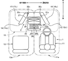
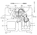
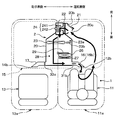
- FIG. 1 (First embodiment) The whole structure of the vehicle air conditioner 2 which concerns on 1st Embodiment is demonstrated using FIG. 1, FIG. In addition, each arrow which shows the front and back, the driver's seat 11 side (right side), and the passenger seat 13 side (left side) shown in FIG. 1, FIG.
- the vehicle air conditioner 2 includes a driver seat side air outlet 12 that blows air into a space 11 a on the driver seat 11 side in the passenger compartment 1 and a space on the passenger seat 13 side. This is applied to a vehicle including a passenger seat side air outlet 14 for blowing air to 13a.
- the driver's seat side outlet 12 has a driver's seat side defroster outlet 12a that blows air toward the windshield W on the driver's seat 11 side in order to prevent the windshield W from fogging.
- the driver's seat-side outlet 12 includes a driver's seat-side face outlet 12b that blows air toward the upper body of the occupant on the driver's seat 11 side, and a driver's seat in order to ensure the comfort of the passenger on the driver's seat 11 side It has a driver's seat side foot blowing part 12c that blows air toward the feet of the 11th passenger.
- FIG. 1 shows only the space 11 a on the driver's seat 11 side in the passenger compartment 1.
- the passenger side air outlet 14 has a passenger seat side defroster outlet (not shown) for blowing air toward the windshield W on the passenger seat 13 side. Further, the passenger seat side outlet 14 blows air toward the passenger seat face blowing portion (not shown) for blowing air toward the passenger's upper body on the passenger seat 13 side and the passenger's foot on the passenger seat 13 side. It has a passenger seat side foot outlet 14c. For convenience, FIG. 2 shows only the foot outlets 12c and 14c.
- the vehicle air conditioner 2 of the present embodiment is accommodated inside the dashboard 15 disposed in the front part of the vehicle interior 1.
- the vehicle air conditioner 2 of the present embodiment has a so-called center-placement type layout that is disposed at the center in the left-right direction of the vehicle.
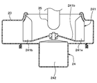
- the vehicle air conditioner 2 includes a casing 20 that constitutes an outer shell thereof.
- Casing 20 of this embodiment is arranged so that it may be located in the central part of the vehicle left-right direction so that a part may be exposed to space 11a at the side of driver's seat 11.
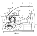
- an inside air introduction port 20 a for introducing vehicle interior air (inside air) from the space 13 a on the passenger seat 13 side, and outside air inside the vehicle compartment (outside air) Is provided with an outside air introduction port 20b.
- the casing 20 accommodates an inside / outside air switching door 21 that opens and closes the inside air introduction port 20a and the outside air introduction port 20b.
- the inside / outside air switching door 21 is connected to a servo motor as a drive unit and is driven to open and close by the servo motor.
- a filter 22 for removing foreign matters such as dust and dirt is accommodated on the downstream side of the air flow of the inside air introduction port 20a and the outside air introduction port 20b. Furthermore, an evaporator 23 as a cooling unit for cooling the air blown into the vehicle interior 1 is accommodated on the downstream side of the air flow of the filter 22 in the casing 20.
- the evaporator 23 constitutes a well-known refrigeration cycle together with a compressor, a condenser, and a decompressor (not shown).
- the evaporator 23 is a heat exchanger that cools the air flowing in the casing 20 by heat-exchanging the low-pressure refrigerant flowing in the refrigeration cycle with the air in the casing 20 and evaporating it.
- a blower 24 that blows air toward the passenger compartment 1 is accommodated on the downstream side of the air flow of the evaporator 23 in the casing 20.
- the blower 24 of the present embodiment is accommodated in the casing 20 so as to be located at the center in the left-right direction of the vehicle.
- blower 24 of the present embodiment includes a centrifugal impeller 241 and a blower motor 242 that rotates the impeller 241.
- the air blower 24 of this embodiment is a suction type fan which sucks in air from the air flow downstream side of the evaporator 23.
- a driver seat side suction port 20 c for sucking air from the space 11 a on the driver seat 11 side is provided as an air suction port other than the inside air introduction port 20 a and the outside air introduction port 20 b.
- the driver-seat-side suction port 20c is formed in a portion of the casing 20 exposed to the driver-seat 11-side space 11a (in the vicinity of the passenger's feet) so that air is directly sucked from the driver-seat 11-side space 11a. ing.
- the casing 20 accommodates a suction opening / closing door 25 for opening and closing the driver's seat side suction opening 20c.
- the suction opening / closing door 25 is connected to a servo motor as a drive unit and is driven to open / close by the servo motor.
- the passage from the driver's seat side suction port 20c to the blower 24 in the casing 20 has elements such as the filter 22 and the evaporator 23 that provide ventilation resistance like the passages from the introduction ports 20a and 20b to the blower 24. Few. For this reason, when the driver's seat side suction port 20c is opened by the suction opening / closing door 25, even if the inside air introduction port 20a and the outside air introduction port 20b are opened, the driver's seat is provided via the driver seat side suction port 20c. The air in the space 11 a on the 11 side is sucked into the blower 24.
- a heater core 26 and an electric heater 27 are accommodated on the downstream side of the air flow of the blower 24 as a heating unit that heats the air blown into the vehicle interior 1.
- the heater core 26 is a heat exchanger for heating that heats air blown into the vehicle interior 1 using engine cooling water that cools a vehicle engine (not shown) as a heat source.
- the heater core 26 is arranged on the upstream side of the air flow of the electric heater 27.
- the electric heater 27 is a heater (for example, a PTC heater) that generates heat when energized, and an auxiliary heating device that heats the air blown into the vehicle interior 1 in a state where the air cannot be sufficiently heated by the heater core 26. It is.
- a heating-side bypass passage 28 is formed on the side of the heating unit (heater core 26, electric heater 27) in the casing 20.
- the heating-side bypass passage 28 is a passage for allowing the air blown into the vehicle interior 1 to flow around the heating unit (the heater core 26 and the electric heater 27).
- an air mix door 29 is disposed between the evaporator 23 and the heating unit (heater core 26, electric heater 27) in the casing 20.
- the air mix door 29 adjusts the air volume of the air flowing to the heating unit (heater core 26, electric heater 27) and the air flowing to the heating-side bypass passage 28, and adjusts the temperature of the air blown into the vehicle interior 1.
- the air mix door 29 is connected to a servo motor as a drive unit.
- a plurality of driver-seat-side openings 30a to 30c communicating with the respective blowing parts 12a to 12c of the driver-seat-side outlet 12 via the outlet ducts 16a to 16c are provided at the most downstream part of the air flow in the casing 20. Yes.
- the driver seat side openings 30a to 30c are provided with outlet switching doors 31a to 31c for opening and closing the openings 30a to 30c.
- the air outlet switching doors 31a to 31c are connected to a servo motor as a drive unit and are opened and closed by the servo motor.
- FIG. 2 shows only the passenger seat side opening 32c communicating with the passenger seat foot blowing portion 14c.
- each passenger seat side opening part 32c is provided with the blower outlet switching door 33c which opens and closes each opening part 32c.
- the blower outlet switching door 33c is connected to a servo motor as a drive unit (not shown) and is opened and closed by the servo motor.
- the suction opening / closing door 25, and the outlet switching doors 31a to 31c, 33c depending on the settings of the inside / outside air switching door 21, the suction opening / closing door 25, and the outlet switching doors 31a to 31c, 33c, the air suction mode into the casing 20 and the vehicle interior 1 are entered.
- the blowout mode can be switched. Therefore, in this embodiment, the inside / outside air switching door 21, the suction opening / closing door 25, and each of the outlet switching doors 31a to 31c, 33c constitute a mode switching unit that switches between the suction mode and the blowing mode.
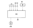
- the air conditioning control device 40 includes a well-known microcomputer including a CPU, a memory, and the like and peripheral circuits thereof, and is a device that performs various calculations and processes based on a control program stored in the memory.
- the air-conditioning control device 40 On the input side of the air-conditioning control device 40, there are an inside air sensor that detects the temperature inside the vehicle (inside temperature), an outside air sensor that detects the outside temperature (outside temperature), a solar radiation sensor that detects the amount of solar radiation in the vehicle interior 1, and an evaporator.
- a cooling water temperature sensor 42 that detects the temperature of the engine cooling water
- a seating sensor 43 that detects whether a passenger is seated on each seat 11, 13, and the like are connected to the input side of the air conditioning control device 40.
- an operation panel 45 provided with various switches such as an air conditioning operation switch, a temperature setting switch for setting the passenger compartment temperature, and an air conditioning mode selection switch is connected to the input side of the air conditioning control device 40.
- a blower motor 242 of the blower 24, a servo motor that drives the various doors 21, 25, 29, 31a to 31c, 33c, and the like are connected to the output side of the air conditioning control device 40 as control target devices.
- the air conditioning control device 40 executes the air conditioning control process according to the control program stored in the memory.
- the air conditioning control device 40 of the present embodiment executes the following air conditioning control processing when the air conditioning mode selected by the selection switch is a cooling mode in which the temperature of the passenger compartment 1 is lowered below the outside air temperature.
- the air conditioning control device 40 reads the detection signal of the air conditioning control sensor group 41 and the operation signal of the temperature setting switch of the operation panel 45, and calculates the target blowing temperature TAO that is the target temperature of the air blown into the vehicle interior 1. To do.
- the target blowing temperature TAO is calculated by the following [Equation 1].
- TAO Kset ⁇ Tset ⁇ Kr ⁇ Tr ⁇ Kam ⁇ Tam ⁇ Ks ⁇ Ts + C [Equation 1]
- Tset is the set temperature of the passenger compartment 1 set by the temperature setting switch
- Tr is the passenger compartment temperature detected by the inside air sensor
- Tam the outside air temperature detected by the outside air sensor
- Ts is detected by the solar radiation sensor.
- Kset, Kr, Kam, and Ks are control gains
- C is a correction constant.
- each control target device is determined according to the target outlet temperature TAO, the temperature of the evaporator 23 detected by the evaporator temperature sensor, and the temperature of the engine coolant detected by the coolant temperature sensor 42.
- the blower 24 is set with reference to a control map stored in the air conditioning control device 40 in advance. Specifically, the blower 24 is set with a control signal to be output to the blower motor 242 so that the amount of air blown from the blower 24 increases as the target blowing temperature TAO decreases.
- the opening degree of the air mix door 29 is determined according to the target blowing temperature TAO, the temperature Te of the evaporator 23, the temperature Tw of the engine cooling water, and the temperature of the electric heater 27. For example, when it is desired to obtain high cooling performance when the TAO is in a very low temperature region, the air mix door 29 is set to a position where the heating side bypass passage 28 is fully opened. Moreover, when TAO becomes an extremely high temperature region and high heating performance is desired, the air mix door 29 is set to a position where the heating side bypass passage 28 is fully closed. In addition, about the door opening degree of the air mix door 29, it sets similarly also in the heating mode mentioned later.
- the inside / outside air switching door 21 opens the outside air introduction port 20b, and inside / outside air switching
- the door 21 is set to one of the inside air modes in which the inside air inlet 20a is opened.
- the suction mode is basically set to the outside air mode so that the outside air is introduced, and is set to the inside air mode when the target blowing temperature TAO is in a very low temperature range and high cooling performance is desired. Is done.
- the suction opening / closing door 25 it sets to the position which closes the driver's seat side suction inlet 20c.
- the air blowing mode into the passenger compartment 1 is mainly set to the face mode in which air is blown out from the driver seat side face blowing portion 12b and the passenger seat side face blowing portion 14b.
- the opening switching doors 31a to 31c, 33c open the openings 30b communicating with the face blowing parts 12b, 14b, and the other openings 30a, 30c, 32c are closed.
- the blowing mode may be set to the defroster mode in which air is blown out from each defroster blowing portion 12a.
- the rotational speed of the compressor, the throttle opening of the decompressor, etc. are set with reference to a control map stored in advance in the air conditioning control device 40 so that the evaporator 23 exhibits an endothermic effect.
- the electric heater 27 is basically deenergized.
- the air conditioning control device 40 of the present embodiment executes the following air conditioning control processing when the air conditioning mode selected by the selection switch is a heating mode in which the temperature of the vehicle interior 1 is raised above the outside air temperature. .
- the air-conditioning control device 40 reads the detection signal of the air-conditioning control sensor group 41 and the operation signal of the temperature setting switch of the operation panel 45, and calculates the target blowing temperature TAO that is the target temperature of the air blown into the vehicle interior 1. To do.
- the target blowout temperature TAO is calculated by the above [Equation 1] as in the cooling mode.
- the temperature Te of the evaporator 23 detected by the evaporator temperature sensor the temperature Tew of the engine cooling water detected by the cooling water temperature sensor 42, and the detection result of the seating sensor 43, Determine the operation of the controlled device.
- the blower 24 is set with reference to a control map stored in the air conditioning control device 40 in advance. Specifically, a control signal to be output to the blower motor 242 is set in the blower 24 so that the blown amount of the blower 24 increases as the target blowing temperature TAO increases.
- the electric heater 27 is energized when the engine cooling water temperature Tw is low and the heater core 26 alone cannot secure the heating performance, or when the target blowout temperature TAO is in an extremely high temperature range and high heating performance is desired.
- the operation of the refrigeration cycle is basically stopped.
- the inside / outside air switching door 21, the suction opening / closing door 25, and the outlet switching doors 31a to 31c, 33c constituting the mode switching unit are set according to the seating state of the occupant in the driver seat 11 and the passenger seat 13. Can be switched.
- the inside / outside air switching door 21 introduces inside air so that outside air is basically introduced.
- the position is set to close the mouth 20a.
- the suction opening / closing door 25 it sets to the position which closes the driver's seat side suction inlet 20c.
- the position where the suction opening / closing door 25 opens the inside air inlet 20a so that the inside air is introduced when the TAO is in an extremely high temperature range and high heating performance is desired.
- the blowing mode is set to a foot mode in which air is blown out from both the driver seat side foot blowing portion 12c and the passenger seat side foot blowing portion 14c.
- the openings 30c and 32c communicating with the foot outlets 12c and 14c are opened by the outlet switching doors 31a to 31c and 33c, and the other openings 30a and 30b are closed.
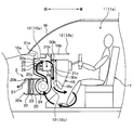
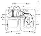
- FIG. 4 shows an example in which air is sucked from the inside air inlet 20a.
- the suction opening / closing door 25 is set to a position where the driver's seat side suction port 20c is opened. Further, the inside / outside air switching door 21 is set at a position where either the inside air introduction port 20a or the outside air introduction port 20b is closed.
- the driver's seat side suction port 20c is opened, even if the inside air introduction port 20a and the outside air introduction port 20b are opened, the driver's seat 11 is provided via the driver seat side suction port 20c. The air in the side space 11 a is sucked into the blower 24.
- the blowing mode is set to a foot mode in which air is blown out from the driver seat side foot blowing portion 12c.
- the air outlet switching doors 31a to 31c, 33c open the opening 30c communicating with the driver's seat side foot air outlet 12c, and the other openings 30a, 30b, 32c are closed.
- the vehicle air conditioner 2 capable of reducing the heating load can be realized with a simple structure. That is, the vehicular air conditioner 2 of the present embodiment opens the driver seat side suction port 20c and sucks air from the space 11a on the driver seat 11 side where air is blown out from the driver seat side outlet 12. The structure can be switched to the mode.
- the heating load can be reduced.
- the driver's seat side suction port 20c is formed in a portion exposed to the space 11a on the driver's seat 11 side in the casing 20, and air is directly supplied from the space 11a on the driver's seat 11 side. It has a structure that sucks in. According to this, since it is not necessary to provide a separate dedicated duct, the vehicle air conditioner 2 can be simplified.
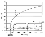
- FIG. 8 shows that the 600 W electric heater 27 is energized in an environment where the passenger compartment 1 is at a very low temperature (below freezing point), and all the air (air volume 30 m3 / h) passing through the electric heater 27 is operated. It is an experimental result at the time of blowing out from the seat side foot blowing part 12c.
- the solid line A is the temperature change of the air blown from the driver seat side outlet 12
- the alternate long and short dash line B is the change in the ambient temperature near the foot of the driver seat 11
- the two-dot chain line C is the foot of the passenger seat 13. The change in ambient temperature in the vicinity is shown.
- the ambient temperature near the feet of the driver's seat 11 becomes higher than the ambient temperature near the feet of the passenger seat 13 as time elapses. For this reason, it is possible to reduce the heating load by causing air near the feet of the driver's seat 11 having a higher atmospheric temperature to flow into the heating unit (the heater core 26 and the electric heater 27) than in the vicinity of the feet of the passenger seat 13. it can. Further, when air near the feet of the driver's seat 11 having a higher atmospheric temperature than the feet of the passenger seat 13 is caused to flow into the heating unit (the heater core 26 and the electric heater 27), the temperature of the air blown into the vehicle interior 1 is Since it raises, the immediate effect of the heating of the vehicle interior 1 can be improved.
- the vehicle air conditioner 2 of this embodiment accommodates the air blower 24 in the casing 20 disposed so as to be positioned in the center portion in the left-right direction of the vehicle, and a portion positioned in the center portion of the casing 20 in the left-right direction of the vehicle.
- the driver's seat side suction port 20c is formed in this.
- the air sucked from the driver side suction port 20c passes through the cooling part (evaporator 23) that cools the air blown into the passenger compartment 1, the air sucked from the driver side suction port 20c.
- the heat of the air is dissipated in the cooling section. This is not preferable because the temperature of the air flowing into the heating unit decreases and the heating load of the vehicle air conditioner 2 increases.
- the evaporator 23 includes the housing position of the heating unit (heater core 26, electric heater 27), the housing position of the blower 24, and the opening position of the driver seat side suction port 20c.
- the air flow is set on the downstream side.
- the electric heater 27 is disposed in the air passage from the driver seat side suction port 20 c to the driver seat side outlet 12 in the casing 20. According to this, even when the temperature of the heater core 26 is low when the vehicle interior 1 is heated, the air blown into the vehicle interior 1 can be heated by energizing the electric heater 27.
- the driver's seat side suction port 20c is formed in a portion (near the feet of the occupant) located below the driver's seat side face blowing portion 12b in the casing 20. According to this, since warm air circulates in the vicinity of the feet of the passenger on the driver's seat 11 side, it is possible to suppress the warm air on the driver's seat 11 side from rising near the head of the passenger. Thereby, a passenger
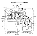
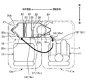
- the vehicle air conditioner 2 includes a semi-centered layout that is disposed in the dashboard 15 so as to straddle the vehicle laterally center portion and the passenger seat 13 side. It has become.
- the casing 20 of the present embodiment is arranged so that the upstream side of the air flow is located on the passenger seat 13 side, and the downstream side of the air flow is located at the center in the left-right direction of the vehicle.
- the heater core 26 is disposed on the downstream side of the evaporator 23 in the casing 20, and the blower 24 is disposed on the downstream side of the heater core 26.
- the air blower 24 of this embodiment is accommodated in the casing 20 so that it may be located in the center part of the vehicle left-right direction.
- a driver seat side suction port 20c is formed on the side of the blower 24 in the casing 20 (driver seat 11 side), and a suction opening / closing door 25 that opens and closes the driver seat side suction port 20c is provided. Contained.
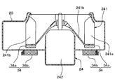
- the blower 24 of the present embodiment is a heater-integrated blower incorporating an electric heater 34.
- the blower 24 incorporates a heating element 34a made of a conductive material and an electric heater 34 including an induction heating coil 34b.
- the electric heater 34 of this embodiment when a high-frequency alternating current is supplied to the induction heating coil 34b, the heat generated in the heating element 34a is sucked into the blower 24 through the main plate 241b and the blade 241a. It is configured to release heat to the air and heat it.
- the heating element 34a is an element that generates Joule heat by resistance when a current flows.
- the heating element 34a of the present embodiment is provided on the main plate 241b that supports one end of the blade 241a of the impeller 241 outside the ventilation path of the blower 24. Note that the blade 241a and the main plate 241b themselves may function as a heating element by configuring the blade 241a and the main plate 241b with a conductive material.
- the induction heating coil 34b is a coil that generates an eddy current in the heating element 34a by changing the magnetic field around the heating element 34a when a high-frequency alternating current is supplied.
- the induction heating coil 34 b of the present embodiment is disposed outside the ventilation path of the blower 24 and in a portion facing the heat generating element 34 a in the casing 20.
- the electric heater 34 is energized in the heating mode.
- the air introduced from one of the inside air introduction port 20a and the outside air introduction port 20b passes through the evaporator 23 as shown by the thick arrow in FIG. Then, it flows into the heater core 26 and is heated. The air heated by the heater core 26 is sucked into the blower 24 and heated by the electric heater 34 built in the blower 24, and then blown out from the foot blowing portions 12c and 14c. Thereby, the space 11a on the driver's seat 11 side and the space 13a on the passenger seat 13 side in the passenger compartment 1 are each warmed.
- FIG. 9 shows an example in which air is sucked from the inside air introduction port 20a.
- the air in the space 11a on the driver's seat 11 side is sucked into the blower 24 through the driver's seat side suction port 20c, as indicated by the thick arrow in FIG.
- the air sucked into the blower 24 is heated by the electric heater 34 built in the blower 24 and then blown out from the driver's seat side foot blowing portion 12c.
- the space 11a on the driver's seat 11 side in the passenger compartment 1 is concentrated and warmed.
- the vehicle air conditioner 2 of this embodiment described above has a structure that can be switched to the driver seat heating mode, and the driver seat side suction port 20c is exposed to the space 11a on the driver seat 11 side in the casing 20. It is formed in the part which did. Therefore, similarly to the first embodiment, the vehicle air conditioner 2 capable of reducing the heating load can be realized with a simple structure.
- the blower 24 a heater built-in type blower incorporating an electric heater 34 is employed. According to this, compared with the case where the blower 24 and the electric heater 27 are configured separately as in the first embodiment, the space for accommodating the electric heater 34 in the casing 20 can be reduced. As a result, it is possible to improve the mountability of the vehicle air conditioner 2 on the vehicle.
- the heating element 34a and the induction heating coil 34b constituting the electric heater 34 are arranged outside the ventilation path of the blower 24 as in this embodiment, an increase in ventilation resistance by the electric heater 34 is suppressed. Thus, power consumption in the blower 24 and the like can be suppressed.
- the electric heater may be constituted by an infrared heater 35 that heats the blade 241a by irradiating the blade 241a with an infrared ray when energized. This can also reduce the space for housing the electric heater in the casing 20 and suppress the increase in ventilation resistance by the electric heater, thereby suppressing the power consumption in the blower 24 and the like.
- heating the air on the air suction side of the impeller 241 improves the heat transfer rate to the air by the “leading edge effect” rather than heating the air on the air blowing side. For this reason, it is desirable to arrange the infrared heater 35 on the air suction side of the impeller 241 so that the front edge of the blade 241a is heated. Further, it is desirable that the blade 241a and the main plate 241b are made of a non-metallic material having high thermal conductivity so that the temperature appropriately rises when irradiated with infrared rays from the infrared heater 35.
- the air flow path in the casing 20 is divided into a first air flow path 36a through which the outside air circulates by the partition member 36 and a second air flow path 36b through which the internal air circulates.
- the vehicle air conditioner 2 will be described.
- the vehicle air conditioner 2 of this embodiment is accommodated in the casing 20 so that the filter 22, the evaporator 23, and the heater core 26 straddle the air flow paths 36a and 36b.
- the inside / outside air switching door 21 of the present embodiment has an inside air door 21a for opening and closing the inside air introduction port 20a and an outside air door 21b for opening and closing the outside air introduction port 20b, and each introduction port 20a, 20b can be opened and closed individually. It has become.
- a heating-side bypass passage 28 is formed in each air flow path 36a, 36b, and an air mix door 29 is accommodated in each air flow path 36a, 36b.
- first and second air blowers 24 a and 24 b constituting the blower 24 are accommodated in the air flow paths 36 a and 36 b.
- each of the 1st, 2nd ventilation parts 24a and 24b is comprised with the above-mentioned heater integrated fan.
- the electric heater 34 is energized in the heating mode.
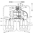
- the inside / outside air switching door 21 is set to a position that opens both the inside air introduction port 20a and the outside air introduction port 20b as shown in FIG. 13 in the normal heating mode. And about the suction opening / closing door 25, it sets to the position which closes the driver's seat side suction inlet 20c. Further, in the normal heating mode, the blowing mode is set to a foot differential mode in which air is blown out from the defroster blowing portions 12a and 14a and the foot blowing portions 12c and 14c.
- the outside air introduced from the outside air inlet 20b passes through the evaporator 23 and then flows into the heater core 26 to be heated.
- the air heated by the heater core 26 is sucked into the first blower 24a and heated by an electric heater (not shown) built in the first blower 24a, and then each defroster blower 12a, 14a. Is blown out. Thereby, window fogging of the windshield W can be suppressed.
- the air introduced from the inside air introduction port 20a passes through the evaporator 23 and then flows into the heater core 26 to be heated.
- the air heated by the heater core 26 is sucked into the second blower 24b and heated by an electric heater (not shown) built in the second blower 24b, and then each foot blower 12c, 14c. Is blown out.
- the space 11a on the driver's seat 11 side and the space 13a on the passenger seat 13 side in the passenger compartment 1 are each warmed.
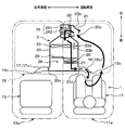
- the inside / outside air switching door 21 is set to a position that closes the inside air introduction port 20a and opens the outside air introduction port 20b. And about the suction opening / closing door 25, it sets to the position which opens the driver's seat side suction inlet 20c.
- the blowing mode is set to a foot differential mode in which air is blown out from each of the defroster blowing portions 12a and 14a and the driver seat side foot blowing portion 12c.
- the outside air introduced from the outside air inlet 20 b passes through the evaporator 23 and then flows into the heater core 26 to be heated. Is done.
- the air heated by the heater core 26 is sucked into the first blower 24a and heated by an electric heater (not shown) built in the first blower 24a, and then each defroster blower 12a, 14a. Is blown out. Thereby, window fogging of the windshield W can be suppressed.
- the air in the space 11a on the driver's seat 11 side is sucked into the second blower 24b through the driver's seat-side suction port 20c.
- the air sucked into the second blower 24b is heated by an electric heater (not shown) built in the second blower 24b and then blown out from the driver's seat side foot blower 12c.
- an electric heater not shown
- the vehicle air conditioner 2 of this embodiment described above has a structure that can be switched to the driver seat heating mode, and the driver seat side suction port 20c is exposed to the space 11a on the driver seat 11 side in the casing 20. It is formed in the part which did. Therefore, similarly to the first embodiment, the vehicle air conditioner 2 capable of reducing the heating load can be realized with a simple structure.
- air is blown out from the driver-seat-side foot blowing part 12c and dry outside air is blown out from the defroster blowing parts 12a and 14a toward the windshield W in the driver-seat heating mode.
- the window fog of the windshield of the vehicle interior 1 can be suppressed while heating the vehicle interior 1.
- the inside air introduction port 20 a is eliminated, and the outside air introduction port 20 b and the driver seat side suction port 20 c are located at the most upstream part of the air flow in the casing 20. Is formed.
- the inside / outside air switching door 21 is provided in the casing 20 so that the outside air introduction port 20b and the driver's seat side suction port 20c can be selectively opened and closed.
- the driver's seat side suction inlet 20c of this embodiment is formed in the site
- the blower 24 is disposed on the upstream side of the evaporator 23 in the casing 20.
- the blower 24 of the present embodiment is a push-type fan that sucks air from the upstream side of the air flow of the evaporator 23.
- a cooling-side bypass passage 23a is formed on the side of the evaporator 23 to flow around the evaporator 23.
- the cooling side bypass passage 23a is provided with a cooling opening / closing door 23b for opening and closing the cooling side bypass passage 23a.
- cooling side bypass passage 23a has no element that provides ventilation resistance, when the cooling side bypass passage 23a is opened by the cooling opening / closing door 23b, the air blown from the blower 24 bypasses the evaporator 23. Then, it flows into the cooling-side bypass passage 23a.
- the inside / outside air switching door 21 is set to a position where the driver's seat side suction port 20c is opened, and the blowing mode is a foot that blows air from the foot blowing portions 12c, 14c.
- the cooling open / close door 23b is set to a position where the cooling bypass path 23a is opened.
- the air in the space 11a on the driver's seat 11 side is sucked into the blower 24 from the driver's seat side suction port 20c and blown out downstream.
- the air blown out from the blower 24 flows into the heater core 26 and the electric heater 27 through the cooling side bypass passage 23a and is heated.
- the air heated with the heater core 26 and the electric heater 27 blows off from each foot blowing part 12c, 14c.
- the space 11a on the driver's seat 11 side and the space 13a on the passenger seat 13 side in the passenger compartment 1 are each warmed.
- the inside / outside air switching door 21 is set to a position where the driver's seat side suction port 20c is opened, and the blowing mode is set to air from the driver's seat side foot outlet 12c. Is set to foot differential mode.
- the cooling open / close door 23b is set to a position where the cooling bypass path 23a is opened.
- the air in the space 11a on the driver's seat 11 side is sucked into the blower 24 from the driver's seat side suction port 20c and blown out downstream.
- the air blown out from the blower 24 flows into the heater core 26 and the electric heater 27 through the cooling side bypass passage 23a and is heated.
- the air heated with the heater core 26 and the electric heater 27 blows off from the driver's seat side foot blowing part 12c.
- the space 11a on the driver's seat 11 side in the passenger compartment 1 is concentrated and warmed.
- the inside / outside air switching door 21 is set to a position where the driver's seat side suction port 20c is opened.
- the blowing mode is set to the face mode in which air is blown out from the driver seat side face blowing portion 12b.
- the cooling open / close door 23b is set to a position where the cooling side bypass passage 23a is closed, and the air mix door 29 is set to a position where the heating side bypass passage 28 is fully opened.
- the air in the space 11a on the driver's seat 11 side is sucked into the blower 24 from the driver's seat side suction port 20c and blown out downstream.
- the air blown out from the blower 24 flows into the evaporator 23 and is cooled.
- the air cooled with the evaporator 23 blows off from the driver's seat side face blowing part 12b. Thereby, the space 11a on the driver's seat 11 side in the passenger compartment 1 is concentrated and cooled.
- the inside / outside air switching door 21 is set to a position where the driver seat side suction port 20c is opened.
- the blowing mode is set to a face mode in which air is blown out from the driver seat side face blowing portion 12b and the passenger seat side face blowing portion 14b.
- the cooling open / close door 23b is set to a position where the cooling side bypass passage 23a is closed, and the air mix door 29 is set to a position where the heating side bypass passage 28 is fully opened.
- the air in the space 11a on the driver's seat 11 side is sucked into the blower 24 from the driver's seat side suction port 20c and blown out downstream.
- the air blown out from the blower 24 flows into the evaporator 23 and is cooled.
- the air cooled with the evaporator 23 is blown off from the driver's seat side face blowing part 12b and the passenger's seat side face blowing part 14b.
- the vehicle air conditioner 2 of this embodiment described above has a structure that can be switched to the driver seat heating mode, and the driver seat side suction port 20c is exposed to the space 11a on the driver seat 11 side in the casing 20. It is formed in the part which did. Therefore, similarly to the first embodiment, the vehicle air conditioner 2 capable of reducing the heating load can be realized with a simple structure.
- the vehicle air conditioner 2 since the vehicle air conditioner 2 according to the present embodiment has a structure that can be switched to the driver's seat cooling mode, the cooling load can be reduced.
- the vehicle air conditioner 2 has a semi-center layout that is disposed across the center of the vehicle in the left-right direction and the passenger seat 13 side in the dashboard 15. .
- the casing 20 of the present embodiment is arranged so that the upstream side of the air flow is located on the passenger seat 13 side, and the downstream side of the air flow is located at the center in the left-right direction of the vehicle.
- the heater core 26 is disposed on the downstream side of the evaporator 23 in the casing 20, and the blower 24 is disposed on the downstream side of the heater core 26.
- the air blower 24 of this embodiment is accommodated in the casing 20 so that it may be located in the center part of the vehicle left-right direction.
- the inside air introduction port 20a, the outside air introduction port 20b, and the driver seat side suction port 20c are arranged on the upstream side of the filter 22 and the evaporator 23, and are arranged on the passenger seat 13 side.
- driver's seat side suction port 20c is formed at a position closer to the space 11a on the driver's seat 11 side than the inside air introduction port 20a and on the surface of the casing 20 on the vehicle rear side.
- the blowing mode is set to a foot mode in which air is blown out from the driver's seat side foot blowing portion 12c.
- the inside / outside air switching door 21 closes the outside air introduction port 20b
- the suction opening / closing door 25 closes the inside air introduction port 20a and opens the driver seat side suction port 20c. Therefore, as shown by the thick arrow in FIG. 18, air is sucked in through the driver seat side suction port 20c.
- the driver seat side suction port 20c is closer to the space 11a on the driver seat 11 side than the inside air introduction port 20a, the driver seat side suction port 20c is closer to the driver seat 11 side space 11a than when air is sucked in via the inside air introduction port 20a. Air is easily inhaled.
- the air sucked from the driver seat side suction port 20c is heated by the heater core 26 and then blown out from the driver seat side foot blowing portion 12c. Thereby, the space 11a on the driver's seat 11 side in the passenger compartment 1 is concentrated and warmed.
- the blowing mode is set to a foot mode in which air is blown out from the driver seat side foot blowing portion 12c and the passenger seat side foot blowing portion 14c.
- the suction opening / closing door 25 closes the driver's seat side suction opening 20c, and the inside / outside air switching door 21 opens either the outside air introduction opening 20b or the inside air introduction opening 20a. Therefore, air is sucked through either the outside air inlet 20b or the inside air inlet 20a.
- the sucked air is heated by the heater core 26 and then blown out from the driver seat side foot blowing portion 12c and the passenger seat side foot blowing portion 14c.
- the space 11a on the driver's seat 11 side and the space 13a on the passenger seat 13 side in the passenger compartment 1 are both warmed.
- the vehicle air conditioner 2 of the present embodiment described above has a structure that can be switched to the driver seat heating mode, and the driver seat side suction port 20 c is formed in the casing 20. Therefore, similarly to the first embodiment, the vehicle air conditioner 2 capable of reducing the heating load can be realized with a simple structure.
- the present invention is not limited to this.
- the part where the driver's seat side suction port 20c is provided may be a part exposed to the space 11a on the driver's seat 11 side in the casing 20.
- the electric heater 27 is provided as an auxiliary heating device in addition to the heater core 26 .
- the present invention is not limited thereto, and the electric heater 27 may be omitted.
- the driver seat cooling mode may be set as in the fourth embodiment to reduce not only the heating load but also the cooling load.
- a humidifier for example, a deodorizing device, an aroma addition device, an air quality component (for example, ion) addition device, etc. are provided in the air path from the driver seat side suction port 20c to the driver seat side outlet 12.
- the effects of these devices may be concentrated on the driver's seat occupant.
Landscapes
- Engineering & Computer Science (AREA)
- Mechanical Engineering (AREA)
- Physics & Mathematics (AREA)
- Thermal Sciences (AREA)
- Air-Conditioning For Vehicles (AREA)
Priority Applications (2)
| Application Number | Priority Date | Filing Date | Title |
|---|---|---|---|
| US14/904,902 US10618371B2 (en) | 2013-07-18 | 2014-06-19 | Air conditioner for vehicle |
| CN201480040382.9A CN105377598B (zh) | 2013-07-18 | 2014-06-19 | 车辆用空调装置 |
Applications Claiming Priority (4)
| Application Number | Priority Date | Filing Date | Title |
|---|---|---|---|
| JP2013-149371 | 2013-07-18 | ||
| JP2013149371 | 2013-07-18 | ||
| JP2014-108319 | 2014-05-26 | ||
| JP2014108319A JP6318854B2 (ja) | 2013-07-18 | 2014-05-26 | 車両用空調装置 |
Publications (1)
| Publication Number | Publication Date |
|---|---|
| WO2015008434A1 true WO2015008434A1 (ja) | 2015-01-22 |
Family
ID=52345918
Family Applications (1)
| Application Number | Title | Priority Date | Filing Date |
|---|---|---|---|
| PCT/JP2014/003303 Ceased WO2015008434A1 (ja) | 2013-07-18 | 2014-06-19 | 車両用空調装置 |
Country Status (4)
| Country | Link |
|---|---|
| US (1) | US10618371B2 (enExample) |
| JP (1) | JP6318854B2 (enExample) |
| CN (1) | CN105377598B (enExample) |
| WO (1) | WO2015008434A1 (enExample) |
Cited By (2)
| Publication number | Priority date | Publication date | Assignee | Title |
|---|---|---|---|---|
| CN106166932A (zh) * | 2015-05-20 | 2016-11-30 | 标致·雪铁龙汽车公司 | 具有根据运输工具的预计路线限定的除污策略的空气除污装置 |
| WO2022230446A1 (ja) * | 2021-04-27 | 2022-11-03 | 株式会社デンソー | 車両に搭載される空調ユニット |
Families Citing this family (37)
| Publication number | Priority date | Publication date | Assignee | Title |
|---|---|---|---|---|
| EP3418089B1 (en) * | 2013-03-13 | 2020-02-12 | Bergstrom, Inc. | Air conditioning system utilizing heat recovery ventilation for fresh air supply and climate control |
| JP6015607B2 (ja) * | 2013-09-18 | 2016-10-26 | 株式会社デンソー | 車両用空調ユニット |
| WO2015061370A1 (en) | 2013-10-21 | 2015-04-30 | Milwaukee Electric Tool Corporation | Adapter for power tool devices |
| WO2015065495A1 (en) | 2013-11-04 | 2015-05-07 | Bergstrom, Inc. | Low profile air conditioning system |
| US9783024B2 (en) | 2015-03-09 | 2017-10-10 | Bergstrom Inc. | System and method for remotely managing climate control systems of a fleet of vehicles |
| JP6319513B2 (ja) * | 2015-04-20 | 2018-05-09 | 株式会社デンソー | 送風装置 |
| JP2017013704A (ja) * | 2015-07-03 | 2017-01-19 | 株式会社ヴァレオジャパン | 車両用空調装置及びその車両用空調装置を搭載した車両 |
| JP6500995B2 (ja) | 2015-10-26 | 2019-04-17 | 株式会社デンソー | 車両用空調装置 |
| DE112016005531T5 (de) * | 2015-12-02 | 2018-08-30 | Denso Corporation | Luftströmungssteuersystem |
| US9874384B2 (en) | 2016-01-13 | 2018-01-23 | Bergstrom, Inc. | Refrigeration system with superheating, sub-cooling and refrigerant charge level control |
| US10589598B2 (en) | 2016-03-09 | 2020-03-17 | Bergstrom, Inc. | Integrated condenser and compressor system |
| JP2018001971A (ja) * | 2016-07-01 | 2018-01-11 | 株式会社Soken | 空調装置 |
| US12420616B2 (en) | 2016-08-22 | 2025-09-23 | Bergstrom, Inc. | Multi-compressor oil migration mitigation climate system |
| US10081226B2 (en) | 2016-08-22 | 2018-09-25 | Bergstrom Inc. | Parallel compressors climate system |
| US10562372B2 (en) | 2016-09-02 | 2020-02-18 | Bergstrom, Inc. | Systems and methods for starting-up a vehicular air-conditioning system |
| JP6658898B2 (ja) * | 2016-09-08 | 2020-03-04 | 株式会社デンソー | 車両用空調装置 |
| KR101836694B1 (ko) * | 2016-09-12 | 2018-03-08 | 현대자동차주식회사 | 내-외기 분리 유동 제어가 가능한 자동차용 공조 장치 |
| US10675948B2 (en) | 2016-09-29 | 2020-06-09 | Bergstrom, Inc. | Systems and methods for controlling a vehicle HVAC system |
| US10369863B2 (en) | 2016-09-30 | 2019-08-06 | Bergstrom, Inc. | Refrigerant liquid-gas separator with electronics cooling |
| US10724772B2 (en) | 2016-09-30 | 2020-07-28 | Bergstrom, Inc. | Refrigerant liquid-gas separator having an integrated check valve |
| WO2018096871A1 (ja) * | 2016-11-23 | 2018-05-31 | 株式会社デンソー | 車両用空調装置 |
| JP6729606B2 (ja) * | 2017-03-14 | 2020-07-22 | 株式会社デンソー | 車両用空調装置 |
| US11448441B2 (en) | 2017-07-27 | 2022-09-20 | Bergstrom, Inc. | Refrigerant system for cooling electronics |
| US10532661B2 (en) | 2017-08-21 | 2020-01-14 | Ford Global Technologies, Llc | System and method for heating electrified vehicle |
| JP6958221B2 (ja) * | 2017-10-20 | 2021-11-02 | 株式会社デンソー | 車両用空調装置 |
| JP6969985B2 (ja) * | 2017-11-14 | 2021-11-24 | トヨタ自動車株式会社 | 車両用空調装置 |
| JP7049745B2 (ja) * | 2018-01-09 | 2022-04-07 | 株式会社ヴァレオジャパン | 車両用空調装置の制御方法 |
| US11420496B2 (en) | 2018-04-02 | 2022-08-23 | Bergstrom, Inc. | Integrated vehicular system for conditioning air and heating water |
| CN108944343B (zh) * | 2018-08-22 | 2024-02-06 | 安徽安凯汽车股份有限公司 | 一种带导风管的内置空调罩盖 |
| JP7155771B2 (ja) * | 2018-09-06 | 2022-10-19 | 株式会社デンソー | 冷凍サイクル装置 |
| JP7147499B2 (ja) * | 2018-11-19 | 2022-10-05 | 株式会社デンソー | 遠心式送風機 |
| JP7052758B2 (ja) * | 2019-03-04 | 2022-04-12 | 株式会社デンソー | 車両用空調装置 |
| KR102814379B1 (ko) * | 2019-09-09 | 2025-05-29 | 현대자동차주식회사 | 차량용 공조시스템 |
| JP7531327B2 (ja) * | 2020-06-26 | 2024-08-09 | 本田技研工業株式会社 | 車両用空調装置 |
| EP4026711A1 (en) * | 2021-01-12 | 2022-07-13 | Volvo Truck Corporation | A method for regulating a thermal control system of a cabin of a vehicle |
| FR3121872B1 (fr) * | 2021-04-16 | 2023-06-09 | Faurecia Interieur Ind | Véhicule avec soufflage d’air porté par les sièges avant |
| US20230249515A1 (en) * | 2022-02-04 | 2023-08-10 | Ford Global Technologies, Llc | Heating ventilation and cooling system for a vehicle |
Citations (8)
| Publication number | Priority date | Publication date | Assignee | Title |
|---|---|---|---|---|
| JPH04292216A (ja) * | 1991-03-20 | 1992-10-16 | Nissan Shatai Co Ltd | 車両用空調装置 |
| JP2003080921A (ja) * | 2001-09-14 | 2003-03-19 | Calsonic Kansei Corp | 送風装置および車両用空調装置 |
| JP2003136936A (ja) * | 2001-11-07 | 2003-05-14 | Zexel Valeo Climate Control Corp | 車両用空調装置 |
| JP2007046893A (ja) * | 2005-08-06 | 2007-02-22 | Microhellix Systems Gmbh | 特に車両内の空気流加熱のための電気ヒータモジュール |
| JP2007118630A (ja) * | 2005-10-25 | 2007-05-17 | Valeo Thermal Systems Japan Corp | 自動車用空調装置の内外気切換装置の制御方法及び装置 |
| JP2007137282A (ja) * | 2005-11-18 | 2007-06-07 | Japan Climate Systems Corp | 空調装置 |
| JP2008296717A (ja) * | 2007-05-31 | 2008-12-11 | Denso Corp | 車両用空調装置 |
| JP2010025527A (ja) * | 2008-07-24 | 2010-02-04 | Denso Corp | 電気ヒータ、車両用空調装置および電気ヒータの製造方法 |
Family Cites Families (10)
| Publication number | Priority date | Publication date | Assignee | Title |
|---|---|---|---|---|
| JPS59137212A (ja) | 1983-01-26 | 1984-08-07 | Nippon Denso Co Ltd | 自動車用空気清浄器兼空調装置 |
| JP4224939B2 (ja) * | 2000-03-31 | 2009-02-18 | 株式会社デンソー | 車両用空調装置 |
| US6669550B1 (en) * | 2002-08-16 | 2003-12-30 | Delphi Technologies, Inc. | Heating, ventilation, and air conditioning system having improved air warm-up |
| US7247088B2 (en) * | 2003-09-25 | 2007-07-24 | Mazda Motor Corporation | Air conditioner for vehicle |
| JP2005225412A (ja) | 2004-02-16 | 2005-08-25 | Nissan Motor Co Ltd | 車両用空調装置 |
| US20080248736A1 (en) * | 2007-04-03 | 2008-10-09 | Denso Corporation | Air conditioner for vehicle |
| JP4332901B2 (ja) * | 2007-08-01 | 2009-09-16 | 株式会社デンソー | 機器制御方法及び機器制御装置 |
| JP5018761B2 (ja) | 2008-12-18 | 2012-09-05 | 株式会社デンソー | 車両用空調装置 |
| JP2012106667A (ja) * | 2010-11-18 | 2012-06-07 | Toyota Industries Corp | 車両における空調装置 |
| US9597945B2 (en) * | 2011-06-09 | 2017-03-21 | Ford Global Technologies, Llc | Automotive HVAC system with suction surfaces to control local airflow |
-
2014
- 2014-05-26 JP JP2014108319A patent/JP6318854B2/ja active Active
- 2014-06-19 CN CN201480040382.9A patent/CN105377598B/zh active Active
- 2014-06-19 US US14/904,902 patent/US10618371B2/en not_active Expired - Fee Related
- 2014-06-19 WO PCT/JP2014/003303 patent/WO2015008434A1/ja not_active Ceased
Patent Citations (8)
| Publication number | Priority date | Publication date | Assignee | Title |
|---|---|---|---|---|
| JPH04292216A (ja) * | 1991-03-20 | 1992-10-16 | Nissan Shatai Co Ltd | 車両用空調装置 |
| JP2003080921A (ja) * | 2001-09-14 | 2003-03-19 | Calsonic Kansei Corp | 送風装置および車両用空調装置 |
| JP2003136936A (ja) * | 2001-11-07 | 2003-05-14 | Zexel Valeo Climate Control Corp | 車両用空調装置 |
| JP2007046893A (ja) * | 2005-08-06 | 2007-02-22 | Microhellix Systems Gmbh | 特に車両内の空気流加熱のための電気ヒータモジュール |
| JP2007118630A (ja) * | 2005-10-25 | 2007-05-17 | Valeo Thermal Systems Japan Corp | 自動車用空調装置の内外気切換装置の制御方法及び装置 |
| JP2007137282A (ja) * | 2005-11-18 | 2007-06-07 | Japan Climate Systems Corp | 空調装置 |
| JP2008296717A (ja) * | 2007-05-31 | 2008-12-11 | Denso Corp | 車両用空調装置 |
| JP2010025527A (ja) * | 2008-07-24 | 2010-02-04 | Denso Corp | 電気ヒータ、車両用空調装置および電気ヒータの製造方法 |
Cited By (3)
| Publication number | Priority date | Publication date | Assignee | Title |
|---|---|---|---|---|
| CN106166932A (zh) * | 2015-05-20 | 2016-11-30 | 标致·雪铁龙汽车公司 | 具有根据运输工具的预计路线限定的除污策略的空气除污装置 |
| WO2022230446A1 (ja) * | 2021-04-27 | 2022-11-03 | 株式会社デンソー | 車両に搭載される空調ユニット |
| JP7613243B2 (ja) | 2021-04-27 | 2025-01-15 | 株式会社デンソー | 車両に搭載される空調ユニット、車両、車両に空調ユニットを配置する方法 |
Also Published As
| Publication number | Publication date |
|---|---|
| CN105377598A (zh) | 2016-03-02 |
| CN105377598B (zh) | 2018-01-23 |
| JP2015037926A (ja) | 2015-02-26 |
| US20160144685A1 (en) | 2016-05-26 |
| JP6318854B2 (ja) | 2018-05-09 |
| US10618371B2 (en) | 2020-04-14 |
Similar Documents
| Publication | Publication Date | Title |
|---|---|---|
| JP6318854B2 (ja) | 車両用空調装置 | |
| JP5556619B2 (ja) | 車両用空調装置 | |
| CN103502029B (zh) | 用于车辆的空调器 | |
| US8460073B2 (en) | Air conditioner for vehicle | |
| US11254187B2 (en) | Vehicular air conditioner | |
| CN105307880B (zh) | 车辆用空调装置 | |
| JP3309779B2 (ja) | 車両用空調装置 | |
| US11161390B2 (en) | Air flow control system | |
| JPH11235916A (ja) | 車両用空調装置 | |
| JP2008296717A (ja) | 車両用空調装置 | |
| JP2008265490A (ja) | 車両用空調装置 | |
| JP3978826B2 (ja) | 車両用空調装置 | |
| US20140048227A1 (en) | Vehicle air conditioning device | |
| WO2020246035A1 (ja) | 車両用空調換気装置 | |
| JP2009190471A (ja) | 車両用空調装置 | |
| JP2008149866A (ja) | 車両用空調装置 | |
| JP2006027518A (ja) | シート用加熱冷却装置 | |
| JP2003285620A (ja) | 車両用空調装置の内外気切換装置 | |
| JP2004243932A (ja) | 車両用空調装置 | |
| JP6658898B2 (ja) | 車両用空調装置 | |
| JP2006205823A (ja) | 車両用空調装置 | |
| JP2009292385A (ja) | 車両用空調装置 | |
| JP6658584B2 (ja) | 車両用空調装置 | |
| JPH11115468A (ja) | 車両用空調装置 | |
| JP2006076490A (ja) | 車両用空調装置 |
Legal Events
| Date | Code | Title | Description |
|---|---|---|---|
| 121 | Ep: the epo has been informed by wipo that ep was designated in this application |
Ref document number: 14826830 Country of ref document: EP Kind code of ref document: A1 |
|
| WWE | Wipo information: entry into national phase |
Ref document number: 14904902 Country of ref document: US |
|
| NENP | Non-entry into the national phase |
Ref country code: DE |
|
| 122 | Ep: pct application non-entry in european phase |
Ref document number: 14826830 Country of ref document: EP Kind code of ref document: A1 |