WO2015002201A1 - リニアガイド装置用給油装置、リニアガイド装置 - Google Patents
リニアガイド装置用給油装置、リニアガイド装置 Download PDFInfo
- Publication number
- WO2015002201A1 WO2015002201A1 PCT/JP2014/067566 JP2014067566W WO2015002201A1 WO 2015002201 A1 WO2015002201 A1 WO 2015002201A1 JP 2014067566 W JP2014067566 W JP 2014067566W WO 2015002201 A1 WO2015002201 A1 WO 2015002201A1
- Authority
- WO
- WIPO (PCT)
- Prior art keywords
- container
- end cap
- linear guide
- lubricant
- guide device
- Prior art date
- Legal status (The legal status is an assumption and is not a legal conclusion. Google has not performed a legal analysis and makes no representation as to the accuracy of the status listed.)
- Ceased
Links
Images




















Classifications
-
- F—MECHANICAL ENGINEERING; LIGHTING; HEATING; WEAPONS; BLASTING
- F16—ENGINEERING ELEMENTS AND UNITS; GENERAL MEASURES FOR PRODUCING AND MAINTAINING EFFECTIVE FUNCTIONING OF MACHINES OR INSTALLATIONS; THERMAL INSULATION IN GENERAL
- F16C—SHAFTS; FLEXIBLE SHAFTS; ELEMENTS OR CRANKSHAFT MECHANISMS; ROTARY BODIES OTHER THAN GEARING ELEMENTS; BEARINGS
- F16C29/00—Bearings for parts moving only linearly
- F16C29/04—Ball or roller bearings
- F16C29/06—Ball or roller bearings in which the rolling bodies circulate partly without carrying load
- F16C29/0602—Details of the bearing body or carriage or parts thereof, e.g. methods for manufacturing or assembly
- F16C29/0609—Details of the bearing body or carriage or parts thereof, e.g. methods for manufacturing or assembly of the ends of the bearing body or carriage where the rolling elements change direction, e.g. end caps
-
- F—MECHANICAL ENGINEERING; LIGHTING; HEATING; WEAPONS; BLASTING
- F16—ENGINEERING ELEMENTS AND UNITS; GENERAL MEASURES FOR PRODUCING AND MAINTAINING EFFECTIVE FUNCTIONING OF MACHINES OR INSTALLATIONS; THERMAL INSULATION IN GENERAL
- F16C—SHAFTS; FLEXIBLE SHAFTS; ELEMENTS OR CRANKSHAFT MECHANISMS; ROTARY BODIES OTHER THAN GEARING ELEMENTS; BEARINGS
- F16C33/00—Parts of bearings; Special methods for making bearings or parts thereof
- F16C33/30—Parts of ball or roller bearings
- F16C33/66—Special parts or details in view of lubrication
- F16C33/6637—Special parts or details in view of lubrication with liquid lubricant
- F16C33/664—Retaining the liquid in or near the bearing
- F16C33/6648—Retaining the liquid in or near the bearing in a porous or resinous body, e.g. a cage impregnated with the liquid
-
- F—MECHANICAL ENGINEERING; LIGHTING; HEATING; WEAPONS; BLASTING
- F16—ENGINEERING ELEMENTS AND UNITS; GENERAL MEASURES FOR PRODUCING AND MAINTAINING EFFECTIVE FUNCTIONING OF MACHINES OR INSTALLATIONS; THERMAL INSULATION IN GENERAL
- F16C—SHAFTS; FLEXIBLE SHAFTS; ELEMENTS OR CRANKSHAFT MECHANISMS; ROTARY BODIES OTHER THAN GEARING ELEMENTS; BEARINGS
- F16C33/00—Parts of bearings; Special methods for making bearings or parts thereof
- F16C33/30—Parts of ball or roller bearings
- F16C33/66—Special parts or details in view of lubrication
- F16C33/6637—Special parts or details in view of lubrication with liquid lubricant
- F16C33/6659—Details of supply of the liquid to the bearing, e.g. passages or nozzles
-
- F—MECHANICAL ENGINEERING; LIGHTING; HEATING; WEAPONS; BLASTING
- F16—ENGINEERING ELEMENTS AND UNITS; GENERAL MEASURES FOR PRODUCING AND MAINTAINING EFFECTIVE FUNCTIONING OF MACHINES OR INSTALLATIONS; THERMAL INSULATION IN GENERAL
- F16C—SHAFTS; FLEXIBLE SHAFTS; ELEMENTS OR CRANKSHAFT MECHANISMS; ROTARY BODIES OTHER THAN GEARING ELEMENTS; BEARINGS
- F16C29/00—Bearings for parts moving only linearly
- F16C29/08—Arrangements for covering or protecting the ways
- F16C29/084—Arrangements for covering or protecting the ways fixed to the carriage or bearing body movable along the guide rail or track
- F16C29/086—Seals being essentially U-shaped, e.g. for a U-shaped carriage
Definitions
- the present invention relates to an oil supply device for a linear guide device and a linear guide device.
- a linear guide device configured to supply oil by bringing the rolling elements into contact with a lubricating member arranged in a direction change path of the end cap.
- the present invention has been made in view of the above problems, and an oil supply device for a linear guide device capable of supplying oil to a slider while preventing damage to a direction change path and a rolling element of an end cap, and a linear guide including the same.
- An object is to provide an apparatus.
- the present invention An end cap disposed at an end of the slider in the longitudinal direction and having a direction changing path for changing the rolling direction of the rolling elements in the slider; Holding a lubricant, consisting of a container disposed adjacent to the end cap, The end cap is formed with a through hole extending from the direction change path toward the container, In the container, an opening communicating with the through hole of the end cap is formed, The lubricant is supplied into the direction change path through the opening of the container and the through hole of the end cap.
- the present invention also provides: Provided is a linear guide device comprising the oil supply device for the linear guide device.
- an oil supply device for a linear guide device capable of supplying oil to the slider while preventing damage to the direction changing path of the end cap and the rolling element, and a linear guide device including the same.
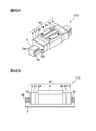
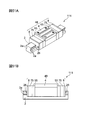
- 1A and 1B are an external view and a side view of the linear guide device of the first embodiment.
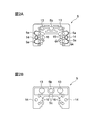
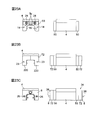
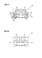
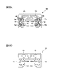
- 2A and 2B are a front view and a rear view of the end cap in the first embodiment.
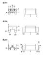
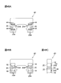
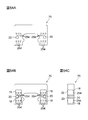
- 3A, 3B, and 3C are a front view, a side view, and a rear view of the lubricant container according to the first embodiment.
- 4A and 4B are a cross-sectional view and a side view of the lubricant container in the first embodiment.
- the dotted line in FIG. 4B has shown the internal structure of the lubricant container.
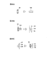
- 5A, 5B, 5C, and 5D are a side view, a front view, and a side view and a front view, respectively, of one lid of the lubricant container in the first embodiment.
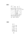
- FIG. 6A and 6B are views showing a state in which the lubricant container in the first embodiment is attached to the end cap, that is, a sectional view taken along the line 6A-6A in FIG. 2A and a partially enlarged view of FIG. 6A.
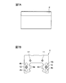
- 7A and 7B are a side view of the slider main body and a diagram showing an end face of the slider main body in the first embodiment.
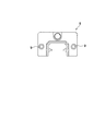
- FIG. 8 is a view showing a side seal in the first embodiment.
- FIG. 9A to FIG. 9C are diagrams sequentially illustrating the state of assembling the slider in the first embodiment, that is, a diagram illustrating an end surface and a side surface of the slider.
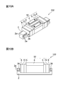
- 10A and 10B are an external view and a side view of the linear guide device of the second embodiment.
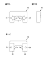
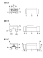
- 11A, 11B, and 11C are a front view, a side view, and a rear view of the lubricant container in the second embodiment.
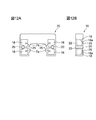
- 12A and 12B are a cross-sectional view and a side view of the lubricant container in the second embodiment.
- the dotted line in FIG. 12B has shown the internal structure of the lubricant container.
- FIG. 13A and FIG. 13B are views showing the lubricating member held in the lubricant container in the second embodiment and a view showing the state where the lubricant container is attached to the end cap, that is, corresponding to FIG. 6A of the first embodiment. It is sectional drawing.
- FIG. 14C are views sequentially showing the state of assembling the slider in the second embodiment, that is, a view showing an end face and a side face of the slider.
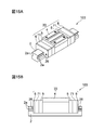
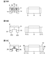
- 15A and 15B are an external view and a side view of the linear guide device according to the third embodiment.
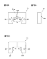
- 16A, 16B, and 16C are a front view, a side view, and a rear view of the lubricant container in the third embodiment.
- 17A, 17B, and 17C are a cross-sectional view, a side view, and a cross-sectional view showing a state in which the lubricant member is held in the lubricant container according to the third embodiment.
- the dotted line in FIG. 17B has shown the internal structure of the lubricant container.
- 18C are views sequentially showing the state of assembling the slider in the third embodiment, that is, a view showing an end face and a side face of the slider.
- 19A and 19B are an external view and a side view of the linear guide device of the fourth embodiment.
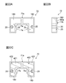
- 20A and 20B are a front view and a rear view of the end cap in the fourth embodiment.
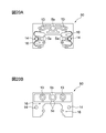
- 21A, 21B, and 21C are a front view, a side view, and a rear view of the lubricant container in the fourth embodiment.
- 22A, 22B, and 22C are a cross-sectional view, a side view, and a cross-sectional view showing a state in which the lubricant member is held in the fourth embodiment.
- FIG. 22B has shown the internal structure of the lubricant container.
- FIG. 23A to FIG. 23C are views sequentially showing the state of assembling the slider in the fourth embodiment, that is, a view showing an end face and a side face of the slider.
- 24A and 24B are an external view and a side view of the linear guide device of the fifth embodiment.
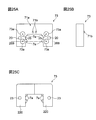
- 25A, 25B, and 25C are a front view, a side view, and a rear view of the lubricant container in the fifth embodiment.
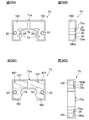
- 26A, FIG. 26B, FIG. 26C and FIG. 26D are a sectional view, a side view, a sectional view showing a state of holding a lubricating member in the fifth embodiment, and a sectional view taken along 26B-26B in FIG. 25A.
- FIG. 26B shows the internal structure of the lubricant container.
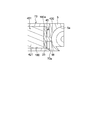
- FIG. 27 is a view showing a state in which the lubricant container in the fifth embodiment is attached to the end cap, that is, a view corresponding to FIG. 6A.
- FIG. 28A to FIG. 28C are views sequentially showing the state of assembling the slider in the fifth embodiment, that is, a view showing an end face and a side face of the slider.
- 29A and 29B are an external view and a side view of the linear guide device of the sixth embodiment.
- 30A, 30B, and 30C are a cross-sectional view, a side view, and a cross-sectional view showing a state in which the lubricant member is held according to the sixth embodiment.
- FIG. 31A to FIG. 31C are views sequentially showing the state of assembling the slider in the sixth embodiment, that is, a view showing an end face and a side face of the slider.
- 32A and 32B are an external view and a side view of the linear guide device of the seventh embodiment.
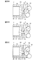
- FIG. 33A, FIG. 33B and FIG. 33C are views showing a state where the lubricant container in the seventh embodiment is attached to the end cap, a view showing how the lubricant member is deformed, and a view showing how the deformed lubricant member is restored. It is.
- FIG. 31A to FIG. 31C are views sequentially showing the state of assembling the slider in the sixth embodiment, that is, a view showing an end face and a side face of the slider.
- 32A and 32B are an external view and a side view of the linear guide device of the seventh embodiment.
- FIG. 33A, FIG. 33B and FIG. 33C are views showing a state where the lubricant container in the seventh embodiment is attached
- FIG. 34 is a rear view of the lubricant container according to the seventh embodiment, and shows a state in which the lubricating member and the pressing member are accommodated in the recess.
- FIG. 35A to FIG. 35C are views sequentially showing the state of assembling the slider in the seventh embodiment, that is, a view showing an end face and a side face of the slider.
- FIG. 36A, FIG. 36B, and FIG. 36C are views showing a state where a lubricant container is attached to an end cap, a view showing a state where a lubricant member is deformed, and a deformed lubricant member are restored in a modification of the seventh embodiment. It is a figure which shows a mode.
- FIG. 37A and 37B are an external view and a side view of the linear guide device of the eighth embodiment.
- 38A, 38B, and 38C are views showing a state where the lubricant container according to the eighth embodiment is attached to the end cap, a view showing a state where the lubricant member is deformed, and a view showing a state where the deformed lubricant member is restored. It is.
- FIG. 39A to FIG. 39C are views sequentially showing the state of assembling the slider in the eighth embodiment, that is, a view showing an end face and a side face of the slider.
- FIG. 40C are views showing a state in which the lubricant container is attached to the end cap in the modification of the eighth embodiment, a view showing how the lubricant member is deformed, and a deformed lubricant member is restored. It is a figure which shows a mode.
- 41A and 41B are an external view and a side view of the linear guide device of the ninth embodiment.
- FIG. 42 is a diagram illustrating a state in which the lubricant container according to the ninth embodiment is attached to the end cap.
- FIG. 43A to FIG. 43C are views sequentially showing the state of assembling the slider in the ninth embodiment, that is, a view showing an end face and a side face of the slider.
- FIG. 44 is a diagram illustrating a state in which the lubricant container is attached to the end cap in the modification of the ninth embodiment.
- 45A and 45B are an external view and a side view of the linear guide device of the tenth embodiment.
- FIG. 46 is a diagram illustrating a state in which the lubricant container according to the tenth embodiment is attached to the end cap.
- 47A and 47B are a front view and a rear view of the end cap in the tenth embodiment.
- 48A, 48B, and 48C are a front view, a rear view, and a side view of the lubricant container in the tenth embodiment.
- the dotted line in FIG. 48C has shown the internal structure of the lubricant container.
- 49A to 49C are diagrams sequentially illustrating the state of assembling the slider in the tenth embodiment.
- 50A to 50C are views sequentially illustrating how the slider is assembled in the tenth embodiment, that is, a diagram illustrating an end surface and a side surface of the slider.
- 51A and 51B are an external view and a side view of the linear guide device of the eleventh embodiment.
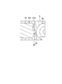
- 52A and 52B are a diagram illustrating a state in which the lubricant container according to the eleventh embodiment is attached to the end cap, and a partial enlarged view of FIG. 52A.
- 53A and 53B are a front view and a rear view of the end cap in the eleventh embodiment.
- FIG. 54A, 54B, and 54C are a front view, a rear view, and a side view of the lubricant container in the eleventh embodiment.
- the dotted line in FIG. 54C shows the internal structure of the lubricant container.
- FIG. 55A and FIG. 55B are diagrams sequentially illustrating the state of assembling the slider in the eleventh embodiment.
- FIG. 56A to FIG. 56C are views sequentially showing the state of assembling the slider in the eleventh embodiment, that is, a view showing an end face and a side face of the slider.
- a linear guide device 101 according to this embodiment shown in FIG. 1 is suitable for a numerically controlled machine tool, a numerically controlled measuring machine, and the like, and includes a guide rail 2 and a slider 31 that can move along the guide rail 2.
- the guide rail 2 is formed of a substantially square member, and two rolling grooves 2a extending in the longitudinal direction are formed on both side surfaces thereof.
- the slider 31 includes a slider body 4, an end cap 5, a lubricant container 7, and a side seal 8 that are attached in order from the slider body 4 side to the longitudinal direction of the slider body 4, that is, the left and right ends in FIG. 1B. Consists of.
- the slider body 4 is made of a metal member that extends in the longitudinal direction of the guide rail 2 and has a substantially U-shaped cross section, and is straddled over the guide rail 2.
- the portion of the slider body 4 facing the both side surfaces of the guide rail 2, that is, the inner surface of the leg portions on both sides, is a roller extending in the longitudinal direction facing the rolling groove 2a of the guide rail 2.
- Two moving grooves 4a are formed.
- the rolling groove 4a of the slider body 4 and the rolling groove 2a of the guide rail 2 form a rolling path of a rolling element (not shown).
- the rolling path is loaded with a plurality of balls as rolling elements.
- the leg portions on both sides of the slider body 4 penetrate through the slider body 4 in the longitudinal direction, that is, in the direction perpendicular to the paper surface of FIG. Has been. Further, two screw holes 11 and 12 are formed in each end face of the slider body 4.
- the end cap 5 is a resin member and has a substantially U shape as shown in FIG.
- the direction change path 5a communicates the rolling path and the return path 4b, and has a semicircular arc shape as shown in FIG. 6A.
- circular through holes 13 and 14 are formed in the end cap 5 at positions facing the screw holes 11 and 12 of the slider body 4, respectively.
- the end cap 5 is not limited to resin, but may be made of metal.
- the side seal 8 is a substantially U-shaped resin or rubber plate member as shown in FIG. 8, and has a shape straddling both side surfaces and the upper surface of the guide rail 2. With the side seal 8 having such a shape, when the slider 31 is linearly moved on the guide rail 2, foreign matters such as dust, dust and dirt adhering to both side surfaces and the upper surface of the guide rail 2 can be removed. it can.
- the side seal 8 is formed with circular through holes 9 at positions facing the screw holes 12 of the slider body 4.
- the oil supply device for a linear guide device supplies a lubricant into the slider 31 and includes an end cap 5, a lubricant container 7, and a lubricant member 40 described later.
- the lubricant container 7 is for holding the lubricating member 40, and is a resin thick plate member having substantially the same outer shape as the end cap 5, and has a substantially U-shape as shown in FIG. Yes.
- a recess that forms a substantially cubic space on the back surface of the lubricant container 7, that is, on the outer surface in the longitudinal direction of the slider 31, at a position facing the four through holes 16 of the end cap 5. 18 are provided.
- cylindrical portions 19 are integrally formed on the front surface of the lubricant container 7 at positions facing the four recesses 18 and facing the four through holes 16 of the end cap 5. Has been.
- FIG. 4A a recess that forms a substantially cubic space on the back surface of the lubricant container 7, that is, on the outer surface in the longitudinal direction of the slider 31, at a position facing the four through holes 16 of the end cap 5.
- cylindrical portions 19 are integrally formed on the front surface of the lubricant container 7 at positions facing the four recesses 18 and facing the four through
- the cylindrical portion 19 extends in the longitudinal direction of the slider 31, that is, rightward in FIG. 6A, and has a cylindrical shape that fits into the through hole 16 of the direction change path 5 a in the end cap 5. is doing.
- the circular opening in the cylindrical portion 19, that is, the hollow portion passes through the bottom surface 18 a of the opposing recess 18.
- circular through holes 20 are respectively formed at positions facing the two screw holes 12 of the slider body 4. Further, on the inner side surfaces of the leg portions on both sides of the lubricant container 7, a lip portion 7 a provided in accordance with the shape of the rolling groove 2 a of the guide rail 2 in order to prevent foreign matter from entering the slider 31. Is provided.
- a lubricating member 40 impregnated with a lubricant is held in the recess 18 of the lubricant container 7.
- the lubricating member 40 includes a second lubricating member 42 made of a porous molded body containing a large amount of a lubricant, and a first lubricating member 41 made of a porous molded body having a higher density than the second lubricating member 42. ing.
- the second lubricating member 42 has a substantially cubic shape that fits into the recess 18.
- the first lubricating member 41 has a substantially plate shape that fits into the recess 18, and is disposed on the bottom surface 18 a of the recess 18.
- the first lubricating member 41 is integrally formed with a columnar protrusion 43 that fits into the circular opening of the cylindrical portion 19 of the lubricant container 7. That is, the lubricating member 40 has a substantially cubic shape that fits into the recess 18 as a whole, and fills the space formed by the recess 18 and the cylindrical portion 19 of the lubricant container 7 without a gap. As shown in FIG. 3C, the recess 18 holding the lubricating member 40 is sealed with a lid 22 attached from the back side of the lubricant container 7. As shown in FIG.
- the lid 22 is made of the same resin plate member as the lubricant container 7, and has a rectangular shape for sealing the two concave portions 18 of the lubricant container 7 at a time.
- a circular through hole 23 is formed in the lid 22 at a position facing the through hole 20 of the lubricant container 7.
- the cylinder of the lubricant container 7 is inserted into the through hole 16 of the direction changing path 5a of the end cap 5.
- the shape part 19 can be fitted.
- the cylindrical part 19 of the lubricant container 7 and the protrusion 43 of the lubricating member 40 fitted into the circular opening of the cylindrical part 19 can be exposed to the direction change path 5a.
- the length of the cylindrical portion 19 of the lubricant container 7 and the protruding portion 43 of the lubricating member 40 in the longitudinal direction of the slider body 4, that is, the left-right direction in FIG. 5 is designed so that no step is formed between the five direction change paths 5a and the rolling grooves.
- front end surface of the cylindrical part 19 of the lubricant container 7 and the front end surface of the protrusion part 43 of the lubricating member 40 are curved shapes along the rolling groove of the direction change path 5a of the end cap 5 as shown in FIG. 6B. Each is processed.
- the lubricant container 7 is previously sealed by inserting the lubricating member 40 into each recess 18 and attaching the lid 22 from the back side.
- Procedure 1 As shown in FIG. 9A, the end caps 5 are arranged on both ends of the slider body 4 in the longitudinal direction so that the surfaces on which the direction change paths 5a are formed, that is, the front faces. Then, the screw 24 is fixed to the screw hole 11 of the slider body 4 through the through hole 13 of the end cap 5. The through hole 13 and the screw hole 11 are not shown in FIG. Thereby, the attachment of the end cap 5 to the slider body 4 is achieved.
- Procedure 2 As shown in FIG. 9B, the lubricant container 7 is attached to each end cap 5 from the outside in the longitudinal direction of the slider body 4 with the surface on which the cylindrical portion 19 is formed, that is, the front facing. The cylindrical portion 19 is not shown in FIG. At this time, the cylindrical portion 19 of the lubricant container 7 is inserted into each through hole 16 of the end cap 5. Thereby, positioning of the lubricant container 7 with respect to the end cap 5 is achieved.
- Procedure 3 As shown in FIG. 9C, side seals 8 are arranged on the lubricant containers 7 from the outside in the longitudinal direction of the slider body 4. Then, the screw 26 is passed through the through hole 9 of the side seal 8, the through hole 23 of the lid 22 of the lubricant container 7, the through hole 20 of the lubricant container 7, and the through hole 14 of the end cap 5 in order. Fix to the screw hole 12. The through holes 9 and 20 and the screw hole 12 are not shown in FIG. Thereby, attachment of the lubricant container 7 and the side seal 8 to the slider body 4 is achieved.
- the slider 31 can be easily assembled by the above assembly procedure.
- the lubricant container 7 can be positioned with respect to the end cap 5 by inserting the cylindrical portions 19 of the lubricant container 7 into the four through holes 16 of the end cap 5 as described above. it can.
- the lubricant container 7 can be easily fixed to the slider body 4 together with the side seal 8 with the common screw 26.
- the lubricant members 40 are respectively held in the four recesses 18 of the lubricant container 7 as described above, the four lubricant members 40 can be handled by the lubricant container 7 at a time. For this reason, not only the assembly of the slider 31 is facilitated, but also the maintenance of the slider 31 is facilitated. Further, since the lubricating members 40 can be handled individually, the slider 31 can be supplied with oil evenly.
- the tip of the cylindrical portion 19 of the lubricant container 7 and the tip of the protrusion 43 of the lubricant member 40 are connected to the direction change path 5a of the end cap 5 as shown in FIG.
- the through hole 16 is exposed inside, and a curved surface is formed in the through hole 16 along the rolling groove of the direction changing path 5a. More specifically, the distal end surface of the cylindrical portion 19 of the lubricant container 7 and the distal end surface of the protrusion 43 of the lubricating member 40 form a single curved surface together with the rolling groove of the direction changing path 5a.
- the tip of the cylindrical portion 19 of the lubricant container 7 and the tip of the protrusion 43 of the lubricant member 40 form a curved surface along the rolling groove of the direction change path 5a, so that A moving body can roll smoothly in the direction change path 5a. Therefore, unlike the prior art, the rolling element does not collide with the lubricating member 40, the lubricating member 40 is broken, and the fragments do not enter the direction change path 5a and the rolling element as foreign matter. . Further, unlike the prior art, there is a step between the direction change path 5a and the lubricating member 40, and there is no possibility that the rolling element collides with the step and runs around. Accordingly, it is possible to prevent the rolling element and the direction change path 5a from being damaged, and it is possible to prevent the slider 31 from being broken or malfunctioning.
- the lubricating member 40 includes the second lubricating member 42 made of a porous molded body and the first lubricating member 41 made of a porous molded body having a higher density than the second lubricating member 42. Yes. For this reason, the amount per unit volume of the first lubricating member 41 that can hold the lubricant is smaller than that of the second lubricating member 42. With such a configuration, the second lubricating member 42 can function as a holding portion that holds the lubricant.
- the first lubricating member 41 applies an appropriate amount of lubricant to the rolling elements while preventing the lubricant held by the second lubricating member 42 from flowing into the direction change path 5a of the end cap 5. It can function as an application part. Therefore, a large amount of lubricant can be prevented from being consumed in a short period of time, and refueling can be performed stably for a long period of time.
- the material of the 1st, 2nd lubrication members 41 and 42 is not restricted to the porous molded object from which the density differs as mentioned above.
- the amount per unit volume that the first lubricating member 41 can hold the lubricant may be smaller than that of the second lubricating member 42, and the first and second lubricating members 41 and 42 may be made of different materials.
- the first lubricating member 41 may be formed of a porous molded body, and the second lubricating member 42 may be configured to fill the concave portion 18 of the lubricant container 7 with a lubricant such as grease or lubricating oil.
- the oil supply device for a linear guide device includes an end cap 5, a lubricant container 70, and a lubricant member 400.
- the lubricating member 400 held in the concave portion 18 of the lubricant container 70 replaces the protrusion 43 of the lubricant member 40 in the first embodiment, ie, the inner side in the longitudinal direction of the slider 30, that is, FIG.
- a protrusion 430 that extends to the right of 13 ⁇ / b> A and protrudes outward from the circular opening 25 of the lubricant container 70 is formed integrally with the first lubricating member 410. As shown in FIG. 13B, the protrusion 430 has a cylindrical shape that fits into the circular opening 25 of the lubricant container 70 and the through hole 16 of the end cap 5.
- the protruding portion of the lubricating member 400 is formed in the through hole 16 of the direction changing path 5a of the end cap 5.
- 430 can be fitted.
- the protrusion part 430 of the lubricating member 400 can be exposed in the direction change path 5a.
- the length of the protrusion 430 of the lubricating member 400 in the longitudinal direction of the slider body 4, that is, the left-right direction in FIG. 13B is between the protrusion 430 and the rolling groove of the direction changing path 5 a of the end cap 5. It is designed so that there is no step.
- the front end surface of the projection part 430 of the lubricating member 400 is processed into the curved surface shape along the rolling groove of the direction change path 5a of the end cap 5, as shown to FIG. 13B.
- the lubricant container 70 is sealed in advance by inserting the lubricating member 400 into each recess 18 and attaching the lid 22 from the back side.
- Procedure 1 The procedure is the same as the procedure 1 of the assembling procedure of the slider 31 in the first embodiment. See FIG. 14A.
- Procedure 2 As shown in FIG. 14B, the lubricant container 70 is attached to each end cap 5 from the outside in the longitudinal direction of the slider body 4 with the surface where the circular opening 25 is formed, that is, the front facing. The circular opening 25 is not shown in FIG. At this time, the protrusions 430 of the lubricating member 400 are inserted into the through holes 16 of the end cap 5. Thereby, the positioning of the lubricant container 70 with respect to the end cap 5 is achieved.
- Procedure 3 The procedure is the same as the procedure 3 of the assembling procedure of the slider 31 in the first embodiment. See Figure 14C.
- the slider 32 can be easily assembled by the above assembly procedure.
- the lubricant container 70 can be positioned with respect to the end cap 5 by inserting the protrusions 430 of the lubricating member 400 into the four through holes 16 of the end cap 5 as described above. For this reason, there can exist an effect similar to the said 1st Embodiment.
- the tip of the protrusion 430 of the lubricating member 400 is exposed from the through hole 16 in the direction change path 5a of the end cap 5 as shown in FIG.
- a curved surface is formed in 16 along the rolling groove of the direction change path 5a. More specifically, the tip end surface of the protrusion 430 of the lubricating member 400 forms a single curved surface together with the rolling groove of the direction changing path 5a.
- the cylindrical portion 19 has a processing accuracy due to the processing accuracy of the cylindrical portion 19.
- a rolling element can roll the inside of the direction change path 5a more smoothly. Therefore, it is possible to effectively prevent damage to the rolling elements and the direction change path 5a, and it is possible to effectively prevent failure and malfunction of the slider 32.
- the lubricating member 400 in the present embodiment includes the second lubricating member 42 made of a porous molded body and the first lubricating made of a porous molded body having a higher density than the second lubricating member 42. It is comprised with the member 410. FIG. For this reason, as in the first embodiment, the refueling can be stably performed for a long time.
- the through hole 16 of the direction changing path 5a of the end cap 5 is circular, and in order to correspond to this, the cylindrical portion 19 of the lubricant container 7 is used in the first embodiment.
- the protrusion 43 of the lubricating member 40 is cylindrical.
- the lubricant container 70 is provided with the circular opening 25, and the protrusion 430 of the lubricating member 400 has a cylindrical shape.
- the present invention is not limited to this, and the through holes 16 of the direction changing path 5a may be rectangular, for example, and the parts of the lubricant containers 7 and 70 and the lubricating members 40 and 400 may be configured so as to correspond thereto.
- the lubricant containers 7 and 70 include four lubricating members 40 and 400 corresponding to the four through holes 16 of the direction changing path 5 a of the end cap 5.
- the present invention is not limited to this.
- two lubrication members having two protrusions 43 and 430 may be prepared, and a lubricant container having two recesses for holding the two lubrication members may be configured.
- the lubricant containers 7 and 70 and the lid 22 are both made of resin, but are not limited thereto and may be made of metal.
- the oil supply device for a linear guide device includes an end cap 5, a lubricant container 71, and a lubricant member 401.
- the lubricant container 71 in the present embodiment is the front surface of the lubricant container 71, that is, the inner surface in the longitudinal direction of the slider 33, and at the center position of the trunk portion 71a of the lubricant container 71.
- Two substantially prismatic protrusions 71b that can be fitted into two recesses 5c of the end cap 5 described later are provided.
- the lubricant container 71 is provided with two recesses 180 as shown in FIG. 17 instead of the recesses 18 of the lubricant container 70 in the second embodiment.
- the concave portion 180 has an L-shape that connects two adjacent concave portions 18 of the lubricant container 70 in the second embodiment and extends to the center position of the body portion.
- the same number of circular openings 25 as the lubricant container 70 in the second embodiment are provided at the same position.
- the second lubricating member 421 of the lubricating member 401 has a substantially prismatic shape with an L-shaped cross section so as to fit into the concave portion 180 of the lubricant container 71.
- the first lubricating member (not shown) has an L-shaped substantially plate shape that fits into the recess 180, and is disposed on the bottom surface 180 a of the recess 180.
- the first lubrication member is provided with two projections similar to the projections 430 of the first lubrication member 410 in the second embodiment so as to fit into the circular opening 25 of the lubricant container 71. ing. As shown in FIG.
- the recess 180 holding the lubricating member 401 having such a configuration is sealed with a lid 220 attached from the back side of the lubricant container 71.
- the lid 220 in the present embodiment has an L shape in accordance with the concave portion 180 of the lubricant container 71.
- the end cap 5 is formed with a screw hole 5b for inserting a grease nipple at the center position of the body portion, and two recesses 5c are formed around the screw hole 5b.
- the lubricant container 71 can be positioned with respect to the end cap 5.
- Procedure 1 It is the same as Procedure 1 of the assembly procedure of the slider 32 in the second embodiment. See Figure 18A.
- Procedure 2 As shown in FIG. 18B, the lubricant container 71 is attached to each end cap 5 from the outside in the longitudinal direction of the slider body 4 with the surface on which the circular opening 25 is formed, that is, the front facing. At this time, the protrusions 71 b of the lubricant container 71 are fitted into the respective recesses 5 c of the end cap 5, and the protrusions of the lubricant member 401 are inserted into the respective through holes 16 of the end cap 5. Thereby, the positioning of the lubricant container 71 with respect to the end cap 5 is achieved.
- Procedure 3 The procedure is the same as the procedure 3 of the assembling procedure of the slider 32 in the second embodiment. See Figure 18C.
- the slider 33 can be easily assembled, and the same effect as the second embodiment can be obtained.
- the lubricant container 71 in step 2, is positioned with respect to the end cap 5 using the protrusion 71b of the lubricant container 71 harder than the protrusion in addition to the protrusion of the lubricant member 401. For this reason, it is possible to effectively prevent the lubricant container 71 from being displaced relative to the end cap 5 after positioning.
- the protrusion 71 b is provided in a central position of the body portion 71 a of the lubricant container 71. For this reason, in the procedure 2, the protrusion 71b can be easily fitted in the recess 5c of the end cap 5, and the positioning of the lubricant container 71 with respect to the end cap 5 can be performed more easily.
- the slider 33 assembled based on the above assembly procedure can achieve the same effects as those of the second embodiment.
- the concave portion 180 of the lubricant container 71 in the present embodiment extends in an L shape from the leg portion of the lubricant container 71 to the center position of the trunk portion 71a, and therefore, compared with the first and second embodiments.
- the large lubricating member 401 holding a large amount of lubricant can be held. For this reason, refueling can be performed stably for a longer period of time, and the life of the slider 33 can be extended.
- the oil supply device for a linear guide device includes an end cap 50, a lubricant container 72, and a lubricant member 402.
- the end cap 50 in the present embodiment is adjacent to the through hole 16 provided in each direction changing path 5a in the end cap 5 of the third embodiment as viewed from the slider body 4 side. It is set as the structure with which only one of the suitable two direction change paths 5a is equipped. With this configuration, when the end cap 50 is attached to both ends of the slider body 4, it can be attached to both ends in common.
- the through-hole 16 is provided in two direction change paths 5 a that are located diagonally when viewed from the slider body 4 side among the four direction change paths 5 a of the end cap 50. It has been.
- the lubricant container 72 in the present embodiment has circular openings 25 provided at two locations on both leg portions in the lubricant container 71 of the third embodiment. Each leg is provided with one place so as to face the through hole 16.
- the two protrusions provided on the first lubricating member in the third embodiment are fitted into the circular opening 25 of the lubricant container 72. One place is provided to match.
- the slider 34 in the present embodiment can be easily assembled by the same assembling procedure as in the third embodiment, and the same effects as in the third embodiment can be obtained. See FIGS. 23A-23C.
- only one protrusion is provided on the first lubricating member, that is, the portion where the lubricant is applied to the rolling elements is limited to one for each lubricating member 402.
- refueling can be performed stably for a long period of time, and the life of the slider 34 can be maximized.
- the oil supply device for a linear guide device includes an end cap 5, a lubricant container 73, and a lubricant member 401.
- the lubricant container 73 in the present embodiment is a front surface of the lubricant container 73, that is, a surface on the inner side in the longitudinal direction of the slider 35, and is circular at a position facing each circular opening 25.
- Recesses 73a are respectively provided.
- the circular recess 73 a is a recess for fitting an O-ring 45 described later, and is concentric with the circular opening 25 and larger in diameter than the circular opening 25.
- Procedure 2 The O-ring 45 is fitted into each circular recess 73a of the lubricant container 73. See FIG. Then, as shown in FIG. 28B, the lubricant container 73 is attached to each end cap 5 from the outside in the longitudinal direction of the slider body 4 with the O-ring 45 fitted surface, that is, the front surface. The O-ring 45 is not shown in FIG. At this time, the protrusions 71 b of the lubricant container 73 are fitted into the respective recesses 5 c of the end cap 5, and the protrusions 430 of the lubricating member 401 are inserted into the respective through holes 16 of the end cap 5. Thereby, the positioning of the lubricant container 73 with respect to the end cap 5 is achieved.
- Procedure 3 The same as the procedure 3 of the assembling procedure of the slider 33 in the third embodiment. See Figure 28C.
- the slider 35 can be easily assembled, and the same effect as the third embodiment can be obtained. Further, the slider 35 assembled based on the above assembly procedure can achieve the same effects as those of the third embodiment.
- the space between the lubricant container 73 and the end cap 5 may be sealed so as to surround each circular opening 25 by the O-ring 45 fitted in each circular recess 73a of the lubricant container 73. it can. For this reason, it is possible to prevent the lubricant from leaking from between the lubricant container 73 and the end cap 5 to the outside of the slider 35. Accordingly, it is possible to prevent the periphery of the slider 35 from being contaminated with the lubricant and to prevent unnecessary consumption of the lubricant.
- the oil supply device for a linear guide device includes an end cap 5, a lubricant container 74, and a lubricant member 401.
- the lubricant container 74 in the present embodiment is one in which the lip portions 7a of the leg portions on both sides of the lubricant container 71 in the third embodiment are excluded. That is, the inner side surfaces 74a of the leg portions on both sides of the lubricant container 74 are flat surfaces without any unevenness. With this configuration, the lubricant container 74 can be inserted and straddled with respect to the guide rail 2 from the upper surface side of the guide rail 2.
- the slider 36 in the present embodiment can be easily assembled by the same assembly procedure as in the third embodiment, and the same effects as in the third embodiment can be achieved. See FIGS. 31A-31C.
- the lubricant container 74 since the lubricant container 74 does not have the lip portion on the inner side surfaces 74a of the leg portions on both sides as described above, it can be inserted into and removed from the guide rail 2 from the upper surface side. Therefore, when the slider 36 is maintained, only the lubricant container 74 can be removed from the guide rail 2 and the lubricant member 401 can be easily replaced, and can be fitted over the guide rail 2 again.
- the lubricant members 40 and 400 to 402 made of a porous molded body impregnated with the lubricant are held in the recesses 18 and 180 of the lubricant containers 7 and 70 to 74, respectively.
- the present invention is not limited to this, and a configuration may be adopted in which lubricants such as grease and lubricating oil are held in the recesses 18 and 180 of the lubricant containers 7 and 70 to 74.
- the lubricant may be filled in the space formed by the concave portion 18 and the cylindrical portion 19 of the lubricant container 7.
- a porous molded body impregnated with a lubricant is used as the lubricating members 40, 400 to 402.
- the present invention is not limited to this, and the lubricating members 40, 400 to 402 can be elastically deformable porous.
- a molded body (hereinafter referred to as “porous elastic body”) impregnated with a lubricant can also be used.
- a synthetic resin specifically, polyethylene (PE), polypropylene (PP), polyamide (PA), or polyacetal (POM) having high chemical resistance is used as the material for the lubricant containers 7 and 70 to 74.
- the end caps 5 and 50 are preferably made of elastic POM as a material so as to be easily attached to the slider body 4. For this reason, the lubricant containers 7 and 70 to 74 are also easily attached to the end caps 5 and 50, and the micro vibration generated intermittently when the sliders 31 to 36 pass through the joint between the guide rail 2 and the guide rail 2. It is particularly preferable to use POM as a material so that it can be absorbed.
- a polymer material in particular, a polyolefin such as polypropylene or polyethylene, as the material of the lubricating members 40, 400 to 402.
- Polyolefin has a specific gravity of 1 or less and is lightweight. Therefore, when the lubricating members 40, 400 to 402 are made of polyolefin, the load applied to the lubricant containers 7, 70 to 74 from the lubricating members 40, 400 to 402 is reduced. It is effective against this.
- Polyolefin has high insulation.
- the lubricating members 40, 400 to 402 made of polyolefin are used. Can be insulated. Therefore, it is possible to prevent the lubricant containers 7 and 70 to 74 from being damaged by static electricity.
- the cylindrical portion 19 of the lubricant container 7 exposed to the direction changing path 5a of the end cap 5 and the protrusion 43 of the lubricating member 40 are connected to the direction changing path 5a. It is flush with the groove. For this reason, even if the rolling element collides, the projection part 43 of the lubricating member 40 is not destroyed. Since the POM has elasticity as described above, if the lubricating member 40 is made of POM, such an effect can be maximized and the lubricating member 40 can be well protected. This also applies to the above-described embodiments other than the first embodiment.
- lubricating members 40, 400 to 402 animal hair such as wool, aramid, glass, cellulose, nylon, polyester, polyether, polyolefin, rayon, etc. can be used.
- animal hair such as wool, aramid, glass, cellulose, nylon, polyester, polyether, polyolefin, rayon, etc.
- the lubricating members 40 and 400 to 402 can be used as felt.
- the oil supply device for a linear guide device includes an end cap 5, a lubricant container 7, and a lubricating member 151.
- the lubricating member 151 in the present embodiment is formed integrally with the thick plate portion 151a and the thick plate portion 151a that are fitted to the bottom surface of the concave portion 18 of the lubricant container 7. It consists of a protrusion 211 that fits into the hollow part of the cylindrical part 19 of the container 7.
- the thick plate portion 151a and the protruding portion 211 are made of a porous elastic body impregnated with a lubricant.
- the length and shape of the protrusion 211 are the same as those of the protrusion 43 of the lubricating member 40 in the first embodiment.
- the lubricating member 151 is inserted into the recess 18 of the lubricant container 7, and then the pressing member 51 is further inserted to fix the position in the recess 18.
- the holding part 51 is a substantially square cylindrical member that is fitted into the side wall of the recess 18 and is made of a porous molded body.
- the concave portion 18 into which the lubricating member 151 and the pressing member 51 are inserted is filled with the lubricant 49 without any gap, and the lid 22 is attached from the back side of the lubricant container 7 and sealed.
- the material of the holding part 51 is not limited to the porous molded body.
- the linear guide device 107 can easily assemble the slider 37 by the same assembly procedure as that of the first embodiment, and can achieve the same effects as those of the first embodiment. it can. See FIGS. 35A-35C.
- the lubricating member 151 is made of a porous elastic body. For this reason, as shown in FIG. 33A, when the rolling element 52 traveling on the direction change path 5 a comes into contact with the tip surface of the protrusion 211 of the lubricating member 151 and the tip surface receives a force from the rolling element 52, lubrication is performed.
- the member 151 can be elastically deformed as shown in FIG. 33B. Specifically, the thick plate portion 151 a of the lubricant member 151 is bent outward in the longitudinal direction of the slider 37, that is, leftward in FIG. 33B, and the projection 211 is pushed into the cylindrical portion 19 of the lubricant container 7.
- the holding part 51 is made of a porous molded body. For this reason, even when the lubricant 49 in the concave portion 18 of the lubricant container 7 decreases with the oil supply to the slider 37 and the lubricant 49 and the lubricant member 151 cannot be in direct contact with each other, the posture of the slider 37 is affected. The lubricant 49 can be guided to the lubricating member 151 via the holding part 51. For this reason, oil supply to the slider 37 can be continued for a longer period of time until the lubricant 49 in the recess 18 runs out.
- the lubricating member 151, the pressing component 51, and the lubricant 49 in the present embodiment can also be applied to the linear guide device 102 in the second embodiment. See FIGS. 36A-36C.
- the lubricant 49 and the pressing part 51 are inserted into the recess 18 of the lubricant container 7 and then the lubricant 49 is filled without any gap.
- the present invention is not limited to this, and instead of the lubricant 49, a porous molded body impregnated with a lubricant or a porous elastic body impregnated with a lubricant may be arranged in the recess 18 without any gap. This also applies to an eighth embodiment described later.
- the linear guide device oil supply device includes an end cap 5, a lubricant container 70, and a lubricating member 152.
- the lubricating member 152 in the present embodiment extends to the thick plate portion 152a fitted to the bottom surface of the concave portion 18 of the lubricant container 70 and the slider 32 in the longitudinal direction, that is, to the right in FIG. 38A. And a projection 212 protruding outward from the circular opening 25 of the lubricant container 70.
- the thick plate portion 152a is made of a porous elastic body impregnated with a lubricant
- the protrusion 212 is made of a porous elastic body having a smaller porosity than the thick plate portion 152a.
- the length and shape of the protrusion 212 are the same as those of the protrusion 430 of the lubricating member 400 in the second embodiment.
- the lubricating member 152 is inserted into the recess 18 of the lubricant container 70, and then the pressing member 51 is further inserted to fix the position in the recess 18.
- the concave portion 18 into which the lubricating member 152 and the pressing component 51 are inserted is filled with the lubricant 49 without any gap, and the lid 22 is attached from the back side of the lubricant container 70 and sealed.
- the linear guide device 108 of the present embodiment can easily assemble the slider 38 by the same assembling procedure as in the second embodiment, and has the same effects as those in the second and seventh embodiments. Can play. See FIGS. 39A-39C.
- the thick plate portion 152a of the lubricating member 152 is made of a porous elastic body impregnated with a lubricant
- the protrusion 212 is made of a porous elastic body having a smaller porosity than the thick plate portion 152a.
- the protrusion 212 has a smaller amount per unit volume that can hold the lubricant than the thick plate 152a.
- the thick plate portion 152a can function as a holding portion that holds the lubricant.
- the protrusion 212 serves as an application unit that applies an appropriate amount of lubricant to the rolling elements while preventing the lubricant held by the thick plate portion 152a from flowing into the direction change path 5a of the end cap 5. Can function. Therefore, a large amount of lubricant can be prevented from being consumed in a short period of time, and refueling can be performed stably for a long period of time.
- the lubricating member 152, the pressing component 51, and the lubricant 49 in the present embodiment can also be applied to the linear guide device 101 of the first embodiment. See FIGS. 40A-40C.
- the material of the protrusion 212 is not limited to the porous elastic body, and may be a porous molded body having a smaller porosity than the thick plate portion 152a.
- the oil supply device for a linear guide device includes an end cap 5, a lubricant container 56, and a lubricating member 153.
- the lubricating member 153 in the present embodiment has a substantially cubic shape that fits the first lubricating member 41 in the first embodiment into the concave portion 18 of the lubricant container 56, and further the tapered protrusion 43 is tapered. It is a shape. That is, the protrusion 213 of the lubricating member 153 has a diameter that decreases from the root toward the tip. As shown in FIG. 42, the lubricant container 56 is tapered so that the hollow portion in the cylindrical portion 19 of the lubricant container 7 in the first embodiment can be fitted into the protrusion 213 of the lubricant member 153. It is a thing.
- the linear guide device 109 of the present embodiment can easily assemble the slider 39 by the same assembling procedure as in the first embodiment, and has the same effect as in the first embodiment. it can. See FIGS. 43A-43C.
- the protrusion 213 of the lubricating member 153 has a tapered shape. For this reason, an appropriate amount of lubricant can be applied to the rolling elements while preventing the lubricant from flowing into the direction changing path 5a of the end cap 5. Therefore, a large amount of lubricant can be prevented from being consumed in a short period of time, and refueling can be performed stably for a long period of time.
- the material of the lubricating member 153 is not limited to the porous molded body, and may be a porous elastic body.
- the lubrication member 153 in particular, the protrusion 213 is prevented from being worn or damaged, and the operability of the slider 39 and deterioration of the life are effectively prevented. be able to.
- the lubricating member 153 in the present embodiment can also be applied to the linear guide device 102 of the second embodiment. See FIG. In this case, the circular opening 25 of the lubricant container 70 and the through hole 16 of the end cap 5 in the second embodiment are tapered so that the protrusion 213 of the lubricating member 153 can be fitted.
- the linear guide device oil supply device includes an end cap 54, a lubricant container 57, and a lubricating member 154.
- the end cap 54 in the present embodiment is formed by arranging three circular through holes 164 extending in the longitudinal direction of the slider 40, that is, in the left-right direction in FIG. ing. Note that the diameters of the three through holes 164 are all the same.
- the direction in which the three through holes 164 are arranged that is, the direction C in FIG. 47A is inclined with respect to the direction in which the direction change path 5a extends in FIG. 47A, that is, the direction D in FIG. Since three through holes 164 are formed in each of the four direction change paths 5a of the end cap 54, the total number of through holes 164 is twelve.
- the lubricant container 57 is located at a position facing the twelve through holes 164 of the end cap 54, as shown in FIGS.
- a circular opening 254 having the same diameter as the through hole 164 is formed.
- the lubricant container 57 is the front surface of the lubricant container 57, that is, the inner surface in the longitudinal direction of the slider 40, and the circular recess 44 at a position facing each circular opening 254.
- the circular recess 44 is a recess for fitting an O-ring 58 described later, and is concentric with the circular opening 254 and has a larger diameter than the circular opening 254.
- the concave portion 18 of the lubricant container 57 having such a configuration is filled with the lubricant 49 without a gap, and the lid 22 is attached from the back side.
- the lubricating member 154 has a cylindrical shape that can be fitted into the through hole 164 of the end cap 54, and is made of a porous molded body impregnated with a lubricant.
- One end surface of the lubricating member 154 is processed into a curved surface shape along the rolling groove of the direction changing path 5a of the end cap 54, similarly to the front end surface of the protrusion 430 of the lubricating member 400 in the second embodiment. ing.
- the length of the lubrication member 154 is such that the direction change path 5a between the lubrication member 154 and the end cap 54 when the O-ring 58 is attached to the lubrication member 154 and inserted into the through hole 164 of the end cap 54, as will be described later. It is designed so that no step is formed between the rolling grooves. Specifically, the length of the lubricating member 154 is designed to be larger by the thickness of the O-ring 58 than the length of the through hole 164 of the end cap 54.
- Procedure 1 As shown in FIG. 49A, a lubricating member 154 is inserted into an O-ring 58 made of resin and having a circular cross section. Then, the O-ring 58 is disposed at the end of the lubricating member 154 opposite to the tip surface processed into the curved surface shape described above.
- Procedure 2 As shown in FIG. 49B, the lubricating member 154 fitted with the O-ring 58 is inserted into each through hole 164 of the end cap 54. Thereby, the tip of the lubricating member 154 is exposed from the through hole 164 in the direction changing path 5a of the end cap 54, and a curved surface is formed in the through hole 164 along the rolling groove of the direction changing path 5a. That is, the front end surface of the lubricating member 154 forms a single curved surface together with the rolling groove of the direction changing path 5a.
- Procedure 3 Same as Procedure 1 of the assembly procedure of the slider 32 in the second embodiment. See Figure 50A.
- Step 4 As shown in FIG. 50B, the lubricant container 57 is attached to each end cap 54 from the outside in the longitudinal direction of the slider body 4 with the surface on which the circular recess 44 is formed, that is, the front surface facing. The circular recess 44 is not shown in FIG. At this time, as shown in FIG. 49C, the O-ring 58 of the lubricating member 154 inserted into each through hole 164 of the end cap 54 is fitted into each circular recess 44 of the lubricant container 57. Thereby, the positioning of the lubricant container 57 with respect to the end cap 54 is achieved.
- Procedure 5 It is the same as the procedure 3 of the assembly procedure of the slider 32 in the second embodiment. See Figure 50C.
- the linear guide device 110 of this embodiment can easily assemble the slider 40 by the above assembling procedure, and can achieve the same effects as those of the second embodiment.
- the direction in which the three through holes 164 of the direction changing path 5a of the end cap 54 are arranged is the direction in which the direction changing path 5a extends in FIG. It is inclined with respect to the direction D in FIG. 47A.
- the lubricant can be applied to the rolling elements that travel on the direction change path 5a at three different positions in the direction in which the direction change path 5a extends, that is, in the direction perpendicular to the D direction in FIG. 47A.
- the oil supply into the slider 40 can be performed more stably.
- the number of through holes 164 in the direction changing path 5a of the end cap 54 is not limited to three.
- two or four or more through holes 164 may be provided in each direction changing path 5a, and the lubricating member 154 and the lubricant container 57 may be configured to correspond to the number of the through holes 164.
- the O-ring 58 is fitted in each circular recess 44 of the lubricant container 57. For this reason, when the rolling element traveling on the direction change path 5 a of the end cap 54 comes into contact with the tip surface of the lubricating member 154 and the tip surface receives a force from the rolling element, this force is applied by the elasticity of the O-ring 58. Can be resolved. With this configuration, it is possible to prevent wear and damage of the lubricating member 154 and dropout into the direction change path 5a, and it is possible to effectively prevent deterioration of the operability and life of the slider 40.
- the O-ring 58 fitted in each circular recess 44 of the lubricant container 57 can prevent the lubricant from leaking from the joint portion between the circular opening 254 of the lubricant container 57 and the through hole 164 of the end cap 54. . Therefore, it is possible to prevent the lubricant leaked from the joint portion from contaminating the slider 40 and its surroundings, and to prevent unnecessary consumption of the lubricant.
- the linear guide device oil supply device includes an end cap 55, a lubricant container 75, and a lubricating member 155.
- the lubricant container 75 in the present embodiment is obtained by removing the circular recess 44 from the lubricant container 57 in the tenth embodiment, as shown in FIGS. 52A and 54.
- the end cap 55 is provided with a large-diameter portion 46 at the end of each through-hole 164 on the direction changing path 5a side in the end cap 54 of the tenth embodiment.
- the large diameter portion 46 is a circular recess for accommodating a tube 47 described later, and is concentric with the through hole 164 and larger in diameter than the through hole 164.
- the lubricating member 155 has a cylindrical shape that can be fitted into the circular opening 254 of the lubricant container 75 and the through hole 164 of the end cap 55, and is made of a porous molded body impregnated with the lubricant. Become.
- the lubricating member 155 is designed to have a length that extends from the bottom surface of the concave portion 18 of the lubricant container 75 to the inside of the large diameter portion 46 of the end cap 55.
- a cylindrical tube 47 is fitted on the tip of the lubricating member 155.
- the tube 47 is made of a polymer material that can be impregnated with a lubricant and elastically deformed in the same manner as the porous molded body constituting the lubricating member 155.
- the tip of the tube 47 is processed into a shape along the rolling groove of the direction changing path 5 a of the end cap 55.
- the length of the tube 47 is designed to be slightly longer than the length of the large diameter portion 46 of the end cap 55.
- the tube 47 having such a configuration functions as an application unit that applies the lubricant 49 held by the lubricating member 75 to the rolling elements traveling on the direction change path 5 a of the end cap 55.
- Procedure 2 As shown in FIG. 55B, the lubricating member 155 fitted with the tube 47 is inserted into each through hole 164 of the end cap 55 from the back side. As a result, the tube 47 is accommodated in the large-diameter portion 46 of the through hole 164, and the tip of the tube 47 slightly protrudes into the direction change path 5 a of the end cap 55. At this time, since the tip of the tube 47 has a shape along the rolling groove of the direction changing path 5a as described above, the tube 47 slightly protrudes into the direction changing path 5a along the rolling groove.
- Procedure 3 Same as procedure 3 of the assembly procedure of the slider 40 in the tenth embodiment, that is, procedure 1 of the assembly procedure of the slider 32 in the second embodiment. See FIG. 56A.
- Procedure 4 As shown in FIG. 56B, the lubricant container 75 is attached to each end cap 55 from the outside in the longitudinal direction of the slider body 4 with the surface where the circular opening 254 is formed, that is, the front facing. The circular opening 254 is not shown in FIG. At this time, the lubricating member 155 attached to each through hole 164 of the end cap 55 is inserted into each circular opening 254 of the lubricant container 75. Thereby, positioning of the lubricant container 75 with respect to the end cap 55 is achieved.
- Procedure 5 The procedure is the same as the procedure 5 of the assembling procedure of the slider 40 in the tenth embodiment, that is, the procedure 3 of the assembling procedure of the slider 32 in the second embodiment. See Figure 56C.
- the linear guide device 111 of the present embodiment can easily assemble the slider 48 by the above assembling procedure, and can achieve the same effects as those of the tenth embodiment.
- the tube 47 is made of an elastically deformable polymer material and has high flexibility. Therefore, the lubricating member 155 to which the tube 47 is attached in the procedure 2 can be easily inserted into the through hole 164 having a small diameter provided in the end cap 55 while the tube 47 is elastically deformed.
- the tip of the tube 47 slightly protrudes into the direction change path 5a along the rolling groove of the direction change path 5a of the end cap 55 as shown in FIG. 52B.
- the lubricant can be reliably applied to the rolling elements traveling on the direction change path 5a of the end cap 55 without obstructing the traveling of the rolling elements. Since the tube 47 has high flexibility and can be elastically deformed as described above, when the rolling elements traveling on the direction change path 5a of the end cap 55 collide, the tube 47 can absorb the impact and hardly break. .
- the present embodiment is configured to apply the lubricant by bringing the cylindrical tube 47 into contact with the rolling elements traveling on the direction change path 5a of the end cap 55. For this reason, an appropriate amount of lubricant can be applied to the rolling elements while preventing the lubricant from flowing into the direction change path 5a of the end cap 55. Therefore, a large amount of lubricant can be prevented from being consumed in a short period of time, and refueling can be performed stably for a long period of time.
- the material of the tube 47 is preferably a polymer material such as polyolefin, urethane, fluororesin, or vinyl chloride, especially polyolefin.
- polyolefin has a specific gravity of 1 or less and is lightweight. Therefore, when the tube 47 is made of polyolefin, a load applied from the lubricant member 155 to the lubricant container 75 is reduced, and thus the tube 47 is effective for the lubricant container 75.
- polyolefin has high insulation as described above. Therefore, even when static electricity is generated due to friction between the direction change path 5a of the end cap 55 and the rolling elements when the slider 48 travels on the guide rail 2, the tube 47 made of polyolefin and the lubricating member 155 can be insulated. it can. For this reason, it is possible to prevent the lubricant container 75 from being damaged by static electricity.
- polyethylene is soft. For this reason, if polyethylene is used as the material of the tube 47, the lubricating member 155 attached with the tube 47 in the procedure 2 can be easily inserted through the through-hole 164 of the end cap 55. In order to give rigidity to polyethylene, it is more preferable to compound polypropylene with polyethylene.
- the oil supply device for the linear guide device of each of the above embodiments is provided at both ends of the slider body 4, but is not limited to this, and in the first to third and fifth to eleventh embodiments, one of the slider body 4 is provided. It is good also as a structure provided only in an edge part.
- the linear guide devices 101 to 111 including balls as rolling elements are shown.
- the present invention is not limited to this, and a linear guide device including rollers as rolling elements can also be configured.
Landscapes
- Engineering & Computer Science (AREA)
- General Engineering & Computer Science (AREA)
- Mechanical Engineering (AREA)
- Bearings For Parts Moving Linearly (AREA)
Abstract
Description
スライダの長手方向の端部に配置されており、前記スライダ内の転動体の転動方向を転換するための方向転換路を有するエンドキャップと、
潤滑剤を保持し、前記エンドキャップに隣接して配置された容器とからなり、
前記エンドキャップには、前記方向転換路から前記容器へ向かって延びた貫通孔が形成されており、
前記容器には、前記エンドキャップの前記貫通孔に連通する開口が形成されており、
前記潤滑剤は、前記容器の前記開口と前記エンドキャップの前記貫通孔を経て前記方向転換路内に給油されることを特徴とするリニアガイド装置用給油装置を提供する。
前記リニアガイド装置用給油装置を備えたことを特徴とするリニアガイド装置を提供する。
本発明の各実施形態に係るリニアガイド装置用給油装置を備えたリニアガイド装置を添付図面に基づいて説明する。
本明細書においては、リニアガイド装置の案内レールを水平にした状態において、案内レールの長手方向に対して水平方向へ直角に交差する方向を幅方向とし、長手方向及び幅方向に対して垂直に交差する方向を上下方向とする。また、案内レールの長手方向へ延在する上側の面、下側の面及び幅方向側の面をそれぞれ上面、下面及び側面とし、長手方向の端部側の面を端面とする。
図1に示す本実施形態のリニアガイド装置101は、数値制御工作機や数値制御測定機等に好適なものであり、案内レール2と、案内レール2に沿って移動可能なスライダ31とからなる。
案内レール2は、略四角型の部材からなり、その両側面には長手方向へ延びる転動溝2aが2本ずつ形成されている。
スライダ31は、スライダ本体4と、スライダ本体4の長手方向、即ち図1Bの左右方向の両端部に、スライダ本体4側から順に取り付けられたエンドキャップ5、潤滑剤容器7、及びサイドシール8とからなる。
斯かるスライダ本体4の転動溝4aと案内レール2の転動溝2aとは、不図示の転動体の転動路を形成している。なお、この転動路には転動体として複数のボールが装填されている。
図7Bに示すように、スライダ本体4の両側の脚部には、スライダ本体4の長手方向、即ち図7Bの紙面垂直方向へ貫通しており、断面が円形の戻し路4bが2本ずつ形成されている。また、スライダ本体4の両端面にはネジ穴11、12が2箇所ずつ形成されている。
サイドシール8は、図8に示すように略コ字状をした樹脂製又はゴム製の板部材であって、案内レール2の両側面及び上面に跨嵌する形状をしている。斯かる形状のサイドシール8により、スライダ31を案内レール2上で直線運動させた際に、案内レール2の両側面や上面に付着している塵、埃、ゴミ等の異物を除去することができる。なお、サイドシール8には、スライダ本体4のネジ穴12に対向する位置に、円形の貫通穴9がそれぞれ形成されている。
本実施形態に係るリニアガイド装置用給油装置は、スライダ31内へ潤滑剤を給油するものであり、エンドキャップ5と、潤滑剤容器7と、後述する潤滑部材40とによって構成されている。
エンドキャップ5の方向転換路5aには、図6Aに示すように、スライダ31の長手方向、即ち図6Aの左右方向へ延びる円形の貫通孔16が形成されている、即ち図2Aも参照。
潤滑剤容器7の正面には、図3Aに示すように、4つの凹部18に対向し、かつエンドキャップ5の4つの貫通孔16に対向する位置に、筒状部19がそれぞれ一体的に形成されている。筒状部19は、図6Aに示すように、スライダ31の長手方向内側、即ち図6Aの右方向へ延びており、エンドキャップ5における方向転換路5aの貫通孔16に嵌合する円筒形状をしている。筒状部19内の円形開口、即ち中空部は、対向する凹部18の底面18aを貫通している。
なお、潤滑剤容器7には、スライダ本体4の2つのネジ穴12に対向する位置に、円形の貫通穴20がそれぞれ形成されている。また、潤滑剤容器7の両側の脚部の内側面には、スライダ31内への異物の侵入を防止するために、案内レール2の転動溝2aの形状に合わせて設けられたリップ部7aが備えられている。
潤滑部材40を保持した凹部18は、図3Cに示すように、潤滑剤容器7の背面側より蓋22が取り付けられて密封される。蓋22は、図5に示すように、潤滑剤容器7と同じ樹脂製の板部材からなり、潤滑剤容器7の2つの凹部18を一度に密封するために長方形状をしている。なお、蓋22には、潤滑剤容器7の貫通穴20に対向する位置に円形の貫通穴23が形成されている。
ここで、スライダ本体4の長手方向、即ち図6の左右方向における潤滑剤容器7の筒状部19と潤滑部材40の突起部43の長さは、筒状部19及び突起部43とエンドキャップ5の方向転換路5aの転動溝との間に段差が生じないようにそれぞれ設計されている。そして、潤滑剤容器7の筒状部19の先端面及び潤滑部材40の突起部43の先端面は、図6Bに示すようにエンドキャップ5の方向転換路5aの転動溝に沿った曲面形状にそれぞれ加工されている。
なお、予め潤滑剤容器7は、各凹部18に潤滑部材40を挿入し、背面側より蓋22を取り付けて密封しておく。
この構成により、スライダ31を案内レール2上で直線運動させた際に、方向転換路5aを転動する転動体が潤滑部材40の突起部43の先端面に接触して潤滑剤を塗布されることにより、スライダ31内へ給油することができる。
図10に示す第2実施形態に係るリニアガイド装置用給油装置を備えたリニアガイド装置102について、上記第1実施形態と同様の構成については同じ符号を付して説明を省略し、異なる構成について詳細に説明する。
本実施形態に係るリニアガイド装置用給油装置は、エンドキャップ5と、潤滑剤容器70と、潤滑部材400とによって構成されている。
図13Aに示すように、潤滑剤容器70の凹部18に保持される潤滑部材400は、上記第1実施形態における潤滑剤部材40の突起部43に代えて、スライダ30の長手方向内側、即ち図13Aの右方向へ延在し潤滑剤容器70の円形開口25から外部へ突き出る突起部430が第1潤滑部材410に一体的に形成されている。突起部430は、図13Bに示すように、潤滑剤容器70の円形開口25及びエンドキャップ5の貫通孔16に嵌合する円柱形状をしている。
ここで、スライダ本体4の長手方向、即ち図13Bの左右方向における潤滑部材400の突起部430の長さは、該突起部430とエンドキャップ5の方向転換路5aの転動溝との間に段差が生じないように設計されている。そして、潤滑部材400の突起部430の先端面は、図13Bに示すようにエンドキャップ5の方向転換路5aの転動溝に沿った曲面形状に加工されている。
なお、予め潤滑剤容器70は、各凹部18に潤滑部材400を挿入し、背面側より蓋22を取り付けて密封しておく。
手順1:上記第1実施形態におけるスライダ31の組み立て手順の手順1と同様である。図14Aを参照。
手順3:上記第1実施形態におけるスライダ31の組み立て手順の手順3と同様である。図14Cを参照。
なお、潤滑剤容器7、70及び蓋22はともに樹脂製であるが、これに限られず金属製としてもよい。
図15に示す第3実施形態に係るリニアガイド装置用給油装置を備えたリニアガイド装置103について、上記第2実施形態と同様の構成については同じ符号を付して説明を省略し、異なる構成について詳細に説明する。
本実施形態に係るリニアガイド装置用給油装置は、エンドキャップ5と、潤滑剤容器71と、潤滑部材401とによって構成されている。
また、潤滑剤容器71には、上記第2実施形態における潤滑剤容器70の凹部18に代えて、図17に示すように2つの凹部180が設けられている。凹部180は、上記第2実施形態における潤滑剤容器70の隣接する2つの凹部18をつなげて胴部の中央位置まで延在させた形状、即ちL字型をしている。
なお、潤滑剤容器71には、上記第2実施形態における潤滑剤容器70と同様の円形開口25が同位置に同数設けられている。
斯かる構成の潤滑部材401を保持した凹部180は、図16Cに示すように、潤滑剤容器71の背面側より蓋220が取り付けられて密封される。なお、本実施形態における蓋220は、潤滑剤容器71の凹部180に合わせてL字型をしている。
なお、予め潤滑剤容器71は、各凹部180に潤滑部材401を挿入し、背面側より蓋220を取り付けて密封しておく。
手順1:上記第2実施形態におけるスライダ32の組み立て手順の手順1と同様である。図18Aを参照。
手順3:上記第2実施形態におけるスライダ32の組み立て手順の手順3と同様である。図18Cを参照。
図19に示す第4実施形態に係るリニアガイド装置用給油装置を備えたリニアガイド装置104について、上記第3実施形態と同様の構成については同じ符号を付して説明を省略し、異なる構成について詳細に説明する。
本実施形態に係るリニアガイド装置用給油装置は、エンドキャップ50と、潤滑剤容器72と、潤滑部材402とによって構成されている。
詳細には、本実施形態におけるエンドキャップ50は、エンドキャップ50の4つの方向転換路5aのうち、スライダ本体4側から見て対角線上に位置する2つの方向転換路5aに貫通孔16が備えられている。
図24に示す第5実施形態に係るリニアガイド装置用給油装置を備えたリニアガイド装置105について、上記第3実施形態と同様の構成については同じ符号を付して説明を省略し、異なる構成について詳細に説明する。
本実施形態に係るリニアガイド装置用給油装置は、エンドキャップ5と、潤滑剤容器73と、潤滑部材401とによって構成されている。
なお、予め潤滑剤容器73は、各凹部180に潤滑部材401を挿入し、背面側より蓋220を取り付けて密封しておく。
手順1:上記第3実施形態におけるスライダ33の組み立て手順の手順1と同様である。図28Aを参照。
手順3:上記第3実施形態におけるスライダ33の組み立て手順の手順3と同様である。図28Cを参照。
また、以上の組み立て手順に基づいて組み立てたスライダ35は、上記第3実施形態と同様の効果を奏することができる。特に、本実施形態では、潤滑剤容器73の各円形凹部73aに嵌め込まれたOリング45により、各円形開口25を取り囲むように、潤滑剤容器73とエンドキャップ5との間を密閉することができる。このため、潤滑剤が潤滑剤容器73とエンドキャップ5の間からスライダ35外へ漏洩することを防止できる。したがって、スライダ35の周辺が潤滑剤で汚染されることを防止できるとともに、潤滑剤を不必要に消費することも防止できる。
図29に示す第6実施形態に係るリニアガイド装置用給油装置を備えたリニアガイド装置106について、上記第3実施形態と同様の構成については同じ符号を付して説明を省略し、異なる構成について詳細に説明する。
本実施形態に係るリニアガイド装置用給油装置は、エンドキャップ5と、潤滑剤容器74と、潤滑部材401とによって構成されている。
ポリオレフィンは比重が1以下で軽量である。したがって、潤滑部材40、400~402をポリオレフィンで構成することにより、潤滑部材40、400~402から潤滑剤容器7、70~74へかかる負荷が小さくなるため、潤滑剤容器7、70~74に対して有効である。
また、ポリオレフィンは絶縁性が高い。したがって、スライダ31~36が案内レール2上を走行した時にエンドキャップ5、50の方向転換路5aと転動体との摩擦により静電気が生じた場合でも、ポリオレフィンで構成した潤滑部材40、400~402で絶縁することができる。このため、静電気によって潤滑剤容器7、70~74が破損してしまうことを防止することができる。
また、図6Bに示したように潤滑剤容器7の筒状部19と潤滑部材40の突起部43とを嵌合させる構成の場合、軟質であるPEを潤滑部材40の材料に用いることで、筒状部19に突起部43を嵌めやすくなるので好ましい。なお、PEに剛性をもたせるために、PEにPPをコンパウンドすることがより好ましい。
図32に示す第7実施形態に係るリニアガイド装置用給油装置を備えたリニアガイド装置107について、上記第1実施形態と同様の構成については同じ符号を付して説明を省略し、異なる構成について詳細に説明する。
本実施形態に係るリニアガイド装置用給油装置は、図33Aに示すように、エンドキャップ5と、潤滑剤容器7と、潤滑部材151とによって構成されている。
また、本実施形態では潤滑剤容器7の凹部18に潤滑部材151と押さえ部品51が挿入された後、潤滑剤49が隙間なく充填される。しかしこれに限られず、潤滑剤49の代わりに潤滑剤を含浸した多孔質成形体や潤滑剤を含浸した多孔質弾性体を凹部18に隙間なく配置する構成としてもよい。なおこのことは、後述する第8実施形態においても同様である。
図37に示す第8実施形態に係るリニアガイド装置用給油装置を備えたリニアガイド装置108について、上記第2、第7実施形態と同様の構成については同じ符号を付して説明を省略し、異なる構成について詳細に説明する。
本実施形態に係るリニアガイド装置用給油装置は、図38Aに示すように、エンドキャップ5と、潤滑剤容器70と、潤滑部材152とによって構成されている。
図41に示す第9実施形態に係るリニアガイド装置用給油装置を備えたリニアガイド装置109について、上記第1実施形態と同様の構成については同じ符号を付して説明を省略し、異なる構成について詳細に説明する。
本実施形態に係るリニアガイド装置用給油装置は、図42に示すように、エンドキャップ5と、潤滑剤容器56と、潤滑部材153とによって構成されている。
潤滑剤容器56は、図42に示すように、上記第1実施形態における潤滑剤容器7の筒状部19内の中空部を、潤滑部材153の突起部213が嵌合できるようにテーパー形状にしたものである。
また、本実施形態における潤滑部材153は、上記第2実施形態のリニアガイド装置102に適用することもできる。図44を参照。この場合、第2実施形態における潤滑剤容器70の円形開口25及びエンドキャップ5の貫通孔16を潤滑部材153の突起部213が嵌合できるようにテーパー形状とする。
図45に示す第10実施形態に係るリニアガイド装置用給油装置を備えたリニアガイド装置110について、上記第2実施形態と同様の構成については同じ符号を付して説明を省略し、異なる構成について詳細に説明する。
本実施形態に係るリニアガイド装置用給油装置は、図46に示すように、エンドキャップ54と、潤滑剤容器57と、潤滑部材154とによって構成されている。
なお、潤滑部材154の長さは、後述するように潤滑部材154にOリング58を装着してエンドキャップ54の貫通孔164に挿入した際に、潤滑部材154とエンドキャップ54の方向転換路5aの転動溝との間に段差が生じないように設計されている。具体的には、潤滑部材154の長さは、エンドキャップ54の貫通孔164の長さよりもOリング58の厚み分だけ大きく設計されている。
なお、予め潤滑剤容器57は、各凹部18に潤滑剤49を充填し、背面側より蓋22を取り付けておく。
手順1:図49Aに示すように、樹脂製で断面が円形のOリング58に潤滑部材154を挿入する。そして、潤滑部材154の上述した曲面形状に加工された先端面と反対側の端部にOリング58を配置する。
手順3:上記第2実施形態におけるスライダ32の組み立て手順の手順1と同様である。図50Aを参照。
手順5:上記第2実施形態におけるスライダ32の組み立て手順の手順3と同様である。図50Cを参照。
図51に示す第11実施形態に係るリニアガイド装置用給油装置を備えたリニアガイド装置111について、上記第10実施形態と同様の構成については同じ符号を付して説明を省略し、異なる構成について詳細に説明する。
本実施形態に係るリニアガイド装置用給油装置は、図52Aに示すように、エンドキャップ55と、潤滑剤容器75と、潤滑部材155とによって構成されている。
なお、予め潤滑剤容器75は、各凹部18に潤滑剤49を充填し、背面側より蓋22を取り付けておく。
手順1:図55Aに示すように、潤滑部材155の一端にチューブ47を装着する。
手順3:上記第10実施形態におけるスライダ40の組み立て手順の手順3、即ち上記第2実施形態におけるスライダ32の組み立て手順の手順1と同様である。図56Aを参照。
手順5:上記第10実施形態におけるスライダ40の組み立て手順の手順5、即ち上記第2実施形態におけるスライダ32の組み立て手順の手順3と同様である。図56Cを参照。
また、上記各実施形態では、転動体としてボールを備えたリニアガイド装置101~111を示しているが、これに限られず、転動体としてころを備えたリニアガイド装置を構成することもできる。
2 案内レール
31~40、48 スライダ
5、50、54、55 エンドキャップ
5a 方向転換路
16、164 エンドキャップの貫通孔
40、151~155、400~402 潤滑部材
43、211~213、430 突起部
41、410 第1潤滑部材
42、421 第2潤滑部材
49 潤滑剤
7、56、57、70~75 潤滑剤容器
18、180 潤滑剤容器の凹部
8 サイドシール
Claims (31)
- スライダの長手方向の端部に配置されており、前記スライダ内の転動体の転動方向を転換するための方向転換路を有するエンドキャップと、
潤滑剤を保持し、前記エンドキャップに隣接して配置された容器とからなり、
前記エンドキャップには、前記方向転換路から前記容器へ向かって延びた貫通孔が形成されており、
前記容器には、前記エンドキャップの前記貫通孔に連通する開口が形成されており、
前記潤滑剤は、前記容器の前記開口と前記エンドキャップの前記貫通孔を経て前記方向転換路内に給油されることを特徴とするリニアガイド装置用給油装置。 - 前記容器は、前記潤滑剤を含浸した多孔質成形体からなり突起部を有する潤滑部材を保持し、
前記潤滑部材の前記突起部は、前記容器の前記開口から突出し、前記エンドキャップの前記貫通孔に挿入されて前記方向転換路内に露呈しており、
前記潤滑部材の前記突起部の先端は、前記方向転換路の転動溝に沿って曲面を形成していることを特徴とする請求項1に記載のリニアガイド装置用給油装置。 - 前記多孔質成形体が弾性変形可能であることを特徴とする請求項2に記載のリニアガイド装置用給油装置。
- 前記容器は、前記開口の位置に筒状部を有し、
前記容器の前記開口から突出した前記潤滑部材の前記突起部が、前記筒状部内の中空部に嵌合し、
前記容器の前記筒状部が前記エンドキャップの前記貫通孔に嵌合し、前記潤滑部材の前記突起部及び前記容器の前記筒状部が前記エンドキャップの前記方向転換路内に露呈しており、
前記潤滑部材の前記突起部の先端及び前記容器の前記筒状部の先端が、前記エンドキャップの前記方向転換路の転動溝に沿って曲面を形成していることを特徴とする請求項2に記載のリニアガイド装置用給油装置。 - 前記容器の前記開口から突出した前記潤滑部材の前記突起部は、前記エンドキャップの前記貫通孔に嵌合していることを特徴とする請求項2に記載のリニアガイド装置用給油装置。
- 前記潤滑部材の前記突起部がテーパー形状であることを特徴とする請求項2に記載のリニアガイド装置用給油装置。
- 前記容器は、前記潤滑部材を保持する凹部と、前記凹部を閉塞する蓋部材とを有し、
前記凹部の底面に前記開口が形成されていることを特徴とする請求項2に記載のリニアガイド装置用給油装置。 - 前記潤滑部材は、前記凹部の底面に嵌合する板状部と、前記突起部とからなることを特徴とする請求項7に記載のリニアガイド装置用給油装置。
- 前記突起部を構成する多孔質成形体の空孔率が、前記板状部を構成する多孔質成形体の空孔率よりも小さいことを特徴とする請求項8に記載のリニアガイド装置用給油装置。
- 前記凹部に前記板状部の位置を固定するための押さえ部品を有することを特徴とする請求項8に記載のリニアガイド装置用給油装置。
- 前記押さえ部品は多孔質成形体で構成されており、
前記潤滑部材と前記押さえ部品を収容した前記凹部に、潤滑剤又は潤滑剤を含浸した多孔質成形体がさらに収容されていることを特徴とする請求項10に記載のリニアガイド装置用給油装置。 - 多孔質成形体からなる柱状の潤滑部材を有し、
前記潤滑部材は前記容器の前記開口内から前記エンドキャップの前記貫通孔内にわたって延在しており、
前記潤滑部材の一方の先端は前記方向転換路内に露呈し、前記方向転換路の転動溝に沿って曲面を形成しており、
前記容器には、前記開口の周囲に凹みが形成されており、
前記潤滑部材の他方の先端には、前記他方の先端を取り巻くように密閉部材が取り付けられており、
前記密閉部材は前記容器の前記凹みに嵌合していることを特徴とする請求項1に記載のリニアガイド装置用給油装置。 - 前記エンドキャップの前記方向転換路には、前記貫通孔が複数形成されており、
前記容器には、前記開口及び前記凹みが前記貫通孔と同数形成されており、
前記密閉部材が取り付けられた前記潤滑部材は、複数の前記貫通孔のそれぞれに配置されていることを特徴とする請求項12に記載のリニアガイド装置用給油装置。 - 多孔質成形体からなる柱状の潤滑部材を有し、
前記潤滑部材は前記容器の前記開口内から前記エンドキャップの前記貫通孔内にわたって延在しており、
前記潤滑部材の一方の先端には、潤滑剤を含浸可能で弾性変形可能な高分子材料で構成された筒状部品が取り付けられており、
前記筒状部品の先端は、前記エンドキャップの前記方向転換路の転動溝に沿った形状をしており、前記方向転換路内に露呈していることを特徴とする請求項1に記載のリニアガイド装置用給油装置。 - 前記エンドキャップの前記方向転換路には、前記貫通孔が複数形成されており、
前記容器には、前記開口が前記貫通孔と同数形成されており、
前記筒状部品が取り付けられた前記潤滑部材は、複数の前記貫通孔のそれぞれに配置されていることを特徴とする請求項14に記載のリニアガイド装置用給油装置。 - 前記容器は、前記潤滑剤を保持する凹部と、前記凹部を閉塞する蓋部材とを有し、
前記凹部の底面に前記開口が形成されていることを特徴とする請求項1に記載のリニアガイド装置用給油装置。 - 前記エンドキャップは、前記方向転換路を複数有し、
複数の前記方向転換路には、それぞれに前記貫通孔が形成されており、
前記容器は、前記凹部を、前記エンドキャップの前記貫通孔と同数備えていることを特徴とする請求項7に記載のリニアガイド装置用給油装置。 - 請求項1に記載のリニアガイド装置用給油装置を備えたことを特徴とするリニアガイド装置。
- 前記スライダは、前記容器に隣接して配置されたサイドシールを有し、
前記サイドシール、前記容器及び前記エンドキャップには、スライダ本体の長手方向の端部に形成されたネジ穴に対向する貫通穴がそれぞれ形成されており、
ネジが前記サイドシール、前記容器及び前記エンドキャップの前記貫通穴を順に通って前記スライダ本体の前記ネジ穴に取り付けられていることを特徴とする請求項18に記載のリニアガイド装置。 - 前記容器は、多孔質成形体からなり突起部を有する第1潤滑部材と、前記潤滑剤を含浸した多孔質成形体からなる第2潤滑部材とを収容し、
前記第1潤滑部材の前記突起部は、前記容器の前記開口から突出し、前記エンドキャップの前記貫通孔に挿入されて前記方向転換路内に露呈しており、前記突起部の先端は、前記方向転換路の転動溝に沿って曲面を形成しており、
前記第1潤滑部材は、前記潤滑剤を保持できる単位体積当たりの量が前記第2潤滑部材よりも小さく、
前記容器の前記開口から突出した前記第1潤滑部材の前記突起部は、前記エンドキャップの前記貫通孔に嵌合していることを特徴とする請求項1に記載のリニアガイド装置用給油装置。 - 前記容器は、前記第1潤滑部材及び前記第2潤滑部材を収容する凹部と、前記凹部を閉塞する蓋部材とを有し、
前記凹部の底面に前記開口が形成されていることを特徴とする請求項20に記載のリニアガイド装置用給油装置。 - 前記容器は、コ字状の厚板部材からなり、
前記凹部は、前記容器に2箇所設けられており、1つは前記容器の一方の脚部から胴部の中央位置にわたってL字型に延在しており、もう1つは前記容器の他方の脚部から前記胴部の中央位置にわたってL字型に延在していることを特徴とする請求項21に記載のリニアガイド装置用給油装置。 - 前記容器は、前記凹部を、前記エンドキャップの前記貫通孔と同数備えていることを特徴とする請求項21に記載のリニアガイド装置用給油装置。
- 前記エンドキャップは、前記方向転換路を複数有し、
複数の前記方向転換路には、それぞれに前記貫通孔が形成されていることを特徴とする請求項20に記載のリニアガイド装置用給油装置。 - 前記エンドキャップは、前記方向転換路を複数有し、
隣り合う2つの前記方向転換路のうちの一方のみに前記貫通孔が形成されていることを特徴とする請求項20に記載のリニアガイド装置用給油装置。 - 前記エンドキャップは、前記方向転換路を4つ有し、
4つの前記方向転換路のうち、対角線上に位置する2つの前記方向転換路に前記貫通孔が形成されていることを特徴とする請求項20に記載のリニアガイド装置用給油装置。 - 前記エンドキャップに対して前記容器の位置決めを行うために、
前記容器は、係止部を有し、
前記エンドキャップは、前記容器の前記係止部と嵌合可能な被係止部を有することを特徴とする請求項20に記載のリニアガイド装置用給油装置。 - 前記容器には、前記開口の周囲に凹みが形成されており、
前記凹みには、前記開口を取り巻くように密閉部材が配置されていることを特徴とする請求項20に記載のリニアガイド装置用給油装置。 - 前記容器は、コ字状の厚板部材からなり、
前記容器における両側の脚部の内側面が平面であることを特徴とする請求項20に記載のリニアガイド装置用給油装置。 - 請求項20に記載のリニアガイド装置用給油装置を備えたことを特徴とするリニアガイド装置。
- 前記スライダは、前記容器に隣接して配置されたサイドシールを有し、
前記サイドシール、前記容器及び前記エンドキャップには、スライダ本体の長手方向の端部に形成されたネジ穴に対向する貫通穴がそれぞれ形成されており、
ネジが前記サイドシール、前記容器及び前記エンドキャップの前記貫通穴を順に通って前記スライダ本体の前記ネジ穴に取り付けられていることを特徴とする請求項30に記載のリニアガイド装置。
Priority Applications (2)
| Application Number | Priority Date | Filing Date | Title |
|---|---|---|---|
| JP2015525241A JP6390616B2 (ja) | 2013-07-04 | 2014-07-01 | リニアガイド装置用給油装置、リニアガイド装置 |
| CN201480035473.3A CN105324585B (zh) | 2013-07-04 | 2014-07-01 | 线性导向装置用供油装置和线性导向装置 |
Applications Claiming Priority (10)
| Application Number | Priority Date | Filing Date | Title |
|---|---|---|---|
| JP2013140825 | 2013-07-04 | ||
| JP2013-140825 | 2013-07-04 | ||
| JP2014-023927 | 2014-02-11 | ||
| JP2014023927 | 2014-02-11 | ||
| JP2014-043546 | 2014-03-06 | ||
| JP2014043546 | 2014-03-06 | ||
| JP2014-045443 | 2014-03-07 | ||
| JP2014045443 | 2014-03-07 | ||
| JP2014045823 | 2014-03-10 | ||
| JP2014-045823 | 2014-03-10 |
Publications (1)
| Publication Number | Publication Date |
|---|---|
| WO2015002201A1 true WO2015002201A1 (ja) | 2015-01-08 |
Family
ID=52143774
Family Applications (1)
| Application Number | Title | Priority Date | Filing Date |
|---|---|---|---|
| PCT/JP2014/067566 Ceased WO2015002201A1 (ja) | 2013-07-04 | 2014-07-01 | リニアガイド装置用給油装置、リニアガイド装置 |
Country Status (4)
| Country | Link |
|---|---|
| JP (1) | JP6390616B2 (ja) |
| CN (1) | CN105324585B (ja) |
| TW (1) | TWI657205B (ja) |
| WO (1) | WO2015002201A1 (ja) |
Cited By (1)
| Publication number | Priority date | Publication date | Assignee | Title |
|---|---|---|---|---|
| CN105840652A (zh) * | 2015-01-12 | 2016-08-10 | 永进机械工业股份有限公司 | 一种改善滚动式线性滑轨动态特性的方法 |
Families Citing this family (3)
| Publication number | Priority date | Publication date | Assignee | Title |
|---|---|---|---|---|
| CN107687567B (zh) * | 2017-10-12 | 2023-03-28 | 重庆市灵龙自动化设备有限公司 | 一种扁平马达用自动点油机 |
| CN112228455B (zh) * | 2019-07-15 | 2023-10-31 | Thk株式会社 | 运动引导装置以及在运动引导装置中使用的润滑路径部件 |
| JP7537418B2 (ja) * | 2021-12-16 | 2024-08-21 | トヨタ自動車株式会社 | ガイド治具 |
Citations (5)
| Publication number | Priority date | Publication date | Assignee | Title |
|---|---|---|---|---|
| JPH0571442U (ja) * | 1992-03-02 | 1993-09-28 | 光洋精工株式会社 | 直動形ガイド装置 |
| JPH1078033A (ja) * | 1996-08-30 | 1998-03-24 | Nippon Seiko Kk | リニアガイド装置 |
| JP2009014177A (ja) * | 2007-07-09 | 2009-01-22 | Nippon Thompson Co Ltd | ローラ形式の直動案内ユニット |
| JP2009063059A (ja) * | 2007-09-05 | 2009-03-26 | Nippon Thompson Co Ltd | 直動転がり案内ユニット用のスライダ |
| JP2013096431A (ja) * | 2011-10-28 | 2013-05-20 | Nippon Thompson Co Ltd | 直動転がり案内ユニット |
Family Cites Families (8)
| Publication number | Priority date | Publication date | Assignee | Title |
|---|---|---|---|---|
| JP2696446B2 (ja) * | 1991-09-10 | 1998-01-14 | 株式会社ユニシアジェックス | 筒内直接噴射型噴射弁のアシストエア供給装置 |
| JPH0571443U (ja) * | 1992-03-02 | 1993-09-28 | 光洋精工株式会社 | 直動形ガイド装置 |
| CH688562A5 (de) * | 1993-08-12 | 1997-11-14 | Schaeffler Waelzlager Kg | Abstreifereinheit fuer ein Lagerelement. |
| DE4438566B4 (de) * | 1994-10-28 | 2009-04-09 | Schaeffler Kg | Linearwälzlager |
| JP4070265B2 (ja) * | 1997-07-01 | 2008-04-02 | Thk株式会社 | 直線案内装置 |
| JP4152362B2 (ja) * | 2004-07-30 | 2008-09-17 | 日本トムソン株式会社 | 転がり案内ユニット |
| TWI285244B (en) * | 2005-12-20 | 2007-08-11 | Chieftech Prec Co Ltd | Linear guide |
| CN104246250A (zh) * | 2013-03-27 | 2014-12-24 | 日本精工株式会社 | 直线导轨装置用供油装置以及直线导轨装置 |
-
2014
- 2014-07-01 CN CN201480035473.3A patent/CN105324585B/zh active Active
- 2014-07-01 JP JP2015525241A patent/JP6390616B2/ja active Active
- 2014-07-01 WO PCT/JP2014/067566 patent/WO2015002201A1/ja not_active Ceased
- 2014-07-03 TW TW103122968A patent/TWI657205B/zh active
Patent Citations (5)
| Publication number | Priority date | Publication date | Assignee | Title |
|---|---|---|---|---|
| JPH0571442U (ja) * | 1992-03-02 | 1993-09-28 | 光洋精工株式会社 | 直動形ガイド装置 |
| JPH1078033A (ja) * | 1996-08-30 | 1998-03-24 | Nippon Seiko Kk | リニアガイド装置 |
| JP2009014177A (ja) * | 2007-07-09 | 2009-01-22 | Nippon Thompson Co Ltd | ローラ形式の直動案内ユニット |
| JP2009063059A (ja) * | 2007-09-05 | 2009-03-26 | Nippon Thompson Co Ltd | 直動転がり案内ユニット用のスライダ |
| JP2013096431A (ja) * | 2011-10-28 | 2013-05-20 | Nippon Thompson Co Ltd | 直動転がり案内ユニット |
Cited By (1)
| Publication number | Priority date | Publication date | Assignee | Title |
|---|---|---|---|---|
| CN105840652A (zh) * | 2015-01-12 | 2016-08-10 | 永进机械工业股份有限公司 | 一种改善滚动式线性滑轨动态特性的方法 |
Also Published As
| Publication number | Publication date |
|---|---|
| CN105324585A (zh) | 2016-02-10 |
| CN105324585B (zh) | 2018-04-03 |
| TWI657205B (zh) | 2019-04-21 |
| JPWO2015002201A1 (ja) | 2017-02-23 |
| JP6390616B2 (ja) | 2018-09-19 |
| TW201525314A (zh) | 2015-07-01 |
Similar Documents
| Publication | Publication Date | Title |
|---|---|---|
| JP6390616B2 (ja) | リニアガイド装置用給油装置、リニアガイド装置 | |
| CN102713318B (zh) | 直动引导装置 | |
| JP5549587B2 (ja) | 転がり軸受装置およびその潤滑手段の形成方法 | |
| JP5164699B2 (ja) | 直動転がり案内ユニット用の潤滑部材および直動転がり案内ユニット用のスライダ | |
| WO2014156473A1 (ja) | リニアガイド装置用給油装置、リニアガイド装置 | |
| KR20000006043A (ko) | 윤활유의유지에우수한체인 | |
| KR20220031673A (ko) | 운동 안내 장치 및 운동 안내 장치에서 사용되는 윤활 경로 구성요소 | |
| EP3279487B1 (en) | Oil supply device and rectilinear motion guide device | |
| JP5783322B2 (ja) | 直動案内装置 | |
| JP6384083B2 (ja) | リニアガイド装置用給油装置、リニアガイド装置 | |
| JPWO2014133143A1 (ja) | 直動案内装置 | |
| JP6574585B2 (ja) | 直動案内ユニット | |
| JP2017141950A (ja) | 転がり軸受案内装置用給油装置、転がり軸受案内装置 | |
| JP6417714B2 (ja) | 転がり軸受案内装置 | |
| JP2013002602A (ja) | 潤滑剤供給装置及びこれを組み込んだ潤滑剤供給装置付運動案内装置 | |
| JP6596840B2 (ja) | 転がり軸受案内装置用給油装置、転がり軸受案内装置 | |
| JP2026000175A (ja) | リニアガイド | |
| WO2016136778A1 (ja) | 転がり軸受案内装置用給油装置、転がり軸受案内装置 | |
| JP4116038B2 (ja) | 直動案内軸受装置 | |
| JP2015031378A (ja) | リニアガイド装置用給油装置 | |
| JP2005155701A (ja) | ボールねじの潤滑シール装置 | |
| WO2015083692A1 (ja) | 転がり軸受案内装置 | |
| JP2020029917A (ja) | 運動案内装置 | |
| JP2016211736A (ja) | 転がり軸受案内装置 | |
| JP2013087893A (ja) | 直動案内装置 |
Legal Events
| Date | Code | Title | Description |
|---|---|---|---|
| WWE | Wipo information: entry into national phase |
Ref document number: 201480035473.3 Country of ref document: CN |
|
| 121 | Ep: the epo has been informed by wipo that ep was designated in this application |
Ref document number: 14819801 Country of ref document: EP Kind code of ref document: A1 |
|
| ENP | Entry into the national phase |
Ref document number: 2015525241 Country of ref document: JP Kind code of ref document: A |
|
| NENP | Non-entry into the national phase |
Ref country code: DE |
|
| 122 | Ep: pct application non-entry in european phase |
Ref document number: 14819801 Country of ref document: EP Kind code of ref document: A1 |