WO2014156473A1 - リニアガイド装置用給油装置、リニアガイド装置 - Google Patents
リニアガイド装置用給油装置、リニアガイド装置 Download PDFInfo
- Publication number
- WO2014156473A1 WO2014156473A1 PCT/JP2014/055112 JP2014055112W WO2014156473A1 WO 2014156473 A1 WO2014156473 A1 WO 2014156473A1 JP 2014055112 W JP2014055112 W JP 2014055112W WO 2014156473 A1 WO2014156473 A1 WO 2014156473A1
- Authority
- WO
- WIPO (PCT)
- Prior art keywords
- container
- end cap
- linear guide
- hole
- slider
- Prior art date
Links
Images


Classifications
-
- F—MECHANICAL ENGINEERING; LIGHTING; HEATING; WEAPONS; BLASTING
- F16—ENGINEERING ELEMENTS AND UNITS; GENERAL MEASURES FOR PRODUCING AND MAINTAINING EFFECTIVE FUNCTIONING OF MACHINES OR INSTALLATIONS; THERMAL INSULATION IN GENERAL
- F16C—SHAFTS; FLEXIBLE SHAFTS; ELEMENTS OR CRANKSHAFT MECHANISMS; ROTARY BODIES OTHER THAN GEARING ELEMENTS; BEARINGS
- F16C33/00—Parts of bearings; Special methods for making bearings or parts thereof
- F16C33/30—Parts of ball or roller bearings
- F16C33/66—Special parts or details in view of lubrication
-
- F—MECHANICAL ENGINEERING; LIGHTING; HEATING; WEAPONS; BLASTING
- F16—ENGINEERING ELEMENTS AND UNITS; GENERAL MEASURES FOR PRODUCING AND MAINTAINING EFFECTIVE FUNCTIONING OF MACHINES OR INSTALLATIONS; THERMAL INSULATION IN GENERAL
- F16N—LUBRICATING
- F16N7/00—Arrangements for supplying oil or unspecified lubricant from a stationary reservoir or the equivalent in or on the machine or member to be lubricated
- F16N7/12—Arrangements for supplying oil or unspecified lubricant from a stationary reservoir or the equivalent in or on the machine or member to be lubricated with feed by capillary action, e.g. by wicks
-
- F—MECHANICAL ENGINEERING; LIGHTING; HEATING; WEAPONS; BLASTING
- F16—ENGINEERING ELEMENTS AND UNITS; GENERAL MEASURES FOR PRODUCING AND MAINTAINING EFFECTIVE FUNCTIONING OF MACHINES OR INSTALLATIONS; THERMAL INSULATION IN GENERAL
- F16C—SHAFTS; FLEXIBLE SHAFTS; ELEMENTS OR CRANKSHAFT MECHANISMS; ROTARY BODIES OTHER THAN GEARING ELEMENTS; BEARINGS
- F16C29/00—Bearings for parts moving only linearly
- F16C29/04—Ball or roller bearings
- F16C29/06—Ball or roller bearings in which the rolling bodies circulate partly without carrying load
- F16C29/0602—Details of the bearing body or carriage or parts thereof, e.g. methods for manufacturing or assembly
- F16C29/0609—Details of the bearing body or carriage or parts thereof, e.g. methods for manufacturing or assembly of the ends of the bearing body or carriage where the rolling elements change direction, e.g. end caps
-
- F—MECHANICAL ENGINEERING; LIGHTING; HEATING; WEAPONS; BLASTING
- F16—ENGINEERING ELEMENTS AND UNITS; GENERAL MEASURES FOR PRODUCING AND MAINTAINING EFFECTIVE FUNCTIONING OF MACHINES OR INSTALLATIONS; THERMAL INSULATION IN GENERAL
- F16C—SHAFTS; FLEXIBLE SHAFTS; ELEMENTS OR CRANKSHAFT MECHANISMS; ROTARY BODIES OTHER THAN GEARING ELEMENTS; BEARINGS
- F16C33/00—Parts of bearings; Special methods for making bearings or parts thereof
- F16C33/30—Parts of ball or roller bearings
- F16C33/66—Special parts or details in view of lubrication
- F16C33/6637—Special parts or details in view of lubrication with liquid lubricant
- F16C33/6659—Details of supply of the liquid to the bearing, e.g. passages or nozzles
-
- F—MECHANICAL ENGINEERING; LIGHTING; HEATING; WEAPONS; BLASTING
- F16—ENGINEERING ELEMENTS AND UNITS; GENERAL MEASURES FOR PRODUCING AND MAINTAINING EFFECTIVE FUNCTIONING OF MACHINES OR INSTALLATIONS; THERMAL INSULATION IN GENERAL
- F16N—LUBRICATING
- F16N19/00—Lubricant containers for use in lubricators or lubrication systems
-
- F—MECHANICAL ENGINEERING; LIGHTING; HEATING; WEAPONS; BLASTING
- F16—ENGINEERING ELEMENTS AND UNITS; GENERAL MEASURES FOR PRODUCING AND MAINTAINING EFFECTIVE FUNCTIONING OF MACHINES OR INSTALLATIONS; THERMAL INSULATION IN GENERAL
- F16N—LUBRICATING
- F16N21/00—Conduits; Junctions; Fittings for lubrication apertures
- F16N21/06—Covering members for nipples, conduits or apertures
-
- F—MECHANICAL ENGINEERING; LIGHTING; HEATING; WEAPONS; BLASTING
- F16—ENGINEERING ELEMENTS AND UNITS; GENERAL MEASURES FOR PRODUCING AND MAINTAINING EFFECTIVE FUNCTIONING OF MACHINES OR INSTALLATIONS; THERMAL INSULATION IN GENERAL
- F16C—SHAFTS; FLEXIBLE SHAFTS; ELEMENTS OR CRANKSHAFT MECHANISMS; ROTARY BODIES OTHER THAN GEARING ELEMENTS; BEARINGS
- F16C33/00—Parts of bearings; Special methods for making bearings or parts thereof
- F16C33/30—Parts of ball or roller bearings
- F16C33/66—Special parts or details in view of lubrication
- F16C33/6637—Special parts or details in view of lubrication with liquid lubricant
- F16C33/664—Retaining the liquid in or near the bearing
- F16C33/6648—Retaining the liquid in or near the bearing in a porous or resinous body, e.g. a cage impregnated with the liquid
Definitions
- the present invention relates to an oil supply device for a linear guide device and a linear guide device.
- a linear guide device configured to supply oil by bringing the rolling elements into contact with a lubricating member arranged in a direction change path of the end cap.
- the present invention has been made in view of the above problems, and an oil supply device for a linear guide device capable of supplying oil to a slider while preventing damage to a direction change path and a rolling element of an end cap, and a linear guide including the same.
- An object is to provide an apparatus.
- the present invention An end cap disposed at an end of the slider in the longitudinal direction and having a direction changing path for changing the rolling direction of the rolling elements in the slider; Holding a lubricant, consisting of a container disposed adjacent to the end cap, The end cap is formed with a through hole extending from the direction change path toward the container, In the container, an opening communicating with the through hole of the end cap is formed, The lubricant is supplied into the direction change path through the opening of the container and the through hole of the end cap.
- the present invention also provides: Provided is a linear guide device comprising the oil supply device for the linear guide device.
- an oil supply device for a linear guide device capable of supplying oil to the slider while preventing damage to the direction changing path of the end cap and the rolling element, and a linear guide device including the same.
- 1A and 1B are an external view and a side view of the linear guide device of the first embodiment.
- 2A and 2B are a front view and a rear view of the end cap in the first embodiment.
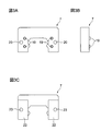
- 3A, 3B, and 3C are a front view, a side view, and a rear view of the lubricant container according to the first embodiment.
- 4A and 4B are a rear view and a side view of the lubricant container in the first embodiment.
- the dotted line in FIG. 4B has shown the internal structure of the lubricant container.
- 5A, 5B, 5C, and 5D are a side view, a front view, and a side view and a front view, respectively, of one lid of the lubricant container in the first embodiment.
- FIG. 6A and 6B are views showing a state in which the lubricant container in the first embodiment is attached to the end cap, that is, a sectional view taken along the line 6A-6A in FIG. 2A and a partially enlarged view of FIG. 6A.
- 7A and 7B are a side view of the slider main body and a diagram showing an end face of the slider main body in the first embodiment.
- FIG. 8 is a view showing a side seal in the first embodiment.
- FIG. 9A to FIG. 9C are diagrams sequentially illustrating the state of assembling the slider in the first embodiment, that is, a diagram illustrating an end surface and a side surface of the slider.
- 10A and 10B are an external view and a side view of the linear guide device of the second embodiment.
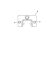
- FIG. 11A, 11B, and 11C are a front view, a side view, and a rear view of the lubricant container in the second embodiment.
- 12A and 12B are a rear view and a side view of the lubricant container in the second embodiment.
- the dotted line in FIG. 12B has shown the internal structure of the lubricant container.
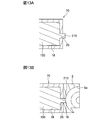
- FIG. 13A and FIG. 13B are views showing the lubricating member held in the lubricant container in the second embodiment and a view showing the state where the lubricant container is attached to the end cap, that is, corresponding to FIG. 6A of the first embodiment. It is sectional drawing.
- FIG. 14A to FIG. 14C are views sequentially showing the state of assembling the slider in the second embodiment, that is, a view showing an end face and a side face of the slider.
- a linear guide device 1 according to this embodiment shown in FIG. 1 is suitable for a numerically controlled machine tool, a numerically controlled measuring machine, and the like, and includes a guide rail 2 and a slider 3 that can move along the guide rail 2.
- the guide rail 2 is formed of a substantially square member, and two rolling grooves 2a extending in the longitudinal direction are formed on both side surfaces thereof.
- the slider 3 includes a slider body 4, an end cap 5, a lubricant container 7, and a side seal 8 that are attached to the longitudinal direction of the slider body 4, that is, the left and right ends in FIG. 1B in order from the slider body 4 side. Consists of.
- the slider body 4 is made of a metal member that extends in the longitudinal direction of the guide rail 2 and has a substantially U-shaped cross section, and is straddled over the guide rail 2.
- the portion of the slider body 4 facing the both side surfaces of the guide rail 2, that is, the inner surface of the leg portions on both sides, is a roller extending in the longitudinal direction facing the rolling groove 2a of the guide rail 2.
- Two moving grooves 4a are formed.
- the rolling groove 4a of the slider body 4 and the rolling groove 2a of the guide rail 2 form a rolling path of a rolling element (not shown).
- the rolling path is loaded with a plurality of balls as rolling elements.
- the leg portions on both sides of the slider body 4 penetrate through the slider body 4 in the longitudinal direction, that is, in the direction perpendicular to the paper surface of FIG. Has been. Further, two screw holes 11 and 12 are formed in each end face of the slider body 4.
- the end cap 5 is a resin member and has a substantially U shape as shown in FIG.
- the direction change path 5a communicates the rolling path and the return path 4b, and has a semicircular arc shape as shown in FIG. 6A.
- circular through holes 13 and 14 are formed in the end cap 5 at positions facing the screw holes 11 and 12 of the slider body 4, respectively.
- the end cap 5 is not limited to resin, but may be made of metal.
- the side seal 8 is a substantially U-shaped resin or rubber plate member as shown in FIG. 8, and has a shape straddling both side surfaces and the upper surface of the guide rail 2. With the side seal 8 having such a shape, when the slider 3 is linearly moved on the guide rail 2, foreign matters such as dust, dust and dirt adhering to both side surfaces and the upper surface of the guide rail 2 can be removed. it can.
- the side seal 8 is formed with circular through holes 9 at positions facing the screw holes 12 of the slider body 4.
- the oil supply device for a linear guide device supplies a lubricant into the slider 3 and includes an end cap 5, a lubricant container 7, and a lubricant member 15 described later.
- a circular through-hole 16 extending in the longitudinal direction of the slider 3, that is, in the left-right direction in FIG. 6A, is formed in the direction changing path 5a of the end cap 5. See also FIG. 2A.
- the lubricant container 7 is for holding the lubricating member 15 and is a resin thick plate member having substantially the same outer shape as the end cap 5 and having a substantially U-shape as shown in FIG. Yes.
- a recess that forms a substantially cubic space on the back surface of the lubricant container 7, that is, on the outer surface in the longitudinal direction of the slider 3, at a position facing the four through holes 16 of the end cap 5. 18 are provided.
- cylindrical portions 19 are integrally formed on the front surface of the lubricant container 7 at positions facing the four recesses 18 and facing the four through holes 16 of the end cap 5. Has been.
- FIG. 4A a recess that forms a substantially cubic space on the back surface of the lubricant container 7, that is, on the outer surface in the longitudinal direction of the slider 3, at a position facing the four through holes 16 of the end cap 5.
- cylindrical portions 19 are integrally formed on the front surface of the lubricant container 7 at positions facing the four recesses 18 and facing the four through holes
- the cylindrical portion 19 extends in the longitudinal direction of the slider 3, that is, in the right direction in FIG. 6A, and has a cylindrical shape that fits into the through hole 16 of the direction change path 5 a in the end cap 5. is doing.
- circular through holes 20 are respectively formed at positions facing the two screw holes 12 of the slider body 4.
- a lubricating member 15 made of a porous molded body impregnated with a lubricant is held in the recess 18 of the lubricant container 7.
- the lubricating member 15 has a substantially cubic shape that fits into the recess 18, and a columnar protrusion 21 that fits into the circular opening of the tubular portion 19 is integrally formed. That is, the lubricating member 15 is filled in the space formed by the concave portion 18 and the cylindrical portion 19 of the lubricant container 7 without a gap.
- the recess 18 holding the lubricating member 15 is sealed with a lid 22 attached from the back side of the lubricant container 7. As shown in FIG.
- the lid 22 is made of the same resin plate member as the lubricant container 7, and has a rectangular shape for sealing the two concave portions 18 of the lubricant container 7 at a time.
- a circular through hole 23 is formed in the lid 22 at a position facing the through hole 20 of the lubricant container 7.
- the length of the protruding portion 21 that forms the cylindrical portion 19 of the lubricant container 7 and the protruding portion 21 of the lubricating member 15 is the cylindrical portion 19 and the protruding portion. It is designed so that no step is generated between the portion 21 and the rolling groove of the direction changing path 5 a of the end cap 5.
- the front end surface of the cylindrical part 19 of the lubricant container 7 and the front end surface of the projection part 21 of the lubrication member 15 are curved surfaces along the rolling groove of the direction changing path 5a of the end cap 5 as shown in FIG. 6B. Each is processed.
- the lubricant container 7 is previously sealed by inserting the lubricating member 15 into each recess 18 and attaching a lid 22 from the back side.
- Procedure 1 As shown in FIG. 9A, the end caps 5 are arranged on both ends of the slider body 4 in the longitudinal direction so that the surfaces on which the direction change paths 5a are formed, that is, the front faces. Then, the screw 24 is fixed to the screw hole 11 of the slider body 4 through the through hole 13 of the end cap 5. The through hole 13 and the screw hole 11 are not shown in FIG. Thereby, the attachment of the end cap 5 to the slider body 4 is achieved.
- Procedure 2 As shown in FIG. 9B, the lubricant container 7 is attached to each end cap 5 from the outside in the longitudinal direction of the slider body 4 with the surface on which the cylindrical portion 19 is formed, that is, the front facing. The cylindrical portion 19 is not shown in FIG. At this time, the cylindrical portion 19 of the lubricant container 7 is inserted into each through hole 16 of the end cap 5. Thereby, positioning of the lubricant container 7 with respect to the end cap 5 is achieved.
- Procedure 3 As shown in FIG. 9C, side seals 8 are arranged on the lubricant containers 7 from the outside in the longitudinal direction of the slider body 4. Then, the screw 26 is passed through the through hole 9 of the side seal 8, the through hole 23 of the lid 22 of the lubricant container 7, the through hole 20 of the lubricant container 7, and the through hole 14 of the end cap 5 in order. Fix to the screw hole 12. The through holes 9 and 20 and the screw hole 12 are not shown in FIG. Thereby, attachment of the lubricant container 7 and the side seal 8 to the slider body 4 is achieved.
- the slider 3 can be easily assembled by the above assembly procedure.
- the lubricant container 7 can be positioned with respect to the end cap 5 by inserting the cylindrical portions 19 of the lubricant container 7 into the four through holes 16 of the end cap 5 as described above. it can.
- the lubricant container 7 can be easily fixed to the slider body 4 together with the side seal 8 with the common screw 26.
- the lubricating members 15 are respectively held in the four concave portions 18 of the lubricant container 7 as described above, the four lubricating members 15 can be handled by the lubricant container 7 at a time. For this reason, not only the assembly of the slider 3 becomes easy, but also the maintenance of the slider 3 becomes easy. Further, since the lubricating members 15 can be handled individually, it is possible to supply oil to the slider 3 without deviation.
- the tip of the cylindrical portion 19 of the lubricant container 7 and the tip of the protruding portion 21 of the lubricant member 15 are connected to the direction changing path 5a of the end cap 5 as shown in FIG.
- the through hole 16 is exposed inside, and a curved surface is formed in the through hole 16 along the rolling groove of the direction changing path 5a. More specifically, the distal end surface of the cylindrical portion 19 of the lubricant container 7 and the distal end surface of the protruding portion 21 of the lubricant member 15 form a single curved surface together with the rolling groove of the direction changing path 5a.
- the tip of the cylindrical portion 19 of the lubricant container 7 and the tip of the protruding portion 21 of the lubricant member 15 form a curved surface along the rolling groove of the direction changing path 5a.
- a moving body can roll smoothly in the direction change path 5a.
- the rolling element does not collide with the lubricating member 15 as in the prior art, and the lubricating member 15 is not damaged and the fragments do not enter the direction change path 5a and the rolling element as foreign matter.
- the oil supply device for a linear guide device includes an end cap 5, a lubricant container 70, and a lubricant member 150.
- the lubricating member 150 held in the concave portion 18 of the lubricant container 70 has a substantially cubic shape that fits into the concave portion 18, and is inside the longitudinal direction of the slider 30, that is, in the right direction in FIG. 13A.
- a protrusion 210 that extends to the outside from the circular opening 25 of the lubricant container 70 is integrally formed.
- the protrusion 210 has a cylindrical shape that fits into the circular opening 25 of the lubricant container 70 and the through hole 16 of the end cap 5.
- the protruding portion of the lubricating member 150 is inserted into the through hole 16 of the direction changing path 5 a of the end cap 5.
- 210 can be fitted.
- the protrusion part 210 of the lubricating member 150 can be exposed in the direction change path 5a.
- the length of the protrusion 210 of the lubricating member 150 in the longitudinal direction of the slider body 4, that is, in the left-right direction in FIG. 13B is between the protrusion 210 and the rolling groove of the direction change path 5 a of the end cap 5. It is designed so that there is no step.
- the front end surface of the projection part 210 of the lubricating member 150 is processed into the curved surface shape along the rolling groove of the direction change path 5a of the end cap 5, as shown to FIG. 13B.
- the lubricant container 70 is sealed in advance by inserting the lubricating member 150 into each recess 18 and attaching the lid 22 from the back side.
- Procedure 1 The procedure is the same as the procedure 1 of the assembling procedure of the slider 3 in the first embodiment. See FIG. 14A.
- Procedure 2 As shown in FIG. 14B, the lubricant container 70 is attached to each end cap 5 from the outside in the longitudinal direction of the slider body 4 with the surface where the circular opening 25 is formed, that is, the front facing. The circular opening 25 is not shown in FIG. At this time, the protrusions 210 of the lubricating member 150 are inserted into the respective through holes 16 of the end cap 5. Thereby, the positioning of the lubricant container 70 with respect to the end cap 5 is achieved.
- Procedure 3 The same as the procedure 3 of the assembly procedure of the slider 3 in the first embodiment. See Figure 14C.
- the slider 30 can be easily assembled by the above assembly procedure.
- the lubricant container 70 can be positioned with respect to the end cap 5 by inserting the protrusions 210 of the lubricating member 150 into the four through holes 16 of the end cap 5 as described above. For this reason, there can exist an effect similar to the said 1st Embodiment.
- the tip of the protrusion 210 of the lubricating member 150 is exposed from the through hole 16 in the direction change path 5a of the end cap 5 as shown in FIG.
- a curved surface is formed in 16 along the rolling groove of the direction change path 5a. More specifically, the tip surface of the protrusion 210 of the lubricating member 150 forms a single curved surface together with the rolling groove of the direction changing path 5a. With this configuration, the same effects as those of the first embodiment can be obtained.
- the cylindrical portion 19 has a processing accuracy due to the processing accuracy of the cylindrical portion 19.
- a rolling element can roll the inside of the direction change path 5a more smoothly. Therefore, it is possible to effectively prevent the rolling elements and the direction change path 5a from being damaged, and to effectively prevent the failure and malfunction of the slider 3.
- the through-hole 16 of the direction changing path 5a of the end cap 5 is circular.
- the cylindrical portion 19 of the lubricant container 7 has a cylindrical shape, and lubrication is performed.
- the protruding portion 21 of the member 15 has a cylindrical shape.
- the circular opening 25 is provided in the lubricant container 70, and the protrusion part 210 of the lubricating member 150 is made into the column shape.
- the present invention is not limited to this, and the through holes 16 of the direction changing path 5a may be rectangular, for example, and the respective parts of the lubricant containers 7 and 70 and the lubricating members 15 and 150 may be configured to correspond thereto.
- the lubricant containers 7 and 70 include the four lubricating members 15 and 150 corresponding to the four through holes 16 of the direction changing path 5 a of the end cap 5.
- the present invention is not limited to this.
- two lubrication members having two protrusions 21 and 210 may be prepared, and a lubricant container having two recesses for holding the two lubrication members may be configured.
- the lubricant containers 7 and 70 and the lid 22 are both made of resin, but are not limited thereto and may be made of metal.
- each of the concave portions 18 of the lubricant containers 7 and 70 holds the lubricating members 15 and 150 made of a porous molded body impregnated with the lubricant.
- the present invention is not limited to this, and a configuration may be adopted in which a lubricant such as grease or lubricating oil is held in each recess 18 of the lubricant containers 7 and 70.
- the lubricant may be filled in the space formed by the concave portion 18 and the cylindrical portion 19 of the lubricant container 7.
- a synthetic resin specifically, high chemical resistance polyethylene (PE), polypropylene (PP), polyamide (PA), or polyacetal (POM) is used as the material for the lubricant containers 7 and 70.
- PE high chemical resistance polyethylene
- PP polypropylene
- PA polyamide
- POM polyacetal
- the end cap 5 is preferably made of elastic POM as a material so that it can be easily attached to the slider body 4.
- the lubricant containers 7 and 70 can also be easily attached to the end cap 5 and can absorb minute vibrations intermittently generated when the sliders 3 and 30 pass through the joint between the guide rail 2 and the guide rail 2. It is particularly preferable to use POM as a material.
- a polymer material in particular, a polyolefin such as polypropylene or polyethylene, as the material of the lubricating members 15 and 150.
- Polyolefin has a specific gravity of 1 or less and is lightweight. Therefore, when the lubricating members 15 and 150 are made of polyolefin, the load applied from the lubricating members 15 and 150 to the lubricant containers 7 and 70 is reduced, which is effective for the lubricant containers 7 and 70.
- Polyolefin has high insulation.
- the cylindrical portion 19 of the lubricant container 7 exposed to the direction changing path 5a of the end cap 5 and the protrusion 21 of the lubricating member 15 are connected to the direction changing path 5a. It is flush with the groove. For this reason, the protrusion 21 of the lubricating member 15 is not destroyed even if the rolling elements collide. Since the POM has elasticity as described above, if the lubricating member 15 is made of POM, such an effect can be maximized and the lubricating member 15 can be well protected. This also applies to the protrusion 210 of the lubricating member 150 in the second embodiment.
- lubricating members 15 and 150 animal hair such as wool, aramid, glass, cellulose, nylon, polyester, polyether, polyolefin, rayon and the like can be used.
- the lubricating members 15 and 150 can be used as felt.
- the linear guide device oil supply device is provided at both end portions of the slider body 4, but is not limited thereto, and may be provided only at one end portion of the slider body 4.
- bowl as a rolling element is shown, it is not restricted to this, The linear guide apparatus provided with the roller as a rolling element can also be comprised.
Landscapes
- Engineering & Computer Science (AREA)
- General Engineering & Computer Science (AREA)
- Mechanical Engineering (AREA)
- Bearings For Parts Moving Linearly (AREA)
Abstract
リニアガイド装置用給油装置は、エンドキャップ5と、潤滑剤を保持しエンドキャップ5に隣接して配置された容器7とからなる。エンドキャップ5には方向転換路5aから容器7へ向かって延びた貫通孔16が形成されている。容器7にはエンドキャップ5の貫通孔16に連通する開口が形成されている。潤滑剤は、容器7の開口とエンドキャップ5の貫通孔16を経て方向転換路5a内に給油される。これにより、転動体やエンドキャップの方向転換路の損傷を防止しながらスライダに給油可能である。
Description
本発明は、リニアガイド装置用給油装置、リニアガイド装置に関する。
従来、スライダ内の転動体をスムーズに転動させるために、エンドキャップの方向転換路に配置した潤滑部材に転動体を接触させることで給油を行う構成のリニアガイド装置が知られている。例えば、特開平2009-63059号公報、特開平2009-68611号公報を参照。
しかしながら、上述のような従来のリニアガイド装置では、エンドキャップの方向転換路に配置した潤滑部材に転動体が衝突すると、潤滑部材が破損してその破片が方向転換路と転動体との間に入り込んでしまう。これにより、方向転換路の表面が塑性変形して盛り上がり、この盛り上がった箇所を転動体が通過するたびに、転動体と方向転換路は繰り返し荷重を受ける。このため、局所的に応力が発生して転動体と方向転換路に剥離やアブレシブ摩耗等の損傷が発生し、スライダの故障や動作不良を招いてしまうおそれがある。
また、上述のような従来のリニアガイド装置では、エンドキャップの方向転換路と潤滑部材との間に段差が生じる。このため、方向転換路を転動する転動体が当該段差に衝突することにより、転動体の軌道からずれ、所謂ちどり走行してしまう。これにより、転動体と方向転換路に凝着等の損傷が発生し、スライダの故障や動作不良を招いてしまうおそれがある。
そこで本発明は上記問題点に鑑みてなされたものであり、エンドキャップの方向転換路や転動体の損傷を防止しながらスライダに給油可能なリニアガイド装置用給油装置、及びこれを備えたリニアガイド装置を提供することを目的とする。
上記課題を解決するために本発明は、
スライダの長手方向の端部に配置されており、前記スライダ内の転動体の転動方向を転換するための方向転換路を有するエンドキャップと、
潤滑剤を保持し、前記エンドキャップに隣接して配置された容器とからなり、
前記エンドキャップには、前記方向転換路から前記容器へ向かって延びた貫通孔が形成されており、
前記容器には、前記エンドキャップの前記貫通孔に連通する開口が形成されており、
前記潤滑剤は、前記容器の前記開口と前記エンドキャップの前記貫通孔を経て前記方向転換路内に給油されることを特徴とするリニアガイド装置用給油装置を提供する。
スライダの長手方向の端部に配置されており、前記スライダ内の転動体の転動方向を転換するための方向転換路を有するエンドキャップと、
潤滑剤を保持し、前記エンドキャップに隣接して配置された容器とからなり、
前記エンドキャップには、前記方向転換路から前記容器へ向かって延びた貫通孔が形成されており、
前記容器には、前記エンドキャップの前記貫通孔に連通する開口が形成されており、
前記潤滑剤は、前記容器の前記開口と前記エンドキャップの前記貫通孔を経て前記方向転換路内に給油されることを特徴とするリニアガイド装置用給油装置を提供する。
また、本発明は、
前記リニアガイド装置用給油装置を備えたことを特徴とするリニアガイド装置を提供する。
前記リニアガイド装置用給油装置を備えたことを特徴とするリニアガイド装置を提供する。
本発明によれば、エンドキャップの方向転換路や転動体の損傷を防止しながらスライダに給油可能なリニアガイド装置用給油装置、及びこれを備えたリニアガイド装置を提供することができる。
(第1実施形態)
本発明の各実施形態に係るリニアガイド装置用給油装置を備えたリニアガイド装置を添付図面に基づいて説明する。
本明細書においては、リニアガイド装置の案内レールを水平にした状態において、案内レールの長手方向に対して水平方向へ直角に交差する方向を幅方向とし、長手方向及び幅方向に対して垂直に交差する方向を上下方向とする。また、案内レールの長手方向へ延在する上側の面、下側の面及び幅方向側の面をそれぞれ上面、下面及び側面とし、長手方向の端部側の面を端面とする。
本発明の各実施形態に係るリニアガイド装置用給油装置を備えたリニアガイド装置を添付図面に基づいて説明する。
本明細書においては、リニアガイド装置の案内レールを水平にした状態において、案内レールの長手方向に対して水平方向へ直角に交差する方向を幅方向とし、長手方向及び幅方向に対して垂直に交差する方向を上下方向とする。また、案内レールの長手方向へ延在する上側の面、下側の面及び幅方向側の面をそれぞれ上面、下面及び側面とし、長手方向の端部側の面を端面とする。
はじめに、本実施形態に係るリニアガイド装置用給油装置を備えたリニアガイド装置の全体的な構成について図1を参照して説明する。
図1に示す本実施形態のリニアガイド装置1は、数値制御工作機や数値制御測定機等に好適なものであり、案内レール2と、案内レール2に沿って移動可能なスライダ3とからなる。
案内レール2は、略四角型の部材からなり、その両側面には長手方向へ延びる転動溝2aが2本ずつ形成されている。
スライダ3は、スライダ本体4と、スライダ本体4の長手方向、即ち図1Bの左右方向の両端部に、スライダ本体4側から順に取り付けられたエンドキャップ5、潤滑剤容器7、及びサイドシール8とからなる。
図1に示す本実施形態のリニアガイド装置1は、数値制御工作機や数値制御測定機等に好適なものであり、案内レール2と、案内レール2に沿って移動可能なスライダ3とからなる。
案内レール2は、略四角型の部材からなり、その両側面には長手方向へ延びる転動溝2aが2本ずつ形成されている。
スライダ3は、スライダ本体4と、スライダ本体4の長手方向、即ち図1Bの左右方向の両端部に、スライダ本体4側から順に取り付けられたエンドキャップ5、潤滑剤容器7、及びサイドシール8とからなる。
スライダ本体4は、図1A及び図7に示すように、案内レール2の長手方向へ延在し断面が略コ字状をした金属製部材からなり、案内レール2に跨嵌されている。図7Bに示すように、スライダ本体4において案内レール2の両側面に対向する部分、即ち両側の脚部の内側面には、案内レール2の転動溝2aと対向して長手方向へ延びる転動溝4aが2本ずつ形成されている。
斯かるスライダ本体4の転動溝4aと案内レール2の転動溝2aとは、不図示の転動体の転動路を形成している。なお、この転動路には転動体として複数のボールが装填されている。
図7Bに示すように、スライダ本体4の両側の脚部には、スライダ本体4の長手方向、即ち図7Bの紙面垂直方向へ貫通しており、断面が円形の戻し路4bが2本ずつ形成されている。また、スライダ本体4の両端面にはネジ穴11、12が2箇所ずつ形成されている。
斯かるスライダ本体4の転動溝4aと案内レール2の転動溝2aとは、不図示の転動体の転動路を形成している。なお、この転動路には転動体として複数のボールが装填されている。
図7Bに示すように、スライダ本体4の両側の脚部には、スライダ本体4の長手方向、即ち図7Bの紙面垂直方向へ貫通しており、断面が円形の戻し路4bが2本ずつ形成されている。また、スライダ本体4の両端面にはネジ穴11、12が2箇所ずつ形成されている。
エンドキャップ5は、樹脂製の部材であって、図2に示すように略コ字状をしている。エンドキャップ5の正面、即ちスライダ本体4側の面には、図2Aに示すように、断面が円形の方向転換路5aが両側の脚部に2箇所ずつ形成されている。方向転換路5aは、上記転動路と戻し路4bとを連通するものであり、図6Aに示すように半円弧状をしている。また、エンドキャップ5には、スライダ本体4のネジ穴11、12に対向する位置に、円形の貫通穴13、14がそれぞれ形成されている。なお、エンドキャップ5は樹脂製に限らず、金属製でもよい。
上記構成により、スライダ3は複数の転動体が上記転動路内を転動することによって案内レール2上を直線運動することができる。なお、複数の転動体は転動路、方向転換路5a、及び戻し路4bを循環することが可能である。
サイドシール8は、図8に示すように略コ字状をした樹脂製又はゴム製の板部材であって、案内レール2の両側面及び上面に跨嵌する形状をしている。斯かる形状のサイドシール8により、スライダ3を案内レール2上で直線運動させた際に、案内レール2の両側面や上面に付着している塵、埃、ゴミ等の異物を除去することができる。なお、サイドシール8には、スライダ本体4のネジ穴12に対向する位置に、円形の貫通穴9がそれぞれ形成されている。
サイドシール8は、図8に示すように略コ字状をした樹脂製又はゴム製の板部材であって、案内レール2の両側面及び上面に跨嵌する形状をしている。斯かる形状のサイドシール8により、スライダ3を案内レール2上で直線運動させた際に、案内レール2の両側面や上面に付着している塵、埃、ゴミ等の異物を除去することができる。なお、サイドシール8には、スライダ本体4のネジ穴12に対向する位置に、円形の貫通穴9がそれぞれ形成されている。
次に、本実施形態において最も特徴的なリニアガイド装置用給油装置の構成について説明する。
本実施形態に係るリニアガイド装置用給油装置は、スライダ3内へ潤滑剤を給油するものであり、エンドキャップ5と、潤滑剤容器7と、後述する潤滑部材15とによって構成されている。
エンドキャップ5の方向転換路5aには、図6Aに示すように、スライダ3の長手方向、即ち図6Aの左右方向へ延びる円形の貫通孔16が形成されている。図2Aも参照。
本実施形態に係るリニアガイド装置用給油装置は、スライダ3内へ潤滑剤を給油するものであり、エンドキャップ5と、潤滑剤容器7と、後述する潤滑部材15とによって構成されている。
エンドキャップ5の方向転換路5aには、図6Aに示すように、スライダ3の長手方向、即ち図6Aの左右方向へ延びる円形の貫通孔16が形成されている。図2Aも参照。
潤滑剤容器7は、潤滑部材15を保持するためのものであり、エンドキャップ5と略同じ外形をした樹脂製の厚板部材であって、図3に示すように略コ字状をしている。図4Aに示すように、潤滑剤容器7の背面、即ちスライダ3の長手方向外側の面には、エンドキャップ5の4つの貫通孔16に対向する位置に、略立方体形状の空間を形成する凹部18がそれぞれ設けられている。
潤滑剤容器7の正面には、図3Aに示すように、4つの凹部18に対向し、かつエンドキャップ5の4つの貫通孔16に対向する位置に、筒状部19がそれぞれ一体的に形成されている。筒状部19は、図6Aに示すように、スライダ3の長手方向内側、即ち図6Aの右方向へ延びており、エンドキャップ5における方向転換路5aの貫通孔16に嵌合する円筒形状をしている。筒状部19内の円形開口である中空部は、対向する凹部18の底面を貫通している。
なお、潤滑剤容器7には、スライダ本体4の2つのネジ穴12に対向する位置に、円形の貫通穴20がそれぞれ形成されている。
潤滑剤容器7の正面には、図3Aに示すように、4つの凹部18に対向し、かつエンドキャップ5の4つの貫通孔16に対向する位置に、筒状部19がそれぞれ一体的に形成されている。筒状部19は、図6Aに示すように、スライダ3の長手方向内側、即ち図6Aの右方向へ延びており、エンドキャップ5における方向転換路5aの貫通孔16に嵌合する円筒形状をしている。筒状部19内の円形開口である中空部は、対向する凹部18の底面を貫通している。
なお、潤滑剤容器7には、スライダ本体4の2つのネジ穴12に対向する位置に、円形の貫通穴20がそれぞれ形成されている。
潤滑剤容器7の凹部18には、図6Aに示すように、潤滑剤を含浸した多孔質成形体からなる潤滑部材15が保持されている。潤滑部材15は、凹部18に嵌合する略立方体形状をしており、筒状部19の円形開口に嵌合する円柱状の突起部21が一体的に形成されている。即ち、潤滑部材15は、潤滑剤容器7の凹部18と筒状部19とによって形成される空間内に隙間なく充填されている。
潤滑部材15を保持した凹部18は、図3Cに示すように、潤滑剤容器7の背面側より蓋22が取り付けられて密封される。蓋22は、図5に示すように、潤滑剤容器7と同じ樹脂製の板部材からなり、潤滑剤容器7の2つの凹部18を一度に密封するために長方形状をしている。なお、蓋22には、潤滑剤容器7の貫通穴20に対向する位置に円形の貫通穴23が形成されている。
潤滑部材15を保持した凹部18は、図3Cに示すように、潤滑剤容器7の背面側より蓋22が取り付けられて密封される。蓋22は、図5に示すように、潤滑剤容器7と同じ樹脂製の板部材からなり、潤滑剤容器7の2つの凹部18を一度に密封するために長方形状をしている。なお、蓋22には、潤滑剤容器7の貫通穴20に対向する位置に円形の貫通穴23が形成されている。
上記構成により、図6Aに示すように、潤滑部材15を保持した潤滑剤容器7をエンドキャップ5に取り付けた際に、エンドキャップ5の方向転換路5aの貫通孔16に潤滑剤容器7の筒状部19を嵌合させることができる。そして、潤滑剤容器7の筒状部19と該筒状部19の円形開口に嵌合した潤滑部材15の突起部21とを方向転換路5a内へ露呈させることができる。
ここで、スライダ本体4の長手方向、即ち図6の左右方向における潤滑剤容器7の筒状部19と潤滑部材15の突起部21となる凸部21の長さは、筒状部19及び突起部21とエンドキャップ5の方向転換路5aの転動溝との間に段差が生じないようにそれぞれ設計されている。そして、潤滑剤容器7の筒状部19の先端面及び潤滑部材15の突起部21の先端面は、図6Bに示すようにエンドキャップ5の方向転換路5aの転動溝に沿った曲面形状にそれぞれ加工されている。
ここで、スライダ本体4の長手方向、即ち図6の左右方向における潤滑剤容器7の筒状部19と潤滑部材15の突起部21となる凸部21の長さは、筒状部19及び突起部21とエンドキャップ5の方向転換路5aの転動溝との間に段差が生じないようにそれぞれ設計されている。そして、潤滑剤容器7の筒状部19の先端面及び潤滑部材15の突起部21の先端面は、図6Bに示すようにエンドキャップ5の方向転換路5aの転動溝に沿った曲面形状にそれぞれ加工されている。
以下、本実施形態におけるスライダ3の組み立て手順について図9を参照して説明する。
なお、予め潤滑剤容器7は、各凹部18に潤滑部材15を挿入し、背面側より蓋22を取り付けて密封しておく。
なお、予め潤滑剤容器7は、各凹部18に潤滑部材15を挿入し、背面側より蓋22を取り付けて密封しておく。
手順1:図9Aに示すように、スライダ本体4の長手方向の両端部に、エンドキャップ5を方向転換路5aが形成された面、即ち正面を向けて配置する。そして、ネジ24をエンドキャップ5の貫通穴13を通してスライダ本体4のネジ穴11に固定する。貫通穴13及びネジ穴11は図9において不図示である。これにより、スライダ本体4に対するエンドキャップ5の取り付けが達成される。
手順2:図9Bに示すように、各エンドキャップ5に対して、スライダ本体4の長手方向外側から、潤滑剤容器7を筒状部19が形成された面、即ち正面を向けて取り付ける。筒状部19は図9において不図示である。このとき、エンドキャップ5の各貫通孔16に潤滑剤容器7の筒状部19をそれぞれ挿入させる。これにより、エンドキャップ5に対して潤滑剤容器7の位置決めが達成される。
手順3:図9Cに示すように、各潤滑剤容器7に対して、スライダ本体4の長手方向外側からサイドシール8を配置する。そして、ネジ26をサイドシール8の貫通穴9、潤滑剤容器7の蓋22の貫通穴23、潤滑剤容器7の貫通穴20、及びエンドキャップ5の貫通穴14を順に通してスライダ本体4のネジ穴12に固定する。貫通穴9、20及びネジ穴12は図7において不図示である。これにより、スライダ本体4に対する潤滑剤容器7及びサイドシール8の取り付けが達成される。
以上の組み立て手順により、スライダ3を容易に組み立てることができる。特に、手順2において、上述のようにエンドキャップ5の4つの貫通孔16に潤滑剤容器7の筒状部19をそれぞれ挿入することで、エンドキャップ5に対する潤滑剤容器7の位置決めを行うことができる。このため、手順3において、スライダ本体4に対して潤滑剤容器7をサイドシール8とともに共通のネジ26で容易に固定することができる。また、上述のように潤滑剤容器7の4つの凹部18に潤滑部材15がそれぞれ保持される構成であるため、潤滑剤容器7によって4つの潤滑部材15を一度に取り扱うことができる。このため、スライダ3の組み立てが容易になるだけでなく、スライダ3のメンテナンスも容易となる。また、潤滑部材15を個々に扱うことができるため、スライダ3へ偏りなく給油することができる。
以上の組み立て手順に基づいて組み立てたスライダ3において、潤滑剤容器7の筒状部19の先端及び潤滑部材15の突起部21の先端は、図6に示すようにエンドキャップ5の方向転換路5a内に貫通孔16から露呈し、この貫通孔16内に方向転換路5aの転動溝に沿って曲面を形成している。より詳細には、潤滑剤容器7の筒状部19の先端面及び潤滑部材15の突起部21の先端面は、方向転換路5aの転動溝とともに単一の曲面を形成している。
この構成により、スライダ3を案内レール2上で直線運動させた際に、方向転換路5aを転動する転動体が潤滑部材15の突起部21の先端面に接触して潤滑剤を塗布されることにより、スライダ3内へ給油することができる。
この構成により、スライダ3を案内レール2上で直線運動させた際に、方向転換路5aを転動する転動体が潤滑部材15の突起部21の先端面に接触して潤滑剤を塗布されることにより、スライダ3内へ給油することができる。
また、前述のように潤滑剤容器7の筒状部19の先端及び潤滑部材15の突起部21の先端が、方向転換路5aの転動溝に沿って曲面を形成していることにより、転動体が方向転換路5a内をスムーズに転動することができる。このため、上記従来技術のように転動体が潤滑部材15に衝突し、潤滑部材15が破損してその破片が方向転換路5aと転動体との間に異物として入り込んでしまうようなことがない。また、上記従来技術のように方向転換路5aと潤滑部材15との間に段差が生じ、この段差に転動体が衝突してちどり走行するおそれもない。したがって、転動体と方向転換路5aの損傷を防ぎ、スライダ3の故障や動作不良を防止することができる。
(第2実施形態)
図10に示す第2実施形態に係るリニアガイド装置用給油装置を備えたリニアガイド装置100について、上記第1実施形態と同様の構成については同じ符号を付して説明を省略し、異なる構成について詳細に説明する。
本実施形態に係るリニアガイド装置用給油装置は、エンドキャップ5と、潤滑剤容器70と、潤滑部材150とによって構成されている。
図10に示す第2実施形態に係るリニアガイド装置用給油装置を備えたリニアガイド装置100について、上記第1実施形態と同様の構成については同じ符号を付して説明を省略し、異なる構成について詳細に説明する。
本実施形態に係るリニアガイド装置用給油装置は、エンドキャップ5と、潤滑剤容器70と、潤滑部材150とによって構成されている。
本実施形態における潤滑剤容器70には、上記第1実施形態における潤滑剤容器7の筒状部19に代えて、図11A及び図12Aに示すように、4つの凹部18に対向し、かつエンドキャップ5の4つの貫通孔16に対向する位置に、該貫通孔16と同径の円形開口25がそれぞれ形成されている。
図13Aに示すように、潤滑剤容器70の凹部18に保持される潤滑部材150は、凹部18に嵌合する略立方体形状をしており、スライダ30の長手方向内側、即ち図13Aの右方向へ延在し潤滑剤容器70の円形開口25から外部へ突き出る突起部210が一体的に形成されている。突起部210は、図13Bに示すように、潤滑剤容器70の円形開口25及びエンドキャップ5の貫通孔16に嵌合する円柱形状をしている。
図13Aに示すように、潤滑剤容器70の凹部18に保持される潤滑部材150は、凹部18に嵌合する略立方体形状をしており、スライダ30の長手方向内側、即ち図13Aの右方向へ延在し潤滑剤容器70の円形開口25から外部へ突き出る突起部210が一体的に形成されている。突起部210は、図13Bに示すように、潤滑剤容器70の円形開口25及びエンドキャップ5の貫通孔16に嵌合する円柱形状をしている。
上記構成により、潤滑部材150を保持した潤滑剤容器70をエンドキャップ5に取り付けた際に、図13Bに示すように、エンドキャップ5の方向転換路5aの貫通孔16に潤滑部材150の突起部210を嵌合させることができる。そして、潤滑部材150の突起部210を方向転換路5a内へ露呈させることができる。
ここで、スライダ本体4の長手方向、即ち図13Bの左右方向における潤滑部材150の突起部210の長さは、該突起部210とエンドキャップ5の方向転換路5aの転動溝との間に段差が生じないように設計されている。そして、潤滑部材150の突起部210の先端面は、図13Bに示すようにエンドキャップ5の方向転換路5aの転動溝に沿った曲面形状に加工されている。
ここで、スライダ本体4の長手方向、即ち図13Bの左右方向における潤滑部材150の突起部210の長さは、該突起部210とエンドキャップ5の方向転換路5aの転動溝との間に段差が生じないように設計されている。そして、潤滑部材150の突起部210の先端面は、図13Bに示すようにエンドキャップ5の方向転換路5aの転動溝に沿った曲面形状に加工されている。
以下、本実施形態におけるスライダ30の組み立て手順について図14を参照して説明する。
なお、予め潤滑剤容器70は、各凹部18に潤滑部材150を挿入し、背面側より蓋22を取り付けて密封しておく。
手順1:上記第1実施形態におけるスライダ3の組み立て手順の手順1と同様である。図14Aを参照。
なお、予め潤滑剤容器70は、各凹部18に潤滑部材150を挿入し、背面側より蓋22を取り付けて密封しておく。
手順1:上記第1実施形態におけるスライダ3の組み立て手順の手順1と同様である。図14Aを参照。
手順2:図14Bに示すように、各エンドキャップ5に対して、スライダ本体4の長手方向外側から、潤滑剤容器70を円形開口25が形成された面、即ち正面を向けて取り付ける。円形開口25は図12において不図示である。このとき、エンドキャップ5の各貫通孔16に潤滑部材150の突起部210をそれぞれ挿入させる。これにより、エンドキャップ5に対して潤滑剤容器70の位置決めが達成される。
手順3:上記第1実施形態におけるスライダ3の組み立て手順の手順3と同様である。図14Cを参照。
手順3:上記第1実施形態におけるスライダ3の組み立て手順の手順3と同様である。図14Cを参照。
以上の組み立て手順により、スライダ30を容易に組み立てることができる。特に、手順2において、前述のようにエンドキャップ5の4つの貫通孔16に潤滑部材150の突起部210をそれぞれ挿入することで、エンドキャップ5に対する潤滑剤容器70の位置決めを行うことができる。このため、上記第1実施形態と同様の効果を奏することができる。
以上の組み立て手順に基づいて組み立てたスライダ30において、潤滑部材150の突起部210の先端が、図13Bに示すようにエンドキャップ5の方向転換路5a内に貫通孔16から露呈し、この貫通孔16内に方向転換路5aの転動溝に沿って曲面を形成している。より詳細には、潤滑部材150の突起部210の先端面は、方向転換路5aの転動溝とともに単一の曲面を形成している。この構成により、上記第1実施形態と同様の効果を奏することができる。
特に、本実施形態における潤滑剤容器70は、上記第1実施形態における潤滑剤容器7の筒状部19を有していないため、筒状部19の加工精度に起因して筒状部19の先端と方向転換路5aとの間に僅かなガタも生じるおそれがない。これにより、転動体が方向転換路5a内をよりスムーズに転動することができる。したがって、転動体と方向転換路5aの損傷を効果的に防ぎ、スライダ3の故障や動作不良を効果的に防止することができる。
上記各実施形態では、エンドキャップ5の方向転換路5aの貫通孔16は円形であり、これに対応するように、第1実施形態では潤滑剤容器7の筒状部19を円筒形状とし、潤滑部材15の突起部21を円柱形状としている。また、第2実施形態では潤滑剤容器70に円形開口25を設け、潤滑部材150の突起部210を円柱形状としている。しかしこれに限られず、方向転換路5aの貫通孔16を例えば矩形とし、これに対応するように潤滑剤容器7、70及び潤滑部材15、150の各部を構成してもよい。
また、上記各実施形態において潤滑剤容器7、70は、エンドキャップ5の方向転換路5aの4つの貫通孔16に対応して4つの潤滑部材15、150を備えている。しかしながらこれに限られず、例えば突起部21、210を2つ備えた潤滑部材を2つ用意し、この2つの潤滑部材を保持する2つの凹部を備えた潤滑剤容器を構成してもよい。
なお、潤滑剤容器7、70及び蓋22はともに樹脂製であるが、これに限られず金属製としてもよい。
なお、潤滑剤容器7、70及び蓋22はともに樹脂製であるが、これに限られず金属製としてもよい。
また、上記各実施形態では、潤滑剤容器7、70の各凹部18に、潤滑剤を含浸した多孔質成形体からなる潤滑部材15、150を保持する構成である。しかしながらこれに限られず、潤滑剤容器7、70の各凹部18に、グリースや潤滑油等の潤滑剤そのものを保持する構成としてもよい。具体的には、第1実施形態では、潤滑剤容器7の凹部18と筒状部19とによって形成される空間内に潤滑剤を充填する構成としてもよい。また、第2実施形態では、潤滑剤容器70の凹部18、円形開口25、及びエンドキャップ5における方向転換路5aの貫通孔16によって形成される空間内に潤滑剤を充填する構成としてもよい。
また、上記各実施形態では、潤滑剤容器7、70の材料として合成樹脂、具体的には耐薬品性の高いポリエチレン(PE)、ポリプロピレン(PP)、ポリアミド(PA)、ポリアセタール(POM)を用いることが好ましい。なお、エンドキャップ5は、スライダ本体4へ取り付けやすいように弾性のあるPOMを材料として用いることが好ましい。このため、潤滑剤容器7、70も、エンドキャップ5へ取り付けやすく、かつスライダ3、30が案内レール2と案内レール2との継ぎ目を通過する際に断続的に発生する微小振動を吸収できるようにPOMを材料として用いることが特に好ましい。
また、上記各実施形態では、潤滑部材15、150の材料として高分子材料、特にポリプロピレンやポリエチレン等のポリオレフィンを用いることが好ましい。
ポリオレフィンは比重が1以下で軽量である。したがって、潤滑部材15、150をポリオレフィンで構成することにより、潤滑部材15、150から潤滑剤容器7、70へかかる負荷が小さくなるため、潤滑剤容器7、70に対して有効である。
また、ポリオレフィンは絶縁性が高い。したがって、スライダ3、30が案内レール2上を走行した時にエンドキャップ5の方向転換路5aと転動体との摩擦により静電気が生じた場合でも、ポリオレフィンで構成した潤滑部材15、150で絶縁することができる。このため、静電気によって潤滑剤容器7、70が破損してしまうことを防止することができる。
ポリオレフィンは比重が1以下で軽量である。したがって、潤滑部材15、150をポリオレフィンで構成することにより、潤滑部材15、150から潤滑剤容器7、70へかかる負荷が小さくなるため、潤滑剤容器7、70に対して有効である。
また、ポリオレフィンは絶縁性が高い。したがって、スライダ3、30が案内レール2上を走行した時にエンドキャップ5の方向転換路5aと転動体との摩擦により静電気が生じた場合でも、ポリオレフィンで構成した潤滑部材15、150で絶縁することができる。このため、静電気によって潤滑剤容器7、70が破損してしまうことを防止することができる。
図6Bに示したように上記第1実施形態では、エンドキャップ5の方向転換路5aに露呈した潤滑剤容器7の筒状部19と潤滑部材15の突起部21は、方向転換路5aの転動溝と面一になっている。このため、潤滑部材15の突起部21は転動体が衝突しても破壊されることはない。POMは前述のように弾性があるため、潤滑部材15をPOMで構成すれば斯かる効果を最大限に発揮し、潤滑部材15を良好に保護することができる。なお、このことは上記第2実施形態における潤滑部材150の突起部210においても同様である。
また、図6Bに示したように潤滑剤容器7の筒状部19と潤滑部材15の突起部21とを嵌合させる構成の場合、軟質であるPEを潤滑部材15の材料に用いることで、筒状部19に突起部21を嵌めやすくなるので好ましい。なお、PEに剛性をもたせるために、PEにPPをコンパウンドすることがより好ましい。
また、図6Bに示したように潤滑剤容器7の筒状部19と潤滑部材15の突起部21とを嵌合させる構成の場合、軟質であるPEを潤滑部材15の材料に用いることで、筒状部19に突起部21を嵌めやすくなるので好ましい。なお、PEに剛性をもたせるために、PEにPPをコンパウンドすることがより好ましい。
また、潤滑部材15、150のその他の材料として羊毛等の動物の毛、アラミド、ガラス、セルロース、ナイロン、ポリエステル、ポリエーテル、ポリオレフィン、レーヨン等を用いることもできる。なお、潤滑部材15、150はフェルトにして使用することも可能である。
また、リニアガイド装置用給油装置は、スライダ本体4の両端部に備えられているが、これに限られずスライダ本体4の一方の端部のみに備える構成としてもよい。
また、上記各実施形態では、転動体としてボールを備えたリニアガイド装置1、100を示しているが、これに限られず、転動体としてころを備えたリニアガイド装置を構成することもできる。
また、上記各実施形態では、転動体としてボールを備えたリニアガイド装置1、100を示しているが、これに限られず、転動体としてころを備えたリニアガイド装置を構成することもできる。
Claims (9)
- スライダの長手方向の端部に配置されており、前記スライダ内の転動体の転動方向を転換するための方向転換路を有するエンドキャップと、
潤滑剤を保持し、前記エンドキャップに隣接して配置された容器とからなり、
前記エンドキャップには、前記方向転換路から前記容器へ向かって延びた貫通孔が形成されており、
前記容器には、前記エンドキャップの前記貫通孔に連通する開口が形成されており、
前記潤滑剤は、前記容器の前記開口と前記エンドキャップの前記貫通孔を経て前記方向転換路内に給油されることを特徴とするリニアガイド装置用給油装置。 - 前記容器は、前記潤滑剤を含浸した多孔質成形体からなる突起部を有する潤滑部材を保持し、
前記潤滑部材の前記突起部は、前記容器の前記開口から突出し、前記エンドキャップの前記貫通孔に挿入されて前記方向転換路内に露呈しており、
前記潤滑部材の前記突起部の先端は、前記方向転換路の転動溝に沿って曲面を形成していることを特徴とする請求項1に記載のリニアガイド装置用給油装置。 - 前記容器は、前記開口の位置に筒状部を有し、
前記容器の前記開口から突出した前記潤滑部材の前記突起部が、前記筒状部内の中空部に嵌合し、
前記容器の前記筒状部が前記エンドキャップの前記貫通孔に嵌合し、前記潤滑部材の前記突起部及び前記容器の前記筒状部が前記エンドキャップの前記方向転換路内に露呈しており、
前記潤滑部材の前記突起部の先端及び前記容器の前記筒状部の先端が、前記エンドキャップの前記方向転換路の転動溝に沿って曲面を形成していることを特徴とする請求項2に記載のリニアガイド装置用給油装置。 - 前記容器の前記開口から突出した前記潤滑部材の前記突起部は、前記エンドキャップの前記貫通孔に嵌合していることを特徴とする請求項2に記載のリニアガイド装置用給油装置。
- 前記容器は、前記潤滑剤を保持する凹部と、前記凹部を閉塞する蓋部材とを有し、
前記凹部の底面に前記開口が形成されていることを特徴とする請求項1に記載のリニアガイド装置用給油装置。 - 前記容器は、前記潤滑部材を保持する凹部と、前記凹部を閉塞する蓋部材とを有し、
前記凹部の底面に前記開口が形成されていることを特徴とする請求項2から請求項4のいずれか一項に記載のリニアガイド装置用給油装置。 - 前記エンドキャップは、前記方向転換路を複数有し、
複数の前記方向転換路には、それぞれに前記貫通孔が形成されており、
前記容器は、前記凹部を、前記エンドキャップの前記貫通孔と同数備えていることを特徴とする請求項5又は請求項6に記載のリニアガイド装置用給油装置。 - 請求項1から請求項7のいずれか一項に記載のリニアガイド装置用給油装置を備えたことを特徴とするリニアガイド装置。
- 前記スライダは、前記容器に隣接して配置されたサイドシールを有し、
前記サイドシール、前記容器及び前記エンドキャップには、スライダ本体の長手方向の端部に形成されたネジ穴に対向する貫通穴がそれぞれ形成されており、
ネジが前記サイドシール、前記容器及び前記エンドキャップの前記貫通穴を順に通って前記スライダ本体の前記ネジ穴に取り付けられていることを特徴とする請求項8に記載のリニアガイド装置。
Priority Applications (3)
| Application Number | Priority Date | Filing Date | Title |
|---|---|---|---|
| US14/780,547 US10294993B2 (en) | 2013-03-27 | 2014-02-28 | Lubricant supply device for linear guide apparatus, and linear guide apparatus |
| EP14776389.0A EP2980428A4 (en) | 2013-03-27 | 2014-02-28 | OIL SUPPLY DEVICE FOR LINEAR GUIDING DEVICE, AND LINEAR GUIDING DEVICE |
| CN201480000840.6A CN104246250A (zh) | 2013-03-27 | 2014-02-28 | 直线导轨装置用供油装置以及直线导轨装置 |
Applications Claiming Priority (4)
| Application Number | Priority Date | Filing Date | Title |
|---|---|---|---|
| JP2013066529 | 2013-03-27 | ||
| JP2013-066529 | 2013-03-27 | ||
| JP2014-023927 | 2014-02-11 | ||
| JP2014023927 | 2014-02-11 |
Publications (1)
| Publication Number | Publication Date |
|---|---|
| WO2014156473A1 true WO2014156473A1 (ja) | 2014-10-02 |
Family
ID=51623467
Family Applications (1)
| Application Number | Title | Priority Date | Filing Date |
|---|---|---|---|
| PCT/JP2014/055112 WO2014156473A1 (ja) | 2013-03-27 | 2014-02-28 | リニアガイド装置用給油装置、リニアガイド装置 |
Country Status (5)
| Country | Link |
|---|---|
| US (1) | US10294993B2 (ja) |
| EP (1) | EP2980428A4 (ja) |
| CN (1) | CN104246250A (ja) |
| TW (1) | TW201447129A (ja) |
| WO (1) | WO2014156473A1 (ja) |
Families Citing this family (5)
| Publication number | Priority date | Publication date | Assignee | Title |
|---|---|---|---|---|
| JP6390616B2 (ja) * | 2013-07-04 | 2018-09-19 | 日本精工株式会社 | リニアガイド装置用給油装置、リニアガイド装置 |
| CN107110207B (zh) * | 2015-02-25 | 2019-07-02 | 日本精工株式会社 | 滚动轴承导向装置用供油装置和滚动轴承导向装置 |
| DE202015102452U1 (de) * | 2015-05-13 | 2016-08-17 | Robert Bosch Gmbh | Führungswagen mit Schmierrinne und Kunststofffolie |
| JP6668652B2 (ja) | 2015-09-18 | 2020-03-18 | 日本精工株式会社 | 直動案内装置、直動案内装置用エンドキャップ |
| CN107477346B (zh) * | 2017-09-30 | 2020-11-03 | 京东方科技集团股份有限公司 | 导轨注油工具 |
Citations (5)
| Publication number | Priority date | Publication date | Assignee | Title |
|---|---|---|---|---|
| JPH0571443U (ja) * | 1992-03-02 | 1993-09-28 | 光洋精工株式会社 | 直動形ガイド装置 |
| JPH1122726A (ja) * | 1997-07-01 | 1999-01-26 | Thk Kk | 直線案内装置 |
| JP2009063059A (ja) | 2007-09-05 | 2009-03-26 | Nippon Thompson Co Ltd | 直動転がり案内ユニット用のスライダ |
| JP2009068611A (ja) | 2007-09-13 | 2009-04-02 | Nippon Thompson Co Ltd | 直動転がり案内ユニット用のスライダ |
| JP2011052700A (ja) * | 2009-08-31 | 2011-03-17 | Thk Co Ltd | 潤滑油供給装置及びこれを用いた運動案内装置 |
Family Cites Families (18)
| Publication number | Priority date | Publication date | Assignee | Title |
|---|---|---|---|---|
| JP2543304Y2 (ja) * | 1990-05-18 | 1997-08-06 | 日本精工株式会社 | リニアガイド装置の漏油防止構造 |
| JP2696446B2 (ja) * | 1991-09-10 | 1998-01-14 | 株式会社ユニシアジェックス | 筒内直接噴射型噴射弁のアシストエア供給装置 |
| DE4331013C2 (de) * | 1993-08-12 | 1998-04-09 | Schaeffler Waelzlager Ohg | Abstreifereinheit für ein Lagerelement |
| US6125968A (en) * | 1996-12-09 | 2000-10-03 | Thk Co., Ltd. | Lubricating oil supply system for a rolling guide apparatus |
| JP3935247B2 (ja) * | 1997-09-18 | 2007-06-20 | 日本トムソン株式会社 | 直動案内ユニット |
| US6401867B1 (en) * | 1998-04-16 | 2002-06-11 | Thk Co., Ltd. | Lubricant supply system |
| EP0982509B1 (de) * | 1998-08-27 | 2004-10-20 | Schneeberger Holding AG | Linearbewegungsführung |
| JP4035241B2 (ja) * | 1998-11-13 | 2008-01-16 | 日本トムソン株式会社 | 潤滑装置を備えた直動案内ユニット |
| JP4568453B2 (ja) * | 2000-05-29 | 2010-10-27 | Thk株式会社 | 運動案内装置 |
| US7473033B2 (en) * | 2006-04-07 | 2009-01-06 | Hiwin Technology Corp. | Ball circulation system for linear guide way |
| JP4965362B2 (ja) * | 2007-07-09 | 2012-07-04 | 日本トムソン株式会社 | ローラ形式の直動案内ユニット |
| JP5164699B2 (ja) | 2008-07-04 | 2013-03-21 | 日本トムソン株式会社 | 直動転がり案内ユニット用の潤滑部材および直動転がり案内ユニット用のスライダ |
| JP2012052609A (ja) * | 2010-09-01 | 2012-03-15 | Nsk Ltd | 直動案内装置 |
| EP2642143A4 (en) * | 2010-11-18 | 2016-03-02 | Nsk Ltd | DIRECT-ACTING GUIDE BEARING APPARATUS AND JOINT ELEMENT USED THEREIN |
| JP5726922B2 (ja) * | 2013-01-18 | 2015-06-03 | Thk株式会社 | 運動案内装置 |
| JP2015090187A (ja) * | 2013-11-06 | 2015-05-11 | 日本精工株式会社 | 転がり軸受案内装置 |
| DE102014210171A1 (de) * | 2014-05-28 | 2015-12-17 | Robert Bosch Gmbh | Führungswagen mit Befestigungsbohrung, welche Bestandteil eines Schmiermittelströmungspfades ist |
| EP3279487B1 (en) * | 2015-03-31 | 2020-04-22 | NSK Ltd. | Oil supply device and rectilinear motion guide device |
-
2014
- 2014-02-28 EP EP14776389.0A patent/EP2980428A4/en not_active Withdrawn
- 2014-02-28 US US14/780,547 patent/US10294993B2/en active Active
- 2014-02-28 CN CN201480000840.6A patent/CN104246250A/zh active Pending
- 2014-02-28 WO PCT/JP2014/055112 patent/WO2014156473A1/ja active Application Filing
- 2014-03-26 TW TW103111217A patent/TW201447129A/zh unknown
Patent Citations (5)
| Publication number | Priority date | Publication date | Assignee | Title |
|---|---|---|---|---|
| JPH0571443U (ja) * | 1992-03-02 | 1993-09-28 | 光洋精工株式会社 | 直動形ガイド装置 |
| JPH1122726A (ja) * | 1997-07-01 | 1999-01-26 | Thk Kk | 直線案内装置 |
| JP2009063059A (ja) | 2007-09-05 | 2009-03-26 | Nippon Thompson Co Ltd | 直動転がり案内ユニット用のスライダ |
| JP2009068611A (ja) | 2007-09-13 | 2009-04-02 | Nippon Thompson Co Ltd | 直動転がり案内ユニット用のスライダ |
| JP2011052700A (ja) * | 2009-08-31 | 2011-03-17 | Thk Co Ltd | 潤滑油供給装置及びこれを用いた運動案内装置 |
Non-Patent Citations (1)
| Title |
|---|
| See also references of EP2980428A4 |
Also Published As
| Publication number | Publication date |
|---|---|
| EP2980428A4 (en) | 2016-11-02 |
| TW201447129A (zh) | 2014-12-16 |
| CN104246250A (zh) | 2014-12-24 |
| EP2980428A1 (en) | 2016-02-03 |
| US20160061261A1 (en) | 2016-03-03 |
| US10294993B2 (en) | 2019-05-21 |
Similar Documents
| Publication | Publication Date | Title |
|---|---|---|
| WO2014156473A1 (ja) | リニアガイド装置用給油装置、リニアガイド装置 | |
| JP3636481B2 (ja) | リニアガイドのシール装置 | |
| JP6809059B2 (ja) | リニアガイド | |
| JP6445788B2 (ja) | 直動転がり案内ユニット | |
| JP6390616B2 (ja) | リニアガイド装置用給油装置、リニアガイド装置 | |
| JP6193021B2 (ja) | 直動案内ユニット | |
| JP4504663B2 (ja) | 案内装置 | |
| JP6393496B2 (ja) | 潤滑部材を備えた直動案内ユニット | |
| JP5783322B2 (ja) | 直動案内装置 | |
| US9803688B2 (en) | Rolling bearing guide apparatus | |
| JP6384083B2 (ja) | リニアガイド装置用給油装置、リニアガイド装置 | |
| JP2006317006A (ja) | 直動案内軸受装置用防塵構造 | |
| JP2008240800A (ja) | リニアガイド装置 | |
| KR20220031673A (ko) | 운동 안내 장치 및 운동 안내 장치에서 사용되는 윤활 경로 구성요소 | |
| JPH0658234U (ja) | 直動案内ユニット | |
| JP2015031378A (ja) | リニアガイド装置用給油装置 | |
| WO2015083692A1 (ja) | 転がり軸受案内装置 | |
| JP4488715B2 (ja) | 転がり案内ユニット | |
| JP2022157874A (ja) | リニアガイド装置の案内レール取付穴用キャップ及びリニアガイド装置 | |
| JP6222243B2 (ja) | 直動案内装置 | |
| JP6574585B2 (ja) | 直動案内ユニット | |
| EP2759725B1 (en) | Linear motion guide device | |
| JP2012225419A (ja) | リニアガイド装置用潤滑剤供給体、リニアガイド装置 | |
| JP2008164161A (ja) | エンドキャップ及びそれを備えた直動案内装置 | |
| JP2006170418A (ja) | 直動案内軸受装置 |
Legal Events
| Date | Code | Title | Description |
|---|---|---|---|
| 121 | Ep: the epo has been informed by wipo that ep was designated in this application |
Ref document number: 14776389 Country of ref document: EP Kind code of ref document: A1 |
|
| WWE | Wipo information: entry into national phase |
Ref document number: 2014776389 Country of ref document: EP |
|
| WWE | Wipo information: entry into national phase |
Ref document number: 14780547 Country of ref document: US |
|
| NENP | Non-entry into the national phase |
Ref country code: DE |