WO2015001930A1 - 電動車両用バッテリ交換システム及びプログラム - Google Patents
電動車両用バッテリ交換システム及びプログラム Download PDFInfo
- Publication number
- WO2015001930A1 WO2015001930A1 PCT/JP2014/065458 JP2014065458W WO2015001930A1 WO 2015001930 A1 WO2015001930 A1 WO 2015001930A1 JP 2014065458 W JP2014065458 W JP 2014065458W WO 2015001930 A1 WO2015001930 A1 WO 2015001930A1
- Authority
- WO
- WIPO (PCT)
- Prior art keywords
- battery
- station
- electric vehicle
- charging
- management server
- Prior art date
- Legal status (The legal status is an assumption and is not a legal conclusion. Google has not performed a legal analysis and makes no representation as to the accuracy of the status listed.)
- Ceased
Links
Images


Classifications
-
- B—PERFORMING OPERATIONS; TRANSPORTING
- B60—VEHICLES IN GENERAL
- B60L—PROPULSION OF ELECTRICALLY-PROPELLED VEHICLES; SUPPLYING ELECTRIC POWER FOR AUXILIARY EQUIPMENT OF ELECTRICALLY-PROPELLED VEHICLES; ELECTRODYNAMIC BRAKE SYSTEMS FOR VEHICLES IN GENERAL; MAGNETIC SUSPENSION OR LEVITATION FOR VEHICLES; MONITORING OPERATING VARIABLES OF ELECTRICALLY-PROPELLED VEHICLES; ELECTRIC SAFETY DEVICES FOR ELECTRICALLY-PROPELLED VEHICLES
- B60L53/00—Methods of charging batteries, specially adapted for electric vehicles; Charging stations or on-board charging equipment therefor; Exchange of energy storage elements in electric vehicles
- B60L53/60—Monitoring or controlling charging stations
- B60L53/66—Data transfer between charging stations and vehicles
-
- B—PERFORMING OPERATIONS; TRANSPORTING
- B60—VEHICLES IN GENERAL
- B60L—PROPULSION OF ELECTRICALLY-PROPELLED VEHICLES; SUPPLYING ELECTRIC POWER FOR AUXILIARY EQUIPMENT OF ELECTRICALLY-PROPELLED VEHICLES; ELECTRODYNAMIC BRAKE SYSTEMS FOR VEHICLES IN GENERAL; MAGNETIC SUSPENSION OR LEVITATION FOR VEHICLES; MONITORING OPERATING VARIABLES OF ELECTRICALLY-PROPELLED VEHICLES; ELECTRIC SAFETY DEVICES FOR ELECTRICALLY-PROPELLED VEHICLES
- B60L53/00—Methods of charging batteries, specially adapted for electric vehicles; Charging stations or on-board charging equipment therefor; Exchange of energy storage elements in electric vehicles
- B60L53/10—Methods of charging batteries, specially adapted for electric vehicles; Charging stations or on-board charging equipment therefor; Exchange of energy storage elements in electric vehicles characterised by the energy transfer between the charging station and the vehicle
- B60L53/11—DC charging controlled by the charging station, e.g. mode 4
-
- B—PERFORMING OPERATIONS; TRANSPORTING
- B60—VEHICLES IN GENERAL
- B60L—PROPULSION OF ELECTRICALLY-PROPELLED VEHICLES; SUPPLYING ELECTRIC POWER FOR AUXILIARY EQUIPMENT OF ELECTRICALLY-PROPELLED VEHICLES; ELECTRODYNAMIC BRAKE SYSTEMS FOR VEHICLES IN GENERAL; MAGNETIC SUSPENSION OR LEVITATION FOR VEHICLES; MONITORING OPERATING VARIABLES OF ELECTRICALLY-PROPELLED VEHICLES; ELECTRIC SAFETY DEVICES FOR ELECTRICALLY-PROPELLED VEHICLES
- B60L53/00—Methods of charging batteries, specially adapted for electric vehicles; Charging stations or on-board charging equipment therefor; Exchange of energy storage elements in electric vehicles
- B60L53/80—Exchanging energy storage elements, e.g. removable batteries
-
- B—PERFORMING OPERATIONS; TRANSPORTING
- B60—VEHICLES IN GENERAL
- B60L—PROPULSION OF ELECTRICALLY-PROPELLED VEHICLES; SUPPLYING ELECTRIC POWER FOR AUXILIARY EQUIPMENT OF ELECTRICALLY-PROPELLED VEHICLES; ELECTRODYNAMIC BRAKE SYSTEMS FOR VEHICLES IN GENERAL; MAGNETIC SUSPENSION OR LEVITATION FOR VEHICLES; MONITORING OPERATING VARIABLES OF ELECTRICALLY-PROPELLED VEHICLES; ELECTRIC SAFETY DEVICES FOR ELECTRICALLY-PROPELLED VEHICLES
- B60L58/00—Methods or circuit arrangements for monitoring or controlling batteries or fuel cells, specially adapted for electric vehicles
- B60L58/10—Methods or circuit arrangements for monitoring or controlling batteries or fuel cells, specially adapted for electric vehicles for monitoring or controlling batteries
- B60L58/12—Methods or circuit arrangements for monitoring or controlling batteries or fuel cells, specially adapted for electric vehicles for monitoring or controlling batteries responding to state of charge [SoC]
-
- B—PERFORMING OPERATIONS; TRANSPORTING
- B60—VEHICLES IN GENERAL
- B60S—SERVICING, CLEANING, REPAIRING, SUPPORTING, LIFTING, OR MANOEUVRING OF VEHICLES, NOT OTHERWISE PROVIDED FOR
- B60S5/00—Servicing, maintaining, repairing, or refitting of vehicles
- B60S5/06—Supplying batteries to, or removing batteries from, vehicles
-
- G—PHYSICS
- G06—COMPUTING OR CALCULATING; COUNTING
- G06Q—INFORMATION AND COMMUNICATION TECHNOLOGY [ICT] SPECIALLY ADAPTED FOR ADMINISTRATIVE, COMMERCIAL, FINANCIAL, MANAGERIAL OR SUPERVISORY PURPOSES; SYSTEMS OR METHODS SPECIALLY ADAPTED FOR ADMINISTRATIVE, COMMERCIAL, FINANCIAL, MANAGERIAL OR SUPERVISORY PURPOSES, NOT OTHERWISE PROVIDED FOR
- G06Q50/00—Information and communication technology [ICT] specially adapted for implementation of business processes of specific business sectors, e.g. utilities or tourism
- G06Q50/10—Services
-
- H—ELECTRICITY
- H01—ELECTRIC ELEMENTS
- H01M—PROCESSES OR MEANS, e.g. BATTERIES, FOR THE DIRECT CONVERSION OF CHEMICAL ENERGY INTO ELECTRICAL ENERGY
- H01M10/00—Secondary cells; Manufacture thereof
- H01M10/42—Methods or arrangements for servicing or maintenance of secondary cells or secondary half-cells
- H01M10/44—Methods for charging or discharging
-
- H—ELECTRICITY
- H01—ELECTRIC ELEMENTS
- H01M—PROCESSES OR MEANS, e.g. BATTERIES, FOR THE DIRECT CONVERSION OF CHEMICAL ENERGY INTO ELECTRICAL ENERGY
- H01M10/00—Secondary cells; Manufacture thereof
- H01M10/42—Methods or arrangements for servicing or maintenance of secondary cells or secondary half-cells
- H01M10/48—Accumulators combined with arrangements for measuring, testing or indicating the condition of cells, e.g. the level or density of the electrolyte
-
- H—ELECTRICITY
- H02—GENERATION; CONVERSION OR DISTRIBUTION OF ELECTRIC POWER
- H02J—ELECTRIC POWER NETWORKS; CIRCUIT ARRANGEMENTS OR SYSTEMS FOR SUPPLYING OR DISTRIBUTING ELECTRIC POWER; SYSTEMS FOR STORING ELECTRIC ENERGY
- H02J7/00—Circuit arrangements for charging or discharging batteries or for supplying loads from batteries
- H02J7/50—Circuit arrangements for charging or discharging batteries or for supplying loads from batteries acting upon multiple batteries simultaneously or sequentially
- H02J7/52—Circuit arrangements for charging or discharging batteries or for supplying loads from batteries acting upon multiple batteries simultaneously or sequentially for charge balancing, e.g. equalisation of charge between batteries
-
- H—ELECTRICITY
- H02—GENERATION; CONVERSION OR DISTRIBUTION OF ELECTRIC POWER
- H02J—ELECTRIC POWER NETWORKS; CIRCUIT ARRANGEMENTS OR SYSTEMS FOR SUPPLYING OR DISTRIBUTING ELECTRIC POWER; SYSTEMS FOR STORING ELECTRIC ENERGY
- H02J7/00—Circuit arrangements for charging or discharging batteries or for supplying loads from batteries
- H02J7/70—Circuit arrangements for charging or discharging batteries or for supplying loads from batteries characterised by the mechanical construction
- H02J7/751—Circuit arrangements for charging or discharging batteries or for supplying loads from batteries characterised by the mechanical construction concerning the insertion or the connection of the batteries
-
- B—PERFORMING OPERATIONS; TRANSPORTING
- B60—VEHICLES IN GENERAL
- B60L—PROPULSION OF ELECTRICALLY-PROPELLED VEHICLES; SUPPLYING ELECTRIC POWER FOR AUXILIARY EQUIPMENT OF ELECTRICALLY-PROPELLED VEHICLES; ELECTRODYNAMIC BRAKE SYSTEMS FOR VEHICLES IN GENERAL; MAGNETIC SUSPENSION OR LEVITATION FOR VEHICLES; MONITORING OPERATING VARIABLES OF ELECTRICALLY-PROPELLED VEHICLES; ELECTRIC SAFETY DEVICES FOR ELECTRICALLY-PROPELLED VEHICLES
- B60L2240/00—Control parameters of input or output; Target parameters
- B60L2240/60—Navigation input
- B60L2240/62—Vehicle position
-
- B—PERFORMING OPERATIONS; TRANSPORTING
- B60—VEHICLES IN GENERAL
- B60L—PROPULSION OF ELECTRICALLY-PROPELLED VEHICLES; SUPPLYING ELECTRIC POWER FOR AUXILIARY EQUIPMENT OF ELECTRICALLY-PROPELLED VEHICLES; ELECTRODYNAMIC BRAKE SYSTEMS FOR VEHICLES IN GENERAL; MAGNETIC SUSPENSION OR LEVITATION FOR VEHICLES; MONITORING OPERATING VARIABLES OF ELECTRICALLY-PROPELLED VEHICLES; ELECTRIC SAFETY DEVICES FOR ELECTRICALLY-PROPELLED VEHICLES
- B60L2240/00—Control parameters of input or output; Target parameters
- B60L2240/60—Navigation input
- B60L2240/68—Traffic data
-
- B—PERFORMING OPERATIONS; TRANSPORTING
- B60—VEHICLES IN GENERAL
- B60L—PROPULSION OF ELECTRICALLY-PROPELLED VEHICLES; SUPPLYING ELECTRIC POWER FOR AUXILIARY EQUIPMENT OF ELECTRICALLY-PROPELLED VEHICLES; ELECTRODYNAMIC BRAKE SYSTEMS FOR VEHICLES IN GENERAL; MAGNETIC SUSPENSION OR LEVITATION FOR VEHICLES; MONITORING OPERATING VARIABLES OF ELECTRICALLY-PROPELLED VEHICLES; ELECTRIC SAFETY DEVICES FOR ELECTRICALLY-PROPELLED VEHICLES
- B60L2240/00—Control parameters of input or output; Target parameters
- B60L2240/80—Time limits
-
- B—PERFORMING OPERATIONS; TRANSPORTING
- B60—VEHICLES IN GENERAL
- B60L—PROPULSION OF ELECTRICALLY-PROPELLED VEHICLES; SUPPLYING ELECTRIC POWER FOR AUXILIARY EQUIPMENT OF ELECTRICALLY-PROPELLED VEHICLES; ELECTRODYNAMIC BRAKE SYSTEMS FOR VEHICLES IN GENERAL; MAGNETIC SUSPENSION OR LEVITATION FOR VEHICLES; MONITORING OPERATING VARIABLES OF ELECTRICALLY-PROPELLED VEHICLES; ELECTRIC SAFETY DEVICES FOR ELECTRICALLY-PROPELLED VEHICLES
- B60L2260/00—Operating Modes
- B60L2260/40—Control modes
- B60L2260/50—Control modes by future state prediction
- B60L2260/58—Departure time prediction
-
- H—ELECTRICITY
- H01—ELECTRIC ELEMENTS
- H01M—PROCESSES OR MEANS, e.g. BATTERIES, FOR THE DIRECT CONVERSION OF CHEMICAL ENERGY INTO ELECTRICAL ENERGY
- H01M2220/00—Batteries for particular applications
- H01M2220/20—Batteries in motive systems, e.g. vehicle, ship, plane
-
- H—ELECTRICITY
- H02—GENERATION; CONVERSION OR DISTRIBUTION OF ELECTRIC POWER
- H02J—ELECTRIC POWER NETWORKS; CIRCUIT ARRANGEMENTS OR SYSTEMS FOR SUPPLYING OR DISTRIBUTING ELECTRIC POWER; SYSTEMS FOR STORING ELECTRIC ENERGY
- H02J7/00—Circuit arrangements for charging or discharging batteries or for supplying loads from batteries
- H02J7/02—Circuit arrangements for charging or discharging batteries or for supplying loads from batteries for charging batteries from AC mains by converters
- H02J7/04—Regulation of charging current or voltage
-
- H—ELECTRICITY
- H02—GENERATION; CONVERSION OR DISTRIBUTION OF ELECTRIC POWER
- H02J—ELECTRIC POWER NETWORKS; CIRCUIT ARRANGEMENTS OR SYSTEMS FOR SUPPLYING OR DISTRIBUTING ELECTRIC POWER; SYSTEMS FOR STORING ELECTRIC ENERGY
- H02J7/00—Circuit arrangements for charging or discharging batteries or for supplying loads from batteries
- H02J7/80—Circuit arrangements for charging or discharging batteries or for supplying loads from batteries including monitoring or indicating arrangements
- H02J7/82—Control of state of charge [SOC]
-
- H—ELECTRICITY
- H02—GENERATION; CONVERSION OR DISTRIBUTION OF ELECTRIC POWER
- H02J—ELECTRIC POWER NETWORKS; CIRCUIT ARRANGEMENTS OR SYSTEMS FOR SUPPLYING OR DISTRIBUTING ELECTRIC POWER; SYSTEMS FOR STORING ELECTRIC ENERGY
- H02J7/00—Circuit arrangements for charging or discharging batteries or for supplying loads from batteries
- H02J7/90—Regulation of charging or discharging current or voltage
-
- Y—GENERAL TAGGING OF NEW TECHNOLOGICAL DEVELOPMENTS; GENERAL TAGGING OF CROSS-SECTIONAL TECHNOLOGIES SPANNING OVER SEVERAL SECTIONS OF THE IPC; TECHNICAL SUBJECTS COVERED BY FORMER USPC CROSS-REFERENCE ART COLLECTIONS [XRACs] AND DIGESTS
- Y02—TECHNOLOGIES OR APPLICATIONS FOR MITIGATION OR ADAPTATION AGAINST CLIMATE CHANGE
- Y02E—REDUCTION OF GREENHOUSE GAS [GHG] EMISSIONS, RELATED TO ENERGY GENERATION, TRANSMISSION OR DISTRIBUTION
- Y02E60/00—Enabling technologies; Technologies with a potential or indirect contribution to GHG emissions mitigation
- Y02E60/10—Energy storage using batteries
-
- Y—GENERAL TAGGING OF NEW TECHNOLOGICAL DEVELOPMENTS; GENERAL TAGGING OF CROSS-SECTIONAL TECHNOLOGIES SPANNING OVER SEVERAL SECTIONS OF THE IPC; TECHNICAL SUBJECTS COVERED BY FORMER USPC CROSS-REFERENCE ART COLLECTIONS [XRACs] AND DIGESTS
- Y02—TECHNOLOGIES OR APPLICATIONS FOR MITIGATION OR ADAPTATION AGAINST CLIMATE CHANGE
- Y02T—CLIMATE CHANGE MITIGATION TECHNOLOGIES RELATED TO TRANSPORTATION
- Y02T10/00—Road transport of goods or passengers
- Y02T10/60—Other road transportation technologies with climate change mitigation effect
- Y02T10/72—Electric energy management in electromobility
-
- Y—GENERAL TAGGING OF NEW TECHNOLOGICAL DEVELOPMENTS; GENERAL TAGGING OF CROSS-SECTIONAL TECHNOLOGIES SPANNING OVER SEVERAL SECTIONS OF THE IPC; TECHNICAL SUBJECTS COVERED BY FORMER USPC CROSS-REFERENCE ART COLLECTIONS [XRACs] AND DIGESTS
- Y02—TECHNOLOGIES OR APPLICATIONS FOR MITIGATION OR ADAPTATION AGAINST CLIMATE CHANGE
- Y02T—CLIMATE CHANGE MITIGATION TECHNOLOGIES RELATED TO TRANSPORTATION
- Y02T90/00—Enabling technologies or technologies with a potential or indirect contribution to GHG emissions mitigation
- Y02T90/10—Technologies relating to charging of electric vehicles
- Y02T90/12—Electric charging stations
-
- Y—GENERAL TAGGING OF NEW TECHNOLOGICAL DEVELOPMENTS; GENERAL TAGGING OF CROSS-SECTIONAL TECHNOLOGIES SPANNING OVER SEVERAL SECTIONS OF THE IPC; TECHNICAL SUBJECTS COVERED BY FORMER USPC CROSS-REFERENCE ART COLLECTIONS [XRACs] AND DIGESTS
- Y02—TECHNOLOGIES OR APPLICATIONS FOR MITIGATION OR ADAPTATION AGAINST CLIMATE CHANGE
- Y02T—CLIMATE CHANGE MITIGATION TECHNOLOGIES RELATED TO TRANSPORTATION
- Y02T90/00—Enabling technologies or technologies with a potential or indirect contribution to GHG emissions mitigation
- Y02T90/10—Technologies relating to charging of electric vehicles
- Y02T90/14—Plug-in electric vehicles
-
- Y—GENERAL TAGGING OF NEW TECHNOLOGICAL DEVELOPMENTS; GENERAL TAGGING OF CROSS-SECTIONAL TECHNOLOGIES SPANNING OVER SEVERAL SECTIONS OF THE IPC; TECHNICAL SUBJECTS COVERED BY FORMER USPC CROSS-REFERENCE ART COLLECTIONS [XRACs] AND DIGESTS
- Y04—INFORMATION OR COMMUNICATION TECHNOLOGIES HAVING AN IMPACT ON OTHER TECHNOLOGY AREAS
- Y04S—SYSTEMS INTEGRATING TECHNOLOGIES RELATED TO POWER NETWORK OPERATION, COMMUNICATION OR INFORMATION TECHNOLOGIES FOR IMPROVING THE ELECTRICAL POWER GENERATION, TRANSMISSION, DISTRIBUTION, MANAGEMENT OR USAGE, i.e. SMART GRIDS
- Y04S30/00—Systems supporting specific end-user applications in the sector of transportation
- Y04S30/10—Systems supporting the interoperability of electric or hybrid vehicles
- Y04S30/12—Remote or cooperative charging
Definitions
- the present invention relates to a system for replacing a battery of an electric vehicle such as an electric vehicle or an electric scooter. More specifically, the system of the present invention includes an electric vehicle driven by a replaceable battery, a battery station for charging the battery, and a management server for managing the charging status in the battery station. In the system of the present invention, the management server controls the charging speed of the battery in the battery station according to the battery charging information including the position of the electric vehicle, the remaining battery level, etc., so that the electric vehicle arrives at the battery station. Another feature is that the battery can be replaced smoothly.
- an electric vehicle equipped with a replaceable battery travels by driving a motor with electric power supplied from a battery via a controller.
- Typical examples of such an electric vehicle include an electric vehicle, an electric scooter, and an electric assist bicycle.
- electric vehicles such as those mentioned above currently have a distance that can be traveled with a single charge or battery replacement, but are generally liquid fuel vehicles (gasoline vehicles, diesel vehicles, and liquefied natural gas). It is said that it is shorter than cars). Therefore, at present, infrastructure is being developed to increase the number of battery stations for charging the battery so that the battery of the electric vehicle can be charged and replaced frequently. For this reason, when the battery of the battery of the own vehicle is low, the user of the electric vehicle stops by a nearby battery station and replaces the battery of the own vehicle with the battery charged at the battery station. The electric vehicle can be continuously driven.
- liquid fuel vehicles gasoline vehicles, diesel vehicles, and liquefied natural gas
- a general battery station requires a charging time of several tens of minutes to several hours in order to fully charge a battery for an electric vehicle, depending on the charging current value to the battery. For this reason, even if the electric vehicle arrives at the nearest battery station, if the charging of the battery is not completed, it is necessary to wait for the charging to be completed in front of the battery station. As described above, in the conventional system, even when the electric vehicle arrives at the battery station, it is assumed that the battery cannot be replaced immediately. This was one of the factors that hindered the spread of systems including electric vehicles and battery stations.
- Patent Document 1 discloses a technique for detecting the remaining battery level of a battery when the battery is stored in a battery station and charging the battery at a high speed when the remaining battery level is equal to or less than a predetermined value. Has been. As described above, when the battery level of the battery is equal to or lower than the predetermined value, the high-speed charging is performed, so that when the electric vehicle arrives at the battery station, the necessary battery charging is not completed. It is considered that the possibility of occurrence of this can be reduced.
- the battery has upper limits on the charging speed and the charging current value mainly from the viewpoint of safety and durability.
- charging closer to the upper limit of the charging speed and the charging current value is called fast charging, and charging closer to the lower limit of the charging speed and the charging current value is called slow charging.
- high-speed charging has a higher degree of battery degradation than normal-speed charging (normal charging) and low-speed charging.
- normal charging normal-speed charging
- low-speed charging low-speed charging.
- the normal charging normal charging
- the normal charging is continued and when the battery is charged by appropriately switching between normal charging, low-speed charging, and high-speed charging, the latter has a larger degree of battery deterioration. It is known to be.
- the system administrator when the deterioration level of the battery stored in the battery station increases, the system administrator must go to the battery station, discard the battery with the increased deterioration level, and replace it with a new battery. Necessary. At this time, for example, when a battery with a large deterioration level appears among a plurality of batteries stored in the battery station, the administrator may go to the battery station and replace the battery every time. It is time consuming and not efficient. For this reason, it is required to improve the efficiency by replacing a plurality of batteries at a time. From this point of view, it can be said that it is preferable that the plurality of batteries stored in the battery station have the same level of deterioration as much as possible.
- the performance (speed and mileage) of the entire vehicle may depend on the performance of the battery with the least remaining battery level. Therefore, the plurality of batteries stored in the battery station are preferably in a state where the remaining battery power is as equal as possible when the electric vehicle arrives. For example, when an electric vehicle requests replacement of four batteries, four batteries with a remaining battery capacity of 80 Ah are provided rather than three batteries with a remaining battery capacity of 100 Ah and one battery with 60 Ah. It is said that it is easier to bring out the performance of the electric vehicle more efficiently by preparing the individual.
- the charging by the battery station is performed so that the deterioration degree of the plurality of batteries and the remaining battery level are leveled as much as possible in consideration of the risk that the deterioration of the battery progresses when high-speed charging is performed. Is desirable.
- conventional battery charging systems perform high-speed charging ignoring the risk of battery deterioration, and have a mechanism for leveling the degree of deterioration and the remaining battery capacity of multiple batteries. It was not.
- the inventors of the present invention basically predicted the time until the electric vehicle arrives at the battery station, and predicted arrival time.
- the charging speed of each battery stored in the battery station based on the above, it is possible to prevent the battery from degrading and to appropriately control the degree of deterioration of the battery and the remaining battery level. I got the knowledge.
- the inventor has conceived that the problems of the prior art can be solved based on the above knowledge, and has completed the present invention. More specifically, the present invention has the following configuration.
- the 1st side of the present invention is related with the battery exchange system for electric vehicles.
- the system of the present invention includes a plurality of electric vehicles 2, a plurality of battery stations 3, and a management server 4.
- the plurality of electric vehicles 2 can travel by driving a motor with one or a plurality of replaceable batteries 1 mounted on the vehicle. Examples of the electric vehicle 2 are an electric automobile, an electric scooter, and an electric assist bicycle.
- the battery station 3 includes a mechanism that can charge the battery 1.
- the management server 4 is a server device connected to the electric vehicle 2 and the battery station 3 via a communication network.
- the battery 1 is a BMS (Battery Management System) having a function of measuring and calculating the battery remaining amount and the number of times of charging of the battery and communicating the battery charging information including the identification number (ID) to the outside. 10 may be included.
- the electric vehicle 2 includes a control device 20, a position information acquisition device (GPS) 22, and a communication device 23.
- the control device 20 is connected to a position information acquisition device (GPS) 22 and a communication device 23, respectively. Thereby, the control device 20 appropriately stores the battery information including the remaining battery level of the battery 1 acquired by the remaining capacity meter 21, the current position information of the own vehicle acquired by the position information acquisition device (GPS) 22, and the like. Obtainable.
- control device 20 can perform calculation processing of information obtained from various devices, and can transmit it to the management server via the communication device 23.
- the control device 20 may be a device provided in the electric vehicle 2, or may be a device using an information arithmetic processing device provided in a general-purpose portable communication terminal (for example, a smartphone).
- the position information acquisition device (GPS) 22 acquires current position information of the electric vehicle 2.
- the position information acquisition device (GPS) 22 may be a device provided in the electric vehicle 2 or may use a GPS provided in a general-purpose portable communication terminal (for example, a smartphone).
- the communication device 23 can transmit a battery replacement request to the management server 4 together with battery charging information and position information.
- the communication device 23 may be a device provided in the electric vehicle 2 or may use a communication device provided in a general-purpose portable communication terminal (for example, a smartphone).
- the battery station 3 has one or a plurality of chargers 31 that can charge a loaded battery by adjusting a charging speed.
- the management server 4 has a control unit 40 and a communication unit 41.
- the control unit 40 of the management server 4 has arrival time prediction means 40b and charging speed determination means 40c.
- the arrival time predicting means 40b predicts the time when the electric vehicle 2 arrives at the battery station 3 based on at least the position information of the electric vehicle 2 when a battery replacement request is received from the electric vehicle 2.
- the charging speed determination unit 40 c determines the charging speed of the battery loaded in the charger 31 of the battery station 3 based on at least the expected time when the electric vehicle 2 arrives at the battery station 3. And the communication part 41 of the management server 4 transmits the information regarding the charging speed of the battery determined by the charging speed determination means 40c to the battery station 3. Thereby, the battery station 3 controls the charging speed of the battery loaded in the charger 31 based on the information regarding the charging speed received from the management server 4.
- the management server 4 sends a command to the battery station 3 to perform high-speed charging if the distance between the battery station 3 and the electric vehicle 2 for which the battery replacement request is made is short, and the electric vehicle 2 arrives. A charged battery may be prepared by the time.
- the management server 4 transmits a command to the battery station 3 to charge at the normal speed, thereby reducing the battery deterioration. Can be suppressed.
- the electric vehicle 2 preferably further includes a remaining capacity 21.
- the remaining capacity meter 21 acquires battery charge information including the remaining battery levels of one or a plurality of batteries mounted on its own vehicle.
- the communication device 23 transmits a battery replacement request to the management server together with the position information and the battery charging information.
- the remaining capacity meter 21 acquires battery charging information including the identification number and the remaining battery level of one or more batteries 1 mounted on the electric vehicle 2.
- the remaining capacity meter 21 may acquire battery charging information from the BMS 10 included in the battery 1, or directly detect and measure the identification number of the battery 1 and the remaining battery level when the battery 1 is connected. Also good.
- the remaining capacity meter 21 may be a device provided in the electric vehicle 2, or may be a device using an information reception display device provided in a general-purpose portable communication terminal (for example, a smartphone).
- the control unit 40 of the management server 4 preferably further includes a station selection unit 40a.
- the station selection unit 40 a receives a battery replacement request from the electric vehicle 2, the station selection unit 40 a is based on the battery charging information of the battery mounted on the electric vehicle 2 and the position information of the electric vehicle 2.
- One or a plurality of battery stations 3 reachable by 2 are selected as candidate stations.
- the arrival time predicting means 40b predicts the time at which the electric vehicle 2 arrives at the candidate station based on at least the position information of the electric vehicle 2.
- the charging speed determination means 40c determines the charging speed of the battery loaded in the charger 31 of the candidate station based on at least the expected time when the electric vehicle 2 arrives at the candidate station.
- the communication unit 41 transmits information on the battery charging speed determined by the charging speed determination unit 40c to the battery station 3 selected as the candidate station.
- the battery charging speed can be efficiently controlled by selecting the battery station 3 existing at a position where the electric vehicle 2 can reach as a candidate station.
- the battery station 3 preferably further includes a detector 32 and a communication device 33.
- the detector 32 acquires battery charging information including the identification number of the battery loaded in the charger 31 and the remaining battery level.
- the detector 32 may acquire battery charging information from the BMS 10 provided in the battery 1 or may directly detect and measure the identification number of the battery 1 and the remaining battery level when the battery 1 is connected. Good.
- the communication device 33 can transmit the battery charge information detected by the detector 32 to the management server 4.
- the charging speed determination means 40c of the management server 4 determines the charger of the battery station 3 based on the battery charging information received from the battery station 3 and the estimated time when the electric vehicle 2 arrives at the battery station 3. It is preferable to determine the charging speed of the battery loaded in 31.
- the detector 32 of the battery station 3 extracts the battery charge information, By determining the battery charging speed based on the estimated arrival time of the electric vehicle, it is possible to more appropriately determine whether or not the battery needs to be charged at high speed.
- the detector 32 of the battery station 3 preferably detects an identification number (ID) of a battery loaded in the charger 31.
- the detector 32 may acquire the recognition number (ID) from the BMS 10 included in the battery 1 or may directly detect the recognition number (ID) of the battery 1 when the battery 1 is connected.
- the management server 4 further includes a battery database 42 that records the number of times of charging for each battery based on the number of times the identification information of the battery 1 is received from the battery station 3. Then, the charging speed determination means 40c of the management server 4 is based on the information related to the number of times of charging of the battery recorded in the battery database 42 and the expected time when the electric vehicle 2 arrives at the battery station 3. It is preferable to determine the charging speed of the battery loaded in the charger 31.
- the management server 4 may store the degree of deterioration of each battery in the battery database 42 in association with the identification number of each battery.
- the charging speed determination means 40c of the management server 4 refers to the battery identification number received from at least one battery station 3 when receiving a battery replacement request from the electric vehicle 2, and from the battery database 42. Then, the degree of deterioration of the battery associated with the identification number of the battery is read, and the charging speed of the battery loaded in the charger 31 of the battery station is determined based on the read degree of deterioration of the battery.
- the management server 4 records the number of times of charging and / or full charge capacity of each battery and statistical data of many past similar batteries in the battery database 42. From this information, it is possible to grasp the degree of deterioration of the battery. Then, by determining the charging speed of the battery based on the degree of deterioration of the battery, it is possible to appropriately control the degree of deterioration of the battery and the full charge capacity. Further, the degree of deterioration of the battery can be predicted more accurately by comparing it with a large number of past statistical data of the same type of battery other than the number of times of charging and / or the full charge capacity of the single battery.
- the battery station 3 has a plurality of chargers 31 or can perform charge control for each battery.
- the control unit 40 of the management server 4 has a deterioration degree calculating means 40d for determining the deterioration degree of each battery based on the information regarding the number of times of charging the battery and the full charge capacity recorded in the battery database 42. It is preferable. Further, the charging speed determination means 40c of the management server 4 compares the deterioration levels obtained by the deterioration level calculation means 40d for the plurality of batteries 1 loaded in one or a plurality of chargers 31 in one battery station 3.
- a form of the battery station 3 a form in which a plurality of batteries 1 are loaded in one charger 31 is also assumed.
- a new battery having a small deterioration degree among the batteries in one battery station 3 is intentionally deteriorated by positively charging at high speed.
- batteries with a high degree of deterioration avoid fast charging to avoid battery deterioration.
- the degree of deterioration of a plurality of batteries stored in one battery station 3 can be leveled.
- a plurality of batteries whose deterioration levels are relatively leveled can be delivered from the battery station 3 to the electric vehicle 2.
- the performance (speed and travel distance) of the entire vehicle may depend on the performance of the battery having the greatest deterioration level.
- the electric vehicle 2 is equipped with a plurality of batteries whose level of deterioration is leveled, so that the performance of the vehicle is more efficiently exhibited.
- the degree of deterioration of each battery in the battery station 3 is leveled, so that each battery reaches the disposal time (replacement time) almost at the same time.
- the efficiency of the replacement work can be improved by enabling the replacement work of a plurality of batteries to be performed simultaneously.
- the charging speed determination means 40 c of the management server 4 is configured such that the electric vehicle 2 arrives at the battery station 3 for a plurality of batteries 1 loaded in one or a plurality of chargers 31 in one battery station 3. In the meantime, it is preferable to determine the charging speed of each battery so that the remaining battery levels of the plurality of batteries approach the same value.
- the remaining battery levels of each battery are compared.
- the remaining battery levels of a plurality of batteries can be made uniform.
- each of the plurality of chargers 31 included in the battery station 3 can charge a battery loaded in itself using a battery loaded in another charger 31 as a power source.
- the charging speed determination means 40c of the management server 4 is used until the electric vehicle 2 arrives at the battery station 3 for the plurality of batteries 1 loaded in one or more chargers 31 in one battery station 3. It is preferable to determine the charging speed of each battery in consideration of using at least one battery as a power source so that the remaining battery levels of the plurality of batteries approach the same value during the period.
- the remaining battery level of the batteries is made uniform. Can be achieved.
- the battery station is preferably capable of charging the battery by receiving power from the natural energy generator 34a.
- the natural energy generator 34a are a solar power generator, a solar power generator, a wind power generator, and the like.
- the natural energy generator 34a may be mounted on the battery station or may be arranged near the battery station.
- the battery station may receive power supply from the natural energy generator 34a owned by the power company via the power network.
- each of the plurality of chargers 31 can charge the battery loaded in itself using the natural energy generator 34a as a power source together with the battery loaded in the other charger 31.
- the charging speed determination means 40c of the management server 4 performs different control depending on the time zone in which the natural energy generator 34 can generate power and the time zone in which power cannot be generated. That is, the charging speed determining means 40c is configured to store a plurality of batteries 1 in a time zone when the natural energy generator 34 cannot generate power for a plurality of batteries 1 loaded in one or a plurality of chargers 31 in one battery station 3. The charging speed of each battery when at least one battery is used as a power source is determined so that the remaining battery capacity approaches an equal value. On the other hand, in the time zone in which the natural energy generator 34 can generate power, the charging speed determination unit 40c approaches the battery level of the plurality of batteries to be equal until the electric vehicle 2 arrives at the battery station 3.
- the “time period in which the natural energy generator 34 can generate power” is a sunshine time zone for a solar power generator or a solar power generator, and a time zone in which wind is blowing for a wind power generator.
- the “time zone when the natural energy generator 34 cannot generate power” is a non-sunshine time zone for a solar power generator or a solar power generator, and a time zone when no wind is blowing for a wind power generator. .
- the present invention can utilize the natural energy generator 34 as a power source.
- the charging speed determination means 40c is considered to be in the nighttime (non-sunshine hours) when the battery replacement request from the electric vehicle 2 is considered to be small. Control is performed so that the remaining battery is charged by using the battery stored in the battery station 3 as a power source, and the remaining battery level of each battery is made uniform. Then, the charging speed determining means 40c controls to charge each battery using the power supplied from the solar power generator 34a when it is daytime (daylight hours).
- the charge of the battery in a battery station can be completed with the renewable energy obtained by solar power generation.
- the battery can be charged with 100% renewable energy, and the remaining battery levels of the plurality of batteries can be made uniform.
- the second aspect of the present invention relates to a computer program for causing a server device to function as the management server 4 in the battery exchange system according to the first aspect.
- the present invention it is possible to provide a system and a program capable of controlling the charging speed in the battery station and appropriately controlling the degree of deterioration of the battery and the remaining battery level. That is, according to the present invention, while considering the risk of battery deterioration due to high-speed charging, the battery charging speed is appropriately set so as to equalize the degree of deterioration of the plurality of batteries and the remaining battery level as much as possible. Can be controlled.
- FIG. 1 is an overall view showing an outline of a battery exchange system according to the present invention.
- FIG. 2 is a block diagram showing the configuration of the electric vehicle.
- FIG. 3 is a block diagram showing the configuration of the battery station.
- FIG. 4 is a block diagram showing the configuration of the management server.
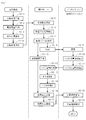
- FIG. 5 is a flowchart showing processing in the battery preparation stage.
- FIG. 6 is a flowchart showing processing when a battery replacement request is made.
- FIG. 7 shows an example of the charging rate determination process.
- FIG. 8 shows an example of the charging speed determination process.
- FIG. 9 shows an example of the charging speed determination process.
- FIG. 10 shows an example of the charging speed determination process.
- FIG. 11 shows an example of the charging rate determination process.
- full charge capacity means the maximum value of the electric capacity of the battery that can be charged at one time. This full charge capacity is proportional to the degree of deterioration of the battery within a specific range. The full charge capacity gradually decreases as the number of times of charging is increased, and rapidly decreases when a certain number of times of charging is exceeded, making it impossible to supply power required by the electric vehicle. When this full charge capacity decreases rapidly, the battery needs to be discarded or replaced.
- the “battery remaining amount” means a remaining amount value of the electric capacity of the battery.
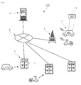
- FIG. 1 is an overall view showing an outline of a battery exchange system 100 for an electric vehicle according to the present invention.
- a system 100 according to the present invention includes a plurality of electric vehicles 2 equipped with replaceable batteries 1, a plurality of battery stations 3 that charge a replacement battery 1, and the entire system.
- a management server 4 that performs management.
- the electric vehicle 2, the battery station 3, and the management server 4 have a configuration capable of exchanging information with each other.
- the electric vehicle 2 includes a communication device that can wirelessly communicate with the communication station 5.
- the battery station 3, the management server 4, and the communication station 5 are connected to each other via an information communication line 6 such as the Internet.
- the electric vehicle 2 travels by driving a motor with electric power supplied from a plurality of batteries 1 mounted on the vehicle.
- Examples of the electric vehicle 2 are an electric vehicle, an electric scooter, an electric assist bicycle, an electric standing motorcycle, and the like.
- the electric vehicle 2 stops at a nearby battery station 3.
- a plurality of batteries 1 are stored and charged.
- the user of the electric vehicle 2 takes out the required number of batteries 1 from the battery station 3 and replaces it with the battery 1 of his / her vehicle. Thereby, the electric vehicle 2 can continue traveling using the charged battery 1.
- the battery station 3 is loaded with the battery 1 having a low remaining battery level. Then, the battery station 3 receives power supply from a power source such as a power network and starts charging the battery 1 loaded therein.
- the user of the electric vehicle 2 can send a battery replacement request to the management server 4 in advance via a communication device provided in the vehicle.
- This battery replacement request includes reservation for battery replacement.
- the management server 4 that has received the battery replacement request notifies the battery station 3 existing within the reachable range of the electric vehicle 2 that the battery replacement request has been made.
- the management server 4 controls the charging speed of the battery 1 in the battery station 3 based on information such as the estimated arrival time of the electric vehicle 2. For example, if the charged battery 1 cannot be prepared before the electric vehicle 2 arrives at the battery station 3 in normal speed charging, the management server 4 instructs the battery station 3 to perform high-speed charging. Send. Thereby, when the electric vehicle 2 arrives at the battery station 3, one or a plurality of charged batteries 1 can be prepared.
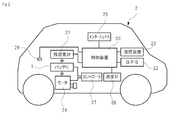
- FIG. 2 is a block diagram showing the configuration of the electric vehicle 2.
- the electric vehicle 2 includes a replaceable battery 1, a control device 20, a remaining capacity meter 21, a position information acquisition device (GPS) 22, a communication device 23, a motor 24, an interface 25, and a speedometer 26. , And a controller 27.
- the electric vehicle 2 is provided with an information connection terminal 28 for taking out information by the control device 20 to the outside as needed.
- the electric vehicle 2 includes an outlet for taking in and out the battery 1.
- the electric vehicle 2 travels by driving the motor 24 via the controller 27 by the replaceable battery 1 and rotating the wheels by the power transmission mechanism.
- the battery 1 a known secondary battery such as a rechargeable nickel-metal hydride battery or a lithium ion battery can be basically used.
- the number of the batteries 1 mounted on the vehicle increases or decreases. That is, the number of the batteries 1 mounted on the electric vehicle 2 may be one or plural.
- the battery 1 supplies power to the motor 24 via the controller 27.
- Each battery 1 used in this system is assigned an identification number (ID).
- ID identification number of each battery 1 is stored in a battery database of the management server 4 to be described later and is centrally managed.
- the battery 1 preferably has a BMS (Battery Management System) 10.
- the BMS 10 may have a different name, but is basically provided inside or outside the battery and is mainly composed of an integrated circuit, a sensor, and the like. It is also preferable that the BMS 10 measures and calculates battery charging information including control of one or a plurality of batteries 1, the remaining battery level, the number of times of charging, and the like. Further, the battery charging information acquired by the BMS 10 may include the number of times of charging, the voltage, current, temperature, and full charge capacity of the battery in addition to the identification number (ID) and the remaining battery level.
- the BMS 10 may have a communication function for communicating battery charging information to the outside.
- the battery charge information such as the identification number and the battery remaining amount acquired from the BMS 10 is the remaining capacity meter 21 mounted on the electric vehicle 2 by wired communication (CAN etc.) or wireless communication (Bluetooth (registered trademark) etc.). It is preferably transmitted to the detector 32 or the like mounted on the battery station 3.
- the control device 20 of the electric vehicle 2 is connected to a remaining capacity meter 21, a position information acquisition device (GPS) 22, a communication device 23, an interface 25, and a speedometer 26, respectively.
- the control device 20 has the battery information including the remaining battery level of the battery 1 acquired from the remaining capacity meter 21, the current position information of the host vehicle acquired by the position information acquisition device (GPS) 22, and the speed.
- the traveling speed of the own vehicle measured by the total 26 can be obtained as appropriate.
- the control device 20 can perform calculation processing on information obtained from various devices, and can transmit it to the management server 4 via the communication device 23. Further, the control device 20 can execute various processes according to input information from the interface 25.
- the control device 20 may be a device provided in the electric vehicle 2 or may use, for example, an information arithmetic processing device provided in a general-purpose portable communication terminal (for example, a smartphone).
- the remaining capacity meter 21 acquires battery charging information including an identification number of the battery 1 mounted on the electric vehicle 2 and a remaining battery level.
- the remaining capacity meter 21 may acquire battery charging information from the BMS 10 included in the battery 1, and when the battery 1 is connected, the identification number of the battery 1, the remaining battery level, and the like are communicated by wired communication (such as CAN) or It may be detected and measured directly via wireless communication (such as Bluetooth (registered trademark)).
- the battery charge information acquired by the remaining capacity meter 21 is output to the control device 20.
- the remaining capacity meter 21 may be a device provided in the electric vehicle 2, or may be a device using an information reception display device provided in a general-purpose portable communication terminal (for example, a smartphone).
- GPS Global Positioning System
- the GPS is a device for measuring the current position of the electric vehicle 2 and obtaining information for specifying the current position.
- the position information acquisition device (GPS) 22 measures the time required to receive each radio wave based on the information on the radio wave transmission time included in the radio waves sent from a plurality of GPS satellites, and indicates the time. Time information is sent to the control device 20.
- the control device 20 can calculate information regarding the latitude and longitude of the location of the electric vehicle 2 based on the acquired time information.
- the position information acquisition device (GPS) 22 is mounted on the electric vehicle 2 included in, for example, a car navigation system (not shown).
- the position information acquisition device (GPS) 22 may be a device provided in the electric vehicle 2, or may be a device using a GPS provided in a general-purpose mobile communication terminal (for example, a smartphone). .
- the communication device 23 is connected to the communication station 5 via a wireless line and can perform bidirectional communication with the management server 4 via the information communication line 6.
- the communication device 23 can transmit information processed by the control device 20 to the management server 4 or can receive information from the management server 4.
- the communication device 23 is included in a car navigation system (not shown) and is mounted on the electric vehicle 2.
- the communication device 23 may be a device provided in the electric vehicle 2, or may be a device using a communication device provided in a general-purpose portable communication terminal (for example, a smartphone).
- the motor 24 converts the electric power obtained from the battery 1 through the controller 27 into a rotational output and transmits it to the power transmission mechanism.
- the electric vehicle 2 travels when the output from the motor 24 is transmitted to the wheels via the power transmission mechanism.
- the interface 25 may be a touch panel display in which a display device and an input device are integrated.
- the speedometer 26 is an instrument that calculates the instantaneous traveling speed of the electric vehicle 2 based on the rotational speed of the motor 24 and the power transmission mechanism or the position information acquisition device (GPS) 22.
- the controller 27 has a function of controlling power supplied from the battery 1 and transmitting it to the motor 24.
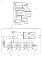
- FIG. 3 is a block diagram showing the configuration of the battery station 3.
- the battery station 3 includes a controller 30, a plurality of chargers 31, a detector 32, a communication device 33, and a power source 34.
- the battery 1 can be loaded in each of the plurality of chargers 31.
- the charger 31 loaded with the battery 1 is supplied with power from the power source 34 according to control by the controller 30 and charges the battery 1.
- the controller 30 of the battery station 3 is connected to a plurality of chargers 31, a detector 32, and a communication device 33. For this reason, the controller 30 can control the charging speed of the battery 1 by the charger 31 based on the control information received from the management server 4 via the communication device 33. Further, the controller 30 can process the detection information acquired by the detector 32 from the battery 1 and transmit it to the management server 4 via the communication device 33.
- the charger 31 is a device that is electrically connected to the battery 1, receives power supply from the power supply 34, and performs a charging operation on the battery 1.
- the charger 31 charges the battery 1 by, for example, a constant current constant voltage method (CC-CV method).
- CC-CV method constant current constant voltage method
- charging is performed at a constant current value from the beginning of charging, and is maintained when the battery voltage reaches a predetermined value as charging progresses.
- the charging current value is continuously reduced.
- the charger 31 can vary the charging speed of the battery 1 in accordance with a control signal from the controller 30.
- the charger 31 can change the charging speed in at least two stages of normal charging that charges at a normal speed and high-speed charging that charges at a higher speed than normal charging.
- the charger 31 may be capable of performing low-speed charging in which charging is performed at a lower speed than normal charging in addition to normal charging and high-speed charging.
- the charging speed and the charging current value are in a substantially proportional relationship. For this reason, the charging speed of the battery 1 can be freely adjusted by controlling the charging current value supplied from the charger 31 to the battery 1.
- the battery 1 has upper limits on the charging speed and the charging current value mainly from the viewpoint of safety and durability.
- charging that is closer to the upper limit of the charging speed and charging current value is faster charging
- charging that is closer to the lower limit of the charging speed and charging current value is slower charging
- charging that is based on the current value between faster charging and slower charging is normal.
- charging at a standard speed within a certain range is called normal charging
- charging faster than normal charging is called fast charging
- charging slower than normal charging is called slow charging.
- the detector 32 is a device for acquiring battery charge information including an identification number and a remaining battery level from the battery 1 in a charged state.
- the detector 32 may acquire battery charging information from the BMS 10 included in the battery 1, and when the battery 1 is connected, the identification number of the battery 1, the remaining battery level, and the like are wired communication (such as CAN). Alternatively, it may be one that directly detects and measures via wireless communication (such as Bluetooth (registered trademark)).
- the remaining battery level of the battery 1 is obtained by, for example, measuring the charge / discharge current value of the battery 1 using the BMS 10 and subtracting the amount of electricity obtained by integrating the current from the remaining capacity (full charge capacity) in the fully charged state. Can be detected.
- the battery charge information detected by the detector 32 is sent to the controller 30.
- the communication device 33 is a device for the battery station 3 to perform bidirectional communication with the management server 4 via the information communication line 6.
- the communication device 33 can transmit information processed by the controller 30 to the management server 4 or receive information from the management server 4.
- the power supply 34 a known power supply can be used as long as it can supply power to the charger 31.
- the power source 34 renewable energy obtained by the natural energy generator 34a may be used.
- the natural energy generator 34a are a solar power generator, a solar power generator, a wind power generator, and the like.
- the natural energy generator 34 a is preferably installed in the vicinity of the battery station 3. That is, the natural energy generator 34a may be mounted on the battery station or may be disposed near the battery station. Further, the battery station may receive power supply from the natural energy generator 34 owned by the power company via the power network. Further, as the power source 34, commercial power supplied from the power network 34b may be used.
- the power source 34 can also use both renewable energy and commercial power.
- the electric power stored in the battery 1 can be sold to the outside through the battery station 3.
- the battery station 3 can sell the electric power stored in the battery 1 to an electric power company, a company, a general household, etc. via an electric power network. It is also possible to sell the power stored in the battery 1 to the user by lending or replacing the battery 1 loaded in the battery station 3.
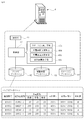
- FIG. 4 is a block diagram showing the configuration of the management server 4.
- the management server 4 includes a control unit 40, a communication unit 41, a battery database 42, an electric vehicle database 43, and a station database 44.
- the management server 4 has a function of controlling this system by centrally managing information on the battery 1, the electric vehicle 2, and the battery station 3.
- the management server 4 may execute these functions by one server device, or may execute these functions by a plurality of server devices.
- the control unit 40 of the management server 4 reads out the program stored in the main memory and performs predetermined arithmetic processing according to the read program.
- the control unit 40 of the management server 4 is connected to a communication unit 41, a battery database 42, an electric vehicle database 43, and a station database 44.
- the control unit 40 records information received from each of the plurality of electric vehicles 2 and the plurality of battery stations 3 via the communication unit 41 in various databases 42, 43, and 44.
- the control unit 40 generates control signals for the electric vehicle 2 and the battery station 4 based on information recorded in the various databases 42, 43, 44, and transmits the control signals via the communication unit 41. be able to.
- the communication unit 41 is a device for the management server 4 to perform bidirectional communication with the electric vehicle 2 and the battery station 3 via the information communication line 6. For example, the communication unit 41 transmits the control signal generated by the control unit 40 toward the electric vehicle 2 and the battery station 3. The communication unit 41 can receive various information transmitted from the electric vehicle 2 and the battery station 3.
- the battery database 42 is storage means for recording management information for each of the plurality of batteries 1 used in the present system.
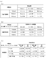
- FIG. 4 shows an example of the data structure of the battery database 42.
- the battery station 42 stores various management information in association with each other using the identification number (ID) of the battery 1 as key information.
- the management information of the battery 1 includes information on the current location of the battery, the number of times of charging, the remaining battery level, the full charge capacity, and the deterioration level. Further, by storing information on a plurality of batteries used in the past in the battery database 42, battery statistical data can be obtained.
- the management server 4 can more accurately grasp the degree of battery deterioration from these pieces of information. .
- the degree of deterioration of the battery can be predicted more accurately by comparing with the past statistical data of a large number of the same type of batteries in addition to the number of times the battery is charged and the full charge capacity.
- the identification number (ID) of the electric vehicle 2 in which the battery is stored and the identification number (ID) of the battery station 3 are recorded. Further, when the electric vehicle 2 or the battery station 3 can store a plurality of batteries, the information on the current location of the battery is stored in any of the plurality of storage locations of the vehicle 2 or the battery station 3. Is preferably information indicating whether or not is stored. In the example shown in FIG. 4, the identification number with the initial “V” is the identification number of the electric vehicle, and the identification number with the initial “S” is the identification number of the battery station. Number.
- information on the number of times the battery has been charged information on the number of times the battery has been stored in the battery station 3 may be recorded, the number of times the battery has been fully charged, or It is good also as recording the frequency
- the method for obtaining the number of times the battery is charged is not limited to the above-described method, and other known methods can be employed.
- information on the number of times the battery is charged is recorded separately for the charging speed, such as the number of times of fast charging, the number of times of normal charging, and the number of times of performing slow charging. It is preferable. By counting the number of times of charging for each charging speed, it is possible to improve the accuracy of calculating the degree of deterioration of the battery.
- the battery charging information including the battery identification number and the remaining battery level
- the rated full charge capacity and the full charge capacity of the battery are recorded.
- the rated full charge capacity is shown in parentheses.
- the full charge capacity may be measured and calculated by the BMS 10.
- the rated full charge capacity (when present) and the full charge capacity corrected by the control unit 40 in consideration of the deterioration of the battery are preferably recorded in the battery database 42. Normally, the more the number of times the battery is used, the smaller the full charge capacity value. At this time, the full charge capacity is preferably a value obtained by correcting the rated full charge capacity based on the number of fast charges, the number of normal charges, and the number of slow charges. Furthermore, there are cases where high-speed charging deteriorates the battery more than normal charging, and normal charging deteriorates the battery more than low-speed charging.
- the full charge capacity by changing the weighting of the degree of influence on the deterioration of the battery according to the fast charge, the normal charge, and the low speed charge.
- the number of fast charge, normal charge, and slow charge of each battery is recorded in the battery database 42, and the full charge capacity is more accurately determined by comparing the record of the number of charges with the past statistical data. Can be guessed.
- the calculation for obtaining the full charge capacity described above is performed by the control unit 40 based on information on the number of times of charging recorded in the battery database 42 and information on the rated full charge capacity.
- the method for obtaining the full charge capacity of the battery is not limited to the method described above, and other known methods can be adopted.
- the information on the degree of deterioration of the battery is calculated by the control unit 40 based on the information recorded in the battery database 42.
- the degree of deterioration may be ranked in five stages from A (new) to E (old). For example, it means that the battery needs to be discarded when the degree of deterioration reaches E rank.
- the control unit 40 can compare the full charge capacities and obtain the degree of deterioration from the rated full charge capacity to the actual full charge capacity as the degree of deterioration.
- the full charge capacity actually measured and calculated from the battery alone by the BMS 10 or the like may vary depending on the external environment and usage load, and accuracy may be low.
- the degree of deterioration corrected based on the number of fast charges, the number of normal charges, and the number of slow charges.
- the number of high-speed charging, normal charging, and low-speed charging of each battery is recorded in the battery database 42, and the degree of deterioration can be estimated more accurately by comparing the number of times of charging with the past statistical data. can do.
- the method for obtaining the degree of deterioration of the battery is not limited to the method described above, and other known methods can be employed.
- the battery database 42 uses the identification number (ID) as key information for each of the plurality of batteries 1, regarding the current location of the battery, the number of times of charging, the remaining battery level, the full charge capacity, and the degree of deterioration. Information is preferably recorded in association with each other.
- ID identification number
- an identification number (ID) for each of the plurality of electric vehicles 2 included in this system, an identification number (ID), personal information of the user (name, address, contact information, etc.), vehicle type, battery usage history
- the transmission history of the battery replacement request is preferably recorded in association with each other.
- Information on the type of vehicle includes information on the type, weight, fuel consumption, and model of the electric vehicle 2.
- the battery usage history includes the identification number (ID) of the battery used in the electric vehicle 2, the identification number (ID) of the battery station that obtained the battery, and the like.
- the transmission history of the battery replacement request includes information such as the number of times the replacement request is transmitted, the location, and the time.
- an identification number (ID), a location, a battery usage history, a battery charging history, and the like are recorded in association with each other for each of the plurality of battery stations 3 included in the present system.
- the battery usage history includes information such as the number of times the battery 1 is removed from the battery station 3, date, date, weather, and identification number of the removed battery 3.
- the battery charging history includes information such as the identification number of the battery that has been charged at the battery station.
- the control unit 40 of the management server 4 preferably includes a station selection unit 40a, an arrival time prediction unit 40b, a charge rate determination unit 40c, and a deterioration degree calculation unit 40d.
- These means 40a, 40b, 40c, 40d, and the control unit 40 are functional blocks that function by reading a program stored in the main memory and executing the read program. These means 40a, 40b, 40c, and 40d will be described in detail according to the processing flow of the system described below.
- FIG. 5 shows a flow when the battery 1 is newly loaded into the battery station 3. That is, the flow shown in FIG. 5 shows a preparation stage process in which the battery 1 is charged by the battery station 3.
- step S1-1 first, one or a plurality of batteries 1 are newly loaded into the battery station 3 (step S1-1).
- the battery 1 loaded in the battery station 3 may be new or used.
- the battery station 3 uses the detector 32 to extract battery charge information including the identification number and the remaining battery level from the battery 1 (step S1-2).
- the battery station 3 transmits battery charging information including the identification number extracted by the detector 32 and the remaining battery level to the management server 4 (step S1-3). Further, the battery station 3 starts charging the newly loaded battery 1 (step S1-4). At this time, the battery station 3 performs normal charging or low-speed charging so that the deterioration of the battery 1 does not proceed even when the remaining amount of the battery 1 is low. That is, at this stage, since the battery station 3 has not received a battery replacement request from the electric vehicle 2, it is not necessary to charge the battery 1 at high speed. Rather, if the battery 1 is charged at a high speed in a stage where the battery replacement request from the electric vehicle 2 is not received, the battery 1 is unnecessarily deteriorated.
- the management server 4 receives the battery charging information including the identification number and the remaining battery level transmitted by the battery station 3 (step S1-5). Thereafter, the control unit 40 of the management server 4 updates the battery database 42 based on the received battery charging information (step S1-6).
- the battery database 42 is preferably updated by updating the remaining location of the battery 1, updating the number of times of charging, updating the remaining battery level, updating the full charge capacity, and updating the degree of deterioration. As described above, it is preferable that the update of the full charge capacity and the deterioration degree is performed by correcting based on the number of times of charging the battery stored in the battery database 42.
- the control unit 40 of the management server 4 may update the charging history recorded in the station database 44 based on the battery charging information received from the battery station 3.
- FIG. 6 shows a flow when a battery replacement request is made from the electric vehicle 2.
- the control device 20 of the electric vehicle 2 generates a request for replacing the battery 1 mounted on the own vehicle (step S2-1).
- the replacement request for the battery 1 may be automatically generated by the control device 20 when the remaining battery level of the battery 1 becomes a predetermined value or less. Further, the battery 1 replacement request may be generated manually by the control device 20 when the user of the electric vehicle 1 performs a predetermined input operation via the interface 25.
- the BMS 10 of the battery 1 measures and calculates the remaining battery capacity of each battery 1 mounted on the host vehicle (step S2-2).
- the battery charge information including the remaining battery level of each battery 1 measured and calculated by the BMS 10 is transmitted to the remaining capacity meter 21 of the electric vehicle 2.
- the remaining capacity meter 21 acquires battery charging information including an identification number and a remaining battery level
- the remaining capacity meter 21 sends the information to the control device 20.
- acquisition of the identification number of each battery 1, a battery remaining amount, etc. may be directly performed by the remaining capacity meter 21.
- the position information acquisition device (GPS) 22 of the electric vehicle 2 detects the current position of the own vehicle (step S2-3). Information on the current position of the electric vehicle 2 detected by the position information acquisition device (GPS) 22 is sent to the control device 20.
- control device 20 When the control device 20 receives the battery charging information including the identification number of the battery 1 and the remaining battery level, and information on the current position of the host vehicle, the control device 20 transmits the information to the management server 4 together with the battery replacement request. (Step S2-5).
- the management server 4 includes a battery replacement request transmitted from the electric vehicle 2, battery charging information including the identification number of the battery 1 mounted on the electric vehicle 2 and the remaining battery level, and information on the current position of the electric vehicle 2, Receive (step S2-6).
- the control unit 40 of the management server 4 may temporarily store these pieces of information received from the electric vehicle 2 in a memory. Further, the control unit of the management server 40 may record the battery replacement request received from the electric vehicle 2 in the electric vehicle database 43.
- the station selection means 40a of the control unit 40 moves the electric vehicle 2 based on the battery charging information and the current position information including the battery identification number and the battery remaining amount received from the electric vehicle 2 for which the battery replacement request is made.
- the possible distance (reachable range) is determined (step S2-6).
- the distance that the electric vehicle 2 can move with a certain amount of battery remaining varies depending on the type of electric vehicle. Therefore, the station selection means 40a refers to, for example, the model of the electric vehicle 2 and determines how far the battery can travel with the remaining battery level. Further, the station selecting means 40a may consider the weather, time zone, road congestion, etc. in determining the reachable range of the electric vehicle 2.
- the station selection means 40a of the control unit 40 selects one or a plurality of battery stations 3 included in the reachable range of the electric vehicle 2 as “candidate stations” (step S2-7).
- the station selection unit 40a may select all the battery stations 3 included in the reachable range of the electric vehicle 2 as candidate stations.
- the station selection means 40a may select only the battery station 3 nearest to the electric vehicle 2.
- the station selecting means 40a extracts a plurality of battery stations 3 included in the reachable range of the electric vehicle 2, and then transmits the locations of the plurality of battery stations 3 to the electric vehicle 2 so that the user of the electric vehicle 2 Alternatively, one battery station 3 may be selected from the plurality of battery stations 3, and the process of selecting one battery station 3 selected by the user as a candidate station may be performed. Moreover, the station selection means 40a is good also as selecting the arbitrary battery stations 3 selected by the operator of this system as a candidate station among the some battery stations 3 included in the reachable range of the electric vehicle 2. .
- the control unit 40 of the management server 4 When a candidate station is selected, the control unit 40 of the management server 4 notifies the selected battery station 3 of that fact (step S2-8). That is, the control unit 40 of the management server 4 notifies the candidate station that there is a possibility that the electric vehicle 2 may stop for battery replacement.
- the battery station 3 selected as the candidate station receives the notification from the management server 4 (step S2-9).
- the battery station 3 (candidate station) that has been notified of the possibility of the electric vehicle 2 dropping in, extracts battery charging information by the detector 32 for a plurality of batteries 1 that are being charged when receiving the notification. .
- the battery charging information extracted here includes the identification number (ID) of the battery 1 and the remaining battery level. Then, the battery station 3 selected as the candidate station transmits the battery charging information extracted by the detector 32 to the management server 4 (step S2-11).
- the management server 4 receives the battery charging information transmitted by the battery station 3 (step S2-12). Thereafter, the deterioration degree calculation means 40d of the management server 4 obtains the deterioration degree of each battery based on the battery charging information received from the battery station 3 and information on the number of times of charging of the battery recorded in the battery database 42 ( Step S2-13). Thereafter, the control unit 40 of the management server 4 updates the battery database 42 to the latest state based on the received battery charging information (step S2-14). As the update operation of the battery database 42 here, it is preferable to update the number of times the battery 1 is charged, update the remaining battery level, update the full charge capacity, and update the degree of deterioration.
- the update of the full charge capacity is performed by correcting based on the number of times of charging the battery stored in the battery database 42.
- the update of the information regarding the degree of deterioration of the battery is based on the degree of deterioration obtained by the deterioration degree calculating means 40d.
- the arrival time predicting means 40b of the control unit 40 provided in the management server 4 has the candidate station selected by the station selecting means 40a, and then the electric vehicle 2 that has requested battery replacement arrives at the candidate station. Is predicted (step S2-15).
- the traveling speed (for example, legal speed) of the electric vehicle 2 varies depending on the type of the electric vehicle. Therefore, the arrival time predicting means 40b refers to, for example, the model of the electric vehicle 2, and predicts the time until the electric vehicle 2 arrives at the candidate station from the position where the battery replacement request is transmitted.
- the arrival time predicting means 40b may take into consideration the weather, time zone, road congestion, and the like when predicting the time when the electric vehicle 2 arrives at the candidate station.
- the charging speed determination unit of the management server 4 40c determines the speed at which the battery 1 is charged in the candidate station based on these pieces of information (step S2-16).
- the charging speed determination unit 40 determines the charging speed of the battery 1 at the candidate station based on the estimated arrival time of the electric vehicle 2 and information recorded in the battery database 42 in consideration of various factors. The charging speed determination process will be described in detail later with reference to FIGS.
- the charging speed determined by the charging speed determination unit 40 is converted into a control signal by the control unit 40 and transmitted to the battery station 3 selected as a candidate station (step S2-17).
- the battery station 3 selected as the candidate station receives the control signal regarding the charging speed transmitted by the management server 4 (step S2-18). Then, the controller 30 of the battery station 3 controls the charging speed of the charger 31 according to the control signal regarding the charging speed received from the management server 4 (step S2-19).
- the management server 4 notifies the electric vehicle 2 of the position of the candidate station at the stage of selecting the candidate station (step S-17) and guides the electric vehicle 2 to the candidate station. It is good also as performing control. Thereby, the electric vehicle 2 can be smoothly guided to the battery station 3 selected as the candidate station. Further, by guiding the electric vehicle, the user of the electric vehicle 2 can move the electric vehicle 2 to the battery station 3 without worrying about running out of the battery.
- the battery delivered from the battery station 3 (candidate station) to the electric vehicle 2 does not always need to be fully charged.
- the driver of the electric vehicle 2 designates a destination that cannot be reached with only one battery (that is, the battery needs to be replaced on the way).
- a battery replacement advance reservation may be made to a plurality of battery stations 3 existing in the destination route of the electric vehicle 2.
- the management server 4 can predict the arrival time of the electric vehicle 2 and control the charging speed of the battery for a plurality of battery stations 3 existing on the route of the electric vehicle 2.
- the battery station 3 where the electric vehicle 2 stops in the middle of the route does not always need to fully charge the battery to be exchanged, and the battery to be exchanged is so far that the electric vehicle 2 can reach the next battery station 3. Charge it.
- the charging speed of the battery by the battery station 3 can be controlled based on various factors.
- FIG. 7A shows an example in which the charging speed of the battery is controlled based on the expected time when the electric vehicle 2 arrives at the battery station 3 and the remaining battery level of the battery charged in the battery station 3. Yes.
- the estimated arrival time may be estimated in consideration of the speed and position of the electric vehicle 2 until the electric vehicle 2 arrives at the candidate station from the position where the battery replacement request is transmitted.
- the estimated arrival time can be obtained in consideration of the weather, time zone, road congestion, and the like. For example, as shown in FIG. 7A, when the estimated arrival time of the electric vehicle 2 is 30 minutes or more and the remaining battery level of the battery charged in the battery station 3 is 90 Ah or more, the battery is , "Slow charging" is enough.
- the battery can be fully charged before the electric vehicle 1 arrives.
- the battery can be fully charged before the electric vehicle 1 arrives.
- the battery is “fast charged”.
- the battery can be fully charged before the electric vehicle 1 arrives.
- the battery is “normally charged”. I am going to do that. The reason for performing such processing is that even if the battery is charged at high speed, it is not in time for the electric vehicle 2 to arrive, so priority is given to prevent the battery from being deteriorated by charging normally.
- the electric vehicle 2 in addition to the estimated arrival time of the electric vehicle 2 and the remaining battery level of the battery charged in the battery station 3, the electric vehicle 2 can travel after reaching the battery station 3 (candidate station).
- the charging speed of the battery is controlled in consideration of a simple distance.
- the distance traveled after the electric vehicle 2 arrives at the candidate station is an index indicating the urgency of battery replacement. That is, if the electric vehicle 2 can travel only a short distance after arriving at the candidate station, it can be said that the urgency to replace the battery of the electric vehicle 2 is high. On the other hand, if the electric vehicle 2 can travel a longer distance after arriving at the candidate station, it can be said that the urgency to replace the battery of the electric vehicle 2 is low.
- the travelable range of the electric vehicle 2 can be calculated in consideration of the remaining battery level of the battery mounted on the electric vehicle 2 and the vehicle type.
- the distance that can be traveled after the electric vehicle 2 arrives at the candidate station can be calculated by subtracting the distance from the electric vehicle 2 to the candidate station from the travelable range of the electric vehicle 2. For example, as shown in FIG. 7B, when it is assumed that the remaining amount of the battery charged in the battery station 3 is 70 Ah, the estimated arrival time of the electric vehicle 2 is within 30 minutes. In the case where the travelable distance after the electric vehicle 2 arrives at the candidate station is within 5 km, the urgency of battery replacement of the electric vehicle 2 is high. For this reason, in such a case, the battery is “fast charged”.
- FIG. 7C shows an example in which the battery replacement timing is predicted from the past use history of the battery station 3 and the battery charging speed is controlled according to the prediction.
- “fast charging” is performed for the time zone, weather, and day of the week when the usage frequency is high
- “slow charging” is performed for the time zone, weather, and day of the week when the usage frequency is low.
- the usage frequency is high when it is sunny or cloudy, and the usage frequency is low when it is raining.
- the usage frequency is high on weekdays and the usage frequency is low on holidays and holidays.
- the usage frequency is high during the morning and evening commuting rush hours, and the usage frequency is low at night.
- the battery replacement timing is predicted from these past usage histories, and “fast charge”, “normal charge”, and “slow charge” of the battery are controlled. Yes.
- FIG. 8 ranks the degree of deterioration of a plurality of batteries charged in the battery station 3, and sets the charging speed of each battery so that the degree of deterioration of each battery in the battery station 3 is leveled.
- An example of control is shown. That is, the battery database 42 included in the management server 4 records the degree of deterioration for each of the plurality of batteries.
- the information regarding the degree of deterioration of the battery is a value determined based on the number of times the battery is charged and information regarding the battery full charge capacity.
- the deterioration degree of the battery 1 being charged is indicated by A to E for a plurality of battery stations 3 within a specific geographical range.
- the degree of deterioration A to E means that “A” is the newest and “E” is the oldest.
- the four battery stations 3 within the specific geographical area shown in FIG. 8 there are many batteries 1 that have a high degree of deterioration and are about to be replaced with new ones. 1 is also present. For this reason, it can be said that it is preferable to suppress the deterioration of the battery 1 by refraining from high-speed charging and performing normal charging or low-speed charging for the relatively old battery 1 having a high degree of deterioration.
- a relatively new battery 1 with a low degree of deterioration is preferably subjected to high-speed charging to promote the deterioration of the battery 1 to match the deterioration degree of other old batteries 1.
- a new battery 1 having a large difference in the degree of deterioration from the other battery 1 is charged relatively frequently so that it is always used preferentially. It is preferable to promote.
- high-speed charging should be avoided as much as possible while preferentially using it. It is preferable to do.
- FIG. 9 shows an example in which the charging speed is controlled so that the remaining battery levels are uniform for a plurality of batteries charged in one battery station 3. That is, such charge speed control is to fully charge any one battery 1 in the same battery station 3 when it is necessary to replace a plurality of batteries 1 for one electric vehicle 2. Instead of giving priority, priority is given to bringing the remaining battery levels of all the batteries 1 close to the same state. This is because, in an electric vehicle driven by a plurality of batteries, the performance (speed and mileage) of the entire vehicle may depend on the performance of the battery that has deteriorated most or the battery that has the least remaining battery level.
- the commercial power supply that supplies power to the battery station 3 is mainly limited in current value (A) and current amount (Ah).
- the current value (A) of normal power supplied from the power grid is limited for each store depending on the content of the contract with the power company.
- FIG. 10 shows an example in which the charger 31 in one battery station 3 can use the battery 1 loaded in the other charger 31 as a power source.
- the remaining battery levels of the plurality of batteries are made uniform. Control the charging speed.
- FIG. 10A shows a case where each charger 31 cannot use the battery 1 loaded in another charger 31 as a power source.
- the amount of current from the external power supply is limited to 25 Ah.
- the remaining amounts of the batteries 1 are 95 Ah, 85 Ah, 70 Ah, and 65 Ah.
- the time until the electric vehicle 1 arrives at the battery station 3 is one hour.
- the remaining battery levels of the four batteries 1 are reduced one hour after the electric vehicle 2 arrives. It is difficult to make uniform.
- the battery 1 with a remaining battery level of 70 Ah is charged with 10 Ah (10 A ⁇ 1 h), and the battery 1 with a remaining battery level of 65 Ah is charged with 15 Ah (15 A ⁇ 1 h).
- the remaining battery levels of the four batteries 1 are 95 Ah, 85 Ah, 80 Ah, and 80 Ah, which cannot be said to be completely uniform.
- FIG. 10B shows a case where each charger 31 can use the battery 1 loaded in another charger 31 as a power source.
- each charger 31 can use the battery 1 loaded in the other charger 31 as a power source. For this reason, it is possible to supply power to the charging of the other battery 1 using the battery 1 charged to 95 Ah having the largest remaining battery capacity as a power source. For example, the current is made to flow backward from the battery 1 charged to 95 Ah by ⁇ 10 Ah ( ⁇ 10 A ⁇ 1 h).
- the electric power supplied from the battery 1 with the remaining battery level 95Ah is utilized for charging the battery 1 with the remaining battery level 70Ah and the battery 1 with the remaining battery level 65Ah.
- the battery 1 with a remaining battery level of 70 Ah can be charged with 15 Ah (15 A ⁇ 1 h)
- the battery 1 with a remaining battery level of 65 Ah can be charged with 20 Ah (20 A ⁇ 1 h).
- the remaining battery levels of the four batteries 1 are all 85 Ah one hour after the electric vehicle 2 arrives, and the remaining battery levels become uniform.
- the remaining battery 1 is charged by using the battery 1 stored in one battery station 3 having a relatively large amount of remaining battery as a power source, thereby realizing uniform battery remaining of each battery 1. It becomes easy.
- FIG. 11 shows an example in which the battery 1 is charged by making maximum use of the renewable energy obtained by the natural energy generator provided in the battery station 3.
- the natural energy generator are a solar power generator, a solar power generator, a wind power generator, and the like.
- the natural energy generator is a solar power generator
- the battery station 3 is provided with a solar power generator
- the battery station 3 is provided with a solar power generator
- the battery station 3 is provided with a solar power generator
- the battery station 3 is provided with a solar power generator
- the battery station 3 is provided with a solar power generator
- the battery station 3 is provided with a solar power generator
- the battery station 3 is provided with a solar power generator
- the battery station 3 is provided with a solar power generator
- the battery station 3 is provided with a solar power generator
- the battery station 3 is provided with a solar power generator
- the battery station 3 is provided with a solar power generator
- the battery station 3 is provided with a solar power generator
- the battery station 3 is provided with a solar
- the solar generator can charge the battery 1 in the solar sunshine time zone (a time zone in which the natural energy generator can generate power), but the solar non-sunshine time zone (natural It is difficult to charge the battery 1 in a time zone in which the energy generator cannot generate power. Furthermore, as described above, it is also required to make the remaining amount of each battery 1 as uniform as possible. Therefore, in the example shown in FIG. 11, in the non-sunshine hours of the sun, the remaining battery level of each battery 1 is obtained by using the battery 1 in the battery station 3 as a power source and charging other batteries. Are made uniform as much as possible, and when the solar sunshine hours are reached, the batteries that have the remaining amount of battery are uniformly charged all at once.
- FIG. 11A shows an example in which the battery 1 is not charged in the non-sunshine hours of the sun.
- the battery station 3 it is assumed that four batteries 1 are stored in the battery station 3 and the remaining amounts of the batteries 1 are 95 Ah, 85 Ah, 75 Ah, and 65 Ah.
- the electric vehicle 2 arrives at the battery station 3 after one hour has passed since the solar sunshine time zone.
- the remaining battery level of the battery 1 in the battery station 3 is not equalized at the time of switching from the non-sunshine time zone to the sunshine time zone, the solar sunshine time zone is reached.
- some batteries may not be fully charged.
- FIG. 11 (a) it is difficult to equalize the remaining battery level of each battery 1 when the electric vehicle 2 arrives even if it is charged for 1 hour after the solar sunshine hours. .
- FIG. 11B shows that the remaining battery level of each battery 1 can be obtained by charging the other battery using the battery 1 in the battery station 3 as a power source even in the non-sunshine hours of the sun. Is to be as uniform as possible.
- a current amount of 15 Ah is supplied from a battery 1 with a remaining battery level of 95 Ah to a battery 1 with a remaining battery level of 65 Ah to be charged.
- a current amount of 5 Ah is supplied from the battery 1 with a remaining battery level of 85 Ah to the battery 1 with a remaining battery level of 75 Ah for charging.
- the battery remaining amount of each battery 1 becomes all 80 Ah and is made uniform. And in the state in which the battery remaining amount of each battery 1 was equalized in this way, it switches from the non-sunshine time zone of the sun to the sunshine time zone. Thereby, charging of the battery 1 is started by the renewable energy obtained from the solar power generator. At this time, since the remaining battery level of each battery 1 is already equalized, the battery 1 is fully charged when the electric vehicle 2 arrives by charging each battery 1 with a current amount of 20 Ah. A plurality of charged batteries 1 can be prepared. As described above, when the battery station 3 includes the solar power generator, the remaining power of each battery 1 is made uniform by using the solar non-sunshine time zone. The renewable energy obtained can be used to the maximum.
- the battery delivered from the battery station 3 (candidate station) to the electric vehicle 2 is not necessarily fully charged.
- the driver of the electric vehicle 2 designates a destination that cannot be reached with only one battery (that is, the battery needs to be replaced on the way).
- a battery replacement advance reservation may be made to a plurality of battery stations 3 existing in the destination route of the electric vehicle 2.
- the management server 4 can predict the arrival time of the electric vehicle 2 and control the charging speed of the battery for a plurality of battery stations 3 existing on the route of the electric vehicle 2.
- the battery station 3 where the electric vehicle 2 stops in the middle of the route does not always need to fully charge the battery to be exchanged, and the battery to be exchanged is so far that the electric vehicle 2 can reach the next battery station 3. Charge it.
- the charging speed of the battery by the battery station 3 can be controlled based on various factors.
- the present invention relates to a battery exchange system for an electric vehicle. Therefore, the present invention can contribute to the realization of a society using clean energy.
Landscapes
- Engineering & Computer Science (AREA)
- Power Engineering (AREA)
- Mechanical Engineering (AREA)
- Transportation (AREA)
- Chemical Kinetics & Catalysis (AREA)
- Chemical & Material Sciences (AREA)
- Manufacturing & Machinery (AREA)
- Electrochemistry (AREA)
- General Chemical & Material Sciences (AREA)
- Business, Economics & Management (AREA)
- Tourism & Hospitality (AREA)
- Sustainable Energy (AREA)
- Sustainable Development (AREA)
- Life Sciences & Earth Sciences (AREA)
- Human Resources & Organizations (AREA)
- Economics (AREA)
- Primary Health Care (AREA)
- Strategic Management (AREA)
- Physics & Mathematics (AREA)
- General Business, Economics & Management (AREA)
- General Physics & Mathematics (AREA)
- Theoretical Computer Science (AREA)
- General Health & Medical Sciences (AREA)
- Marketing (AREA)
- Health & Medical Sciences (AREA)
- Electric Propulsion And Braking For Vehicles (AREA)
- Charge And Discharge Circuits For Batteries Or The Like (AREA)
- Secondary Cells (AREA)
- Navigation (AREA)
- Vehicle Cleaning, Maintenance, Repair, Refitting, And Outriggers (AREA)
- Management, Administration, Business Operations System, And Electronic Commerce (AREA)
Priority Applications (3)
| Application Number | Priority Date | Filing Date | Title |
|---|---|---|---|
| CN202111357827.4A CN114084032B (zh) | 2013-07-04 | 2014-06-11 | 蓄电池交换系统、计算机程序介质、管理伺服器及蓄电池管理方法 |
| CN201810874679.5A CN108973744B (zh) | 2013-07-04 | 2014-06-11 | 蓄电池交换系统、管理伺服器及蓄电池管理方法 |
| CN201480047422.2A CN105493378B (zh) | 2013-07-04 | 2014-06-11 | 电动车辆用蓄电池交换系统及程序 |
Applications Claiming Priority (2)
| Application Number | Priority Date | Filing Date | Title |
|---|---|---|---|
| JP2013-140925 | 2013-07-04 | ||
| JP2013140925A JP5362930B1 (ja) | 2013-07-04 | 2013-07-04 | 電動車両用バッテリ交換システム及びプログラム |
Publications (1)
| Publication Number | Publication Date |
|---|---|
| WO2015001930A1 true WO2015001930A1 (ja) | 2015-01-08 |
Family
ID=49850344
Family Applications (1)
| Application Number | Title | Priority Date | Filing Date |
|---|---|---|---|
| PCT/JP2014/065458 Ceased WO2015001930A1 (ja) | 2013-07-04 | 2014-06-11 | 電動車両用バッテリ交換システム及びプログラム |
Country Status (4)
| Country | Link |
|---|---|
| JP (4) | JP5362930B1 (enExample) |
| CN (4) | CN108749624B (enExample) |
| TW (1) | TWI583577B (enExample) |
| WO (1) | WO2015001930A1 (enExample) |
Cited By (37)
| Publication number | Priority date | Publication date | Assignee | Title |
|---|---|---|---|---|
| JP2016170771A (ja) * | 2015-03-09 | 2016-09-23 | パナソニックIpマネジメント株式会社 | 貸与システムおよび貸与管理方法 |
| JP2017023366A (ja) * | 2015-07-22 | 2017-02-02 | ジーイー・メディカル・システムズ・グローバル・テクノロジー・カンパニー・エルエルシー | システム |
| JP2017091430A (ja) * | 2015-11-17 | 2017-05-25 | オムロン株式会社 | 誘導装置、誘導システムおよび誘導方法 |
| CN106787830A (zh) * | 2016-12-19 | 2017-05-31 | 深圳惠养车科技有限公司 | 一种汽车保养站集成电源管理系统 |
| JP2017103897A (ja) * | 2015-12-01 | 2017-06-08 | オムロン株式会社 | バッテリ充電装置、バッテリ充電システムおよびバッテリ充電方法 |
| TWI601085B (zh) * | 2017-02-24 | 2017-10-01 | Mobile power exchange system and method thereof | |
| US9883787B2 (en) | 2014-06-19 | 2018-02-06 | Olympus Corporation | Medical apparatus system |
| EP3249601A4 (en) * | 2015-03-12 | 2018-02-07 | Omron Corporation | Information processing device, control method for same, control program, and recording medium |
| WO2018079590A1 (ja) * | 2016-10-26 | 2018-05-03 | 京セラ株式会社 | 管理システム、自転車、制御方法及び記憶媒体 |
| JP2018073006A (ja) * | 2016-10-26 | 2018-05-10 | 京セラ株式会社 | 管理システム及び自転車 |
| FR3063954A1 (fr) * | 2017-03-17 | 2018-09-21 | Arkod Innovation | Systeme d'infrastructure de charge et distribution d'unites amovibles autonomes de stockage d'energie pour vehicules electroniques et hybrides |
| EP3379467A4 (en) * | 2015-11-17 | 2018-12-19 | Omron Corporation | Battery reservation device and battery reservation method |
| EP3379464A4 (en) * | 2015-11-17 | 2019-01-02 | Omron Corporation | Battery reservation device |
| CN109642802A (zh) * | 2016-09-30 | 2019-04-16 | 本田技研工业株式会社 | 路径搜索装置、电池信息管理装置以及程序 |
| CN110015165A (zh) * | 2017-07-31 | 2019-07-16 | 周锡卫 | 一种适于人工换电的直流主动调控储能蓄电池模块及控制方法 |
| CN110435456A (zh) * | 2018-05-02 | 2019-11-12 | 爱驰汽车有限公司 | 可替换电池包的电动车充电方法、系统、设备及存储介质 |
| WO2020004509A1 (ja) | 2018-06-29 | 2020-01-02 | レスク株式会社 | バッテリ管理システム |
| US10600116B2 (en) | 2015-11-17 | 2020-03-24 | Omron Corporation | Reservation management device, reservation management system, and reservation management method |
| EP3564061A4 (en) * | 2016-12-30 | 2020-07-08 | NIO Nextev Limited | METHOD AND DEVICE FOR DETERMINING THE UTILITY OF A BATTERY PACK REPLACEMENT FOR AN ELECTRIC VEHICLE |
| CN111868477A (zh) * | 2018-03-23 | 2020-10-30 | 本田技研工业株式会社 | 服务管理系统、信息处理装置、服务管理方法、终端装置以及移动电池 |
| US11010824B2 (en) | 2015-11-17 | 2021-05-18 | Omron Corporation | Battery reservation device and battery reservation method |
| CN113169384A (zh) * | 2018-11-29 | 2021-07-23 | 本田技研工业株式会社 | 电池利用系统、充电装置、信息处理装置、电池利用方法、程序及存储介质 |
| US11136008B2 (en) | 2017-12-29 | 2021-10-05 | Gogoro Inc. | Systems and methods for managing exchangeable energy storage device stations |
| US11379899B2 (en) | 2015-03-27 | 2022-07-05 | Panasonic Intellectual Property Management Co., Ltd. | Control method of information terminal |
| US20220245234A1 (en) * | 2019-07-17 | 2022-08-04 | Gogoro Inc. | Systems and methods for managing batteries |
| CN114851872A (zh) * | 2021-02-04 | 2022-08-05 | 福建途柚新能源汽车集团股份有限公司 | 一种兼容新能源汽车、电动自行车的动力电池和换电装置 |
| JP2023003719A (ja) * | 2021-06-24 | 2023-01-17 | トヨタ自動車株式会社 | ロボット管理システム、ロボット管理方法、及びプログラム |
| WO2023039561A1 (en) * | 2021-09-10 | 2023-03-16 | Land Energy, Inc | Battery-centric virtual grid (vg) system |
| CN115871609A (zh) * | 2022-12-19 | 2023-03-31 | 蓝谷智慧(北京)能源科技有限公司 | 换电站及其充电控制系统和充电控制方法 |
| EP4246658A1 (en) * | 2022-03-16 | 2023-09-20 | Toyota Jidosha Kabushiki Kaisha | Battery management system |
| US11797290B2 (en) | 2018-12-04 | 2023-10-24 | Mitsubishi Electric Corporation | Update control device and update control method |
| WO2023211377A1 (en) * | 2022-04-25 | 2023-11-02 | Sun Mobility Pte Ltd | Systems and methods for optimized and intelligent charging of battery packs at a battery charging and swapping station |
| EP4276717A1 (en) * | 2022-05-11 | 2023-11-15 | Hitachi, Ltd. | Information processing apparatus, energy system, and battery operation plan creation method |
| US11841382B2 (en) | 2018-03-20 | 2023-12-12 | Honda Motor Co., Ltd. | Information providing apparatus, information providing method, and system |
| JP2024501869A (ja) * | 2020-12-31 | 2024-01-16 | 奥動新能源汽車科技有限公司 | オフステーション充電制御方法、システム、電子機器及び記憶媒体 |
| US20240176777A1 (en) * | 2022-06-21 | 2024-05-30 | Rivian Ip Holdings, Llc | Systems and methods for updating electric charger locations |
| US12087961B2 (en) | 2021-09-10 | 2024-09-10 | Land Energy, Inc | Battery-centric virtual grid (VG) system |
Families Citing this family (109)
| Publication number | Priority date | Publication date | Assignee | Title |
|---|---|---|---|---|
| US9727511B2 (en) | 2011-12-30 | 2017-08-08 | Bedrock Automation Platforms Inc. | Input/output module with multi-channel switching capability |
| US10834094B2 (en) | 2013-08-06 | 2020-11-10 | Bedrock Automation Platforms Inc. | Operator action authentication in an industrial control system |
| US12061685B2 (en) | 2011-12-30 | 2024-08-13 | Analog Devices, Inc. | Image capture devices for a secure industrial control system |
| US10834820B2 (en) | 2013-08-06 | 2020-11-10 | Bedrock Automation Platforms Inc. | Industrial control system cable |
| US9600434B1 (en) | 2011-12-30 | 2017-03-21 | Bedrock Automation Platforms, Inc. | Switch fabric having a serial communications interface and a parallel communications interface |
| US9191203B2 (en) | 2013-08-06 | 2015-11-17 | Bedrock Automation Platforms Inc. | Secure industrial control system |
| US8862802B2 (en) | 2011-12-30 | 2014-10-14 | Bedrock Automation Platforms Inc. | Switch fabric having a serial communications interface and a parallel communications interface |
| US11314854B2 (en) | 2011-12-30 | 2022-04-26 | Bedrock Automation Platforms Inc. | Image capture devices for a secure industrial control system |
| US9467297B2 (en) | 2013-08-06 | 2016-10-11 | Bedrock Automation Platforms Inc. | Industrial control system redundant communications/control modules authentication |
| US11967839B2 (en) | 2011-12-30 | 2024-04-23 | Analog Devices, Inc. | Electromagnetic connector for an industrial control system |
| US9437967B2 (en) | 2011-12-30 | 2016-09-06 | Bedrock Automation Platforms, Inc. | Electromagnetic connector for an industrial control system |
| US8971072B2 (en) | 2011-12-30 | 2015-03-03 | Bedrock Automation Platforms Inc. | Electromagnetic connector for an industrial control system |
| US10613567B2 (en) | 2013-08-06 | 2020-04-07 | Bedrock Automation Platforms Inc. | Secure power supply for an industrial control system |
| CN111293495B (zh) | 2014-07-07 | 2022-05-24 | 基岩自动化平台公司 | 工业控制系统电缆 |
| WO2016006057A1 (ja) * | 2014-07-09 | 2016-01-14 | 三菱電機株式会社 | 電力授受システムおよび電力授受方法 |
| WO2016036742A1 (en) * | 2014-09-04 | 2016-03-10 | Gogoro Inc. | Apparatus, system, and method for vending, charging, and two-way distribution of electrical energy storage devices |
| KR101682788B1 (ko) * | 2015-01-28 | 2016-12-12 | 중소기업은행 | 전기자동차의 배터리 교환 시스템 및 방법 |
| US9772383B2 (en) | 2015-03-04 | 2017-09-26 | Johnson Controls Technology Company | Battery test report system and method |
| CN113741373A (zh) * | 2015-04-13 | 2021-12-03 | 基岩自动化平台公司 | 用于工业控制系统的安全电源 |
| CN107069840B (zh) * | 2016-02-10 | 2022-05-27 | 松下知识产权经营株式会社 | 蓄电装置及其控制方法、充电装置及其控制方法以及无线连接设定系统 |
| CN105529787A (zh) * | 2016-02-24 | 2016-04-27 | 北京新能源汽车股份有限公司 | 充电桩 |
| KR101748085B1 (ko) * | 2016-06-01 | 2017-06-16 | 공현규 | 무인이동장치를 이용한 전력공급방법 |
| KR101864483B1 (ko) * | 2016-06-17 | 2018-06-04 | 이남재 | 전기차 배터리 교환 시스템 및 방법 |
| CN107972499A (zh) * | 2016-10-21 | 2018-05-01 | 法乐第(北京)网络科技有限公司 | 一种动力电池管理系统和包括其的电动汽车 |
| JP6687499B2 (ja) * | 2016-11-01 | 2020-04-22 | 本田技研工業株式会社 | 情報処理装置 |
| CN106683280B (zh) * | 2016-12-30 | 2019-03-26 | 哈尔滨理工大学 | 一种用于电动车电池交换续航及充电的控制装置 |
| CN108448661A (zh) * | 2017-02-16 | 2018-08-24 | 林文德 | 电池交换系统以及电池交换方法 |
| JP6345291B1 (ja) | 2017-03-22 | 2018-06-20 | 本田技研工業株式会社 | 情報処理装置、プログラム及び情報処理方法 |
| JP6345292B1 (ja) * | 2017-03-22 | 2018-06-20 | 本田技研工業株式会社 | 管理装置、プログラム、管理方法及び生産方法 |
| JP6363754B1 (ja) | 2017-03-22 | 2018-07-25 | 本田技研工業株式会社 | 情報処理装置、プログラム及び情報処理方法 |
| JP2019023600A (ja) * | 2017-07-25 | 2019-02-14 | 株式会社Jvcケンウッド | 管理装置、端末装置および通信システム |
| DE102017216127A1 (de) * | 2017-09-13 | 2019-03-14 | Audi Ag | Verfahren zum Bereitstellen einer Kommunikationsverbindung zwischen einer stationären elektrischen Ladestation und einem Kraftfahrzeug sowie Steuervorrichtung und Ladesystem |
| US11557906B2 (en) * | 2017-09-22 | 2023-01-17 | The Noco Company | Rechargeable battery jump starting device with control switch backlight system |
| WO2019065321A1 (ja) * | 2017-09-29 | 2019-04-04 | 本田技研工業株式会社 | マガジン式充電装置 |
| JP6595036B2 (ja) * | 2017-09-29 | 2019-10-23 | 本田技研工業株式会社 | マガジン式充電装置 |
| WO2019093082A1 (ja) | 2017-11-10 | 2019-05-16 | パナソニックIpマネジメント株式会社 | 充電装置 |
| JP6846667B2 (ja) | 2017-11-10 | 2021-03-24 | パナソニックIpマネジメント株式会社 | 充填体収容装置 |
| JP2019097235A (ja) * | 2017-11-18 | 2019-06-20 | 渡邉 雅弘 | 再生可能エネルギー蓄積および利用方法 |
| JP7032110B2 (ja) * | 2017-11-21 | 2022-03-08 | トヨタ自動車株式会社 | 交換料金設定装置および交換料金設定システム |
| CN110015105A (zh) * | 2017-12-18 | 2019-07-16 | 陈志勇 | 充电站系统 |
| TWI741245B (zh) * | 2017-12-29 | 2021-10-01 | 英屬開曼群島商睿能創意公司 | 管理位於裝置交換站中的儲能裝置的系統和方法 |
| JP2019145088A (ja) * | 2017-12-29 | 2019-08-29 | ゴゴロ インク | 交換可能エネルギー貯蔵装置ステーション間でエネルギーを動的に配分するためのシステムおよび方法 |
| TWI704740B (zh) * | 2017-12-29 | 2020-09-11 | 英屬開曼群島商睿能創意公司 | 提供置於裝置交換站的複數個能源儲存裝置的方法、裝置交換站及伺服器 |
| TWI740082B (zh) | 2017-12-29 | 2021-09-21 | 英屬開曼群島商睿能創意公司 | 對置於裝置交換站的複數個可交換式能源儲存裝置的充電方法、伺服器、裝置交換站的管理方法 |
| JP6907345B2 (ja) * | 2018-01-29 | 2021-07-21 | 本田技研工業株式会社 | 情報処理システム、情報処理装置、および情報処理方法 |
| KR102131287B1 (ko) * | 2018-01-30 | 2020-07-07 | 재상전자주식회사 | 전기이륜차의 배터리 교환 시스템 |
| JP6951543B2 (ja) * | 2018-02-13 | 2021-10-20 | 本田技研工業株式会社 | 制御装置、制御方法、及びプログラム |
| US11648845B2 (en) | 2018-02-23 | 2023-05-16 | Panasonic Intellectual Property Management Co., Ltd. | Battery managing system, battery managing method, and terminal device |
| TWI694936B (zh) * | 2018-03-02 | 2020-06-01 | 光陽工業股份有限公司 | 充電電池的預約方法及電動載具系統 |
| TWI653597B (zh) | 2018-03-02 | 2019-03-11 | 光陽工業股份有限公司 | 供電裝置交換方法及其銷售端行動裝置 |
| TWI669677B (zh) * | 2018-03-07 | 2019-08-21 | 光陽工業股份有限公司 | 充電座管理方法、用於充電座管理方法的伺服器及充電座 |
| TWI685765B (zh) * | 2018-03-07 | 2020-02-21 | 光陽工業股份有限公司 | 供電裝置之載具綁定變更方法及其伺服器 |
| WO2019182303A1 (ko) * | 2018-03-19 | 2019-09-26 | 엘지전자 주식회사 | 휴대용 배터리 충전 시스템 |
| JP2019165584A (ja) * | 2018-03-20 | 2019-09-26 | 本田技研工業株式会社 | 情報提供装置、情報提供方法及びシステム |
| JP2021119555A (ja) * | 2018-03-20 | 2021-08-12 | 本田技研工業株式会社 | 管理装置、バッテリおよび管理システム |
| WO2019181584A1 (ja) * | 2018-03-20 | 2019-09-26 | 本田技研工業株式会社 | 管理装置および管理システム |
| CN111670451A (zh) * | 2018-03-20 | 2020-09-15 | 本田技研工业株式会社 | 服务器、管理装置及管理系统 |
| JP7016947B2 (ja) * | 2018-03-20 | 2022-02-07 | 本田技研工業株式会社 | 管理装置および管理システム |
| JPWO2019181702A1 (ja) * | 2018-03-20 | 2020-12-17 | 本田技研工業株式会社 | 管理装置および管理システム |
| US11447105B2 (en) * | 2018-03-29 | 2022-09-20 | Gogoro Inc. | Systems and methods for managing batteries in a battery exchange station |
| US20190337392A1 (en) * | 2018-05-02 | 2019-11-07 | Baker Hughes, A Ge Company, Llc | Storing and Providing Electric Energy to Equipment |
| DE102018005252A1 (de) * | 2018-07-02 | 2020-01-02 | Daimler Ag | Verfahren zum Betrieb eines Fahrzeugs |
| WO2020054171A1 (ja) * | 2018-09-13 | 2020-03-19 | 本田技研工業株式会社 | 配置計画装置 |
| CN109249837B (zh) * | 2018-09-28 | 2021-03-02 | 汉海信息技术(上海)有限公司 | 电池更换方法、服务器、充电柜及系统 |
| JP2020077521A (ja) * | 2018-11-07 | 2020-05-21 | パナソニックIpマネジメント株式会社 | バッテリステーション管理システム及びバッテリステーション管理方法 |
| US20220021220A1 (en) * | 2018-11-29 | 2022-01-20 | Honda Motor Co., Ltd. | Battery utilization system, storing device, battery utilization method, program, and storage medium |
| KR102171604B1 (ko) * | 2018-11-30 | 2020-10-29 | 주식회사 젠트로피 | 전기이륜차의 배터리교환 자동 예약 시스템 및 방법 |
| KR102190351B1 (ko) * | 2018-11-30 | 2020-12-11 | 재상전자주식회사 | 전기이륜차의 배터리 교환 시스템 및 방법 |
| US11374421B2 (en) | 2018-12-05 | 2022-06-28 | Neutron Holdings, Inc. | Rechargeable battery kiosk that dynamically alters a charging rate of rechargeable batteries based on usage data |
| JP7486470B2 (ja) * | 2019-02-18 | 2024-05-17 | 本田技研工業株式会社 | 保管装置、推定装置、保管方法、プログラム、及び記憶媒体 |
| JP7399152B2 (ja) * | 2019-02-25 | 2023-12-15 | 本田技研工業株式会社 | 移動体、バッテリ、情報処理方法、およびプログラム |
| KR102281641B1 (ko) * | 2019-04-01 | 2021-07-29 | 스마트큐브(주) | 스마트폰을 이용한 전기운송수단용 배터리 관제시스템 |
| CN110001450A (zh) * | 2019-04-19 | 2019-07-12 | 桂林市小蜗科技有限公司 | 一种电动汽车和电动单车混合交流充电桩 |
| CN110077270B (zh) * | 2019-05-09 | 2021-11-02 | 重庆九环新越新能源科技发展有限公司 | 储能设备的集中充/集电方法及系统 |
| CN110103769B (zh) * | 2019-06-26 | 2021-02-19 | 广州小鹏汽车科技有限公司 | 电动车辆的充电控制方法、装置、存储介质及计算机设备 |
| EP3761717A1 (en) | 2019-07-05 | 2021-01-06 | Sony Corporation | Server devices, machines, battery devices and methods for managing usage of one or more battery devices |
| CN112487308B (zh) * | 2019-09-12 | 2024-02-20 | 奥动新能源汽车科技有限公司 | 换电站的查找方法及系统 |
| CN114730445A (zh) * | 2019-11-19 | 2022-07-08 | 本田技研工业株式会社 | 信息处理装置、程序和信息处理方法 |
| US12311989B2 (en) | 2019-11-19 | 2025-05-27 | Mitsubishi Electric Corporation | Maintenance management system and maintenance management ground system |
| CN111003088B (zh) * | 2019-11-27 | 2021-05-14 | 安徽科创生产力促进中心有限公司 | 一种电动自行车电池架及其换电装置 |
| JP7075919B2 (ja) * | 2019-12-23 | 2022-05-26 | 本田技研工業株式会社 | バッテリ情報提供装置、バッテリ情報提供システム、バッテリ情報提供方法、およびプログラム |
| CN114946101A (zh) * | 2020-01-17 | 2022-08-26 | 松下电器(美国)知识产权公司 | 电池数据管理方法、电池数据管理系统及程序 |
| US20230048253A1 (en) * | 2020-01-24 | 2023-02-16 | Gs Yuasa International Ltd. | Determination device, deterioration determination system, work support device, deterioration determination method, and computer program |
| JP7062022B2 (ja) * | 2020-02-18 | 2022-05-02 | 本田技研工業株式会社 | 経路案内装置及びプログラム |
| JP7420596B2 (ja) * | 2020-03-04 | 2024-01-23 | 古河電気工業株式会社 | 充電システム |
| JP7716385B2 (ja) * | 2020-03-19 | 2025-07-31 | 本田技研工業株式会社 | 制御装置、充電装置、制御方法、温度調節方法、プログラム、及び、コンピュータ可読記録媒体 |
| WO2021194267A1 (ko) * | 2020-03-24 | 2021-09-30 | 주식회사 엘지에너지솔루션 | 전기차 충전 스테이션을 이용한 배터리 성능관리 시스템 및 방법 |
| WO2021241764A1 (ja) * | 2020-05-29 | 2021-12-02 | 本田技研工業株式会社 | 情報取得装置、情報処理システム、推定装置、情報取得方法、推定方法、制御方法、プログラム、及び、コンピュータ可読記録媒体 |
| CN114079091B (zh) * | 2020-08-11 | 2023-05-12 | 宇通客车股份有限公司 | 一种电池系统编码成组方法 |
| CN115151922A (zh) * | 2020-08-27 | 2022-10-04 | 株式会社Lg新能源 | 集成电池管理平台服务系统和方法 |
| KR102788412B1 (ko) | 2020-10-27 | 2025-03-27 | 주식회사 엘지에너지솔루션 | 배터리 분배 장치 |
| KR102283832B1 (ko) * | 2021-01-25 | 2021-08-02 | (주)블루네트웍스 | 복수의 스테이션별 이동식 충전배터리 풀을 관리하는 방법 및 서버 |
| JP7577560B2 (ja) * | 2021-02-15 | 2024-11-05 | 本田技研工業株式会社 | サーバ装置 |
| EP4170572B1 (en) | 2021-08-31 | 2025-01-29 | Contemporary Amperex Technology (Hong Kong) Limited | Battery swapping method, apparatus and system, and device and medium |
| KR102916569B1 (ko) * | 2021-09-03 | 2026-01-22 | 주식회사 엘지에너지솔루션 | 배터리 충전 장치 및 배터리 관리 장치 |
| KR20230037096A (ko) | 2021-09-08 | 2023-03-16 | 주식회사 엘지에너지솔루션 | 배터리 교환 장치, 배터리 상태 진단 서버 장치 및 방법, 그리고 이를 포함하는 배터리 교환 시스템 |
| EP4399782A1 (en) * | 2021-09-10 | 2024-07-17 | Land Energy, Inc | Home plus vehicle battery backup system with individual battery module profiles |
| KR20230043423A (ko) * | 2021-09-24 | 2023-03-31 | 주식회사 엘지에너지솔루션 | 비상발전기능을 갖는 배터리 교체 스테이션 |
| WO2023047540A1 (ja) * | 2021-09-24 | 2023-03-30 | 本田技研工業株式会社 | バッテリーステーション及び制御方法 |
| TWI796801B (zh) * | 2021-10-07 | 2023-03-21 | 國立虎尾科技大學 | 電動載具的使用記錄系統 |
| KR20230059947A (ko) * | 2021-10-26 | 2023-05-04 | 주식회사 엘지에너지솔루션 | 배터리 교환 스테이션 및 이를 이용한 배터리 충전 방법 |
| CN116416083B (zh) * | 2021-12-30 | 2024-08-06 | 奥动新能源汽车科技有限公司 | 电池的管理方法、装置、电子设备、存储介质 |
| JP7799032B2 (ja) * | 2022-03-16 | 2026-01-14 | 本田技研工業株式会社 | 管理サーバ、その制御方法及びバッテリ充電システム |
| JP7469501B1 (ja) * | 2022-05-20 | 2024-04-16 | 日揮ホールディングス株式会社 | バッテリーユニット保管用倉庫 |
| WO2024029034A1 (ja) * | 2022-08-04 | 2024-02-08 | 本田技研工業株式会社 | 情報処理装置、情報処理システム、情報処理方法およびプログラム |
| JP2024041503A (ja) * | 2022-09-14 | 2024-03-27 | カワサキモータース株式会社 | バッテリ管理方法、記憶制御装置、移動体、およびサーバ |
| JPWO2024111017A1 (enExample) * | 2022-11-21 | 2024-05-30 | ||
| WO2025126385A1 (ja) * | 2023-12-13 | 2025-06-19 | 日本たばこ産業株式会社 | 制御装置、制御方法及びプログラム |
| CN118917822B (zh) * | 2024-07-02 | 2025-04-15 | 国网湖北省电力有限公司咸宁供电公司 | 一种移动检修电源集群管理系统 |
Citations (10)
| Publication number | Priority date | Publication date | Assignee | Title |
|---|---|---|---|---|
| JPH0648184A (ja) * | 1992-06-16 | 1994-02-22 | Hans Baer | 電気自動車へのエネルギー供給方法及び装置並びにその供給に適した自動車 |
| JPH10285824A (ja) * | 1997-04-11 | 1998-10-23 | Matsushita Electric Ind Co Ltd | 非常用発電装置 |
| JP2001057711A (ja) * | 1999-01-25 | 2001-02-27 | Zip Charge:Kk | 電気車両用エネルギー供給システム、電気車両用バッテリ、電気車両用バッテリ充電装置、バッテリ販売装置及び電気車両用バッテリ管理システム |
| JP2002313433A (ja) * | 2001-04-18 | 2002-10-25 | Makita Corp | 複数の充電装置の管理方法 |
| JP2010175492A (ja) * | 2009-02-02 | 2010-08-12 | Omron Corp | 情報処理端末、情報処理装置、情報処理システム、情報処理方法、および、プログラム |
| JP2011083166A (ja) * | 2009-10-09 | 2011-04-21 | Chugoku Electric Power Co Inc:The | 充電スタンド案内システム、制御サーバ及びスタンドサーバ |
| JP2012048286A (ja) * | 2010-08-24 | 2012-03-08 | Hitachi Ltd | 電気自動車の充電制御方法、充電監視制御センタ、車載カーナビ装置、および電力系統安定化システム |
| WO2012120564A1 (ja) * | 2011-03-09 | 2012-09-13 | 株式会社 日立製作所 | 二次電池システム |
| JP2012253976A (ja) * | 2011-06-06 | 2012-12-20 | Shimizu Corp | 充放電制御装置、充放電制御方法、プログラム |
| JP2013121303A (ja) * | 2011-12-09 | 2013-06-17 | Toyota Industries Corp | 電池充電量制御装置および方法 |
Family Cites Families (37)
| Publication number | Priority date | Publication date | Assignee | Title |
|---|---|---|---|---|
| JP3715089B2 (ja) * | 1997-09-15 | 2005-11-09 | 本田技研工業株式会社 | バッテリ充電装置 |
| CN1459396A (zh) * | 2002-05-23 | 2003-12-03 | 刘奥宇 | 电动车电能供应站 |
| US7282891B2 (en) * | 2002-12-30 | 2007-10-16 | Motorola, Inc. | Method for charging a battery |
| JP2004215468A (ja) * | 2003-01-09 | 2004-07-29 | Oki Electric Ind Co Ltd | 二次電池電源供給方法及びその通信システム並びにプログラム |
| CN1439544A (zh) * | 2003-03-28 | 2003-09-03 | 潘世澄 | 一种延长电动车辆续行距离的方法 |
| JP2005006461A (ja) * | 2003-06-13 | 2005-01-06 | Panasonic Ev Energy Co Ltd | 無人搬送車用二次電池の充放電制御方法 |
| CN100517905C (zh) * | 2004-11-18 | 2009-07-22 | 上海磁浮交通工程技术研究中心 | 基于混沌控制的车载蓄电池管理方法 |
| US8117293B1 (en) * | 2005-01-05 | 2012-02-14 | Smith Micro Software, Inc. | Method of receiving, storing, and providing device management parameters and firmware updates to application programs within a mobile device |
| JP2007116799A (ja) * | 2005-10-19 | 2007-05-10 | Leben Hanbai:Kk | バッテリー管理システム |
| JP5228322B2 (ja) * | 2006-08-30 | 2013-07-03 | トヨタ自動車株式会社 | 蓄電装置の劣化評価システム、車両、蓄電装置の劣化評価方法およびその劣化評価方法をコンピュータに実行させるためのプログラムを記録したコンピュータ読取可能な記録媒体 |
| WO2010005052A2 (ja) * | 2008-07-10 | 2010-01-14 | Ishii Mitoshi | 電気自動車の蓄電池の管理方法 |
| US8006793B2 (en) * | 2008-09-19 | 2011-08-30 | Better Place GmbH | Electric vehicle battery system |
| EP2323866A2 (en) * | 2008-09-19 | 2011-05-25 | Better Place GmbH | System and method for operating an electric vehicle |
| JP5338337B2 (ja) * | 2009-01-23 | 2013-11-13 | 日産自動車株式会社 | バッテリ交換システム及びバッテリ交換方法 |
| DE102009016869A1 (de) * | 2009-04-08 | 2010-10-14 | Li-Tec Battery Gmbh | Verfahren zum Betreiben eines Fahrzeugs |
| US8676636B2 (en) * | 2009-04-22 | 2014-03-18 | Parkpod Gmbh | System for managing electric energy grid-vehicle exchange devices |
| CN102474110B (zh) * | 2009-07-15 | 2014-12-10 | 松下电器产业株式会社 | 电力控制系统、电力控制方法、电力控制装置及电力控制程序 |
| JP2011041441A (ja) * | 2009-08-18 | 2011-02-24 | Toyota Central R&D Labs Inc | 充電電力制限値演算装置 |
| WO2011034526A1 (en) * | 2009-09-16 | 2011-03-24 | Jonathan Matthew Ross | Battery management method and system |
| JP2011087430A (ja) * | 2009-10-16 | 2011-04-28 | Toyota Motor Corp | 充電装置および充電方法 |
| JP4998544B2 (ja) * | 2009-12-25 | 2012-08-15 | トヨタ自動車株式会社 | 交換用蓄電装置の管理システムおよび交換用蓄電装置の管理方法 |
| JP2011147308A (ja) * | 2010-01-18 | 2011-07-28 | Toyota Motor Corp | バッテリの充電システム |
| JP2011155737A (ja) * | 2010-01-26 | 2011-08-11 | Toyota Motor Corp | バッテリの充電システム |
| JP2011155765A (ja) * | 2010-01-27 | 2011-08-11 | Toyota Motor Corp | 充電装置および充電方法 |
| US8427104B2 (en) * | 2010-04-22 | 2013-04-23 | The Raymond Corporation | Method of allocating batteries for use on specific industrial vehicles in a fleet |
| JP2011234599A (ja) * | 2010-04-26 | 2011-11-17 | Hisashi Tsukamoto | 走行体運行システム |
| EP2385349A1 (en) * | 2010-05-06 | 2011-11-09 | Leica Geosystems AG | Method and guidance unit for guiding battery-operated transportation means to reconditioning stations |
| CN102959418B (zh) * | 2010-06-24 | 2016-04-27 | 松下知识产权经营株式会社 | 获取电池的劣化度的方法和系统 |
| JP5544499B2 (ja) * | 2010-07-12 | 2014-07-09 | アルプス・グリーンデバイス株式会社 | バッテリ充電システム及びバッテリ充電方法 |
| DE102011086903A1 (de) * | 2010-11-25 | 2012-05-31 | Denso Corporation | Fahrzeugelektrizitätsbedarfsschätzvorrichtung, elektrizitätsinformationsverarbeitungsvorrichtung und ladesystem |
| CN102064578B (zh) * | 2010-12-20 | 2014-03-12 | 中国电力科学研究院 | 一种电动汽车充换电站 |
| JP2012139008A (ja) * | 2010-12-24 | 2012-07-19 | Sharp Corp | 電気自動車充電装置、電気自動車充電システム、電気自動車充電方法、プログラムおよび記録媒体 |
| JP6399928B2 (ja) * | 2011-08-16 | 2018-10-03 | チャージ ピーク リミテッド | 電気自動車ネットワークにおける負荷の推定および管理 |
| US8983657B2 (en) * | 2011-08-31 | 2015-03-17 | Caterpillar Inc. | System and method of managing vehicles deployed in a worksite |
| JP5803548B2 (ja) * | 2011-10-13 | 2015-11-04 | 日産自動車株式会社 | 充電制御装置 |
| JP5741385B2 (ja) * | 2011-11-07 | 2015-07-01 | トヨタ自動車株式会社 | バッテリの充電システム |
| TWI446684B (zh) * | 2011-11-17 | 2014-07-21 | Hon Hai Prec Ind Co Ltd | 電動車的充電控制系統及充電控制方法 |
-
2013
- 2013-07-04 JP JP2013140925A patent/JP5362930B1/ja active Active
- 2013-09-04 JP JP2013182799A patent/JP6181482B2/ja active Active
-
2014
- 2014-06-11 CN CN201810629739.7A patent/CN108749624B/zh active Active
- 2014-06-11 CN CN202111357827.4A patent/CN114084032B/zh active Active
- 2014-06-11 CN CN201810874679.5A patent/CN108973744B/zh active Active
- 2014-06-11 CN CN201480047422.2A patent/CN105493378B/zh active Active
- 2014-06-11 WO PCT/JP2014/065458 patent/WO2015001930A1/ja not_active Ceased
- 2014-06-27 TW TW103122365A patent/TWI583577B/zh active
-
2017
- 2017-07-20 JP JP2017140659A patent/JP6371450B2/ja active Active
-
2018
- 2018-07-11 JP JP2018131902A patent/JP6730643B2/ja active Active
Patent Citations (10)
| Publication number | Priority date | Publication date | Assignee | Title |
|---|---|---|---|---|
| JPH0648184A (ja) * | 1992-06-16 | 1994-02-22 | Hans Baer | 電気自動車へのエネルギー供給方法及び装置並びにその供給に適した自動車 |
| JPH10285824A (ja) * | 1997-04-11 | 1998-10-23 | Matsushita Electric Ind Co Ltd | 非常用発電装置 |
| JP2001057711A (ja) * | 1999-01-25 | 2001-02-27 | Zip Charge:Kk | 電気車両用エネルギー供給システム、電気車両用バッテリ、電気車両用バッテリ充電装置、バッテリ販売装置及び電気車両用バッテリ管理システム |
| JP2002313433A (ja) * | 2001-04-18 | 2002-10-25 | Makita Corp | 複数の充電装置の管理方法 |
| JP2010175492A (ja) * | 2009-02-02 | 2010-08-12 | Omron Corp | 情報処理端末、情報処理装置、情報処理システム、情報処理方法、および、プログラム |
| JP2011083166A (ja) * | 2009-10-09 | 2011-04-21 | Chugoku Electric Power Co Inc:The | 充電スタンド案内システム、制御サーバ及びスタンドサーバ |
| JP2012048286A (ja) * | 2010-08-24 | 2012-03-08 | Hitachi Ltd | 電気自動車の充電制御方法、充電監視制御センタ、車載カーナビ装置、および電力系統安定化システム |
| WO2012120564A1 (ja) * | 2011-03-09 | 2012-09-13 | 株式会社 日立製作所 | 二次電池システム |
| JP2012253976A (ja) * | 2011-06-06 | 2012-12-20 | Shimizu Corp | 充放電制御装置、充放電制御方法、プログラム |
| JP2013121303A (ja) * | 2011-12-09 | 2013-06-17 | Toyota Industries Corp | 電池充電量制御装置および方法 |
Cited By (55)
| Publication number | Priority date | Publication date | Assignee | Title |
|---|---|---|---|---|
| US9883787B2 (en) | 2014-06-19 | 2018-02-06 | Olympus Corporation | Medical apparatus system |
| JP2021140816A (ja) * | 2015-03-09 | 2021-09-16 | パナソニックIpマネジメント株式会社 | 貸与システム |
| JP2016170771A (ja) * | 2015-03-09 | 2016-09-23 | パナソニックIpマネジメント株式会社 | 貸与システムおよび貸与管理方法 |
| EP3249601A4 (en) * | 2015-03-12 | 2018-02-07 | Omron Corporation | Information processing device, control method for same, control program, and recording medium |
| US11379899B2 (en) | 2015-03-27 | 2022-07-05 | Panasonic Intellectual Property Management Co., Ltd. | Control method of information terminal |
| JP2017023366A (ja) * | 2015-07-22 | 2017-02-02 | ジーイー・メディカル・システムズ・グローバル・テクノロジー・カンパニー・エルエルシー | システム |
| US10650444B2 (en) | 2015-11-17 | 2020-05-12 | Omron Corporation | Battery reservation device and battery reservation method |
| US10661676B2 (en) | 2015-11-17 | 2020-05-26 | Omron Corporation | Guide device, guide system, and guide method |
| JP2017091430A (ja) * | 2015-11-17 | 2017-05-25 | オムロン株式会社 | 誘導装置、誘導システムおよび誘導方法 |
| WO2017086163A1 (ja) * | 2015-11-17 | 2017-05-26 | オムロン株式会社 | 誘導装置、誘導システムおよび誘導方法 |
| US11010824B2 (en) | 2015-11-17 | 2021-05-18 | Omron Corporation | Battery reservation device and battery reservation method |
| US10643272B2 (en) | 2015-11-17 | 2020-05-05 | Omron Corporation | Battery reservation device |
| EP3379467A4 (en) * | 2015-11-17 | 2018-12-19 | Omron Corporation | Battery reservation device and battery reservation method |
| EP3379464A4 (en) * | 2015-11-17 | 2019-01-02 | Omron Corporation | Battery reservation device |
| US10600116B2 (en) | 2015-11-17 | 2020-03-24 | Omron Corporation | Reservation management device, reservation management system, and reservation management method |
| JP2017103897A (ja) * | 2015-12-01 | 2017-06-08 | オムロン株式会社 | バッテリ充電装置、バッテリ充電システムおよびバッテリ充電方法 |
| EP3386061A4 (en) * | 2015-12-01 | 2019-01-16 | Omron Corporation | BATTERY DEVICE, BATTERY CHARGING SYSTEM AND BATTERY CHARGING METHOD |
| US10688876B2 (en) | 2015-12-01 | 2020-06-23 | Omron Corporation | Battery charging device, battery charging system, and battery charging method |
| CN109642802A (zh) * | 2016-09-30 | 2019-04-16 | 本田技研工业株式会社 | 路径搜索装置、电池信息管理装置以及程序 |
| WO2018079590A1 (ja) * | 2016-10-26 | 2018-05-03 | 京セラ株式会社 | 管理システム、自転車、制御方法及び記憶媒体 |
| JP2018073006A (ja) * | 2016-10-26 | 2018-05-10 | 京セラ株式会社 | 管理システム及び自転車 |
| CN106787830A (zh) * | 2016-12-19 | 2017-05-31 | 深圳惠养车科技有限公司 | 一种汽车保养站集成电源管理系统 |
| US11535117B2 (en) | 2016-12-30 | 2022-12-27 | Nio (Anhui) Holding Co., Ltd. | Method and device for determining utility of replacement of battery pack for electric vehicle |
| EP3564061A4 (en) * | 2016-12-30 | 2020-07-08 | NIO Nextev Limited | METHOD AND DEVICE FOR DETERMINING THE UTILITY OF A BATTERY PACK REPLACEMENT FOR AN ELECTRIC VEHICLE |
| TWI601085B (zh) * | 2017-02-24 | 2017-10-01 | Mobile power exchange system and method thereof | |
| FR3063954A1 (fr) * | 2017-03-17 | 2018-09-21 | Arkod Innovation | Systeme d'infrastructure de charge et distribution d'unites amovibles autonomes de stockage d'energie pour vehicules electroniques et hybrides |
| CN110015165B (zh) * | 2017-07-31 | 2023-10-31 | 周锡卫 | 一种适于人工换电的直流主动调控储能蓄电池模块的控制方法 |
| CN110015165A (zh) * | 2017-07-31 | 2019-07-16 | 周锡卫 | 一种适于人工换电的直流主动调控储能蓄电池模块及控制方法 |
| US11136008B2 (en) | 2017-12-29 | 2021-10-05 | Gogoro Inc. | Systems and methods for managing exchangeable energy storage device stations |
| US11841382B2 (en) | 2018-03-20 | 2023-12-12 | Honda Motor Co., Ltd. | Information providing apparatus, information providing method, and system |
| CN111868477A (zh) * | 2018-03-23 | 2020-10-30 | 本田技研工业株式会社 | 服务管理系统、信息处理装置、服务管理方法、终端装置以及移动电池 |
| CN110435456A (zh) * | 2018-05-02 | 2019-11-12 | 爱驰汽车有限公司 | 可替换电池包的电动车充电方法、系统、设备及存储介质 |
| CN110435456B (zh) * | 2018-05-02 | 2022-07-12 | 爱驰汽车有限公司 | 可替换电池包的电动车充电方法、系统、设备及存储介质 |
| US11724615B2 (en) | 2018-06-29 | 2023-08-15 | Resc, Ltd. | Battery management system |
| US11865941B2 (en) | 2018-06-29 | 2024-01-09 | Resc, Ltd. | Battery management system |
| KR20210008370A (ko) | 2018-06-29 | 2021-01-21 | 레스크 가부시키가이샤 | 배터리 관리 시스템 |
| WO2020004509A1 (ja) | 2018-06-29 | 2020-01-02 | レスク株式会社 | バッテリ管理システム |
| US12128787B2 (en) | 2018-11-29 | 2024-10-29 | Honda Motor Co., Ltd. | Battery use system, charging device, information processing device, battery use method, program, and storage medium |
| CN113169384A (zh) * | 2018-11-29 | 2021-07-23 | 本田技研工业株式会社 | 电池利用系统、充电装置、信息处理装置、电池利用方法、程序及存储介质 |
| US11797290B2 (en) | 2018-12-04 | 2023-10-24 | Mitsubishi Electric Corporation | Update control device and update control method |
| US12229243B2 (en) * | 2019-07-17 | 2025-02-18 | Gogoro Inc. | Systems and methods for managing batteries |
| US20220245234A1 (en) * | 2019-07-17 | 2022-08-04 | Gogoro Inc. | Systems and methods for managing batteries |
| EP4273788A4 (en) * | 2020-12-31 | 2024-12-04 | Aulton New Energy Automotive Technology Group | METHOD AND SYSTEM FOR CONTROLLING EXTERNAL CHARGING, ELECTRONIC DEVICE AND STORAGE MEDIUM |
| JP2024501869A (ja) * | 2020-12-31 | 2024-01-16 | 奥動新能源汽車科技有限公司 | オフステーション充電制御方法、システム、電子機器及び記憶媒体 |
| CN114851872A (zh) * | 2021-02-04 | 2022-08-05 | 福建途柚新能源汽车集团股份有限公司 | 一种兼容新能源汽车、电动自行车的动力电池和换电装置 |
| JP2023003719A (ja) * | 2021-06-24 | 2023-01-17 | トヨタ自動車株式会社 | ロボット管理システム、ロボット管理方法、及びプログラム |
| JP7593247B2 (ja) | 2021-06-24 | 2024-12-03 | トヨタ自動車株式会社 | ロボット管理システム、ロボット管理方法、及びプログラム |
| WO2023039561A1 (en) * | 2021-09-10 | 2023-03-16 | Land Energy, Inc | Battery-centric virtual grid (vg) system |
| US12087961B2 (en) | 2021-09-10 | 2024-09-10 | Land Energy, Inc | Battery-centric virtual grid (VG) system |
| EP4246658A1 (en) * | 2022-03-16 | 2023-09-20 | Toyota Jidosha Kabushiki Kaisha | Battery management system |
| WO2023211377A1 (en) * | 2022-04-25 | 2023-11-02 | Sun Mobility Pte Ltd | Systems and methods for optimized and intelligent charging of battery packs at a battery charging and swapping station |
| EP4276717A1 (en) * | 2022-05-11 | 2023-11-15 | Hitachi, Ltd. | Information processing apparatus, energy system, and battery operation plan creation method |
| US12050596B2 (en) * | 2022-06-21 | 2024-07-30 | Rivian Ip Holdings, Llc | Systems and methods for updating electric charger locations |
| US20240176777A1 (en) * | 2022-06-21 | 2024-05-30 | Rivian Ip Holdings, Llc | Systems and methods for updating electric charger locations |
| CN115871609A (zh) * | 2022-12-19 | 2023-03-31 | 蓝谷智慧(北京)能源科技有限公司 | 换电站及其充电控制系统和充电控制方法 |
Also Published As
| Publication number | Publication date |
|---|---|
| JP2015015827A (ja) | 2015-01-22 |
| CN108749624A (zh) | 2018-11-06 |
| CN114084032A (zh) | 2022-02-25 |
| JP6181482B2 (ja) | 2017-08-16 |
| CN105493378B (zh) | 2018-08-28 |
| CN105493378A (zh) | 2016-04-13 |
| CN108973744A (zh) | 2018-12-11 |
| TW201511986A (zh) | 2015-04-01 |
| TWI583577B (zh) | 2017-05-21 |
| JP5362930B1 (ja) | 2013-12-11 |
| JP6730643B2 (ja) | 2020-07-29 |
| JP2019004693A (ja) | 2019-01-10 |
| CN108749624B (zh) | 2021-08-03 |
| JP2017225342A (ja) | 2017-12-21 |
| JP2015015875A (ja) | 2015-01-22 |
| CN108973744B (zh) | 2022-06-03 |
| JP6371450B2 (ja) | 2018-08-08 |
| CN114084032B (zh) | 2024-05-14 |
Similar Documents
| Publication | Publication Date | Title |
|---|---|---|
| JP6371450B2 (ja) | 電動車両用バッテリ交換システム及びプログラム | |
| CA2951583C (en) | System and method for recommending charging station for electric vehicle | |
| US8996213B2 (en) | Charge control system for electric motor vehicle | |
| US8423273B2 (en) | Minimum energy route for a motor vehicle | |
| US8527132B2 (en) | Energy maps and method of making | |
| CN105122585B (zh) | 电动车辆管理系统 | |
| US10793018B2 (en) | Server, vehicle, and method for providing charging information | |
| CN116348740A (zh) | 运算系统、充电计划创建程序以及放电计划创建程序 | |
| JP5327207B2 (ja) | 充電システム | |
| JP2010230499A (ja) | 充電施設予約システム及び充電施設予約プログラム | |
| EP3889856B1 (en) | Power calculation apparatus and power calculation method | |
| JP5442088B1 (ja) | 電動車両管理システム | |
| JP2014048086A (ja) | ナビゲーション装置 | |
| JP2014052231A (ja) | ナビゲーション装置 | |
| CN119928648B (zh) | 一种新能源汽车充电桩节能控制方法、系统及介质 |
Legal Events
| Date | Code | Title | Description |
|---|---|---|---|
| WWE | Wipo information: entry into national phase |
Ref document number: 201480047422.2 Country of ref document: CN |
|
| 121 | Ep: the epo has been informed by wipo that ep was designated in this application |
Ref document number: 14819634 Country of ref document: EP Kind code of ref document: A1 |
|
| NENP | Non-entry into the national phase |
Ref country code: DE |
|
| 32PN | Ep: public notification in the ep bulletin as address of the adressee cannot be established |
Free format text: NOTING OF LOSS OF RIGHTS PURSUANT TO RULE 112(1) EPC (EPO FORM 1205A DATED 26/04/2016) |
|
| 122 | Ep: pct application non-entry in european phase |
Ref document number: 14819634 Country of ref document: EP Kind code of ref document: A1 |