WO2014207883A1 - 扁平捲回形二次電池 - Google Patents
扁平捲回形二次電池 Download PDFInfo
- Publication number
- WO2014207883A1 WO2014207883A1 PCT/JP2013/067768 JP2013067768W WO2014207883A1 WO 2014207883 A1 WO2014207883 A1 WO 2014207883A1 JP 2013067768 W JP2013067768 W JP 2013067768W WO 2014207883 A1 WO2014207883 A1 WO 2014207883A1
- Authority
- WO
- WIPO (PCT)
- Prior art keywords
- winding
- separator
- secondary battery
- negative electrode
- core
- Prior art date
- Legal status (The legal status is an assumption and is not a legal conclusion. Google has not performed a legal analysis and makes no representation as to the accuracy of the status listed.)
- Ceased
Links
Images






Classifications
-
- H—ELECTRICITY
- H01—ELECTRIC ELEMENTS
- H01M—PROCESSES OR MEANS, e.g. BATTERIES, FOR THE DIRECT CONVERSION OF CHEMICAL ENERGY INTO ELECTRICAL ENERGY
- H01M10/00—Secondary cells; Manufacture thereof
- H01M10/04—Construction or manufacture in general
- H01M10/0431—Cells with wound or folded electrodes
-
- H—ELECTRICITY
- H01—ELECTRIC ELEMENTS
- H01M—PROCESSES OR MEANS, e.g. BATTERIES, FOR THE DIRECT CONVERSION OF CHEMICAL ENERGY INTO ELECTRICAL ENERGY
- H01M10/00—Secondary cells; Manufacture thereof
- H01M10/05—Accumulators with non-aqueous electrolyte
- H01M10/052—Li-accumulators
- H01M10/0525—Rocking-chair batteries, i.e. batteries with lithium insertion or intercalation in both electrodes; Lithium-ion batteries
-
- H—ELECTRICITY
- H01—ELECTRIC ELEMENTS
- H01M—PROCESSES OR MEANS, e.g. BATTERIES, FOR THE DIRECT CONVERSION OF CHEMICAL ENERGY INTO ELECTRICAL ENERGY
- H01M10/00—Secondary cells; Manufacture thereof
- H01M10/05—Accumulators with non-aqueous electrolyte
- H01M10/058—Construction or manufacture
- H01M10/0587—Construction or manufacture of accumulators having only wound construction elements, i.e. wound positive electrodes, wound negative electrodes and wound separators
-
- H—ELECTRICITY
- H01—ELECTRIC ELEMENTS
- H01M—PROCESSES OR MEANS, e.g. BATTERIES, FOR THE DIRECT CONVERSION OF CHEMICAL ENERGY INTO ELECTRICAL ENERGY
- H01M2220/00—Batteries for particular applications
- H01M2220/20—Batteries in motive systems, e.g. vehicle, ship, plane
-
- Y—GENERAL TAGGING OF NEW TECHNOLOGICAL DEVELOPMENTS; GENERAL TAGGING OF CROSS-SECTIONAL TECHNOLOGIES SPANNING OVER SEVERAL SECTIONS OF THE IPC; TECHNICAL SUBJECTS COVERED BY FORMER USPC CROSS-REFERENCE ART COLLECTIONS [XRACs] AND DIGESTS
- Y02—TECHNOLOGIES OR APPLICATIONS FOR MITIGATION OR ADAPTATION AGAINST CLIMATE CHANGE
- Y02E—REDUCTION OF GREENHOUSE GAS [GHG] EMISSIONS, RELATED TO ENERGY GENERATION, TRANSMISSION OR DISTRIBUTION
- Y02E60/00—Enabling technologies; Technologies with a potential or indirect contribution to GHG emissions mitigation
- Y02E60/10—Energy storage using batteries
-
- Y—GENERAL TAGGING OF NEW TECHNOLOGICAL DEVELOPMENTS; GENERAL TAGGING OF CROSS-SECTIONAL TECHNOLOGIES SPANNING OVER SEVERAL SECTIONS OF THE IPC; TECHNICAL SUBJECTS COVERED BY FORMER USPC CROSS-REFERENCE ART COLLECTIONS [XRACs] AND DIGESTS
- Y02—TECHNOLOGIES OR APPLICATIONS FOR MITIGATION OR ADAPTATION AGAINST CLIMATE CHANGE
- Y02P—CLIMATE CHANGE MITIGATION TECHNOLOGIES IN THE PRODUCTION OR PROCESSING OF GOODS
- Y02P70/00—Climate change mitigation technologies in the production process for final industrial or consumer products
- Y02P70/50—Manufacturing or production processes characterised by the final manufactured product
-
- Y—GENERAL TAGGING OF NEW TECHNOLOGICAL DEVELOPMENTS; GENERAL TAGGING OF CROSS-SECTIONAL TECHNOLOGIES SPANNING OVER SEVERAL SECTIONS OF THE IPC; TECHNICAL SUBJECTS COVERED BY FORMER USPC CROSS-REFERENCE ART COLLECTIONS [XRACs] AND DIGESTS
- Y02—TECHNOLOGIES OR APPLICATIONS FOR MITIGATION OR ADAPTATION AGAINST CLIMATE CHANGE
- Y02T—CLIMATE CHANGE MITIGATION TECHNOLOGIES RELATED TO TRANSPORTATION
- Y02T10/00—Road transport of goods or passengers
- Y02T10/60—Other road transportation technologies with climate change mitigation effect
- Y02T10/70—Energy storage systems for electromobility, e.g. batteries
Definitions
- the present invention relates to a high-capacity flat wound secondary battery, for example, for in-vehicle use.
- Lithium ion secondary batteries have been used for more applications as performance is improved, and there has been a demand for simplification of the manufacturing process and cost reduction. Under such circumstances, for example, a stainless steel or synthetic resin seamless cylinder is used as the shaft core for winding the electrode, and a technique for crushing the cylindrical electrode core together with the wound electrode body after winding is disclosed. (Patent Document 1).
- the present invention has been made in view of the above problems, and an object of the present invention is to provide a flat wound secondary battery that can simplify the manufacturing process with a simple structure.
- the flat wound secondary battery of the present invention that solves the above problems is a flat wound secondary battery having a flat wound group in which a positive electrode and a negative electrode are wound with a separator interposed therebetween.
- the winding group is folded in the direction in which the leading ends on both sides in the winding direction of the sheet member having higher bending rigidity than any of the positive electrode, the negative electrode, and the separator are close to each other, and the leading ends are separated from each other. It is characterized by having an axial core of the composition arranged at the position.
- FIG. 1 is an external perspective view of a flat wound secondary battery.
- FIG. FIG. 3 is a diagram illustrating a method for winding a sheet member and a separator in the first embodiment.
- FIG. 3 is a diagram illustrating a method for winding a sheet member and a separator in the first embodiment.
- FIG. FIG. 6 is a diagram illustrating a method for winding a sheet member and a separator in the second embodiment.
- FIG. 6 is a diagram illustrating a method for winding a sheet member and a separator according to a third embodiment. The figure explaining the structure of the winding center part of the winding group in Example 4.
- FIG. 6 is a diagram illustrating a method for winding a sheet member and a separator in Example 4. The figure explaining the structure of the winding center part of the winding group in Example 5.
- FIG. FIG. 10 is a diagram illustrating an example of a method for welding a sheet member and a separator according to a fifth embodiment.
- FIG. 6 is a diagram illustrating a method for winding a sheet member and a separator in Example 5. The figure explaining the structure of the winding center part of the winding group in Example 6.
- FIG. FIG. 10 is a diagram illustrating an example of a method for welding a sheet member and a separator in Example 6;
- FIG. 10 is a diagram for explaining a sheet member and separator winding method according to a sixth embodiment.
- the present invention relates to a flat wound secondary battery having a wound group in which a positive electrode and a negative electrode are wound flatly around an axial core with a separator interposed between the positive electrode and the negative electrode.
- a resin sheet having a higher bending rigidity than either of the electrode and the separator is wound by less than one turn, has two bent portions, has flat portions on both sides of the bent portion, and further includes two resin sheets. The circumferential ends are opposed to each other with a gap.
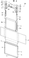
- FIG. 1 is an external perspective view of a flat wound secondary battery
- FIG. 2 is an exploded perspective view of a square secondary battery.
- the flat wound secondary battery 100 includes a battery can 1 and a lid (battery lid) 6.
- the battery can 1 has a side surface and a bottom surface 1d having a pair of opposed wide side surfaces 1b having a relatively large area and a pair of opposed narrow side surfaces 1c having a relatively small area, and an opening 1a above the side surface 1d.
- the wound group 3 is accommodated in the battery can 1, and the opening 1 a of the battery can 1 is sealed by the battery lid 6.
- the battery lid 6 has a substantially rectangular flat plate shape, and is welded so as to close the upper opening 1 a of the battery can 1 to seal the battery can 1.
- the battery lid 6 is provided with a positive external terminal 14 and a negative external terminal 12.
- the wound group 3 is charged through the positive external terminal 14 and the negative external terminal 12, and power is supplied to the external load.
- the battery cover 6 is integrally provided with a gas discharge valve 10. When the pressure in the battery container increases, the gas discharge valve 10 is opened to discharge gas from the inside, and the pressure in the battery container is reduced. Therefore, the safety of the flat wound secondary battery 100 is ensured.
- a wound group 3 is accommodated in the battery can 1 via an insulating protective film 2.
- the wound group 3 is wound into a flat shape, and has a pair of curved surface portions facing each other and having a semicircular cross section, and a flat surface portion formed continuously between the pair of curved surface portions. Yes.
- the winding group 3 is inserted into the battery can 1 from one curved surface portion side so that the winding axis direction is along the lateral width direction of the battery can 1, and the other curved surface portion side is arranged on the opening 1a side. .
- the positive electrode foil exposed portion 34 c of the winding group 3 is electrically connected to the positive external terminal 14 provided on the battery lid 6 via a positive current collector plate (current collector terminal) 44.
- the negative electrode foil exposed portion 32 c of the wound group 3 is electrically connected to the negative external terminal 12 provided on the battery lid 6 via a negative current collector (current collector terminal) 24.
- a gasket 5 and an insulating plate 7 are provided on the battery lid 6. It has been. Moreover, after injecting electrolyte solution into the battery can 1 from the injection hole 9, the injection stopper 11 is joined to the battery cover 6 by laser welding to seal the injection hole 9, and the flat wound secondary battery 100 is sealed.
- the forming material of the positive electrode external terminal 14 and the positive electrode current collector plate 44 includes, for example, an aluminum alloy
- the forming material of the negative electrode external terminal 12 and the negative electrode current collector plate 24 includes, for example, a copper alloy.
- the material for forming the insulating plate 7 and the gasket 5 include resin materials having insulating properties such as polybutylene terephthalate, polyphenylene sulfide, and perfluoroalkoxy fluororesin.
- the battery lid 6 is provided with a liquid injection port 9 for injecting an electrolytic solution into the battery container.
- the liquid injection port 9 is an injection stopper after the electrolytic solution is injected into the battery container. 11 is sealed.
- a non-aqueous electrolytic solution in which a lithium salt such as lithium hexafluorophosphate (LiPF 6 ) is dissolved in a carbonic acid ester-based organic solvent such as ethylene carbonate is used. Can be applied.
- the positive external terminal 14 and the negative external terminal 12 have a weld joint that is welded to a bus bar or the like.
- the weld joint has a rectangular parallelepiped block shape protruding upward from the battery lid 6, and has a configuration in which the lower surface faces the surface of the battery lid 6 and the upper surface is parallel to the battery lid 6 at a predetermined height position. Have.
- the positive electrode connecting portion 14a and the negative electrode connecting portion 12a have a cylindrical shape that protrudes from the lower surfaces of the positive electrode external terminal 14 and the negative electrode external terminal 12 and can be inserted into the positive electrode side through hole 46 and the negative electrode side through hole 26 of the battery lid 6.
- the positive electrode connection portion 14 a and the negative electrode connection portion 12 a penetrate the battery lid 6 and are more inside the battery can 1 than the positive electrode current collector plate 44, the positive electrode current collector plate base 41 of the negative electrode current collector plate 24, and the negative electrode current collector plate base 21.
- the positive electrode external terminal 14, the negative electrode external terminal 12, the positive electrode current collector plate 44, and the negative electrode current collector plate 24 are integrally fixed to the battery lid 6.
- a gasket 5 is interposed between the positive electrode external terminal 14 and the negative electrode external terminal 12 and the battery cover 6, and an insulating plate is interposed between the positive electrode current collector plate 44, the negative electrode current collector plate 24 and the battery cover 6. 7 is interposed.
- the positive electrode current collector plate 44 and the negative electrode current collector plate 24 are a rectangular plate-shaped positive electrode current collector plate base 41, a negative electrode current collector plate base 21, and a positive electrode current collector plate base 41 that are arranged to face the lower surface of the battery lid 6.
- the negative electrode current collector plate base 21 is bent at the side end and extends toward the bottom surface along the wide surface of the battery can 1, and the positive electrode foil exposed portion 34 c of the wound group 3, the negative electrode foil exposed portion It has the positive electrode side connection end part 42 and the negative electrode side connection end part 22 which are connected in the state which overlapped facing 32c.
- the positive electrode current collector plate base 41 and the negative electrode current collector plate base 21 are respectively formed with a positive electrode side opening hole 43 and a negative electrode side opening hole 23 through which the positive electrode connection part 14a and the negative electrode connection part 12a are inserted.
- the insulating protective film 2 is wound around the winding group 3 with the direction along the flat plane of the winding group 3 and the direction orthogonal to the winding axis direction of the winding group 3 as the central axis direction.
- the insulating protective film 2 is made of a single sheet or a plurality of film members made of synthetic resin such as PP (polypropylene), for example, and is a direction parallel to the flat surface of the wound group 3 and perpendicular to the winding axis direction. Has a length that allows one or more turns to be wound.
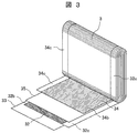
- FIG. 3 is an exploded perspective view showing a state in which a part of the wound electrode group is developed.
- the winding group 3 is configured by winding the negative electrode 32 and the positive electrode 34 with separators 33 and 35 interposed therebetween.
- the outermost electrode is the negative electrode 32, and the separators 33 and 35 are wound further outward.
- the separators 33 and 35 have a role of insulating between the positive electrode 34 and the negative electrode 32.
- the portion where the negative electrode mixture layer 32b of the negative electrode 32 is applied is configured to be larger in the width direction than the portion of the positive electrode 34 where the positive electrode mixture layer 34b is applied, and both end portions of the negative electrode mixture layer 32b are formed.
- the positive electrode mixture layer 34b is always sandwiched between the negative electrode mixture layers by overlapping the positive electrode mixture layers 34b so as to protrude in the width direction from both ends.
- the positive electrode foil exposed portion 34c and the negative electrode foil exposed portion 32c are bundled at a plane portion and connected by welding or the like.
- the separators 33 and 35 are wider than the portion where the negative electrode mixture layer 32b is applied in the width direction, but at positions where the metal foil surface at the end is exposed at the positive electrode foil exposed portion 34c and the negative electrode foil exposed portion 32c. Because it is wound, it does not hinder bundled welding.
- the positive electrode 34 has a positive electrode active material mixture on both sides of a positive electrode foil that is a positive electrode current collector, and a positive electrode that does not apply the positive electrode active material mixture to one end in the width direction of the positive electrode foil A foil exposed portion 34c is provided.
- the negative electrode 32 has a negative electrode active material mixture on both sides of a negative electrode foil that is a negative electrode current collector, and the negative electrode without applying the negative electrode active material mixture to the other end in the width direction of the negative electrode foil A foil exposed portion 32c is provided.
- the positive electrode foil exposed portion 34c and the negative electrode foil exposed portion 32c are regions where the metal surface of the electrode foil is exposed, and are wound so as to be disposed at one side and the other side in the winding axis direction.
- negative electrode 32 10 parts by weight of polyvinylidene fluoride (hereinafter referred to as PVDF) is added as a binder to 100 parts by weight of amorphous carbon powder as a negative electrode active material, and N as a dispersion solvent.
- NMP kneading methylpyrrolidone
- amorphous carbon is used as the negative electrode active material, but the present invention is not limited to this.
- Natural graphite capable of inserting and removing lithium ions and various artificial graphite materials Carbonaceous materials such as coke, compounds such as Si and Sn (for example, SiO, TiSi 2 etc.), or composite materials thereof may be used. It is not limited.
- the positive electrode 34 10 parts by weight of scaly graphite as a conductive material and 10 parts by weight of PVDF as a binder are added to 100 parts by weight of lithium manganate (chemical formula LiMn 2 O 4) as a positive electrode active material, A positive electrode mixture was prepared by adding and kneading NMP as a dispersion solvent thereto. This positive electrode mixture was applied to both surfaces of an aluminum foil (positive electrode foil) having a thickness of 20 ⁇ m, leaving the welded portion (positive electrode uncoated portion). Thereafter, a positive electrode 31 having a thickness of 90 ⁇ m in the thickness of the positive electrode active material application part not including an aluminum foil was obtained through drying, pressing, and cutting processes.
- NMP lithium manganate
- lithium manganate is used as the positive electrode active material
- other lithium manganate having a spinel crystal structure or a lithium manganese composite oxide or layered in which a part is substituted or doped with a metal element A lithium cobalt oxide or lithium titanate having a crystal structure, or a lithium-metal composite oxide obtained by substituting or doping a part thereof with a metal element may be used.
- polytetrafluoroethylene PTFE
- polyethylene polystyrene
- polybutadiene butyl rubber
- nitrile rubber styrene
- Use polymers such as butadiene rubber, polysulfide rubber, nitrocellulose, cyanoethyl cellulose, various latexes, acrylonitrile, vinyl fluoride, vinylidene fluoride, propylene fluoride, chloroprene fluoride, acrylic resins, and mixtures thereof.
- the wound group 3 has an axis 80 (see FIG. 5) at the center thereof.
- the shaft core 80 is configured by bending a resin sheet member 81 having higher bending rigidity than any of the positive electrode foil 31a, the negative electrode foil 32a, and the separator 33. The detailed configuration of the shaft core 80 will be described later.
- FIG. 4 is a diagram showing a configuration example of the winding machine.
- the winding machine 200 has a spindle 101 rotatably supported at the center of the device, and is driven to rotate clockwise by a rotation driving device (not shown).
- a supply device for supplying the sheet member 81, the negative electrode 32, the separator 33 (first separator), the positive electrode 34, and the separator 35 (second separator) to the spindle 101 is provided on the side of the spindle 101. Is provided.
- the supply device holds the sheet member 81, the negative electrode 32, the separator 33, the positive electrode 34, and the separator 35 in order from the upper right side of the device in a roll shape, and is fed out from the outer peripheral end portion and supplied to the spindle 101. Yes. Further, feed rollers 160a to 160e for supplying the electrodes 32 and 34, separators 33 and 35, and the sheet member 81 to predetermined positions, and cutters 161a to 161d for cutting at predetermined lengths are provided. Note that a cutter for cutting the sheet member 81 is not shown.
- a flat winding core 102 is attached to the spindle 101, and a provisional pressing mechanism 178 is provided for holding the sheet member 81 wound around the winding core 102 so that the sheet member 81 is not unraveled when being cut.
- an attaching means 167 for attaching the adhesive tape 163 so that the wound group 3 cannot be unwound.
- the pasting means 167 is a part surrounded by a broken line in the figure, and has a delivery mechanism 164, a cutter 165, and a pasting mechanism 168.
- the adhesive tape 163 is fed by a predetermined length by the feed mechanism 164, cut to a predetermined length by the cutter 165, and is stuck to the wound group 3 by the sticking mechanism 168.
- a heater head 170 for heating and welding the separators 33 and 35 to the sheet member 81 as necessary, and a heater moving mechanism 171 for moving and heating the heater head 170 to a predetermined position are provided in the vicinity of the spindle 101.
- a heater head 170 for heating and welding the separators 33 and 35 to the sheet member 81 as necessary, and a heater moving mechanism 171 for moving and heating the heater head 170 to a predetermined position are provided in the vicinity of the spindle 101.
- bonding may be performed using an adhesive tape. Therefore, in this case, although not shown, a mechanism similar to the attaching means 167 for attaching a tape is provided separately from the heater head 107 and the heater moving mechanism 171.
- the sheet member 81 and the separators 33 and 35 are held by the winding core 102. Then, the sheet member 81 and the separators 33 and 35 are wound together by the rotation of the winding core 102.
- the sheet member 81 is in direct contact with the winding core 102, and the separator 33 is in direct contact with the sheet member 81.
- the sheet member 81 and the separators 33 and 35 are directly held on the winding core 102. Then, the winding core 102 is rotated to wind the sheet member 81 and the separators 33 and 35 together.
- the sheet member 81 is wound around the winding core 102 by the separators 33 and 35, is bent in a flat shape along the shape of the winding core 102, and the separators 33 and 35 are wound around the sheet member 81.
- the negative electrode 32 is inserted and sandwiched between the wound body in which the separators 33 and 35 are wound around the sheet member 81 one or more times and the separator 33 wound further outside, and the negative electrode 32
- the positive electrode 34 is inserted and sandwiched between the separator 33 and the outer separator 35, and the winding core 102 is rotated a predetermined number of times.
- the end portion of the negative electrode 32 is made longer than the end portion of the positive electrode 34 by one or more turns, and the outer periphery of the positive electrode 34 is covered with the outermost negative electrode 32.
- the outer periphery of the outermost negative electrode 32 is covered with separators 33 and 35, and the end portions of the separators 33 and 35 are fixed by sticking an adhesive tape 163 by a sticking means 167 so that the wound group 3 is not unwound.
- the wound group 3 is removed by being extracted from the winding core 102 and pressed in the thickness direction to obtain a final shape (see FIG. 3).
- Example 1 Next, Example 1 in the present embodiment will be described.
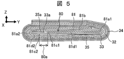
- FIG. 5 is a diagram illustrating the configuration of the winding center portion of the winding group in the first embodiment
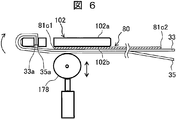
- FIGS. 6 and 7 are diagrams illustrating the winding method of the shaft core and the separator in the first embodiment.
- the wound group 3 is wound in a flat shape by the winding machine 200, then extracted from the winding core 102, pressed in the flat thickness direction, and formed into a final shape.
- the winding group 3 has a semi-circular curved surface portion formed at both ends of the flat surface portion in the winding direction, and has a substantially track-shaped cross section (see FIG. 3).
- the sheet member 81 that forms the shaft core 80 is disposed at the center of the winding group 3, and in a state before the winding group 3 is pressed, end portions on both sides in the winding direction of the sheet member 81 are mutually connected. Each is bent in the approaching direction (see FIG. 7). And in the state of the final shape by which the winding group 3 was pressed, as shown in FIG. 5, it is crushed by the press in the thickness direction, and becomes flat plate shape. As shown in FIG. 7, the sheet member 81 has a length of less than one turn when wound around the winding core 102.
- the shaft core 80 is configured such that the front end portions 81c1 and 81c2 on both sides in the winding direction of the sheet member 81 are folded back in a direction approaching each other, and the front end portions are arranged at positions spaced apart from each other with a predetermined gap 80a. Have.
- a planar substrate portion 81b that extends along the winding direction, and a pair of bends that are folded back toward each other on one side and the other side of the substrate portion 81b in the winding direction.
- Parts 81a1 and 81a2 and a pair of folded piece parts 81d1 and 81d2 extending from the pair of bent parts 81a1 and 81a2 along the substrate part 81b toward each other.
- the winding start ends of the separators 33 and 35 are held on the one surface 102 a side of the winding core 102. Then, the winding core 102 is rotated while being pressed by the temporary holding mechanism 178, and the separators 33 and 35 are wound around one end in the winding direction of the winding core 102, and the other surface 102 b of the winding core 102 and the separator 33 are wound around the winding core 102.
- the winding start end side of the sheet member 81 is sandwiched therebetween.
- the core 102 is further rotated, and the separators 33 and 35 are wound around the core 102 one or more times as shown in FIG.
- the sheet member 81 is bent along the core 102 and wound less than one turn, the substrate portion 81b is disposed on the one surface 102a side of the core 102, and the other surface 102b side of the core 102 is disposed.
- the tip portions 81c1 and 81c2 are disposed.
- the pressing by the temporary pressing mechanism 178 is released to rotate the winding core 102, and the winding start end portion of the negative electrode 32 is first placed between the separator 35 and the outer separator 33 on the one surface 102 a side of the winding core 102. Then, the winding start end portion of the positive electrode 34 is inserted between the separator 33 and the outer separator 35 at a slightly delayed timing. And the winding group 3 which has the positive electrode 34 and the negative electrode 32 of predetermined length is formed by rotating the winding core 102 only predetermined times.
- the winding group 3 is removed from the winding core 102 after the outermost separator 35 is fixed to the outer peripheral surface with the adhesive tape, and then the holding of the separators 33 and 35 by the winding core 102 is released. Then, it is pressed with a predetermined pressing force in the thickness direction to form a final shape (see FIG. 5).
- the manufacturing process can be simplified with a simple structure.
- the conventional operation of inserting a cylindrical shaft core in advance into the spindle of the winding machine 200 can be omitted, and productivity can be improved by automation.
- it is not necessary to prepare a cylindrical shaft in advance the cost can be reduced by that amount, and this is suitable for mass production.
- the wound group 3 has a flat shaft core 80 that is crushed in the flat thickness direction (Z direction in FIG. 5) by pressing.
- the shaft core 80 has a pair of bent portions 81a1 and 81a2 that are separated in the winding direction (Y direction in FIG. 5) and extend in the winding axis direction (X axis direction in FIG. 5). Therefore, the length in the winding direction (Y direction) of the shaft core 80 can always be defined to be constant, and errors between products can be eliminated.
- the separators 33 and 35, the negative electrode 32, and the positive electrode 34 are prevented from being bent at an angle, and these are smoothly bent so that the cross section is a semicircular arc. be able to.
- the shaft core 80 has one folded piece portion 81d1 having a tip portion 81c1 and the substrate portion 81b directly facing each other, and the other folded piece portion 81d2 having the tip portion 81c2 and the substrate portion. Between 81b, the winding start end portions 33a and 35a of the two separators 33 and 35 are folded back and folded in half.
- the radius of the innermost peripheral surface is a value obtained by adding the thickness of four separators and the thickness of one sheet member 81, and is equal to each other. Therefore, it is possible to prevent the minimum radius of any one of the curved portions of the negative electrode 32 from being minimized, and to reduce the force in the peeling direction that acts on the negative electrode mixture of the curved portion. Accordingly, the pressure for pressing the negative electrode mixture layer 32b of the negative electrode 32 can be increased to increase the density of the negative electrode mixture layer 32b, and the performance of the battery can be improved.
- separators 33 and 35 are necessarily interposed between the shaft core 80 and the negative electrode 32. Therefore, the electrolyte can be sufficiently supplied also to the innermost negative electrode 32 through the separators 33 and 35, and the reactivity of the battery can be improved.
- the gap 80a of the shaft core 80 described above is formed in the center portion of the winding group 3 in the winding axis direction. Therefore, the electrolytic solution can be circulated through the gap 80 a and supplied to the central portion of the wound group 3, and the electrolytic solution can be supplied uniformly over the entire wound group 3. Therefore, the performance of the battery can be improved by improving the reactivity inside the battery.
- the negative electrode 32 is wound, and the separators 33 and 35 are wound over the entire outer periphery of the shaft core 80.
- the shaft core 80 is formed by bending a resin sheet member 81 having higher bending rigidity than any of the positive electrode foil 31a, the negative electrode foil 32a, and the separator 33, the pair of bent portions 81a1 and 81a2 are formed.
- the spring back can generate a stress that urges the substrate group 81b and the folded piece portions 81d1 and 81d2 in the direction of expanding at the center position of the wound group 3. Therefore, loosening of the winding group 3 can be prevented, and vibration resistance and impact resistance can be secured.
- Example 2 Next, Example 2 in the present embodiment will be described.
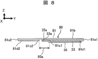
- FIG. 8 is a diagram illustrating the configuration of the winding center portion of the winding group in the second embodiment
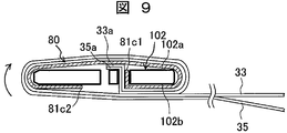
- FIG. 9 is a diagram illustrating the winding method of the sheet member and the separator in the second embodiment.
- the same components as those in the first embodiment are denoted by the same reference numerals, and detailed description thereof is omitted.
- the winding start ends of the separators 33 and 35 are arranged in the gap 80a.
- one folded piece portion 81d1 and the substrate portion 81b are directly opposed to each other, and the other folded piece portion 81d2 and the substrate portion 81b are directly opposed to each other.
- the winding start end portions of the separators 33 and 35 are disposed in the gap 80 a, and the separators 33 and 35 are wound around the shaft core 80.
- the winding start end portion 81 c 1 of the sheet member 81 and the separators 33 and 35 are overlapped and inserted into the slit from the other surface 102 b side of the winding core 102 and held on the winding core 102.
- the winding start end portions 33a and 35a of the separators 33 and 35 are longer than the winding start end portion 81c1 of the sheet member 81 by the length that fits in the gap 80a, and protrude toward the one surface 102a side of the winding core 102.
- the sheet member 81 has a length that is less than one turn when wound around the core 102.
- the winding core 102 is rotated, and the separators 33 and 35 are wound around the winding core 102 one or more times.
- the sheet member 81 is bent along the core 102 and wound less than one turn, the substrate portion 81b is disposed on the one surface 102a side of the core 102, and the other surface 102b side of the core 102 is disposed.
- the tip portions 81c1 and 81c2 are disposed.
- the winding core 102 is further rotated, and in the same manner as in the first embodiment, a wound body in which the separators 33 and 35 are wound around the sheet member 81 by one turn or more, and a separator 33 wound further outward.
- the negative electrode 32 is inserted and sandwiched between them, and at a timing later than the insertion of the negative electrode 32, the positive electrode 34 is inserted and sandwiched between the separator 33 and the outer separator 35 so that the winding core 102 is fixed
- the wound group 3 is formed by rotating it a number of times.
- the wound group 3 is removed from the winding core 102 and then pressed in the thickness direction with a predetermined pressing force to form a final shape.
- the winding group 3 can be manufactured simply by holding the resin sheet 81 and the separators 33 and 35 with the winding core 102 and winding, thereby simplifying the manufacturing process with a simple structure. it can.
- the winding group 3 is wound around the winding core 102 in a state where the winding start end portions 33a and 35a of the separators 33 and 35 protrude from the one end portion 81c1 of the sheet member 81. . Therefore, the winding start end portions 33a and 35a of the separators 33 and 35 wound around the outer peripheral side protrude toward the gap 80a side from the leading end portion 81c1 of the sheet member 81 wound around the inner peripheral side, and the gap 80a Is housed in. Therefore, the gap 80a can be partially filled with the winding start ends 33a and 35a of the separators 33 and 35, and the height of the step formed by the gap 80a can be reduced.
- the separators 33 and 35 are wound around at least a part of the outer periphery of the shaft core 80 formed of the sheet member 81. Therefore, the separators 33 and 35 are also arranged on the inner peripheral side of the innermost negative electrode 32, and the electrolyte solution can be held by the separators 33 and 35. Therefore, the electrolytic solution can be supplied uniformly over the entire wound group 3, and the reactivity of the battery can be improved.
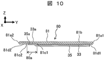
- FIG. 10 and FIG. 11 are diagrams showing modifications of the wound group in the present embodiment.
- What is characteristic in the modification shown in FIG. 10 is that the position of the gap 80a is biased to a position that becomes the upstream side (left side in the figure) during winding compared to the configuration example shown in FIG. is there.
- the winding group 3 is wound by rotating clockwise in the state shown in FIG.
- One folded piece 81d1 that is upstream when wound is longer than the other folded piece 81d2 that is downstream when wound, and the tip 81c2 is disposed at a position close to the other bent portion 81a2. Yes. Therefore, when the separators 33 and 35 are started to be rolled, the area of the contact surface where the separator 33 contacts the folded piece portion 81d1 can be increased.
- the separators 33 and 35 when winding the separators 33 and 35 around the bent portion 81a1 of the shaft core 80, the separators 33 and 35 having rigidity lower than that of the sheet member 81 are pulled more than necessary due to the back tension of the winding machine 200. Can be prevented.
- the gap 80a is arranged at a position biased to the downstream side (right side in the drawing) at the time of winding, so that the length of the separators 33 and 35 to be pulled is shortened, and the length of the affected separator is reduced. You can also. Also in this configuration example, since the sheet member 81 and the separators 33 and 35 are only held and wound by the winding core 102, the manufacturing process can be simplified with a simple structure.
- the size of the gap 80a is increased as compared with the configuration example shown in FIG.
- the entire length of the resin sheet 181 can be shortened, so that the material cost can be saved and the cost can be reduced.
- the gap 80a is biased to the downstream side (right side in the drawing) during winding, the lengths of the separators 33 and 5 to be pulled are shortened, and the lengths of the affected separators 33 and 35 are reduced.
- the thickness can also be reduced.
- Example 3 Next, Example 3 in the present embodiment will be described.
- FIG. 12 is a diagram illustrating the configuration of the winding center portion of the winding group in the third embodiment
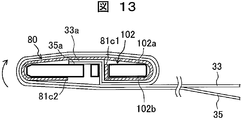
- FIG. 13 is a diagram illustrating the winding method of the sheet member and the separator in the third embodiment. Note that the same components as those in the above-described embodiments are denoted by the same reference numerals, and detailed description thereof is omitted.
- the winding group 3 in the present embodiment has a configuration in which the winding start end portions of the separators 33 and 35 are sandwiched between the substrate portion 81b and the folded piece portion 81d2 through the gap 80a of the shaft core 80.
- the winding start end portions 33 a and 35 a of the separators 33 and 35 and the sheet member 81 are slit from the other surface 102 b side of the winding core 102 to the slit.
- Each tip 81c1 is inserted and held.
- the leading ends of the separators 33 and 35 are protruded by a predetermined length toward the one surface 102 a of the winding core 102.
- the winding core 102 is rotated, and the separators 33 and 35 are wound around the winding core 102 one or more times.
- the sheet member 81 is bent along the core 102 and wound less than one turn, the substrate portion 81b is disposed on the one surface 102a side of the core 102, and the other surface 102b side of the core 102 is disposed.
- the tip portions 81c1 and 81c2 are disposed.
- the negative electrode 32 and the positive electrode 34 are wound while the winding core 102 is rotated to form the wound group 3, removed from the winding machine 200, pressed in the thickness direction, and formed into a final shape.
- the shaft core 80 has a flat plate shape that is crushed in the thickness direction by a press.
- One folded piece portion 81d1 and the substrate portion 81b face each other, and the other folded piece portion 81d2 and the substrate portion 81b are formed.
- the separators 33 and 35 protrude from the front end portion 81c1 of the sheet member 81 and pass through the gap 80a, and the winding start end portions 33a and 35a are sandwiched between the other folded piece portion 81d2 of the shaft core 80 and the substrate portion 81b. It is.
- the present embodiment is configured in that the winding start end portions 33a and 35a of the separators 33 and 35 are not folded in half between the folded piece portion 81d2 and the substrate portion 81b. Is different.
- the separators 33 and 35 pass through the gap 80a and overlap the one folded piece portion 81d1.
- the winding start end portions 33a and 35a of the separators 33 and 35 are sandwiched between the folded piece portion 81d2 and the substrate portion 81b, and can be prevented from moving as free ends. .
- the holding process is only once, and the manufacturing process can be performed with a simple structure. It can be simplified.
- the sheet member 81 may be sandwiched and fixed between the separators 33 and 35 and the core 102 that are wound around the core 102 and wound. Also in the present embodiment, as described above, the position and width of the gap 80a are not limited to the example of FIG. 12, but can be freely changed as shown in FIG. 10 and FIG.
- Example 4 Next, Example 4 in the present embodiment will be described.
- FIG. 14 is a diagram illustrating the configuration of the winding center portion of the winding group in the fourth embodiment
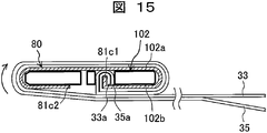
- FIG. 15 is a diagram illustrating the winding method of the sheet member and the separator in the fourth embodiment. Note that the same components as those in the above-described embodiments are denoted by the same reference numerals, and detailed description thereof is omitted.
- the winding group 3 in the present embodiment has a configuration in which the winding start end portions of the separators 33 and 35 are sandwiched between the substrate portion 81b and the one folded piece portion 81d1 through the gap 80a of the shaft core 80. Yes.
- the winding start end portions 33a and 35a of the separators 33 and 35 are folded back, and the leading end portion 81c1 of the sheet member 81 is sandwiched therebetween. In this state, it is inserted into the slit of the winding core 102 and held. Then, the winding core 102 is rotated, and the separators 33 and 35 are wound around the winding core 102 one or more times.
- the sheet member 81 is bent along the core 102 and wound less than one turn, the substrate portion 81b is disposed on the one surface 102a side of the core 102, and the other surface 102b side of the core 102 is disposed.
- the tip portions 81c1 and 81c2 are disposed.
- the negative electrode 32 and the positive electrode 34 are wound while the winding core 102 is rotated to form the wound group 3, removed from the winding machine 200, pressed in the thickness direction, and formed into a final shape.
- the shaft core 80 has a flat plate shape that is crushed in the thickness direction by a press.
- One folded piece portion 81d1 and the substrate portion 81b face each other, and the other folded piece portion 81d2 and the substrate portion 81b are formed.
- the separators 33 and 35 are bent so as to pass through the gap 80a and sandwich the leading end portion 81c1 of the sheet member 81, and the winding start end portions 33a and 35a are one folded piece portion 81d1 of the shaft core 80 and the substrate portion 81b. It is sandwiched between.
- the winding start end portions 33a and 35a of the separators 33 and 35 are sandwiched between the folded piece portion 81d1 and the substrate portion 81b, and can be prevented from moving as free ends. .
- the holding process is only once, and the manufacturing process can be performed with a simple structure. It can be simplified. Also in the present embodiment, as described above, the position and width of the gap 80a are not limited to the example of FIG. 14, but can be freely changed as shown in FIGS.
- Example 5 Next, Example 5 in the present embodiment will be described.
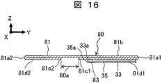
- FIG. 16 is a diagram illustrating the configuration of the winding center portion of the winding group in the fifth embodiment
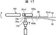
- FIGS. 17 and 18 are diagrams illustrating the winding method of the sheet member and the separator in the fifth embodiment. Note that the same components as those in the above-described embodiments are denoted by the same reference numerals, and detailed description thereof is omitted.
- the winding group 3 in the present embodiment has a configuration in which the winding start end portions of the separators 33 and 35 are welded to the shaft core 80.
- the leading end portion 81 c 1 of the sheet member 81 is inserted and held in the slit from the other surface 102 b side of the winding core 102.
- the winding start end portions 33a and 35a of the separators 33 and 35 are heat-welded and fixed to the sheet member 81.
- the heat welding is performed by superimposing the winding start end portions 33a and 35a of the separators 33 and 35 on one folded piece portion 81d1 of the sheet member 81 and pressing the heated heater head 170, whereby the sheet member 81 and the separator 33 are pressed.
- 35 is formed between the winding start end portions 33a and 35a.
- the winding core 102 is rotated, and the separators 33 and 35 are wound around the winding core 102 one or more times.
- the sheet member 81 is bent along the core 102 and wound less than one turn, the substrate portion 81b is disposed on the one surface 102a side of the core 102, and the other surface 102b side of the core 102 is disposed.
- the tip portions 81c1 and 81c2 are disposed.
- the negative electrode 32 and the positive electrode 34 are wound while the winding core 102 is rotated to form the wound group 3, removed from the winding machine 200, pressed in the thickness direction, and formed into a final shape.
- the step of holding the winding start end portions 33a, 35a of the separators 33, 35 by the winding core 102 of the winding machine 200 can be omitted, and the manufacturing process can be simplified with a simple structure.
- the winding start end portions 33a and 35a of the separators 33 and 35 are fixed to the sheet member 81 by heat welding, the adhesion between the separators 33 and 35 and the sheet member 81 is improved. In this way, defects such as separation of the separators 33 and 35 are prevented.
- the gap 80a is larger than the leading end portion 81c1 of the sheet member 81 wound on the inner peripheral side. There is no need to protrude to the side. Also in the present embodiment, as described above, the position and the width of the gap 80a are not limited to the example of FIG. 16, but can be freely changed as shown in FIGS.
- Example 6 Next, Example 6 in the present embodiment will be described.
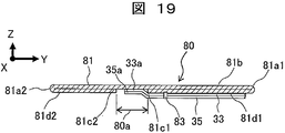
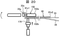
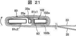
- FIG. 19 is a diagram for explaining the configuration of the winding center portion of the winding group in Example 6, and FIGS. 20 and 21 are diagrams for explaining the winding method of the sheet member and the separator in Example 6.
- the winding group 3 in the present embodiment has a configuration in which the separators 33 and 35 are welded to the shaft core 80 and the winding start end portions 33a and 35a are disposed in the gap 80a.
- the winding start end portion 81c1 of the sheet member 81 and the separators 33, 35 are used.
- the winding start end portions 33 a and 35 a are overlapped and held on the winding core 102.
- the winding start end portions 33a and 35a of the separators 33 and 35 are longer than the winding start end portion 81c1 of the sheet member 81 by the length that fits in the gap 80a, and protrude toward the one surface 102a side of the winding core 102.
- the sheet member 81 has a length that is less than one turn when wound around the core 102.
- the sheet member 81 and the separators 33 and 35 that are overlapped with each other on the other surface 102b side of the winding core 102 are heat-welded and fixed to each other.
- the heat welding is performed by pressing the heater head 170 in the thickness direction from the outside of the separators 33 and 35, and a welding portion 83 is formed between the sheet member 81 and the winding start end portions 33a and 35a of the separators 33 and 35. Is done.
- the winding core 102 is rotated, and the separators 33 and 35 are wound around the winding core 102 one or more times as shown in FIG.
- the sheet member 81 is bent along the core 102 and wound less than one turn, the substrate portion 81b is disposed on the one surface 102a side of the core 102, and the other surface 102b side of the core 102 is disposed.
- the tip portions 81c1 and 81c2 are disposed.
- the negative electrode 32 and the positive electrode 34 are wound while the winding core 102 is rotated to form the wound group 3, which is removed from the winding machine 200 and pressed in the thickness direction to obtain the final shape described above. Molded.
- the winding start end portions 33a and 35a of the separators 33 and 35 are fixed to the sheet member 81 by heat welding, the adhesion between the separators 33 and 35 and the sheet member 81 is improved. Defects such as separation of the separators 33 and 35 can be prevented. Also in the present embodiment, as described above, the position and width of the gap 80a are not limited to the example of FIG. 19, but can be freely changed as shown in FIGS.
- the position of the welded portion 83 may be set not in the front end portion 81c1 side of the sheet member 81 but in the vicinity of the bent portion 81a1 on the right side in the drawing. In this case, the length of the separator pulled as described above is shortened, and the length of the affected separator can be reduced.
- the present invention is not limited to the above-described embodiments, and various designs can be made without departing from the spirit of the present invention described in the claims. It can be changed.
- the above-described embodiment has been described in detail for easy understanding of the present invention, and is not necessarily limited to one having all the configurations described.
- a part of the configuration of an embodiment can be replaced with the configuration of another embodiment, and the configuration of another embodiment can be added to the configuration of an embodiment.
Landscapes
- Engineering & Computer Science (AREA)
- Chemical & Material Sciences (AREA)
- Manufacturing & Machinery (AREA)
- Chemical Kinetics & Catalysis (AREA)
- Electrochemistry (AREA)
- General Chemical & Material Sciences (AREA)
- Materials Engineering (AREA)
- Secondary Cells (AREA)
Abstract
Description
捲回群3は、その中心に軸芯80(図5を参照)を有している。
次に、本実施の形態における実施例1について説明する。
次に、本実施の形態における実施例2について説明する。
次に、本実施の形態における実施例3について説明する。
次に、本実施の形態における実施例4について説明する。
次に、本実施の形態における実施例5について説明する。
次に、本実施の形態における実施例6について説明する。
3 捲回群
6 電池蓋
32 負極電極
33、35 セパレータ
33a、35a 巻き始め端部
34 正極電極
80 軸芯
80a 隙間
81 シート部材
81a1、81a2 屈曲部
81b 基板部
81c1、81c2 先端部
81d1、81d2 折り返し片部
83 溶着部
100 扁平捲回形二次電池
Claims (9)
- 正極電極及び負極電極を間にセパレータを介して捲回した扁平状の捲回群を有する扁平捲回形二次電池であって、
前記捲回群は、前記正極電極と前記負極電極と前記セパレータのいずれよりも曲げ剛性の高いシート部材の捲回方向両側の先端部が互いに接近する方向にそれぞれ折り返されて先端部どうしが離間した位置に配置された構成の軸芯を有することを特徴とする扁平捲回形二次電池。 - 前記軸芯は、
捲回方向に沿って広がる平面状の基板部と、
該基板部の捲回方向一方側と他方側で互いに接近する方向に折り返される一対の屈曲部と、
該一対の屈曲部から前記基板部に沿って互いに接近する方向に延出して前記先端部をそれぞれ有する一対の折り返し片部と、を有することを特徴とする請求項1に記載の扁平捲回形二次電池。 - 前記軸芯と前記負極電極との間に前記セパレータが介在されていることを特徴とする請求項2に記載の扁平捲回形二次電池。
- 前記セパレータは、前記軸芯の外周全周に亘って当接して捲回されていることを特徴とする請求項3に記載の扁平捲回形二次電池。
- 前記セパレータの捲き始め端部が前記軸芯の互いに離間する先端部の間の隙間に配置されていることを特徴とする請求項3または4に記載の扁平捲回形二次電池。
- 前記セパレータの捲き始め端部が前記一対の折り返し片部の一方と前記基板部との間に挟まれていることを特徴とする請求項3または4に記載の扁平捲回形二次電池。
- 前記セパレータは、該セパレータの巻き始め端部が二つ折りに折り曲げられて前記一対の折り返し片部の一方と前記基板部との間に挟まれており、前記軸芯の互いに対向する先端部の間の隙間を通過して、前記一対の折り返し片部の他方に重ね合わされて捲回されていることを特徴とする請求項3または4に記載の扁平捲回形二次電池。
- 前記セパレータは、該セパレータの巻き始め端部が前記一対の折り返し片部の一方と前記基板部との間に挟まれており、該一方の折り返し片部が有する前記先端部を間に介在させて折り返されていることを特徴とする請求項3または4に記載の扁平捲回形二次電池。
- 前記セパレータは、前記軸芯に溶着されていることを特徴とする請求項1に記載の扁平捲回形二次電池。
Priority Applications (4)
| Application Number | Priority Date | Filing Date | Title |
|---|---|---|---|
| CN201380077866.6A CN105340122B (zh) | 2013-06-28 | 2013-06-28 | 扁平卷绕式二次电池 |
| US14/898,484 US20160118682A1 (en) | 2013-06-28 | 2013-06-28 | Flat-winding type secondary battery |
| JP2015523768A JP6104383B2 (ja) | 2013-06-28 | 2013-06-28 | 扁平捲回形二次電池 |
| PCT/JP2013/067768 WO2014207883A1 (ja) | 2013-06-28 | 2013-06-28 | 扁平捲回形二次電池 |
Applications Claiming Priority (1)
| Application Number | Priority Date | Filing Date | Title |
|---|---|---|---|
| PCT/JP2013/067768 WO2014207883A1 (ja) | 2013-06-28 | 2013-06-28 | 扁平捲回形二次電池 |
Publications (1)
| Publication Number | Publication Date |
|---|---|
| WO2014207883A1 true WO2014207883A1 (ja) | 2014-12-31 |
Family
ID=52141282
Family Applications (1)
| Application Number | Title | Priority Date | Filing Date |
|---|---|---|---|
| PCT/JP2013/067768 Ceased WO2014207883A1 (ja) | 2013-06-28 | 2013-06-28 | 扁平捲回形二次電池 |
Country Status (4)
| Country | Link |
|---|---|
| US (1) | US20160118682A1 (ja) |
| JP (1) | JP6104383B2 (ja) |
| CN (1) | CN105340122B (ja) |
| WO (1) | WO2014207883A1 (ja) |
Cited By (1)
| Publication number | Priority date | Publication date | Assignee | Title |
|---|---|---|---|---|
| JP2020177861A (ja) * | 2019-04-22 | 2020-10-29 | トヨタ自動車株式会社 | 電池の製造方法および電池 |
Families Citing this family (5)
| Publication number | Priority date | Publication date | Assignee | Title |
|---|---|---|---|---|
| JP6870591B2 (ja) * | 2017-11-24 | 2021-05-12 | トヨタ自動車株式会社 | 捲回電極体の製造方法 |
| CN110265726A (zh) * | 2019-05-16 | 2019-09-20 | 东莞市爱康电子科技有限公司 | 一种翻折贴胶机构 |
| CN113540706A (zh) * | 2021-07-12 | 2021-10-22 | 欣旺达电动汽车电池有限公司 | 电芯以及电池 |
| JP7389780B2 (ja) * | 2021-10-22 | 2023-11-30 | プライムプラネットエナジー&ソリューションズ株式会社 | 二次電池 |
| CN115513402B (zh) * | 2022-10-28 | 2023-12-29 | 厦门海辰储能科技股份有限公司 | 电极组件、单体电池、电池模组及电极组件的制备方法 |
Citations (6)
| Publication number | Priority date | Publication date | Assignee | Title |
|---|---|---|---|---|
| JPH06187959A (ja) * | 1992-12-21 | 1994-07-08 | Toshiba Battery Co Ltd | 非水電解液電池 |
| JP2000040501A (ja) * | 1998-07-21 | 2000-02-08 | Denso Corp | 扁平巻回電極電池 |
| JP2000138076A (ja) * | 1998-10-30 | 2000-05-16 | Sony Corp | リチウムイオンポリマ二次電池及びその製造装置並びに製造方法 |
| JP2005116186A (ja) * | 2003-10-02 | 2005-04-28 | Toshiba Corp | 非水電解質二次電池 |
| WO2010087384A1 (ja) * | 2009-01-29 | 2010-08-05 | 株式会社Gsユアサ | 電池及び電池の製造方法と、電池における巻芯の製造方法及び巻芯製造装置並びに巻芯 |
| WO2011148866A1 (ja) * | 2010-05-26 | 2011-12-01 | 株式会社Gsユアサ | 電池 |
Family Cites Families (2)
| Publication number | Priority date | Publication date | Assignee | Title |
|---|---|---|---|---|
| CN202503079U (zh) * | 2012-02-07 | 2012-10-24 | 宁德新能源科技有限公司 | 锂离子电池电芯 |
| CN202495548U (zh) * | 2012-02-13 | 2012-10-17 | 东莞新能源科技有限公司 | 一种软包装锂离子电池 |
-
2013
- 2013-06-28 US US14/898,484 patent/US20160118682A1/en not_active Abandoned
- 2013-06-28 CN CN201380077866.6A patent/CN105340122B/zh not_active Expired - Fee Related
- 2013-06-28 JP JP2015523768A patent/JP6104383B2/ja not_active Expired - Fee Related
- 2013-06-28 WO PCT/JP2013/067768 patent/WO2014207883A1/ja not_active Ceased
Patent Citations (6)
| Publication number | Priority date | Publication date | Assignee | Title |
|---|---|---|---|---|
| JPH06187959A (ja) * | 1992-12-21 | 1994-07-08 | Toshiba Battery Co Ltd | 非水電解液電池 |
| JP2000040501A (ja) * | 1998-07-21 | 2000-02-08 | Denso Corp | 扁平巻回電極電池 |
| JP2000138076A (ja) * | 1998-10-30 | 2000-05-16 | Sony Corp | リチウムイオンポリマ二次電池及びその製造装置並びに製造方法 |
| JP2005116186A (ja) * | 2003-10-02 | 2005-04-28 | Toshiba Corp | 非水電解質二次電池 |
| WO2010087384A1 (ja) * | 2009-01-29 | 2010-08-05 | 株式会社Gsユアサ | 電池及び電池の製造方法と、電池における巻芯の製造方法及び巻芯製造装置並びに巻芯 |
| WO2011148866A1 (ja) * | 2010-05-26 | 2011-12-01 | 株式会社Gsユアサ | 電池 |
Cited By (2)
| Publication number | Priority date | Publication date | Assignee | Title |
|---|---|---|---|---|
| JP2020177861A (ja) * | 2019-04-22 | 2020-10-29 | トヨタ自動車株式会社 | 電池の製造方法および電池 |
| JP7211246B2 (ja) | 2019-04-22 | 2023-01-24 | トヨタ自動車株式会社 | 電池の製造方法および電池 |
Also Published As
| Publication number | Publication date |
|---|---|
| CN105340122B (zh) | 2017-08-29 |
| JPWO2014207883A1 (ja) | 2017-02-23 |
| CN105340122A (zh) | 2016-02-17 |
| US20160118682A1 (en) | 2016-04-28 |
| JP6104383B2 (ja) | 2017-03-29 |
Similar Documents
| Publication | Publication Date | Title |
|---|---|---|
| JP5342089B1 (ja) | 扁平捲回形二次電池およびその製造方法 | |
| JP6261441B2 (ja) | 二次電池 | |
| JP6104383B2 (ja) | 扁平捲回形二次電池 | |
| JP7118242B2 (ja) | 二次電池 | |
| WO2018020906A1 (ja) | 角形二次電池 | |
| CN103748733B (zh) | 锂离子二次电池和其制造方法 | |
| WO2017141613A1 (ja) | 角形二次電池 | |
| JP5864620B2 (ja) | 二次電池の製造方法 | |
| JP6302797B2 (ja) | 角形二次電池 | |
| JP6401589B2 (ja) | リチウム二次電池 | |
| WO2011148866A1 (ja) | 電池 | |
| JP2016152170A (ja) | 角形二次電池及びその製造方法 | |
| JP6563008B2 (ja) | 二次電池 | |
| JP2014216252A (ja) | 角形二次電池 | |
| JP6494159B2 (ja) | 二次電池 | |
| JP2010205429A (ja) | 非水電解液二次電池および非水電解液二次電池用電極 | |
| JP2015118828A (ja) | 二次電池 | |
| JP2016051544A (ja) | 扁平捲回式二次電池 | |
| JP5797610B2 (ja) | 二次電池 | |
| WO2015125223A1 (ja) | 二次電池 | |
| WO2016158398A1 (ja) | 角形二次電池およびその製造方法 | |
| WO2016076108A1 (ja) | 角形二次電池 | |
| JP6752737B2 (ja) | 角形二次電池 | |
| JP2018056086A (ja) | 二次電池及び二次電池の製造方法 | |
| JP6892338B2 (ja) | 蓄電装置および蓄電装置の製造方法 |
Legal Events
| Date | Code | Title | Description |
|---|---|---|---|
| WWE | Wipo information: entry into national phase |
Ref document number: 201380077866.6 Country of ref document: CN |
|
| 121 | Ep: the epo has been informed by wipo that ep was designated in this application |
Ref document number: 13887604 Country of ref document: EP Kind code of ref document: A1 |
|
| ENP | Entry into the national phase |
Ref document number: 2015523768 Country of ref document: JP Kind code of ref document: A |
|
| WWE | Wipo information: entry into national phase |
Ref document number: 14898484 Country of ref document: US |
|
| NENP | Non-entry into the national phase |
Ref country code: DE |
|
| 122 | Ep: pct application non-entry in european phase |
Ref document number: 13887604 Country of ref document: EP Kind code of ref document: A1 |