WO2014199684A1 - ライト - Google Patents
ライト Download PDFInfo
- Publication number
- WO2014199684A1 WO2014199684A1 PCT/JP2014/055942 JP2014055942W WO2014199684A1 WO 2014199684 A1 WO2014199684 A1 WO 2014199684A1 JP 2014055942 W JP2014055942 W JP 2014055942W WO 2014199684 A1 WO2014199684 A1 WO 2014199684A1
- Authority
- WO
- WIPO (PCT)
- Prior art keywords
- housing
- battery
- light
- light according
- frame
- Prior art date
Links
Images


Classifications
-
- F—MECHANICAL ENGINEERING; LIGHTING; HEATING; WEAPONS; BLASTING
- F21—LIGHTING
- F21L—LIGHTING DEVICES OR SYSTEMS THEREOF, BEING PORTABLE OR SPECIALLY ADAPTED FOR TRANSPORTATION
- F21L4/00—Electric lighting devices with self-contained electric batteries or cells
-
- F—MECHANICAL ENGINEERING; LIGHTING; HEATING; WEAPONS; BLASTING
- F21—LIGHTING
- F21L—LIGHTING DEVICES OR SYSTEMS THEREOF, BEING PORTABLE OR SPECIALLY ADAPTED FOR TRANSPORTATION
- F21L4/00—Electric lighting devices with self-contained electric batteries or cells
- F21L4/04—Electric lighting devices with self-contained electric batteries or cells characterised by the provision of a light source housing portion adjustably fixed to the remainder of the device
-
- F—MECHANICAL ENGINEERING; LIGHTING; HEATING; WEAPONS; BLASTING
- F21—LIGHTING
- F21V—FUNCTIONAL FEATURES OR DETAILS OF LIGHTING DEVICES OR SYSTEMS THEREOF; STRUCTURAL COMBINATIONS OF LIGHTING DEVICES WITH OTHER ARTICLES, NOT OTHERWISE PROVIDED FOR
- F21V23/00—Arrangement of electric circuit elements in or on lighting devices
- F21V23/02—Arrangement of electric circuit elements in or on lighting devices the elements being transformers, impedances or power supply units, e.g. a transformer with a rectifier
- F21V23/023—Power supplies in a casing
-
- F—MECHANICAL ENGINEERING; LIGHTING; HEATING; WEAPONS; BLASTING
- F21—LIGHTING
- F21V—FUNCTIONAL FEATURES OR DETAILS OF LIGHTING DEVICES OR SYSTEMS THEREOF; STRUCTURAL COMBINATIONS OF LIGHTING DEVICES WITH OTHER ARTICLES, NOT OTHERWISE PROVIDED FOR
- F21V31/00—Gas-tight or water-tight arrangements
-
- F—MECHANICAL ENGINEERING; LIGHTING; HEATING; WEAPONS; BLASTING
- F21—LIGHTING
- F21V—FUNCTIONAL FEATURES OR DETAILS OF LIGHTING DEVICES OR SYSTEMS THEREOF; STRUCTURAL COMBINATIONS OF LIGHTING DEVICES WITH OTHER ARTICLES, NOT OTHERWISE PROVIDED FOR
- F21V7/00—Reflectors for light sources
- F21V7/0008—Reflectors for light sources providing for indirect lighting
-
- F—MECHANICAL ENGINEERING; LIGHTING; HEATING; WEAPONS; BLASTING
- F21—LIGHTING
- F21V—FUNCTIONAL FEATURES OR DETAILS OF LIGHTING DEVICES OR SYSTEMS THEREOF; STRUCTURAL COMBINATIONS OF LIGHTING DEVICES WITH OTHER ARTICLES, NOT OTHERWISE PROVIDED FOR
- F21V33/00—Structural combinations of lighting devices with other articles, not otherwise provided for
- F21V33/008—Leisure, hobby or sport articles, e.g. toys, games or first-aid kits; Hand tools; Toolboxes
- F21V33/0084—Hand tools; Toolboxes
-
- F—MECHANICAL ENGINEERING; LIGHTING; HEATING; WEAPONS; BLASTING
- F21—LIGHTING
- F21W—INDEXING SCHEME ASSOCIATED WITH SUBCLASSES F21K, F21L, F21S and F21V, RELATING TO USES OR APPLICATIONS OF LIGHTING DEVICES OR SYSTEMS
- F21W2131/00—Use or application of lighting devices or systems not provided for in codes F21W2102/00-F21W2121/00
- F21W2131/10—Outdoor lighting
- F21W2131/1005—Outdoor lighting of working places, building sites or the like
-
- F—MECHANICAL ENGINEERING; LIGHTING; HEATING; WEAPONS; BLASTING
- F21—LIGHTING
- F21Y—INDEXING SCHEME ASSOCIATED WITH SUBCLASSES F21K, F21L, F21S and F21V, RELATING TO THE FORM OR THE KIND OF THE LIGHT SOURCES OR OF THE COLOUR OF THE LIGHT EMITTED
- F21Y2105/00—Planar light sources
- F21Y2105/10—Planar light sources comprising a two-dimensional array of point-like light-generating elements
-
- F—MECHANICAL ENGINEERING; LIGHTING; HEATING; WEAPONS; BLASTING
- F21—LIGHTING
- F21Y—INDEXING SCHEME ASSOCIATED WITH SUBCLASSES F21K, F21L, F21S and F21V, RELATING TO THE FORM OR THE KIND OF THE LIGHT SOURCES OR OF THE COLOUR OF THE LIGHT EMITTED
- F21Y2115/00—Light-generating elements of semiconductor light sources
- F21Y2115/10—Light-emitting diodes [LED]
Definitions
- the present invention relates to a light that uses a battery for a power tool as a power source.
- a light in which a battery serving as a power source is mounted on a main body including an illuminating body such as an LED.
- This battery is the same as that used for a power tool, and a battery mounting portion having the same form as that of the power tool is formed in the main body, and the battery can be attached to and detached from the battery mounting portion.
- an object of the present invention is to provide a light having a good waterproof function and excellent usability even when a battery for an electric tool is used as a power source.
- the invention according to claim 1 is characterized in that a battery for a power tool is used as a power source and the whole battery is accommodated in a housing.
- the battery in the configuration of the first aspect, includes a terminal portion on one surface and is electrically connected.
- the housing in the configuration of the first or second aspect, is divided so that the housing portion of the battery can be opened and closed, and the combined state of the divided housings on the mating surfaces of the divided housings A sealing member for sealing the housing portion is provided.
- an illuminating unit is provided on an upper portion of the housing, and a hanging tool is provided on the illuminating unit.
- the illumination unit includes a cylindrical lower lens, a light unit provided above the lower lens, and an upper lens provided above the light unit. The light unit is rotatable and the direction of irradiation can be selected either up or down.
- a reflector is disposed on the lower side in the lower lens.
- the housing is divided into two parts, and the seal member is an O-ring that seals the mating surfaces of the upper and lower housings.
- the invention described in claim 8 is characterized in that, in the configuration of claim 7, the battery is inserted and attached to an inner holder provided in the upper housing.
- the invention described in claim 9 is characterized in that the battery incorporates a lithium ion battery.
- the light body capable of irradiating light forward is connected to the groundable frame so that the angle can be adjusted around a horizontal axis. It is characterized by.
- the housing in the configuration of the tenth aspect, is divided into two parts in the front-rear direction so that the housing portion of the battery can be opened and closed.
- a sealing member for sealing the housing portion in a state is provided.
- the rear housing in the configuration of the eleventh aspect, is rotatably connected to the front housing.
- a thirteenth aspect of the invention is characterized in that, in the configuration of the eleventh or twelfth aspect, the battery is slidably mounted from above on a mounting portion provided on the rear surface of the front housing.
- the frame in the configuration of the tenth aspect, the frame is detachable.
- a nut member capable of connecting a tripod stand is provided on the lower surface of the light main body, and the light main body from which the frame has been removed can be supported by the tripod stand. It is characterized by that.
- a nut capable of connecting a tripod stand is provided on the lower surface of the frame so that the frame can be supported by the tripod stand.
- the battery even when a battery for an electric tool is used as a power source, the battery has a good waterproof function and is excellent in usability.
- the second aspect of the present invention in addition to the effect of the first aspect, since the battery is provided with the terminal portion on one surface, the terminal portion is not exposed in the electrically connected state. In this state, since the whole battery is accommodated in the housing, higher waterproofness can be obtained.
- the waterproofness in addition to the effect of the first or second aspect, the waterproofness can be secured even if the housing is divided by employing the seal member.
- the invention described in claims 10 to 16 in addition to the above effects, it can be suitably used as a projector.
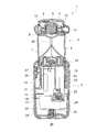
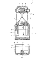
- FIG. 1 is an exploded perspective view showing an example of a light
- FIG. 2 is a longitudinal sectional view of the light
- the light 1 includes an upper illumination unit 2 and a lower battery holding unit 3.
- the illumination unit 2 includes a cylindrical and transparent lower lens 4, a light unit 5 provided above the lower lens 4 and including an LED, and a cap-shaped transparent upper lens provided above the light unit 5.
- a conical reflector 7 fixed to the upper surface of the battery holding unit 3 is disposed on the lower side of the lower lens 4.
- the light unit 5 is held by a holder 9 at the center of a ring 8 that partitions the lower lens 4 and the upper lens 6.
- the holder 9 has a pair of shafts 10, 10 protruding in a point-symmetric position. Is held by the ring 8 so that it can rotate around the shafts 10 and 10.
- One shaft 10 is connected to a knob 11 protruding outside the ring 8. By rotating the holder 9 by operating the knob 11, the direction of the light unit 5 can be selected either up or down. Yes. That is, if the light unit 5 is directed upward, the light from the LED is irradiated upward via the upper lens 6, so that the battery holder 3 can be gripped and used as a flashlight (flashlight).
- the light unit 5 is directed downward, the light of the LED is irradiated downward, diffused radially by the reflector 7, and irradiated to the surroundings via the lower lens 4, so that it can be used as a lantern.
- a base end of a hook 12 as a hanging tool is rotatably connected to the ring 8, and a storage position where the tip of the hook 12 fits in a lower end of the illumination unit 2 as shown in FIGS. Since the drawer position located above the illumination unit 2 can be arbitrarily selected, when used as a lantern, it can be hung on a wall or the like using the hook 12 at the drawer position.
- the housing of the battery holding unit 3 is divided into a cylindrical upper housing 13 and a lower housing 14, and the upper and lower housings 13, 14 are arranged in the lower end of the upper housing 13.
- the male screw part 15 formed on the outer periphery of the lower housing 14 can be coupled to the female screw part 15 formed on the periphery by screwing.
- An O-ring 17 serving as a seal member is externally provided at the base of the male screw portion 16, and the O-ring 17 is brought into contact with the end portion of the female screw portion 15 and deforms in a coupled state of the upper and lower housings 13 and 14.
- the mating surfaces 13 and 14 are sealed.
- An inner holder 18 having a terminal portion (not shown) at the upper end of the inner surface is screwed into the upper housing 13, and a push button 19 that is urged upward by a coil spring 20 at the center of the bottom of the lower housing 14. Is provided. Therefore, a housing part 21 for the battery 22 is formed between the inner holder 18 and the lower housing 14 in the battery holding part 3.
- the battery 22 is charged by a dedicated charger and used as a power source for electric tools such as impact drivers and driver drills.
- a case containing a plurality of lithium ion batteries is inserted into a housing of the electric tool, and is attached.
- An insertion portion 23 having a terminal portion (not shown) on the upper surface and a large diameter portion 24 formed at the lower end of the insertion portion 23 are formed.
- the insertion portions 23 are inserted into the left and right side surfaces of the large diameter portion 24.
- Locking claws 25 that can be locked to the housing of the electric tool in the state are formed. Therefore, when this battery 22 is attached to the electric tool, only the insertion portion 23 is hidden in the housing of the electric tool, and the large diameter portion 24 is exposed to the outside.
- the accommodating portion 21 formed in the battery holding portion 3 can accommodate the entire battery 22. That is, when the lower housing 14 is coupled to the upper housing 13 with the insertion portion 23 inserted into the inner holder 18 of the upper housing 13, the battery 22 is completely covered by the upper and lower housings 13, 14.
- a push button switch 26 is provided between the inner holder 18 and the upper housing 13, and a rubber switch cover 27 is provided on the upper housing 13 outside the push button switch 26.
- 28 is a conductor that supplies power from the battery holding unit 3 to the light unit 5
- 29 is a bumper attached to the peripheral surface and bottom surface of the lower housing 14.
- the housing part 21 is as described above.
- the battery 22 is accommodated in the battery.
- the terminal portion provided on the upper surface of the insertion portion 23 is electrically connected to the terminal portion of the inner holder 18.
- the push button 19 of the lower housing 14 abuts against the bottom surface of the large-diameter portion 24 and presses the battery 22 upward to maintain the contact between the terminal portions. Therefore, even when a battery 22A having a small capacity is used as shown in FIG. 4, the push button 19 protrudes to push up the battery 22A, so that there is no problem in electrical connection.
- the switch cover 27 when the switch cover 27 is pressed to turn on the push button switch 26, the LED is turned on and can be used as a flashlight or a lantern. Further, since the battery 22 is completely covered with the upper and lower housings 13 and 14 and is not exposed to the outside, the joint portion of the upper and lower housings 13 and 14 is sealed by the O-ring 17 so that the waterproofness of the battery holding portion 3 is maintained. Thus, there is no possibility that water or the like enters the housing portion 21.
- the entire power tool battery 22 serving as a power source is accommodated in the upper and lower housings 13 and 14, even when the power tool battery 22 is used as a power source. It has a good waterproof function and is easy to use.
- the battery 22 (22A) is provided with a terminal portion on one surface and is electrically connected, the terminal portion is not exposed in the electrically connected state. In this state, the entire battery 22 (22A) is accommodated in the housing, so that higher waterproofness can be obtained.
- the housing is divided so that the housing portion 21 can be opened and closed, and an O-ring 17 that seals the housing portion 21 in a combined state of the upper and lower housings 13 and 14 is provided on the mating surfaces of the divided upper and lower housings 13 and 14.
- waterproofness can be secured even if the housing is divided.
- the upper and lower housings are completely separated and screwed together.
- bayonet coupling is adopted, or the lower housing is hinged to the upper housing and provided on the lower housing. It may be possible to open and close the accommodating part by engaging and disengaging a locking part such as a hook, or a structure in which the upper and lower housings are simply inserted and joined together.
- the light in the above form can be used by selecting either a flashlight or a lantern, but the present invention can be applied even if it has only one of the functions.
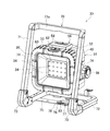
- FIG. 5 is a perspective view showing another form of the light
- FIG. 6 is a longitudinal sectional view of the light
- the light 30 is a stationary type (so-called a so-called light body 31) and a frame 70 that supports the light body 31. Floodlight).
- the light body 31 is provided with a substrate 33 provided with a plurality of LEDs 34, 34,... In a vertical direction in a front housing 32 having a square shape when viewed from the front (the right side in FIG. 6 is the front).
- a transparent plate 35 is fitted on the front surface of the front housing 32.
- Reference numeral 36 denotes a reflector provided between the substrate 33 and the transparent plate 35. Further, as shown in FIG.
- the rear upper portion of the front housing 32 is a rearwardly inclined surface 37, and a mounting portion 38 of the battery 41 is recessed in the center of the inclined surface 37. Further, a rectangular frame portion 39 surrounding the mounting portion 38 is formed on the rear surface of the front housing 32, and a seal member 40 is provided on the rear surface of the frame portion 39 over the entire periphery from the rear surface of the frame portion 39. It is buried in a protruding state.
- the battery 41 used here is also charged with a dedicated charger and used as a power source for an electric power tool such as an impact driver or a driver drill.
- the battery 41 has a rectangular box-like case 42 containing a plurality of lithium ion batteries.
- 43 is provided with a locking claw 44 that is projected and biased. That is, when the slide rail 43 is fitted between the guide rails of the housing of the electric tool and slid until the locking claw 44 is locked to the housing, a terminal portion (not shown) provided on the upper surface between the slide rails 43 and 43 is provided. It is electrically connected to the terminal portion on the power tool side.
- a pair of left and right guide rails 45, 45 which are the same as the electric power tool, protrude in the vertical direction on both the left and right sides of the mounting portion 38, and a terminal board in the vertical direction is provided between the guide rails 45, 45.
- a terminal block 46 having 47 is provided.
- a recessed portion 48 in which the locking claw 44 can be locked is formed above the terminal block 46. Therefore, when the battery 41 is slid from above so that the slide rails 43 and 43 are fitted between the guide rails 45 and 45 and is pushed downward until the locking claw 44 is locked to the recess 48, FIGS. As shown, the battery 41 is mounted vertically on the mounting portion 38, and the terminal plate 47 of the terminal block 46 is electrically connected to the terminal portion of the battery 41.
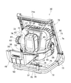
- a rear housing 49 is provided behind the front housing 32.
- the rear housing 49 is continuous with the upper surface portion 50 that is continuous with the upper surface of the front housing 32, the side surface portions 51, 51 that are continuous with the left and right side surfaces of the front housing 32, and the lower portion of the rear surface of the front housing 32.
- a rear surface portion 52 the front surface of which is cut in an inclined shape in accordance with the inclined surface 37 of the front housing 32, and the lower end thereof is rotatably connected by a horizontal shaft 53 provided below the mounting portion 38. Has been. Therefore, the rear housing 49 is in the closed position shown in FIGS.
- a rib 54 is provided in the rear housing 49 so as to be in contact with the frame portion 39 of the front housing 32 at the closed position over the entire circumference.
- the battery 41 is formed by the rib 54 and the mounting portion 38.
- a housing portion 55 is formed to cover the whole. In this state, when the sealing member 40 comes into contact with the end face of the rib 54, the accommodating portion 55 is sealed.
- a well-known latch 56 that is hinged in the order of the lever plate 57 and the hook plate 58 is provided on the upper surface portion 50 of the rear housing 49, and the hook plate 58 can be locked on the upper surface of the front housing 32.
- a hook 59 is erected.
- Reference numeral 60 denotes a protective frame that covers the entire front end of the front housing 32, and a button portion 62 positioned above the push button switch 61 provided in the front housing 32 is formed on the upper portion of the protective frame 60. ing.
- the push button switch 61 is electrically connected to the controller 63 provided in front of the terminal block 46 together with the LED 34.
- a nut member 64 having a 1/2 inch screw hole opened downward is provided at the bottom of the front housing 32 at a position near the rear (directly below the battery 41) in the center in the left-right direction.
- circular protrusions 65, 65 project from the left and right side surfaces of the front housing 32, and screws (not shown) each having a knob 66 on the head are screwed into the center of the circular protrusion 65.
- the frame 70 is formed by connecting ends of the U-shaped upper frame 71 and the U-shaped lower frame 72 via elbows 73, 73 that are L-shaped in side view.
- the frame 71 is erected in a vertical direction with a slight inclination behind it, and the lower frame 72 is in a horizontal direction.
- connecting plates 74 and 74 having hooks at the ends are fixed rearwardly.
- the connecting plates 74 and 74 are screwed into the left and right circular protrusions 65 of the light body 31.
- the light main body 31 is supported so as to be rotatable at a position floating from the lower frame 72 behind the upper frame 71, and if the screw is screwed in by rotating the knob 66, the circular protrusion 65
- the rotation of the light main body 31 can be restricted by sandwiching the connecting plate 74 between the knob 66 and the knob 66. If the screw is loosened by rotating the knob 66, the light main body 31 can be rotated around the screw serving as the axis in the left-right direction to adjust the direction (angle) of the light main body 31.
- the handle 71a is a handle formed at the upper end of the upper frame 71, and the handle 71a is formed integrally with the frame 70 in this way, so that the handle and the frame are compact and easy to use compared to providing the handle and the frame separately. Become.
- a plate-like bar 75 that runs right under the light main body 31 is installed in the left-right direction.
- a nut 76 having a 5/8 inch screw hole is attached to the center of the bar 75 with the screw hole opened downward.
- 77 is a folded plate in which the tip of the lower piece 78 is fitted on the nut 76 on the upper surface of the bar 75, and the tip of the upper piece 79 is positioned above the nut 76.
- the tip of the upper piece 79 is the nut 76.
- a through hole 80 having a diameter smaller than that of the screw hole is formed in a washer shape.
- the battery 41 is inserted into the mounting portion 38 from above as described above. After mounting, when the rear housing 49 is rotated to the closed position and the latch 56 is applied, the battery 41 is completely covered with the rear housing 49 and is not exposed to the outside. At this time, since the accommodating portion 55 of the battery 41 is sealed by the sealing member 40, the waterproofness of the accommodating portion 55 is maintained, and there is no possibility that water or the like enters. Then, when the frame 70 is placed on the ground or the like and the button unit 62 is pressed to turn on the push button switch 61, the LED 34 is turned on and the front is irradiated.
- the controller 63 monitors the voltage of the battery 41. When the voltage of the battery 41 reaches a threshold value or less by use, the controller 63 turns off some LEDs 34 and confirms that the remaining capacity of the battery 41 is small. It has come to inform. In this case, the remaining LEDs 34 may continue to be lit without changing the light amount, or may be lit continuously with the light amount reduced to save power.
- the control is not limited to turning off some of the LEDs 34 and notifying, and if the voltage drops below a threshold value, the amount of light of all the LEDs 34 may be reduced and notified.
- the entire battery 41 for the electric tool serving as the power source is accommodated in the front and rear housings 32 and 49, and therefore the battery 41 for the electric tool is used as the power source.
- the battery 41 has a good waterproof function and is easy to use.
- the battery 41 since the battery 41 includes a terminal portion on one surface and is electrically connected, the terminal portion is not exposed in the electrically connected state. In this state, since the entire battery 41 is accommodated in the front and rear housings 32 and 49, higher waterproofness can be obtained.
- the housing is divided so that the housing portion 55 can be opened and closed, and the sealing member 40 that seals the housing portion 55 in a combined state of the front and rear housings 32 and 49 is provided on the mating surfaces of the divided front and rear housings 32 and 49.
- waterproofness can be secured even if the housing is divided.
- the rear housing is connected by the lower shaft so that the housing portion can be opened and closed.
- the rear housing may be connected by either the left or right shaft or the upper shaft.
- the battery is not limited to the slide-mounting type as in the above-described embodiment, but may be the plug-in mounting type described in the first embodiment.
- the frame can be omitted as well as the shape of the frame.
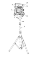
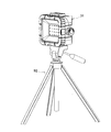
- the light 30 can be used as a stationary type by placing the frame 70 directly on the ground or the like, or can be placed using a dedicated tripod stand 81 as shown in FIG.
- This tripod stand 81 has a support bar 83 on which the bar 75 of the frame 70 can be placed orthogonally fixed to the tip of a telescope-type support 82 that can be vertically expanded and contracted. Then, the knob screw 84 can be penetrated and screwed into the support 82.
- the knob screw 84 is smaller in diameter than the screw hole of the nut 76.
- the knob screw 84 is connected to the upper piece 79, the nut 76,
- the side piece 78 and the bar 75 are passed through in this order and screwed into the column 82 and tightened, the bar 75 is pressed against the support bar 83 via the nut 76 and the folded plate 77 and the frame 70 is supported on the column 82. Therefore, the light main body 31 can irradiate light from above the column 82.
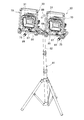
- the tripod stand 81 can support the two lights 30, 30 by using the attachment 85 shown in FIG.
- This attachment 85 is provided with a long bar 86 placed on the support bar 83 and fixed at the center with a thumbscrew 84.
- the two lights 30, 30 placed on both ends of the long bar 86 are Each can be connected with knob screws 87 and 87 in the same manner as in FIG.
- Reference numeral 88 denotes a handle provided at the center of the long bar 86 through which the knob screw 84 penetrates from above.
- Reference numeral 89 denotes a base bar that is orthogonally connected to the lower surfaces of both ends of the long bar 86.
- the base bar 89 is a light bar. Since the long bar 86 is floated and supported from the ground or the like in a state where the attachment 85 is placed on the ground or the like in order to attach 30, the knob screw 87 can be screwed into the long bar 86.
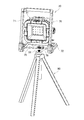
- a tripod stand 90 shown in FIG. 10 is for attaching a laser marking device, and a 5/8 inch mounting screw 91 protrudes upward from the upper end of the tripod stand 90. 11 is screwed into a nut 76 fixed to the bar 75 of the frame 70, so that the light 30 can be supported by the tripod stand 90 as shown in FIG.
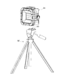
- a tripod stand 92 shown in FIG. 12 is for a camera, and a 1/2 inch mounting screw 93 protrudes upward from the upper end of the tripod stand 92.
- the light main body 31 can be supported by the tripod stand 92 as shown in FIG. 13 by being screwed into the nut member 64 on the bottom surface of the light main body 31 removed from the 70.
- the lighting mode of the LED 34 and the notification control of the remaining capacity decrease of the battery 41 may be as follows. First, here, each time the button unit 62 is pressed, the lighting mode of the LED 34 is switched in the order of “OFF”, “ON (High)”, and “ON (Low)”. Here, when the remaining capacity of the battery 41 decreases during lighting in the low mode with a small amount of light, only one LED 34 (here, blacked out in FIG. 14) is automatically switched from the low mode to the high mode with a large amount of light. The lighting is continued by switching, and the rest is turned off. Further, if the remaining capacity of the battery 41 decreases during lighting in the High mode, the lighting of only one LED 34 is continued in the High mode, and the rest is turned off. As a result, a decrease in remaining capacity can be notified.
- the six lamps surrounded by the frame A shown in FIG. 14 have higher visibility than the 14 lamps positioned around the six lamps. That is, it is easy to see even when working at a location oblique to the front of the light, and it is possible to reliably notify the operator of a decrease in capacity. Further, since it is far from the reflector 36 that is at a high temperature, the heat dissipation efficiency is good and the remaining capacity can be used effectively. That is, since there is little loss due to heat, it can be lit longer and the time for the operator to replace the battery can be extended.
- 2 lamps (2 lamps surrounded by the frame B) located in the center of the irradiation surface are considered to have the highest effect.
- One is selected.
- lighting is not limited to one lamp when the remaining capacity is reduced. For example, lighting of two lamps in frame B is continued together, or lighting of all six lamps in frame A is continued. It is possible to continue.
- the remaining capacity notification control when the battery voltage reaches a threshold value or less, at least one lamp is continuously turned on and the remaining lights are turned off, thereby effectively using the remaining capacity. Thus, it is possible to reliably notify the operator of a decrease in the remaining capacity. In particular, by selecting the LED that continues to be lit from the one close to the center of the irradiation surface, high visibility can be obtained and the remaining capacity can be used more effectively.
Abstract
【課題】電動工具用のバッテリーを電源として用いた場合でも良好な防水機能を有し、使い勝手に優れるライトを提供する。 【解決手段】ライト1は、上側の照明部2と下側のバッテリー保持部3とからなり、上下ハウジング13,14に分割されるバッテリー保持部3には、電動工具用のバッテリー22が電源として使用される。すなわち、バッテリー22の挿入部23を上ハウジング13の内側ホルダ18に差し込んだ状態で、上ハウジング13に下ハウジング14を結合させると、バッテリー22は上下ハウジング13,14によって完全に覆われるようになっている。
Description
本発明は、電動工具用のバッテリーを電源として用いるライトに関する。
ライトは、特許文献1に開示のように、LED等の照明体を備えた本体に、電源となるバッテリーを装着したものが知られている。このバッテリーは、電動工具に用いられるものと同じで、本体には、電動工具と同じ形態のバッテリー装着部が形成されて、そのバッテリー装着部にバッテリーが着脱可能となっている。
上記従来のライトにおいては、バッテリー装着部にバッテリーを装着した状態では、結合部分を除いてバッテリーが露出した状態となる。しかし、バッテリー装着部とバッテリーとの間には防水構造が施されていないため、ユーザは当該バッテリーに水等が掛からないように注意して取り扱う必要があった。
そこで、本発明は、電動工具用のバッテリーを電源として用いた場合でも良好な防水機能を有し、使い勝手に優れるライトを提供することを目的としたものである。
上記目的を達成するために、請求項1に記載の発明は、電動工具用のバッテリーを電源として用い、前記バッテリー全体をハウジング内に収容してなることを特徴とする。
請求項2に記載の発明は、請求項1の構成において、前記バッテリーは、一つの面に端子部を備えて電気的接続されることを特徴とする。
請求項3に記載の発明は、請求項1又は2の構成において、前記ハウジングを、前記バッテリーの収容部を開閉可能に分割し、分割したハウジング同士の合わせ面に、前記分割したハウジングの結合状態で前記収容部をシールするシール部材を設けたことを特徴とする。
請求項4に記載の発明は、請求項1の構成において、前記ハウジングの上部に照明部を備え、前記照明部に吊り下げ具を設けたことを特徴とする。
請求項5に記載の発明は、請求項4の構成において、前記照明部は、円筒状の下レンズと、その下レンズの上方に設けられるライトユニットと、そのライトユニットの上方に設けられる上レンズと、を備え、前記ライトユニットは、回転可能となって照射の向きを上下何れかに選択可能であることを特徴とする。
請求項6に記載の発明は、請求項5の構成において、前記下レンズ内の下側に、リフレクタが配置されることを特徴とする。
請求項7に記載の発明は、請求項3の構成において、前記ハウジングを上下に二分割して、前記シール部材を、上下ハウジングの合わせ面をシールするOリングとしたことを特徴とする。
請求項8に記載の発明は、請求項7の構成において、前記バッテリーは、上ハウジング内に設けた内側ホルダに対して差し込み装着されることを特徴とする。
請求項9に記載の発明は、前記バッテリーは、リチウムイオン電池を内蔵することを特徴とする。
請求項10に記載の発明は、請求項1又は2の構成において、前方に光を照射可能なライト本体を、接地可能なフレームに対して左右方向の軸を中心に角度調整可能に連結したことを特徴とする。
請求項11に記載の発明は、請求項10の構成において、前記ハウジングを、前記バッテリーの収容部を開閉可能に前後へ二分割し、分割した前後ハウジング同士の合わせ面に、前記前後ハウジングの結合状態で前記収容部をシールするシール部材を設けたことを特徴とする。
請求項12に記載の発明は、請求項11の構成において、前記後ハウジングを前記前ハウジングに対して回転可能に連結したことを特徴とする。
請求項13に記載の発明は、請求項11又は12の構成において、前記バッテリーは、前記前ハウジングの後面に設けた装着部に対して上方からスライド装着されることを特徴とする。
請求項14に記載の発明は、請求項10の構成において、前記フレームを着脱可能としたことを特徴とする。
請求項15に記載の発明は、請求項14の構成において、前記ライト本体の下面に、三脚スタンドを接続可能なナット部材を設けて、前記フレームを取り外した前記ライト本体を前記三脚スタンドで支持可能としたことを特徴とする。
請求項16に記載の発明は、請求項10の構成において、前記フレームの下面に、三脚スタンドを接続可能なナットを設けて、前記フレームを前記三脚スタンドで支持可能としたことを特徴とする。
請求項1に記載の発明によれば、電動工具用のバッテリーを電源として用いた場合でも良好な防水機能を有し、使い勝手に優れたものとなる。
請求項2に記載の発明によれば、請求項1の効果に加えて、バッテリーは一つの面にまとめて端子部を備えているので、電気的接続した状態で端子部は露出しない。この状態でバッテリー全体がハウジング内に収容されるため、一層高い防水性を得ることができる。
請求項3に記載の発明によれば、請求項1又は2の効果に加えて、シール部材の採用により、ハウジングを分割しても防水性を確保することができる。
請求項4~9に記載の発明によれば、請求項1の効果に加えて、ランタンとして好適に使用できる。
請求項10~16に記載の発明によれば、上記効果に加えて、投光器として好適に使用できる。
請求項2に記載の発明によれば、請求項1の効果に加えて、バッテリーは一つの面にまとめて端子部を備えているので、電気的接続した状態で端子部は露出しない。この状態でバッテリー全体がハウジング内に収容されるため、一層高い防水性を得ることができる。
請求項3に記載の発明によれば、請求項1又は2の効果に加えて、シール部材の採用により、ハウジングを分割しても防水性を確保することができる。
請求項4~9に記載の発明によれば、請求項1の効果に加えて、ランタンとして好適に使用できる。
請求項10~16に記載の発明によれば、上記効果に加えて、投光器として好適に使用できる。
以下、本発明の実施の形態を図面に基づいて説明する。
[形態1]
図1は、ライトの一例を示す分解斜視図、図2はライトの縦断面図で、ライト1は、上側の照明部2と下側のバッテリー保持部3とからなる。まず照明部2は、円筒状で透明な下レンズ4と、その下レンズ4の上方に設けられてLEDを備えたライトユニット5と、ライトユニット5の上方に設けられるキャップ状の透明な上レンズ6とを備える。下レンズ4内の下側には、バッテリー保持部3の上面に固定される円錐状のリフレクタ7が配されている。
[形態1]
図1は、ライトの一例を示す分解斜視図、図2はライトの縦断面図で、ライト1は、上側の照明部2と下側のバッテリー保持部3とからなる。まず照明部2は、円筒状で透明な下レンズ4と、その下レンズ4の上方に設けられてLEDを備えたライトユニット5と、ライトユニット5の上方に設けられるキャップ状の透明な上レンズ6とを備える。下レンズ4内の下側には、バッテリー保持部3の上面に固定される円錐状のリフレクタ7が配されている。
ライトユニット5は、下レンズ4と上レンズ6との間を仕切るリング8の中央でホルダ9に保持されているが、このホルダ9は、点対称位置に突設された一対の軸10,10がリング8に保持されることで、軸10,10を中心に回転可能となっている。一方の軸10には、リング8の外側に突出するツマミ11が連結されており、ツマミ11の操作によってホルダ9を回転させることで、ライトユニット5の向きを上下何れかに選択可能となっている。すなわち、ライトユニット5を上向きとすれば、LEDの光が上レンズ6を介して上方へ照射されるため、バッテリー保持部3を把持してフラッシュライト(懐中電灯)として使用できる。
一方、ライトユニット5を下向きとすれば、LEDの光が下向きに照射され、リフレクタ7によって放射状に拡散し、下レンズ4を介して周囲に照射されるため、ランタンとして使用できる。リング8には、吊り下げ具としてのフック12の基端が回転可能に連結されて、図1,2のようにフック12の先端が照明部2の下端に収まる収納位置と、フック12の先端が照明部2の上方に位置する引き出し位置とが任意に選択可能となっているため、ランタンとして使用する場合は、引き出し位置のフック12を利用して壁等に吊り下げることができる。
次に、バッテリー保持部3のハウジングは、図3にも示すように、筒状の上ハウジング13と下ハウジング14とに二分割されており、上下ハウジング13,14は、上ハウジング13の下端内周に形成した雌ネジ部15に、下ハウジング14の上端外周に形成した雄ネジ部16を螺合させることで結合可能となっている。雄ネジ部16の根元には、シール部材としてのOリング17が外装されて、上下ハウジング13,14の結合状態でOリング17が雌ネジ部15の端部と当接して変形し、上下ハウジング13,14の合わせ面をシールするものとなる。
また、上ハウジング13内には、内面上端に図示しない端子部を備えた内側ホルダ18がネジ止めされて、下ハウジング14の底部中央には、コイルバネ20によって上方へ突出付勢される押圧ボタン19が設けられている。
よって、バッテリー保持部3内で内側ホルダ18と下ハウジング14との間には、バッテリー22の収容部21が形成される。
また、上ハウジング13内には、内面上端に図示しない端子部を備えた内側ホルダ18がネジ止めされて、下ハウジング14の底部中央には、コイルバネ20によって上方へ突出付勢される押圧ボタン19が設けられている。
よって、バッテリー保持部3内で内側ホルダ18と下ハウジング14との間には、バッテリー22の収容部21が形成される。
バッテリー22は、専用の充電器で充電され、インパクトドライバやドライバドリル等の電動工具の電源として使用されるもので、複数のリチウムイオン電池を内蔵したケースは、電動工具のハウジングに差し込み装着され、上面に図示しない端子部を備えた挿入部23と、その挿入部23の下端に形成される大径部24とに形成され、大径部24の左右の側面には、挿入部23を差し込んだ状態で電動工具のハウジングに係止可能な係止爪25が形成されている。よって、このバッテリー22を電動工具に装着した場合は、挿入部23のみが電動工具のハウジング内に隠れて大径部24は外部に露出した状態となる。
しかし、バッテリー保持部3内に形成される収容部21は、このバッテリー22全体を収容可能となっている。すなわち、挿入部23を上ハウジング13の内側ホルダ18に差し込んだ状態で、上ハウジング13に下ハウジング14を結合させると、バッテリー22は上下ハウジング13,14によって完全に覆われるようになっている。
また、内側ホルダ18と上ハウジング13との間には、押しボタンスイッチ26が設けられ、押しボタンスイッチ26の外側で上ハウジング13には、ゴム製のスイッチカバー27が設けられている。28は、バッテリー保持部3からライトユニット5へ電力を供給する導電体、29は下ハウジング14の周面及び底面に被着されたバンパである。
また、内側ホルダ18と上ハウジング13との間には、押しボタンスイッチ26が設けられ、押しボタンスイッチ26の外側で上ハウジング13には、ゴム製のスイッチカバー27が設けられている。28は、バッテリー保持部3からライトユニット5へ電力を供給する導電体、29は下ハウジング14の周面及び底面に被着されたバンパである。
以上の如く構成されたライト1においては、下ハウジング14を取り外して収容部21を開放した状態で、バッテリー22を内側ホルダ18に差し込んで下ハウジング14をねじ込み結合すると、前述のように収容部21にバッテリー22が収容される。この状態では、挿入部23の上面に設けた端子部が内側ホルダ18の端子部と電気的に接続される。このとき下ハウジング14の押圧ボタン19が大径部24の底面に当接してバッテリー22を上方へ押圧し、端子部同士の接触を維持させる。従って、図4に示すように容量が小さいバッテリー22Aを用いた場合でも、押圧ボタン19が突出してバッテリー22Aを押し上げるため、電気的接続に支障は生じない。
よって、スイッチカバー27を押して押しボタンスイッチ26をONさせると、LEDが点灯し、フラッシュライト又はランタンとして使用できる。
また、バッテリー22は上下ハウジング13,14で完全に覆われて外部へ露出しない上、上下ハウジング13,14の結合部分はOリング17によってシールされているため、バッテリー保持部3の防水性は保持され、収容部21内に水等が侵入するおそれはなくなる。
また、バッテリー22は上下ハウジング13,14で完全に覆われて外部へ露出しない上、上下ハウジング13,14の結合部分はOリング17によってシールされているため、バッテリー保持部3の防水性は保持され、収容部21内に水等が侵入するおそれはなくなる。
このように、上記形態1のライトによれば、電源となる電動工具用のバッテリー22全体を上下ハウジング13,14内に収容しているので、電動工具用のバッテリー22を電源として用いた場合でも良好な防水機能を有し、使い勝手に優れたものとなる。
特にここでは、バッテリー22(22A)は、一つの面に端子部を備えて電気的接続されるものとなっているので、電気的接続した状態で端子部は露出しない。この状態でバッテリー22(22A)全体がハウジング内に収容されるため、一層高い防水性を得ることができる。
また、ハウジングを、収容部21を開閉可能に分割し、分割した上下ハウジング13,14同士の合わせ面に、上下ハウジング13,14の結合状態で収容部21をシールするOリング17を設けたことで、ハウジングを分割しても防水性を確保することができる。
特にここでは、バッテリー22(22A)は、一つの面に端子部を備えて電気的接続されるものとなっているので、電気的接続した状態で端子部は露出しない。この状態でバッテリー22(22A)全体がハウジング内に収容されるため、一層高い防水性を得ることができる。
また、ハウジングを、収容部21を開閉可能に分割し、分割した上下ハウジング13,14同士の合わせ面に、上下ハウジング13,14の結合状態で収容部21をシールするOリング17を設けたことで、ハウジングを分割しても防水性を確保することができる。
なお、上記形態では、上下ハウジングを完全に分離してネジ結合としているが、結合時の防水性が維持できれば、バヨネット結合を採用したり、下ハウジングを上ハウジングにヒンジ結合して下ハウジングに設けたフック等の係止部を係脱させることで収容部を開閉できるようにしたり、単純に上下ハウジング同士を差し込み結合する構造を採用したりしてもよい。
また、上記形態のライトはフラッシュライトとランタンとを選択して使用できるようになっているが、どちらか一方のみの機能を有するものであっても本発明の適用は可能である。
また、上記形態のライトはフラッシュライトとランタンとを選択して使用できるようになっているが、どちらか一方のみの機能を有するものであっても本発明の適用は可能である。
[形態2]
図5は、ライトの他の形態を示す斜視図、図6はライトの縦断面図で、このライト30は、ライト本体31と、そのライト本体31を支持するフレーム70とからなる定置型(いわゆる投光器)となっている。まずライト本体31は、正面視が四角形状の前ハウジング32内に、前面(図6の右側を前方とする。)に複数のLED34,34・・を設けた基板33を上下方向に設置し、前ハウジング32の前面に透明板35を嵌着してなる。36は、基板33と透明板35との間に設けられたリフレクタである。
また、前ハウジング32の後面上部は、図7にも示すように後下がりの傾斜面37となっており、その傾斜面37の中央に、バッテリー41の装着部38が凹設されている。さらに、前ハウジング32の後面には、装着部38を囲む四角形状の枠部39が形成され、その枠部39の後面には、全周に亘ってシール部材40が、枠部39の後面から突出する状態で埋設されている。
ここで使用されるバッテリー41も、専用の充電器で充電され、インパクトドライバやドライバドリル等の電動工具の電源として使用されるもので、複数のリチウムイオン電池を内蔵した四角箱状のケース42の上面(図6では右側が上面となっている。)には、電動工具のハウジングに形成した一対のガイドレール間に嵌合する左右一対のスライドレール43,43が形成されて、スライドレール43,43の間には、突出付勢される係止爪44が設けられている。すなわち、スライドレール43を電動工具のハウジングのガイドレール間に嵌合させて係止爪44がハウジングに係止するまでスライドさせると、スライドレール43,43間で上面に設けた図示しない端子部が電動工具側の端子部と電気的接続されるものである。
よって、ここでの装着部38の左右両側には、電動工具と同じ左右一対のガイドレール45,45が上下方向に突設されて、そのガイドレール45,45の間に、上下方向の端子板47を備えた端子台46が設けられている。端子台46の上方には、係止爪44が係止可能な凹部48が形成されている。従って、バッテリー41を、スライドレール43,43がガイドレール45,45間に嵌合するように上方からスライドさせ、係止爪44が凹部48に係止するまで下方へ押し込むと、図6,7に示すようにバッテリー41は装着部38へ縦向きに装着されて端子台46の端子板47がバッテリー41の端子部と電気的接続される。
そして、前ハウジング32の後方には、後ハウジング49が設けられている。この後ハウジング49は、前ハウジング32の上面と連続状となる上面部50と、前ハウジング32の左右の側面と連続状となる側面部51,51と、前ハウジング32の後面下部と連続状となる後面部52とを備え、前面を前ハウジング32の傾斜面37に合わせて傾斜状にカットしたもので、下端が、装着部38の下側に設けた左右方向の軸53によって回転可能に連結されている。よって、後ハウジング49は、図6のように前面が傾斜面37に当接して上面部50及び側面部51が前ハウジング32の上面及び側面とそれぞれ連続する図5,6の閉塞位置と、図7のように傾斜面37から離れて装着部38を開放する開放位置との間で回転可能となる。
また、後ハウジング49の内部には、閉塞位置で前ハウジング32の枠部39と全周に亘って当接するリブ54が立設されて、閉塞位置では、リブ54と装着部38とによってバッテリー41全体を覆う収容部55が形成されるようになっている。この状態でリブ54の端面にシール部材40が当接することで、収容部55がシールされる。
さらに、後ハウジング49の上面部50には、レバー板57とフック板58との順番でヒンジ結合した周知のラッチ56が設けられ、前ハウジング32の上面には、フック板58が係止可能なフック59が立設されている。よって、後ハウジング49の閉塞位置でフック板58の前端をフック59に係止させてフック板58の後端を押し下げると、レバー板57が倒伏してフック板58の係止状態を維持するため、後ハウジング49が閉塞位置でロックされる。
さらに、後ハウジング49の上面部50には、レバー板57とフック板58との順番でヒンジ結合した周知のラッチ56が設けられ、前ハウジング32の上面には、フック板58が係止可能なフック59が立設されている。よって、後ハウジング49の閉塞位置でフック板58の前端をフック59に係止させてフック板58の後端を押し下げると、レバー板57が倒伏してフック板58の係止状態を維持するため、後ハウジング49が閉塞位置でロックされる。
60は、前ハウジング32の前端を全周に亘って覆う保護枠で、保護枠60の上部には、前ハウジング32内に設けられた押しボタンスイッチ61の上側に位置するボタン部62が形成されている。押しボタンスイッチ61は、LED34と共に、端子台46の前方に設けられたコントローラ63に電気的接続されている。
また、前ハウジング32の底部において、左右方向の中央部で後方寄り(バッテリー41の真下)の位置には、1/2インチのネジ穴を下向きに開口させたナット部材64が設けられている。
さらに、前ハウジング32の左右の側面には、円形突起65,65が突設され、その円形突起65の中心に、頭部にツマミ66を備えた図示しないネジがそれぞれ螺合している。
また、前ハウジング32の底部において、左右方向の中央部で後方寄り(バッテリー41の真下)の位置には、1/2インチのネジ穴を下向きに開口させたナット部材64が設けられている。
さらに、前ハウジング32の左右の側面には、円形突起65,65が突設され、その円形突起65の中心に、頭部にツマミ66を備えた図示しないネジがそれぞれ螺合している。
一方、フレーム70は、コ字状の上フレーム71と同じくコ字状の下フレーム72との端部同士を側面視L字状のエルボ73,73を介して連結したもので、この状態で上フレーム71は斜め後ろにやや傾斜した状態で縦向きに立設され、下フレーム72は横向きとなる。上フレーム71の両端には、先端がフック状の連結板74,74がそれぞれ後ろ向きに固定されており、この連結板74,74の先端に、ライト本体31の左右の円形突起65に螺合されるネジを上方から係止させれば、ライト本体31は上フレーム71の後方で下フレーム72から浮いた位置で回転可能に支持され、ツマミ66の回転操作でネジをねじ込めば、円形突起65とツマミ66との間で連結板74を挟持することでライト本体31の回転を規制できる。ツマミ66の回転操作でネジを緩めれば、左右方向の軸となるネジを中心としてライト本体31を回転させてライト本体31の向き(角度)を調整することができる。71aは、上フレーム71の上端に形成されたハンドルで、このようにハンドル71aがフレーム70と一体に形成されることで、ハンドルとフレームとを別々に設けるのに比べてコンパクトで使いやすい構造となる。
また、下フレーム72の両端部間には、ライト本体31の真下を横切る板状のバー75が左右方向に架設されている。このバー75の中央には、図6に示すように、5/8インチのネジ穴を有するナット76が、ネジ穴を下方に開口させた状態で取り付けられている。77は、バー75の上面で下側片78の先端をナット76に外嵌させ、上側片79の先端をナット76の上方に位置させた二つ折り板で、上側片79の先端は、ナット76のネジ穴より小径の透孔80が同軸で形成されたワッシャー形状となっている。
以上の如く構成されたライト30においては、ラッチ56を解除して後ハウジング49を開放位置へ回転させて装着部38を露出させた状態で、前述のように装着部38に上方からバッテリー41を装着した後、後ハウジング49を閉塞位置へ回転させてラッチ56をかけると、バッテリー41は後ハウジング49で完全に覆われて外部へ露出しない状態となる。このとき、バッテリー41の収容部55はシール部材40によってシールされているため、収容部55の防水性は保持され、水等が侵入するおそれはなくなる。
そして、フレーム70を地面等に載置してボタン部62を押して押しボタンスイッチ61をONさせると、LED34が点灯し、前方を照射するものとなる。
そして、フレーム70を地面等に載置してボタン部62を押して押しボタンスイッチ61をONさせると、LED34が点灯し、前方を照射するものとなる。
なお、ここではコントローラ63がバッテリー41の電圧を監視しており、使用によってバッテリー41の電圧が閾値以下に達すると、コントローラ63は一部のLED34を消灯させてバッテリー41の残容量が少ないことを報知するようになっている。この場合、残りのLED34は、光量を変えずにそのまま点灯を継続させてもよいし、電力節約のために光量を落として点灯を継続させるようにしてもよい。但し、一部のLED34を消灯させて報知する制御に限らず、電圧が閾値以下に低下すると全てのLED34の光量を落として報知するようにしても差し支えない。
このように、上記形態2のライト30によれば、電源となる電動工具用のバッテリー41全体を前後ハウジング32,49内に収容しているので、電動工具用のバッテリー41を電源として用いた場合でも良好な防水機能を有し、使い勝手に優れたものとなる。
特にここでは、バッテリー41は、一つの面に端子部を備えて電気的接続されるので、電気的接続した状態で端子部は露出しない。この状態でバッテリー41全体が前後ハウジング32,49内に収容されるため、一層高い防水性を得ることができる。
また、ハウジングを、収容部55を開閉可能に分割し、分割した前後ハウジング32,49同士の合わせ面に、前後ハウジング32,49の結合状態で収容部55をシールするシール部材40を設けたことで、ハウジングを分割しても防水性を確保することができる。
特にここでは、バッテリー41は、一つの面に端子部を備えて電気的接続されるので、電気的接続した状態で端子部は露出しない。この状態でバッテリー41全体が前後ハウジング32,49内に収容されるため、一層高い防水性を得ることができる。
また、ハウジングを、収容部55を開閉可能に分割し、分割した前後ハウジング32,49同士の合わせ面に、前後ハウジング32,49の結合状態で収容部55をシールするシール部材40を設けたことで、ハウジングを分割しても防水性を確保することができる。
なお、上記形態では、後ハウジングを下側の軸で連結して収容部を開閉可能としているが、左右何れかの軸や上側の軸で連結しても差し支えない。
また、バッテリーは、上記形態のようなスライド装着するタイプに限らず、形態1で説明した差し込み装着するタイプであっても採用可能である。
さらに、フレームの形状変更は勿論、フレームを省略することもできる。
また、バッテリーは、上記形態のようなスライド装着するタイプに限らず、形態1で説明した差し込み装着するタイプであっても採用可能である。
さらに、フレームの形状変更は勿論、フレームを省略することもできる。
一方、ライト30は、フレーム70を直接地面等に載置することで定置型として使用する他、図8に示すように、専用の三脚スタンド81を利用して定置することもできる。この三脚スタンド81は、テレスコープ型で上下方向に伸縮可能とした支柱82の先端に、フレーム70のバー75を載置可能な支持バー83を直交状に固着したもので、支持バー83の中央では、ツマミネジ84を貫通させて支柱82にねじ込み可能となっている。このツマミネジ84は、ナット76のネジ穴よりも径の小さいもので、バー75を支持バー83に載置した状態で、二つ折り板77の上側からツマミネジ84を、上側片79、ナット76、下側片78、バー75の順に貫通させて支柱82にねじ込んで締め付けると、バー75がナット76及び二つ折り板77を介して支持バー83に押圧されてフレーム70が支柱82上に支持される。よって、ライト本体31は支柱82の上方から光を照射可能となる。
また、三脚スタンド81では、図9に示すアタッチメント85を用いることで2つのライト30,30を支持することもできる。このアタッチメント85は、支持バー83に載置されて中央がツマミネジ84で固定される長尺バー86を備えたもので、この長尺バー86の両端に載置した2つのライト30,30を、それぞれツマミネジ87,87で図8と同様に連結可能となっている。88は、長尺バー86の中央に設けられてツマミネジ84が上方から貫通するハンドル、89は、長尺バー86の両端下面へそれぞれ直交状に連結されたベースバーで、ベースバー89は、ライト30を取り付けるためにアタッチメント85を地面等に載置した状態で長尺バー86を地面等から浮かせて支持することで、長尺バー86へのツマミネジ87のねじ込みを可能としている。
一方、専用の三脚スタンドの利用に限らず、他の用途の三脚スタンドの使用も可能となっている。図10に示す三脚スタンド90は、レーザー墨出し器を取り付けるためのもので、この三脚スタンド90の上端には、5/8インチの取付ネジ91が上向きに突出していることから、この取付ネジ91をフレーム70のバー75に固定されるナット76に螺合させることで、図11に示すように、三脚スタンド90によってライト30を支持させることができる。
また、図12に示す三脚スタンド92は、カメラ用のもので、この三脚スタンド92の上端には、1/2インチの取付ネジ93が上向きに突出していることから、この取付ネジ93を、フレーム70から取り外したライト本体31の底面のナット部材64に螺合させることで、図13に示すように、三脚スタンド92によってライト本体31を支持させることができる。
また、図12に示す三脚スタンド92は、カメラ用のもので、この三脚スタンド92の上端には、1/2インチの取付ネジ93が上向きに突出していることから、この取付ネジ93を、フレーム70から取り外したライト本体31の底面のナット部材64に螺合させることで、図13に示すように、三脚スタンド92によってライト本体31を支持させることができる。
そして、形態2のライト30において、LED34の点灯モードとバッテリー41の残容量低下の報知制御とは、以下のようであってもよい。
まず、ここではボタン部62を押し操作する度に、「切」「点灯(High)」「点灯(Low)」の順でLED34の点灯モードが切り替えられるようになっている。ここで、光量の小さいLowモードでの点灯時にバッテリー41の残容量が低下すると、1個のLED34(ここでは図14において黒く塗りつぶしたもの)のみをLowモードから光量の大きいHighモードへ自動的に切り替えて点灯を継続させ、残りを消灯させるようにしている。また、Highモードでの点灯時にバッテリー41の残容量が低下すると、同じく1個のLED34のみHighモードのまま点灯を継続させ、残りを消灯させるようにしている。これにより、残容量の低下が報知可能となっている。
まず、ここではボタン部62を押し操作する度に、「切」「点灯(High)」「点灯(Low)」の順でLED34の点灯モードが切り替えられるようになっている。ここで、光量の小さいLowモードでの点灯時にバッテリー41の残容量が低下すると、1個のLED34(ここでは図14において黒く塗りつぶしたもの)のみをLowモードから光量の大きいHighモードへ自動的に切り替えて点灯を継続させ、残りを消灯させるようにしている。また、Highモードでの点灯時にバッテリー41の残容量が低下すると、同じく1個のLED34のみHighモードのまま点灯を継続させ、残りを消灯させるようにしている。これにより、残容量の低下が報知可能となっている。
この残容量低下時に点灯を継続させる1灯は、以下の理由によって選択されている。
まず、図14に示す枠Aで囲まれた6灯は、その周囲に位置する14灯に比べると、視認性が高い。すなわち、ライト正面に対して斜めの場所で作業をしている場合でも見えやすく、確実に作業者に容量低下を報知することができる。また、高温になっているリフレクタ36から遠いため、放熱効率が良く、残り少ない容量を有効に利用できる。すなわち、熱による損失が少ないため、より長く点灯でき、作業者のバッテリー交換のための時間を延ばすことができる。
よって、この枠A内の6灯のうち、照射面の中央に位置する2灯(枠Bで囲まれた2灯)は、これらの効果が最も高いと考えられるため、この2灯のうちの一方を選択したものである。
但し、残容量低下時に点灯を継続させるのは1灯に限らず、例えば枠Bの2灯の点灯を共に継続させたり、枠Aの6灯の点灯を全て継続させる等、複数灯の点灯を継続させることは可能である。
このように、この残容量の報知制御によれば、バッテリー電圧が閾値以下に達すると、少なくとも1灯の点灯を継続させて残りを消灯させるようにしたことで、残容量を有効に利用しつつ、作業者に残容量の低下を確実に報知することができる。
特に、ここでは点灯を継続させるLEDを照射面の中央に近いものから選択したことで、高い視認性が得られると共に、残容量のより有効な利用が可能となっている。
特に、ここでは点灯を継続させるLEDを照射面の中央に近いものから選択したことで、高い視認性が得られると共に、残容量のより有効な利用が可能となっている。
1,30・・ライト、2・・照明部、3・・バッテリー保持部、5・・ライトユニット、13・・上ハウジング、14・・下ハウジング、15・・雌ネジ部、16・・雄ネジ部、17・・Oリング、18・・内側ホルダ、21,55・・収容部、22,41・・バッテリー、23・・挿入部、24・・大径部、31・・ライト本体、32・・前ハウジング、34・・LED、38・・装着部、39・・枠部、40・・シール部材、46・・端子台、49・・後ハウジング、54・・リブ、70・・フレーム、71・・上フレーム、72・・下フレーム。
Claims (16)
- 電動工具用のバッテリーを電源として用い、前記バッテリー全体をハウジング内に収容してなるライト。
- 前記バッテリーは、一つの面に端子部を備えて電気的接続されることを特徴とする請求項1に記載のライト。
- 前記ハウジングを、前記バッテリーの収容部を開閉可能に分割し、分割したハウジング同士の合わせ面に、前記分割したハウジングの結合状態で前記収容部をシールするシール部材を設けたことを特徴とする請求項1又は2に記載のライト。
- 前記ハウジングの上部に照明部を備え、前記照明部に吊り下げ具を設けたことを特徴とする請求項1に記載のライト。
- 前記照明部は、円筒状の下レンズと、その下レンズの上方に設けられるライトユニットと、そのライトユニットの上方に設けられる上レンズと、を備え、前記ライトユニットは、回転可能となって照射の向きを上下何れかに選択可能であることを特徴とする請求項4に記載のライト。
- 前記下レンズ内の下側に、リフレクタが配置されることを特徴とする請求項5に記載のライト。
- 前記ハウジングを上下に二分割して、前記シール部材を、上下ハウジングの合わせ面をシールするOリングとしたことを特徴とする請求項3に記載のライト。
- 前記バッテリーは、上ハウジング内に設けた内側ホルダに対して差し込み装着されることを特徴とする請求項7に記載のライト。
- 前記バッテリーは、リチウムイオン電池を内蔵することを特徴とする請求項1に記載のライト。
- 前方に光を照射可能なライト本体を、接地可能なフレームに対して左右方向の軸を中心に角度調整可能に連結したことを特徴とする請求項1又は2に記載のライト。
- 前記ハウジングを、前記バッテリーの収容部を開閉可能に前後へ二分割し、分割した前後ハウジング同士の合わせ面に、前記前後ハウジングの結合状態で前記収容部をシールするシール部材を設けたことを特徴とする請求項10に記載のライト。
- 前記後ハウジングを前記前ハウジングに対して回転可能に連結したことを特徴とする請求項11に記載のライト。
- 前記バッテリーは、前記前ハウジングの後面に設けた装着部に対して上方からスライド装着されることを特徴とする請求項11又は12に記載のライト。
- 前記フレームを着脱可能としたことを特徴とする請求項10に記載のライト。
- 前記ライト本体の下面に、三脚スタンドを接続可能なナット部材を設けて、前記フレームを取り外した前記ライト本体を前記三脚スタンドで支持可能としたことを特徴とする請求項14に記載のライト。
- 前記フレームの下面に、三脚スタンドを接続可能なナットを設けて、前記フレームを前記三脚スタンドで支持可能としたことを特徴とする請求項10に記載のライト。
Applications Claiming Priority (4)
| Application Number | Priority Date | Filing Date | Title |
|---|---|---|---|
| JP2013122114 | 2013-06-10 | ||
| JP2013-122114 | 2013-06-10 | ||
| JP2013-165404 | 2013-08-08 | ||
| JP2013165404A JP6200724B2 (ja) | 2013-06-10 | 2013-08-08 | ライト |
Publications (1)
| Publication Number | Publication Date |
|---|---|
| WO2014199684A1 true WO2014199684A1 (ja) | 2014-12-18 |
Family
ID=52021990
Family Applications (1)
| Application Number | Title | Priority Date | Filing Date |
|---|---|---|---|
| PCT/JP2014/055942 WO2014199684A1 (ja) | 2013-06-10 | 2014-03-07 | ライト |
Country Status (2)
| Country | Link |
|---|---|
| JP (1) | JP6200724B2 (ja) |
| WO (1) | WO2014199684A1 (ja) |
Cited By (2)
| Publication number | Priority date | Publication date | Assignee | Title |
|---|---|---|---|---|
| US10274149B2 (en) * | 2016-08-02 | 2019-04-30 | Barebones Systems, Llc | Beacon pendant light |
| CN110914589A (zh) * | 2017-07-18 | 2020-03-24 | 株式会社牧田 | 投光器 |
Families Citing this family (3)
| Publication number | Priority date | Publication date | Assignee | Title |
|---|---|---|---|---|
| JP6872773B2 (ja) * | 2016-12-26 | 2021-05-19 | 株式会社パロマ | ガスコンロ用の照明装置及びガス調理システム |
| KR101986339B1 (ko) * | 2019-01-04 | 2019-06-05 | 삼익방폭전기 주식회사 | 방폭 작업등 |
| JP7323431B2 (ja) | 2019-11-07 | 2023-08-08 | 株式会社マキタ | ポータブルライト |
Citations (7)
| Publication number | Priority date | Publication date | Assignee | Title |
|---|---|---|---|---|
| JP3133833U (ja) * | 2007-05-11 | 2007-07-26 | 株式会社 Ml | 懐中電灯 |
| JP2009537946A (ja) * | 2006-05-15 | 2009-10-29 | エルジー・ケム・リミテッド | 防水機能を有するbms |
| JP2009289709A (ja) * | 2008-06-02 | 2009-12-10 | Toshiba Lighting & Technology Corp | 天井直付け形照明装置及び照明装置 |
| JP2010244905A (ja) * | 2009-04-07 | 2010-10-28 | Kenichi Kawagoe | 携帯用ライトおよび液晶シャッタユニット |
| JP3169919U (ja) * | 2011-06-13 | 2011-08-25 | 清美 ▲高▼橋 | 移動型無給電照明装置 |
| JP3180825U (ja) * | 2012-10-26 | 2013-01-10 | 株式会社ポータ工業 | 照明装置 |
| JP2013067006A (ja) * | 2012-12-17 | 2013-04-18 | Makita Corp | バッテリ式電動工具 |
Family Cites Families (5)
| Publication number | Priority date | Publication date | Assignee | Title |
|---|---|---|---|---|
| JP4363329B2 (ja) * | 2005-01-07 | 2009-11-11 | パナソニック電工株式会社 | 携帯電灯 |
| JP4309950B1 (ja) * | 2008-06-09 | 2009-08-05 | 株式会社ロゴスコーポレーション | ランタン |
| JP2010033764A (ja) * | 2008-07-25 | 2010-02-12 | Panasonic Electric Works Co Ltd | 照明器具 |
| JP5448951B2 (ja) * | 2010-03-16 | 2014-03-19 | 株式会社マキタ | アタッチメント付き電動工具の駆動源供給システム |
| JP2012043761A (ja) * | 2010-08-12 | 2012-03-01 | Azumi Seiko Kk | 作業用ライト |
-
2013
- 2013-08-08 JP JP2013165404A patent/JP6200724B2/ja active Active
-
2014
- 2014-03-07 WO PCT/JP2014/055942 patent/WO2014199684A1/ja active Application Filing
Patent Citations (7)
| Publication number | Priority date | Publication date | Assignee | Title |
|---|---|---|---|---|
| JP2009537946A (ja) * | 2006-05-15 | 2009-10-29 | エルジー・ケム・リミテッド | 防水機能を有するbms |
| JP3133833U (ja) * | 2007-05-11 | 2007-07-26 | 株式会社 Ml | 懐中電灯 |
| JP2009289709A (ja) * | 2008-06-02 | 2009-12-10 | Toshiba Lighting & Technology Corp | 天井直付け形照明装置及び照明装置 |
| JP2010244905A (ja) * | 2009-04-07 | 2010-10-28 | Kenichi Kawagoe | 携帯用ライトおよび液晶シャッタユニット |
| JP3169919U (ja) * | 2011-06-13 | 2011-08-25 | 清美 ▲高▼橋 | 移動型無給電照明装置 |
| JP3180825U (ja) * | 2012-10-26 | 2013-01-10 | 株式会社ポータ工業 | 照明装置 |
| JP2013067006A (ja) * | 2012-12-17 | 2013-04-18 | Makita Corp | バッテリ式電動工具 |
Cited By (3)
| Publication number | Priority date | Publication date | Assignee | Title |
|---|---|---|---|---|
| US10274149B2 (en) * | 2016-08-02 | 2019-04-30 | Barebones Systems, Llc | Beacon pendant light |
| CN110914589A (zh) * | 2017-07-18 | 2020-03-24 | 株式会社牧田 | 投光器 |
| US11153951B2 (en) | 2017-07-18 | 2021-10-19 | Makita Corporation | Floodlight |
Also Published As
| Publication number | Publication date |
|---|---|
| JP6200724B2 (ja) | 2017-09-20 |
| JP2015018784A (ja) | 2015-01-29 |
Similar Documents
| Publication | Publication Date | Title |
|---|---|---|
| WO2014199684A1 (ja) | ライト | |
| JP6692880B2 (ja) | ライト | |
| US7267454B2 (en) | Universal chargeable electro-optical illuminating lamp | |
| KR101083927B1 (ko) | 조명장치 및 이를 구비한 전기 스탠드 | |
| US8132943B2 (en) | Adjustable recessed lighting fixture | |
| JP2007335282A (ja) | 照明装置 | |
| US10578285B2 (en) | Portable working light apparatus | |
| US7549770B2 (en) | Module for a flashlight or lantern | |
| WO2019017249A1 (ja) | 投光器 | |
| US7140745B2 (en) | Hand-held chargeable optoelectronic illuminating lamp | |
| JP2008192334A (ja) | 非常用照明器具 | |
| CN116066768A (zh) | 可拆卸式提灯照明装置 | |
| JPH1034565A (ja) | 照明付き電動工具 | |
| US20180231215A1 (en) | Multi-functional pen lights | |
| CA2788295A1 (en) | Folding spotlight | |
| KR20150049802A (ko) | 전원 모듈 교체형 휴대용 전등 | |
| US20060098424A1 (en) | Rechargeable flashlight | |
| CN110296380B (zh) | 灯具散热结构及防爆照明终端 | |
| JP2007141598A (ja) | 非常用懐中電灯および非常用照明装置 | |
| KR20130029191A (ko) | 방범용 랜턴 | |
| JP2012028129A (ja) | 携帯電灯 | |
| KR20180006210A (ko) | 회전형 발광장치 | |
| KR20150063281A (ko) | 휴대용 조명장치 | |
| TWM315296U (en) | Improved structure on rechargeable hand-holding working lamp | |
| CN114110456B (zh) | 一种近远光手电筒 |
Legal Events
| Date | Code | Title | Description |
|---|---|---|---|
| 121 | Ep: the epo has been informed by wipo that ep was designated in this application |
Ref document number: 14810834 Country of ref document: EP Kind code of ref document: A1 |
|
| NENP | Non-entry into the national phase |
Ref country code: DE |
|
| 122 | Ep: pct application non-entry in european phase |
Ref document number: 14810834 Country of ref document: EP Kind code of ref document: A1 |