WO2014192329A1 - 運行管理装置、運行管理方法、車両、車両交通システム及びプログラム - Google Patents
運行管理装置、運行管理方法、車両、車両交通システム及びプログラム Download PDFInfo
- Publication number
- WO2014192329A1 WO2014192329A1 PCT/JP2014/052130 JP2014052130W WO2014192329A1 WO 2014192329 A1 WO2014192329 A1 WO 2014192329A1 JP 2014052130 W JP2014052130 W JP 2014052130W WO 2014192329 A1 WO2014192329 A1 WO 2014192329A1
- Authority
- WO
- WIPO (PCT)
- Prior art keywords
- vehicle
- station
- vehicles
- time
- density
- Prior art date
Links
- 238000007726 management method Methods 0.000 title claims description 162
- 238000001514 detection method Methods 0.000 claims description 20
- 238000004364 calculation method Methods 0.000 description 70
- 230000006870 function Effects 0.000 description 59
- 238000000034 method Methods 0.000 description 46
- 230000008569 process Effects 0.000 description 38
- 238000012545 processing Methods 0.000 description 38
- 238000010586 diagram Methods 0.000 description 34
- 230000000694 effects Effects 0.000 description 27
- 230000005540 biological transmission Effects 0.000 description 13
- 230000008859 change Effects 0.000 description 11
- 238000004891 communication Methods 0.000 description 10
- 238000012937 correction Methods 0.000 description 10
- 230000004044 response Effects 0.000 description 7
- 230000007423 decrease Effects 0.000 description 6
- 230000003111 delayed effect Effects 0.000 description 5
- 229910003460 diamond Inorganic materials 0.000 description 5
- 239000010432 diamond Substances 0.000 description 5
- 230000008030 elimination Effects 0.000 description 3
- 238000003379 elimination reaction Methods 0.000 description 3
- 230000001934 delay Effects 0.000 description 2
- 238000005516 engineering process Methods 0.000 description 2
- 230000010365 information processing Effects 0.000 description 2
- 230000001788 irregular Effects 0.000 description 2
- 230000007257 malfunction Effects 0.000 description 2
- 238000012544 monitoring process Methods 0.000 description 2
- 241000052343 Dares Species 0.000 description 1
- 238000004422 calculation algorithm Methods 0.000 description 1
- 238000004590 computer program Methods 0.000 description 1
- 238000011161 development Methods 0.000 description 1
- 239000012530 fluid Substances 0.000 description 1
- 239000004065 semiconductor Substances 0.000 description 1
- 238000004904 shortening Methods 0.000 description 1
- 238000004088 simulation Methods 0.000 description 1
- 230000007704 transition Effects 0.000 description 1
Images


Classifications
-
- B—PERFORMING OPERATIONS; TRANSPORTING
- B61—RAILWAYS
- B61L—GUIDING RAILWAY TRAFFIC; ENSURING THE SAFETY OF RAILWAY TRAFFIC
- B61L27/00—Central railway traffic control systems; Trackside control; Communication systems specially adapted therefor
- B61L27/10—Operations, e.g. scheduling or time tables
- B61L27/12—Preparing schedules
-
- B—PERFORMING OPERATIONS; TRANSPORTING
- B61—RAILWAYS
- B61L—GUIDING RAILWAY TRAFFIC; ENSURING THE SAFETY OF RAILWAY TRAFFIC
- B61L27/00—Central railway traffic control systems; Trackside control; Communication systems specially adapted therefor
- B61L27/10—Operations, e.g. scheduling or time tables
- B61L27/16—Trackside optimisation of vehicle or train operation
-
- B—PERFORMING OPERATIONS; TRANSPORTING
- B61—RAILWAYS
- B61L—GUIDING RAILWAY TRAFFIC; ENSURING THE SAFETY OF RAILWAY TRAFFIC
- B61L27/00—Central railway traffic control systems; Trackside control; Communication systems specially adapted therefor
- B61L27/40—Handling position reports or trackside vehicle data
Definitions
- the present invention relates to a vehicle traveling on a track, an operation management device that manages the operation of the vehicle, a vehicle traffic system including the vehicle and the operation management device, an operation management method, and a program.
- the special diamond is created so that the density of the specific station where the concentration is expected and the existence of the vehicle at that time becomes “dense”. In this way, even if the user is temporarily concentrated in response to an irregular event, it is possible to provide a transportation service with a close operation interval adapted to the increased number of passengers. .
- the vehicle interval is uniformized as a whole vehicle traffic system. Is obtained.
- the vehicle interval is adjusted according to the number of passengers locally increasing at a specific station and a specific date and time. It is not a technology that enables the adjustment of “dense”.
- the train operation control method described in Patent Document 1 the number of passengers (waiting customers) (congestion level) that actually exist in the station is detected, and the number of passengers for each vehicle is made uniform accordingly.
- the method of adjusting the inter-vehicle distance is used.
- the number of waiting customers at a station is fluid and changes from moment to moment. Accordingly, if adjustment of the driving interval is started after detecting the number of waiting customers at the current time, the response becomes slow, and it may not be possible to appropriately provide the transportation service according to the number of waiting customers.
- the present invention provides an operation management device, an operation management method, a vehicle, a vehicle traffic system, and a program that can solve the above-described problems.
- the operation management device is an operation management device that manages the operation of a plurality of vehicles traveling along a track, and the positions of the plurality of vehicles existing on the track are determined. Based on the vehicle position acquisition unit to be acquired and predetermined congestion information, the plurality of vehicles that specify a reference station that increases the density of the presence of the plurality of vehicles and stop at a station behind the reference station. An interval adjusting unit that sets a waiting time for each rear station, and a departure determining unit that adjusts a departure time for each of the rear stations of the plurality of vehicles based on the waiting time.
- the interval adjustment unit sets the station waiting time longer as the station is closer to the reference station.
- the interval adjusting unit sets the waiting time based on the number of passengers estimated at the reference station.
- the interval adjustment unit is configured to estimate a congestion occurrence time estimated based on the congestion information, and a time when the density of the presence of the vehicle increases.
- the waiting time is set so as to match.
- the interval adjusting unit is installed in the passage from the customer collection point to the station as advance congestion information about a planned customer collection event as the congestion information. Detection information acquired from the detection means for detecting the number of passengers in the passage and the flow thereof, or information indicating the estimated arrival time and the estimated number of arrivals regarding other transportation networks To get.
- a vehicle traffic system receives the identification information, position information, and route information of a predetermined target vehicle from the operation management device of the above aspect and the operation management device, and the target A passenger guidance information system that calculates an estimated arrival time for each station of the vehicle and displays the calculated estimated arrival time on a display screen installed at each station.
- the vehicle is a vehicle that travels along a track, based on a vehicle position acquisition unit that acquires the position of the host vehicle on the track, and predetermined congestion information.
- a station serving as a reference for increasing the density of existence of a plurality of vehicles traveling on the track is specified, and a waiting time for each of the rear stations of the own vehicle that stops at the station behind the reference station is set.
- An interval adjustment unit, and a departure determination unit that adjusts a departure time for each of the rear stations of the host vehicle based on the waiting time.
- an operation management method is an operation management method for managing the operation of a plurality of vehicles traveling along a track, wherein the positions of the plurality of vehicles existing on the track are determined.
- Acquire based on predetermined congestion information, identify a reference station that increases the density of the presence of the plurality of vehicles, and the rear of the plurality of vehicles that stop at the station behind the reference station A standby time for each station is set, and based on the standby time, departure times of the plurality of vehicles at the rear stations are adjusted.
- the program acquires a position of the plurality of vehicles existing on the track by using a computer of the operation management device that manages the operation of the plurality of vehicles traveling along the track.
- Vehicle position acquisition means based on predetermined congestion information, identify a reference station that increases the density of the presence of the plurality of vehicles, and the plurality of vehicles that stop at a station behind the reference station, It functions as an interval adjusting means for setting a waiting time for each rear station, and a departure determining means for adjusting the departure time for each of the rear stations of the plurality of vehicles based on the waiting time.
- the density of provision of transportation services by vehicles can be flexibly changed at a desired time and a desired station.
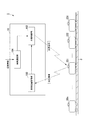
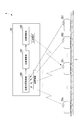
- FIG. 1 is a diagram showing a functional configuration of a vehicle traffic system according to a first embodiment of the present invention.
- reference numeral 1 denotes a vehicle traffic system.
- the vehicle traffic system 1 includes an operation management device 10 and a plurality of vehicles 201, 202,..., 20 n that travel along a track 3 (n is an integer of 2 or more). ).
- the operation management apparatus 10 is called a ground facility, and is an apparatus that controls the operation of a plurality of vehicles 201, 202,.
- the operation management apparatus 10 according to the present embodiment is a functional unit that transmits a departure instruction to each of the vehicles 201, 202,..., 20n based on the determination of the departure determination unit 102 described later.
- the operation management apparatus 10 transmits a departure instruction to each of the vehicles 201 to 20n using a wireless communication unit or the like.
- Each of the vehicles 201 to 20n operates based on a departure instruction received from the operation management device 10.
- operation control based on a safety device (interlocking device) and a traffic light is further added.
- the vehicle 201 is simply based on the operation management device 10 here. It is assumed that the operation control of ⁇ 20n is performed (the case where a security device or the like is used will be described later with reference to FIG. 19).
- the vehicles 201, 202, ..., 20n are trains that travel along a predetermined track 3 (track).
- the vehicles 201 to 20n travel while arriving at and departing from a plurality of stations (not shown in FIG. 1) along the track 3 in accordance with an operation instruction received from the operation management device 10.
- the track 3 is provided with a predetermined position detection device (not shown) at regular intervals, and each of the vehicles 201 to 20n communicates with the position detection device so that the position of the own vehicle on the track 3 can be determined. You can recognize whether you are driving. To explain this function more specifically, each of the vehicles 201 to 20n has its own route database.
- Each of the vehicles 201 to 20n has a function of calculating the travel distance by measuring the tire rotation speed of the host vehicle and grasping the current position of the host vehicle.
- the current position that is grasped from the tire rotation speed due to tire slip or the like may deviate from the actual position.
- the vehicles 201 to 20n correct the deviation while comparing with the position detection device on the ground, so that it is possible to accurately grasp which position on the track 3 the host vehicle is traveling.
- the timetable is determined based on the number of users (the number of passengers) and the amount that can be boarded for each vehicle so that the receiving balance is optimal.
- schedules weekday schedule and holiday schedule
- the number of passengers may be specifically increased only on that day. In such a case, there is a problem that passengers cannot be transported by operating on a daily schedule.
- the vehicle traffic system 1 acquires information (congestion information to be described later) estimated from the contents of the event and the like, so that the vehicle at a specific station can be adapted to the congestion situation in advance. It has a function to intentionally create a state where the interval is “close”.
- the operation management apparatus 10 includes a vehicle position acquisition unit 100, an interval adjustment unit 104, and a departure determination unit 102.
- the vehicle position acquisition unit 100 is a functional unit that acquires the positions of a plurality of vehicles 201 to 20n existing on the track 3. As described above, each of the vehicles 201 to 20n communicates with a position detection device (not shown) provided on the track 3 to recognize which position the host vehicle is traveling on the track 3. Can do. Each of the vehicles 201 to 20n sequentially transmits “position information” indicating the traveling position of the own vehicle to the operation management apparatus 10 by wireless communication.
- the vehicle position acquisition unit 100 of the operation management apparatus 10 receives the position information of each of the vehicles 201 to 20n, and acquires the position of the vehicles 201 to 20n. In addition, the vehicle position acquisition unit 100 may acquire not only the position information of each vehicle but also information indicating the maximum number of people who can board each vehicle. In another embodiment, each of the vehicles 201 to 20n may transmit the position information to the operation management apparatus 10 by wired communication.
- the interval adjustment unit 104 is a reference station (target station Hm (m is an integer of 2 or more)) that increases the density of the presence of the plurality of vehicles 201 to 20n based on “congestion information” acquired from a predetermined information source. And a waiting time ⁇ j for each of the rear stations Hj of a plurality of vehicles 201 to 20n that stop at the rear station Hj (j is an integer less than or equal to 1 and less than m) is set.
- the “crowded information” specifically refers to the location conditions of the event venue (the nearest station, etc.) where the event (for example, a concert or exhibition) is held, the estimated number of spectators, Information such as the start time and end time of the event.
- the interval adjusting unit 104 may further set the waiting time ⁇ j based on the maximum number of people who can ride the currently running vehicle and the route information.
- the interval adjusting unit 104 first identifies the target station Hm based on this congestion information.
- the target station Hm is a station where congestion is predicted, that is, the nearest station of the event venue.
- the interval adjusting unit 104 performs processing for increasing the density of the existence of the vehicles 201 to 20n before the target station Hm.
- the “density of existence of vehicles 201 to 20n” is the number of vehicles 201 to 20n within a certain range on the track 3. That is, the interval adjusting unit 104 increases the number of vehicles 201 to 20n within a certain range before the target station Hm (increases the density of existence), so that the vehicle traffic system 1 can be locally / temporary at the target station Hm. It is possible to cope with the increasing number of passengers.
- the interval adjusting unit 104 performs the following process in order to increase the density of the existence of the vehicles 201 to 20n.
- the interval adjusting unit 104 sets a waiting time ⁇ j for each of the rear stations Hj of the plurality of vehicles 201 to 20n that stop at the rear station Hj of the target station Hm.
- a specific method for setting the standby time ⁇ j will be described later.
- the “station Hj behind the target station Hm” refers to each station where the vehicles 201 to 20n stop before stopping at the target station Hm.
- the station Hj behind the target station Hm is the stations H1, H2,. -Hm-1.
- the departure determination unit 102 is a functional unit that adjusts the departure time for each station Hj behind the plurality of vehicles 201 to 20n based on the standby time Tj set for each station Hj. Specifically, when the target vehicle 20i stops at the station Hj, the departure determination unit 102 performs a process of waiting for the standby time Tj set for the station Hj. When the standby time Tj elapses, the departure determination unit 102 sets the target vehicle 20i. An instruction to leave the station Hj is transmitted.
- the interval adjustment unit 104 of the operation management apparatus 10 has been described as acquiring congestion information from a predetermined information source.
- the predetermined information source is, for example, the host of the customer acquisition event
- the congestion information is the prior customer acquisition information (event schedule, expected number of customers) about the customer acquisition event transmitted in advance from the owner. Etc.).
- the congestion information is detection information that is installed in a passage (called a buffer zone) from a customer collection point that is a facility such as a stadium to the nearest station, and is acquired from a detection means that detects the number of passengers in the passage and the flow thereof. (For example, an image projected from a surveillance camera) may be used.
- the manager of the vehicle traffic system 1 can predict in advance the time until congestion occurs at the nearest station (target station H10) by monitoring the monitoring camera which is the congestion degree prediction unit 5. Further, instead of an image from the surveillance camera, for example, detection information acquired from a passage detection sensor provided at a predetermined location (gate or the like) of the passage may be used. Further, when the vehicle transportation system 1 is in contact with another transportation network, the congestion information may be information indicating the estimated arrival time and the expected number of arrivals of the transportation medium related to the other transportation network. . For example, when the vehicle traffic system 1 is a traffic system that connects airport terminals, the demand for the vehicle traffic system 1 increases or decreases in accordance with the take-off and landing schedule of the aircraft. Therefore, the predetermined information source in this case is the operating company of the aircraft, and the congestion information is the take-off and landing schedule and the number of passengers (boarding rate) of the airplane.
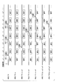
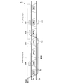
- FIG. 2 is a first diagram illustrating the function of the interval adjusting unit according to the first embodiment of the present invention.
- Vehicles 201 to 203 shown in FIG. 2 are vehicles that travel while stopping on the track 3 in the order of stations H1, H2,..., H7,.
- the vehicles 201 to 20n also stop at stations (stations H8, H9, H10,...) That are not shown in FIG.
- stations H8, H9, H10, etc that are not shown in FIG.
- the time from when each vehicle 201 to 203 leaves one station until it stops at the next station is uniformly “ ⁇ ”.
- the interval adjusting unit 104 specifies the target station (for example, the station H10 (not shown in FIG. 2)) based on the predetermined congestion information, the station H1 to the station H9 that are the stations behind the target station H10 at a predetermined timing.
- Each waiting time ⁇ 1 to ⁇ 9 is set.
- the interval adjusting unit 104 sets a longer standby time for a station closer to the reference station (target station H10). More specifically, it is set so that ⁇ 1 ⁇ 2 ⁇ 3 ⁇ . However, the interval adjusting unit 104 sets the smallest waiting time ⁇ 1 so that it does not fall below the minimum time Tmin that passengers can safely get on and off.
- the departure determination unit 102 sets the standby times ⁇ 1 to ⁇ 9 for all the vehicles 201, 202, and 203 traveling in the section. Based on this, the departure times at the stations H1 to H9 are adjusted.
- the operation process of the vehicles 201 to 203 based on the standby times ⁇ 1 to ⁇ 9 set by the interval adjusting unit 104 will be described with reference to FIG. First, it is assumed that the vehicle 201 leaves the station H1, the vehicle 202 leaves the station H3, and the vehicle 203 leaves the station H5 at the same time (time: T0).
- the vehicle 201 stops at the station H2, the vehicle 202 stops at the station H4, and the vehicle 203 stops at the station H6 (time: T0 + ⁇ ).
- the vehicle 201 waits at the station H2 for the waiting time ⁇ 2, it departs from the station H2 (time: T0 + ⁇ + ⁇ 2).
- the vehicle 202 waits for the waiting time ⁇ 4 (> ⁇ 2) at the station H4 and then leaves the station H4 (time: T0 + ⁇ + ⁇ 4).
- the vehicle 203 waits for the waiting time ⁇ 6 (> ⁇ 4) at the station H6, it departs from the station H6 (time: T0 + ⁇ + ⁇ 6). Since the standby time at each station is set as ⁇ 2 ⁇ 4 ⁇ 6, the vehicle interval between the vehicles 201 to 203 at this time is narrow.
- the vehicle 201 waits at the station H3 for the waiting time ⁇ 3, and then leaves the station H3 (time: T0 + 2 ⁇ + ⁇ 2 + ⁇ 3). Thereafter, the vehicle 202 waits for the waiting time ⁇ 5 (> ⁇ 3) at the station H5, and then departs from the station H5 (time: T0 + 2 ⁇ + ⁇ 4 + ⁇ 5). At this time, the distance between the vehicle 201 and the vehicle 202 is further narrowed. In addition, the vehicle 203 has not left the station H7, and the distance between the vehicle 202 and the vehicle 203 is narrow. As described above, the interval adjusting unit 104 sets the standby times ⁇ 1 to ⁇ 9 at the stations H1 to H9, so that the vehicles 201 to 203 gradually become closer to each other as the operation progresses.
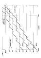
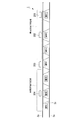
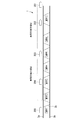
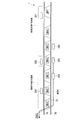
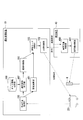
- FIG. 3 is a second diagram illustrating the function of the interval adjusting unit according to the first embodiment of the present invention.
- the horizontal axis indicates the elapsed time from the time T0
- the vertical axis indicates the positions (stations and stations) where the vehicles 201 to 203 exist.
- FIG. 3 shows that, for example, at time T0, the vehicle 201 leaves the station H1, the vehicle 202 leaves the station H3, and the vehicle 203 leaves the station H5, and each arrives at the next stop at time T0 + ⁇ . ing.
- the vehicle 201 travels at the stations H2 to H7 while waiting for the standby times ⁇ 2 to ⁇ 7 set for the stations.
- the vehicles 202 and 203 travel while waiting for the standby time set in each station (vehicle overcrowding operation).
- the inter-vehicle distances of the vehicles 201, 202, and 203 gradually decrease from time T0 to time T1.
- a state where the vehicles 203, 202, 201 are densely packed (vehicle overcrowded state) at the target station H10 and the stations H9, H8 behind the target station H10 is completed.
- the operation management apparatus 10 switches the operation of each vehicle 201 to 203 from the vehicle overcrowding operation to the congestion elimination operation. Specifically, the vehicles 201 to 203 operate so as to depart and arrive at the target station H10 at the shortest time interval (FIG. 3). In this way, at the target station H10 where the number of passengers is increasing, the vehicles 201 to 203 arrive and depart one after another, and the congestion at the target station H10 can be eliminated.
- the interval adjustment unit 104 appropriately sets the vehicle overcrowding operation start time (time T0) and the values of the standby times ⁇ j as follows based on the congestion information obtained in advance.
- the interval adjusting unit 104 sets the waiting time ⁇ j so that the congestion occurrence time estimated based on the congestion information matches the time when the density of the presence of the vehicles 201 to 20n increases. Specifically, using FIG. 3, the interval adjusting unit 104 detects in advance that the target station H10 is congested at time T1 based on the congestion information obtained in advance (the interval adjusting unit 104 generates congestion). Time is estimated as time T1). Therefore, the interval adjustment unit 104 back-calculates the vehicle overcrowding operation start time T0 and the waiting times ⁇ 0 to ⁇ 9 so that the vehicle overcrowding state is completed at the target station H10 at the time T1 at which congestion is estimated to occur. To set. In this way, the vehicle overcrowding state can be formed in advance in accordance with the time (congestion occurrence time) T1 at which congestion was predicted in advance, so that it is possible to respond quickly to a sudden increase in passengers. Can do.
- the interval adjustment unit 104 determines that there is enough time before the time T1 at which congestion is expected, for example, based on the congestion information obtained in advance, the interval adjustment unit 104 sets the time from the time T0 to the time T1 to be long.
- the standby times ⁇ 0 to ⁇ 9 are set so that the vehicle overcrowding state is gradually formed over time. That is, the interval adjusting unit 104 sets the time T0 and the standby times ⁇ 0 to ⁇ 9 so that the operation schedule does not change suddenly even when the operation based on the normal time schedule is switched to the operation based on the vehicle overcrowding operation.
- the vehicle traffic system 1 by this embodiment can keep the influence on the passenger who is going to board based on a normal diagram to the minimum.
- the interval adjusting unit 104 sets the time from time T0 to time T1 to be short, and sets each waiting time ⁇ 0 to ⁇ 9 so that the vehicle overcrowded state is quickly formed. Set. In this case, the corresponding standby times ⁇ 0 to ⁇ 9 are set to close the vehicle intervals in a short time.
- a vehicle overcrowded state can be quickly formed even when there is no time margin in this way, and therefore when the event schedule (for example, the end time of the event) is suddenly changed Even so, it can respond flexibly.
- the event schedule for example, the end time of the event
- the interval adjustment unit 104 sets the standby time ⁇ j based on the number of passengers estimated at the reference station (target station Hm) from the congestion information obtained in advance. More specifically, with reference to FIG. 3, the interval adjusting unit 104 sets the waiting times ⁇ 1 to ⁇ 9 so that the vehicles 201 to 203 arrive and depart one after another at the target station H10 at each time ⁇ when the operation is switched to the congestion elimination operation. Has been.
- the interval adjusting unit 104 sets the values of the waiting times ⁇ 1 to ⁇ 9 so that the time interval departs and arrives at 1.2 ⁇ intervals or 1.5 ⁇ intervals, for example. Set.
- the interval adjusting unit 104 sets the standby times ⁇ 1 to ⁇ 9 so as to increase more gradually from ⁇ 1 to ⁇ 9.
- the interval adjusting unit 104 waits for arrival and departure at intervals of 0.8 ⁇ or 0.5 ⁇ so that the time interval becomes shorter, for example.
- the interval adjusting unit 104 sets the standby times ⁇ 1 to ⁇ 9 so as to increase more steeply from ⁇ 1 to ⁇ 9.
- the interval adjusting unit 104 first determines the current positions of the vehicles 201 to 203 based on the “position information” of the vehicles 201 to 203 acquired via the vehicle position acquisition unit 100. To grasp.
- the distance from the current position of each of the vehicles 201 to 203 to the target station Hm is calculated.
- the position of the vehicle 201 in the initial state is farther from the target station Hm than the state shown in FIGS.
- the interval adjusting unit 104 performs a process of correcting the standby time ⁇ j at each station Hj for the vehicle 201.
- the interval adjustment unit 104 has a predetermined coefficient p () that decreases inversely as the distance L1 increases. 0 ⁇ p ⁇ 1) is multiplied by each waiting time ⁇ j.
- the standby time ⁇ j that the vehicle 201 should wait at each stop station Hj is set smaller. Then, the vehicle 201 can reach the place where it should be in an overcrowded state at time T1, regardless of the position at the time of starting the overcrowded operation.
- the stations H1 to H10 are all installed at equal intervals, and the vehicles 201 to 203 travel at the same speed between the stations.
- the time from the departure to the next station is “ ⁇ ”
- the actual operation of the vehicle traffic system 1 is not limited to such a mode. That is, in the vehicle traffic system 1, the stations Hj may be installed at different intervals for each station, and the travel times between the stations may be different.
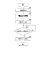
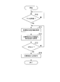
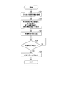
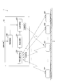
- FIG. 4 is a flowchart showing a process flow of the operation management apparatus according to the first embodiment of the present invention.
- the operation management apparatus 10 according to the present embodiment executes a process flow (FIG. 4) described below using the vehicle position acquisition unit 100, the interval adjustment unit 104, and the departure determination unit 102 described above.
- the interval adjustment unit 104 acquires congestion information based on the judgment of an administrator who has obtained predetermined event information in advance (step S31).
- the congestion information is information indicating an expected number of passengers, an estimated congestion occurrence time, a station where the congestion occurs, and the like.
- the vehicle position acquisition unit 100 acquires position information indicating the position where the specific target vehicle 20i exists (step S32).
- the vehicle position acquisition unit 100 receives and acquires position information indicating the position of the host vehicle from the target vehicle 20i.
- the interval adjustment unit 104 sets the time T0 for starting the vehicle overcrowding operation and the standby time ⁇ j for each station Hj based on the congestion information acquired in step S31 and the position information acquired in step s32. (Step S33).
- the interval adjusting unit 104 sets the start time T0 and the basic standby time ⁇ j ′ for each stop station Hj so as to gradually increase as the target station Hm is approached. Then, the interval adjusting unit 104 performs correction according to the position information of each of the vehicles 201 to 20n (multiplying the basic standby time ⁇ j ′ by the coefficient p), and stops the vehicles 201 to 20n. The waiting time ⁇ j for each station Hj is calculated. Then, based on the standby time ⁇ j set in step S33, the departure determination unit 102 executes a process of waiting for the standby time ⁇ j at the stop station Hj of the target vehicle 20i.
- the departure determination unit 102 determines whether or not the elapsed time after the target vehicle 20i stops at the station Hj is equal to or longer than the standby time ⁇ j (step S34), and the elapsed time is less than the standby time ⁇ j. If (NO in step S34), step S34 is repeated to suspend transmission of the departure instruction for target vehicle 20i. When departure time is equal to or longer than standby time ⁇ j (YES in step S34), departure determination unit 102 transmits a departure instruction to target vehicle 20i (step S35).
- the operation management apparatus 10 executes the processing flow from step S32 to step S35 for each of the vehicles 201 to 20n. Moreover, the operation management apparatus 10 repeats the process flow of step S34 whenever it stops at the stop station Hj with respect to the one target vehicle 20i.
- the operation management apparatus 10 executes the above processing flow (FIG. 4), so that the density of the presence of the vehicles 201 to 20n at the congestion occurrence station (station Hm) increases at the congestion occurrence time (time T1). A state is formed. Further, the density of the presence of the vehicles 201 to 20n at this time is set so that the balance of receipt is matched to the expected number of passengers.
- the density of provision of the transport service by a vehicle can be changed flexibly at a desired time and a desired station.
- the interval adjusting unit 104 has been described as setting so that the standby time ⁇ j gradually increases as the station is closer to the target station Hm.
- the vehicle traffic system 1 according to the present embodiment is It is not limited to such a process.
- the interval adjusting unit 104 may appropriately set the standby time ⁇ j at each station Hj in accordance with the original characteristics of the vehicle traffic system 1. For example, in the example shown in FIG. 3, when the number of passengers is constantly large at a specific station (for example, the station H6), the standby time ⁇ 6 based on the vehicle overcrowding operation is set to be smaller than the standby times ⁇ 1 to ⁇ 5 at the station H6. May be.
- the interval adjusting unit 104 may set another waiting time ⁇ j so that a vehicle overcrowded state is formed at the target station H10 after such an exceptional response.
- r1, r2,... are values of 1 or more. In this case, the interval adjustment unit 104 sets r1 ⁇ r2 ⁇ . By doing in this way, the space
- the interval adjusting unit 104 forms a vehicle overcrowded state by setting the standby time ⁇ j at the station Hj to gradually increase as the station is closer to the target station Hm.
- the vehicle traffic system 1 is not limited to such processing.
- the interval adjusting unit 104 may gradually reduce the traveling speed between the stations as the target station Hm is approached, thereby forming a vehicle overcrowded state at the target station Hm at a desired time. Good.
- FIG. 5 is a diagram showing a functional configuration of the vehicle traffic system according to the second embodiment of the present invention.
- the same functional configuration as that of the vehicle traffic system 1 (FIG. 1) according to the first embodiment is denoted by the same reference numeral and the description thereof is omitted. Omitted.
- the vehicle traffic system 1 does not include the operation management device 10 that is the ground facility in the first embodiment.
- Each of the vehicles 201 to 20n includes the vehicle position acquisition unit 100, the interval adjustment unit 104, and the departure determination unit 102 included in the operation management apparatus 10 according to the first embodiment (see FIG. 5 shows the functional configuration of only the vehicle 202 for convenience, but each of the vehicles 201 to 20n actually has the same functional configuration as the vehicle 202).
- each of the vehicles 201 to 20n can autonomously perform the vehicle overcrowding operation while communicating with the other vehicles 201 to 20n.
- the interval adjusting unit 104 of each of the vehicles 201 to 20n acquires the same congestion information from the predetermined information source (event operator or the like) described above (FIG. 4, step S31).
- the congestion information includes a station where the congestion is estimated (target station Hm) and a time when congestion is estimated (congestion occurrence time T1).
- the vehicle position acquisition unit 100 of each of the vehicles 201 to 20n acquires position information indicating the position where the host vehicle is present (FIG. 4, step S32).
- the vehicle position acquisition unit 100 acquires the current position of the host vehicle based on the number of rotations of the tire and information received from the position detection device, and also through other communication means with other vehicles.
- the position information about the vehicle is acquired.
- the interval adjusting unit 104 for each of the vehicles 201 to 20n starts the vehicle overcrowding operation based on the congestion information acquired in step S31 and the position information for each of the vehicles 201 to 20n acquired in step s32.
- the waiting time ⁇ j for each time T0 and each station Hj is set (FIG. 4, step S33).
- the interval adjusting unit 104 sets the start time T0 and the basic standby time ⁇ j ′ for each stop station Hj so as to gradually increase as the target station Hm is approached. Then, the interval adjusting unit 104 performs correction according to the position information of the own vehicle (multiplying the basic waiting time ⁇ j ′ by the coefficient p), and the waiting time for each stopping station Hj for the own vehicle. ⁇ j is calculated. Based on the standby time ⁇ j set in step S33, the departure determination unit 102 executes a process of waiting for the standby time ⁇ j at the stop station Hj of the host vehicle.
- the departure determination unit 102 determines whether or not the elapsed time after the host vehicle stops at the station Hj is equal to or longer than the standby time ⁇ j (FIG. 4, step S34), and the elapsed time is the standby time. If it is less than ⁇ j (NO in step S34 in FIG. 4), step S34 is repeated to hold the departure instruction of the host vehicle. When departure time becomes equal to or longer than standby time ⁇ j (YES in step S34 in FIG. 4), departure determination unit 102 transmits a departure instruction to the host vehicle (FIG. 4, step S35).
- each of the vehicles 201 to 20n can autonomously execute the vehicle overcrowding operation based on the determined standby time ⁇ j. Therefore, it is not necessary to operate the ground equipment (operation management apparatus 10) that centrally manages the entire operation of the vehicles 201 to 20n, and operation management processing can be distributed. If the operation management process is decentralized in this way, even if any of the operation management systems (in the case of the present embodiment, the vehicles 201 to 20n) malfunctions, the vehicle traffic system 1 Therefore, the reliability of the entire vehicle traffic system 1 can be improved.
- the vehicle traffic system 1 may further include a passenger guidance information system (PIS) as ground equipment.
- PIS passenger guidance information system
- a conventional PIS displays a scheduled arrival time of a vehicle on a screen provided at a station based on a predetermined diagram.
- the PIS receives the identification information, the position information, the route information, and the waiting time ⁇ j at each station from the operation management device 10 (each of the vehicles 201 to 20n in the second embodiment).
- the estimated arrival time for each station of the target vehicle 20i is calculated, and the estimated arrival time is displayed on a display screen installed at each station.
- the identification information of the target vehicle 20i may be a unique ID (IDentification) number or the like that can identify the target vehicle 20i.
- the PIS according to the present embodiment can easily calculate the time required for at least the next stop station from the traveling speed of the target vehicle 20i if the position information and route information can be grasped. Can be estimated.
- vehicle traffic system 1 may be further realized by the following embodiment.
- FIG. 6 is a diagram showing a functional configuration of the vehicle traffic system according to the third embodiment of the present invention.
- reference numeral 1 denotes a vehicle traffic system.
- the vehicle traffic system 1 includes an operation management device 10 and a plurality of vehicles 201, 202,..., 20 n that travel along a track 3 (n is an integer of 2 or more). ).
- the operation management apparatus 10 is called a ground facility, and is an apparatus that controls the operation of a plurality of vehicles 201, 202,.
- the operation management apparatus 10 according to the present embodiment is a functional unit that transmits a departure instruction to each of the vehicles 201, 202,..., 20n based on the determination of the departure determination unit 102 described later.
- the operation management apparatus 10 transmits a departure instruction to each of the vehicles 201 to 20n using a wireless communication unit or the like.
- Each of the vehicles 201 to 20n operates based on a departure instruction received from the operation management device 10.
- the vehicles 201, 202, ..., 20n are trains that travel along the track 3 (track).
- a safety device interlocking device
- a traffic light controls a traffic light
- a plurality of stations are provided along the track 3 according to the traffic light. Travel while arriving and arriving (not shown)
- the track 3 is provided with a predetermined position detection device (not shown) at regular intervals, and each of the vehicles 201 to 20n communicates with the position detection device so that the position of the own vehicle on the track 3 can be determined. You can recognize whether you are driving. To explain this function more specifically, each of the vehicles 201 to 20n has its own route database.
- Each of the vehicles 201 to 20n has a function of calculating the travel distance by measuring the tire rotation speed of the host vehicle and grasping the current position of the host vehicle.
- the current position that is grasped from the tire rotation speed due to tire slip or the like may deviate from the actual position.
- the vehicles 201 to 20n correct the deviation while comparing with the position detection device on the ground, so that it is possible to accurately grasp which position on the track 3 the host vehicle is traveling.
- the vehicle traffic system 1 enables individual vehicles based on the operation of the operation management apparatus 10 to be described below when a specific vehicle is delayed and the provision of the transport service becomes uneven.
- the time interval between them has a function of equalizing more quickly.
- the operation management apparatus 10 includes a vehicle position acquisition unit 100, a density calculation unit 101, and a departure determination unit 102.
- the vehicle position acquisition unit 100 is a functional unit that acquires the positions of a plurality of vehicles 201 to 20n existing on the track 3. As described above, each of the vehicles 201 to 20n communicates with a position detection device (not shown) provided on the track 3 to recognize which position the host vehicle is traveling on the track 3. Can do. Each of the vehicles 201 to 20n sequentially transmits “position information” indicating the traveling position of the own vehicle to the operation management apparatus 10 by wireless communication. The vehicle position acquisition unit 100 of the operation management apparatus 10 receives the position information of each of the vehicles 201 to 20n, and acquires the position of the vehicles 201 to 20n. In another embodiment, each of the vehicles 201 to 20n may transmit the position information to the operation management apparatus 10 by wired communication.
- the density calculation unit 101 is a functional unit that calculates the density of a plurality of vehicles 201 to 20n traveling within a predetermined range on the track 3. Specifically, the density calculation unit 101 acquires the number of vehicles traveling within a predetermined range based on the positions of the vehicles 201 to 20n acquired by the vehicle position acquisition unit 100. The density calculation unit 101 stores the number of vehicles as “density” of vehicles traveling within the predetermined range. Specific functions of the density calculation unit 101 will be described later.
- the departure determination unit 102 is based on one or both of “front density Df” and “rear density Dr” of a predetermined target vehicle 20i (i is an integer satisfying 1 ⁇ i ⁇ n, the same applies hereinafter).
- “adjusting the departure time” specifically means that the departure time is adjusted by changing the time at which the departure instruction is transmitted to the target vehicle 20i.
- the front density Df is the density of a vehicle that travels within a predetermined range in front of the target vehicle 20i in the traveling direction.
- the rear density Dr is the density of a vehicle that travels within a predetermined range behind the target vehicle 20i in the traveling direction.
- the departure determination unit 102 suspends transmission of a departure instruction for the target vehicle 20i until a predetermined condition based on one or both of “front density Df” and “rear density Dr” is satisfied. Perform the process. Then, the departure determination unit 102 performs a process of transmitting a departure instruction at a timing when the predetermined condition is satisfied. The target vehicle 20i departs from the stop station at the timing of receiving the departure instruction (more precisely, after satisfying other requirements for departure). In another embodiment, instead of the above-described aspect, the departure determination unit 102 continues to transmit a predetermined “departure hold instruction” while the predetermined condition is not satisfied, and the predetermined condition is satisfied.
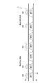
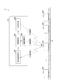
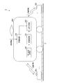
- FIG. 7 is a diagram illustrating the functions of the density calculation unit and the departure determination unit according to the third embodiment of the present invention.
- 7 are vehicles that travel on the first track 3a from the left side to the right side of the page.
- the vehicle 205 is a vehicle that travels from the right side to the left side on the second track 3b, which is a track different from the first track 3a.
- Each of the vehicles 201 to 205 travels in the traveling direction while arriving at and departing from each station shown in FIG.
- a plurality of branches 3c are provided between the first track 3a and the second track 3b, and each of the vehicles 201 to 205 is connected to the first track 3a and the second track 3b via the branch 3c. In some cases, the route is traversed.
- the density calculation unit 101 calculates “front density Df” and “rear density Dr” for each of the vehicles 201 to 20n.
- the density calculation unit 101 is a vehicle that travels within a range from a position immediately in front of the specific target vehicle 20i to the front kf station in the travel direction (kf is an integer of 1 or more).
- the number of vehicles 201 to 20n traveling in the range from the position immediately behind the target vehicle 20i to the rear in the driving direction to the kr station in the driving direction (kr is an integer of 1 or more) is obtained,
- the range from the position closest to the front in the traveling direction of the target vehicle 20i to the front kf station in the traveling direction is referred to as a “vehicle 20i front region”.
- a range from the position immediately behind the traveling direction of the target vehicle 20i to the rear kr station in the traveling direction is referred to as a “vehicle 20i rear region”.
- the target vehicle 20 i is the vehicle 203
- the front density Df and the rear density Dr are obtained.
- the vehicle 203 is stopped at the station H4.
- the area in front of the vehicle 203 is a range determined by a section from the position immediately in front of the host vehicle to the station H7 (FIG. 7).
- the rear region of the vehicle 203 is a range defined by a section from the position closest to the rear in the traveling direction of the host vehicle to the station H3 (FIG. 7).
- the vehicle 203 front area and the vehicle 203 rear area move following the traveling of the vehicle 203.
- the vehicle 203 front area is three stations ahead of the traveling direction from the station H5 (station H6 to station H8 (station H8 is not shown)), and the vehicle 203 rear area is There are 3 stations (station H2 to station H4) behind the station H5 in the direction of travel.
- the density calculation unit 101 calculates the forward density Df as “1/3”.
- the density calculation unit 101 calculates the rear density Dr as “1/3”. Note that when the density calculation unit 101 calculates the forward density Df, only the vehicles 201 to 20n traveling ahead of the route on which the vehicle 203 is scheduled to travel are considered. Therefore, in the example shown in FIG. 7, for calculating the forward density Df of the vehicle 203, the vehicle 205 traveling on a route (second track 3 b) different from the route on which the vehicle 203 intends to travel (second track 3 a) Not considered. In calculating the rear density Dr, other vehicles 201 to 20n traveling on a route (second track 3b) different from the route traveled by the vehicle 203 (first track 3a) are not considered.
- the departure determination unit 102 adjusts the departure time of the target vehicle 20i at the stop station based on the front density Df and the rear density Dr of the target vehicle 20i. Specifically, when the front-rear density difference ⁇ D, which is a value obtained by subtracting the rear density Dr from the front density Df, exceeds a predetermined density difference threshold value ⁇ ( ⁇ is a value of 0 or more) ( ⁇ D> ⁇ ), the departure determination is made.
- ⁇ D which is a value obtained by subtracting the rear density Dr from the front density Df
- the unit 102 suspends the transmission of the departure instruction to the target vehicle 20i until the condition ( ⁇ D ⁇ ⁇ ) that the front-rear density difference ⁇ D is equal to or less than the density difference threshold ⁇ is satisfied, and delays the departure time of the target vehicle 20i.
- the departure determination unit 102 sets ⁇ D> ⁇ as a condition for suspending transmission of a departure instruction to the target vehicle 20 i, and also sets ⁇ D ⁇ ⁇ as a condition for transmitting a departure instruction to the target vehicle 20 i.
- the departure determination unit 102 sets ⁇ D> ⁇ as a condition for suspending transmission of a departure instruction to the target vehicle 20 i, and sets a threshold ⁇ that is different from ⁇ as a condition for transmitting a departure instruction for the target vehicle 20 i. It is also possible to use ⁇ D ⁇ ⁇ ( ⁇ ). By doing in this way, since the period when a departure instruction is suspended is set longer, the frequency of performing adjustment can be reduced.
- FIG. 8 is a flowchart showing a process flow of the operation management apparatus according to the third embodiment of the present invention.
- the operation management apparatus 10 according to the present embodiment executes a processing flow (FIG. 8) described below using the vehicle position acquisition unit 100, the density calculation unit 101, and the departure determination unit 102 described above. Note that the processing flow of FIG. 8 shows the processing flow until the departure instruction is transmitted for the target vehicle 20i stopped at a predetermined station.
- a minimum stop time Tmin which is a time at which each of the vehicles 201 to 20n should stop at a minimum at each stop station, is defined in advance in order to secure a time for passengers to get on or get off. Yes.
- the departure determination unit 102 of the operation management apparatus 10 first determines whether the minimum stop time Tmin has elapsed since the target vehicle 20i arrives at the stop station and receives the notification (step S10). If the minimum stop time Tmin has not elapsed ("NO" in step S10), the process does not proceed to the next step until the minimum stop time Tmin has elapsed.
- the vehicle position acquisition unit 100 of the operation management apparatus 10 obtains the position information of each vehicle 201 to 20n traveling on the track 3 from each vehicle 201 to 20n (step S11).
- each of the vehicles 201 to 20n communicates with its own vehicle's tire rotational speed and the like, and with a position detection device (not shown) provided on the track 3 at regular intervals, so that the vehicle's own vehicle accurate Position information indicating the position can be acquired.
- the position information is, for example, information indicated by kilometers on the track 3.
- each of the vehicles 201 to 20n acquires the position (about kilometer) where the position detection device is installed on the track 3 through communication with the position detection device, and further, the progress from the timing of the communication.
- the position of the host vehicle (about kilometer) is uniquely determined based on time, traveling speed, and the like.
- the means by which the vehicle position acquisition unit 100 acquires the position information of each of the vehicles 201 to 20n is not limited to the above-described aspect.
- the position of each of the vehicles 201 to 20n may be acquired from predetermined coordinate information received by each of the vehicles 201 to 20n from a satellite based on GPS (Global Positioning System).
- the density calculation unit 101 calculates the front density Df and the rear density Dr for the target vehicle 20i based on the position information of each of the vehicles 201 to 20n acquired in step S11 (step S12).
- the departure determination unit 102 calculates the front-rear density difference ⁇ D based on the front density Df and the rear density Dr calculated in step S12, and further determines whether the front-rear density difference ⁇ D is equal to or lower than the density difference threshold ⁇ . Determination is made (step S13).
- step S13 when the front-rear density difference ⁇ D does not satisfy the condition of being equal to or lower than the density difference threshold ⁇ (“NO” in step S13), the process returns to step S11 to acquire the position information again, and the front density Df, Processing for calculating the rear density Dr is performed.
- the condition that the front-rear density difference ⁇ D is equal to or smaller than the density difference threshold ⁇ (“YES” in step S13)
- the departure determination unit 102 immediately transmits a departure instruction to the target vehicle 20i (step S14). .
- the operation management device 10 suspends the departure of the target vehicle 20i when the front-rear density difference ⁇ D is greater than the density difference threshold ⁇ by executing the above-described processing flow, and the front-rear density difference ⁇ D is greater than the density difference threshold ⁇ .
- the process of transmitting a departure instruction to the target vehicle 20i when the value becomes smaller is realized.
- the departure determination unit 102 of the operation management apparatus 10 first determines whether or not the minimum stop time Tmin has elapsed in step S10 and detects that the minimum stop time Tmin has elapsed. Thereafter, departure determination (step S11 to step S13) is performed by determining the front density Df, the rear density Dr, and the front-rear density difference ⁇ D.
- departure determination is performed by determining the front density Df, the rear density Dr, and the front-rear density difference ⁇ D.
- the processing order is not limited.
- the operation management apparatus 10 may determine whether or not the minimum stop time Tmin has elapsed (step S10) after determining the front-rear density difference ⁇ D or simultaneously with the determination of the front-rear density difference ⁇ D. It may be performed in parallel.
- the operation management apparatus 10 first performs steps S11, S12, and step S13, and repeats this processing if the determination of the front-to-back density difference ⁇ D is NO in step S13. And when it becomes YES at Step S13, it is judged (Step S10) whether the minimum stop time Tmin has passed after that. Furthermore, when it becomes NO here, Step S11, You may perform the process which performs S12 and S13. By doing so, the process of comparing the front-rear density (steps S11 to S13) can proceed without waiting for the minimum stop time Tmin, so that the time required for the process itself can be included in the waiting time of Tmin. It is possible to eliminate delays in command transmission.
- FIGS. 9A and 9B are first and second diagrams for explaining the effects of the vehicle traffic system according to the third embodiment of the present invention.
- Each of the vehicles 201 to 204 shown in FIGS. 9A and 9B is a vehicle that travels from the left side to the right side of the first track 3a.
- 10A and 10B are third and fourth diagrams for explaining the effect of the vehicle traffic system according to the third embodiment of the present invention.
- Each of the vehicles 201 to 205 shown in FIGS. 10A and 10B is a vehicle that travels on the first track 3a from the left side to the right side of the page, as in FIGS. 9A and 9B.
- the operation management device 10 of the vehicle traffic system 1 is configured so that the vehicles 201 to 20n are equally spaced based on the processing of the functional units of the vehicle position acquisition unit 100, the density calculation unit 101, and the departure determination unit 102 described above.
- the operation management that operates is performed.
- FIG. 9A shows a state where in the vehicle traffic system 1, some trouble has occurred in the vehicle (not shown) traveling forward in the traveling direction of the vehicle 201 traveling on the first track 3a, and the departure time is delayed. As shown in FIG. 9A, due to the delay of the departure time, the vehicle interval between the vehicle 201 and the vehicle 202 is shorter than normal. Here, attention is paid to the vehicle 203 shown in FIG. 9A.
- the density calculation unit 101 Based on the position information acquired via the vehicle position acquisition unit 100, the density calculation unit 101 detects that two vehicles of the vehicle 201 and the vehicle 202 exist in the vehicle 203 front area.
- the density calculation unit 101 detects that one vehicle 204 is present in the rear region of the vehicle 203 based on the acquired position information. Then, the density calculation unit 101 calculates the front density Df for the vehicle 203 as “2/3” and the rear density Dr as “1/3”.
- the vehicle 203 receives the departure instruction from the departure determination unit 102 and departs from the stop station H4.
- the operation management device 10 when the operation of the vehicles 201 to 20n becomes uneven due to a vehicle trouble or the like (FIG. 9A), the operation management device 10 performs the operation management as described above.
- the vehicle interval can be made uniform quickly.
- the vehicle 203 is directed from the station H4 to the station H5 in accordance with a set schedule even when the front vehicle interval is close as shown in FIG. 9A. To leave.
- the vehicles 201 to 203 become overcrowded (overcrowded), which promotes non-uniformity in providing transport services.
- the density calculation unit 101 has the density of the other vehicles 201 and 202 within the range of the vehicle 203 front area. Detect state. If the area is “dense”, the departure determination unit 102 immediately suspends the departure of the vehicle 203 even if the next station is vacant and falls into an overcrowded state (overcrowded state). Can be avoided in advance. Further, when there is a delay in front of the vehicle 203, according to the conventional operation management device, the departure time of the vehicle 203 is adjusted based on the vehicle distance from the vehicle 202 closest to the front. As shown in FIG.
- the vehicle transportation system 1 according to the vehicle 201 is determined to leave the vehicle 203 as a direct trigger when the vehicle 201 leaves the station H7.
- the departure determination unit 102 immediately transmits a departure instruction to the vehicle 203 regardless of the vehicle distance from the vehicle 202 that travels most recently. .
- the vehicle interval between the vehicle 203 and the vehicle 202 is small, in that case, the vehicle interval between the vehicle 202 and the vehicle 201 has rather room, and the prediction that the vehicle 202 should proceed without delay. Is implied.
- the vehicle traffic system 1 when the vehicle traffic system 1 according to the present embodiment detects that the vehicle is in a “dense” state in the front area of the target vehicle 20i, the vehicle transportation system 1 falls into a more dense state (overcrowded state) by immediately delaying departure. To avoid it. Further, if it is determined that the “dense” state has been removed in the front area of the vehicle 20i, the target vehicle is not waited for the distance between the vehicles 201 to 20n traveling immediately in front of the target vehicle 20i to increase. Depart 20i. As described above, the vehicle traffic system 1 according to the present embodiment is based on the density of the vehicle in the region ahead of the vehicle 20i with respect to the target vehicle 20i, from the stage before each of the vehicles 201 to 20n falls into an overcrowded state. By determining the stoppage, it is possible to speed up the time until the transportation service is provided in a non-uniform manner.
- FIG. 10A shows a state where two vehicles 201 and 202 are traveling in the vehicle 203 front area and two vehicles 204 and 205 are traveling in the rear area of the vehicle 203 in the vehicle traffic system 1.
- the departure time of the vehicle 205 (stopped at the station H1) located behind the vehicle 203 is delayed.
- the vehicles 201 to 205 are in a state as shown in FIG. 10B.
- the vehicle 203 detects the sparse / dense state of the other vehicles 204 and 205 within the range of the rear region of the vehicle 203 and becomes “sparse” in that region. If it is, the departure is immediately suspended, and it is possible to prevent the situation from falling into a less sparse state (depopulation state). Further, when there is a delay behind the vehicle 203, according to the conventional operation management device, the departure time of the vehicle 203 is adjusted based on the vehicle distance from the vehicle 204 nearest to the rear. 10B, if the vehicle 205 arrives at the station H2 after the state shown in FIG. 10B, the departure of the vehicle 203 is determined regardless of the vehicle distance from the vehicle 204.
- the vehicle traffic system 1 is based on the density of the vehicle in the rear region of the vehicle 20i with respect to the target vehicle 20i, from the stage before each vehicle 201 to 20n falls into a sparse state. By determining the stoppage, it is possible to speed up the time until the transportation service is provided in a non-uniform manner.
- the preceding vehicle 201 has left the front region of the vehicle 203 before the vehicle 205 belongs to the rear region of the vehicle 203 as a result of the vehicle 203 being stopped.
- the departure determination unit 102 since the front-rear density difference ⁇ D satisfies the condition ( ⁇ D ⁇ ⁇ ) that is equal to or less than the density difference threshold ⁇ , the departure determination unit 102 immediately transmits a departure instruction to the vehicle 203 (at this time, the minimum stop time Tmin is ).
- the departure determination unit 102 transmits a departure instruction to the vehicle 203 even when the preceding vehicle 201 leaves the front region of the vehicle 203 before the vehicle 205 belongs to the rear region of the vehicle 203.
- the front density Df and the rear density Dr are controlled to be as uniform as possible.
- the departure determination unit 102 determines the transmission timing of the departure instruction based on the information of both the front density Df and the rear density Dr, thereby more effectively suppressing the provision of the transportation service. can do.
- the vehicles 201 to 20n when the transportation service provided by the vehicles becomes uneven, the vehicles 201 to 20n can be connected to the vehicles 201 to 20n from the previous stage when the vehicle is overcrowded or depopulated. Since the departure time is adjusted, the effect can be obtained more quickly. Moreover, according to this vehicle traffic system 1, since the departure time is adjusted so that each vehicle does not fall into a congested state or a depopulated state, even when some of the vehicles become difficult to operate due to a failure or the like, for example. The other vehicles can stand by while maintaining the vehicle interval so as not to be overcrowded and sparsely in accordance with the stoppage of the failed vehicle.
- the values of kf and kr may be different.
- the density calculation unit 101 calculates the front density Df and the rear density Dr by the number of vehicles existing in the range of the kf station in the traveling direction or the rear kr station at the position where the target vehicle 20i exists.
- the density calculation unit 101 according to another embodiment of the present invention is not limited to this mode.
- the density calculation unit 101 according to another embodiment calculates, for example, the front density Df and the rear density Dr by the number of vehicles existing within a predetermined route distance (for example, 10 km ahead and 10 km behind the target vehicle 20 i) on the track 3. Also good.
- the density calculation unit 101 uses the number of vehicles existing in a predetermined route section (for example, the front 10 section and the rear 10 section of the target vehicle 20i) divided at regular intervals on the track 3, and the front density Df and the rear density Dr. May be calculated. In this way, even when the intervals between the stations installed on the track 3 are extremely uneven, the departure time is appropriately adjusted based on the actual route distance or the vehicle density in the route section. It can be performed. Further, the density calculation unit 101 calculates, for example, an inter-vehicle distance L with respect to the third vehicle counting from the nearest front (rear) in the traveling direction of the target vehicle 20i, and the target vehicle 20i is calculated based on the inter-vehicle distance L.
- the front density Df (rear density Dr) may be calculated.
- the departure determination unit 102 may adjust the departure time of the target vehicle 20i at the stop station based on the magnitude relationship between the forward density Df and a predetermined forward density threshold value Dfth (Dfth is a value of 0 or more). More specifically, when the forward density Df is higher than a predetermined forward density threshold value Dfth (Df> Dfth), the departure determination unit 102 transmits a departure instruction until the forward density Df becomes equal to or less than the forward density threshold value Dfth. And the departure time at the stop station of the target vehicle 20i may be delayed.
- Dfth is a value of 0 or more
- the departure determination unit 102 advances the transmission time of the departure instruction until the forward density Df becomes equal to or greater than the forward density threshold Dfth.
- the departure time of the target vehicle 20i at the stop station may be advanced.
- the departure determination unit 102 may adjust the departure time of the target vehicle 20i at the stop station based on the magnitude relationship between the rear density Dr and a predetermined rear density threshold Drth (Drth is a value of 0 or more). . More specifically, when the rear density Dr is lower than a predetermined rear density threshold Drth (Dr ⁇ Drth), the departure determination unit 102 transmits a departure instruction until the rear density Dr becomes equal to or higher than the rear density threshold Drth. And the departure time at the stop station of the target vehicle 20i may be delayed. Conversely, when the rear density Dr is higher than the predetermined rear density threshold Drth (Dr> Drth), the departure determination unit 102 advances the transmission time of the departure instruction until the rear density Dr becomes equal to or lower than the rear density threshold Drth. Thus, the departure time of the target vehicle 20i at the stop station may be advanced.
- Drth is a value of 0 or more
- the operation management apparatus 10 has an effect of equalizing the vehicle intervals of the respective vehicles 201 to 20n by adjusting the departure time of the target vehicle 20i at the stop station, but the operation management according to the present embodiment.
- the apparatus 10 is not limited to this process in making the vehicle intervals of the vehicles 201 to 20n uniform.
- the operation management apparatus 10 instead of adjusting the departure time of the stop station, the operation management apparatus 10 lowers the traveling speed of the target vehicle 20i or stops between the stations in order to equalize the vehicle intervals of the vehicles 201 to 20n. May be.
- a vehicle traffic system according to a fourth embodiment of the present invention will be described. Since the functional configuration of the vehicle traffic system 1 according to the fourth embodiment is the same as that of the vehicle traffic system 1 (FIG. 6) according to the third embodiment, the description thereof is omitted.
- the vehicle traffic system 1 according to the fourth embodiment is different from the third embodiment in the processing flow executed by the operation management device 10.
- the operation management apparatus 10 according to the third embodiment has a front-rear density difference ⁇ D that is equal to or less than a predetermined density difference threshold value ⁇ ( ⁇ D ⁇ ⁇ ) based on information on both the front density Df and the rear density Dr. ),
- ⁇ D ⁇ ⁇ a predetermined density difference threshold value
- the process flow of transmitting a departure instruction to the target vehicle 20i is executed.
- the departure determination unit 102 according to the fourth embodiment uses the value of the front-to-back density difference ⁇ D calculated from the front density Df and the rear density Dr to determine the time during which the target vehicle 20i should wait at the stop station (waiting time). Tw) is calculated, and a departure instruction is transmitted when the waiting time Tw has elapsed.
- the departure determination unit 102 calculates the waiting time Tw as shown in Expression (1) based on, for example, the front-rear density difference ⁇ D.
- the value q is a predetermined coefficient having a value of 0 or more.
- the standby time Tw of the target vehicle 20i increases as the front-rear density difference ⁇ D for the target vehicle 20i increases, that is, as the front is “dense” compared to the rear.
- the waiting time Tw is set small when the density of the other vehicles 201 to 20n is small before and after the target vehicle 20i, and the waiting time is set accordingly when the density of the other vehicles 201 to 20n is large. Tw is set large, and the effect of eliminating the non-uniformity of operation of the vehicles 201 to 20n can be obtained.
- the coefficient q may be selected from an optimum constant obtained from an empirical rule, a result of operation simulation, or the like.
- the coefficient q may be a variable based on, for example, the “front vehicle distance Lf” and the “rear vehicle distance Lr” of the target vehicle 20i.
- the “front inter-vehicle distance Lf” is an inter-vehicle distance between the target vehicle 20i and the other vehicles 201 to 20n that are traveling immediately in front of the traveling direction.
- the “rear inter-vehicle distance Lr” is the inter-vehicle distance between the target vehicle 20i and the other vehicles 201 to 20n that are traveling immediately behind in the traveling direction.
- the departure determination unit 102 may calculate the coefficient q as shown in Expression (2) based on the front inter-vehicle distance Lf and the rear inter-vehicle distance Lr.
- the value q ′ is a predetermined coefficient having a value of 0 or more.
- the value of the coefficient q increases as the front inter-vehicle distance Lf becomes larger than the rear inter-vehicle distance Lr, and the standby time Tw tends to increase.
- the value of the coefficient q becomes small and the standby time Tw tends to decrease.
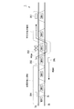
- FIG. 11 is a flowchart figure which shows the processing flow of the operation management apparatus by 4th embodiment of this invention.
- the operation management apparatus 10 according to the present embodiment executes a processing flow (FIG. 11) described below.
- the processing flow of FIG. 11 shows the processing flow until the departure instruction is transmitted for the target vehicle 20i stopped at a predetermined station.
- the vehicle position acquisition unit 100 of the operation management apparatus 10 acquires position information of each of the vehicles 201 to 20n traveling on the track 3 (step S21).
- the density calculation unit 101 calculates the front density Df and the rear density Dr for the target vehicle 20i based on the position information of each of the vehicles 201 to 20n acquired in step S21. Further, the density calculation unit 101 acquires the front inter-vehicle distance Lf and the rear inter-vehicle distance Lr of the target vehicle 20i (step S22).
- the departure determination unit 102 calculates the front-rear density difference ⁇ D based on the front density Df and the rear density Dr calculated in step S22, and the coefficient q (formula (2)) based on the front inter-vehicle distance Lf and the rear inter-vehicle distance Lr. ) Is calculated.
- the departure determination unit 102 calculates the standby time Tw based on the equation (1) (step S23).
- the departure determination unit 102 determines that the start determination unit 102 determines the minimum stop time Tmin. Is set as the waiting time Tw.
- the departure determination unit 102 first determines whether or not the waiting time Tw has elapsed since the target vehicle 20i arrived at the stop station (step S24). If the standby time Tw has not elapsed ("NO” in step S24), the process does not proceed to the next step until the standby time Tw has elapsed. When standby time Tw has elapsed (“YES” in step S24), departure determination unit 102 transmits a departure instruction to target vehicle 20i (step S25).
- the operation management device 10 executes the processing flow described above, and when the standby time Tw obtained by a predetermined calculation formula based on the front-rear density difference ⁇ D, the front inter-vehicle distance Lf, and the rear inter-vehicle distance Lr has elapsed, The process of transmitting a departure instruction to 20i is realized.
- the operation management apparatus 10 acquires the position information of the vehicles 201 to 20n (step S21) and calculates various parameters (Df, Dr, Lf, Lr) (step S22). ), The system waits for the waiting time Tw calculated according to these. Therefore, the operation management apparatus 10 according to the present embodiment acquires the position information of the vehicles 201 to 20n by the vehicle position acquisition unit 100 and the various parameters (Df, The process of calculating Dr, Lf, Lr) need only be performed once. Therefore, since the position information acquisition and the calculation of various parameters (Df, Dr) are not repeatedly performed as in the operation management device 10 according to the third embodiment (FIG. 8), the operation management is performed more than in the third embodiment. The processing load on the apparatus 10 can be reduced.
- FIG. 12 is a diagram for explaining the effect of the vehicle traffic system according to the fourth embodiment of the present invention.
- each of the vehicles 201 to 204 shown in FIG. 12 is a vehicle that travels from the left side to the right side of the first track 3a.
- the effect of performing the operation management in consideration of the front inter-vehicle distance Lf and the rear inter-vehicle distance Lr will be described.
- the vehicle 203 stopped at the station H4 there are two vehicles 201 and 202 in the vehicle 203 front area. These vehicle intervals are shorter than usual.
- the vehicle 202 has a wider vehicle distance from the vehicle 203, and the front inter-vehicle distance Lf, which is the distance between the vehicle 203 and the nearest vehicle 202 in front of the traveling direction, is relatively large. ing.
- only one vehicle 204 is present in the rear region of the vehicle 203. Also, as shown in FIG.
- the vehicle 204 has a narrower vehicle distance from the vehicle 203, and the rear inter-vehicle distance Lr, which is the distance between the vehicle 203 and the nearest vehicle 204 behind the traveling direction, is the front inter-vehicle distance Lf. (Lf ⁇ Lr ⁇ 0).
- the departure determination unit 102 simply calculates the standby time Tw based only on the front density Df and the rear density Dr of the vehicle 203
- the front-rear density difference ⁇ D becomes a positive value in the state shown in FIG.
- the vehicle 203 is caused to wait for a predetermined waiting time Tw at the station H4 (formula (1)).
- Tw waiting time
- the front inter-vehicle distance Lf of the vehicle 203 is actually larger than the rear inter-vehicle distance Lr, and the vehicle 203 is rather in a state where the vehicle interval with the following vehicle 204 is small. If the standby time Tw is generated for the vehicle 203 in such a state, a more dense state (overcrowded state) may be promoted behind the vehicle 203.
- the operation management apparatus 10 can select an appropriate operation even in a case where the vehicle distance between the vehicle and the nearest vehicle in the front in the traveling direction is wide although the forward density Df is high. it can.
- FIG. 13 is a diagram showing a functional configuration of a vehicle traffic system according to the fifth embodiment of the present invention.
- the same functional configuration as that of the vehicle traffic system 1 (FIG. 6) according to the third embodiment is denoted by the same reference numeral and the description thereof is omitted. Omitted.
- the operation management device 10 of the vehicle traffic system 1 is configured to further include a route determination unit 103 in addition to the functional configurations of the vehicle traffic system 1 according to the third embodiment.
- the route determination unit 103 is a functional unit that designates a travel route on the track 3 for each of the vehicles 201 to 20n.
- the route determination unit 103 transmits predetermined route information to each of the vehicles 201 to 20n according to the operation status.
- the vehicles 201 to 20n select the route specified in the route information and travel.
- the route determination unit 103 also outputs the same route information to the density calculation unit 101.
- the density calculation unit 101 that has input the route information transmitted to the predetermined target vehicle 20i sets the vehicle 20i front region and the vehicle 20i rear region based on the travel route specified by the route information. Then, the density calculation unit 101 calculates the front density Df based on the vehicle 20i front region set here and the rear region Dr based on the vehicle 20i rear region. In this way, when the travel route of the target vehicle 20i is changed by the route determination unit 103, the density calculation unit 101 determines the forward density Df and the target vehicle 20i based on the newly set travel route each time. The rear density Dr can be calculated.
- the vehicle position acquisition unit 100 has a function of acquiring the traveling directions of the plurality of vehicles 201 to 20n. Specifically, the vehicle position acquisition unit 100 first detects a change in the position of the vehicles 201 to 20n indicated by the position information received from each of the vehicles 201 to 20n. Further, the vehicle position acquisition unit 100 refers to the route information of each of the vehicles 201 to 20n from the route determination unit 103, and “up” the traveling direction of each of the vehicles 201 to 20n from the transition of the position of the vehicles 201 to 20n on the route. Or, it is determined as “down”.
- the means by which the vehicle position acquisition unit 100 acquires the traveling direction of each of the vehicles 201 to 20n is not limited to the above-described means, and any means can be used as long as the information on the traveling direction of the vehicles 201 to 20n can be obtained. It may be.
- FIGS. 14A and 14B are first and second diagrams illustrating the effects of the vehicle traffic system according to the fifth embodiment of the present invention.
- 14A and 14B are vehicles that travel on the first track 3a from the left side to the right side of the page.
- the vehicle 205 is a vehicle that travels from the right side to the left side on the second track 3b, which is a track different from the first track 3a.
- FIG. 14A With reference to FIG. 14A and FIG. 14B, the effect of performing operation management in consideration of route changes will be described.
- two vehicles a vehicle 201 stopped at the station H7 and a vehicle 202 stopped at the station H5 on the first track 3a, are ahead of the traveling direction of the vehicle 203 stopped at the station H4. Existing. Further, only one vehicle 204 is present behind the vehicle 203 in the traveling direction (the vehicle 203 rear region). Further, a vehicle 205 that travels in the direction opposite to the vehicle 203 on the second track 3b is stopped at the station H5 in the traveling direction of the vehicle 203.
- the route determination unit 103 transmits route information indicating a new route (route A) to the vehicle 203 in order to continue operation of the vehicle 203.
- the route determination unit 103 passes through the branch 3c between the station H4 and the station H5 and enters the second track 3b, and passes through the branch 3c between the station H5 and the station H6.
- the route is set so as to pass through and return to the first track 3a (route A). That is, the route determination unit 103 transmits to the vehicle 203 route information indicating a route (route A) that bypasses the vehicle 202 that cannot be operated due to a failure.
- the route determination unit 103 also outputs route information indicating the same route (route A) to the density calculation unit 101.
- route A route information indicating the same route
- the density calculation unit 101 detects that the route of the vehicle 203 has been changed. Then, the density calculation unit 101 resets the vehicle 203 front area for the newly set route for the vehicle 203.
- the front area of the vehicle 203 is reset according to the newly set route A. That is, as shown in FIG. 14A, the vehicle 203 front area passes through the branch 3c between the station H4 and the station H5 and enters the second track 3b, and passes through the branch 3c between the station H5 and the station H6. Thus, it is a range of three stations ahead in the traveling direction along the route returning to the first track 3a.
- the density calculation unit 101 calculates a front density Df based on the newly set vehicle 203 front area.
- the vehicle 203 front area reset here includes the vehicle 201 stopped at the station H7 and the vehicle 205 traveling on the second track 3b. Therefore, the density calculation unit 101 calculates the forward density Df as “2/3”. In this case, since the rear density Dr is “1/3”, the vehicle 203 stands by at the station H4.
- the route determination unit 103 sequentially outputs the route information indicating the changed route to the density calculation unit 101, so that the density calculation unit 101 can obtain information on the newly selected route.
- the forward density Df can be calculated. Accordingly, the departure times of the vehicles 201 to 20n are adjusted so that the vehicle intervals are uniform based on the newly calculated forward density Df and backward density Dr, even when a route change is instructed. .
- the vehicle traffic system 1 may further have the following functions. Specifically, the vehicle position acquisition unit 100 acquires the plurality of vehicles 201 to 20n position information and also acquires the traveling direction information indicating the traveling direction of each of the vehicles 201 to 20n.
- the density calculation unit 101 inputs the traveling direction information, and whether there is a vehicle traveling in the direction opposite to the traveling direction of the target vehicle 20i in front of the traveling direction on the track 3 on which the target vehicle 20i travels. Determine.
- the operation management device 10 determines that there is a vehicle traveling in the direction opposite to the traveling direction of the target vehicle 20i, a predetermined correction process is performed to increase the forward density Df for the target vehicle 20i. 14A and 14B, the target vehicle 20i is the vehicle 203, and the “vehicle traveling in the direction opposite to the traveling direction of the target vehicle 20i” is the vehicle 205.
- the vehicle 203 travels along the route B while the vehicle 203 is stopped at the station H4, and as a result of deviating from the vehicle 203 front area, the front density Df of the vehicle 203 is obtained.
- the vehicle 203 can leave the station H4.
- the front density Df of the vehicle 203 decreases, and the vehicle 203 Will be able to leave station H4.
- the vehicle 203 does not leave the station H4 unless the rear density Dr is 4/3 or more.
- the vehicle traffic system 1 enables a dynamic route change according to a change in operation status due to an unexpected vehicle failure or the like, and provides a safer transport service. Can do.
- FIGS. 15A and 15B are third and fourth diagrams illustrating the effects of the vehicle traffic system according to the fifth embodiment of the present invention.
- 15A and 15B are vehicles that travel on the first track 3a from the left side to the right side of the page.
- the vehicles 205 and 206 are vehicles that travel from the right side to the left side of the second track 3b, which is a track different from the first track 3a.
- the vehicle traffic system 1 it is possible to cope with the following situation.
- the vehicle 203 stopped at the station H4 in the vehicle 203 front area, the vehicle 201 stopped at the station H7 and the vehicle 202 stopped at the station H5 on the first track 3a.
- orbit 3b in the opposite direction to the vehicle 203 are stopping at the station H4 and the station H6, respectively.
- the vehicle 202 is a vehicle that travels in the same direction as the vehicle 203 on the first track 3a.
- the route determination unit 103 causes the vehicle 202 to move to the vehicle base (Depot (FIGS. 15A and 15B). It is assumed that the route (route C) that is pulled up to)) is reset. Then, since there is a vehicle 202 traveling in the reverse direction in the vehicle 203 front area at the stage of FIG. 15A, the vehicle 203 performs a correction process (for example, the vehicle 202) for increasing the front density Df when calculating the front density Df. 1), the vehicle 203 stands by at the station H4 until the vehicle 202 is out of the vehicle 203 front area. Similarly, the vehicle 204 stands by at the station H2 until the vehicle 202 moves out of the vehicle 204 front area (not shown).
- a correction process for example, the vehicle 202
- the vehicle 202 travels to the station H4 along the second track 3b. Then, the departure determination unit 102 detects that the vehicle 202 is out of the front region of the vehicle 203 and the front density Df is reduced by the density calculation unit 101, and transmits a departure instruction to the vehicle 203.
- the vehicles 205 and 206 traveling on the second track 3b travel to the station H5 and the station H3, respectively. However, as shown in FIG. 15B, the vehicle 202 enters the second track 3b so as to interrupt between the vehicle 205 and the vehicle 206. Then, the forward density Df of the vehicle 205 suddenly increases. As a result, the vehicle 205 waits at the station H5 until the forward density Df decreases.
- the vehicle traffic system 1 When a vehicle that is suddenly returned to Depot occurs, it has been necessary to re-create a diagram for all of the vehicles in the past. However, according to the vehicle traffic system 1 according to the present embodiment, the vehicle returned to Depot and even its route are designated. Then, the vehicle interval between the vehicle and other vehicles is automatically adjusted. Therefore, the effect of reducing labor when returning the vehicle to Depot can be obtained.
- the vehicle traffic system 1 according to the third to fifth embodiments described above has been described as a mode in which the single ground facility, that is, the operation management device 10 controls the operation of all the vehicles 201 to 20n.
- the vehicle traffic system 1 according to another embodiment of the invention is not limited to such a mode.
- the vehicle traffic system 1 according to the other embodiment may include a plurality of different operation management devices 10 as ground facilities.
- each of the operation management devices 10 assigned to each predetermined section of the track 3 may control the operations of the vehicles 201 to 20n traveling in the predetermined section.
- FIG. 16 is a diagram showing a functional configuration of a vehicle traffic system according to the sixth embodiment of the present invention.
- the same functional configuration as that of the vehicle traffic system 1 (FIG. 6) according to the third embodiment is denoted by the same reference numeral and the description thereof is omitted. Omitted.
- the vehicle traffic system 1 does not include the operation management device 10 which is the ground facility in the third to fifth embodiments.
- Each of the vehicles 201 to 20n includes the vehicle position acquisition unit 100, the density calculation unit 101, and the departure determination unit 102 that are included in the operation management apparatus 10 in the third to fifth embodiments. (For convenience, the functional configuration of only the vehicle 202 is shown in FIG. 16, but actually each of the vehicles 201 to 20n has the same functional configuration as the vehicle 202).
- each of the vehicles 201 to 20n can autonomously adjust the vehicle interval while communicating with the other vehicles 201 to 20n.
- the vehicle position acquisition units 100 of the vehicles 201 to 20n communicate with each other to acquire position information about the vehicles 201 to 20n (FIG. 8, step S11).
- the density calculation unit 101 provided in each of the vehicles 201 to 20n calculates the front density Df and the rear density Dr for the own vehicle based on the position information of the vehicles 201 to 20n (FIG. 8, step S12).
- the departure determination unit 102 provided in each of the vehicles 201 to 20n determines whether to leave the vehicle or to leave the departure based on the front density Df and the rear density Dr for the vehicle (FIG. 8, Steps S13 and S14).
- each of the vehicles 201 to 20n grasps the mutual positional relationship, and autonomously communicates with other vehicles based on the vehicle density in the front and rear. It becomes possible to operate while adjusting the interval. Therefore, it is not necessary to operate the ground equipment (operation management apparatus 10) that centrally manages the entire operation of the vehicles 201 to 20n, and operation management processing can be distributed. If the operation management process is decentralized in this way, even if any of the operation management systems (in the case of the present embodiment, the vehicles 201 to 20n) malfunctions, the vehicle traffic system 1 Therefore, the reliability of the entire vehicle traffic system 1 can be improved.
- Each of the vehicles 201 to 20n of the vehicle traffic system 1 according to the sixth embodiment of the present invention further has the function described in the fourth embodiment (operation control based on the front inter-vehicle distance Lf and the rear inter-vehicle distance Lr).
- the function described in the fifth embodiment (dynamic route change processing by the route determination unit 103) may be provided.
- the vehicle traffic system 1 may further include a passenger guidance information system (PIS) as ground equipment.
- PIS passenger guidance information system
- the conventional PIS displays the scheduled arrival time of the vehicle on a screen provided at the station based on a predetermined diagram, but in the case of the vehicle traffic system 1 according to the present embodiment, the operation may be performed without using the diagram. Therefore, based on only the diamond information, it is impossible to know which vehicle will arrive when.
- the PIS according to the present embodiment receives the identification information, the position information, and the route information of the target vehicle 20i from the operation management apparatus 10 (each of the vehicles 201 to 20n in the case of the sixth embodiment)
- the estimated arrival time for each station of the vehicle 20i is calculated, and the calculated estimated arrival time is displayed on a display screen installed at each station.
- the identification information of the target vehicle 20i may be a unique ID (IDentification) number or the like that can identify the target vehicle 20i.
- the PIS according to the present embodiment can easily calculate the time required for at least the next stop station from the traveling speed of the target vehicle 20i if the position information and route information can be grasped. Can be estimated.
- the PIS according to the present embodiment further calculates various parameters such as the front density Df, the rear density Dr, the front inter-vehicle distance Lf, the rear inter-vehicle distance Lr from the density calculation unit 101, and the target vehicle is based on these parameters.
- the estimated arrival time of 20i may be estimated.
- the PIS according to the present embodiment calculates the waiting time T of the target vehicle 20i obtained using the formulas (1) and (2), thereby estimating the estimated arrival time at each station. I do.
- the passenger of the vehicle traffic system 1 grasps the estimated arrival time of the vehicles 201 to 20n arriving at the station even when the vehicles 201 to 20n are not traveling based on the timetable. can do.
- the PIS receives each parameter from the density calculation unit 101 each time various parameters such as the front density Df and the rear density Dr for the target vehicle 20i change according to the operation status.
- a new estimated arrival time may be calculated.
- the vehicle traffic system 1 can provide passengers with a more accurate estimated arrival time in response to the operation status of each of the vehicles 201 to 20n dynamically.
- FIG. 17 is a diagram showing a functional configuration of the vehicle traffic system according to the seventh embodiment of the present invention.
- FIG. 18 is a figure which shows the function structure of the vehicle traffic system by 8th embodiment of this invention.
- the operation management device 10 according to the seventh embodiment of the present invention includes the function of the interval adjustment unit 104 according to the first embodiment described above and the function of the density calculation unit 101 according to the third embodiment. And the aspect provided with both may be sufficient.
- the departure determination unit 102 of the operation management apparatus 10 according to the present embodiment has both the function of the departure determination unit 102 according to the first embodiment and the function of the departure determination unit 102 according to the third embodiment. The aspect provided may be sufficient.
- the functions of the density calculation unit 101 and the departure determination unit 102 according to the third embodiment are valid.
- the functions of the interval adjustment unit 104 and the departure determination unit 102 according to the first embodiment may be invalidated.
- the functions of the density calculation unit 101 and the departure determination unit 102 according to the third embodiment may be invalidated.
- the vehicles 201 to 20n according to the eighth embodiment of the present invention have the functions of the interval adjusting unit 104 according to the second embodiment described above and the density calculating unit 101 according to the sixth embodiment. It is also possible to have an aspect having both functions.
- the departure determination unit 102 of the vehicles 201 to 20n according to the present embodiment performs both the function of the departure determination unit 102 according to the second embodiment and the function of the departure determination unit 102 according to the sixth embodiment. The aspect provided may be sufficient.
- the functions of the density calculation unit 101 and the departure determination unit 102 according to the sixth embodiment are valid.
- each of the vehicles 201 to 20n operates while appropriately selecting the vehicle interval equalizing function according to the function of the sixth embodiment and the vehicle density changing function according to the second embodiment. be able to.
- FIG. 19 is a diagram illustrating a functional configuration of a vehicle traffic system according to another embodiment.
- the operation management device 10 described in each of the above embodiments is simply a functional unit that transmits a departure instruction to each of the vehicles 201, 202,..., 20n based on the determination of the departure determination unit 102. .
- Each of the vehicles 201 to 20n is operated based on a departure instruction received from the operation management device 10.
- the operation management device 10 may further include an operation progress calculation unit 107, an operation mode determination unit 105, and a diagram information storage unit 106. .
- the operation progress calculation unit 107 compares the position information of each vehicle 201 to 20n acquired by the vehicle position acquisition unit 100 and the operation diagram information stored in the diagram information storage unit 106, and compares the actual information of each vehicle 201 to 20n. It is a function part which calculates progress information which shows progress of operation. Note that the earliest departure time predetermined for each vehicle / station is recorded in advance in the schedule information stored in the schedule information storage unit 106. The earliest departure time is the earliest time at which each vehicle should leave each station, which is determined based on the operation schedule.
- the route determination unit 103 can identify the route that each of the vehicles 201 to 20n should travel after by referring to the progress information calculated by the operation progress calculation unit 107.
- the operation mode determination unit 105 is a functional unit that sets the operation mode of each of the vehicles 201 to 20n based on the front-rear density difference ⁇ D (or the front density Df, the rear density Dr) calculated by the density calculation unit 101.
- the operation modes determined by the operation mode determination unit 105 include “normal operation mode”, “interval adjustment mode”, and “overcrowded operation mode”.
- the operation management device 10 performs operation control based on operation schedule information as usual.
- the route determination unit 103 determines whether or not the operation progress calculation unit 107 is operating on each of the vehicles 201 to 20n and then determines a predetermined route for the target vehicle 20i according to the result. select.
- the departure determination unit 102 transmits a departure instruction in accordance with the departure time (early departure time).
- the operation management device 10 performs operation control for adjusting the vehicle interval based on the front density Df and the rear density Dr described in the third to sixth embodiments.
- the operation management device 10 intentionally sets the congested state at the time T1 and the target station Hm based on the congestion information described in the first to second embodiments. The operation control to be formed is performed.
- the operation mode determination unit 105 performs operation control in the normal operation mode (that is, the target vehicle 20i leaves each station according to the operation diagram.
- the operation management device 10 shifts to operation control in the interval adjustment mode for adjusting the vehicle interval.
- the departure determination unit 102 adjusts the departure time of the target vehicle 20i based on the front density Df and the rear density Dr, when the operation control is shifted to the interval adjustment mode. At this time, the departure determination unit 102 adjusts the departure time of the target vehicle 20i in the interval adjustment mode so that the departure time of the target vehicle 20i is not earlier than the earliest departure time that is the time at which the target vehicle 20i should originally leave the station. May be. In this way, the operation management apparatus 10 can prevent the target vehicle 20i from leaving the station at a time earlier than the time when it should originally leave. It is possible to prevent you from falling behind.
- the operation mode determination unit 105 immediately switches to the congested operation mode at a timing when predetermined congestion information is input, and starts operation control for forming a congested state.
- the safety device 40 and the traffic light 6 are used. Processing may exist.
- a general operation management apparatus the progress of the operation of each vehicle with respect to a predetermined operation schedule is grasped by tracking all the vehicles and grasping their positions. And the said operation management apparatus transmits a course request
- the security device is an operation control device that controls the operation while ensuring the safety of each vehicle.
- the safety device determines whether or not the vehicle can be departed from the viewpoint of safety. If the security device permits departure, the security device turns the traffic light corresponding to the route blue and the vehicle can leave. If this traffic light remains red, the vehicle remains stopped.
- the process of displaying blue or red on the traffic light corresponding to the route of the security device 40 is expressed as permitting or not allowing the travel to the route.
- the departure determination unit 102 determines the security device for the route on which the target vehicle 20i specified by the route determination unit 103 should travel based on the route information of the track 3 before transmitting the departure instruction to the target vehicle 20i.
- a route request is transmitted to 40, and processing for obtaining permission to proceed is performed.
- the security device 40 includes a vehicle protection determination unit 400 and a traffic light control unit 401.
- the vehicle protection determination unit 400 may advance the target vehicle 20i to the route from the viewpoint of safety. Determine whether or not. Since the vehicle protection determination unit 400 is a known technology, its specific function will not be described.
- the vehicle protection determination unit 400 may be a target vehicle when there is another vehicle in its destination. The advancement of the target vehicle 20i is permitted after the other vehicle is no longer allowed on the spot.
- the route determination unit 103 specifies a route on which the target vehicle 20i is going to proceed based on the calculation result of the operation progress calculation unit 107. At this time, when a plurality of route candidates can be selected, the route determination unit 103 may output information indicating the route candidates and a predetermined priority order for each route to the departure determination unit 102. . In this case, the departure determination unit 102 may perform a process of transmitting a route request for each route candidate to the security device 40 in the given priority order.
- the traffic signal control unit 401 performs control to actually switch the traffic light 6 corresponding to the route to blue or red in accordance with permission or non-permission of progress to the route. It is a functional part to perform.
- the operation management device 10 may perform operation control based on the above-described embodiments in a situation where safety is ensured based on the control of the security device 40.
- the departure instruction according to the front density Df and the rear density Dr transmitted by the departure determination unit 102 in the interval adjustment mode is a condition that ensures safety based on the control of the security device 40. It is emitted after filling. Therefore, the vehicle traffic system 1 can exhibit each function in the above-described embodiments while ensuring high safety.
- the operation management apparatus 10 or the vehicles 201 to 20n have a computer system therein.
- Each process of the operation management device 10 or the vehicles 201 to 20n described above is stored in a computer-readable recording medium in the form of a program, and the program is read and executed by the computer. Is done.
- the computer-readable recording medium means a magnetic disk, a magneto-optical disk, a CD-ROM (Compact Disk Only Memory), a semiconductor memory, or the like.
- the computer program may be distributed to the computer via a communication line, and the computer that has received the distribution may execute the program.
- the density of provision of transportation services by vehicles can be flexibly changed at a desired time and a desired station.
Landscapes
- Engineering & Computer Science (AREA)
- Mechanical Engineering (AREA)
- Train Traffic Observation, Control, And Security (AREA)
- Management, Administration, Business Operations System, And Electronic Commerce (AREA)
- Traffic Control Systems (AREA)
Abstract
複数の車両(201~20n)の運行を管理する運行管理装置(10)は、複数の車両(201~20n)の位置を取得する車両位置取得部(100)と、混雑情報に基づいて、複数の車両(201~20n)の存在の密度を高める基準となる駅を特定し、当該基準となる駅の後方の駅に停車する複数の車両(201~20n)の、当該後方の駅ごとの待機時間を設定する間隔調整部(104)と、当該待機時間に基づいて、複数の車両(201~20n)の後方の駅ごとにおける出発時刻を調整する出発判断部(102)と、を備える。
Description
本発明は、軌道を走行する車両、その車両の運行を管理する運行管理装置、車両及び運行管理装置からなる車両交通システム、運行管理方法及びプログラムに関する。本願は、2013年5月30日に、日本に出願された特願2013-114554号に基づき優先権を主張し、その内容をここに援用する。
従来、所定の軌道(路線)に沿って走行する車両(列車等)による輸送サービスを提供する車両交通システムでは、予め規定されたダイヤ(時刻表)に基づいて各車両の運行が管理される。具体的には、いわゆる地上設備である運行管理装置が、車両ごとに定められた到着時刻、出発時刻等に基づいて各車両に指示を出し、当該各車両はその指示に従って運行する。このようなダイヤに基づく運行制御においては、運行の乱れ時、ダイヤを変更し、その変更後のダイヤに従って車両を運行することで、運行乱れの解消を図っている。このダイヤ変更は、合理性の確保を要する高度な作業であり、相応の労力と時間を要する。また、単に時間がかかるのみならず、ダイヤの変更作業を合理的に行うには多くの経験が必要であり、その経験の豊富さによっては、対応できる内容が限定されてしまう。特に新興国で鉄道が全く存在しないような都市では、この傾向が顕著になる。
一方、近年、情報伝達手段の発達が著しく、運行管理装置と車両、車両と車両、各々の間の情報伝達方法と設備の確立により、運行管理装置と車両の連携動作、若しくは、車両同士の連携動作が可能な環境が構築できるようになってきている。また、情報処理手段の高性能化が著しく、車両、地上設備、それぞれ個々の装置が、個々の裁量の範囲内で、自立した情報処理・制御動作が可能になってきている。
例えば、特許文献1に記載の列車運行制御方法によれば、ある他の車両の時間遅延が所定値以上であった場合に、当該他の車両と自車両との時間間隔を自律的に調整しながら、自車両の発車時刻を決定することを特徴としている。
ところで、特定のスタジアムや展示会場で開催されるコンサートや展示会など、非定期的なイベントが催される場合、そのイベント会場の最寄り駅など、特定の駅に局所的かつ一時的に利用者が集中することがある。このような場合に通常のダイヤ通りに車両を運行しようとすると、一時的に増加した利用者(乗客)に対応しきれず、乗客が駅のホームに収まりきれない事態となって混乱を招く場合がある。したがって、車両交通システムの運営者は、このようなイベントについての情報を予め入手しておき、そのイベントの推定動員数などから想定される駅の利用者数(乗客数)、そのイベントの開催時刻、終了時刻、1車両当たりの最大搭乗可能人数、及び、路線情報等に基づいて特別ダイヤを作成する。この特別ダイヤは、具体的には、集中が予想される特定の駅、及びその時刻で車両の存在の密度が“密”となるように作成される。このようにすれば、非定期的なイベントに応じて一時的に利用者が集中する場合であっても、その増加乗客数に適応して運行間隔を密にした輸送サービスを提供することができる。
しかしながら、上述したような特別ダイヤによる対応では、特別ダイヤの作成のために労力及び時間を費やす必要が生じる。また、イベントの終了時刻に変更があった場合などの想定外の事態が発生したときに、迅速な対応ができない可能性がある。
一方、特許文献1に記載の列車運行制御方法によると、複数の車両各々がそれぞれの前後を走行する車両との車両間隔を調整することで、車両交通システム全体として車両間隔が均一化される作用が得られる。しかしながら特許文献1に記載の列車運行制御方法は、上述したような非定期的なイベント等が催される場合において、特定の駅及び特定の日時に局所的に増加する乗客数に合わせて車両間隔を“密”にする、という調整を可能とする技術とはなっていない。
また、特許文献1に記載の列車運行制御方法によると、現に駅に存在する乗客(待合客)の人数(混雑度)を検知し、これに応じて、車両ごとの乗客数が均一化されるように車間距離を調整する手法を用いている。しかしながら、駅における待合客数は流動的であり、時々刻々と変化するものである。したがって、現時点における待合客数を検知してから、運転間隔の調整を開始するのでは対応が遅くなり、待合客数に応じた輸送サービスの提供を適切に行うことができない場合がある。
また、車両がダイヤに基づかない運転をした場合、どのプラットフォームにどの車両がいつ到達するのかという情報が駅の表示スクリーンに表示されない。
本発明は、上述の問題を解決することのできる運行管理装置、運行管理方法、車両、車両交通システム及びプログラムを提供する。
本発明の第1の態様によれば、運行管理装置は、軌道に沿って走行する複数の車両の運行を管理する運行管理装置であって、前記軌道上に存在する前記複数の車両の位置を取得する車両位置取得部と、所定の混雑情報に基づいて、前記複数の車両の存在の密度を高める基準となる駅を特定し、当該基準となる駅の後方の駅に停車する前記複数の車両の、当該後方の駅ごとの待機時間を設定する間隔調整部と、前記待機時間に基づいて、前記複数の車両の前記後方の駅ごとにおける出発時刻を調整する出発判断部と、を備える。
本発明の第2の態様によれば、上記態様の運行管理装置において、前記間隔調整部が、前記基準となる駅に近い駅ほど、その駅の前記待機時間を長く設定する。
本発明の第3の態様によれば、上記態様の運行管理装置において、前記間隔調整部が、前記基準となる駅において推定される乗客数に基づいて前記待機時間を設定する。
本発明の第4の態様によれば、上記態様の運行管理装置において、前記間隔調整部が、前記混雑情報に基づいて推定される混雑発生時刻と、前記車両の存在の密度が高まる時刻と、が一致するように前記待機時間を設定する。
本発明の第5の態様によれば、上記態様の運行管理装置において、前記間隔調整部が、前記混雑情報として、予定された集客イベントについての事前集客情報、集客箇所から駅までの通路に設置され、当該通路の利用客の人数及びその流れを検知する検知手段から取得される検知情報、または、他の交通網に関する到着予定時刻、到着予定人数を示す情報のうちの何れか一つまたは複数を取得する。
本発明の第6の態様によれば、車両交通システムは、上記態様の運行管理装置と、前記運行管理装置から所定の対象車両の識別情報、位置情報、及び経路情報を受信して、前記対象車両の各駅についての到着予定時刻を算出し、当該算出された到着予定時刻を、各駅に設置されている表示スクリーンへ表示させる旅客案内情報システムと、を備える。
本発明の第7の態様によれば、車両は、軌道に沿って走行する車両であって、前記軌道上における自車両の位置を取得する車両位置取得部と、所定の混雑情報に基づいて、前記軌道上を走行する複数の車両の存在の密度を高める基準となる駅を特定し、当該基準となる駅の後方の駅に停車する自車両の、当該後方の駅ごとの待機時間を設定する間隔調整部と、前記待機時間に基づいて、前記自車両の前記後方の駅ごとにおける出発時刻を調整する出発判断部と、を備える。
本発明の第8の態様によれば、運行管理方法は、軌道に沿って走行する複数の車両の運行を管理する運行管理方法であって、前記軌道上に存在する前記複数の車両の位置を取得し、所定の混雑情報に基づいて、前記複数の車両の存在の密度を高める基準となる駅を特定し、当該基準となる駅の後方の駅に停車する前記複数の車両の、当該後方の駅ごとの待機時間を設定し、前記待機時間に基づいて、前記複数の車両の前記後方の駅ごとにおける出発時刻を調整する。
本発明の第9の態様によれば、プログラムは、軌道に沿って走行する複数の車両の運行を管理する運行管理装置のコンピュータを、前記軌道上に存在する前記複数の車両の位置を取得する車両位置取得手段、所定の混雑情報に基づいて、前記複数の車両の存在の密度を高める基準となる駅を特定し、当該基準となる駅の後方の駅に停車する前記複数の車両の、当該後方の駅ごとの待機時間を設定する間隔調整手段、前記待機時間に基づいて、前記複数の車両の前記後方の駅ごとにおける出発時刻を調整する出発判断手段、として機能させる。
上述した運行管理装置、運行管理方法、車両、車両交通システム及びプログラムによれば、所望の時刻及び所望の駅において、車両による輸送サービスの提供の密度を柔軟に変化させることができる。
<第一の実施形態>
以下、本発明の第一の実施形態による車両交通システムを、図面を参照して説明する。
図1は、本発明の第一の実施形態による車両交通システムの機能構成を示す図である。この図において、符号1は車両交通システムである。
以下、本発明の第一の実施形態による車両交通システムを、図面を参照して説明する。
図1は、本発明の第一の実施形態による車両交通システムの機能構成を示す図である。この図において、符号1は車両交通システムである。
(車両交通システム全体の構成)
まず、車両交通システム1全体の構成について説明する。
図1に示すように、本実施形態による車両交通システム1は、運行管理装置10、及び、軌道3に沿って走行する複数の車両201、202、・・・、20n(nは2以上の整数)からなる。運行管理装置10は、地上設備と呼ばれるもので、複数の車両201、202、・・・、20nの運行を制御する装置である。
本実施形態に係る運行管理装置10は、後述する出発判断部102の判断に基づいて、車両201、202、・・・、20nそれぞれに出発指示を送信する機能部である。運行管理装置10は、無線通信手段等を用いて各車両201~20nに出発指示を送信する。各車両201~20nは、運行管理装置10から受信する出発指示に基づいて運行する。
なお実際の車両の運行にあたっては、保安装置(連動装置)や信号機に基づく運行制御がさらに加わるが、本実施形態の説明の簡略化のため、ここでは単に、運行管理装置10に基づいて車両201~20nの運行制御が成されるものとして説明する(保安装置等を用いた場合については、図19を用いて後述する。)
車両201、202、・・・、20nは、所定の軌道3(線路)に沿って走行する列車である。車両201~20nは、運行管理装置10から受信する運行の指示に従って、軌道3に沿って複数設けられた駅(図1には不図示)に発着しながら走行する。なお軌道3には一定間隔ごとに所定の位置検知装置(不図示)が設けられており、各車両201~20nは、当該位置検知装置と通信することで、自車両が軌道3上のどの位置を走行しているかを認識することができる。
この機能についてより具体的に説明すると、車両201~20nの各々は自ら路線データベースを備えている。そして車両201~20nの各々は、自車両のタイヤ回転数を測ることで走行距離を算出し、自車両の現在位置を把握する機能を有している。しかしこの場合、タイヤスリップなどに起因してタイヤ回転数から把握される現在位置が、実際の位置とずれる場合がある。車両201~20nは、地上におかれている位置検知装置と比較しながらずれを補正することで、自車両が軌道3上のどの位置を走行しているかを正確に把握する。
この機能についてより具体的に説明すると、車両201~20nの各々は自ら路線データベースを備えている。そして車両201~20nの各々は、自車両のタイヤ回転数を測ることで走行距離を算出し、自車両の現在位置を把握する機能を有している。しかしこの場合、タイヤスリップなどに起因してタイヤ回転数から把握される現在位置が、実際の位置とずれる場合がある。車両201~20nは、地上におかれている位置検知装置と比較しながらずれを補正することで、自車両が軌道3上のどの位置を走行しているかを正確に把握する。
ここで、通常の車両交通システムの場合、利用者数(乗客数)と、車両ごとの乗車可能量と、に基づいて、その受給バランスが最適となるようにダイヤが決定される。一般的には、平日ダイヤ、休日ダイヤの二通りがあれば日常の輸送サービスの提供に支障をきたすことはない。しかしながら、例えばあるイベント会場で、コンサートや展示会などの特殊なイベントが催されると、その日のみ特異的に乗客数の増加が見込まれる場合がある。このような場合に、日常通りのダイヤで運行するのでは乗客を輸送しきれない問題が発生する。そこで、本実施形態による車両交通システム1は、イベントの内容などから推定される情報(後述する「混雑情報」)を取得して、予めその混雑の状況に適合できるように、特定の駅において車両間隔が“密”となる状態を意図的に作り出す機能を有している。
(運行管理装置の構成)
次に、運行管理装置10の構成について説明する。
図1に示すように、本実施形態による運行管理装置10は、車両位置取得部100と、間隔調整部104と、出発判断部102とを備えている。
次に、運行管理装置10の構成について説明する。
図1に示すように、本実施形態による運行管理装置10は、車両位置取得部100と、間隔調整部104と、出発判断部102とを備えている。
車両位置取得部100は、軌道3上に存在する複数の車両201~20nの位置を取得する機能部である。各車両201~20nは、上述したように、軌道3上に設けられた位置検知装置(不図示)と通信することで、自車両が軌道3上のどの位置を走行しているかを認識することができる。そして車両201~20nの各々は、逐次自車両の走行位置を示す「位置情報」を無線通信により運行管理装置10に送信する。運行管理装置10の車両位置取得部100は、各車両201~20n各々の位置情報を受信して、車両201~20nの位置を取得する。なお、車両位置取得部100は、各車両の位置情報だけでなく、各車両の最大乗車可能人数を示す情報を取得してもよい。また、他の実施形態においては、車両201~20nの各々は、上記位置情報を有線通信により運行管理装置10に送信してもよい。
間隔調整部104は、所定の情報源から取得する「混雑情報」に基づいて、複数の車両201~20nの存在の密度を高める基準となる駅(目標駅Hm(mは2以上の整数))を特定し、当該目標駅Hmの後方の駅Hj(jは1以上m未満の整数)に停車する複数の車両201~20nの、当該後方の駅Hjごとの待機時間ωjを設定する。ここで「混雑情報」とは、具体的には、イベント(例えばコンサートや展示会)等が催されるイベント会場の立地条件(最寄り駅等)、並びに、予め推定される観客動員数、そして、当該イベントの開始時刻、終了時刻等の情報である。すなわち、現実に駅構内にて混雑が発生する前の段階において、その混雑が発生することを予測できる情報である。混雑情報の具体的な取得方法については後述する。
また、間隔調整部104は、さらに、現在走行中の車両の最大乗車可能人数と、路線情報に基づいて待機時間ωjを設定してもよい。
また、間隔調整部104は、さらに、現在走行中の車両の最大乗車可能人数と、路線情報に基づいて待機時間ωjを設定してもよい。
本実施形態による間隔調整部104は、この混雑情報に基づいて、まず目標駅Hmを特定する。目標駅Hmは、混雑が予測される駅、すなわちイベント会場の最寄り駅となる。そして間隔調整部104は、この目標駅Hmの手前において車両201~20nの存在の密度を高めるための処理を行う。なお「車両201~20nの存在の密度」とは、軌道3上の一定の範囲内における車両201~20nの車両数である。すなわち間隔調整部104が目標駅Hmの手前における一定範囲内で車両201~20nの車両数を増やす(存在の密度を高める)ことで、車両交通システム1は、目標駅Hmにて局所的・一時的に増加する乗客に対応することが可能となる。
間隔調整部104は、車両201~20nの存在の密度を高めるために、以下のような処理を行う。間隔調整部104は、当該目標駅Hmの後方の駅Hjに停車する複数の車両201~20nの、当該後方の駅Hjごとの待機時間ωjを設定する。待機時間ωjの具体的な設定方法については後述する。なお「目標駅Hmの後方の駅Hj」とは、車両201~20nが目標駅Hmに停車する前に停車する各駅を指している。ここで、車両201~20nが駅H1、H2、・・・、Hm-1、Hmの順番で停車するものとすると、この場合、目標駅Hmの後方の駅Hjとは駅H1、H2、・・・、Hm-1のことである。
出発判断部102は、駅Hjごとに設定された待機時間Tjに基づいて、複数の車両201~20nの後方の駅Hjごとにおける出発時刻を調整する機能部である。具体的には、出発判断部102は、対象車両20iが駅Hjに停車すると、その駅Hjについて設定された待機時間Tjだけ待機する処理を行い、待機時間Tjが経過したときに対象車両20iに駅Hjを出発する指示を送信する。
なお本実施形態に係る運行管理装置10の間隔調整部104は、所定の情報源から混雑情報を取得すると説明した。上述したように、所定の情報源とは、例えば集客イベントの開催主であって、混雑情報とは、当該開催主から事前に発信されるその集客イベントについての事前集客情報(イベントスケジュール、予想客数等)である。
また、混雑情報は、スタジアム等の施設である集客箇所から最寄り駅までの通路(緩衝帯という)に設置され、当該通路の利用客の人数及びその流れを検知する検知手段から取得される検知情報(例えば監視カメラより映し出される映像)であってもよい。車両交通システム1の管理者は混雑度予測部5である監視カメラをモニタリングすることで、最寄り駅(目標駅H10)に混雑が発生するまでの時刻を予め予測することができる。また、監視カメラからの映像ではなく、例えば、通路の所定箇所(ゲート等)に設けられた通過検知センサから取得される検知情報であってもよい。
さらに、車両交通システム1が、他の交通網と連絡している場合には、混雑情報とは、当該他の交通網に関する輸送媒体の到着予定時刻、到着予定人数を示す情報であってもよい。例えば、車両交通システム1が、空港ターミナルを結ぶ交通システムであった場合、航空機の離着陸スケジュールに合わせて車両交通システム1の需要が増減する。したがって、この場合の所定の情報源とは当該航空機の運営会社であり、混雑情報とは、その飛行機の離着陸スケジュールや乗客数(乗車率)となる。
(間隔調整部の機能)
図2は、本発明の第一の実施形態による間隔調整部の機能を説明する第一の図である。図2に示す車両201~203は、軌道3を紙面左側から右側に向かって駅H1、H2、・・・、H7、・・・の順に停車しながら走行する車両である。なお各車両201~20nは、図2には図示していない駅H7以降の駅(駅H8、H9、H10、・・・)にも停車する。また説明の便宜のため、各駅H1~H10は全て等間隔に設置されており、車両201~203は、各駅間を同一の速度で走行するものとする。また以下の説明においては、説明を簡単にするために、各車両201~203が一の駅を出発してから次の駅に停車するまでの時間を一律に“α”とする。
図2は、本発明の第一の実施形態による間隔調整部の機能を説明する第一の図である。図2に示す車両201~203は、軌道3を紙面左側から右側に向かって駅H1、H2、・・・、H7、・・・の順に停車しながら走行する車両である。なお各車両201~20nは、図2には図示していない駅H7以降の駅(駅H8、H9、H10、・・・)にも停車する。また説明の便宜のため、各駅H1~H10は全て等間隔に設置されており、車両201~203は、各駅間を同一の速度で走行するものとする。また以下の説明においては、説明を簡単にするために、各車両201~203が一の駅を出発してから次の駅に停車するまでの時間を一律に“α”とする。
以下、間隔調整部104の具体的な機能について、図2を参照しながら説明する。
間隔調整部104は、所定の混雑情報に基づいて目標駅(例えば駅H10(図2には不図示))を特定すると、所定のタイミングで目標駅H10の後方の駅である駅H1~駅H9ごとの待機時間ω1~ω9を設定する。ここで間隔調整部104は、基準となる駅(目標駅H10)に近い駅ほど、その駅の待機時間を長く設定する。より具体的には、ω1<ω2<ω3<・・・<ω9となるように設定する。ただし間隔調整部104は、最も小さい待機時間ω1が、乗客が安全に乗降車できる最低限の時間Tminを下回らないように設定する。
間隔調整部104は、所定の混雑情報に基づいて目標駅(例えば駅H10(図2には不図示))を特定すると、所定のタイミングで目標駅H10の後方の駅である駅H1~駅H9ごとの待機時間ω1~ω9を設定する。ここで間隔調整部104は、基準となる駅(目標駅H10)に近い駅ほど、その駅の待機時間を長く設定する。より具体的には、ω1<ω2<ω3<・・・<ω9となるように設定する。ただし間隔調整部104は、最も小さい待機時間ω1が、乗客が安全に乗降車できる最低限の時間Tminを下回らないように設定する。
間隔調整部104が、駅H1~駅H9ごとの待機時間ω1~ω9を設定すると、出発判断部102は、その区間を走行する車両201、202、203全てに対し、その待機時間ω1~ω9に基づいて、各駅H1~H9における出発時刻を調整する。以下、間隔調整部104によって設定された待機時間ω1~ω9に基づく車両201~203の運行プロセスを、図2を参照しながら説明する。
まず車両201が駅H1を、車両202が駅H3を、そして、車両203が駅H5を同時刻に出発したとする(時刻:T0)。次に、車両201は駅H2に、車両202は駅H4に、そして、車両203は駅H6に停車する(時刻:T0+α)。次に、車両201が駅H2で待機時間ω2だけ待機した後、駅H2を出発する(時刻:T0+α+ω2)。遅れて、車両202が駅H4で待機時間ω4(>ω2)だけ待機した後、駅H4を出発する(時刻:T0+α+ω4)。さらに遅れて、車両203が駅H6で待機時間ω6(>ω4)だけ待機した後、駅H6を出発する(時刻:T0+α+ω6)。各駅における待機時間がω2<ω4<ω6と設定されたことにより、この時点における車両201~203の車両間隔は狭くなっている。
まず車両201が駅H1を、車両202が駅H3を、そして、車両203が駅H5を同時刻に出発したとする(時刻:T0)。次に、車両201は駅H2に、車両202は駅H4に、そして、車両203は駅H6に停車する(時刻:T0+α)。次に、車両201が駅H2で待機時間ω2だけ待機した後、駅H2を出発する(時刻:T0+α+ω2)。遅れて、車両202が駅H4で待機時間ω4(>ω2)だけ待機した後、駅H4を出発する(時刻:T0+α+ω4)。さらに遅れて、車両203が駅H6で待機時間ω6(>ω4)だけ待機した後、駅H6を出発する(時刻:T0+α+ω6)。各駅における待機時間がω2<ω4<ω6と設定されたことにより、この時点における車両201~203の車両間隔は狭くなっている。
続いて、車両201は、駅H3で待機時間ω3だけ待機した後、駅H3を出発する(時刻:T0+2α+ω2+ω3)。その後、車両202が、駅H5で待機時間ω5(>ω3)だけ待機した後、駅H5を出発する(時刻:T0+2α+ω4+ω5)。この時点で、車両201と車両202の車両間隔はさらに狭まっている。また車両203も駅H7を出発しておらず、車両202と車両203の車両間隔も狭まっている。このように、間隔調整部104が、駅H1~H9における待機時間ω1~ω9を設定することで、車両201~車両203は、運行が進むにつれ徐々に互いの車両間隔が狭まっていく。
図3は、本発明の第一の実施形態による間隔調整部の機能を説明する第二の図である。図3に示すグラフは、横軸に時刻T0からの経過時間を、縦軸に各車両201~203の存在する位置(駅及び駅間)を示している。図3によれば、例えば時刻T0において、車両201が駅H1を、車両202が駅H3を、車両203が駅H5を出発し、時刻T0+αにおいてそれぞれが次の停車駅に到着することが示されている。
図3に示すように、車両201は、駅H2~H7において、それぞれに設定された待機時間ω2~ω7だけ待機しながら走行する。車両202、203も同様に、各駅に設定された待機時間だけ待機しながら走行する(車両過密化運転)。この車両過密化運転の結果、時刻T0から時刻T1にかけて、車両201、202、203の各々の車間距離は徐々に狭まっていく。そして図3に示すように、時刻T1において、目標駅H10及びその後方の駅H9、H8で車両203、202、201が密集する状態(車両過密化状態)が完成する。
車両過密化状態が完成すると、運行管理装置10は、各車両の201~203の運行を、車両過密化運転から混雑解消運転に切り替える。具体的には、車両201~203は、目標駅H10を最短の時間間隔で発着するように運行する(図3)。このようにすれば、乗客数が増加している目標駅H10において、車両201~203が次々と発着し、目標駅H10における混雑を解消することができる。
また間隔調整部104は、事前に得た混雑情報に基づいて、車両過密化運転開始時刻(時刻T0)及び各待機時間ωjの値を、以下のようにして適切に設定する。
間隔調整部104は、混雑情報に基づいて推定される混雑発生時刻と、車両201~20nの存在の密度が高まる時刻と、が一致するように待機時間ωjを設定する。図3を用いて具体的に説明すると、間隔調整部104は、事前に得た混雑情報により、予め時刻T1において目標駅H10が混雑することを検知している(間隔調整部104は、混雑発生時刻を時刻T1と推定する)。したがって間隔調整部104は、混雑が発生すると推定された時刻T1においてちょうど目標駅H10で車両過密化状態が完成するように、車両過密化運転の開始時刻T0及び各待機時間ω0~ω9を逆算して設定する。このようにすれば、予め混雑が予測されていた時刻(混雑発生時刻)T1に合わせて事前に車両過密化状態を形成することができるので、乗客の急激な増加に対して迅速に対応することができる。
また間隔調整部104は、例えば事前に得た混雑情報により、混雑が予想される時刻T1までに時間的余裕があると判断した場合は、時刻T0~時刻T1の時間を長く設定し、この長い時間をかけて徐々に車両過密状態が形成されていくように各待機時間ω0~ω9を設定する。すなわち間隔調整部104は、通常ダイヤに基づく運行から車両過密化運転に基づく運行に切り替えた際にも、運行スケジュールが急激に変化しないように時刻T0及び待機時間ω0~ω9設定する。このようにすることで、本実施形態による車両交通システム1は、通常ダイヤに基づいて乗車しようとする乗客への影響を最小限に留めることができる。一方、時間的余裕がないと判断した場合は、間隔調整部104は、時刻T0~時刻T1の時間を短く設定し、迅速に車両過密状態が形成されていくように各待機時間ω0~ω9を設定する。この場合、短時間で車両間隔を過密化するための相応の待機時間ω0~ω9が設定される。本実施形態による間隔調整部104によれば、このように時間的余裕がない場合でも迅速に車両過密状態を形成することができるので、イベントスケジュール(例えばイベントの終了時刻)が急遽変更された場合であっても、柔軟に対応することができる。
同様に、間隔調整部104は、事前に得た混雑情報より、基準となる駅(目標駅Hm)において推定される乗客数に基づいて待機時間ωjを設定する。図3を用いて具体的に説明すると、間隔調整部104は、混雑解消運転に切り替わったとき目標駅H10において時間αごとに車両201~203が次々と発着するように待機時間ω1~ω9が設定されている。ここで、駅H10において推定される乗客数がより少ない場合は、間隔調整部104は、その時間間隔が例えば1.2α間隔または1.5α間隔で発着するように待機時間ω1~ω9の値を設定する。この場合、間隔調整部104は、待機時間ω1~ω9を、ω1からω9にかけてより緩やかに増加するように設定する。逆に、駅H10において推定される乗客数がより多い場合は、間隔調整部104は、その時間間隔がより短くなるように、例えば0.8α間隔または0.5α間隔で発着するように待機時間ω1~ω9の値を設定する。この場合、間隔調整部104は、待機時間ω1~ω9を、ω1からω9にかけてより急峻に増加するように設定する。このようにすることで、本実施形態による車両交通システム1は、上記同様に、通常ダイヤに基づいて乗車しようとする乗客への影響を最小限に留めることができる。なお、上記のように乗客数に応じて目標駅Hmにおける発着の時間間隔を調整する場合においては、各車両201~20nの一車両当たりの乗車可能量が考慮されてもよい。
また、図2、図3に示す例では、運行管理装置10が車両過密化運転を開始する初期状態において、各車両201~203が一駅ごとに等間隔に停車している状態を説明した。しかしながら、実際の運行にあたっては、運行管理装置10が車両過密化運転を開始するタイミングにおいて、各車両201~203は、図2、図3に示すように等間隔に存在しているとは限らない。
したがって、間隔調整部104は、上記車両過密化運転を開始するにあたり、まず車両位置取得部100を介して取得する各車両201~203の「位置情報」により、各車両201~203の現在位置を把握する。そして、各車両201~203それぞれの現在位置から目標駅Hmまでの距離を算出する。ここで例えば、初期状態における車両201の位置が、図2、図3に示した状態よりも目標駅Hmから離れていたとする。この場合、車両201は、他の車両202、203と同じように、停車駅Hjごとに待機時間ωjだけ待機していたのでは、時刻T1において過密化状態となる場所までたどり着けず、過密化状態を完成させることができない。したがって、間隔調整部104は、この車両201に対する各駅Hjでの待機時間ωjを補正する処理を行う。
具体的には、上述の例のように、初期状態における車両201の位置が、図2、図3に示した状態よりも目標駅Hmから離れていた場合、間隔調整部104は、車両201について各停車駅Hjに停車すべき待機時間ωjを短く設定する補正を行う。車両201は、各停車駅Hjに停車すべき待機時間ωjが短くなることで、早く過密化状態となるべき位置にたどり着くことができる。
より具体的な処理の例としては、車両201の現在位置から目標駅Hmまでの距離をL1とすると、間隔調整部104は、距離L1が大きいほどこれに反比例して小さくなる所定の係数p(0<p≦1)を、各待機時間ωjに乗算する。
このようにすることで、車両201の距離が、設定された目標駅Hmから離れているほど、車両201が各停車駅Hjにおいて待機すべき待機時間ωjが小さく設定される。そうすると、車両201は、車両過密化運転を開始する時点における位置によらず、時刻T1において過密化状態とすべき場所までたどり着くことができる。
なお上述の説明においては、簡単のため、各駅H1~H10は全て等間隔に設置されるとともに、車両201~203は各駅間を同一の速度で走行し、各車両201~203が一の駅を出発してから次の駅に停車するまでの時間は全て“α”であるとして説明したが、車両交通システム1の実際の運用にあたってはこのような態様に限定されない。すなわち、車両交通システム1においては、各駅Hj間は駅ごとに異なる間隔で設置され、各駅間の走行時間はそれぞれで異なっていてもよい。
(第一の実施形態による運行管理装置の処理フロー)
図4は、本発明の第一の実施形態による運行管理装置の処理フローを示すフローチャート図ある。
本実施形態による運行管理装置10は、上述した車両位置取得部100、間隔調整部104及び出発判断部102を用いて、以下に説明する処理フロー(図4)を実行する。
図4は、本発明の第一の実施形態による運行管理装置の処理フローを示すフローチャート図ある。
本実施形態による運行管理装置10は、上述した車両位置取得部100、間隔調整部104及び出発判断部102を用いて、以下に説明する処理フロー(図4)を実行する。
まず間隔調整部104は、所定のイベント情報を予め入手していた管理者の判断に基づいて混雑情報を取得する(ステップS31)。混雑情報は、ここで予想乗客数、予想混雑発生時間及び混雑が発生する駅等を示す情報である。
次に車両位置取得部100は、特定の対象車両20iが存在する位置を示す位置情報を取得する(ステップS32)。ここで車両位置取得部100は、対象車両20iから自車両の位置を示す位置情報を受信して取得する。
次に、間隔調整部104は、ステップS31で取得された混雑情報及びステップs32で取得された位置情報に基づいて、車両過密化運転を開始する時刻T0及び駅Hjごとの待機時間ωjを設定する(ステップS33)。ここで間隔調整部104は、混雑情報に基づいて、開始時刻T0と、停車駅Hjごとの基本とする待機時間ωj’を、目標駅Hmに近づくにつれ徐々に長くなるように設定する。そして、間隔調整部104は、各車両201~20nの位置情報に応じた補正を行って(基本とする待機時間ωj’に上記係数pを乗算して)、各車両201~20nについての、停車駅Hjごとの待機時間ωjを算出する。
そして出発判断部102は、ステップS33で設定された待機時間ωjに基づいて、対象車両20iの停車駅Hjで待機時間ωjだけ待機する処理を実行する。具体的には、出発判断部102は、対象車両20iが駅Hjに停車してからの経過時間が待機時間ωj以上となったか否かを判定し(ステップS34)、経過時間が待機時間ωj未満である場合(ステップS34にてNO)は、ステップS34を繰り返して対象車両20iの出発指示の送信を保留する。そして出発判断部102は、経過時間が待機時間ωj以上となった場合(ステップS34にてYES)に、対象車両20iに対して出発指示を送信する(ステップS35)。
なお上述のフローチャートにおいて、運行管理装置10は、車両201~20nの各々についてステップS32からステップS35までの処理フローを実行する。また運行管理装置10は、一の対象車両20iに対し、停車駅Hjに停車するごとにステップS34の処理フローを繰り返す。
本実施形態による運行管理装置10が上記処理フロー(図4)を実行することで、混雑発生時刻(時刻T1)において、混雑発生駅(駅Hm)で車両201~20nの存在の密度が高まるような状態が形成される。またこのときの車両201~20nの存在の密度は、予想される乗客数に合わせてその受給のバランスが適合するように設定される。
以上、本発明の第一の実施形態による車両交通システム1によれば、所望の時刻及び所望の駅において、車両による輸送サービスの提供の密度を柔軟に変化させることができる。
なお上述した第一の実施形態による間隔調整部104は、目標駅Hmに近い駅ほど待機時間ωjが徐々に大きくなるように設定するものとして説明したが、本実施形態による車両交通システム1はこのような処理に限定されない。間隔調整部104は、車両交通システム1の元来の特性に合わせて各駅Hjにおける待機時間ωjを適切に設定してもよい。例えば、図3に示す例において、特定の駅(例えば駅H6)において定常的に乗客数が多い場合、駅H6においては車両過密化運転に基づく待機時間ω6を待機時間ω1~ω5よりも小さく設定してもよい。間隔調整部104は、このような例外的な対応をした上でなお目標駅H10にて車両過密状態が形成されるように、他の待機時間ωjを設定すればよい。
また間隔調整部104は、通常の運行時において予め駅ごとに定められている通常停止時間に応じて待機時間ωjを設定してもよい。例えば、通常運転時において、駅H1における通常待機時間Td1、駅H2における通常待機時間Td2、・・・が定められていた場合、間隔調整部104は、ω1=Td1×r1、ω2=Td2×r2、・・・と設定する。ここでr1、r2、・・・は1以上の値である。この場合、間隔調整部104は、r1<r2<・・・と設定する。このようにすることで、間隔調整部104は、もともとの通常運転時において各駅に停車すべき時間が異なっていた場合においても車両過密状態を形成することができる。
また間隔調整部104は、通常の運行時において予め駅ごとに定められている通常停止時間に応じて待機時間ωjを設定してもよい。例えば、通常運転時において、駅H1における通常待機時間Td1、駅H2における通常待機時間Td2、・・・が定められていた場合、間隔調整部104は、ω1=Td1×r1、ω2=Td2×r2、・・・と設定する。ここでr1、r2、・・・は1以上の値である。この場合、間隔調整部104は、r1<r2<・・・と設定する。このようにすることで、間隔調整部104は、もともとの通常運転時において各駅に停車すべき時間が異なっていた場合においても車両過密状態を形成することができる。
なお上述した第一の実施形態による間隔調整部104は、目標駅Hmに近い駅ほどその駅Hjにおける待機時間ωjが徐々に大きくなるように設定することで、車両過密化状態を形成することを特徴としたが、本実施形態による車両交通システム1はこのような処理に限定されない。例えば間隔調整部104は、目標駅Hmに近づくほど、各駅間における走行速度を徐々に低速化させていくことをもって、所望の時刻に目標駅Hmにて車両過密化状態を形成するようにしてもよい。
<第二の実施形態>
次に、本発明の第二の実施形態による車両交通システムについて説明する。
図5は、本発明の第二の実施形態による車両交通システムの機能構成を示す図である。なお、第二の実施形態による車両交通システム1の機能構成のうち、第一の実施形態による車両交通システム1(図1)と同一の機能構成については、同一の符号を付してその説明を省略する。
次に、本発明の第二の実施形態による車両交通システムについて説明する。
図5は、本発明の第二の実施形態による車両交通システムの機能構成を示す図である。なお、第二の実施形態による車両交通システム1の機能構成のうち、第一の実施形態による車両交通システム1(図1)と同一の機能構成については、同一の符号を付してその説明を省略する。
本発明の第二の実施形態による車両交通システム1は、第一の実施形態における地上設備である運行管理装置10を備えていない。そして、第一の実施形態における運行管理装置10が備えていた車両位置取得部100、間隔調整部104及び出発判断部102を各車両201~20n各々が備えていることを特徴としている(なお図5には便宜上、車両202のみの機能構成を記載しているが、実際には車両201~20n各々が、車両202と同一の各機能構成を備えている)。
ここで本実施形態による車両交通システム1によれば、車両201~20nの各々が、他の車両201~20nと相互に通信しながら自律的に車両過密化運転を実施することが可能となる。具体的には、各車両201~20nの間隔調整部104は、上述した所定の情報源(イベント運営者等)から各々が同一の混雑情報を取得する(図4、ステップS31)。なおこの混雑情報には、混雑が推定される駅(目標駅Hm)、混雑が推定される時刻(混雑発生時刻T1)が含まれている。
次に各車両201~20nの車両位置取得部100は、自車両が存在する位置を示す位置情報を取得する(図4、ステップS32)。ここで車両位置取得部100は、自車両の現在位置を、タイヤの回転数、位置検知装置から受信する情報に基づいて取得するとともに、他の車両との相互の通信手段を介して、当該他の車両についての位置情報を取得する。
次に、各車両201~20nの間隔調整部104は、ステップS31で取得された混雑情報及びステップs32で取得された各車両201~20nごとの位置情報に基づいて、車両過密化運転を開始する時刻T0及び駅Hjごとの待機時間ωjを設定する(図4、ステップS33)。ここで間隔調整部104は、混雑情報に基づいて、開始時刻T0と、停車駅Hjごとの基本とする待機時間ωj’を、目標駅Hmに近づくにつれ徐々に長くなるように設定する。そして、間隔調整部104は、自車両の位置情報に応じた補正を行って(基本とする待機時間ωj’に上記係数pを乗算して)、自車両についての、停車駅Hjごとの待機時間ωjを算出する。
そして出発判断部102は、ステップS33で設定された待機時間ωjに基づいて、自車両の停車駅Hjで待機時間ωjだけ待機する処理を実行する。具体的には、出発判断部102は、自車両が駅Hjに停車してからの経過時間が待機時間ωj以上となったか否かを判定し(図4、ステップS34)、経過時間が待機時間ωj未満である場合(図4、ステップS34にてNO)は、ステップS34を繰り返して自車両の出発指示を保留する。そして出発判断部102は、経過時間が待機時間ωj以上となった場合(図4、ステップS34にてYES)に、自車両に対して出発指示を送信する(図4、ステップS35)。
以上、本実施形態の車両交通システム1によれば、各車両201~20n各々が、定めた待機時間ωjに基づいて自律的に車両過密化運転を実行することが可能となる。したがって、車両201~20nの運行全体を集中管理する地上設備(運行管理装置10)を用いて運用する必要がなく、運行管理処理の分散を図ることができる。このようにして運行管理処理の分散化が成されれば、各運行管理系統(本実施形態の場合、車両201~20n)の何れかに不具合が生じた場合であっても、車両交通システム1の運用に及ぼす影響が最小限に留められるため、車両交通システム1全体の信頼性を向上させることができる。
また上述の第一、第二の実施形態による車両交通システム1は、さらに地上設備として旅客案内情報システム(PIS:Passenger Infomation System)を備えていてもよい。従来のPISは、予め定められたダイヤに基づいて車両の到着予定時刻を駅に設けられたスクリーンに表示するが、本実施形態による車両交通システム1の場合、ダイヤを利用しない運行(車両過密化運転、混雑解消運転)を行うことがあるので、ダイヤ情報のみに基づくのでは、どの車両がいつ到着するかを把握することができない。そこで本実施形態によるPISは、運行管理装置10(第二の実施形態の場合は、車両201~20nの各々)から対象車両20iの識別情報、位置情報、経路情報及び各駅における待機時間ωjを受信して、対象車両20iの各駅についての到着予定時刻を算出し、当該到着予定時刻を各駅に設置される表示スクリーンへ表示させる処理を行う。ここで対象車両20iの識別情報とは対象車両20iを特定できる固有のID(IDentification)番号等であってよい。本実施形態によるPISは、識別情報から対象車両20iを特定した後は、その位置情報及び経路情報が把握できれば、その対象車両20iの走行速度等から、少なくとも次の停車駅までに要する時間を容易に推定することができる。
また本発明に係る車両交通システム1は、さらに以下のような実施形態により実現されるものであってもよい。
<第三の実施形態>
以下、本発明の第三の実施形態による車両交通システムを、図面を参照して説明する。
図6は、本発明の第三の実施形態による車両交通システムの機能構成を示す図である。この図において、符号1は車両交通システムである。
以下、本発明の第三の実施形態による車両交通システムを、図面を参照して説明する。
図6は、本発明の第三の実施形態による車両交通システムの機能構成を示す図である。この図において、符号1は車両交通システムである。
(車両交通システム全体の構成)
まず、車両交通システム1全体の構成について説明する。
図6に示すように、本実施形態による車両交通システム1は、運行管理装置10、及び、軌道3に沿って走行する複数の車両201、202、・・・、20n(nは2以上の整数)からなる。運行管理装置10は、地上設備と呼ばれるもので、複数の車両201、202、・・・、20nの運行を制御する装置である。
本実施形態に係る運行管理装置10は、後述する出発判断部102の判断に基づいて、車両201、202、・・・、20nそれぞれに出発指示を送信する機能部である。運行管理装置10は、無線通信手段等を用いて各車両201~20nに出発指示を送信する。各車両201~20nは、運行管理装置10から受信する出発指示に基づいて運行する。
車両201、202、・・・、20nは、軌道3(線路)に沿って走行する列車である。車両201~20nは、運行管理装置10が送信する進路要求情報に基づき、保安装置(連動装置)が信号機を制御し、その信号機に従って、軌道3に沿って複数設けられた駅(図6には不図示)に発着しながら走行する。なお軌道3には一定間隔ごとに所定の位置検知装置(不図示)が設けられており、各車両201~20nは、当該位置検知装置と通信することで、自車両が軌道3上のどの位置を走行しているかを認識することができる。
この機能についてより具体的に説明すると、車両201~20nの各々は自ら路線データベースを備えている。そして車両201~20nの各々は、自車両のタイヤ回転数を測ることで走行距離を算出し、自車両の現在位置を把握する機能を有している。しかしこの場合、タイヤスリップなどに起因してタイヤ回転数から把握される現在位置が、実際の位置とずれる場合がある。車両201~20nは、地上におかれている位置検知装置と比較しながらずれを補正することで、自車両が軌道3上のどの位置を走行しているかを正確に把握する。
この機能についてより具体的に説明すると、車両201~20nの各々は自ら路線データベースを備えている。そして車両201~20nの各々は、自車両のタイヤ回転数を測ることで走行距離を算出し、自車両の現在位置を把握する機能を有している。しかしこの場合、タイヤスリップなどに起因してタイヤ回転数から把握される現在位置が、実際の位置とずれる場合がある。車両201~20nは、地上におかれている位置検知装置と比較しながらずれを補正することで、自車両が軌道3上のどの位置を走行しているかを正確に把握する。
ここで、都心部に配されるような高密度線区(車両の運行本数が比較的多い路線)においては、車両がダイヤ通りに往来することよりも、一定の時間間隔で到着・出発することをもって往来することの方が重要な場合がある。つまり乗客は、明確な到着・出発時刻の認識をもって輸送サービスを利用するのではなく、車両の往来の時間間隔に基づいて、目的駅へのおおよその移動時間を意識して利用する乗客が多い。この場合、乗客は、車両が定刻で出発・到着することよりも、所望する時間間隔で車両が往来することを重視する。ここで、運行乱れに対してダイヤ変更作業で対応する運行制御では、ダイヤ変更作業に時間を要し過ぎるため、結果として、運行の乱れ解消に時間を過剰に要する場合がある。むしろダイヤによらず、個々の車両間の時間間隔を迅速に均一化させる方が、乗客へ適切な輸送サービスを提供できると考えられる。そこで、本実施形態による車両交通システム1は、特定の車両に遅れが生じて輸送サービスの提供が不均一となった場合に、以下に説明する運行管理装置10の動作に基づいて、個々の車両間の時間間隔がより迅速に均一化される機能を有している。
(運行管理装置の構成)
次に、運行管理装置10の構成について説明する。
図6に示すように、本実施形態による運行管理装置10は、車両位置取得部100と、密度演算部101と、出発判断部102とを備えている。
次に、運行管理装置10の構成について説明する。
図6に示すように、本実施形態による運行管理装置10は、車両位置取得部100と、密度演算部101と、出発判断部102とを備えている。
車両位置取得部100は、軌道3上に存在する複数の車両201~20nの位置を取得する機能部である。各車両201~20nは、上述したように、軌道3上に設けられた位置検知装置(不図示)と通信することで、自車両が軌道3上のどの位置を走行しているかを認識することができる。そして車両201~20nの各々は、逐次自車両の走行位置を示す「位置情報」を無線通信により運行管理装置10に送信する。運行管理装置10の車両位置取得部100は、各車両201~20n各々の位置情報を受信して、車両201~20nの位置を取得する。なお、他の実施形態においては、車両201~20nの各々は、上記位置情報を有線通信により運行管理装置10に送信してもよい。
密度演算部101は、軌道3上の所定範囲内を走行する複数の車両201~20nの密度を算出する機能部である。密度演算部101は、具体的には、車両位置取得部100が取得した各車両201~20nの位置に基づいて、所定範囲内を走行する車両数を取得する。密度演算部101は、その車両数を、当該所定範囲内を走行する車両の「密度」として記憶する。密度演算部101の具体的な機能については後述する。
出発判断部102は、ある所定の対象車両20i(iは1≦i≦nを満たす整数、以下同じ)の「前方密度Df」と、「後方密度Dr」と、の何れか一方または両方に基づいて、当該対象車両20iの停車駅における出発時刻を調整する機能部である。ここで「出発時刻を調整する」とは、具体的には、対象車両20iに対して出発指示を送信する時刻を変更することでその出発時刻を調整する、ということである。
ここで前方密度Dfとは、対象車両20iの走行方向前方における所定範囲内を走行する車両の密度である。また後方密度Drとは、対象車両20iの走行方向後方における所定範囲内を走行する車両の密度である。具体的には、出発判断部102は、「前方密度Df」と、「後方密度Dr」と、の何れか一方または両方に基づく所定の条件を満たすまで、対象車両20iの出発指示の送信を保留する処理を行う。そして出発判断部102は、上記所定の条件が満たされたタイミングで出発指示を送信する処理を行う。対象車両20iは、その出発指示を受けたタイミングで(正確には、さらに他の出発のための要件を満たした上で)停車駅を出発する。
なお、他の実施形態においては、上記の態様の代わりに、出発判断部102は、上記所定の条件を満たさない間は所定の「出発保留指示」を送信し続け、当該所定の条件を満たしたタイミングで当該出発保留指示の送信を停止する(出発保留指示を解除する)処理を行ってもよい。この場合、対象車両20iは、出発保留指示を受信し続ける間は出発せず、当該出発保留指示が解除されたタイミングで停車駅を出発する。
「前方密度Df」と、「後方密度Dr」と、の何れか一方または両方に基づく所定の条件の具体的な内容については後述する。
(密度演算部及び出発判断部の機能)
図7は、本発明の第三の実施形態による密度演算部、出発判断部の機能を説明する図である。なお図7に示す車両201~204は、第一の軌道3aを紙面左側から右側に向かって走行する車両である。一方、車両205は、第一の軌道3aと異なる軌道である第二の軌道3bを紙面右側から左側に向かって走行する車両である。各車両201~205は、図7に示す各駅に発着しながらそれぞれの走行方向に向かって走行する。なお第一の軌道3aと第二の軌道3bとの間には、岐路3cが複数設けられており、各車両201~205は、岐路3cを介して第一の軌道3aと第二の軌道3bを行き来する経路をたどる場合もある。
図7は、本発明の第三の実施形態による密度演算部、出発判断部の機能を説明する図である。なお図7に示す車両201~204は、第一の軌道3aを紙面左側から右側に向かって走行する車両である。一方、車両205は、第一の軌道3aと異なる軌道である第二の軌道3bを紙面右側から左側に向かって走行する車両である。各車両201~205は、図7に示す各駅に発着しながらそれぞれの走行方向に向かって走行する。なお第一の軌道3aと第二の軌道3bとの間には、岐路3cが複数設けられており、各車両201~205は、岐路3cを介して第一の軌道3aと第二の軌道3bを行き来する経路をたどる場合もある。
以下、密度演算部101の機能について、図7を参照しながら説明する。
密度演算部101は、車両位置取得部100が取得した各車両201~20nの位置情報に基づいて、当該車両201~20nそれぞれについての「前方密度Df」と「後方密度Dr」を算出する。具体的に、本実施形態による密度演算部101は、特定の対象車両20iの走行方向前方直近の位置から走行方向前方kf駅(kfは1以上の整数)までの範囲内を走行する車両201~20nの車両数を取得し、対象車両20iの前方密度Dfを「Df=車両数/kf」と算出する。同様に、対象車両20iの走行方向後方直近の位置から走行方向後方kr駅(krは1以上の整数)までの範囲内を走行する車両201~20nの車両数を取得し、対象車両20iの後方密度Drを「Dr=車両数/kr」と算出する。なお、以下の説明において、対象車両20iの走行方向前方直近の位置から走行方向前方kf駅までの範囲を「車両20i前方領域」と記載する。また、対象車両20iの走行方向後方直近の位置から走行方向後方kr駅までの範囲を「車両20i後方領域」と記載する。
密度演算部101は、車両位置取得部100が取得した各車両201~20nの位置情報に基づいて、当該車両201~20nそれぞれについての「前方密度Df」と「後方密度Dr」を算出する。具体的に、本実施形態による密度演算部101は、特定の対象車両20iの走行方向前方直近の位置から走行方向前方kf駅(kfは1以上の整数)までの範囲内を走行する車両201~20nの車両数を取得し、対象車両20iの前方密度Dfを「Df=車両数/kf」と算出する。同様に、対象車両20iの走行方向後方直近の位置から走行方向後方kr駅(krは1以上の整数)までの範囲内を走行する車両201~20nの車両数を取得し、対象車両20iの後方密度Drを「Dr=車両数/kr」と算出する。なお、以下の説明において、対象車両20iの走行方向前方直近の位置から走行方向前方kf駅までの範囲を「車両20i前方領域」と記載する。また、対象車両20iの走行方向後方直近の位置から走行方向後方kr駅までの範囲を「車両20i後方領域」と記載する。
図7は、例として、対象車両20iが車両203であり、密度演算部101が車両203の走行方向前方3駅(kf=3)及び後方3駅(kr=3)の範囲内で、車両203の前方密度Df及び後方密度Drを求める場合を示している。図7に示すように車両203は、駅H4に停車している。このとき車両203前方領域は、自車両の走行方向前方直近の位置から駅H7までの区間で定められる範囲となる(図7)。一方、車両203後方領域は、自車両の走行方向後方直近の位置から駅H3までの区間で定められる範囲となる(図7)。なお、車両203前方領域及び車両203後方領域は、車両203の走行に追随して移動する。例えば、車両203が駅H4から駅H5に移動した場合、車両203前方領域は駅H5から走行方向前方の3駅(駅H6~駅H8(駅H8は不図示))となり、車両203後方領域は駅H5から走行方向後方の3駅(駅H2~駅H4)となる。
図7に示す例によると、車両203前方領域(kf=3)には、他の車両202の1車両が存在する。よって密度演算部101は、前方密度Dfを「1/3」と算出する。車両203後方領域(kr=3)には、他の車両204の1車両が存在する。よって密度演算部101は、後方密度Drを「1/3」と算出する。なお、密度演算部101が前方密度Dfを算出するにあたっては、車両203が走行を予定する経路を先行して走行する車両201~20nのみを考慮する。したがって図7に示す例において、車両203の前方密度Dfの算出には、車両203が走行しようとする経路(第一の軌道3a)と異なる経路(第二の軌道3b)を走行する車両205は考慮されない。なお、後方密度Drの算出についても、車両203が走行してきた経路(第一の軌道3a)と異なる経路(第二の軌道3b)を走行する他の車両201~20nは考慮されない。
次に、出発判断部102の機能について説明する。
出発判断部102は、対象車両20iの前方密度Dfと、後方密度Drと、に基づいて、当該対象車両20iの停車駅における出発時刻を調整する。具体的には、前方密度Dfから後方密度Drを差し引いた値である前後密度差ΔDが所定の密度差閾値α(αは0以上の値)を上回る場合(ΔD>α)には、出発判断部102は、前後密度差ΔDが密度差閾値α以下となる条件(ΔD≦α)を満たすまで対象車両20iに対する出発指示の送信を保留し、対象車両20iの発車時刻を遅らせる。
出発判断部102は、対象車両20iの前方密度Dfと、後方密度Drと、に基づいて、当該対象車両20iの停車駅における出発時刻を調整する。具体的には、前方密度Dfから後方密度Drを差し引いた値である前後密度差ΔDが所定の密度差閾値α(αは0以上の値)を上回る場合(ΔD>α)には、出発判断部102は、前後密度差ΔDが密度差閾値α以下となる条件(ΔD≦α)を満たすまで対象車両20iに対する出発指示の送信を保留し、対象車両20iの発車時刻を遅らせる。
ここで密度差閾値αが“0”に設定されていたとする。この場合、図7に示す例によれば、出発判断部102は、対象車両20iである車両203について、前方密度Df=1/3、候補密度Dr=1/3より前後密度差ΔDを「ΔD=0(=Df-Dr)」と算出する。そうすると車両203は、ΔD≦α(=0)を満たしていることになるので、出発判断部102は、車両203に、予め定められた出発のタイミングで出発指示を送信する。車両203は、当該出発指示を受信して停車駅H4を出発する。
ここで上述の説明では、出発判断部102は、対象車両20iに対する出発指示の送信を保留する条件をΔD>αとし、さらに対象車両20iに対する出発指示を送信する条件もΔD≦αであった。しかし、他の実施形態に係る出発判断部102は、対象車両20iに対する出発指示の送信を保留する条件をΔD>αとし、対象車両20iに対する出発指示を送信する条件を、αと異なる閾値βを用いてΔD≦β(<α)としてもよい。
このようにすることで、出発指示が保留される期間がより長く設定されるので、調整を行う頻度を低減することができる。
このようにすることで、出発指示が保留される期間がより長く設定されるので、調整を行う頻度を低減することができる。
(第三の実施形態による運行管理装置の処理フロー)
図8は、本発明の第三の実施形態による運行管理装置の処理フローを示すフローチャート図である。
本実施形態による運行管理装置10は、上述した車両位置取得部100、密度演算部101及び出発判断部102を用いて、以下に説明する処理フロー(図8)を実行する。なお図8の処理フローは、所定の駅に停車した対象車両20iについて、出発指示を送信するまでの処理フローを示している。
図8は、本発明の第三の実施形態による運行管理装置の処理フローを示すフローチャート図である。
本実施形態による運行管理装置10は、上述した車両位置取得部100、密度演算部101及び出発判断部102を用いて、以下に説明する処理フロー(図8)を実行する。なお図8の処理フローは、所定の駅に停車した対象車両20iについて、出発指示を送信するまでの処理フローを示している。
本実施形態による運行管理装置10には、乗客が乗車または降車する時間の確保のため、各停車駅において各車両201~20nが最低限停止すべき時間である最低停車時間Tminが予め定義されている。運行管理装置10の出発判断部102は、まず対象車両20iが停車駅に到着し、その通知を受信してから最低停車時間Tminが経過しているか否かを判定する(ステップS10)。ここで、最低停車時間Tminが経過していない場合(ステップS10にて“NO”)、最低停車時間Tminが経過するまで次のステップに移行しない。
最低停車時間Tminが経過した場合(ステップS10にて“YES”)、まず運行管理装置10の車両位置取得部100が、軌道3上を走行する各車両201~20nの位置情報を各車両201~20nから取得する(ステップS11)。なお上述した通り、各車両201~20nは、自車両のタイヤ回転数等、また、軌道3に一定間隔で設けられた位置検知装置(不図示)と通信することで、適宜自車両の正確な位置を示す位置情報を取得することができる。ここで位置情報は、例えば軌道3上のキロ程で示される情報である。具体的には、各車両201~20nは、位置検知装置との通信により、軌道3上において当該位置検知装置が設置されている位置(キロ程)を取得し、さらにその通信のタイミングからの経過時間と、走行中の速度等に基づいて自車両の位置(キロ程)を一意に定める。
なお車両位置取得部100が各車両201~20nの位置情報を取得する手段は上述の態様に限定されない。例えば、GPS(Global Positioning System)に基づいて衛星から各車両201~20nが受信する所定の座標情報から各車両201~20nの位置を取得してもよい。
なお車両位置取得部100が各車両201~20nの位置情報を取得する手段は上述の態様に限定されない。例えば、GPS(Global Positioning System)に基づいて衛星から各車両201~20nが受信する所定の座標情報から各車両201~20nの位置を取得してもよい。
次に、密度演算部101がステップS11で取得された各車両201~20nの位置情報に基づいて、対象車両20iについての前方密度Df、後方密度Drを算出する(ステップS12)。そして出発判断部102が、ステップS12で算出された前方密度Df、後方密度Drに基づいて前後密度差ΔDを算出し、さらに、前後密度差ΔDが密度差閾値α以下となっているか否かを判定する(ステップS13)。ここで、前後密度差ΔDが密度差閾値α以下となる条件を満たしていない場合(ステップS13にて“NO”)には、ステップS11に戻って再度位置情報の取得、並びに、前方密度Df、後方密度Drの算出処理を行う。一方、前後密度差ΔDが密度差閾値α以下となる条件を満たした場合(ステップS13にて“YES”)、出発判断部102は、直ちに対象車両20iに対し出発指示を送信する(ステップS14)。
運行管理装置10は、上述の処理フローを実行することで、前後密度差ΔDが密度差閾値αよりも大きい場合には対象車両20iの出発を保留し、前後密度差ΔDが密度差閾値αよりも小さくなった時点で対象車両20iに出発指示を送信する、という処理を実現する。
なお、上述のフローチャートの例では、運行管理装置10の出発判断部102は、まずステップS10にて最低停車時間Tminが経過しているか否かを判定し、最低停車時間Tminが経過したことを検知してから、前方密度Df、後方密度Dr及び前後密度差ΔDの判定による出発判断(ステップS11~ステップS13)を行っている。しかし、他の実施形態においては、この処理の順に限定されることはない。例えば、運行管理装置10は、最低停車時間Tminを経過したか否かの判定(ステップS10)を、前後密度差ΔDの判定を行った後に行ってもよいし、前後密度差ΔDの判定と同時並列で行ってもよい。より具体的には、例えば運行管理装置10は、まずステップS11、S12、ステップS13と処理を行い、ステップS13にて前後密度差ΔDの判定がNOの場合はこの処理を繰り返す。そして、ステップS13でYESとなった場合には、その後に、最低停車時間Tminを経過したか否かの判定(ステップS10)を行い、さらにここでNOとなった場合には、再度ステップS11、S12、S13を実行する処理を行ってもよい。
このようにすることで、最低停車時間Tminを待つことなく前後密度比較の処理(ステップS11~S13)を進められるので、当該処理自体に要する時間をTminの待ち時間に含ませることができ、出発指示送信の遅れをなくすことができる。
このようにすることで、最低停車時間Tminを待つことなく前後密度比較の処理(ステップS11~S13)を進められるので、当該処理自体に要する時間をTminの待ち時間に含ませることができ、出発指示送信の遅れをなくすことができる。
(第三の実施形態による運行管理装置の効果)
図9A、図9Bは、本発明の第三の実施形態による車両交通システムの効果を説明する第一、第二の図である。図9A、図9Bに示す各車両201~204は、第一の軌道3aを紙面左側から右側に向かって走行する車両である。また図10A、図10Bは、本発明の第三の実施形態による車両交通システムの効果を説明する第三、第四の図である。図10A、図10Bに示す各車両201~205は、図9A、図9Bと同様、第一の軌道3aを紙面左側から右側に向かって走行する車両である。
図9A、図9Bは、本発明の第三の実施形態による車両交通システムの効果を説明する第一、第二の図である。図9A、図9Bに示す各車両201~204は、第一の軌道3aを紙面左側から右側に向かって走行する車両である。また図10A、図10Bは、本発明の第三の実施形態による車両交通システムの効果を説明する第三、第四の図である。図10A、図10Bに示す各車両201~205は、図9A、図9Bと同様、第一の軌道3aを紙面左側から右側に向かって走行する車両である。
本実施形態による車両交通システム1の運行管理装置10は、上述した車両位置取得部100、密度演算部101及び出発判断部102の各機能部の処理に基づいて、車両201~20nが等間隔で運行するような運行管理を行う。ここで、本実施形態による運行管理装置10の運行管理による具体的な効果について、図9A、図9B及び図10A、図10Bを参照しながら説明する。なお図9A、図9B、図10A、図10Bを用いて説明する例についても、図7に示した例と同様に、対象車両20iとして車両203の運行に着目し、kf=kr=3、α=0と設定されているものとする。
まず、図9A、図9Bを参照しながら、前方密度Dfを考慮して運行管理を行う効果について説明する。
図9Aには、車両交通システム1において、第一の軌道3aを走行する車両201の走行方向前方を走行する車両(不図示)に何らかのトラブルが生じ、出発時刻が遅延した状態を示している。図9Aに示すように、出発時刻の遅延の影響で、車両201と車両202の車両間隔は通常時よりも短くなっている。ここで、図9Aに示す車両203に着目する。密度演算部101は、車両位置取得部100を介して取得した位置情報に基づいて、車両203前方領域に車両201及び車両202の2車両が存在していることを検知する。同様に、密度演算部101は、取得した位置情報に基づいて、車両203後方領域に車両204の1車両が存在していることを検知する。そして、密度演算部101は、車両203についての前方密度Dfを「2/3」と、後方密度Drを「1/3」と算出する。
図9Aには、車両交通システム1において、第一の軌道3aを走行する車両201の走行方向前方を走行する車両(不図示)に何らかのトラブルが生じ、出発時刻が遅延した状態を示している。図9Aに示すように、出発時刻の遅延の影響で、車両201と車両202の車両間隔は通常時よりも短くなっている。ここで、図9Aに示す車両203に着目する。密度演算部101は、車両位置取得部100を介して取得した位置情報に基づいて、車両203前方領域に車両201及び車両202の2車両が存在していることを検知する。同様に、密度演算部101は、取得した位置情報に基づいて、車両203後方領域に車両204の1車両が存在していることを検知する。そして、密度演算部101は、車両203についての前方密度Dfを「2/3」と、後方密度Drを「1/3」と算出する。
次に、出発判断部102は、密度演算部101によって算出された前方密度Dfと後方密度Drから、前後密度差ΔD(=Df-Dr)を「ΔD=+1/3」と算出する。よって、出発判断部102は、前後密度差ΔD(=+1/3)が密度差閾値α(=0)以下となる条件(ΔD≦α)を満たしていないので、車両203に対する出発指示の送信を保留する。図9Aに示す例では、駅H5に停車中の他の車両201~20nは存在していないが、車両203は、駅H5に進行することなくあえて停車駅H4で待機する。
次に、車両交通システム1が図9Aに示す状態から、図9Bに示す状態に推移したとする。ここで図9Bは、車両203の走行方向前方を車両201が駅H7を出発した直後の状態を示している。そうすると、車両203前方領域における車両数は車両202の1車両のみとなる。したがって密度演算部101は、車両203の前方密度Dfを「1/3」と算出する。続いて出発判断部102は、前後密度差ΔD(=Df-Dr)を「ΔD=0」と算出する。よって出発判断部102は、前後密度差ΔD(=0)が密度差閾値α(=0)以下となる条件(ΔD≦α)を満たすため、直ちに車両203に対する出発指示を送信する(この時点で最低停車時間Tminは経過しているものとする)。車両203は、出発判断部102からの出発指示を受信して停車駅H4を出発する。
本実施形態による車両交通システム1によれば、車両トラブル等により車両201~20nの運行が不均一となった場合(図9A)に、運行管理装置10が上述のような運行管理を行うことで、車両間隔を迅速に均一化することが可能となる。例えば、従来用いられていた運行管理装置の場合、車両203は、図9Aのように前方の車両間隔が密となっていた場合であっても、定められたダイヤに従って駅H4から駅H5に向けて出発する。その結果、車両201~203がより過密な状態(過密状態)となってしまい、輸送サービス提供の不均一性を助長させてしまう。また、一旦そのような過密状態に陥ってしまうと、通常の車両間隔に復帰するまでに時間を要してしまう。
これに対し、本実施形態による車両交通システム1によれば、図9A、図9Bに示す例において、密度演算部101が、車両203前方領域の範囲内にある他の車両201、202の疎密の状態を検知する。そしてその領域において“密”となっている場合には、出発判断部102は、次の駅が空いていたとしても直ちに車両203の出発を保留し、より過密な状態(過密状態)に陥ってしまうのを未然に回避することができる。また車両203の前方で遅延が生じている場合、従来の運行管理装置によれば、車両203は、前方直近の車両202との車両間隔に基づいて発車時刻の調整がなされるが、本実施形態による車両交通システム1は、図9Bの通り、車両201が駅H7を出発したことが直接のきっかけとなって車両203の出発が決定されている。つまり、車両203前方領域において車両が“密”な状態を脱したと判断すると、出発判断部102は、直近を走行する車両202との車両間隔に関わらず、直ちに車両203に出発指示を送信する。この処理には、仮に車両203と車両202との車両間隔が小さかったとしても、その場合は車両202と車両201との車両間隔にはむしろ余裕があり、車両202は滞りなく進むはず、という予測を暗に含んでいる。
すなわち本実施形態による車両交通システム1は、対象車両20i前方領域において“密”な状態となっていることを検知した場合、直ちに出発を遅延させることで、より過密な状態(過密状態)に陥ってしまうのを未然に回避する。また、車両20i前方領域において“密”な状態を脱したと判断すれば、対象車両20iの走行方向前方の直近を走行する車両201~20nとの車両間隔が広がることを待たずして対象車両20iを発車させる。このように、本実施形態による車両交通システム1は、対象車両20iについて車両20i前方領域における車両の疎密に基づいて、各車両201~20nが過密状態に陥る前の段階から対象車両20iの出発/停止を判断することで、輸送サービスの提供が不均一となった場合に、これを解消するまでの時間を早めることができる。
次に、図10A、図10Bを参照しながら、後方密度Drを考慮して運行管理を行う効果について説明する。
図10Aには、車両交通システム1において、車両203前方領域に車両201、202の2車両が、車両203後方領域に車両204、205の2車両が走行している状態を示している。ここで、車両203についての前方密度Df及び後方密度Drはそれぞれ「Df=2/3」、「Dr=2/3」であり、車両203は、発車条件ΔD≦α(=0)を満たしている。したがって出発判断部102は、最低停車時間Tminを経過した後、車両203に対して出発指示を送信する。
図10Aには、車両交通システム1において、車両203前方領域に車両201、202の2車両が、車両203後方領域に車両204、205の2車両が走行している状態を示している。ここで、車両203についての前方密度Df及び後方密度Drはそれぞれ「Df=2/3」、「Dr=2/3」であり、車両203は、発車条件ΔD≦α(=0)を満たしている。したがって出発判断部102は、最低停車時間Tminを経過した後、車両203に対して出発指示を送信する。
ここで、車両203の後方に位置する車両205(駅H1に停車中)において発車時刻の遅延が生じたとする。すると車両205以外の車両が走行した結果、各車両201~205は、図10Bに示すような状態となる。図10Bに示すように、遅延の結果、車両205は車両203後方領域から外れ、車両204のみが含まれるため、車両203についての後方密度Drが「Dr=1/3」となる。そうすると、前方密度Df及び後方密度Drはそれぞれ「Df=2/3」、「Dr=1/3」となり、車両203は、発車条件ΔD≦α(=0)を満たさなくなる。したがって出発判断部102は、停車駅H5において車両203に対しての出発指示の送信を保留する。
このように、図10A、図10Bに示す例において車両203は、車両203後方領域の範囲内にある他の車両204、205の疎密の状態を検知して、その領域において“疎”となっている場合には直ちに出発を保留し、より過疎な状態(過疎状態)に陥ってしまうのを未然に回避することができる。また車両203の後方で遅延が生じている場合、従来の運行管理装置によれば、車両203は、後方直近の車両204との車両間隔に基づいて発車時刻の調整がなされるが、本実施形態による車両交通システム1によれば、図10Bの状態の後、車両205が駅H2に到着すれば、車両204との車両間隔に関わらず車両203の出発が決定される。
このように、本実施形態による車両交通システム1は、対象車両20iについて車両20i後方領域における車両の疎密に基づいて、各車両201~20nが過疎状態に陥る前の段階から対象車両20iの出発/停止を判断することで、輸送サービスの提供が不均一となった場合に、これを解消するまでの時間を早めることができる。
なお図10Bに示す例において、車両203が停止した結果、車両205が車両203後方領域に属するよりも先に、先行する車両201が車両203前方領域を脱した場合について説明する。この場合、車両203についての前方密度Df、後方密度Drは、それぞれ「Df=1/3」(車両202の1台のみ)、「Dr=1/3」(車両204の1台のみ)となる。したがって、この場合でも前後密度差ΔDが密度差閾値α以下となる条件(ΔD≦α)を満たすため、出発判断部102は直ちに車両203に対する出発指示を送信する(この時点で最低停車時間Tminは経過しているものとする)。
ここで、図10Bにおいて車両203後方領域が過疎な状態(過疎状態)となるのを防止するために出発判断部102が車両203の出発を保留した結果、今度は、車両203前方領域が過疎な状態に陥ってしまうことが懸念される。よって出発判断部102は、上述の通り、車両205が車両203後方領域に属するよりも先に、先行する車両201が車両203前方領域を脱した場合であっても車両203に出発指示を送信し、前方密度Dfと後方密度Drが極力均等となるように制御する。このように、出発判断部102が前方密度Dfと後方密度Drの両方の情報に基づいて出発指示の送信タイミングを判断することで、輸送サービスの提供が不均一となるのをより効果的に抑制することができる。
以上、本発明の第三の実施形態による車両交通システム1によれば、車両による輸送サービスの提供が不均一となった場合に、過密状態、過疎状態に陥る前段階から各車両201~20nの出発時刻の調整を行うので、これをより迅速に解消する効果が得られる。
また、この車両交通システム1によれば、各車両が、過密状態、過疎状態に陥らないように出発時刻を調整するので、例えば一部の車両が故障などにより運行が困難となった場合にも、他の車両は、その故障車両の停止に合わせて、互いに過密状態、過疎状態とならない車両間隔を維持しながら待機することができる。
また、この車両交通システム1によれば、各車両が、過密状態、過疎状態に陥らないように出発時刻を調整するので、例えば一部の車両が故障などにより運行が困難となった場合にも、他の車両は、その故障車両の停止に合わせて、互いに過密状態、過疎状態とならない車両間隔を維持しながら待機することができる。
なお、上述の説明で用いた事例(図9A、図9B、図10A、図10B)は説明の便宜のために簡略化されたものであって、本実施形態による車両交通システム1の適用がこれらの事例に限定されるものではない。例えば上述の説明において、密度演算部101は、対象車両20iの前方3駅、後方3駅(kf=kr=3)の範囲内で前方密度Df、後方密度Drを算出したが、駅の数が数十に及ぶ路線の場合、より広い範囲、例えば前方10駅、後方10駅(kf=kr=10)等と設定される場合があってもよい。またkfとkrの値が異なる場合があってもよい。
また本実施形態による密度演算部101は、対象車両20iが存在する位置の走行方向前方kf駅分、または後方kr駅分の範囲内に存在する車両数で前方密度Df、後方密度Drを算出したが、本発明の他の実施形態による密度演算部101はこの態様に限定されない。他の実施形態による密度演算部101は、例えば、軌道3における所定の路線距離(例えば対象車両20iの前方10km及び後方10km)内に存在する車両数で前方密度Df、後方密度Drを算出してもよい。
同様に、密度演算部101は、軌道3において一定間隔で区切られた所定の路線区間(例えば対象車両20iの前方10区間及び後方10区間)内に存在する車両数で前方密度Df、後方密度Drを算出してもよい。このようにすれば、軌道3に設置される駅ごとの間隔が著しく不均一であった場合であっても、実際の路線距離または路線区間における車両の密度に基づいて、適切に発車時刻の調整を行うことができる。
また、密度演算部101は、例えば、対象車両20iの走行方向前方(後方)直近から数えて3車両目の車両との車間距離Lを算出し、この車間距離Lに基づいて対象車両20iについての前方密度Df(後方密度Dr)を算出してもよい。この場合、密度演算部101は、例えば前方密度Df(後方密度Dr)を「Df(Dr)=3/L」と算出してもよい。
さらに、密度演算部101は、対象車両20iの走行方向前方(後方)直近から数えて1車両目の車両との車間距離L1、2車両目の車両との車間距離L2、及び、3車両目の車両との車間距離L3を求め、前方密度Df(後方密度Dr)をDf(Dr)=1/L1+1/L2+1/L3と算出してもよい。このようにすることで、対象車両20iの前方及び後方に位置する車両1台ごとの距離まで考慮した密度比較を行うことができ、より詳細に出発のタイミングを制御することができる。
さらに、本発明の他の実施形態による車両交通システム1の出発判断部102の処理は、前方密度Df及び後方密度Dr両方に基づいて出発時刻を調整する態様に限定されない。すなわち、第三の実施形態による出発判断部102は、前後密度差ΔD(=Df-Dr)に基づいて、対象車両20iの停車駅における出発時刻を調整したが、当該他の実施形態による出発判断部102は、例えば、前方密度Df、後方密度Drの何れか一方のみに基づいて対象車両20iの出発時刻を調整してもよい。
例えば出発判断部102は、前方密度Dfと、所定の前方密度閾値Dfth(Dfthは0以上の値)との大小関係に基づいて、対象車両20iの停車駅における出発時刻を調整してもよい。より具体的には、出発判断部102は、前方密度Dfが所定の前方密度閾値Dfthよりも高い場合(Df>Dfth)には、前方密度Dfが前方密度閾値Dfth以下となるまで出発指示の送信を保留し、対象車両20iの停車駅における出発時刻を遅らせてもよい。逆に、出発判断部102は、前方密度Dfが所定の前方密度閾値Dfthよりも低い場合(Df<Dfth)には、前方密度Dfが前方密度閾値Dfth以上となるまで出発指示の送信時刻を早めて、対象車両20iの停車駅における出発時刻を早めてもよい。
同様に出発判断部102は、後方密度Drと、所定の後方密度閾値Drth(Drthは0以上の値)との大小関係に基づいて、対象車両20iの停車駅における出発時刻を調整してもよい。より具体的には、出発判断部102は、後方密度Drが所定の後方密度閾値Drthよりも低い場合(Dr<Drth)には、後方密度Drが後方密度閾値Drth以上となるまで出発指示の送信を保留し、対象車両20iの停車駅における出発時刻を遅らせてもよい。逆に、出発判断部102は、後方密度Drが所定の後方密度閾値Drthよりも高い場合(Dr>Drth)には、後方密度Drが後方密度閾値Drth以下となるまで出発指示の送信時刻を早めて、対象車両20iの停車駅における出発時刻を早めてもよい。
このように、前方密度Dfまたは後方密度Drいずれか一方のみに基づきながら各車両201~20nの運行管理を行う場合であっても、輸送サービスの提供が不均一となった場合に、これを解消するまでの時間を早める効果は得られる。また、各車両201~20nの運行管理にあたり参照すべき情報が前方密度Dfまたは後方密度Drいずれか一方のみでよいから、車両位置取得部100、密度演算部101及び出発判断部102それぞれにおける処理の負荷を軽減することができる。
また本実施形態による運行管理装置10は、対象車両20iの停車駅における発車時刻を調整することで、各車両201~20nの車両間隔を均一化する作用を得たが、本実施形態による運行管理装置10は、各車両201~20nの車両間隔を均一化するにあたり、この処理に限定されることはない。例えば運行管理装置10は、各車両201~20nの車両間隔を均一化するにあたって、停車駅の発車時刻を調整する代わりに、対象車両20iの走行速度を低速化させ、または、駅間において停車させてもよい。
<第四の実施形態>
次に、本発明の第四の実施形態による車両交通システムについて説明する。
第四の実施形態による車両交通システム1の機能構成は、第三の実施形態による車両交通システム1(図6)と同一であるため、その説明を省略する。
次に、本発明の第四の実施形態による車両交通システムについて説明する。
第四の実施形態による車両交通システム1の機能構成は、第三の実施形態による車両交通システム1(図6)と同一であるため、その説明を省略する。
第四の実施形態による車両交通システム1が、第三の実施形態と異なる点は、運行管理装置10が実行する処理フローである。ここで、第三の実施形態による運行管理装置10は、上述した通り、前方密度Dfと後方密度Drの両方の情報に基づいて、前後密度差ΔDが所定の密度差閾値α以下(ΔD≦α)となるのを待ってから、対象車両20iに発車指示を送信する、という処理フローを実行する。これに対し、第四の実施形態による出発判断部102は、前方密度Dfと後方密度Drから算出される前後密度差ΔDの値から、対象車両20iがその停車駅で待機すべき時間(待機時間Tw)を算出し、待機時間Twが経過したことをもって出発指示を送信する。
出発判断部102は、例えば前後密度差ΔDに基づいて、式(1)のように待機時間Twを算出する。

ここで値qは0以上の値をとる所定の係数である。式(1)によれば、対象車両20iについての前後密度差ΔDが大きいほど、すなわち後方に比べて前方の方が“密”となっているほど、対象車両20iの待機時間Twが大きくなる。このようにすれば、対象車両20iの前後において他の車両201~20nの疎密が小さい場合は待機時間Twが小さく設定され、他の車両201~20nの疎密が大きい場合はこれに応じて待機時間Twが大きく設定され、車両201~20nの運行の不均一性を解消する効果が得られる。なお前後密度差ΔDが0未満の場合(すなわち前方に比べて後方の方が“密”となっている場合)は待機を行わない(Tw=0)。また係数qは、経験則や運行シミュレーションの結果等から求められる最適な定数を選択してもよい。
また係数qは、例えば、対象車両20iの「前方車間距離Lf」及び「後方車間距離Lr」に基づく変数であってもよい。ここで「前方車間距離Lf」とは、対象車両20iと、その走行方向前方の直近を走行する他の車両201~20nとの車間距離である。また「後方車間距離Lr」とは、対象車両20iと、その走行方向後方の直近を走行する他の車両201~20nとの車間距離である。この場合、出発判断部102は、この前方車間距離Lfと後方車間距離Lrに基づいて、式(2)のように係数qを算出してもよい。

ここで値q’は0以上の値をとる所定の係数である。式(2)によれば、前方車間距離Lfが後方車間距離Lrに比べて大きいほど係数qの値が大きくなり、待機時間Twが増加する傾向となる。逆に、前方車間距離Lfが後方車間距離Lrに比べて小さい場合は係数qの値は小さくなり、待機時間Twが減少する傾向となる。さらに前方車間距離Lfよりも後方車間距離Lrの方が大きい場合には係数qは0とし、この場合は待機を行わない(Tw=0)。出発判断部102が、このようなアルゴリズムに従って、対象車両20iの待機時間Twを決定する処理の効果については後述する。
(第四の実施形態による運行管理装置の処理フロー)
図11は、本発明の第四の実施形態による運行管理装置の処理フローを示すフローチャート図である。
本実施形態による運行管理装置10は、以下に説明する処理フロー(図11)を実行する。なお図11の処理フローは、所定の駅に停車した対象車両20iについて、出発指示を送信するまでの処理フローを示している。
図11は、本発明の第四の実施形態による運行管理装置の処理フローを示すフローチャート図である。
本実施形態による運行管理装置10は、以下に説明する処理フロー(図11)を実行する。なお図11の処理フローは、所定の駅に停車した対象車両20iについて、出発指示を送信するまでの処理フローを示している。
まず運行管理装置10の車両位置取得部100が、軌道3上を走行する各車両201~20nの位置情報を取得する(ステップS21)。
次に、密度演算部101がステップS21で取得された各車両201~20nの位置情報に基づいて、対象車両20iについての前方密度Df、後方密度Drを算出する。また、密度演算部101は、対象車両20iの前方車間距離Lf及び後方車間距離Lrを取得する(ステップS22)。そして出発判断部102が、ステップS22で算出された前方密度Df、後方密度Drに基づいて前後密度差ΔDを算出し、前方車間距離Lf及び後方車間距離Lrに基づいて係数q(式(2))を算出する。そして出発判断部102は、待機時間Twを式(1)に基づいて算出する(ステップS23)。ここで出発判断部102は、算出された待機時間Twが、乗客が乗車または降車する時間の確保のために定められた最低停車時間Tminを下回る場合は、出発判断部102は、最低停車時間Tminを待機時間Twと設定する。
次に、密度演算部101がステップS21で取得された各車両201~20nの位置情報に基づいて、対象車両20iについての前方密度Df、後方密度Drを算出する。また、密度演算部101は、対象車両20iの前方車間距離Lf及び後方車間距離Lrを取得する(ステップS22)。そして出発判断部102が、ステップS22で算出された前方密度Df、後方密度Drに基づいて前後密度差ΔDを算出し、前方車間距離Lf及び後方車間距離Lrに基づいて係数q(式(2))を算出する。そして出発判断部102は、待機時間Twを式(1)に基づいて算出する(ステップS23)。ここで出発判断部102は、算出された待機時間Twが、乗客が乗車または降車する時間の確保のために定められた最低停車時間Tminを下回る場合は、出発判断部102は、最低停車時間Tminを待機時間Twと設定する。
次に、出発判断部102は、まず対象車両20iが停車駅に到着してから待機時間Twが経過しているか否かを判定する(ステップS24)。ここで、待機時間Twが経過していない場合(ステップS24にて“NO”)、待機時間Twが経過するまで次のステップに移行しない。そして、待機時間Twが経過した場合(ステップS24にて“YES”)、出発判断部102は、対象車両20iに対し出発指示を送信する(ステップS25)。
運行管理装置10は、上述の処理フローを実行することで、前後密度差ΔD及び前方車間距離Lf、後方車間距離Lrに基づいて所定の計算式により求めた待機時間Twが経過した時点で対象車両20iに出発指示を送信する、という処理を実現する。
以上のような処理フロー(図11)によれば、運行管理装置10は、車両201~20nの位置情報の取得(ステップS21)、各種パラメータ(Df、Dr、Lf、Lr)の算出(ステップS22)を行った後は、これらに応じて算出された待機時間Twだけ待機する。よって、本実施形態による運行管理装置10は、対象車両20iの出発時刻の調整の処理にあたり、車両位置取得部100による車両201~20nの位置情報の取得、密度演算部101による各種パラメータ(Df、Dr、Lf、Lr)の算出の処理を1回行うのみでよい。したがって、第三の実施形態による運行管理装置10のように位置情報の取得及び各種パラメータ(Df、Dr)の算出を繰り返し行う(図8)ことはしないため、第三の実施形態よりも運行管理装置10の処理負荷を軽減することができる。
(第四の実施形態による運行管理装置の効果)
図12は、本発明の第四の実施形態による車両交通システムの効果を説明する図である。ここで図12に示す各車両201~204は、第一の軌道3aを紙面左側から右側に向かって走行する車両である。また図12を用いて説明する例についても、図7、図9A、図9B、図10A、図10Bに示した例と同様に、対象車両20iとして車両203の運行に着目し、kf=kr=3と設定されているものとする。
図12は、本発明の第四の実施形態による車両交通システムの効果を説明する図である。ここで図12に示す各車両201~204は、第一の軌道3aを紙面左側から右側に向かって走行する車両である。また図12を用いて説明する例についても、図7、図9A、図9B、図10A、図10Bに示した例と同様に、対象車両20iとして車両203の運行に着目し、kf=kr=3と設定されているものとする。
図12を参照しながら、前方車間距離Lf及び後方車間距離Lrを考慮して運行管理を行う効果について説明する。
図12に示すように、駅H4に停車中の車両203について、車両203前方領域には車両201と車両202の2車両が存在している。なお、これらの車両間隔は通常時よりも短くなっている。また図12に示すように、車両202は車両203との車両間隔が広がっており、車両203とその走行方向前方の直近の車両202との距離である前方車間距離Lfは比較的大きい状態となっている。一方、車両203後方領域には車両204の1車両のみが存在している。また図12に示すように、車両204は車両203との車両間隔が狭くなっており、車両203とその走行方向後方の直近の車両204との距離である後方車間距離Lrは、前方車間距離Lfよりも小さい状態(Lf-Lr<0)となっている。
図12に示すように、駅H4に停車中の車両203について、車両203前方領域には車両201と車両202の2車両が存在している。なお、これらの車両間隔は通常時よりも短くなっている。また図12に示すように、車両202は車両203との車両間隔が広がっており、車両203とその走行方向前方の直近の車両202との距離である前方車間距離Lfは比較的大きい状態となっている。一方、車両203後方領域には車両204の1車両のみが存在している。また図12に示すように、車両204は車両203との車両間隔が狭くなっており、車両203とその走行方向後方の直近の車両204との距離である後方車間距離Lrは、前方車間距離Lfよりも小さい状態(Lf-Lr<0)となっている。
ここで出発判断部102が、単に車両203の前方密度Df、後方密度Drのみに基づいて待機時間Twを算出する場合、図12に示す状態においては前後密度差ΔDがプラスの値となるため、車両203を駅H4にて所定の待機時間Twだけ待機させようとする(式(1))。しかし図12の場合、実際には、車両203の前方車間距離Lfは後方車間距離Lrよりも大きく、車両203はむしろ後続の車両204との車両間隔が小さい状態となっている。このような状態で、車両203に対し待機時間Twを発生させてしまうと、車両203の後方でより過密な状態(過密状態)を助長させてしまう場合がある。したがってこのような場合は、前方密度Dfが高い場合であっても待機時間Twを0にして、車両203を早急に出発させる方が望ましい。つまり、本実施形態による運行管理装置10は、前方密度Dfが高いにも関わらず、その走行方向前方における直近の車両との車両間隔が広がっているというケースにも適切な運行を選択することができる。
このように、待機時間Twを算出するのに、前方密度Df及び後方密度Drのみならず、さらに後方車間距離Lr、前方車間距離Lfに応じた重みづけが待機時間Twになされることで、輸送サービスの提供が不均一となった場合に、より的確に待機時間を判断し、迅速に均一化することができる。
<第五の実施形態>
次に、本発明の第五の実施形態による車両交通システムについて説明する。
図13は、本発明の第五の実施形態による車両交通システムの機能構成を示す図である。なお、第五の実施形態による車両交通システム1の機能構成のうち、第三の実施形態による車両交通システム1(図6)と同一の機能構成については、同一の符号を付してその説明を省略する。
次に、本発明の第五の実施形態による車両交通システムについて説明する。
図13は、本発明の第五の実施形態による車両交通システムの機能構成を示す図である。なお、第五の実施形態による車両交通システム1の機能構成のうち、第三の実施形態による車両交通システム1(図6)と同一の機能構成については、同一の符号を付してその説明を省略する。
図13に示すように、本実施形態による車両交通システム1の運行管理装置10は、第三の実施形態による車両交通システム1の各機能構成に加え、さらに経路判断部103を備える構成となっている。ここで経路判断部103は、各車両201~20nに対し、軌道3上における走行経路を指定する機能部である。経路判断部103は運行状況に応じて、各車両201~20nに所定の経路情報を送信する。車両201~20nは、当該経路情報を受信するとその経路情報に指定された経路を選択して走行する。また経路判断部103は、密度演算部101にも同じ経路情報を出力する。例えば、所定の対象車両20iに送信された経路情報を入力した密度演算部101は、当該経路情報で指定された走行経路に基づいて、車両20i前方領域及び車両20i後方領域を設定する。そして密度演算部101は、ここで設定された車両20i前方領域に基づいて前方密度Dfを、車両20i後方領域に基づいて後方領域Drを算出する。このようにすることで、対象車両20iの走行経路が経路判断部103によって変更されたとき、密度演算部101はその都度新たに設定された走行経路に基づいて対象車両20iについての前方密度Df及び後方密度Drを算出することができる。
また本実施形態による車両位置取得部100は、複数の車両201~20nの走行方向を取得する機能を有する。具体的には、車両位置取得部100は、まず各車両201~20nから受信する位置情報が示す車両201~20nの位置の推移を検知する。さらに車両位置取得部100は、経路判断部103から各車両201~20nの経路情報を参照し、その経路における車両201~20nの位置の推移から、各車両201~20nの走行方向を「上り」または「下り」などと判断する。なお、車両位置取得部100が各車両201~20nの走行方向を取得する手段は、上述の手段に限定されることはなく、車両201~20nの走行方向の情報を得る効果があればいかなる手段であってもよい。
図14A、図14Bは、本発明の第五の実施形態による車両交通システムの効果を説明する第一、第二の図である。なお図14A、図14Bに示す車両201~204は、第一の軌道3aを紙面左側から右側に向かって走行する車両である。一方、車両205は、第一の軌道3aと異なる軌道である第二の軌道3bを紙面右側から左側に向かって走行する車両である。また図14A、図14Bを用いて説明する例についても、図7等に示した例と同様に、対象車両20iとして車両203の運行に着目し、さらにkf=kr=3、α=0と設定されているものとする。また、第五の実施形態による運行管理装置10の処理フローは第三の実施形態における処理フロー(図8)と同一であるとする。
図14A、図14Bを参照しながら、経路の変更を考慮して運行管理を行う効果について説明する。
図14Aに示すように、駅H4に停車中の車両203の走行方向前方には、第一の軌道3a上において駅H7に停車中の車両201と駅H5に停車中の車両202の2車両が存在している。また、車両203の走行方向後方(車両203後方領域)には車両204の1車両のみが存在している。さらに、車両203の走行方向前方の駅H5には、第二の軌道3b上を車両203とは逆方向に走行する車両205が停車している。
図14Aに示すように、駅H4に停車中の車両203の走行方向前方には、第一の軌道3a上において駅H7に停車中の車両201と駅H5に停車中の車両202の2車両が存在している。また、車両203の走行方向後方(車両203後方領域)には車両204の1車両のみが存在している。さらに、車両203の走行方向前方の駅H5には、第二の軌道3b上を車両203とは逆方向に走行する車両205が停車している。
図14Aに示すように、車両203の走行方向前方における直近の車両202が車両故障により駅H5で運行不能になったとする。そうすると車両203は、最初に設定されていた第一の軌道3a上を進む経路を通過することができなくなる。ここで経路判断部103は、車両203の運行を継続すべく、車両203に対して新たな経路(経路A)を示す経路情報を送信する。ここで経路判断部103は例えば、図14Aに示すように、駅H4と駅H5の間の岐路3cを通過して第二の軌道3bに進入し、駅H5と駅H6の間の岐路3cを通過して第一の軌道3aに戻る経路(経路A)ように設定される。つまり経路判断部103は、車両203に対し、故障のため運行できない車両202を迂回する経路(経路A)を示す経路情報を送信する。
次に経路判断部103は、密度演算部101に対しても同一の経路(経路A)を示す経路情報を出力する。密度演算部101はこの経路情報を入力すると、車両203の経路が変更されたことを検知する。そして密度演算部101は、車両203対し新たに設定された経路についての車両203前方領域を再設定する。ここで車両203前方領域は、新たに設定された経路Aに応じて再設定される。すなわち車両203前方領域は、図14Aに示すように、駅H4と駅H5の間の岐路3cを通過して第二の軌道3bに進入し、駅H5と駅H6の間の岐路3cを通過して第一の軌道3aに戻る経路に沿った走行方向前方3駅分の範囲となる。
密度演算部101は、車両203前方領域を再設定すると直ちに新たに設定された車両203前方領域に基づく前方密度Dfを算出する。ここで再設定された車両203前方領域には、図14Aに示すように、駅H7に停車中の車両201と、第二の軌道3b上を走行する車両205が含まれる。よって密度演算部101は、前方密度Dfを「2/3」と算出する。この場合、後方密度Drが「1/3」なので車両203は駅H4で待機する。
次に図14Bに示すように、車両205が駅H5を出発し、経路Bに沿って駅H4に向けて走行したとする。そうすると車両205は、車両203前方領域から外れ、車両203前方領域には車両201のみが属する。その結果、前方密度Dfが1/3となり、車両203は経路Aに沿って運行を再開する。
このように、本実施形態による経路判断部103が、密度演算部101に対し、変更された経路を示す経路情報を逐次出力することで、密度演算部101が、新たに選択された経路についての前方密度Dfを算出することができる。したがって各車両201~20nは、経路の変更が指示された場合であっても、新たに算出される前方密度Df、後方密度Drに基づいて車両間隔が均一となるように出発時刻が調整される。
なお、本実施形態による車両交通システム1はさらに次の機能を有していてもよい。
具体的には、車両位置取得部100が、複数の車両201~20n位置情報を取得するとともに各々の車両201~20nの走行方向を示す走行方向情報を取得する。そして密度演算部101が、当該走行方向情報を入力するとともに、対象車両20iが走行する軌道3上の走行方向前方において、対象車両20iの走行方向と逆方向に走行する車両が存在するか否かを判定する。そして運行管理装置10が、対象車両20iの走行方向と逆方向に走行する車両が存在すると判定した場合には、対象車両20iについての前方密度Dfを高める所定の補正処理を行う。ここで図14A、図14Bの例で説明すると、対象車両20iは車両203であり、「対象車両20iの走行方向と逆方向に走行する車両」とは車両205である。
具体的には、車両位置取得部100が、複数の車両201~20n位置情報を取得するとともに各々の車両201~20nの走行方向を示す走行方向情報を取得する。そして密度演算部101が、当該走行方向情報を入力するとともに、対象車両20iが走行する軌道3上の走行方向前方において、対象車両20iの走行方向と逆方向に走行する車両が存在するか否かを判定する。そして運行管理装置10が、対象車両20iの走行方向と逆方向に走行する車両が存在すると判定した場合には、対象車両20iについての前方密度Dfを高める所定の補正処理を行う。ここで図14A、図14Bの例で説明すると、対象車両20iは車両203であり、「対象車両20iの走行方向と逆方向に走行する車両」とは車両205である。
ここで、図14A、図14Bに示す例では、車両203が駅H4にて停車中に、車両205が経路Bに沿って走行して車両203前方領域から外れた結果、車両203の前方密度Dfが下がり、車両203が駅H4を出発することができる、と説明した。しかし図14Aに示す例では、上記説明の他、車両205が駅H5を出発するよりも先に車両201が駅H7を出発した場合であっても、車両203の前方密度Dfが下がり、車両203が駅H4を出発することができてしまう。この場合、車両203の走行方向前方には逆方向に走行する車両205が存在しているため、このまま車両203が運行を開始するのは危険であり、本来は回避されるべきである。
したがって、本実施形態による密度演算部101は、車両203の走行方向と逆方向に走行する車両205が存在すると判定した場合には、前方密度Dfを高める補正を行う。すなわち、密度演算部101は、車両205についての車両数のカウントを1車両より大きくなるような補正処理を行う。図14A、図14Bの例で説明すると、例えば、密度演算部101は、車両203の逆方向に走行する車両205については、1車両ではなく4車両分の車両が存在するものとみなす補正処理を行って前方密度Dfの算出を行う。このようにすれば、前方密度Dfは車両205の1車両が存在する限り最低でもDf=4/3と算出される。つまり車両205が存在する限りにおいては、車両203は、後方密度Drが4/3以上とならない限り駅H4を出発することはない。なお上述の補正処理(例えば1車両を4車両と見なす処理)においては、その補正後に算出される前方密度Df(例えばDf=4/3)を、車両交通システム1の運行管理上、後方密度Drがそれ以上とならない値となるように設定する。このようにすれば、図14Aに示す状態において、車両205よりも先に車両201が駅H7をその先の駅(図示しない駅H8)に向かって出発した場合であっても、事実上、車両205が駅H5を経路Bに沿って出発するまでは、車両203は駅H4に待機する。
このようにすれば、本実施形態による車両交通システム1は、不意の車両故障等による運行状況の変化に応じて動的な経路の変更を可能にするとともに、より安全な輸送サービスを提供することができる。
図15A、図15Bは、本発明の第五の実施形態による車両交通システムの効果を説明する第三、第四の図である。なお図15A、図15Bに示す車両201、203~204は、第一の軌道3aを紙面左側から右側に向かって走行する車両である。一方、車両205、206は、第一の軌道3aと異なる軌道である第二の軌道3bを紙面右側から左側に向かって走行する車両である。また図15A、図15Bを用いて説明する例についても、図7等に示した例と同様に、対象車両20iとして車両203の運行に着目し、さらにkf=kr=3、α=0と設定されているものとする。また、第五の実施形態による運行管理装置10の処理フローは第三の実施形態における処理フロー(図8)と同一であるとする。
第五の実施形態による車両交通システム1によれば、さらに次のような状況にも対応することができる。
図15Aに示す例では、駅H4に停車中の車両203について、車両203前方領域には、第一の軌道3a上において駅H7に停車中の車両201と駅H5に停車中の車両202の2車両が存在している。また、車両203後方領域には車両204の1車両のみが存在している。さらに、駅H4、駅H6には、それぞれ車両203とは逆方向に第二の軌道3b上を走行する車両206、車両205が停車している。
図15Aに示す例では、駅H4に停車中の車両203について、車両203前方領域には、第一の軌道3a上において駅H7に停車中の車両201と駅H5に停車中の車両202の2車両が存在している。また、車両203後方領域には車両204の1車両のみが存在している。さらに、駅H4、駅H6には、それぞれ車両203とは逆方向に第二の軌道3b上を走行する車両206、車両205が停車している。
図15Aにおいて、車両202は、第一の軌道3aを車両203と同じ方向に走行する車両であったが、ここで経路判断部103により、車両202に対し車両基地(Depot(図15A、図15B))に引き揚げる経路(経路C)が再設定されたとする。そうすると、車両203は、図15Aの段階で、車両203前方領域には逆方向に走行する車両202が存在するため、前方密度Dfの算出の際に、前方密度Dfを高める補正処理(例えば車両202、1車両を4車両と見なす処理)がなされ、車両203は車両202が車両203前方領域を外れるまで駅H4で待機する。なお車両204も同様に、車両202が車両204前方領域(不図示)を外れるまでは駅H2で待機する。
次に、図15Bに示すように、車両202が第二の軌道3bに沿って駅H4まで走行する。
そうすると出発判断部102は、密度演算部101により、車両202が車両203前方領域から外れて前方密度Dfが低下したことを検知して、車両203に出発指示を送信する。一方、第二の軌道3bを走行する車両205、206はそれぞれ、駅H5、駅H3まで走行している。しかし図15Bに示すように、車両202が、車両205と車両206の間に割り込むように第二の軌道3bに進入してくる。すると車両205は突如として前方密度Dfが増加することになる。その結果、車両205は前方密度Dfが低下するまで駅H5で待機する。
そうすると出発判断部102は、密度演算部101により、車両202が車両203前方領域から外れて前方密度Dfが低下したことを検知して、車両203に出発指示を送信する。一方、第二の軌道3bを走行する車両205、206はそれぞれ、駅H5、駅H3まで走行している。しかし図15Bに示すように、車両202が、車両205と車両206の間に割り込むように第二の軌道3bに進入してくる。すると車両205は突如として前方密度Dfが増加することになる。その結果、車両205は前方密度Dfが低下するまで駅H5で待機する。
急遽Depotに引き返す車両が生じた場合、従来は、全ての車両についてのダイヤを作成し直す必要があったが、本実施形態による車両交通システム1によれば、Depotに引き返す車両とその経路さえ指定すれば、当該車両と他の車両との車両間隔が自動的に調整される。したがって、車両をDepotに引き返す際の労力を削減する効果が得られる。
なお上述の第三~第五の実施形態による車両交通システム1は、全て単一の地上設備、すなわち運行管理装置10が、全ての車両201~20nの運行を制御する態様として説明したが、本発明の他の実施形態による車両交通システム1は、このような態様に限定されない。例えば、当該他の実施形態による車両交通システム1は、地上設備として異なる複数の運行管理装置10を備える態様であってもよい。そして、例えば、軌道3の所定区間ごとに割り当てられた運行管理装置10の各々が、その所定区間を走行する車両201~20nの運行を制御する態様であっても構わない。
<第六の実施形態>
次に、本発明の第六の実施形態による車両交通システムについて説明する。
図16は、本発明の第六の実施形態による車両交通システムの機能構成を示す図である。なお、第六の実施形態による車両交通システム1の機能構成のうち、第三の実施形態による車両交通システム1(図6)と同一の機能構成については、同一の符号を付してその説明を省略する。
次に、本発明の第六の実施形態による車両交通システムについて説明する。
図16は、本発明の第六の実施形態による車両交通システムの機能構成を示す図である。なお、第六の実施形態による車両交通システム1の機能構成のうち、第三の実施形態による車両交通システム1(図6)と同一の機能構成については、同一の符号を付してその説明を省略する。
本発明の第六の実施形態による車両交通システム1は、第三~第五の実施形態における地上設備である運行管理装置10を備えていない。そして、第三~第五の実施形態における運行管理装置10が備えていた車両位置取得部100、密度演算部101及び出発判断部102を各車両201~20n各々が備えていることを特徴としている(なお図16には便宜上、車両202のみの機能構成を記載しているが、実際には車両201~20nの各々が、車両202と同一の各機能構成を備えている)。
ここで本実施形態による車両交通システム1によれば、車両201~20nの各々が、他の車両201~20nと相互に通信しながら車両間隔を自律的に調整することが可能となる。具体的には、各車両201~20nの車両位置取得部100は、互いにそれぞれ通信を行い合い、各車両201~20nについての位置情報を取得する(図8、ステップS11)。次に各車両201~20n各々に備えられた密度演算部101は、各車両201~20nの位置情報に基づいて、自車両についての前方密度Df及び後方密度Drを算出する(図8、ステップS12)。そして各車両201~20n各々に備えられた出発判断部102が、自車両についての前方密度Df及び後方密度Drに基づいて、自車両に対し出発指示または出発の保留の判断を行う(図8、ステップS13、S14)。
以上、本実施形態の車両交通システム1によれば、各車両201~20n各々が、互いの位置関係を把握して、前方及び後方における車両の密度に基づいて、自律的に他車両との車両間隔を調整しながら運行することが可能となる。したがって、車両201~20nの運行全体を集中管理する地上設備(運行管理装置10)を用いて運用する必要がなく、運行管理処理の分散を図ることができる。このようにして運行管理処理の分散化が成されれば、各運行管理系統(本実施形態の場合、車両201~20n)の何れかに不具合が生じた場合であっても、車両交通システム1の運用に及ぼす影響が最小限に留められるため、車両交通システム1全体の信頼性を向上させることができる。
なお、本発明の第六の実施形態による車両交通システム1の車両201~20nのそれぞれは、さらに、第四の実施形態で説明した機能(前方車間距離Lf及び後方車間距離Lrに基づく運行制御)や、第五の実施形態で説明した機能(経路判断部103による動的な経路変更処理)を備えていてもよい。
また上述の第三~第六の実施形態による車両交通システム1は、さらに地上設備として旅客案内情報システム(PIS)を備えていてもよい。従来のPISは、予め定められたダイヤに基づいて車両の到着予定時刻を駅に設けられたスクリーンに表示するが、本実施形態による車両交通システム1の場合、ダイヤを利用しない運行を行うことがあるので、ダイヤ情報のみに基づくのでは、どの車両がいつ到着するかを把握することができない。そこで本実施形態によるPISは、運行管理装置10(第六の実施形態の場合は、各車両201~20nの各々)から対象車両20iの識別情報、位置情報、及び経路情報を受信して、対象車両20iの各駅についての到着予定時刻を算出し、当該算出された到着予定時刻を、各駅に設置されている表示スクリーンへ表示させる処理を行う。ここで対象車両20iの識別情報とは対象車両20iを特定できる固有のID(IDentification)番号等であってよい。本実施形態によるPISは、識別情報から対象車両20iを特定した後は、その位置情報及び経路情報が把握できれば、その対象車両20iの走行速度等から、少なくとも次の停車駅までに要する時間を容易に推定することができる。
また本実施形態によるPISは、さらに密度演算部101から前方密度Df、後方密度Dr、並びに、前方車間距離Lf、後方車間距離Lr等の各種パラメータを算出して、これらのパラメータに基づいて対象車両20iの到着予定時刻を推定してもよい。具体的には、本実施形態によるPISは、式(1)、(2)の計算式を用いて求められる対象車両20iの待機時間Tを算出することで、各駅における到着予定時刻を推定する処理を行う。このようにすることで、車両交通システム1の乗客は、各車両201~20nがダイヤに基づいて走行していない場合であっても、その駅に到着する車両201~20nの到着予定時刻を把握することができる。
また本実施形態によるPISは、対象車両20iについての前方密度Df、後方密度Dr等の各種パラメータが運行状況に応じて変化した際には、その都度、密度演算部101から各パラメータを受信して、新たな到着予定時刻を算出してもよい。このようにすることで、車両交通システム1は、各車両201~20nの運行状況に動的に対応して、より精度の高い到着予定時刻を乗客に提供することができるようになる。
また本実施形態によるPISは、対象車両20iについての前方密度Df、後方密度Dr等の各種パラメータが運行状況に応じて変化した際には、その都度、密度演算部101から各パラメータを受信して、新たな到着予定時刻を算出してもよい。このようにすることで、車両交通システム1は、各車両201~20nの運行状況に動的に対応して、より精度の高い到着予定時刻を乗客に提供することができるようになる。
図17は、本発明の第七の実施形態による車両交通システムの機能構成を示す図である。また図18は、本発明の第八の実施形態による車両交通システムの機能構成を示す図である。
図17に示すように、本発明の第七の実施形態による運行管理装置10は、上述した第一の実施形態による間隔調整部104の機能と、第三の実施形態による密度演算部101の機能と、の両方を備えている態様であってもよい。またこの場合、本実施形態による運行管理装置10の出発判断部102は、第一の実施形態による出発判断部102の機能と、第三の実施形態による出発判断部102の機能と、の両方を備えている態様であってもよい。
さらに運行管理装置10は、第一の実施形態及び第五の実施形態の両方の機能を有する場合において、第三の実施形態による密度演算部101及び出発判断部102の機能を有効とする場合は、第一の実施形態による間隔調整部104及び出発判断部102の機能を無効としてもよい。同様に、第一の実施形態による間隔調整部104及び出発判断部102の機能を有効とする場合は、第三の実施形態による密度演算部101及び出発判断部102の機能を無効としてもよい。このようにすることで、運行管理装置10は、第三の実施形態の機能による車両間隔の均一化機能と、第一の実施形態による車両密度の変更機能と、を適宜選択しながら運行することができる。
また図18に示すように、本発明の第八の実施形態による車両201~20nは、上述した第二の実施形態による間隔調整部104の機能と、第六の実施形態による密度演算部101の機能と、の両方を備えている態様であってもよい。またこの場合、本実施形態による車両201~20nの出発判断部102は、第二の実施形態による出発判断部102の機能と、第六の実施形態による出発判断部102の機能と、の両方を備えている態様であってもよい。
さらに車両201~20nは、第二の実施形態及び第六の実施形態の両方の機能を有する場合において、第六の実施形態による密度演算部101及び出発判断部102の機能を有効とする場合は、第二の実施形態による間隔調整部104及び出発判断部102の機能を無効としてもよい。同様に、第二の実施形態による間隔調整部104及び出発判断部102の機能を有効とする場合は、第六の実施形態による密度演算部101及び出発判断部102の機能を無効としてもよい。このようにすることで、各車両201~20nは、第六の実施形態の機能による車両間隔の均一化機能と、第二の実施形態による車両密度の変更機能と、を適宜選択しながら運行することができる。
さらに車両201~20nは、第二の実施形態及び第六の実施形態の両方の機能を有する場合において、第六の実施形態による密度演算部101及び出発判断部102の機能を有効とする場合は、第二の実施形態による間隔調整部104及び出発判断部102の機能を無効としてもよい。同様に、第二の実施形態による間隔調整部104及び出発判断部102の機能を有効とする場合は、第六の実施形態による密度演算部101及び出発判断部102の機能を無効としてもよい。このようにすることで、各車両201~20nは、第六の実施形態の機能による車両間隔の均一化機能と、第二の実施形態による車両密度の変更機能と、を適宜選択しながら運行することができる。
図19は、他の実施形態による車両交通システムの機能構成を示す図である。
以上の各実施形態において説明した運行管理装置10は、単に、出発判断部102の判断に基づいて、車両201、202、・・・、20nそれぞれに出発指示を送信する機能部であると説明した。そして、各車両201~20nは、運行管理装置10から受信する出発指示に基づいて運行するものとした。
しかし、運行管理装置10の実際の運用にあたっては、図19に示すように、運行管理装置10は、さらに運行進捗計算部107、運転モード判断部105及びダイヤ情報記憶部106を備えていてもよい。
以上の各実施形態において説明した運行管理装置10は、単に、出発判断部102の判断に基づいて、車両201、202、・・・、20nそれぞれに出発指示を送信する機能部であると説明した。そして、各車両201~20nは、運行管理装置10から受信する出発指示に基づいて運行するものとした。
しかし、運行管理装置10の実際の運用にあたっては、図19に示すように、運行管理装置10は、さらに運行進捗計算部107、運転モード判断部105及びダイヤ情報記憶部106を備えていてもよい。
運行進捗計算部107は、車両位置取得部100が取得した各車両201~20nの位置情報、及び、ダイヤ情報記憶部106が記憶する運行ダイヤ情報を比較して、各車両201~20nの実際の運行の進捗を示す進捗情報を算出する機能部である。なお、ダイヤ情報記憶部106が記憶する運行ダイヤ情報には、事前に各車両・駅毎に定められた出発最早時刻が記録されている。この出発最早時刻とは、運行ダイヤに基づいて定められた、各車両が各駅を出発すべき最も早い時刻である。経路判断部103は、運行進捗計算部107が算出した進捗情報を参照することで、現時点における各車両201~20nがこの後に進行すべき経路を特定することができる。
運転モード判断部105は、密度演算部101が算出した前後密度差ΔD(または、前方密度Df、後方密度Dr)に基づいて、各車両201~20nの運行モードを設定する機能部である。ここで運転モード判断部105が定める運転モードには、「通常運転モード」、「間隔調整モード」及び「過密化運転モード」が存在する。
通常運転モード時においては、運行管理装置10は、従来どおり、運行ダイヤ情報に基づいた運行制御を行う。この場合、経路判断部103は、運行進捗計算部107が各車両201~20nダイヤ通りに運行できているか否かを判断した後、その結果に応じて、対象車両20iについて予め定められた経路を選択する。そして出発判断部102は、出発時刻(出発最早時刻)に合わせて出発指示を送信する。
一方、間隔調整モード時においては、運行管理装置10は、上記第三~第六の実施形態で説明した、前方密度Df、後方密度Drに基づいて、互いの車両間隔を調整する運行制御を行う。
また、過密化運転モード時においては、運行管理装置10は、上記第一~第二の実施形態にで説明した、混雑情報に基づいて、時刻T1、目標駅Hmにおいて意図的に過密化状態を形成する運行制御を行う。
例えば、運転モード判断部105は、前後密度差ΔDが密度差閾値α以下となっている場合には、通常運転モードで運行制御を行う(すなわち、対象車両20iは、運行ダイヤ通りに各駅を出発する。)一方、運行管理装置10は、前後密度差ΔDが密度差閾値αを上回った場合には、車両間隔を調整するための間隔調整モードの運行制御に移行する。
このようにすることで、運行管理装置10は、運行の遅れが生じていない場合には、予め定められたダイヤ通りの運行サービスを提供することができる。
このようにすることで、運行管理装置10は、運行の遅れが生じていない場合には、予め定められたダイヤ通りの運行サービスを提供することができる。
なお、出発判断部102は、間隔調整モードの運行制御に移行した場合には、上述したように、前方密度Df、後方密度Drに基づいて対象車両20iの出発時刻が調整される。この際、出発判断部102は、間隔調整モード時における対象車両20iの出発時刻が、その対象車両20iが当駅を本来出発すべき時刻である出発最早時刻よりも早い時刻とならないように調整してもよい。
このようにすれば、運行管理装置10は、対象車両20iが当駅を本来出発すべき時刻よりも早い時刻で出発しないようにすることができるので、利用客は、乗車を予定していた車両に乗り遅れるのを防止することができる。
このようにすれば、運行管理装置10は、対象車両20iが当駅を本来出発すべき時刻よりも早い時刻で出発しないようにすることができるので、利用客は、乗車を予定していた車両に乗り遅れるのを防止することができる。
また、運転モード判断部105は、所定の混雑情報を入力したタイミングで直ちに過密化運転モードに切り替えて、過密化状態を形成する運行制御を開始する。
また、運行管理装置10の実際の運用にあたっては、図19に示すように、運行管理装置10の指示と各車両201~20nの運行との間に、保安装置(連動装置)40及び信号機6による処理が存在してもよい。
ここで、一般的な運行管理装置では、全車両を追跡し、その位置を把握することで、予め定められた運行ダイヤに対する各車両の運行の進捗を把握している。そして当該運行管理装置は、運行ダイヤに対する各車両の運行の進捗に基づき、進路要求を保安装置(連動装置ともいう)に伝達する。ここで保安装置とは、各車両の安全性を確保しながら運行の制御を行う運行制御装置である。そして保安装置は、運行管理装置からの進路要求を受信すると、安全性の面から車両の出発可否を判断する。ここで保安装置が出発を許可すると、保安装置はその進路に対応する信号機を青にし、車両は出発することができる。この信号機が赤のままであれば、車両は停止を維持する。
以下、保安装置40の進路に対応する信号機において青または赤を表示させる処理を、当該進路への進行を許可する、許可しないと表現する。
この場合において、出発判断部102は、対象車両20iへの出発指示送信前に、軌道3の経路情報に基づいて、経路判断部103により特定された対象車両20iが進行すべき経路について、保安装置40に対して進路要求を送信し、進行の許可を得る処理を行う。
ここで図19に示すように、保安装置40は、車両防護判断部400と信号機制御部401を備えている。
車両防護判断部400は、運行管理装置10から、対象車両20iが進行しようとする進路についての進路要求を受信すると、対象車両20iを、安全性の面から、その進路に進行させてもよいか否かを判定する。車両防護判断部400は既知の技術であるので、その具体的な機能については説明を省略するが、例えば車両防護判断部400は、その進行先に他の車両が存在する場合などには対象車両20iの進行の許可をせず、当該他の車両がその場からいなくなってから対象車両20iの進行を許可する。
車両防護判断部400は、運行管理装置10から、対象車両20iが進行しようとする進路についての進路要求を受信すると、対象車両20iを、安全性の面から、その進路に進行させてもよいか否かを判定する。車両防護判断部400は既知の技術であるので、その具体的な機能については説明を省略するが、例えば車両防護判断部400は、その進行先に他の車両が存在する場合などには対象車両20iの進行の許可をせず、当該他の車両がその場からいなくなってから対象車両20iの進行を許可する。
なお、経路判断部103は、運行進捗計算部107の算出結果に基づいて、対象車両20iがこれから進行しようとする経路を特定する。このとき、複数の経路候補が選択可能である時は、経路判断部103は、その経路候補及び、それぞれの経路について予め定められた優先順位を示す情報を出発判断部102に出力してもよい。この場合、出発判断部102は、保安装置40に対し、与えられた優先順位の順番で各経路候補についての進路要求を送信する処理を行ってもよい。
信号機制御部401は、車両防護判断部400が受信した進路要求に対し、その進路への進行の許可または不許可に応じて、実際にその進路に対応する信号機6を青または赤に切り替える制御を行う機能部である。
以上のように、運行管理装置10は、保安装置40の制御に基づいて安全性が確保される状況下において、上述した各実施形態に基づく運行制御を行うものとしてもよい。このようにすれば、例えば、間隔調整モード時において出発判断部102が送信する、前方密度Df、後方密度Drに応じた出発指示は、保安装置40の制御に基づく安全性が確保される条件を満たした上で発せられる。したがって、車両交通システム1は、高い安全性を確保しつつ、上述した各実施形態における各機能を発揮することができる。
なお、上述の各実施形態による運行管理装置10または車両201~20nは、内部にコンピュータシステムを有している。そして、上述した運行管理装置10または車両201~20nの各処理の過程は、プログラムの形式でコンピュータ読み取り可能な記録媒体に記憶されており、このプログラムをコンピュータが読み出して実行することによって、上記処理が行われる。ここで、コンピュータ読み取り可能な記録媒体とは、磁気ディスク、光磁気ディスク、CD-ROM(Compact Disk Read Only Memory)または半導体メモリ等をいう。また、このコンピュータプログラムを通信回線によってコンピュータに配信し、この配信を受けたコンピュータが当該プログラムを実行するようにしても良い。
上述した運行管理装置、運行管理方法、車両、車両交通システム及びプログラムによれば、所望の時刻及び所望の駅において、車両による輸送サービスの提供の密度を柔軟に変化させることができる。
1 車両交通システム
10 運行管理装置
100 車両位置取得部
101 密度演算部
102 出発判断部
103 経路判断部
104 間隔調整部
105 運転モード判断部
106 ダイヤ情報記憶部
107 運行進捗計算部
200~20n 車両
3(3a、3b、3c) 軌道
10 運行管理装置
100 車両位置取得部
101 密度演算部
102 出発判断部
103 経路判断部
104 間隔調整部
105 運転モード判断部
106 ダイヤ情報記憶部
107 運行進捗計算部
200~20n 車両
3(3a、3b、3c) 軌道
Claims (9)
- 軌道に沿って走行する複数の車両の運行を管理する運行管理装置であって、
前記軌道上に存在する前記複数の車両の位置を取得する車両位置取得部と、
所定の混雑情報に基づいて、前記複数の車両の存在の密度を高める基準となる駅を特定し、当該基準となる駅の後方の駅に停車する前記複数の車両の、当該後方の駅ごとの待機時間を設定する間隔調整部と、
前記待機時間に基づいて、前記複数の車両の前記後方の駅ごとにおける出発時刻を調整する出発判断部と、
を備える運行管理装置。 - 前記間隔調整部は、
前記基準となる駅に近い駅ほど、その駅の前記待機時間を長く設定する
請求項1に記載の運行管理装置。 - 前記間隔調整部は、
前記基準となる駅において推定される乗客数に基づいて前記待機時間を設定する
請求項1または請求項2に記載の運行管理装置。 - 前記間隔調整部は、
前記混雑情報に基づいて推定される混雑発生時刻と、前記車両の存在の密度が高まる時刻と、が一致するように前記待機時間を設定する
請求項1から請求項3の何れか一項に記載の運行管理装置。 - 前記間隔調整部は、
前記混雑情報として、予定された集客イベントについての事前集客情報、集客箇所から駅までの通路に設置され、当該通路の利用客の人数及びその流れを検知する検知手段から取得される検知情報、または、他の交通網に関する到着予定時刻、到着予定人数を示す情報のうちの何れか一つまたは複数を取得する
請求項1から請求項4の何れか一項に記載の運行管理装置。 - 請求項1から請求項5の何れか一項に記載の運行管理装置と、
前記運行管理装置から所定の対象車両の識別情報、位置情報、及び経路情報を受信して、前記対象車両の各駅についての到着予定時刻を算出し、当該算出された到着予定時刻を、各駅に設置されている表示スクリーンへ表示させる旅客案内情報システムと、
を備える車両交通システム。 - 軌道に沿って走行する車両であって、
前記軌道上における自車両の位置を取得する車両位置取得部と、
所定の混雑情報に基づいて、前記軌道上を走行する複数の車両の存在の密度を高める基準となる駅を特定し、当該基準となる駅の後方の駅に停車する自車両の、当該後方の駅ごとの待機時間を設定する間隔調整部と、
前記待機時間に基づいて、前記自車両の前記後方の駅ごとにおける出発時刻を調整する出発判断部と、
を備える車両。 - 軌道に沿って走行する複数の車両の運行を管理する運行管理方法であって、
前記軌道上に存在する前記複数の車両の位置を取得し、
所定の混雑情報に基づいて、前記複数の車両の存在の密度を高める基準となる駅を特定し、当該基準となる駅の後方の駅に停車する前記複数の車両の、当該後方の駅ごとの待機時間を設定し、
前記待機時間に基づいて、前記複数の車両の前記後方の駅ごとにおける出発時刻を調整する
運行管理方法。 - 軌道に沿って走行する複数の車両の運行を管理する運行管理装置のコンピュータを、
前記軌道上に存在する前記複数の車両の位置を取得する車両位置取得手段、
所定の混雑情報に基づいて、前記複数の車両の存在の密度を高める基準となる駅を特定し、当該基準となる駅の後方の駅に停車する前記複数の車両の、当該後方の駅ごとの待機時間を設定する間隔調整手段、
前記待機時間に基づいて、前記複数の車両の前記後方の駅ごとにおける出発時刻を調整する出発判断手段、
として機能させるプログラム。
Priority Applications (2)
| Application Number | Priority Date | Filing Date | Title |
|---|---|---|---|
| US14/761,519 US9744981B2 (en) | 2013-05-30 | 2014-01-30 | Operation management device, operation management method, vehicle, vehicular traffic system, and program |
| SG11201505725VA SG11201505725VA (en) | 2013-05-30 | 2014-01-30 | Operation management device, operation management method, vehicle, vehicular traffic system, and program |
Applications Claiming Priority (2)
| Application Number | Priority Date | Filing Date | Title |
|---|---|---|---|
| JP2013114554A JP5972829B2 (ja) | 2013-05-30 | 2013-05-30 | 運行管理装置、運行管理方法、車両、車両交通システム及びプログラム |
| JP2013-114554 | 2013-05-30 |
Publications (1)
| Publication Number | Publication Date |
|---|---|
| WO2014192329A1 true WO2014192329A1 (ja) | 2014-12-04 |
Family
ID=51988375
Family Applications (1)
| Application Number | Title | Priority Date | Filing Date |
|---|---|---|---|
| PCT/JP2014/052130 WO2014192329A1 (ja) | 2013-05-30 | 2014-01-30 | 運行管理装置、運行管理方法、車両、車両交通システム及びプログラム |
Country Status (4)
| Country | Link |
|---|---|
| US (1) | US9744981B2 (ja) |
| JP (1) | JP5972829B2 (ja) |
| SG (1) | SG11201505725VA (ja) |
| WO (1) | WO2014192329A1 (ja) |
Families Citing this family (21)
| Publication number | Priority date | Publication date | Assignee | Title |
|---|---|---|---|---|
| US9446766B2 (en) * | 2013-02-01 | 2016-09-20 | Hitachi Automotive Systems, Ltd. | Travel control device and travel control system |
| EP3062301A1 (de) * | 2015-02-27 | 2016-08-31 | Siemens Aktiengesellschaft | Verfahren zum zuordnen einer fahrlinie zu einem fahrzeug und verfahren zur steuerung eines verkehrssystems |
| KR101718806B1 (ko) | 2015-04-22 | 2017-04-05 | 한국철도기술연구원 | 열차의 승강장 정차시간 자동 산출 서버, 시스템 및 방법 |
| FR3038284B1 (fr) * | 2015-07-03 | 2020-12-11 | Metrolab | Procede et systeme de gestion du trafic d'une ligne de vehicules circulant entre plusieurs stations d'arret |
| KR102635529B1 (ko) * | 2016-10-10 | 2024-02-13 | 엘지전자 주식회사 | 공항용 로봇 및 그의 동작 방법 |
| CN106494463B (zh) * | 2016-10-13 | 2018-09-04 | 交控科技股份有限公司 | 轨道列车等间隔调整方法及装置 |
| CN106627674A (zh) * | 2016-11-21 | 2017-05-10 | 河南辉煌城轨科技有限公司 | 一种城市轨道交通分组运营和识别的方法 |
| WO2018106575A1 (en) * | 2016-12-05 | 2018-06-14 | Cummins Inc. | Multi-vehicle load delivery management systems and methods |
| JP6791264B2 (ja) * | 2016-12-13 | 2020-11-25 | 三菱電機株式会社 | 列車制御システム、地上制御装置および車上制御装置 |
| JP7066365B2 (ja) * | 2017-10-16 | 2022-05-13 | 株式会社日立製作所 | ダイヤ作成装置および自動列車制御システム |
| JP7399627B2 (ja) * | 2019-04-25 | 2023-12-18 | 株式会社日立製作所 | ダイヤ作成装置、ダイヤ作成方法、及び自動車両制御システム |
| CN111114595B (zh) * | 2019-12-13 | 2021-11-12 | 交控科技股份有限公司 | 换入车次运行图的调整方法 |
| JP7355698B2 (ja) * | 2020-04-02 | 2023-10-03 | トヨタ自動車株式会社 | 運行管理装置、運行管理方法、および、交通システム |
| JP7355696B2 (ja) * | 2020-04-02 | 2023-10-03 | トヨタ自動車株式会社 | 運行管理装置、運行管理方法、および、交通システム |
| JP7355697B2 (ja) * | 2020-04-02 | 2023-10-03 | トヨタ自動車株式会社 | 車両の運行管理装置、運行管理方法、および交通システム |
| JP7332524B2 (ja) * | 2020-04-02 | 2023-08-23 | トヨタ自動車株式会社 | 自律走行車両の運行管理装置及び運行管理方法 |
| JP7376413B2 (ja) * | 2020-04-02 | 2023-11-08 | トヨタ自動車株式会社 | 自律走行車両の運行管理装置及び運行管理方法 |
| WO2022097207A1 (ja) * | 2020-11-04 | 2022-05-12 | 三菱電機株式会社 | 鉄道システム、運行管理装置、運行管理方法、および運行管理プログラム |
| EP4056450A1 (en) * | 2021-03-10 | 2022-09-14 | Siemens Mobility SAS | Method and system for managing guided vehicle traffic within a railway network |
| EP4056451A1 (en) * | 2021-03-10 | 2022-09-14 | Siemens Mobility SAS | Method and system for regulating guided vehicles headways |
| EP4134887A1 (en) | 2021-08-11 | 2023-02-15 | Hitachi, Ltd. | Control apparatus for a public transportation system, public transportation system, method for determining departure times of a public transportation system and computer program product |
Citations (4)
| Publication number | Priority date | Publication date | Assignee | Title |
|---|---|---|---|---|
| JP2005280637A (ja) * | 2004-03-31 | 2005-10-13 | Mitsubishi Electric Corp | 列車運行管理システム |
| JP2006218996A (ja) * | 2005-02-10 | 2006-08-24 | Hitachi Ltd | 分散型列車運行管理システム及びその制御方法 |
| JP2011006009A (ja) * | 2009-06-29 | 2011-01-13 | Hitachi Ltd | 列車制御システム,地上車上連携制御システム |
| JP2011207303A (ja) * | 2010-03-29 | 2011-10-20 | Saxa Inc | 車両混雑度判定システム |
Family Cites Families (4)
| Publication number | Priority date | Publication date | Assignee | Title |
|---|---|---|---|---|
| JP3443453B2 (ja) * | 1994-05-24 | 2003-09-02 | 日本信号株式会社 | 列車運行管理装置 |
| JP5271772B2 (ja) | 2009-03-30 | 2013-08-21 | 株式会社日立製作所 | 列車運行制御方法および車上制御装置 |
| US8612071B2 (en) * | 2009-10-23 | 2013-12-17 | Integrated Transportation Technologies, L.L.C. | Synchronized express and local trains for urban commuter rail systems |
| JP5931760B2 (ja) | 2013-01-21 | 2016-06-08 | 三菱重工業株式会社 | 列車運行制御検査装置、列車運行制御検査方法及びプログラム |
-
2013
- 2013-05-30 JP JP2013114554A patent/JP5972829B2/ja active Active
-
2014
- 2014-01-30 WO PCT/JP2014/052130 patent/WO2014192329A1/ja active Application Filing
- 2014-01-30 SG SG11201505725VA patent/SG11201505725VA/en unknown
- 2014-01-30 US US14/761,519 patent/US9744981B2/en active Active
Patent Citations (4)
| Publication number | Priority date | Publication date | Assignee | Title |
|---|---|---|---|---|
| JP2005280637A (ja) * | 2004-03-31 | 2005-10-13 | Mitsubishi Electric Corp | 列車運行管理システム |
| JP2006218996A (ja) * | 2005-02-10 | 2006-08-24 | Hitachi Ltd | 分散型列車運行管理システム及びその制御方法 |
| JP2011006009A (ja) * | 2009-06-29 | 2011-01-13 | Hitachi Ltd | 列車制御システム,地上車上連携制御システム |
| JP2011207303A (ja) * | 2010-03-29 | 2011-10-20 | Saxa Inc | 車両混雑度判定システム |
Also Published As
| Publication number | Publication date |
|---|---|
| JP2014233989A (ja) | 2014-12-15 |
| US9744981B2 (en) | 2017-08-29 |
| US20150360706A1 (en) | 2015-12-17 |
| JP5972829B2 (ja) | 2016-08-17 |
| SG11201505725VA (en) | 2015-12-30 |
Similar Documents
| Publication | Publication Date | Title |
|---|---|---|
| JP5972829B2 (ja) | 運行管理装置、運行管理方法、車両、車両交通システム及びプログラム | |
| JP6096596B2 (ja) | 運行管理装置、運行管理方法、車両、車両交通システム及びプログラム | |
| US10345805B2 (en) | System for and method of maximizing utilization of a closed transport system in an on-demand network | |
| US10186148B2 (en) | Roadside control apparatus, computer program, and information processing method | |
| JP6444565B2 (ja) | 列車運行制御システムおよび列車運行制御方法 | |
| US9916759B2 (en) | Signal light priority system utilizing estimated time of arrival | |
| JP5482827B2 (ja) | 交通指標算出装置、方法及びコンピュータプログラム | |
| JP6116512B2 (ja) | 自動列車運転システム、列車運転支援システム及び列車運行管理システム | |
| US10279818B2 (en) | Method for directing passengers of public means of transport | |
| JP6355753B2 (ja) | 列車運転間隔制御システム及び列車運転間隔制御装置 | |
| JP2014233989A5 (ja) | ||
| WO2020196086A1 (ja) | 情報処理方法及び情報処理システム | |
| JP6237801B2 (ja) | 運行支援プログラム、運行支援方法および運行支援装置 | |
| JP2011141606A (ja) | 路上通信システム及び交通信号制御機 | |
| JP2020095478A (ja) | 交通管理装置、交通管理システム、交通管理方法、及び交通管理用コンピュータプログラム | |
| US20210217313A1 (en) | System for operating commercial vehicles | |
| KR102256645B1 (ko) | 우선 신호 제어 장치 및 방법 | |
| JP2023032601A (ja) | 自動入出庫システム、自動入出庫方法およびプログラム | |
| JP2001266286A (ja) | 車両運行方法および車両運行システム | |
| JP2006163738A (ja) | 運行管理装置 | |
| KR102239900B1 (ko) | 스마트 교통 정보 제공 시스템 및 그 방법 | |
| US20230040787A1 (en) | Method, device, and system to control stopping of a mobility device | |
| JP7467241B2 (ja) | 列車運転システム | |
| Ahmed | Exploring new bus priority strategies at isolated Vehicle Actuated junctions | |
| JP2022102927A (ja) | 運用支援装置、運用管理システム、運用支援方法および運用支援プログラム |
Legal Events
| Date | Code | Title | Description |
|---|---|---|---|
| 121 | Ep: the epo has been informed by wipo that ep was designated in this application |
Ref document number: 14804899 Country of ref document: EP Kind code of ref document: A1 |
|
| WWE | Wipo information: entry into national phase |
Ref document number: 14761519 Country of ref document: US |
|
| NENP | Non-entry into the national phase |
Ref country code: DE |
|
| 122 | Ep: pct application non-entry in european phase |
Ref document number: 14804899 Country of ref document: EP Kind code of ref document: A1 |