WO2014181471A1 - ダンパ装置 - Google Patents
ダンパ装置 Download PDFInfo
- Publication number
- WO2014181471A1 WO2014181471A1 PCT/JP2013/063194 JP2013063194W WO2014181471A1 WO 2014181471 A1 WO2014181471 A1 WO 2014181471A1 JP 2013063194 W JP2013063194 W JP 2013063194W WO 2014181471 A1 WO2014181471 A1 WO 2014181471A1
- Authority
- WO
- WIPO (PCT)
- Prior art keywords
- plate
- damper device
- inertia
- outer peripheral
- inertia member
- Prior art date
- Legal status (The legal status is an assumption and is not a legal conclusion. Google has not performed a legal analysis and makes no representation as to the accuracy of the status listed.)
- Ceased
Links
Images


Classifications
-
- F—MECHANICAL ENGINEERING; LIGHTING; HEATING; WEAPONS; BLASTING
- F16—ENGINEERING ELEMENTS AND UNITS; GENERAL MEASURES FOR PRODUCING AND MAINTAINING EFFECTIVE FUNCTIONING OF MACHINES OR INSTALLATIONS; THERMAL INSULATION IN GENERAL
- F16D—COUPLINGS FOR TRANSMITTING ROTATION; CLUTCHES; BRAKES
- F16D3/00—Yielding couplings, i.e. with means permitting movement between the connected parts during the drive
- F16D3/02—Yielding couplings, i.e. with means permitting movement between the connected parts during the drive adapted to specific functions
- F16D3/12—Yielding couplings, i.e. with means permitting movement between the connected parts during the drive adapted to specific functions specially adapted for accumulation of energy to absorb shocks or vibration
-
- F—MECHANICAL ENGINEERING; LIGHTING; HEATING; WEAPONS; BLASTING
- F16—ENGINEERING ELEMENTS AND UNITS; GENERAL MEASURES FOR PRODUCING AND MAINTAINING EFFECTIVE FUNCTIONING OF MACHINES OR INSTALLATIONS; THERMAL INSULATION IN GENERAL
- F16F—SPRINGS; SHOCK-ABSORBERS; MEANS FOR DAMPING VIBRATION
- F16F15/00—Suppression of vibrations in systems; Means or arrangements for avoiding or reducing out-of-balance forces, e.g. due to motion
- F16F15/10—Suppression of vibrations in rotating systems by making use of members moving with the system
-
- B—PERFORMING OPERATIONS; TRANSPORTING
- B60—VEHICLES IN GENERAL
- B60K—ARRANGEMENT OR MOUNTING OF PROPULSION UNITS OR OF TRANSMISSIONS IN VEHICLES; ARRANGEMENT OR MOUNTING OF PLURAL DIVERSE PRIME-MOVERS IN VEHICLES; AUXILIARY DRIVES FOR VEHICLES; INSTRUMENTATION OR DASHBOARDS FOR VEHICLES; ARRANGEMENTS IN CONNECTION WITH COOLING, AIR INTAKE, GAS EXHAUST OR FUEL SUPPLY OF PROPULSION UNITS IN VEHICLES
- B60K6/00—Arrangement or mounting of plural diverse prime-movers for mutual or common propulsion, e.g. hybrid propulsion systems comprising electric motors and internal combustion engines
- B60K6/20—Arrangement or mounting of plural diverse prime-movers for mutual or common propulsion, e.g. hybrid propulsion systems comprising electric motors and internal combustion engines the prime-movers consisting of electric motors and internal combustion engines, e.g. HEVs
- B60K6/22—Arrangement or mounting of plural diverse prime-movers for mutual or common propulsion, e.g. hybrid propulsion systems comprising electric motors and internal combustion engines the prime-movers consisting of electric motors and internal combustion engines, e.g. HEVs characterised by apparatus, components or means specially adapted for HEVs
- B60K6/38—Arrangement or mounting of plural diverse prime-movers for mutual or common propulsion, e.g. hybrid propulsion systems comprising electric motors and internal combustion engines the prime-movers consisting of electric motors and internal combustion engines, e.g. HEVs characterised by apparatus, components or means specially adapted for HEVs characterised by the driveline clutches
-
- B—PERFORMING OPERATIONS; TRANSPORTING
- B60—VEHICLES IN GENERAL
- B60K—ARRANGEMENT OR MOUNTING OF PROPULSION UNITS OR OF TRANSMISSIONS IN VEHICLES; ARRANGEMENT OR MOUNTING OF PLURAL DIVERSE PRIME-MOVERS IN VEHICLES; AUXILIARY DRIVES FOR VEHICLES; INSTRUMENTATION OR DASHBOARDS FOR VEHICLES; ARRANGEMENTS IN CONNECTION WITH COOLING, AIR INTAKE, GAS EXHAUST OR FUEL SUPPLY OF PROPULSION UNITS IN VEHICLES
- B60K6/00—Arrangement or mounting of plural diverse prime-movers for mutual or common propulsion, e.g. hybrid propulsion systems comprising electric motors and internal combustion engines
- B60K6/20—Arrangement or mounting of plural diverse prime-movers for mutual or common propulsion, e.g. hybrid propulsion systems comprising electric motors and internal combustion engines the prime-movers consisting of electric motors and internal combustion engines, e.g. HEVs
- B60K6/42—Arrangement or mounting of plural diverse prime-movers for mutual or common propulsion, e.g. hybrid propulsion systems comprising electric motors and internal combustion engines the prime-movers consisting of electric motors and internal combustion engines, e.g. HEVs characterised by the architecture of the hybrid electric vehicle
- B60K6/44—Series-parallel type
- B60K6/445—Differential gearing distribution type
-
- F—MECHANICAL ENGINEERING; LIGHTING; HEATING; WEAPONS; BLASTING
- F16—ENGINEERING ELEMENTS AND UNITS; GENERAL MEASURES FOR PRODUCING AND MAINTAINING EFFECTIVE FUNCTIONING OF MACHINES OR INSTALLATIONS; THERMAL INSULATION IN GENERAL
- F16D—COUPLINGS FOR TRANSMITTING ROTATION; CLUTCHES; BRAKES
- F16D3/00—Yielding couplings, i.e. with means permitting movement between the connected parts during the drive
- F16D3/02—Yielding couplings, i.e. with means permitting movement between the connected parts during the drive adapted to specific functions
- F16D3/14—Yielding couplings, i.e. with means permitting movement between the connected parts during the drive adapted to specific functions combined with a friction coupling for damping vibration or absorbing shock
-
- F—MECHANICAL ENGINEERING; LIGHTING; HEATING; WEAPONS; BLASTING
- F16—ENGINEERING ELEMENTS AND UNITS; GENERAL MEASURES FOR PRODUCING AND MAINTAINING EFFECTIVE FUNCTIONING OF MACHINES OR INSTALLATIONS; THERMAL INSULATION IN GENERAL
- F16F—SPRINGS; SHOCK-ABSORBERS; MEANS FOR DAMPING VIBRATION
- F16F15/00—Suppression of vibrations in systems; Means or arrangements for avoiding or reducing out-of-balance forces, e.g. due to motion
- F16F15/10—Suppression of vibrations in rotating systems by making use of members moving with the system
- F16F15/12—Suppression of vibrations in rotating systems by making use of members moving with the system using elastic members or friction-damping members, e.g. between a rotating shaft and a gyratory mass mounted thereon
- F16F15/121—Suppression of vibrations in rotating systems by making use of members moving with the system using elastic members or friction-damping members, e.g. between a rotating shaft and a gyratory mass mounted thereon using springs as elastic members, e.g. metallic springs
- F16F15/1213—Spiral springs, e.g. lying in one plane, around axis of rotation
-
- F—MECHANICAL ENGINEERING; LIGHTING; HEATING; WEAPONS; BLASTING
- F16—ENGINEERING ELEMENTS AND UNITS; GENERAL MEASURES FOR PRODUCING AND MAINTAINING EFFECTIVE FUNCTIONING OF MACHINES OR INSTALLATIONS; THERMAL INSULATION IN GENERAL
- F16F—SPRINGS; SHOCK-ABSORBERS; MEANS FOR DAMPING VIBRATION
- F16F15/00—Suppression of vibrations in systems; Means or arrangements for avoiding or reducing out-of-balance forces, e.g. due to motion
- F16F15/10—Suppression of vibrations in rotating systems by making use of members moving with the system
- F16F15/12—Suppression of vibrations in rotating systems by making use of members moving with the system using elastic members or friction-damping members, e.g. between a rotating shaft and a gyratory mass mounted thereon
- F16F15/131—Suppression of vibrations in rotating systems by making use of members moving with the system using elastic members or friction-damping members, e.g. between a rotating shaft and a gyratory mass mounted thereon the rotating system comprising two or more gyratory masses
- F16F15/139—Suppression of vibrations in rotating systems by making use of members moving with the system using elastic members or friction-damping members, e.g. between a rotating shaft and a gyratory mass mounted thereon the rotating system comprising two or more gyratory masses characterised by friction-damping means
- F16F15/1395—Suppression of vibrations in rotating systems by making use of members moving with the system using elastic members or friction-damping members, e.g. between a rotating shaft and a gyratory mass mounted thereon the rotating system comprising two or more gyratory masses characterised by friction-damping means characterised by main friction means acting radially outside the circumferential lines of action of the elastic members
-
- F—MECHANICAL ENGINEERING; LIGHTING; HEATING; WEAPONS; BLASTING
- F16—ENGINEERING ELEMENTS AND UNITS; GENERAL MEASURES FOR PRODUCING AND MAINTAINING EFFECTIVE FUNCTIONING OF MACHINES OR INSTALLATIONS; THERMAL INSULATION IN GENERAL
- F16F—SPRINGS; SHOCK-ABSORBERS; MEANS FOR DAMPING VIBRATION
- F16F15/00—Suppression of vibrations in systems; Means or arrangements for avoiding or reducing out-of-balance forces, e.g. due to motion
- F16F15/10—Suppression of vibrations in rotating systems by making use of members moving with the system
- F16F15/12—Suppression of vibrations in rotating systems by making use of members moving with the system using elastic members or friction-damping members, e.g. between a rotating shaft and a gyratory mass mounted thereon
- F16F15/131—Suppression of vibrations in rotating systems by making use of members moving with the system using elastic members or friction-damping members, e.g. between a rotating shaft and a gyratory mass mounted thereon the rotating system comprising two or more gyratory masses
- F16F15/139—Suppression of vibrations in rotating systems by making use of members moving with the system using elastic members or friction-damping members, e.g. between a rotating shaft and a gyratory mass mounted thereon the rotating system comprising two or more gyratory masses characterised by friction-damping means
- F16F15/1397—Overload protection, i.e. means for limiting torque
-
- B—PERFORMING OPERATIONS; TRANSPORTING
- B60—VEHICLES IN GENERAL
- B60Y—INDEXING SCHEME RELATING TO ASPECTS CROSS-CUTTING VEHICLE TECHNOLOGY
- B60Y2400/00—Special features of vehicle units
- B60Y2400/48—Vibration dampers, e.g. dual mass flywheels
-
- F—MECHANICAL ENGINEERING; LIGHTING; HEATING; WEAPONS; BLASTING
- F16—ENGINEERING ELEMENTS AND UNITS; GENERAL MEASURES FOR PRODUCING AND MAINTAINING EFFECTIVE FUNCTIONING OF MACHINES OR INSTALLATIONS; THERMAL INSULATION IN GENERAL
- F16D—COUPLINGS FOR TRANSMITTING ROTATION; CLUTCHES; BRAKES
- F16D7/00—Slip couplings, e.g. slipping on overload, for absorbing shock
- F16D7/02—Slip couplings, e.g. slipping on overload, for absorbing shock of the friction type
- F16D7/024—Slip couplings, e.g. slipping on overload, for absorbing shock of the friction type with axially applied torque limiting friction surfaces
- F16D7/025—Slip couplings, e.g. slipping on overload, for absorbing shock of the friction type with axially applied torque limiting friction surfaces with flat clutching surfaces, e.g. discs
-
- Y—GENERAL TAGGING OF NEW TECHNOLOGICAL DEVELOPMENTS; GENERAL TAGGING OF CROSS-SECTIONAL TECHNOLOGIES SPANNING OVER SEVERAL SECTIONS OF THE IPC; TECHNICAL SUBJECTS COVERED BY FORMER USPC CROSS-REFERENCE ART COLLECTIONS [XRACs] AND DIGESTS
- Y02—TECHNOLOGIES OR APPLICATIONS FOR MITIGATION OR ADAPTATION AGAINST CLIMATE CHANGE
- Y02T—CLIMATE CHANGE MITIGATION TECHNOLOGIES RELATED TO TRANSPORTATION
- Y02T10/00—Road transport of goods or passengers
- Y02T10/60—Other road transportation technologies with climate change mitigation effect
- Y02T10/62—Hybrid vehicles
Definitions
- the present invention relates to a damper device disposed in a drive transmission path between an engine and an electric motor, and more particularly to a technique for providing an inertia member on the electric motor side so as not to increase the space in the damper device.
- damper device for a hybrid vehicle that includes an engine and an electric motor and is provided in a drive transmission path between the engine and the electric motor.
- this is a damper device as shown in Patent Document 1.
- the damper device as described above is disadvantageous in terms of space because the space required for accommodating the damper device is increased by adding the inertia member to the motor side. There was a problem.
- the present invention has been made against the background of the above circumstances, and the object of the present invention is to add an inertia member to the motor side to increase the inertia of the motor side and to accommodate the damper device. It is an object of the present invention to provide a damper device that suppresses an increase in the amount of noise.
- the gist of the present invention is (a) a damper device provided with a soot engine and an electric motor and disposed in a drive transmission path between the engine and the electric motor, and (b)
- the damper device includes a first inertia member connected to the engine shaft, a first plate connected to the first inertia member, a second plate connected to the electric motor, and the first plate.
- a third plate connected to the first plate through a torque limiter, and a drive transmission path between the third plate and the first plate.
- the torque limiter is provided with a second inertia member positioned on the outer peripheral side of the first inertia member.
- the torque limiter is provided with the second inertia member positioned on the outer peripheral side of the first inertia member. It is possible to dispose the second inertia member in a space where the first inertia member is accommodated by arranging the damper device inside the damper device. For this reason, the said 2nd inertia member can be added to the said motor side, the inertia of the motor side can be increased, and the increase in the space which accommodates the said damper apparatus can be suppressed.
- the torque limiter includes a pair of cover plates that sandwich the outer peripheral portions of the second plate and the third plate via a spring and are connected to each other, and (b) The second inertia member is provided at a position that overlaps at least one of the pair of cover plates, the spring, and the first inertia member in the radial direction. For this reason, even if the second inertia member is provided in the torque limiter, an increase in the space of the damper device in the axial direction of the damper device can be suitably suppressed.
- the second inertia member is provided between the pair of cover plates, and (b) the pair of cover plates and the second inertia member are the first pair. It is fastened by a fastening member. For this reason, even if the second inertia member is provided in the torque limiter, an increase in the space of the damper device in the axial direction of the damper device can be suitably suppressed.
- the central portion of the second plate is provided with a cylindrical cylindrical portion protruding toward the first plate, and (b) the cylindrical portion and the engine A bearing is provided between the two shafts.
- the first inertia member and the first plate are connected by a second fastening member, and (b) the torque limiter is connected to the outer peripheral edge of the second plate.
- the second plate is provided with an insertion hole for a fastening tool for fastening the second fastening member. For this reason, the damper device can be removed from the first inertia member by inserting the fastening tool into the insertion hole formed in the second plate and removing the second fastening member.
- a plate-like first plate portion that is in contact with the second inertia member formed on the outer peripheral portion of the cover plate is disposed on the first plate side of the pair of cover plates.
- a plate-like second plate portion that contacts the spring formed on the inner peripheral portion of the cover plate, and (b) the second plate portion is more than the first plate portion. It is bent on the second plate side.
- the cover plate on the first plate side of the pair of cover plates is turned over, and the first plate portion of the cover plate is The pair of cover plates can be brought into contact with the cover plate on the opposite side of the first plate, and the second plate portion of the cover plate on the first plate side can be brought into contact with the spring.
- the cover plate on the side of the first plate of the pair of cover plates is turned over, and the cover plate can be used in the presence or absence of the second inertia member in the damper device. .
- FIG. 1 is a diagram for explaining an outline of a hybrid vehicle power transmission device 10 (hereinafter referred to as a power transmission device 10) to which the present invention is applied.
- the power transmission device 10 includes an engine 12, a first planetary gear device 18 connected to a crankshaft (shaft) 14 of the engine 12 via a damper device 16, and the first planetary gear.
- the first electric motor (motor) MG1 connected to the device 18, the second planetary gear device 20 as a reduction gear connected to the first planetary gear device 18, and the second planetary gear device 20 can transmit power.
- a second electric motor MG2 connected thereto.
- the first planetary gear unit 18 is configured by a single pinion type planetary gear unit, and includes a sun gear S1, a ring gear R1 that is arranged coaxially with the sun gear S1 and meshes with the sun gear S1 via the pinion gear P1, and a pinion gear P1. And a carrier CA1 that supports the rotation and revolution.
- the sun gear S1 of the first planetary gear unit 18 is connected to the first electric motor MG1, the carrier CA1 is connected to the engine 12 via the damper device 16, and the ring gear R1 is the output gear 22, the reduction gear unit 24, and the final reduction gear. 26 operatively connected to the left and right drive wheels 28.
- the second planetary gear device 20 is configured by a single pinion type planetary gear device, and includes a sun gear S2, a ring gear R2 that is arranged coaxially with the sun gear S2 and meshes with the sun gear S2 via the pinion gear P2, and a pinion gear P2. And a carrier CA2 that supports the rotation and revolution.
- the sun gear S2 of the second planetary gear device 20 is connected to the second electric motor MG2, the carrier CA2 is connected to the case 30 that is a non-rotating member, and the ring gear R2 is the output gear 22, the reduction gear device, like the ring gear R1. 24. It is operatively connected to the left and right drive wheels 28 via a final reduction gear 26.
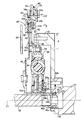
- FIG. 2 is a cross-sectional view for explaining in detail the configuration of the damper device 16 shown in FIG.
- the damper device 16 is provided so that power can be transmitted between the engine 12 and the first planetary gear device 18, that is, the first electric motor MG1, with the axis C1 as the center.
- the damper device 16 includes a disk-like flywheel (first inertia member) 32 connected to the crankshaft 14 of the engine 12, and a plurality of damper fastening bolts on the flywheel 32.
- An input side disk plate (first plate) 36 connected by a (second fastening member) 34 and a transaxle input shaft 38 connected to the carrier CA1 of the first planetary gear unit 18 are connected so as not to be relatively rotatable.
- a bubb plate (second plate) 40, an output side disk plate (third plate) 44 connected to the hub plate 40 via a torque limiter mechanism (torque limiter) 42, and an output side disk plate 44 Provided in the drive transmission path with the input side disk plate 36, the relative rotation between the output side disk plate 44 and the input side disk plate 36.
- a coiled damper springs 46 to be elastically deformed according to the displacement is provided.
- the driving force from the engine 12 is, for example, flywheel 32, input side disk plate 36, damper spring 46, output side disk plate 44, torque limiter mechanism 42, hub plate 40, transaxle input shaft 38. It is a structure that is transmitted in this order.
- the hub plate 40 is a substantially disk-shaped member that extends from the tip of the transaxle input shaft 38 in a direction approaching the torque limiter mechanism 42, and the hub plate 40 includes a central portion 40 a of the hub plate 40.
- a cylindrical portion 40b is formed so as to protrude integrally from the input side disk plate 36 side, that is, toward the tip end side of the crankshaft 14.
- the tip end portion of the transaxle input shaft 38 is spline-fitted into the cylindrical portion 40b of the hub plate 40.
- a fitting hole 14 a is formed at the tip of the crankshaft 14, and between the inner peripheral surface 14 b of the fitting hole 14 a and the outer peripheral surface 40 c of the tip of the tube portion 40 b of the bubb plate 40.
- the 1st bearing (bearing) 48 is interposed in this.
- the torque limiter mechanism 42 includes a pair of cover plates 52 and 54 that sandwich the outer peripheral edge portion 40d of the hub plate 40 and the outer peripheral edge portion 44a of the output side disk plate 44 via a disc spring (spring) 50 and are connected to each other.
- materials 56 and 58 are used to be used to be used to each other.
- the torque limiter mechanism 42 presses the outer peripheral edge portion 40d of the hub plate 40 and the outer peripheral edge portion 44a of the output side disk plate 44 through the friction materials 56 and 58 by the biasing force of the disc spring 50,
- the outer peripheral edge 44a of the output side disk plate 44 slides with respect to the outer peripheral edge 40d of the hub plate 40, thereby causing the hub plate 40 to slide. This prevents excessive torque from being transmitted to the motor.
- the torque limiter mechanism 42 is provided with an annular inertia ring (second inertia member) 60 positioned on the outer peripheral side of the flywheel 32. That is, the torque limiter mechanism 42 to which the inertia ring 60 is fixed is disposed outside the flywheel 32, the input side disk plate 36, the damper fastening bolt 34, and the like, and uses the outer peripheral space of the flywheel 32. Be placed.
- the inertia ring 60 is provided between the outer peripheral portions of the pair of cover plates 52 and 54.
- the pair of cover plates 52 and 54 and the inertia ring 60 are fastened by an inertia ring fastening bolt (first fastening member) 62.
- the inertia ring 60 is disposed at a position overlapping with the cover plate 52 and the disc spring 50 in the radial direction.
- the inertia ring fastening bolt 62 is fastened from the transaxle side and can be removed from the transaxle side.
- the output-side disk plate 44 is a substantially disk-shaped member that extends from the outside of the front end portion of the transaxle input shaft 38 in a direction approaching the torque limiter mechanism 42.
- a cylindrical portion 44c is formed so as to protrude from the central portion 44b of the side disc plate 44 in a cylindrical shape in a direction approaching the crankshaft 14 side.
- the input side disk plate 36 is integrally provided with a pair of substantially disc-shaped side plates 66 and 68 fixed to the inner periphery of the input side disk plate 36 by rivets 64.
- the side plate 66 is formed with a cylindrical portion 66b that protrudes in a cylindrical shape from the central portion 66a of the side plate 66 so as to approach the crankshaft 14 side.
- a second bearing 70 is interposed between the peripheral surface 66 c and the outer peripheral surface 44 d of the cylindrical portion 44 c of the output side disk plate 44.
- the hub plate 40 has six insertion holes for inserting a fastening tool (not shown) for fastening a plurality of (six in this embodiment) damper fastening bolts 34 between the center portion 40a and the outer peripheral edge portion 40d. 40e penetrates.
- the output-side disk plate 44 is formed with six communication holes 44e communicating with the six insertion holes 40e formed in the hub plate 40 between the central portion 44b and the outer peripheral edge portion 44a.
- the damper device 16 is removed from the flywheel 32 by inserting the fastening tool from the transaxle side into the insertion hole 40 e formed in the hub plate 40 and removing the damper fastening bolt 34. Can be removed. Further, in the torque limiter mechanism 42, the phase of the insertion hole 40e with respect to the sliding communication hole 44e changes with respect to the outer peripheral edge portion 40d of the hub plate 40 when the outer peripheral edge portion 44a of the output side disk plate 44 changes, and the damper fastening bolt 34 is removed.
- the inertia fastening bolt 62 is loosened to allow the output side disk plate 44 and the hub plate 40 to rotate relative to each other, and the communication hole 44e of the output side disk plate 44 and the insertion hole 40e of the hub plate 40 Since the positions can be adjusted, the damper device 16 can be removed from the flywheel 32 as described above.
- the inertia ring 60 is provided in the torque limiter mechanism 42, that is, the inertia ring 60 is provided on the motor MG 1 side.
- a force F1, ie, an unbalanced load F1 is applied to the torque limiter mechanism 42
- a force F2, ie, an eccentric load F2, indicated by a broken line is applied to the torque limiter mechanism 42.
- the unbalance load F ⁇ b> 1 is input to the engine 12 side via the output side disk plate 44 and the second bearing 70
- the eccentric load F ⁇ b> 2 is input via the hub plate 40 and the first bearing 48. Since the input is made to the engine 12 side, excessive input of the load to the transaxle input shaft 38 due to the inertia ring 60 being provided on the electric motor MG1 side is suitably suppressed.
- the torque limiter 42 is provided with the inertia ring 60 positioned on the outer peripheral side of the flywheel 32, so that, for example, the flywheel 32 is connected to the damper device 16. It is possible to dispose the inertia ring 60 in the space where the flywheel 32 and the like are accommodated by being arranged inside. For this reason, the inertia ring 60 can be added to the electric motor MG1 side to increase the inertia on the electric motor MG1 side, and an increase in the space for accommodating the damper device 16 can be suppressed. In addition, since the inertia ring 60 is disposed on the outer peripheral side of the flywheel 32, the mass of the inertia ring 60 is easily increased, and the inertia on the electric motor MG1 side is easily increased.
- the torque limiter mechanism 42 is sandwiched between the outer peripheral edge portion 40d of the hub plate 40 and the outer peripheral edge portion 44a of the output side disk plate 44 via the disc spring 50 and is connected to each other.
- the inertia ring 60 is provided at a position overlapping with the cover plate 52 and the disc spring 50 in the radial direction. For this reason, even if the inertia ring 60 is provided in the torque limiter mechanism 42, an increase in the space of the damper device 16 in the direction of the axis C1 of the damper device 16 can be suitably suppressed.
- the inertia ring 60 is provided between the pair of cover plates 52 and 54, and the pair of cover plates 52 and 54 and the inertia ring 60 are engaged with the inertia ring. Fastened with bolts 62. For this reason, even if the inertia ring 60 is provided in the torque limiter mechanism 42, an increase in the space of the damper device 16 in the direction of the axis C1 of the damper device 16 can be suitably suppressed.
- the central portion 40 a of the hub plate 40 is provided with the cylindrical tube portion 40 b protruding toward the input side disk plate 36, and the hub plate 40 A first bearing 48 is provided between the cylinder portion 40 b and the crankshaft 14 of the engine 12.
- the eccentric load F2 due to the addition of the inertia ring 60 to the electric motor MG1 side is received and centered on the crankshaft 14 of the engine 12 via the hub plate 40 and the first bearing 48, so the electric motor MG1 side
- the mass of the inertia ring 60 can be increased relatively easily without improving the strength of the member.
- the flywheel 32 and the input side disk plate 36 are connected by the plurality of damper fastening bolts 34, and the torque limiter mechanism 42 is configured by the outer peripheral edge portion 40 d of the hub plate 40.
- the outer peripheral edge 44a of the output side disk plate 44, and the hub plate 40 is provided with an insertion hole 40e for a fastening tool for fastening the damper fastening bolt 34. Therefore, the damper device 16 can be removed from the flywheel 32 by inserting a fastening tool into the insertion hole 40 e formed in the hub plate 40 and removing the plurality of damper fastening bolts 34.
- the damper device 80 of the present embodiment is different in that an inertia ring 82 having a larger mass than the inertia ring 60 of the damper device 16 of the first embodiment described above is provided in the torque limiter mechanism 42.
- the other configuration is substantially the same.
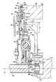
- the inertia ring 82 is formed in an annular shape and is arranged on the outer peripheral side of the flywheel 32. That is, the torque limiter mechanism 42 to which the inertia ring 82 is fixed is arranged outside the flywheel 32, the input side disk plate 36, the damper fastening bolt 34, and the like, and uses the outer peripheral space of the flywheel 32. Be placed.
- the inertia ring 82 is disposed at a position overlapping with the cover plate 52 and the flywheel 32 in the radial direction.
- the inertia ring 82 having a larger mass than the inertia ring 60 of the first embodiment and capable of setting the inertia on the motor MG1 side to be relatively large is provided.
- the damper device 80 can be suitably applied when the forcing force by the engine 12 such as a cylinder or two cylinders is large.
- the damper device 84 of the present embodiment is different in that the inertia ring 60 (see the left diagram of FIG. 4) of the damper device 16 of the first embodiment described above is not attached.
- the rest of the configuration is substantially the same.
- the annular cover plate 52 on the input side disk plate 36 side of the pair of cover plates 52 and 54 of the first embodiment is formed on the outer periphery of the cover plate 52.
- a plate-like first plate portion 52a that comes into contact with the inertia ring 60 and a plate-like second plate portion 52b that comes into contact with the disc spring 50 formed on the inner peripheral portion of the cover plate 52 are integrally provided.
- the second plate portion 52b is bent closer to the hub plate 40 than the first plate portion 52a in the direction of the axis C2 of the inertia ring fastening bolt 62.
- the cover plate 52 is turned over, and the first plate portion 52 a of the cover plate 52 is brought into contact with the outer peripheral portion 54 a of the cover plate 54.
- the pair of cover plates 52 and 54 are connected by inertia ring fastening bolts 62 with the second plate portion 52 b of the cover plate 52 in contact with the disc spring 50.
- the cover plate 52 includes the plate-like first plate portion 52a that contacts the inertia ring 60 formed on the outer peripheral portion of the cover plate 52, and the A plate-like second plate portion 52b that is in contact with the disc spring 50 formed on the inner peripheral portion of the cover plate 52 is integrally provided, and the second plate portion 52b is a hub rather than the first plate portion 52a. It is bent on the plate 40 side. For this reason, for example, when the inertia ring 60 is removed from the torque limiter mechanism 42, the cover plate 52 is turned over, and the first plate portion 52a of the cover plate 52 is brought into contact with the outer peripheral portion 54a of the cover plate 54.
- the second plate portion 52 b of 52 can be brought into contact with the disc spring 50.
- the cover plate 52 can be used in the presence or absence of the inertia ring 60 in the damper device 16 and the damper device 84.
- the inertia ring 60 is provided at a position overlapping with the cover plate 52 and the disc spring 50 in the radial direction.
- the inertia ring 82 is the cover.
- the inertia rings 60 and 82 are provided at positions overlapping with the plate 52 and the flywheel 32 in the radial direction.
- the inertia rings 60 and 82 are arranged in the radial direction with at least one of the pair of cover plates 52 and 54, the disc spring 50, and the flywheel 32. May be provided at overlapping positions.
- the outermost diameter A of the flywheel 32 is arranged radially inward of the inertia rings 60 and 82.
- the outermost diameter A of the flywheel 32 is set by the torque limiter mechanism 42. May also be arranged radially inward.
Landscapes
- Engineering & Computer Science (AREA)
- General Engineering & Computer Science (AREA)
- Mechanical Engineering (AREA)
- Physics & Mathematics (AREA)
- Acoustics & Sound (AREA)
- Aviation & Aerospace Engineering (AREA)
- Chemical & Material Sciences (AREA)
- Combustion & Propulsion (AREA)
- Transportation (AREA)
- Hybrid Electric Vehicles (AREA)
Abstract
Description
14:クランク軸(軸)
16、80、84:ダンパ装置
32:フライホイール(第1の慣性部材)
34:ダンパ締結ボルト(第2締結部材)
36:入力側ディスクプレート(第1のプレート)
40:ハブプレート(第2のプレート)
40a:中心部
40b:筒部
40d:外周縁部
40e:挿入穴
42:トルクリミッタ機構(トルクリミッタ)
44:出力側ディスクプレート(第3のプレート)
44a:外周縁部
46:ダンパスプリング
48:第1軸受(軸受)
50:皿ばね(スプリング)
52、54:一対のカバープレート
52a:第1板部
52b:第2板部
60、82:イナーシャリング(第2の慣性部材)
62:イナーシャリング締結ボルト(第1締結部材)
MG1:第1電動機(電動機)
Claims (6)
- エンジンと電動機とを備え、該エンジンと電動機との駆動伝達経路に配置されるダンパ装置であって、
前記ダンパ装置は、前記エンジンの軸と連結された第1の慣性部材と、該第1の慣性部材に連結された第1のプレートと、前記電動機に連結された第2のプレートと、前記第1のプレートと相対回転可能に設けられた該第2のプレートとトルクリミッタを介して連結された第3のプレートと、該第3のプレートと該第1のプレートとの駆動伝達経路に設けられたダンパスプリングとを含み、
前記トルクリミッタには、前記第1の慣性部材の外周側に位置する第2の慣性部材が設けられていることを特徴とするダンパ装置。 - 前記トルクリミッタは、前記第2のプレートおよび前記第3のプレートの外周部をスプリングを介して挟み且つ互いに連結された一対のカバープレートを含み、
前記第2の慣性部材は、前記一対のカバープレート、前記スプリング、前記第1の慣性部材のうちの少なくとも1つと径方向において重複する位置に設けられている請求項1のダンパ装置。 - 前記第2の慣性部材は、前記一対のカバープレートとの間に設けられており、
前記一対のカバープレート、前記第2の慣性部材は、第1締結部材により締結されている請求項2のダンパ装置。 - 前記第2のプレートの中心部には、前記第1のプレート側に突き出された筒状の筒部が備えられており、
前記筒部と前記エンジンの軸との間には、軸受が設けられている請求項1乃至3のいずれか1のダンパ装置。 - 前記第1の慣性部材と前記第1のプレートとは、第2締結部材により連結され、
前記トルクリミッタは、前記第2のプレートの外周縁部と前記第3のプレートの外周縁部とを挟圧しており、
前記第2のプレートには、前記第2締結部材を締結する締結工具の挿入穴が設けられている請求項1乃至4のいずれか1のダンパ装置。 - 前記一対のカバープレートの前記第1のプレート側には、該カバープレートの外周部に形成された前記第2の慣性部材と当接する板状の第1板部と、該カバープレートの内周部に形成された前記スプリングと当接する板状の第2板部とが備えられており、
前記第2板部は、前記第1板部よりも前記第2のプレート側に曲成されている請求項2のダンパ装置。
Priority Applications (5)
| Application Number | Priority Date | Filing Date | Title |
|---|---|---|---|
| US14/888,784 US20160084318A1 (en) | 2013-05-10 | 2013-05-10 | Damper device |
| JP2015515758A JP6123888B2 (ja) | 2013-05-10 | 2013-05-10 | ダンパ装置 |
| DE112013007052.9T DE112013007052T5 (de) | 2013-05-10 | 2013-05-10 | Dämpfervorrichtung |
| CN201380076483.7A CN105209277A (zh) | 2013-05-10 | 2013-05-10 | 减震器装置 |
| PCT/JP2013/063194 WO2014181471A1 (ja) | 2013-05-10 | 2013-05-10 | ダンパ装置 |
Applications Claiming Priority (1)
| Application Number | Priority Date | Filing Date | Title |
|---|---|---|---|
| PCT/JP2013/063194 WO2014181471A1 (ja) | 2013-05-10 | 2013-05-10 | ダンパ装置 |
Publications (1)
| Publication Number | Publication Date |
|---|---|
| WO2014181471A1 true WO2014181471A1 (ja) | 2014-11-13 |
Family
ID=51866970
Family Applications (1)
| Application Number | Title | Priority Date | Filing Date |
|---|---|---|---|
| PCT/JP2013/063194 Ceased WO2014181471A1 (ja) | 2013-05-10 | 2013-05-10 | ダンパ装置 |
Country Status (5)
| Country | Link |
|---|---|
| US (1) | US20160084318A1 (ja) |
| JP (1) | JP6123888B2 (ja) |
| CN (1) | CN105209277A (ja) |
| DE (1) | DE112013007052T5 (ja) |
| WO (1) | WO2014181471A1 (ja) |
Cited By (4)
| Publication number | Priority date | Publication date | Assignee | Title |
|---|---|---|---|---|
| JPWO2014181471A1 (ja) * | 2013-05-10 | 2017-02-23 | トヨタ自動車株式会社 | ダンパ装置 |
| JP2018123944A (ja) * | 2017-02-03 | 2018-08-09 | 株式会社エクセディ | 動力伝達装置 |
| CN114083980A (zh) * | 2020-08-24 | 2022-02-25 | 舍弗勒技术股份两合公司 | 用于驱动系的具有旋转轴线的混合动力模块 |
| JP2022542605A (ja) * | 2019-07-31 | 2022-10-05 | ヴァレオ アンブラヤージュ | ねじり振動減衰装置 |
Families Citing this family (4)
| Publication number | Priority date | Publication date | Assignee | Title |
|---|---|---|---|---|
| JP6531685B2 (ja) * | 2016-03-16 | 2019-06-19 | アイシン・エィ・ダブリュ株式会社 | ダンパ装置 |
| DE102017120530A1 (de) * | 2017-09-06 | 2019-03-07 | Schaeffler Technologies AG & Co. KG | Rutschkupplung mit einer Rotationsachse |
| DE102017121437A1 (de) | 2017-09-15 | 2019-03-21 | Schaeffler Technologies AG & Co. KG | Drehmomentbegrenzer für einen Antriebsstrang |
| DE102019204842A1 (de) * | 2019-04-04 | 2020-10-08 | Zf Friedrichshafen Ag | Drehschwingungsdämpfer |
Citations (5)
| Publication number | Priority date | Publication date | Assignee | Title |
|---|---|---|---|---|
| JPH1151119A (ja) * | 1997-07-31 | 1999-02-23 | Exedy Corp | フライホイール組立体 |
| JP2011012705A (ja) * | 2009-06-30 | 2011-01-20 | Mitsubishi Heavy Ind Ltd | トルクリミッタ装置 |
| JP2012087899A (ja) * | 2010-10-20 | 2012-05-10 | Toyota Motor Corp | トルクリミッタ機構を備えたダンパ装置 |
| JP2012127410A (ja) * | 2010-12-15 | 2012-07-05 | Toyota Motor Corp | トルクリミッタ付ダンパ装置 |
| WO2012124014A1 (ja) * | 2011-03-11 | 2012-09-20 | トヨタ自動車株式会社 | 振動減衰装置 |
Family Cites Families (11)
| Publication number | Priority date | Publication date | Assignee | Title |
|---|---|---|---|---|
| DE8504809U1 (de) * | 1985-02-21 | 1985-05-30 | Fichtel & Sachs Ag, 8720 Schweinfurt | Geteiltes Schwungrad mit Rutschkupplung |
| JP3230713B2 (ja) * | 1992-10-23 | 2001-11-19 | トヨタ自動車株式会社 | ピークトルク低減機構 |
| DE19709343B4 (de) * | 1997-03-07 | 2010-04-08 | Zf Sachs Ag | Torsionsschwingungsdämpfer mit einer Reibvorrichtung |
| FR2871204B1 (fr) * | 2004-06-08 | 2007-09-28 | Valeo Embrayages | Double volant amortisseur, en particulier pour vehicule automobile |
| JP5098825B2 (ja) * | 2008-06-03 | 2012-12-12 | アイシン精機株式会社 | トルク変動吸収装置 |
| JP5458612B2 (ja) * | 2009-03-13 | 2014-04-02 | アイシン精機株式会社 | ダンパ装置 |
| JP5326719B2 (ja) * | 2009-03-24 | 2013-10-30 | アイシン精機株式会社 | トルク変動吸収装置 |
| JP5338616B2 (ja) * | 2009-10-28 | 2013-11-13 | アイシン精機株式会社 | ダンパ装置 |
| JP5699477B2 (ja) * | 2010-08-06 | 2015-04-08 | アイシン精機株式会社 | ダンパ装置 |
| CN103221714B (zh) * | 2010-11-19 | 2015-07-29 | 丰田自动车株式会社 | 车辆用减振装置 |
| WO2014181471A1 (ja) * | 2013-05-10 | 2014-11-13 | トヨタ自動車株式会社 | ダンパ装置 |
-
2013
- 2013-05-10 WO PCT/JP2013/063194 patent/WO2014181471A1/ja not_active Ceased
- 2013-05-10 DE DE112013007052.9T patent/DE112013007052T5/de not_active Ceased
- 2013-05-10 US US14/888,784 patent/US20160084318A1/en not_active Abandoned
- 2013-05-10 JP JP2015515758A patent/JP6123888B2/ja active Active
- 2013-05-10 CN CN201380076483.7A patent/CN105209277A/zh active Pending
Patent Citations (5)
| Publication number | Priority date | Publication date | Assignee | Title |
|---|---|---|---|---|
| JPH1151119A (ja) * | 1997-07-31 | 1999-02-23 | Exedy Corp | フライホイール組立体 |
| JP2011012705A (ja) * | 2009-06-30 | 2011-01-20 | Mitsubishi Heavy Ind Ltd | トルクリミッタ装置 |
| JP2012087899A (ja) * | 2010-10-20 | 2012-05-10 | Toyota Motor Corp | トルクリミッタ機構を備えたダンパ装置 |
| JP2012127410A (ja) * | 2010-12-15 | 2012-07-05 | Toyota Motor Corp | トルクリミッタ付ダンパ装置 |
| WO2012124014A1 (ja) * | 2011-03-11 | 2012-09-20 | トヨタ自動車株式会社 | 振動減衰装置 |
Cited By (6)
| Publication number | Priority date | Publication date | Assignee | Title |
|---|---|---|---|---|
| JPWO2014181471A1 (ja) * | 2013-05-10 | 2017-02-23 | トヨタ自動車株式会社 | ダンパ装置 |
| JP2018123944A (ja) * | 2017-02-03 | 2018-08-09 | 株式会社エクセディ | 動力伝達装置 |
| WO2018142889A1 (ja) * | 2017-02-03 | 2018-08-09 | 株式会社エクセディ | 動力伝達装置 |
| JP2022542605A (ja) * | 2019-07-31 | 2022-10-05 | ヴァレオ アンブラヤージュ | ねじり振動減衰装置 |
| JP7494286B2 (ja) | 2019-07-31 | 2024-06-03 | ヴァレオ アンブラヤージュ | ねじり振動減衰装置 |
| CN114083980A (zh) * | 2020-08-24 | 2022-02-25 | 舍弗勒技术股份两合公司 | 用于驱动系的具有旋转轴线的混合动力模块 |
Also Published As
| Publication number | Publication date |
|---|---|
| JPWO2014181471A1 (ja) | 2017-02-23 |
| CN105209277A (zh) | 2015-12-30 |
| DE112013007052T5 (de) | 2016-03-17 |
| JP6123888B2 (ja) | 2017-05-10 |
| US20160084318A1 (en) | 2016-03-24 |
Similar Documents
| Publication | Publication Date | Title |
|---|---|---|
| JP6123888B2 (ja) | ダンパ装置 | |
| JP5561375B2 (ja) | 車両用ダンパ装置 | |
| EP2696101B1 (en) | Torsional vibration damping device | |
| CN106090039B (zh) | 车辆的动力传递结构 | |
| JP6036700B2 (ja) | 車両用動力伝達装置 | |
| JP5656949B2 (ja) | 車両のダンパ装置 | |
| JP5488441B2 (ja) | トルクリミッタ付ダンパ装置 | |
| JP5439935B2 (ja) | 駆動力伝達装置 | |
| JP5983861B2 (ja) | 車両用ダンパ装置 | |
| CN104136253A (zh) | 混合动力车辆的驱动装置 | |
| JP2014184923A (ja) | 車両用動力伝達装置 | |
| WO2012085966A1 (ja) | 捩り振動減衰装置 | |
| JP2014181785A (ja) | 捩り振動減衰装置 | |
| KR20180068789A (ko) | 변속기용 더블 클러치 장치 | |
| JP5859940B2 (ja) | 車両のダンパ装置 | |
| JP6167839B2 (ja) | 車両用ダンパ装置 | |
| JP5673460B2 (ja) | 車両用ダンパ装置 | |
| JP2019077203A (ja) | ハイブリッド車両用動力伝達装置 | |
| WO2012164647A1 (ja) | 車両のトルクリミッタ装置 | |
| JP2010216524A (ja) | 車両用トルクリミッタ装置 | |
| CN114542662A (zh) | 具有离合器的减振装置 | |
| JP2019199209A (ja) | 車両用動力伝達装置 | |
| CN114542663A (zh) | 扭矩传递装置及混合动力系统 | |
| JP2013087884A (ja) | 車両用ダンパ装置 | |
| JPH07305754A (ja) | 電磁石式差動制限装置 |
Legal Events
| Date | Code | Title | Description |
|---|---|---|---|
| 121 | Ep: the epo has been informed by wipo that ep was designated in this application |
Ref document number: 13884284 Country of ref document: EP Kind code of ref document: A1 |
|
| WWE | Wipo information: entry into national phase |
Ref document number: 14888784 Country of ref document: US |
|
| ENP | Entry into the national phase |
Ref document number: 2015515758 Country of ref document: JP Kind code of ref document: A |
|
| WWE | Wipo information: entry into national phase |
Ref document number: 112013007052 Country of ref document: DE Ref document number: 1120130070529 Country of ref document: DE |
|
| 122 | Ep: pct application non-entry in european phase |
Ref document number: 13884284 Country of ref document: EP Kind code of ref document: A1 |