WO2012085966A1 - 捩り振動減衰装置 - Google Patents
捩り振動減衰装置 Download PDFInfo
- Publication number
- WO2012085966A1 WO2012085966A1 PCT/JP2010/007416 JP2010007416W WO2012085966A1 WO 2012085966 A1 WO2012085966 A1 WO 2012085966A1 JP 2010007416 W JP2010007416 W JP 2010007416W WO 2012085966 A1 WO2012085966 A1 WO 2012085966A1
- Authority
- WO
- WIPO (PCT)
- Prior art keywords
- rotating member
- cam
- cam surface
- damping device
- torsional vibration
- Prior art date
Links
Images


Classifications
-
- F—MECHANICAL ENGINEERING; LIGHTING; HEATING; WEAPONS; BLASTING
- F16—ENGINEERING ELEMENTS AND UNITS; GENERAL MEASURES FOR PRODUCING AND MAINTAINING EFFECTIVE FUNCTIONING OF MACHINES OR INSTALLATIONS; THERMAL INSULATION IN GENERAL
- F16D—COUPLINGS FOR TRANSMITTING ROTATION; CLUTCHES; BRAKES
- F16D13/00—Friction clutches
- F16D13/58—Details
- F16D13/60—Clutching elements
- F16D13/64—Clutch-plates; Clutch-lamellae
-
- F—MECHANICAL ENGINEERING; LIGHTING; HEATING; WEAPONS; BLASTING
- F16—ENGINEERING ELEMENTS AND UNITS; GENERAL MEASURES FOR PRODUCING AND MAINTAINING EFFECTIVE FUNCTIONING OF MACHINES OR INSTALLATIONS; THERMAL INSULATION IN GENERAL
- F16F—SPRINGS; SHOCK-ABSORBERS; MEANS FOR DAMPING VIBRATION
- F16F15/00—Suppression of vibrations in systems; Means or arrangements for avoiding or reducing out-of-balance forces, e.g. due to motion
- F16F15/10—Suppression of vibrations in rotating systems by making use of members moving with the system
- F16F15/12—Suppression of vibrations in rotating systems by making use of members moving with the system using elastic members or friction-damping members, e.g. between a rotating shaft and a gyratory mass mounted thereon
- F16F15/1204—Suppression of vibrations in rotating systems by making use of members moving with the system using elastic members or friction-damping members, e.g. between a rotating shaft and a gyratory mass mounted thereon with a kinematic mechanism or gear system
- F16F15/1205—Suppression of vibrations in rotating systems by making use of members moving with the system using elastic members or friction-damping members, e.g. between a rotating shaft and a gyratory mass mounted thereon with a kinematic mechanism or gear system with a kinematic mechanism, i.e. linkages, levers
Definitions
- the present invention relates to a torsional vibration damping device, and in particular, is interposed between an internal combustion engine of a vehicle and a drive system so that rotational torque is transmitted between a first rotating member and a second rotating member.
- the present invention relates to a torsional vibration damping device in which a first rotating member and a second rotating member are connected to each other via an elastic member so as to be relatively rotatable.
- a torsional vibration that couples with a driving source such as an internal combustion engine or an electric motor and wheels to transmit rotational torque from the driving source and absorbs a torsional vibration between the driving source and a drive system having a transmission gear set.
- a driving source such as an internal combustion engine or an electric motor and wheels to transmit rotational torque from the driving source and absorbs a torsional vibration between the driving source and a drive system having a transmission gear set.
- Attenuator devices are known.
- the torsional vibration damping device includes, for example, a first rotating member that is fastened and released to a flywheel on the drive source side, a second rotating member that is connected to an input shaft of the transmission, a first rotating member, and It is comprised from the elastic member which connects the 2nd rotation member elastically in the circumferential direction (for example, refer patent document 1).
- the first rotating member is composed of a clutch disk and a pair of disk plates provided radially inward of the clutch disk.
- the second rotating member is non-rotatable with respect to the input shaft of the transmission and has an axis line. It is composed of a hub that is movably connected in the direction and is provided between the disk plates.
- the hub has a cylindrical boss that is spline-engaged with the input shaft and a disk-shaped flange that extends radially outward from the boss.
- the elastic member is composed of a single coil spring.
- the coil spring is housed in a window hole formed in the flange, and both ends in the circumferential direction are supported in the circumferential direction. It is supported in the circumferential direction by a window formed in the disk plate.
- the coil spring is disposed in the circumferential direction between the clutch disk, the pair of disk plates and the hub. By being compressed, the torsional vibration input from the first rotating member to the second rotating member is absorbed and damped by the coil spring.
- rattling the noise during idling is called rattling that occurs when a gear pair in an unloaded state collides due to torsional vibration caused by rotational fluctuation caused by torque fluctuation of the driving source during idling after shifting to neutral.
- An unusual noise, a so-called rattling sound, is known.
- the idle gear pair of the transmission gear set collides with torsional vibration caused by rotational fluctuation caused by torque fluctuation of the driving source or torsional resonance of the driving system during acceleration / deceleration of the vehicle.
- jagged noise the so-called jagged sound.
- abnormal noise that is generated in the passenger compartment due to vibration caused by torsional resonance of the driving system that uses torque fluctuation of the driving source as an excitation force is known as a booming noise. Since there is a time (for example, the rotational speed of the internal combustion engine is around 2000 rpm), a muffled noise is generated during steady running.
- the torsional vibration damping device includes a first rotating member that rotates integrally with the internal combustion engine, a second rotating member that is coaxially and relatively rotatable with the first rotating member, and a first rotating member.
- a contact portion that is formed on the member and moves along a contacted surface configured to change a curvature according to a relative rotation angle between the first rotation member and the second rotation member;
- a displacement member that is displaced relative to the second rotating member by moving the contact portion along the contacted surface of the first rotating member following the relative rotation between the rotating member and the second rotating member.
- an elastic member that compresses following the relative displacement of the displacement member.
- the displacement member relatively displaces following the torsion angle, and the compression of the elastic member is defined by this relative displacement, so the torsional characteristics can be defined by the displacement member, the contacted surface, and the elastic member.
- the torsion angle between the first rotating member and the second rotating member can be widened by using an elastic member having low rigidity, and the first rotation is performed, for example, when shifting to neutral in the idle state.
- the vibration can be attenuated by the low-rigid elastic member to suppress the generation of a rattling sound.
- the torsion angle of the first rotating member and the second rotating member is increased to increase the rate of torque increase.
- the torsional angle between the first rotating member and the second rotating member is widened to reduce the rigidity of the elastic member in the region where the jagged noise and the booming noise are generated. Since the curvature of the contacted surface is constant, when the second rotating member is twisted with respect to the first rotating member, the torsional characteristic is such that the amount of bending (rigidity) of the elastic member gradually increases. .
- the elastic member having a small rigidity when used in order to widen the torsion angle between the first rotating member and the second rotating member, the amount of bending of the elastic member is increased in accordance with the widening of the angle. In addition, a large elastic member is required.
- an installation space for installing a large-sized elastic member must be secured in the first rotating member and the second rotating member, and the torsional vibration damping device may be increased in size.
- the present invention was made to solve the conventional problems as described above, and can reduce the torsional vibration in a necessary region by reducing the installation space while reducing the size of the elastic member,
- An object of the present invention is to provide a torsional vibration damping device that can prevent the entire device from becoming large.
- a torsional vibration damping device includes a first rotating member, a second rotating member provided on the same axis as the first rotating member, and the first rotation. Between the first rotating member and the second rotating member when the first rotating member and the second rotating member rotate relative to each other. At least one elastic member elastically deformed between the first rotating member and the second rotating member, and the first rotating member and the second rotating member.
- a cam surface of the cam member is provided on an axis extending in a longitudinal direction, and an outer periphery of a first circle having a radius around the rotation center axis of the cam member, and the rotation center It is composed of a curved surface that is connected to the outer periphery of a pair of second circles having a radius larger than the radius of the first circle, centered on a rotation center axis that is spaced outward from the shaft in both axial directions.
- the cam surface of the cam member is provided on an axis extending in the longitudinal direction, the outer periphery of a first circle having a radius centered on the rotation center axis of the cam member, and the rotation center axis
- the cam surface of the cam member has a curved surface that connects the outer periphery of a pair of second circles having a radius larger than the radius of the first circle, centered on the rotation center axis that is axially separated from each other in the axial direction.
- the torque transmission member slides along the cam surface, and the cam surface biases the elastic member via the torque transmission member, thereby The torque transmission member presses the cam surface by the reaction force of the deforming elastic member, whereby the rotational torque can be transmitted between the first rotating member and the second rotating member.
- the torsional vibration damping device is interposed between the drive source of the vehicle and the transmission of the drive system having the transmission gear set to transmit the rotational torque from the drive source to the first rotary member, and the second rotary member
- the rotational torque is transmitted from the transmission to the transmission
- the twist angle between the first rotation member and the second rotation member is small, one end of the torque transmission member is moved from the cam surface on the outer periphery of the first circle to the second
- the torsional rigidity of the first rotating member and the second rotating member can be reduced by contacting the cam surface that is continuous with the cam surface on the outer periphery of the circle.
- the drive source It is possible to attenuate the torsional vibration caused by the rotational fluctuation caused by the torque fluctuation of the transmission and suppress the generation of a rattling sound from the gear pair of the transmission in the no-load state.
- the rotational torque transmitted from the first rotating member to the second rotating member (the rotational speed of the internal combustion engine is 1500 rpm or more) is large, a large torsion using rotational fluctuation due to torque fluctuation of the drive source as a vibration source Vibration and torsional resonance in the drive system are attenuated, and a jull noise generated by collision of the idle gear pair of the transmission gear set and a torsion due to torsional resonance in the drive system are generated.
- the region between the idle region where the rattling sound is generated and the region where the jagged sound and the booming sound are generated is a region where it is not necessary to reduce the rigidity of the elastic member.
- the peanut shape of the cam member is such that the curvature of the cam surface continuing from the cam surface on the outer periphery of the first circle to the cam surface on the outer periphery of the second circle is smaller than the curvature of the cam surface on the outer periphery of the second circle. Therefore, when the one end portion of the torque transmitting member comes into contact with the cam surface on the outer periphery of the second circle from the cam surface on the outer periphery of the first circle, the torsion of the first rotating member and the second rotating member It is possible to increase the rigidity of the elastic member by rapidly increasing the amount of bending of the elastic member with respect to the change amount of the angle.
- the amount of deformation of the elastic member with respect to the amount of deformation of the torsion angle from the idle region where the rattling sound is generated to the region where the jagged sound and the booming sound are generated as in the conventional case, in the present invention, Increase the amount of deformation of the elastic member relative to the amount of change in the torsion angle from the idle area where the rattling noise occurs to the area where the jalling and booming noise occurs.
- the deformation amount (rigidity) of the elastic member with respect to the amount can be reduced, and the elastic member can be made low in rigidity.
- the elastic member is enlarged by increasing the elastic deformation amount of the elastic member corresponding to the deformation amount of the torsion angle from the state in which the torsion angle of the first rotation member and the second rotation member is small to the large state. Can be prevented. In other words, it is not necessary to gently deform the elastic member from a state where the twist angle of the first rotating member and the second rotating member is small to a large state as in the prior art. There is no need to make it bigger.
- the elastic member is reduced in size to reduce the installation space for the elastic member, and torsional vibration is achieved by reducing the rigidity of the elastic member in the necessary areas (areas where the rattling noise and the area where the jagged noise and the booming noise occur).
- the torsional vibration damping device can be prevented from increasing in size.
- one end of the torque transmitting member extends from the cam surface on the outer periphery of the first circle to the outer periphery of the second circle. It may be configured to move toward the cam surface.
- the curvature of the cam surface continuing from the cam surface on the first circle to the cam surface on the second circle is the same as that of the cam surface on the second circle. Since the curvature of the curved surface can be made smaller, when the one end portion of the torque transmission member comes into contact with the cam surface on the second circle from the cam surface on the first circle, The rigidity of the elastic member can be increased by rapidly increasing the amount of bending of the elastic member with respect to the amount of change in the twist angle of the second rotating member.
- the radius of the second circle is constant, when one end of the torque transmitting member moves along the second circle as the torsion angle of the first rotating member and the second rotating member increases.
- the amount of bending of the elastic member can be reduced with respect to the amount of change in the twist angle of the first rotating member and the second rotating member, thereby reducing the rigidity of the elastic member.
- the curvature of the cam surface that continues from the outer circumferential cam surface of the first circle to the outer circumferential cam surface of the second circle is smaller than the curvature of the outer circumferential cam surface of the second circle. May be.
- the curvature of the cam surface continuing from the outer circumferential cam surface of the first circle to the outer circumferential cam surface of the second circle is smaller than the curvature of the outer circumferential cam surface of the second circle.
- the torque transmission member includes a swing fulcrum provided on either the first rotation member or the second rotation member between one end and the other end of the torque transmission member. You may comprise from what rocks to the center.
- the torsional vibration damping device has a simple configuration in which an elastic member, a torque transmission member, and a cam member are provided between the first rotating member and the second rotating member, and the first rotating member and the second rotating member. Since the torque can be transmitted between them, the configuration of the torsional vibration damping device can be simplified.
- the torque transmission member may be configured to be arranged point-symmetrically with respect to a central axis of the first rotating member.
- the torque transmission member clamps the cam member with a strong pressing force across the central axis of the first rotating member by the reaction force of the elastic member. To do. For this reason, rotational torque can be more reliably transmitted between the first rotating member and the second rotating member, and the first rotating member and the second rotating member can be reliably rotated integrally. .
- the second rotating member includes a boss member having the cam member on an outer peripheral portion and connected to an input shaft of a transmission provided in a drive system of the vehicle on the inner peripheral portion.
- the rotating members are arranged on both sides in the axial direction of the first rotating member, are fixed to each other at a predetermined interval in the axial direction, and a receiving portion for receiving the elastic member is formed in the circumferential direction.
- a pair of disk plates; and a pair of holding members that support both ends in the circumferential direction of the elastic member and support the elastic member on both ends in the circumferential direction of the accommodating portion, and the other end of the torque transmission member A part may be comprised from what contact
- an elastic member is accommodated in the accommodating portion of the pair of disk plates, and both ends in the circumferential direction of the elastic member are supported by both ends in the circumferential direction of the accommodating portion by the pair of holding members, and torque Since the other end portion of the transmission member comes into contact with one end portion in the circumferential direction of the elastic member through one of the holding members, the range of the twist angle between the first rotating member and the second rotating member can be set.
- the angle can be increased to reduce the rigidity of the elastic member, and the rotational torque can be smoothly transmitted from the first rotating member to the second rotating member.
- a rolling member is provided at the other end portion of the torque transmission member, and the other end portion of the torque transmission member is in contact with one of the pair of holding members via the rolling member. Also good.
- the other end of the torque transmission member moves inward in the radial direction of the first rotation member.
- the other end portion of the torque transmitting member is brought into contact with one of the holding members via the rolling member, so that the other end portion of the torque transmitting member is along the one abutting surface of the holding member via the rolling member.
- the elastic member can be elastically deformed in the circumferential direction of the first rotating member while smoothly sliding in the radial direction.
- a hysteresis mechanism that frictionally contacts the cam member and the pair of disk plates may be interposed between the cam member and the pair of disk plates.
- an attenuation device can be provided.
- FIG. 1 is a view showing an embodiment of a torsional vibration damping device according to the present invention, and is a cross-sectional view taken along the line AA in FIG. It is a figure which shows one Embodiment of the torsional vibration damping device which concerns on this invention, and is B direction arrow sectional drawing of FIG. It is a figure which shows one Embodiment of the torsional vibration damping device which concerns on this invention, and is C direction arrow sectional drawing of FIG.
- FIG. 6 is a diagram showing an embodiment of a torsional vibration damping device according to the present invention, and is a cross-sectional view in the DD direction of FIG. It is a figure which shows one Embodiment of the torsional vibration damping device which concerns on this invention, and is a figure explaining a cam member a component. It is a figure which shows one Embodiment of the torsional vibration damping device which concerns on this invention, and is a front view of a cam member.
- FIGS. 1 to 15 are diagrams showing an embodiment of a torsional vibration damping device according to the present invention.
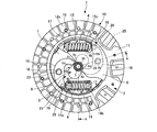
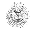
- a torsional vibration damping device 1 is provided on the same axis as the first rotating member 2 to which rotational torque from an internal combustion engine (not shown) that is a drive source is input, and the first rotating member 2.
- the second rotating member 3 Provided between the first rotating member 2 and the second rotating member 3, the second rotating member 3 for transmitting the rotational torque of the first rotating member 2 to a transmission of a drive system (not shown),
- a pair of coil springs 4 are provided as elastic members that are compressed in the circumferential direction of the first rotating member 2 when the first rotating member 2 and the second rotating member 3 rotate relative to each other.
- the second rotating member 3 is provided on the outer periphery of the boss 5 and the boss 5 as a boss member as a second rotating member that is spline-fitted to the outer periphery of the input shaft 21 of the drive-line transmission. And a cam member 6.
- the boss 5 and the cam member 6 may be integrally formed. Further, the boss 5 and the cam member 6 are formed separately, spline portions are formed on the outer peripheral portion of the boss 5 and the inner peripheral portion of the cam member 6, and the boss 5 and the cam member 6 are spline-fitted. Also good.
- the first rotating member 2 includes a pair of disk plates 7 and 8 and a clutch disk 10.
- the disk plates 7 and 8 are disposed on both sides of the boss 5 in the axial direction, and are connected to each other by a pin 9 and a pin 18 as a swinging fulcrum at a predetermined interval in the axial direction.
- boss 5 is accommodated in the circular center holes 7 a and 8 a of the disc plates 7 and 8, and the boss 5 is provided on the same axis as the disc plates 7 and 8.
- the pins 9 and 18 are bridged to the disk plates 7 and 8, and both end portions in the axial direction are formed with large diameters, so that the pins 9 and 18 are locked to the disk plates 7 and 8. For this reason, the disk plates 7 and 8 are integrally rotated by being integrated by the pins 18 and 9.
- the clutch disk 10 is provided radially outward of the disk plate 7, and includes a cushioning plate 11 and friction materials 12a and 12b.
- the cushioning plate 11 is composed of a ring-shaped member that undulates in the thickness direction, and is fixed to the disk plates 7 and 8 by pins 9.
- the friction materials 12a and 12b are fixed to both surfaces of the cushioning plate 11 by rivets 13, and the friction materials 12a and 12b are bolted to a flywheel (not shown) fixed to a crankshaft of an internal combustion engine and a flywheel. Located between the pressure plates of the clutch cover.
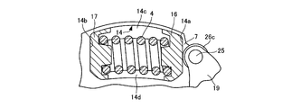
- the disc plates 7 and 8 are respectively formed with a pair of receiving holes 14 and 15 that are spaced apart in the circumferential direction, and the receiving holes 14 and 15 are formed in the axial direction of the disc plates 7 and 8.
- the coil spring 4 is accommodated so as to face the surface.
- the receiving holes 14 and 15 are punched out by a press on the outer peripheral side of the coil spring 4, and both end portions in the circumferential direction of the disk plates 7 and 8 are closed ends.
- the disk plates 7 and 8 include outer support pieces (accommodating portions) 14c and 15c extending in the circumferential direction along the radially outer edges of the accommodating holes 14.
- Inner support pieces (accommodation holes) 14d and 15d extending in the circumferential direction along the radially inner edge of the accommodation hole 14 are provided.
- the outer support pieces 14c and 15c and the inner support pieces 14d and 15d are provided as follows.
- the disk plates 7 and 8 protrude outward in the axial direction.
- both ends in the circumferential direction of the coil spring 4 are held by spring sheets 16 and 17 which are holding members, and end windings are formed on the inner peripheral surfaces of the spring sheets 16 and 17.
- This end turn corresponds to one or two turns at both ends of the coil spring 4 in the circumferential direction, and both end portions in the circumferential direction of the coil spring 4 are seated on this end turn.
- the coil spring 4 can be prevented from rotating and can be attached to the spring seats 16 and 17 by engaging the start and end of the rotational direction with the end winding.
- the closed ends of the circumferential ends of the disk plates 7 and 8 are the contact portions 14a, 14b and 15a with which the circumferential ends of the spring seats 16 and 17 abut. 15b, and in a state where the spring seats 16 and 17 are extended, the circumferential ends of the spring seats 16 and 17 come into contact with the contact portions 14a, 14b, 15a and 15b.
- the outer peripheral portions of the spring seats 16 and 17 are opposed to the outer support pieces 14c and 15c and the inner support pieces 14d and 15d, and the spring sheets 16 and 17 are provided with the outer support pieces 14c and 15c and the inner support pieces 14d, 15d prevents the receiving holes 14 and 15 from coming out.
- An arm member 19 serving as a torque transmission member is provided between the spring seat 16 on one side in the circumferential direction and the cam member 6, and this arm member 19 is located between the disk plates 7 and 8 and is attached to the pin 18. It is swingably supported.
- a needle bearing 20 is interposed between the pin 18 and the arm member 19.
- the needle bearing 20 includes an outer race 20a attached to the arm member 19, and a needle needle 20b interposed between the outer race 20a and the pin 18, and the outer race 20a removes the needle needle 20b.
- the arm member 19 is rotatably attached to the pin 18 via the needle bearing 20.
- the other end of the arm member 19 is formed with bifurcated protruding pieces 19c and 19d, and the protruding pieces 19c and 19d are connected by a pin 25.
- the pin 25 is supported by the protruding pieces 19c and 19d.
- a roller member 26 as a rolling member is rotatably attached to the pin 25.
- the roller member 26 includes an outer race 26a provided on the outer peripheral portion of the pin 25, a needle bearing made up of a needle needle 26b interposed between the outer race 26a and the pin 25, and an outer race on the outer peripheral portion of the outer race 26a.
- the roller 26c is attached to the roller 26a.
- the roller 26c is rotatable with respect to the pin 25 via a needle bearing.
- the roller 26c comes into contact with the outer circumferential surface of the spring seat 16, and the other end of the arm member 19 comes into contact with the outer circumferential surface of the spring seat 16 through the roller 26c.
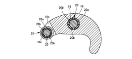
- the cam member 6 is formed in a peanut shape, and the cam surface of the cam member 6 has a peanut shape.
- the cam surface 6A of the cam member 6 includes an outer periphery 51a of a first circle 51 having a radius r1 centered on the rotation center axis O1 of the cam member 6, and an axis L direction from the rotation center axis O1.
- the radius r2 of the pair of second circles 52 has the same size.
- the curvatures of the cam surfaces 6c and 6d that are continuous from the cam surface 6a of the outer periphery 51a of the first circle 51 to the cam surface 6b of the outer periphery 52a of the second circle 52 are the cam surfaces of the outer periphery 52a of the second circle 52. It is smaller than the curvature of 6b.
- the cam surface 6a of the outer periphery 51a of the first circle 51 is a point on the outer periphery 51a of the first circle 51, whereas the cam of the outer periphery 52a of the second circle 52 is The surface 6b extends in the circumferential direction of the outer periphery 51a of the second circle 52 connecting the terminal ends of the cam surfaces 6c and 6d.
- the arm member 19 is arranged point-symmetrically with respect to the central axis of the disk plates 7, 8, that is, the rotational central axis O 1 of the cam member 6, and the cam surface sandwiches the rotational central axis O 1 of the cam member 6. 6A is in contact.
- the tip of the arm member 19 is in contact with the cam surface 6a. At this time, the rotation center axis O1 is sandwiched. The separation distance of the arm member 19 is the shortest.
- the cam member 6 rotates in this way, and the position of the cam surface 6A where one end of the arm member 19 abuts is varied, whereby the spring seat 16 is biased by the arm member 19 and the coil The amount of compression of the spring 4 is variable. At this time, the spring seat 16 moves along the periphery of the accommodation holes 14 and 15 so as to approach and separate from the spring seat 17.
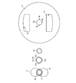
- a hysteresis mechanism 27 is interposed between the disk plates 7 and 8 and the cam member 6, and the hysteresis mechanism 27 is an annular friction material 28, 29, 30, 31. And a disc spring 32.
- the friction materials 28 and 29 are made of a member having a predetermined friction coefficient on the surface, and are fixed to the outer circumferential surface of the cam member 6 in the axial direction by an adhesive.
- the friction members 28 and 29 are integrally provided with pins and the like, and the pins are fitted into pin holes formed on the outer circumferential surface of the cam member 6 in the axial direction, whereby the friction members 28 and 29 are attached to the cam member 6. It may be attached.
- the friction material 30 is composed of a member having a predetermined friction coefficient on the surface, and is fixed to the inner peripheral surface of the disk plate 7 with an adhesive.
- a pin or the like may be integrally provided on the friction material 30 and the pin may be attached to the disc plate 7 by fitting it into a pin hole formed on the inner peripheral surface of the disc plate 7.
- the friction material 31 is formed of a member having a predetermined friction coefficient on the surface, and a plurality of pins 31a are integrally provided on the radially outer peripheral surface.
- the pin 31 a is fitted into a pin hole 8 b formed on the inner peripheral surface of the disk plate 8, and the friction material 31 is attached to the inner peripheral surface of the disk plate 8.
- the disc spring 32 is formed in a conical shape, and is interposed between the friction material 31 and the disk plate 8.
- the disc spring 32 generates an elastic force in the axial direction of the cam member 6, thereby bringing the friction material 31 and the friction material 28 into frictional contact, and bringing the friction material 29 and the friction material 30 into friction contact.
- the cam member 6 and the disk plates 7 and 8 are brought into frictional contact with each other to generate hysteresis torque between the cam member 6 and the disk plates 7 and 8.
- the hysteresis mechanism may be configured such that the friction materials 28 and 29 are eliminated and the friction materials 30 and 31 are directly brought into frictional contact with the outer circumferential surface of the cam member 6 in the axial direction.
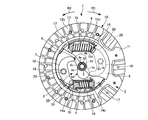
- 10 and 11 show a state in which the disk plates 7 and 8 are rotating in the counterclockwise rotation direction (R2 direction) from the state of FIG. 1 in response to the rotational torque of the internal combustion engine.
- R2 direction counterclockwise rotation direction
- the description will be made assuming that the disk plates 7 and 8 are twisted in the clockwise direction (R1 direction) on the positive side.
- the boss 5 is twisted to the positive side with respect to the disk plates 7 and 8 when the vehicle is accelerated.
- the friction materials 12 a and 12 b are pressed against the pressure plate and frictionally engaged with the flywheel and the pressure plate, whereby the rotational torque of the internal combustion engine is input to the disk plates 7 and 8.
- the relative rotation between the disk plates 7 and 8 and the boss 5 is small, that is, the torsion angle between the disk plates 7 and 8 and the boss 5 is small near 0 °.
- the cam member 6 is positioned at the initial position and rotates integrally with the boss 5.
- the arm member 19 uses the pin 18 as a fulcrum by the reaction force of the coil spring 4 and presses the cam member 6 according to the lever principle. Therefore, the rotational torque of the disk plates 7 and 8 is transmitted to the cam member 6 via the coil spring 4 and the arm member 19. For this reason, the rotational torque of the internal combustion engine is transmitted to the input shaft of the transmission, and at this time, the amount of compression of the coil spring 4 is small.
- the other end portion of the arm member 19 moves along the circumferential outer circumferential surface of the spring seat 16 via the roller 26c, so that the spring seat 16 can be prevented from moving in the circumferential direction.
- the spring seat 16 since one end in the circumferential direction of the spring seat 17 is in contact with the contact portions 14 b and 15 b, the spring seat 16 extends along the periphery of the accommodation holes 14 and 15. The coil spring 4 is compressed by moving to the spring seat 17 side.
- the arm member 19 biases the coil spring 4 in this way, so that the arm member 19 uses the pin 18 as a fulcrum by the reaction force of the coil spring 4 to be compressed, and the cam member 6 is pressed with a strong pressing force by the lever principle. Press.
- the one end portion of the arm member 19 when one end portion of the arm member 19 moves from the cam surface 6d to the cam surface 6b, the one end portion of the arm member 19 has a short distance in the short direction and the short direction from the cam surface 6d of the cam member 6 having a small curvature. Since the distance is abutted against the cam surface 6b having a long curvature, the amount of compression of the coil spring 4 with respect to the torsion angles of the disk plates 7 and 8 and the boss 5 increases, and the rigidity of the coil spring 19 increases.
- the arm member 19 uses the pin 18 as a fulcrum by the reaction force of the coil spring 4 compressed by the arm member 19 and the cam member 6, and presses the cam member 6 with a strong pressing force according to the lever principle.
- the coil spring 4 is made to have low rigidity and the power of the drive system is transmitted from the boss 5 to the disk plates 7 and 8 while the disk plates 7 and 8 are transmitted. And torsional vibration of the boss 5 can be absorbed and damped.
- the other end portion of the arm member 19 moves along the circumferential outer peripheral surface of the spring seat 16 via the roller 26c so as not to prevent the spring seat 16 from moving in the circumferential direction. Can be.
- the cam member 6 can function as a torque limiter during acceleration of the vehicle.
- the arm member 19 Since the curvature of the cam surface 6c is larger than the curvature of the cam surface 6b, the arm member 19 is counterclockwise via the pin 18 when one end of the arm member 19 moves from the cam surface 6d to the cam surface 6b. It rotates greatly in the direction of rotation.
- the one end portion of the arm member 19 when one end portion of the arm member 19 moves from the cam surface 6c to the cam surface 6b, the one end portion of the arm member 19 has a short distance in the short direction and the short direction from the cam surface 6c of the cam member 6 having a small curvature. Since the distance is abutted against the cam surface 6b having a long curvature, the amount of compression of the coil spring 4 with respect to the torsion angles of the disk plates 7 and 8 and the boss 5 increases, and the rigidity of the coil spring 19 increases.
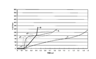
- the torsional characteristics of the torsional vibration damping device 1 during acceleration will be described with reference to FIG. Note that the torsional characteristics at the time of deceleration are the same as those at the time of acceleration, and thus description thereof is omitted.
- one end of the arm member 19 moves along the cam surface 6d having a smaller curvature than the cam surface 6b. As indicated by the region a1, the rigidity of the coil spring 4 is low.
- the torsion angle between the disk plates 7 and 8 and the boss 5 is further increased and one end portion of the arm member 19 moves from the cam surface 6d to the cam surface 6b, the one end portion of the arm member 19 is a distance in the short direction. Is short and the cam surface 6d of the cam member 6 having a small curvature is in contact with the cam surface 6b having a long short distance and a large curvature. Therefore, the compression amount of the coil spring 4 with respect to the torsion angles of the disc plates 7 and 8 and the boss 5 And the rigidity of the coil spring 19 increases as shown in the region a2.
- the cam surface 6b 2 is formed in the same circular shape as the outer periphery 52a of the circle 52, the compression amount of the coil spring 4 with respect to the torsion angles of the disk plates 7 and 8 and the boss 5 gradually increases, as shown by a region a3.
- the coil spring 4 has low rigidity.
- the torsional vibration damping device disclosed in Patent Document 2 can widen the torsion angle of the disk plate (first rotating member) and the boss (second rotating member), but the curvature of the contacted surface is constant. For this reason, when the boss is twisted with respect to the disk plate, the torsion characteristic is such that the amount of bending (rigidity) of the coil spring gradually increases.
- FIG. 14 is a characteristic diagram showing the relationship between the rotational speed of the internal combustion engine and the torque fluctuation of the internal combustion engine.
- the torque increases in a steady rotational region where the rotational speed of the internal combustion engine is 1500 rpm or more and is driven near 2000 rpm. Assume that torsional resonance of the system occurs.
- the torsional characteristics of the torsional vibration damping device 1 it is preferable to set the torsional characteristics of the torsional vibration damping device 1 so that the torsional rigidity of the torsional vibration damping device 1 (the rigidity of the coil spring 4) is reduced around 2000 rpm.
- the shape of the cam member 6 is formed in a peanut shape, and the first end of the cam member 6 is moved so that one end of the arm member 19 is moved along the cam surface 6b of the cam member 6 in the rotation region of 2000 rpm.
- the rigidity of the coil spring 4 can be made low (region a3 in FIG. 13), and due to torque fluctuations of the drive source Reduces torsional vibration caused by rotational fluctuations, and torsional resonance in the drive system to reduce the noise caused by the collision of the idle gear pair of the transmission gear set and the torsional resonance caused by the torsional resonance of the drive system be able to.
- one end of the arm member 19 is moved along the cam surface 6d having a smaller curvature than the cam surface 6b.
- the rigidity of the coil spring 4 can be reduced, and the torsional vibration caused by the rotational fluctuation caused by the torque fluctuation of the drive source can be attenuated, and the transmission gear pair in the unloaded state can be attenuated. Generation of a rattling sound can be suppressed.
- a large torsional vibration such as a jarr sound or a booming noise does not occur in an area between an idle region where a rattling sound is generated and a region where a jallah sound or a booming sound is generated. Therefore, the coil spring 4 does not need to have low rigidity.
- the cam member 6 is formed in a peanut shape, and one end portion of the arm member 19 is brought into contact with the cam surface 6b from the cam surface 6d of the cam member 6, so 5 is provided to increase the rigidity of the coil spring 4 by rapidly increasing the amount of bending of the coil spring 4 with respect to the amount of change in the torsion angle 5.
- the cam surface 6A of the cam member 6 is aligned with the outer circumference 51a of the first circle 51 having the radius r1 centered on the rotation center axis O1 of the cam member 6 and the rotation center axis O1.
- the curvature of the cam surfaces 6c and 6d formed in a curved surface and continuing from the cam surface 6a of the outer periphery 51a of the first circle 51 to the cam surface 6b of the outer periphery 52a of the second circle 52 is the outer periphery 52a of the second circle 52.
- the torsional angle between the disk plates 7 and 8 and the boss 5 can be increased to about half that of the torsional vibration damping device disclosed in Patent Document 2, and the coil spring 4 is downsized.
- the torsional vibration can be efficiently damped in the necessary regions (the region where the rattling sound is generated and the region where the jagged sound and the booming sound are generated).
- the cam member 6 can be functioned as a torque limiter.
- the roller 26c is rotatably provided at the other end of the arm member 19, and the other end of the arm member 19 is in contact with the spring seat 16 via the roller 26c.
- the coil spring 4 can be elastically deformed in the circumferential direction of the disk plates 7 and 8 while the other end of 19 is smoothly slid along the circumferential outer peripheral surface of the spring seat 16 via the roller member 26. it can.
- twist angles of the disk plates 7 and 8 and the boss 5 are simply configured by simply providing the coil spring 4, the arm member 19 and the cam member 6 between the disk plates 7 and 8 and the boss 5. Can be widened, and the configuration of the torsional vibration damping device 1 can be simplified.
- the arm member 19 is arranged point-symmetrically with respect to the central axis of the disk plates 7 and 8, so the arm member 19 sandwiches the central axis of the disk plates 7 and 8 and the cam member 6. Can be pinched.
- the torsional characteristics and the torsional angle when the disk plates 7 and 8 and the boss 5 rotate relative to each other depend on the shape of the cam surface 6A of the cam member 6 (the radii r1 and r2 of the circles 51 and 52, the circle 51, (Separation distance of rotation center axes O1 and O2 of 52, etc.)
- the shape of the arm member 19, etc. it is possible to set an arbitrary twist characteristic and twist angle.
- the torsional vibration damping device 1 is interposed between the internal combustion engine of the vehicle and the drive system having the transmission.
- the present invention is not limited to this, and is provided in the drive system of the vehicle or the like. Any torsional vibration damping device can be used.
- the present invention is applied to a torsional vibration damping device such as a hybrid damper interposed between an output shaft of an internal combustion engine and a power split mechanism that splits power into an electric motor and a wheel side output shaft. May be.
- the present invention may be applied to a torsional vibration damping device such as a lockup damper interposed between a lockup clutch device of a torque converter and a transmission gear set. Further, a torsional vibration damping device may be provided between the differential case and a ring gear provided on the outer periphery of the differential case.
- a torsional vibration damping device such as a lockup damper interposed between a lockup clutch device of a torque converter and a transmission gear set.
- a torsional vibration damping device may be provided between the differential case and a ring gear provided on the outer periphery of the differential case.
- the torsional vibration damping device can reduce the size of the elastic member, reduce the installation space and attenuate the torsional vibration in a necessary region, and increase the size of the entire device.
- the rotation torque is transmitted between the first rotation member and the second rotation member.
- the rotation torque is transmitted between the internal combustion engine of the vehicle and the drive system.
- it is useful as a torsional vibration damping device or the like in which the first rotating member and the second rotating member are connected to each other via an elastic member so as to be relatively rotatable.
Abstract
【課題】第1の回転部材と第2の回転部材の捩れ角の範囲を広角化して大きな捩れ振動の抑制を図りつつ、第1の回転部材および第2の回転部材が中立位置に変位したときに正側と負側に交互に捩れてしまうのを防止することができる捩り振動減衰装置を提供することを特徴とする。捩り振動減衰装置1は、ボス5と、ボス5の外周部に設けられてボス5と一体回転するカム面6Aを有するカム部材6と、カム部材6とコイルスプリング4との間に設けられ、一端部がカム面6Aに接触するとともに他端部がコイルスプリング4のスプリングシート16に当接し、ディスクプレート7、8に橋架されたピン18を中心に揺動するアーム部材19とを備え、カム面6Aの曲率が、ボス5がディスクプレート7、8に対して正側に捩れたときに、アーム部材19の一端部が接触するカム面6Aの曲率に対して、ボス5がディスクプレート7、8に対して中立位置から負側に捩れたときにアーム部材19の一端部が接触するカム面6Aの曲率が大きいものから構成される。
Description
本発明は、捩り振動減衰装置に関し、特に、車両の内燃機関と駆動系との間に介装され、第1の回転部材と第2の回転部材との間で回転トルクが伝達されるように第1の回転部材と第2の回転部材とを弾性部材を介して相対回転自在に連結した捩り振動減衰装置に関する。
従来から内燃機関や電動モータ等の駆動源と車輪等と連結して駆動源からの回転トルクを伝達するとともに、駆動源と変速歯車組を有する駆動系との間の捩り振動を吸収する捩り振動減衰装置が知られている。
この捩り振動減衰装置は、例えば、駆動源側のフライホイールに締結および解放される第1の回転部材と、変速機の入力軸に連結される第2の回転部材と、第1の回転部材および第2の回転部材を円周方向に弾性的に連結する弾性部材とから構成されている(例えば、特許文献1参照)。
第1の回転部材は、クラッチディスクと、クラッチディスクの半径方向内方に設けられた一対のディスクプレートから構成されており、第2の回転部材は、変速機の入力軸に回転不能にかつ軸線方向に移動可能に連結され、ディスクプレートの間に設けられたハブから構成されている。
ハブは、入力軸にスプライン係合する筒状のボスおよびボスから半径方向外方に広がる円板状のフランジを有している。また、弾性部材は、単独のコイルスプリングから構成されており、コイルスプリングは、フランジに形成された窓孔内に収容されて円周方向両端部を円周方向に支持されているとともに、一対のディスクプレートに形成された窓部によって円周方向に支持されている。
このような構成を有する捩り振動減衰装置にあっては、クラッチディスクおよび一対のディスクプレートとハブとが相対回転すると、コイルスプリングがクラッチディスクおよび一対のディスクプレートとハブとの間で円周方向に圧縮されることにより、第1の回転部材から第2の回転部材に入力される捩り振動をコイルスプリングによって、吸収・減衰するようになっている。
ところで、捩り振動によって発生する変速機側の騒音としては、アイドリング時の異音、走行時の異音およびこもり音等が知られている。したがって、各異音の発生原因となる捩り振動を吸収するためには、捩り振動減衰装置の捩れ特性を適切に設定する必要がある。
ここで、アイドル時の異音としては、ニュートラルに変速したアイドル時に、駆動源のトルク変動による回転変動を起振源とした捩り振動によって、無負荷状態にある歯車対が衝突して生じるガラガラという異音、所謂、ガラ音が知られている。
また、走行時の異音としては、車両の加減速中に、駆動源のトルク変動による回転変動を起振源とした捩り振動や、駆動系の捩り共振によって変速歯車組の空転歯車対が衝突して生じるジャラジャラという異音、所謂、ジャラ音が知られている。
また、こもり音としては、駆動源のトルク変動を起振力とする駆動系の捩り共振による振動によって車室内に発生する異音が知られており、駆動系の捩り共振は、通常、定常走行時(例えば、内燃機関の回転数が2000rpm付近)に存在するため、定常走行時にこもり音が発生する。
従来、捩れ特性を適切に設定した捩り振動減衰装置としては、例えば、特許文献2に記載されたようなものが知られている。
この捩り振動減衰装置は、内燃機関と一体に回転する第1の回転部材と、第1の回転部材と同軸的、かつ相対回転自在に配設される第2の回転部材と、第1の回転部材に形成され、第1の回転部材と第2の回転部材との相対回転角度に応じて曲率が変化するように構成される被接触面に沿って移動する接触部を有し、第1の回転部材と第2の回転部材との相対回転に追従して接触部が第1の回転部材の被接触面に沿って移動することにより、第2の回転部材に対して相対変位する変位部材と、変位部材の相対変位に追従して圧縮する弾性部材とを備えている。
この捩れ角減衰装置は、内燃機関が駆動すると第1の回転部材が回転駆動し、弾性部材を介して第1の回転部材の回転駆動が第2の回転部材に伝達される。内燃機関のトルクが変動して第1の回転部材と第2の回転部材とが相対回転すると、変位部材の接触部が被接触面に沿って移動して、第1の回転部材または第2の回転部材の他方に対して相対変位する。
変位部材が相対変位すると、弾性部材が圧縮し、内燃機関のトルクの変動が吸収されて第2の回転部材に出力される。
このように捩れ角に追従して変位部材が相対変位し、この相対変位によって弾性部材の圧縮が規定されるので、捩れ特性は、変位部材、被接触面および弾性部材により規定することができる。
このため、剛性の低い弾性部材を用いて第1の回転部材と第2の回転部材との捩れ角を広角化することができ、アイドル状態でニュートラルに変速したとき等のように第1の回転部材と第2の回転部材との捩れ角が小さい領域にあっては、低剛性の弾性部材によって振動を減衰してガラ音の発生を抑制することができる。
また、第1の回転部材と第2の回転部材捩れ角が大きい領域では、第1の回転部材と第2の回転部材の捩れ角を大きくしてトルクの上昇率が大きくなる高剛性の捩れ特性を得ることにより、ジャラ音を抑制することができる。
この結果、内燃機関のトルク変動による回転変動を起振源とした大きな捩り振動や、駆動系の捩り共振を減衰して、変速歯車組の空転歯車対が衝突して生じるジャラ音や駆動系の捩り共振によるこもり音の発生を抑制することができる。
このような従来の捩り振動減衰装置にあっては、第1の回転部材と第2の回転部材との捩れ角を広角化してジャラ音やこもり音の発生領域において弾性部材の剛性を低くするが、被接触面の曲率が一定であるため、第2の回転部材が第1の回転部材に対して捩れたときに、弾性部材の撓み量(剛性)が緩やかに大きくなる捩れ特性となってしまう。
このため、第1の回転部材と第2の回転部材との捩れ角の広角化を図って小さい剛性の弾性部材を使用する場合には、広角化に応じて弾性部材の撓み量を多くするために、大型の弾性部材が必要になってしまう。
換言すれば、ジャラ音やこもり音が発生する領域まで第2の回転部材を第1の回転部材に対して捩じる必要があるため、弾性部材の弾性変形を大きくする必要があり、大型な弾性部材が必要になってしまうのである。
したがって、大型の弾性部材を設置するための設置スペースを第1の回転部材および第2の回転部材に確保しなければならず、捩り振動減衰装置が大型化してしまうおそれがある。
本発明は、上述のような従来の問題を解決するためになされたもので、弾性部材を小型化することができるとともに設置スペースを少なくして必要な領域の捩れ振動を減衰することができ、装置全体が大型化するのを防止することができる捩り振動減衰装置を提供することを目的とする。
本発明に係る捩り振動減衰装置は、上記目的を達成するため、第1の回転部材と、前記第1の回転部材と同一軸線上に設けられた第2の回転部材と、前記第1の回転部材と前記第2の回転部材との間に設けられ、前記第1の回転部材および前記第2の回転部材とが相対回転したときに前記第1の回転部材および前記第2の回転部材との間で弾性変形される少なくとも1つ以上の弾性部材と、前記第1の回転部材および前記第2の回転部材のいずれか一方に設けられ、前記第1の回転部材および前記第2の回転部材のいずれか一方と一体回転するカム面を有するカム部材と、一端部が前記カム部材の前記カム面に接触するとともに他端部が前記弾性部材の延在方向一端部に当接し、前記第1の回転部材と前記第2の回転部材とが相対回転したときに、前記一端部が前記カム面に沿って移動して前記弾性部材を弾性変形させることにより、前記第1の回転部材と前記第2の回転部材との間で回転トルクを伝達するトルク伝達部材とを備え、前記カム部材のカム面が、長手方向に延在する軸線上に設けられ、前記カム部材の回転中心軸を中心とした半径を有する第1の円の外周と、前記回転中心軸から前記軸線方向両外方に離隔する回転中心軸を中心とし、前記第1の円の半径よりも大きい半径を有する一対の第2の円の外周とを結んだ曲面を有するものから構成されている。
この捩り振動減衰装置は、カム部材のカム面が、長手方向に延在する軸線上に設けられ、カム部材の回転中心軸を中心とした半径を有する第1の円の外周と、回転中心軸から軸線方向両外方に離隔する回転中心軸を中心とし、第1の円の半径よりも大きい半径を有する一対の第2の円の外周とを結んだ曲面を有するので、カム部材のカム面が、所謂、ピーナッツ形状のカム面となる。
このため、第1の回転部材と第2の回転部材が相対回転したときには、トルク伝達部材がカム面に沿って摺動し、カム面がトルク伝達部材を介して弾性部材を付勢し、弾性変形する弾性部材の反力によってトルク伝達部材がカム面を押圧することにより、第1の回転部材と第2の回転部材との間で回転トルクを伝達することができる。
この捩り振動減衰装置を車両の駆動源と変速歯車組を有する駆動系の変速機との間に介装して第1の回転部材に駆動源からの回転トルクを伝達し、第2の回転部材から変速機に回転トルクを伝達した場合に、第1の回転部材と第2の回転部材の捩れ角が小さいときには、トルク伝達部材の一端部が第1の円の外周のカム面から第2の円の外周のカム面に連続するカム面上に当接することで、第1の回転部材と第2の回転部材の捩れ剛性を小さくすることができる。
したがって、アイドル状態でニュートラルに変速したとき等のように第1の回転部材から第2の回転部材に伝達される回転トルクが小さい領域(例えば、内燃機関の回転数が1000rpm付近)では、駆動源のトルク変動による回転変動を起振源とした捩り振動を減衰して、無負荷状態にある変速機の歯車対からガラ音が発生するのを抑制することができる。
また、第1の回転部材から第2の回転部材に伝達される回転トルク(内燃機関の回転数が1500rpm以上)が大きい領域では、駆動源のトルク変動による回転変動を起振源とした大きな捩り振動や、駆駆動系に捩り共振を減衰して、変速歯車組の空転歯車対が衝突して生じるジャラ音や駆動系の捩り共振によるこもりが発生する。
このときには、ジャラ音やこもり音が発生する1500rpm以上の領域でトルク伝達部材の一端部を第1の円の外周よりも半径が大きい第2の円の外周のカム面に当接させることにより、第1の回転部材と第2の回転部材の捩れ剛性を小さくすることができ、ジャラ音やこもり音を抑制することができる。
また、ガラ音が発生するアイドル領域とジャラ音やこもり音が発生する領域との間の領域は、弾性部材の剛性を低くする必要がない領域である。
カム部材のピーナッツ形状は、第1の円の外周のカム面から第2の円の外周のカム面に連続するカム面の曲率を第2の円の外周のカム面の曲率よりも小さくすることができるため、トルク伝達部材の一端部が第1の円の外周のカム面から第2の円の外周のカム面に当接したときに、第1の回転部材と第2の回転部材の捩れ角の変化量に対して弾性部材の撓み量を急激に大きくして弾性部材の剛性を高くすることができる。
すなわち、従来のようにガラ音が発生するアイドル領域からジャラ音やこもり音が発生する領域までの捩れ角の変形量に対する弾性部材の変形量が緩やかであったのに対して、本発明では、ガラ音が発生するアイドル領域からジャラ音やこもり音が発生する領域までの捩れ角の変化量に対する弾性部材の変形量を大きくして、ジャラ音やガラ音が発生する領域では、捩れ角の変化量に対する弾性部材の変形量(剛性)を少なくすることができ、弾性部材を低剛性にすることができる。
したがって、第1の回転部材と第2の回転部材の捩れ角が小さい状態から大きい状態まで捩れ角の変形量に対応する弾性部材の弾性変形量を大きくすることで、弾性部材が大型化するのを防止することができる。換言すれば、従来のように第1の回転部材と第2の回転部材の捩れ角が小さい状態から大きい状態まで弾性部材を緩やかに変形させる必要がないため、この変形分を見込んで弾性部材を大きくする必要がない。
この結果、弾性部材を小型化して弾性部材の設置スペースを少なくして、必要な領域(ガラ音の発生領域とジャラ音やこもり音の発生領域)で弾性部材の低剛性を図ることで捩れ振動を減衰することができ、捩り振動減衰装置が大型化するのを防止することができる。
好ましくは、第1の回転部材と第2の回転部材との捩れ角が増大するのに伴って、トルク伝達部材の一端部が第1の円の外周のカム面から第2の円の外周のカム面に向かって移動するように構成されてもよい。
この捩り振動減衰装置は、第1の回転部材と第2の回転部材との捩れ角が増大するのに伴って、トルク伝達部材の一端部が第1の円上のカム面から第2の円上のカム面に向かって移動するので、第1の回転部材と第2の回転部材との捩れ角が小さい状態で、トルク伝達部材の一端部を第1の円上のカム面に当接し、第1の回転部材と第2の回転部材との捩れ角が大きくなるにつれてトルク伝達部材の一端部を第1の円上のカム面から第2の円上のカム面に当接させることができる。
本実施の形態のカム部材は、ピーナッツ形状であるため、第1の円上のカム面から第2の円上のカム面に連続するカム面の曲率を、第2の円上のカム面の曲面の曲率よりも小さくすることができるため、トルク伝達部材の一端部が第1の円上のカム面から第2の円上のカム面に当接したときに、第1の回転部材と第2の回転部材の捩れ角の変化量に対して弾性部材の撓み量を急激に大きくして弾性部材の剛性を高くすることができる。
そして、第2の円の半径が一定であるため、第1の回転部材と第2の回転部材の捩れ角が大きくなるにつれてトルク伝達部材の一端部が第2の円上に沿って移動したときに、第1の回転部材と第2の回転部材の捩れ角の変化量に対して弾性部材の撓み量を小さくして弾性部材の剛性を低くすることができる。
好ましくは、前記第1の円の外周のカム面から第2の円の外周のカム面に連続するカム面の曲率が、前記第2の円の外周のカム面の曲率よりも小さいものから構成されてもよい。
この捩り振動減衰装置は、第1の円の外周のカム面から第2の円の外周のカム面に連続するカム面の曲率が、第2の円の外周のカム面の曲率よりも小さいので、トルク伝達部材の一端部が第1の円上のカム面から第2の円上のカム面に当接したときに、第1の回転部材と第2の回転部材の捩れ角の変化量に対して弾性部材の撓み量を急激に大きくして弾性部材の剛性を高くすることができる。
このため、第1の回転部材と第2の回転部材の捩れ角が小さい状態から大きい状態まで弾性部材を緩やかに変形させる必要がないため、この変形分を見込んで弾性部材を大きくするのを不要にできる。
好ましくは、前記トルク伝達部材が、前記トルク伝達部材の一端部と他端部との間で前記第1の回転部材または前記第2の回転部材のいずれか一方に設けられた揺動支点部を中心に揺動するものから構成されてもよい。
この捩り振動減衰装置は、第1の回転部材および第2の回転部材との間に弾性部材、トルク伝達部材およびカム部材を設けるだけの簡素な構成によって第1の回転部材および第2の回転部材との間でトルクを伝達することができるので、捩り振動減衰装置の構成を簡素化することができる。
好ましくは、前記トルク伝達部材が、前記第1の回転部材の中心軸に対して点対称に配置されるものから構成されてもよい。
この捩り振動減衰装置は、トルク伝達部材が第1の回転部材の中心軸に対して点対称に配置されるので、第1の回転部材の中心軸を挟んでトルク伝達部材がカム部材を挟持することになる。
このため、カム部材がトルク伝達部材を介して弾性部材を付勢したときに、弾性部材の反力によってトルク伝達部材が第1の回転部材の中心軸を挟んでカム部材を強い押圧力で挟持する。このため、第1の回転部材と第2の回転部材との間で回転トルクをより確実に伝達することができ、第1の回転部材と第2の回転部材を確実に一体回転させることができる。
好ましくは、前記第2の回転部材が、外周部に前記カム部材を有し、内周部に車両の駆動系に設けられた変速機の入力軸が連結されるボス部材を備え、前記第1の回転部材が、前記第1の回転部材の軸線方向両側に配置され、軸線方向に所定間隔を隔てて互いに固定されるとともに、前記弾性部材が収容される収容部が円周方向に形成された一対のディスクプレートと、前記弾性部材の円周方向両端部を支持して前記弾性部材を前記収容部の円周方向両端部に支持する一対の保持部材とを備え、前記トルク伝達部材の他端部が前記保持部材のいずれか一方を介して前記弾性部材の円周方向一端部に当接するものから構成されてもよい。
この捩り振動減衰装置は、一対のディスクプレートの収容部に弾性部材が収容されるとともに、弾性部材の円周方向両端部が一対の保持部材によって収容部の円周方向両端部に支持され、トルク伝達部材の他端部が保持部材の一方を介して弾性部材の円周方向一端部に当接するようになっているので、第1の回転部材と第2の回転部材との捩れ角の範囲を広角化して弾性部材の低剛性化を図ることができ、第1の回転部材から第2の回転部材に回転トルクを円滑に伝達することができる。
好ましくは、前記トルク伝達部材の他端部に転動部材が設けられ、前記トルク伝達部材の他端部が前記転動部材を介して前記一対の保持部材の一方に当接するように構成されてもよい。
この場合、カム部材の回転によってトルク伝達部材が揺動支点部を介して揺動したときに、トルク伝達部材の他端部が第1の回転部材の半径方向内方に移動してしまう場合に、トルク伝達部材の他端部を転動部材を介して保持部材の一方に当接させることにより、トルク伝達部材の他端部が転動部材を介して保持部材の一方の当接面に沿って円滑に半径方向に摺動しながら弾性部材を第1の回転部材の円周方向に弾性変形させることができる。
好ましくは、前記カム部材と前記一対のディスクプレートとの間に、前記カム部材と前記一対のディスクプレートとを摩擦接触させるヒステリシス機構が介装されるものから構成されてもよい。
この捩り振動減衰装置は、カム部材と一対のディスクプレートとの間にヒステリシス機構が介装されるので、カム部材と一対のディスクプレートとの捩れ角が大きいときにカム部材と一対のディスクプレートとのヒステリシストルクを大きくすることができ、駆動系の捩り共振によるこもり音の発生やジャラ音の発生をより一層抑制することができる。
本発明によれば、弾性部材を小型化することができるとともに設置スペースを少なくして必要な領域の捩れ振動を減衰することができ、装置全体が大型化するのを防止することができる捩り振動減衰装置を提供することができる。
以下、本発明に係る捩り振動減衰装置の実施の形態について、図面を用いて説明する。
図1~図15は、本発明に係る捩り振動減衰装置の一実施の形態を示す図である。
まず、構成を説明する。
図1、図2において、捩り振動減衰装置1は、駆動源である図示しない内燃機関からの回転トルクが入力される第1の回転部材2と、第1の回転部材2と同一軸線上に設けられ、第1の回転部材2の回転トルクを図示しない駆動系の変速機に伝達する第2の回転部材3と、第1の回転部材2と第2の回転部材3との間に設けられ、第1の回転部材2と第2の回転部材3が相対回転したときに第1の回転部材2の円周方向に圧縮される弾性部材としての一対のコイルスプリング4とを備えている。
図1、図2において、捩り振動減衰装置1は、駆動源である図示しない内燃機関からの回転トルクが入力される第1の回転部材2と、第1の回転部材2と同一軸線上に設けられ、第1の回転部材2の回転トルクを図示しない駆動系の変速機に伝達する第2の回転部材3と、第1の回転部材2と第2の回転部材3との間に設けられ、第1の回転部材2と第2の回転部材3が相対回転したときに第1の回転部材2の円周方向に圧縮される弾性部材としての一対のコイルスプリング4とを備えている。
第2の回転部材3は、駆動系の変速機の入力軸21の外周部にスプライン嵌合される第2の回転部材としてのボス部材としてのボス5と、ボス5の外周部に設けられたカム部材6とを含んで構成される。
なお、ボス5とカム部材6とは一体的に成形されてもよい。また、ボス5とカム部材6とを別体に形成し、ボス5の外周部およびカム部材6の内周部にスプライン部をそれぞれ形成し、ボス5とカム部材6とをスプライン嵌合してもよい。
また、第1の回転部材2は、一対のディスクプレート7、8およびクラッチディスク10を備えている。ディスクプレート7、8は、ボス5の軸線方向両側に配置されており、軸線方向に所定間隔を隔ててピン9および揺動支点部としてのピン18によって連接されている。
また、ディスクプレート7、8の円状の中心孔7a、8aにはボス5が収納されており、ボス5は、ディスクプレート7、8と同一軸線上に設けられている。
ピン9、18は、ディスクプレート7、8に橋架されており、軸線方向両端部が大径に形成されることにより、ディスクプレート7、8に抜け止め係止されている。このため、ディスクプレート7、8は、ピン18およびピン9によって一体化されることで一体回転するようになっている。
また、クラッチディスク10は、ディスクプレート7の半径方向外方に設けられており、クッショニングプレート11および摩擦材12a、12bを備えている。クッショニングプレート11は、厚み方向に波打つリング状の部材から構成されており、ピン9によってディスクプレート7、8に固定されている。
摩擦材12a、12bは、クッショニングプレート11の両面にリベット13によって固定されており、この摩擦材12a、12bは、内燃機関のクランクシャフトに固定された図示しないフライホイールとフライホイールにボルト固定されたクラッチカバーのプレッシャプレートの間に位置している。
そして、摩擦材12a、12bがプレッシャプレートに押圧されてフライホイールとプレッシャプレートに摩擦係合することで、内燃機関の回転トルクがディスクプレート7、8に入力される。
また、図示しないクラッチペダルが踏み込まれると、プレッシャプレートが摩擦材12a、12bを押圧するのを解除し、摩擦材12a、12bがフライホイールから離隔することで、内燃機関の回転トルクがディスクプレート7、8に入力されない。
また、ディスクプレート7、8にはそれぞれ収容部としての収容孔14、15が円周方向に離隔して一対ずつ形成されており、この収容孔14、15は、ディスクプレート7、8の軸線方向に対向してコイルスプリング4を収容するようになっている。
また、収容孔14、15は、コイルスプリング4の外周側においてプレスによって打ち抜かれており、ディスクプレート7、8の円周方向両端部が閉止端となっている。
また、図2~図4に示すように、ディスクプレート7、8は、収容孔14の半径方向外方の縁に沿って円周方向に延在する外側支持片(収容部)14c、15cおよび収容孔14の半径方向内方の縁に沿って円周方向に延在する内側支持片(収容孔)14d、15dを備えており、この外側支持片14c、15cおよび内側支持片14d、15dは、ディスクプレート7、8の軸線方向外方に突出している。
また、コイルスプリング4の円周方向両端部は、保持部材であるスプリングシート16、17によって保持されており、このスプリングシート16、17の内周面には座巻が形成されている。
この座巻は、コイルスプリング4の円周方向両端部の一巻分あるいは二巻分に相当しており、この座巻にコイルスプリング4の円周方向両端部を着座させ、コイルスプリング4の巻回方向始端と終端とを座巻に係合させることにより、コイルスプリング4の回転を防止してスプリングシート16、17に装着することができるようになっている。
また、図3、図4に示すように、ディスクプレート7、8の円周方向両端部の閉止端は、スプリングシート16、17の円周方向端部が当接する当接部14a、14b、15a、15bを構成しており、スプリングシート16、17が伸長した状態において、スプリングシート16、17の円周方向端部が当接部14a、14b、15a、15bに当接するようになっている。
また、スプリングシート16、17の外周部は、外側支持片14c、15cおよび内側支持片14d、15dに対向しており、スプリングシート16、17は、外側支持片14c、15cおよび内側支持片14d、15dによって収容孔14、15から抜け出ることが防止される。
円周方向一方のスプリングシート16とカム部材6の間にはトルク伝達部材としてのアーム部材19が設けられており、このアーム部材19は、ディスクプレート7、8の間に位置し、ピン18に揺動自在に支持されている。
図5、図6に示すように、ピン18とアーム部材19の間にはニードルベアリング20が介装されている。ニードルベアリング20は、アーム部材19に取付けられたアウターレース20aと、アウターレース20aとピン18の間に介装された針状ニードル20bとから構成されており、アウターレース20aが針状ニードル20bを介してピン18に対して回転自在となっている。このため、アーム部材19は、ニードルベアリング20を介してピン18に回転自在に取付けられている。
また、アーム部材19の他端部は、二股形状の突出片19c、19dが形成されており、この突出片19c、19dは、ピン25によって連結されている。換言すれば、ピン25は、突出片19c、19dに支持されている。
このピン25には転動部材としてのコロ部材26が回転自在に取付けられている。コロ部材26は、ピン25の外周部に設けられたアウターレース26aおよびアウターレース26aとピン25の間に介装された針状ニードル26bからなるニードルベアリングと、アウターレース26aの外周部でアウターレース26aに取付けられたコロ26cとから構成されており、コロ26cがニードルベアリングを介してピン25に対して回転自在となっている。
コロ26cは、スプリングシート16の円周方向外周面に当接するようになっており、アーム部材19の他端部は、コロ26cを介してスプリングシート16の円周方向外周面に当接する。
また、カム部材6は、ピーナッツ型に形成されており、カム部材6のカム面は、ピーナッツ形状を有している。
図7に示すように、カム部材6のカム面6Aは、カム部材6の回転中心軸O1を中心とした半径r1を有する第1の円51の外周51aと、回転中心軸O1から軸線L方向両外方に等距離に離隔する回転中心軸O2を中心とし、第1の円51の半径よりも大きい半径r2を有する一対の第2の円52の外周52aとを結んだピーナッツ形状の曲面を有しており、一対の第2の円52の半径r2は、同一の大きさとなっている。
そして、第1の円51の外周51aのカム面6aから第2の円52の外周52aのカム面6bに連続するカム面6c、6dの曲率は、第2の円52の外周52aのカム面6bの曲率よりも小さくなっている。
なお、本実施の形態では、第1の円51の外周51aのカム面6aは、第1の円51の外周51a上の一点であるのに対して、第2の円52の外周52aのカム面6bは、カム面6c、6dの終端を結んだ第2の円52の外周51aの円周方向に亘っている。
また、アーム部材19は、ディスクプレート7、8の中心軸、すなわち、カム部材6の回転中心軸O1に対して点対称に配置されており、カム部材6の回転中心軸O1を挟んでカム面6Aに接触している。
本実施の形態では、ディスクプレート7、8とボス5との捩れ角が0°のときには、アーム部材19の先端部は、カム面6aに当接しており、このときには、回転中心軸O1を挟んだアーム部材19の離隔距離は、最も短くなっている。
この状態からディスクプレート7、8とボス5との捩れ角が増大するのに伴って、アーム部材19の一端部が第1の円51上のカム面6aから第2の円52上のカム面6bに向かって移動する。
本実施の形態では、このようにカム部材6が回転してアーム部材19の一端部が当接するカム面6Aの位置が可変されることにより、スプリングシート16がアーム部材19によって付勢されてコイルスプリング4の圧縮量が可変される。このとき、スプリングシート16が収容孔14、15の周縁に沿ってスプリングシート17に近接・離隔するように移動することになる。
一方、図2に示すように、ディスクプレート7、8とカム部材6との間にはヒステリシス機構27が介装されており、このヒステリシス機構27は、環状の摩擦材28、29、30、31および皿ばね32から構成されている。
摩擦材28、29は、表面が所定の摩擦係数を有する部材から構成されており、カム部材6の軸線方向外周面に接着材によって固定されている。なお、摩擦材28、29にピン等を一体的に設け、このピンをカム部材6の軸線方向外周面に形成されたピン穴に嵌合することにより、摩擦材28、29をカム部材6に取付けてもよい。
また、摩擦材30は、表面が所定の摩擦係数を有する部材から構成されており、ディスクプレート7の内周面に接着材によって固定されている。なお、摩擦材30にピン等を一体的に設け、このピンをディスクプレート7の内周面に形成されたピン穴に嵌合することによりディスクプレート7に取付けてもよい。
図9に示すように、摩擦材31は、表面が所定の摩擦係数を有する部材から構成されており、放射方向外周面に複数のピン31aが一体的に設けられている。このピン31aは、ディスクプレート8の内周面に形成されたピン穴8bに嵌合するようになっており、摩擦材31は、ディスクプレート8の内周面に取付けられる。
皿ばね32は、円錐形状に形成されており、摩擦材31とディスクプレート8との間に介装されている。
この皿ばね32は、カム部材6の軸線方向に弾性力を発生させることにより、摩擦材31と摩擦材28とを摩擦接触させるとともに、摩擦材29と摩擦材30とを摩擦接触させることにより、カム部材6とディスクプレート7、8とを摩擦接触させてカム部材6とディスクプレート7、8との間にヒステリシストルクを発生させるようになっている。
なお、ヒステリシス機構としては、摩擦材28、29を廃止して摩擦材30、31をカム部材6の軸線方向外周面に直接摩擦接触させるように構成してもよい。
次に、作用を説明する。
図10、図11は、ディスクプレート7、8が内燃機関の回転トルクを受けて図1の状態から反時計回転方向(R2方向)に回転している状態を示し、説明の便宜上、ボス5がディスクプレート7、8に対して正側の時計回転方向(R1方向)に捩れるものとして説明を行う。
図10、図11は、ディスクプレート7、8が内燃機関の回転トルクを受けて図1の状態から反時計回転方向(R2方向)に回転している状態を示し、説明の便宜上、ボス5がディスクプレート7、8に対して正側の時計回転方向(R1方向)に捩れるものとして説明を行う。
なお、ボス5がディスクプレート7、8に対して正側に捩れるのは、車両の加速時である。
摩擦材12a、12bがプレッシャプレートに押圧されてフライホイールとプレッシャプレートに摩擦係合することで、内燃機関の回転トルクがディスクプレート7、8に入力される。
摩擦材12a、12bがプレッシャプレートに押圧されてフライホイールとプレッシャプレートに摩擦係合することで、内燃機関の回転トルクがディスクプレート7、8に入力される。
本実施の形態の捩り振動減衰装置1は、ディスクプレート7、8とボス5との相対回転が小さい状態、すなわち、ディスクプレート7、8とボス5との捩れ角が0°付近の小さい状態では、図1に示すように、カム部材6が初期位置に位置してボス5と一体回転する。
このとき、アーム部材19の一端部がカム面6a(図8参照)に接触しており、カム部材6がアーム部材19をスプリングシート16に押し付けることにより、コイルスプリング4がカム部材6によって付勢される。
このとき、コイルスプリング4の反力によってアーム部材19がピン18を支点にして、テコの原理によってカム部材6を押圧する。このため、ディスクプレート7、8の回転トルクがコイルスプリング4およびアーム部材19を介してカム部材6に伝達される。このため、変速機の入力軸に内燃機関の回転トルクを伝達することになり、このとき、コイルスプリング4の圧縮量は小さいものとなる。
このため、ディスクプレート7、8からボス5に内燃機関の動力を伝達しつつ、ディスクプレート7、8とボス5との捩り振動を吸収して減衰する。
一方、車両の加速時に、内燃機関のトルク変動による回転変動が小さい場合には、ディスクプレート7、8に対してボス5との間の変動トルクが小さく、ボス5がディスクプレート7、8に対して時計回転方向(R1方向)に相対回転する。
このとき、図1に示す状態から図10に示す状態のように、ディスクプレート7、8とボス5との捩れ角が大きくなるにつれてカム部材6がR1方向に回転すると、アーム部材19の一端部は、カム面6bよりも曲率が小さいカム面6dに沿って移動する。
このとき、アーム部材19の一端部がカム面6dに押圧され、アーム部材19の他端部がディスクプレート7、8の半径方向内方および円周方向に移動する。
そして、カム部材6がR1方向に回転するのに伴って、アーム部材19の他端部がディスクプレート7、8の半径方向内方に移動することにより、スプリングシート16をスプリングシート17に近接させる。
また、アーム部材19の他端部がコロ26cを介してスプリングシート16の円周方向外周面に沿って移動することにより、スプリングシート16が円周方向に移動するのを阻害させないようにできる。
すなわち、図3、図4に示すように、スプリングシート17の円周方向一端部は、当接部14b、15bに当接しているため、スプリングシート16は、収容孔14、15の周縁に沿ってスプリングシート17側に移動することにより、コイルスプリング4を圧縮する。
このようにアーム部材19がコイルスプリング4を付勢することにより、圧縮されるコイルスプリング4の反力によってアーム部材19がピン18を支点にして、テコの原理によってカム部材6を強い押圧力で押圧する。
このとき、アーム部材19の一端部は、短手方向の距離が短いカム部材6のカム面6dに当接しているため、コイルスプリング4の圧縮量が小さくなり、コイルスプリング19の剛性が小さくなる。
このため、ディスクプレート7、8からボス5に伝達される回転トルクが小さい領域では、ディスクプレート7、8からボス5に内燃機関の動力を伝達しつつ、剛性の低いコイルスプリング4によってディスクプレート7、8とボス5との捩り振動を吸収して減衰することができる。
内燃機関のトルク変動による回転変動がさらに大きくなる場合には、ディスクプレート7、8からボス5に伝達される変動トルクが大きく、ボス5がディスクプレート7、8に対して時計回転方向(R1方向)にさらに相対回転する。
図10に示す状態から図11に示す状態のように、ディスクプレート7、8とボス5との捩れ角がさらに大きくなると、アーム部材19の一端部がカム部材6のカム面6dからカム面6bに当接する。
ここで、カム面6dの曲率がカム面6bの曲率よりも大きくなっているため、アーム部材19の一端部がカム面6dからカム面6bに移動したときに、アーム部材19がピン18を介して時計回転方向に大きく回動する。
このとき、カム部材6がアーム部材19をスプリングシート16に押し付けることにより、コイルスプリング4が大きく圧縮される。
すなわち、アーム部材19の一端部がカム面6dからカム面6bに移動したときには、アーム部材19の一端部が短手方向の距離が短く、曲率の小さいカム部材6のカム面6dから短手方向の距離が長く曲率の大きいカム面6bに当接するため、ディスクプレート7、8およびボス5の捩れ角に対するコイルスプリング4の圧縮量が大きくなり、コイルスプリング19の剛性が大きくなる。
このとき、アーム部材19およびカム部材6によって圧縮されるコイルスプリング4の反力によってアーム部材19がピン18を支点にして、テコの原理によってカム部材6を強い押圧力で押圧する。
内燃機関のトルク変動による回転変動がさらに大きくなる場合には、ディスクプレート7、8からボス5に伝達される変動トルクが大きく、ボス5がディスクプレート7、8に対して時計回転方向(R1方向)にさらに相対回転する。
このとき、アーム部材19の一端部が回動するカム部材6のカム面6bに沿って移動する。このカム面6bは、第2の円52の外周52aと同一の円状に形成されているため、ディスクプレート7、8およびボス5の捩れ角に対するコイルスプリング4の圧縮量は、緩やかに大きくなり、コイルスプリング4が低剛性となる。
このため、ディスクプレート7、8およびボス5の捩れ角が大きい領域では、コイルスプリング4を低剛性にしてボス5からディスクプレート7、8に駆動系の動力を伝達しつつ、ディスクプレート7、8とボス5との捩り振動を吸収して減衰することができる。
この場合にも、アーム部材19の他端部がコロ26cを介してスプリングシート16の円周方向外周面に沿って移動することにより、スプリングシート16が円周方向に移動するのを阻害しないようにすることができる。
さらに、ディスクプレート7、8に内燃機関から過大なトルクが入力した場合には、アーム部材19の一端部がカム面6b上を滑ることにより、ディスクプレート7、8をカム部材6に対して空転させることができる。このため、車両の加速時にカム部材6をトルクリミッタとして機能させることができる。
この結果、ディスクプレート7、8からボス5に過大なトルクが伝達されてしまうのを防止して、変速機の変速歯車組を保護することができる。
また、ディスクプレート7、8とカム部材6との間にはヒステリシス機構27が介装されているため、ディスクプレート7、8とカム部材6とが相対回転するときには一定のヒステリシストルクを発生させることができる。
一方、車両の減速時には、内燃機関の駆動トルクが小さくなり、エンジンブレーキが発生するため、変速機の入力軸21からボス5に回転トルクが入力されることになる。減速時に内燃機関のトルク変動による回転変動が小さい場合には、ボス5とディスクプレート7、8との間の変動トルクが小さいため、ボス5がディスクプレート7、8に対して相対的に負側(R2方向)に捩れることになる。
このとき、図1に示す状態から図12に示す状態のように、ディスクプレート7、8とボス5とが相対回転したときに、ディスクプレート7、8とボス5との捩れ角が大きくなるにつれてカム部材6が回転することにより、アーム部材19の一端部がカム面6cからカム面6bに沿って移動する。
カム面6cの曲率がカム面6bの曲率よりも大きくなっているため、アーム部材19の一端部がカム面6dからカム面6bに移動したときに、アーム部材19がピン18を介して反時計回転方向に大きく回動する。
このとき、カム部材6がアーム部材19をスプリングシート16に押し付けることにより、コイルスプリング4が大きく圧縮される。
すなわち、アーム部材19の一端部がカム面6cからカム面6bに移動したときには、アーム部材19の一端部が短手方向の距離が短く、曲率の小さいカム部材6のカム面6cから短手方向の距離が長く曲率の大きいカム面6bに当接するため、ディスクプレート7、8およびボス5の捩れ角に対するコイルスプリング4の圧縮量が大きくなり、コイルスプリング19の剛性が大きくなる。
次に、加速時の捩れ振動減衰装置1の捩れ特性を図13に基づいて説明する。なお、減速時の捩れ特性は、加速時と同様であるため、説明を省略する。
ディスクプレート7、8とボス5との捩れ角が小さい領域では、アーム部材19の一端部がカム面6bよりも曲率が小さいカム面6dに沿って移動しているため、矢印Aで示す線の領域a1で示すように、コイルスプリング4の剛性は、低剛性となる。
また、ディスクプレート7、8とボス5との捩れ角がさらに大きくなり、アーム部材19の一端部がカム面6dからカム面6bに移動したときには、アーム部材19の一端部が短手方向の距離が短く、曲率の小さいカム部材6のカム面6dから短手方向の距離が長く曲率の大きいカム面6bに当接するため、ディスクプレート7、8およびボス5の捩れ角に対するコイルスプリング4の圧縮量が大きくなり、領域a2に示すように、コイルスプリング19の剛性が大きくなる。
そして、ディスクプレート7、8とボス5との捩れ角がさらに大きくなると、アーム部材19の一端部が回動するカム部材6のカム面6bに沿って移動するが、このカム面6bは、第2の円52の外周52aと同一の円状に形成されているため、ディスクプレート7、8およびボス5の捩れ角に対するコイルスプリング4の圧縮量は、緩やかに大きくなり、領域a3で示すように、コイルスプリング4が低剛性となる。
これに対して、特許文献1に示す捩り振動減衰装置は、矢印Bで示すように、ディスクプレートとボスとの捩れ角が増大するのに伴ってコイルスプリングの剛性が大きくなり、ディスクプレートとボスとの捩れ角を広角化することができない。
また、特許文献2に示す捩り振動減衰装置は、ディスクプレート(第1の回転部材)とボス(第2の回転部材)の捩れ角を広角化することができるが、被接触面の曲率が一定であるため、ボスがディスクプレートに対して捩れたときに、コイルスプリングの撓み量(剛性)が緩やかに大きくなる捩れ特性となってしまう。
図14は、内燃機関の回転数と内燃機関のトルク変動の関係を示す特性図であり、この特性では、内燃機関の回転数が1500rpm以上の定常回転領域でトルクが大きくなり、2000rpm付近で駆動系の捩り共振が発生することを想定する。
このような特性の場合には、2000rpm付近で捩り振動減衰装置1の捩れ剛性(コイルスプリング4の剛性)を小さくするように捩り振動減衰装置1の捩れ特性を設定することが好ましい。
本実施の形態では、カム部材6の形状をピーナッツ形状に形成し、2000rpmの回転領域でアーム部材19の一端部をカム部材6のカム面6bに沿って移動させるようにカム部材6の第1の円51および第2の円52の半径r1、r2の大きさを設定することにより、コイルスプリング4の剛性を低剛性(図13の領域a3)にすることができ、駆動源のトルク変動による回転変動を起振源とした大きな捩り振動や、駆駆動系に捩り共振を減衰して、変速歯車組の空転歯車対が衝突して生じるジャラ音や駆動系の捩り共振によるこもり音を低減することができる。
また、アイドル状態でニュートラルに変速したとき等のような1000rpmの低回転領域(図13の領域a1)では、アーム部材19の一端部をカム面6bよりも曲率が小さいカム面6dに沿って移動させることにより、コイルスプリング4の剛性を低剛化することができ、駆動源のトルク変動による回転変動を起振源とした捩り振動を減衰して、無負荷状態にある変速機の歯車対からガラ音が発生するのを抑制することができる。
また、図13の領域a2で示すように、ガラ音が発生するアイドル領域とジャラ音やこもり音が発生する領域との間の領域では、ジャラ音やこもり音のような大きな捩り振動が発生しないため、コイルスプリング4の剛性を低くする必要がない領域となる。
このため、本実施の形態では、カム部材6をピーナッツ形状にして、アーム部材19の一端部をカム部材6のカム面6dからカム面6bに当接させることにより、ディスクプレート7、8とボス5の捩れ角の変化量に対してコイルスプリング4の撓み量を急激に大きくしてコイルスプリング4の剛性を高くする領域を設けている。
このようにすれば、図13の矢印Cで示すものに比べ、ディスクプレート7、8とボス5との捩れ角が小さい状態から大きい状態までコイルスプリング4を緩やかに変形させる必要がないため、この変形分を見込んでコイルスプリング4を大きくせずに、内燃機関の定常回転領域でジャラ音やこもり音を効果的に抑制することができるのである。
このように本実施の形態では、カム部材6のカム面6Aを、カム部材6の回転中心軸O1を中心とした半径r1を有する第1の円51の外周51aと、回転中心軸O1から軸線L方向両外方に等距離に離隔する回転中心軸O2を中心とし、第1の円51の半径よりも大きい半径r2を有する一対の第2の円52の外周52aとを結んだピーナッツ形状の曲面に形成し、第1の円51の外周51aのカム面6aから第2の円52の外周52aのカム面6bに連続するカム面6c、6dの曲率を、第2の円52の外周52aのカム面6bの曲率よりも小さくすることにより、コイルスプリング4を小型化してコイルスプリング4の設置スペースを少なくして、必要な領域(ガラ音の発生領域とジャラ音やこもり音の発生領域)でコイルスプリング4の低剛性を図ることで捩れ振動を減衰することができ、捩り振動減衰装置1が大型化するのを防止することができるのである。
本実施の形態では、特許文献2に示す捩り振動減衰装置の半分程度にディスクプレート7、8とボス5との捩り角の広角化を図ることができ、コイルスプリング4を小型化した場合であっても、必要な領域(ガラ音の発生領域とジャラ音やこもり音の発生領域)で捩れ振動を効率よく減衰することができるものとなる。
また、本実施の形態では、ディスクプレート7、8とカム部材6との間にヒステリシス機構27を介装したので、ディスクプレート7、8とカム部材6とが相対回転するときには一定のヒステリシストルクを発生させることができる。
このため、ディスクプレート7、8からボス5に伝達される回転トルクが大きい加減速中には、駆動源のトルク変動による回転変動を起振源とした大きい捩り振動に対してヒステリシストルクを発生させることができる。
したがって、駆動系の捩り共振による捩り振動をより一層減衰して車室内にこもり音が発生するのをより一層抑制することができるとともに、ジャラ音の発生をより一層抑制することができる。
さらに、ディスクプレート7、8に内燃機関から過大なトルクが入力した場合には、アーム部材19の一端部がカム面6A上を滑ることにより、ディスクプレート7、8をカム部材6に対して空転させることができる。このため、カム部材6をトルクリミッタとして機能させることができる。
この結果、ディスクプレート7、8からボス5に過大なトルクが伝達されてしまうのを防止して、変速機の変速歯車組を保護することができる。
また、本実施の形態では、アーム部材19の他端部にコロ26cが回転自在に設けられ、アーム部材19の他端部がコロ26cを介してスプリングシート16に当接しているので、アーム部材19の他端部を、コロ部材26を介してスプリングシート16の円周方向外周面に沿って円滑に摺動させながらコイルスプリング4をディスクプレート7、8の円周方向に弾性変形させることができる。
また、本実施の形態では、ディスクプレート7、8とボス5との間にコイルスプリング4、アーム部材19およびカム部材6を設けるだけの簡素な構成によってディスクプレート7、8およびボス5の捩れ角を広角化することができ、捩り振動減衰装置1の構成を簡素化することができる。
また、本実施の形態では、アーム部材19をディスクプレート7、8の中心軸に対して点対称に配置しているため、アーム部材19がディスクプレート7、8の中心軸を挟んでカム部材6を挟持することができる。
このため、カム部材6がアーム部材19を介してコイルスプリング4を付勢したときに、コイルスプリング4の反力によってアーム部材19がディスクプレート7、8の中心軸を挟んでカム部材6を強い押圧力で挟持することができる。このため、ディスクプレート7、8からボス5に回転トルクを確実に伝達することができる。
なお、ディスクプレート7、8とボス5とが相対回転するときの捩れ特性および捩れ角の大きさは、カム部材6のカム面6Aの形状(円51、52の半径r1、r2、円51、52の回転中心軸O1、O2の離隔距離等)コイルスプリング4のバネ定数、アーム部材19の形状等を調整することにより、任意の捩れ特性および捩れ角に設定することができる。
また、本実施の形態では、捩り振動減衰装置1を車両の内燃機関と変速機を有する駆動系との間に介装するようにしているが、これに限らず、車両等の駆動系に設けられる捩り振動減衰装置であれば何でもよい。
例えば、ハイブリッド車両にあっては、内燃機関の出力軸と、電動機と車輪側出力軸とに動力を分割する動力分割機構との間に介装されるハイブリッドダンパ等の捩り振動減衰装置に適用してもよい。
また、トルクコンバータのロックアップクラッチ装置と変速歯車組の間に介装されるロックアップダンパ等の捩り振動減衰装置に適用してもよい。また、ディファレンシャルケースとディファレンシャルケースの外周部に設けられたリングギヤとの間に捩り振動減衰装置を設けてもよい。
また、今回開示された実施の形態は、全ての点で例示であってこの実施の形態に制限されるものではない。本発明の範囲は、上記した実施の形態のみの説明ではなくて請求の範囲によって示され、請求の範囲と均等の意味および範囲内での全ての変更が含まれることが意図される。
以上のように、本発明に係る捩り振動減衰装置は、弾性部材を小型化することができるとともに設置スペースを少なくして必要な領域の捩れ振動を減衰することができ、装置全体が大型化するのを防止することができるという効果を有し、車両の内燃機関と駆動系との間に介装され、第1の回転部材と第2の回転部材との間で回転トルクが伝達されるように第1の回転部材と第2の回転部材とを弾性部材を介して相対回転自在に連結した捩り振動減衰装置等として有用である。
1 捩り振動減衰装置
2 第1の回転部材
3 第2の回転部材
4 コイルスプリング(弾性部材)
5 ボス(ボス部、第2の回転部材)
6 カム部材(第2の回転部材)
6a カム面
7、8 ディスクプレート(第1の回転部材)
10 クラッチディスク(第1の回転部材)
14、15 収容孔(収容部)
14c、15c 外側支持片(収容部)
14d、15d 内側支持片(収容部)
16、17 スプリングシート(保持部材、第2の回転部材)
18 ピン(揺動支点部)
19 アーム部材(トルク伝達部材)
21 入力軸
26 コロ部材(転動部材)
27 ヒステリシス機構
51 第1の円
52 第2の円
r1 第1の円の半径
r2 第2の円の半径
O1、O2 回転中心軸
Claims (8)
- 第1の回転部材と、前記第1の回転部材と同一軸線上に設けられた第2の回転部材と、前記第1の回転部材と前記第2の回転部材との間に設けられ、前記第1の回転部材および前記第2の回転部材とが相対回転したときに前記第1の回転部材および前記第2の回転部材との間で弾性変形される少なくとも1つ以上の弾性部材と、
前記第1の回転部材および前記第2の回転部材のいずれか一方に設けられ、前記第1の回転部材および前記第2の回転部材のいずれか一方と一体回転するカム面を有するカム部材と、
一端部が前記カム部材の前記カム面に接触するとともに他端部が前記弾性部材の延在方向一端部に当接し、前記第1の回転部材と前記第2の回転部材とが相対回転したときに、前記一端部が前記カム面に沿って移動して前記弾性部材を弾性変形させることにより、前記第1の回転部材と前記第2の回転部材との間で回転トルクを伝達するトルク伝達部材とを備え、
前記カム部材のカム面が、長手方向に延在する軸線上に設けられ、前記カム部材の回転中心軸を中心とした半径を有する第1の円の外周と、前記回転中心軸から前記軸線方向両外方に離隔する回転中心軸を中心とし、前記第1の円の半径よりも大きい半径を有する一対の第2の円の外周とを結んだ曲面を有することを特徴とする捩り振動減衰装置。 - 前記第1の回転部材と前記第2の回転部材との捩れ角が増大するのに伴って、前記トルク伝達部材の一端部が前記第1の円の外周のカム面から前記第2の円の外周のカム面に向かって移動することを特徴とする請求項1に記載の捩り振動減衰装置。
- 前記第1の円の外周のカム面から第2の円の外周のカム面に連続するカム面の曲率が、前記第2の円の外周のカム面の曲率よりも小さいことを特徴とする請求項1または請求項2に記載の捩り振動減衰装置。
- 前記トルク伝達部材が、前記トルク伝達部材の一端部と他端部との間で前記第1の回転部材または前記第2の回転部材のいずれか一方に設けられた揺動支点部を中心に揺動することを特徴とする請求項1ないし請求項3のいずれか1の請求項に記載の捩り振動減衰装置。
- 前記トルク伝達部材が、前記第1の回転部材の中心軸に対して点対称に配置されることを特徴とする請求項1ないし請求項4のいずれか1の請求項に記載の捩り振動減衰装置。
- 前記第2の回転部材が、外周部に前記カム部材を有し、内周部に車両の駆動系に設けられた変速機の入力軸が連結されるボス部材を備え、
前記第1の回転部材が、前記第1の回転部材の軸線方向両側に配置され、軸線方向に所定間隔を隔てて互いに固定されるとともに、前記弾性部材が収容される収容部が円周方向に形成された一対のディスクプレートと、前記弾性部材の円周方向両端部を支持して前記弾性部材を前記収容部の円周方向両端部に支持する一対の保持部材とを備え、
前記トルク伝達部材の他端部が前記保持部材のいずれか一方を介して前記弾性部材の円周方向一端部に当接することを特徴とする請求項1ないし請求項5のいずれか1の請求項に記載の捩り振動減衰装置。 - 前記トルク伝達部材の他端部に転動部材が設けられ、前記トルク伝達部材の他端部が前記転動部材を介して前記一対の保持部材の一方に当接することを特徴とする請求項6に記載の捩り振動減衰装置。
- 前記カム部材と前記一対のディスクプレートとの間に、前記カム部材と前記一対のディスクプレートとを摩擦接触させるヒステリシス機構が介装されることを特徴とする請求項6または請求項7に記載の捩り振動減衰装置。
Priority Applications (4)
| Application Number | Priority Date | Filing Date | Title |
|---|---|---|---|
| CN201080070814.2A CN103261731B (zh) | 2010-12-22 | 2010-12-22 | 扭转振动衰减装置 |
| EP10861196.3A EP2657567B1 (en) | 2010-12-22 | 2010-12-22 | Torsional vibration attenuation apparatus |
| JP2012549477A JP5565473B2 (ja) | 2010-12-22 | 2010-12-22 | 捩り振動減衰装置 |
| PCT/JP2010/007416 WO2012085966A1 (ja) | 2010-12-22 | 2010-12-22 | 捩り振動減衰装置 |
Applications Claiming Priority (1)
| Application Number | Priority Date | Filing Date | Title |
|---|---|---|---|
| PCT/JP2010/007416 WO2012085966A1 (ja) | 2010-12-22 | 2010-12-22 | 捩り振動減衰装置 |
Publications (1)
| Publication Number | Publication Date |
|---|---|
| WO2012085966A1 true WO2012085966A1 (ja) | 2012-06-28 |
Family
ID=46313273
Family Applications (1)
| Application Number | Title | Priority Date | Filing Date |
|---|---|---|---|
| PCT/JP2010/007416 WO2012085966A1 (ja) | 2010-12-22 | 2010-12-22 | 捩り振動減衰装置 |
Country Status (4)
| Country | Link |
|---|---|
| EP (1) | EP2657567B1 (ja) |
| JP (1) | JP5565473B2 (ja) |
| CN (1) | CN103261731B (ja) |
| WO (1) | WO2012085966A1 (ja) |
Cited By (1)
| Publication number | Priority date | Publication date | Assignee | Title |
|---|---|---|---|---|
| JP2020516829A (ja) * | 2017-05-23 | 2020-06-11 | シェフラー テクノロジーズ アー・ゲー ウント コー. カー・ゲーSchaeffler Technologies AG & Co. KG | トルクリミッタを備えるトーショナルバイブレーションダンパ |
Families Citing this family (2)
| Publication number | Priority date | Publication date | Assignee | Title |
|---|---|---|---|---|
| JP6769655B2 (ja) * | 2016-09-29 | 2020-10-14 | アイシン・エィ・ダブリュ株式会社 | 振動減衰装置およびその設計方法 |
| JP6384573B1 (ja) * | 2017-03-08 | 2018-09-05 | トヨタ自動車株式会社 | 捩り振動低減装置 |
Citations (5)
| Publication number | Priority date | Publication date | Assignee | Title |
|---|---|---|---|---|
| JPS57173620A (en) * | 1981-04-20 | 1982-10-26 | Daikin Mfg Co Ltd | Clutch disc |
| JPH0458642U (ja) * | 1990-09-28 | 1992-05-20 | ||
| JP2001074102A (ja) | 1999-06-29 | 2001-03-23 | Aisin Seiki Co Ltd | トルク変動吸収装置 |
| JP2003194095A (ja) | 2001-10-17 | 2003-07-09 | Aisin Seiki Co Ltd | トルク変動吸収装置 |
| JP2008304008A (ja) * | 2007-06-08 | 2008-12-18 | Aisin Seiki Co Ltd | トルク変動吸収装置 |
Family Cites Families (5)
| Publication number | Priority date | Publication date | Assignee | Title |
|---|---|---|---|---|
| FR2718815B1 (fr) * | 1994-04-14 | 1996-05-31 | Valeo | Volant amortisseur, notamment pour véhicule automobile. |
| US7252060B2 (en) * | 2005-07-14 | 2007-08-07 | Borgwarner Inc | Torsional damper for balance shafts |
| WO2009026872A1 (de) * | 2007-08-27 | 2009-03-05 | Luk Lamellen Und Kupplungsbau Beteiligungs Kg | Vorrichtung zum ausgleich von drehmomentschwankungen einer welle |
| WO2010022697A1 (de) * | 2008-09-01 | 2010-03-04 | Luk Lamellen Und Kupplungsbau Beteiligungs Kg | Zweimassenschwungrad |
| DE102009007373A1 (de) * | 2009-02-04 | 2010-08-05 | Magna Powertrain Ag & Co Kg | Zweimassenschwungrad |
-
2010
- 2010-12-22 WO PCT/JP2010/007416 patent/WO2012085966A1/ja active Application Filing
- 2010-12-22 EP EP10861196.3A patent/EP2657567B1/en not_active Not-in-force
- 2010-12-22 JP JP2012549477A patent/JP5565473B2/ja not_active Expired - Fee Related
- 2010-12-22 CN CN201080070814.2A patent/CN103261731B/zh not_active Expired - Fee Related
Patent Citations (5)
| Publication number | Priority date | Publication date | Assignee | Title |
|---|---|---|---|---|
| JPS57173620A (en) * | 1981-04-20 | 1982-10-26 | Daikin Mfg Co Ltd | Clutch disc |
| JPH0458642U (ja) * | 1990-09-28 | 1992-05-20 | ||
| JP2001074102A (ja) | 1999-06-29 | 2001-03-23 | Aisin Seiki Co Ltd | トルク変動吸収装置 |
| JP2003194095A (ja) | 2001-10-17 | 2003-07-09 | Aisin Seiki Co Ltd | トルク変動吸収装置 |
| JP2008304008A (ja) * | 2007-06-08 | 2008-12-18 | Aisin Seiki Co Ltd | トルク変動吸収装置 |
Non-Patent Citations (1)
| Title |
|---|
| See also references of EP2657567A4 * |
Cited By (2)
| Publication number | Priority date | Publication date | Assignee | Title |
|---|---|---|---|---|
| JP2020516829A (ja) * | 2017-05-23 | 2020-06-11 | シェフラー テクノロジーズ アー・ゲー ウント コー. カー・ゲーSchaeffler Technologies AG & Co. KG | トルクリミッタを備えるトーショナルバイブレーションダンパ |
| US11015677B2 (en) | 2017-05-23 | 2021-05-25 | Schaeffler Technologies AG & Co. KG | Torsional vibration damper with torque limiter |
Also Published As
| Publication number | Publication date |
|---|---|
| EP2657567A1 (en) | 2013-10-30 |
| JPWO2012085966A1 (ja) | 2014-05-22 |
| JP5565473B2 (ja) | 2014-08-06 |
| CN103261731B (zh) | 2015-07-29 |
| EP2657567B1 (en) | 2017-06-28 |
| CN103261731A (zh) | 2013-08-21 |
| EP2657567A4 (en) | 2015-03-25 |
| EP2657567A8 (en) | 2013-12-11 |
Similar Documents
| Publication | Publication Date | Title |
|---|---|---|
| JP5633577B2 (ja) | 捩り振動減衰装置 | |
| JP5223999B2 (ja) | 捩り振動減衰装置 | |
| JP5533883B2 (ja) | トルク変動吸収装置 | |
| JP5472490B2 (ja) | 捩り振動減衰装置 | |
| JP5527428B2 (ja) | 捩り振動減衰装置 | |
| JP5772983B2 (ja) | 捩り振動減衰装置 | |
| JP5565473B2 (ja) | 捩り振動減衰装置 | |
| JP2014181785A (ja) | 捩り振動減衰装置 | |
| JP5817918B2 (ja) | 捩り振動減衰装置 | |
| JP5299520B2 (ja) | 捩れ緩衝装置 | |
| JP2013174294A (ja) | 捩り振動減衰装置 | |
| JP2013164090A (ja) | 捩り振動減衰装置 | |
| JP5742756B2 (ja) | 捩り振動減衰装置 | |
| JP2012237429A (ja) | 捩り振動減衰装置 | |
| JP2012246958A (ja) | 捩り振動減衰装置 | |
| JP2012215265A (ja) | 捩り振動減衰装置 | |
| JP2014111959A (ja) | 捩り振動減衰装置 | |
| JP2013108570A (ja) | 捩り振動減衰装置 | |
| JP2011241918A (ja) | 捩り振動減衰装置 | |
| JP2011241919A (ja) | 捩り振動減衰装置 |
Legal Events
| Date | Code | Title | Description |
|---|---|---|---|
| 121 | Ep: the epo has been informed by wipo that ep was designated in this application |
Ref document number: 10861196 Country of ref document: EP Kind code of ref document: A1 |
|
| ENP | Entry into the national phase |
Ref document number: 2012549477 Country of ref document: JP Kind code of ref document: A |
|
| REEP | Request for entry into the european phase |
Ref document number: 2010861196 Country of ref document: EP |
|
| NENP | Non-entry into the national phase |
Ref country code: DE |