WO2014168233A1 - 車両用シート装置 - Google Patents
車両用シート装置 Download PDFInfo
- Publication number
- WO2014168233A1 WO2014168233A1 PCT/JP2014/060472 JP2014060472W WO2014168233A1 WO 2014168233 A1 WO2014168233 A1 WO 2014168233A1 JP 2014060472 W JP2014060472 W JP 2014060472W WO 2014168233 A1 WO2014168233 A1 WO 2014168233A1
- Authority
- WO
- WIPO (PCT)
- Prior art keywords
- seat
- vehicle body
- floor
- vehicle
- cushion
- Prior art date
Links
Images


Classifications
-
- B—PERFORMING OPERATIONS; TRANSPORTING
- B60—VEHICLES IN GENERAL
- B60N—SEATS SPECIALLY ADAPTED FOR VEHICLES; VEHICLE PASSENGER ACCOMMODATION NOT OTHERWISE PROVIDED FOR
- B60N2/00—Seats specially adapted for vehicles; Arrangement or mounting of seats in vehicles
- B60N2/02—Seats specially adapted for vehicles; Arrangement or mounting of seats in vehicles the seat or part thereof being movable, e.g. adjustable
- B60N2/20—Seats specially adapted for vehicles; Arrangement or mounting of seats in vehicles the seat or part thereof being movable, e.g. adjustable the back-rest being tiltable, e.g. to permit easy access
- B60N2/206—Seats specially adapted for vehicles; Arrangement or mounting of seats in vehicles the seat or part thereof being movable, e.g. adjustable the back-rest being tiltable, e.g. to permit easy access to a position in which it can be used as a support for objects, e.g. as a tray
-
- B—PERFORMING OPERATIONS; TRANSPORTING
- B60—VEHICLES IN GENERAL
- B60N—SEATS SPECIALLY ADAPTED FOR VEHICLES; VEHICLE PASSENGER ACCOMMODATION NOT OTHERWISE PROVIDED FOR
- B60N2/00—Seats specially adapted for vehicles; Arrangement or mounting of seats in vehicles
- B60N2/02—Seats specially adapted for vehicles; Arrangement or mounting of seats in vehicles the seat or part thereof being movable, e.g. adjustable
- B60N2/04—Seats specially adapted for vehicles; Arrangement or mounting of seats in vehicles the seat or part thereof being movable, e.g. adjustable the whole seat being movable
- B60N2/06—Seats specially adapted for vehicles; Arrangement or mounting of seats in vehicles the seat or part thereof being movable, e.g. adjustable the whole seat being movable slidable
- B60N2/065—Rear seats
-
- B—PERFORMING OPERATIONS; TRANSPORTING
- B60—VEHICLES IN GENERAL
- B60N—SEATS SPECIALLY ADAPTED FOR VEHICLES; VEHICLE PASSENGER ACCOMMODATION NOT OTHERWISE PROVIDED FOR
- B60N2/00—Seats specially adapted for vehicles; Arrangement or mounting of seats in vehicles
- B60N2/02—Seats specially adapted for vehicles; Arrangement or mounting of seats in vehicles the seat or part thereof being movable, e.g. adjustable
- B60N2/04—Seats specially adapted for vehicles; Arrangement or mounting of seats in vehicles the seat or part thereof being movable, e.g. adjustable the whole seat being movable
- B60N2/06—Seats specially adapted for vehicles; Arrangement or mounting of seats in vehicles the seat or part thereof being movable, e.g. adjustable the whole seat being movable slidable
-
- B—PERFORMING OPERATIONS; TRANSPORTING
- B60—VEHICLES IN GENERAL
- B60N—SEATS SPECIALLY ADAPTED FOR VEHICLES; VEHICLE PASSENGER ACCOMMODATION NOT OTHERWISE PROVIDED FOR
- B60N2/00—Seats specially adapted for vehicles; Arrangement or mounting of seats in vehicles
- B60N2/02—Seats specially adapted for vehicles; Arrangement or mounting of seats in vehicles the seat or part thereof being movable, e.g. adjustable
- B60N2/22—Seats specially adapted for vehicles; Arrangement or mounting of seats in vehicles the seat or part thereof being movable, e.g. adjustable the back-rest being adjustable
-
- B—PERFORMING OPERATIONS; TRANSPORTING
- B60—VEHICLES IN GENERAL
- B60N—SEATS SPECIALLY ADAPTED FOR VEHICLES; VEHICLE PASSENGER ACCOMMODATION NOT OTHERWISE PROVIDED FOR
- B60N2/00—Seats specially adapted for vehicles; Arrangement or mounting of seats in vehicles
- B60N2/24—Seats specially adapted for vehicles; Arrangement or mounting of seats in vehicles for particular purposes or particular vehicles
- B60N2/30—Non-dismountable or dismountable seats storable in a non-use position, e.g. foldable spare seats
- B60N2/3002—Non-dismountable or dismountable seats storable in a non-use position, e.g. foldable spare seats back-rest movements
- B60N2/3004—Non-dismountable or dismountable seats storable in a non-use position, e.g. foldable spare seats back-rest movements by rotation only
- B60N2/3009—Non-dismountable or dismountable seats storable in a non-use position, e.g. foldable spare seats back-rest movements by rotation only about transversal axis
- B60N2/3013—Non-dismountable or dismountable seats storable in a non-use position, e.g. foldable spare seats back-rest movements by rotation only about transversal axis the back-rest being hinged on the vehicle frame
-
- B—PERFORMING OPERATIONS; TRANSPORTING
- B60—VEHICLES IN GENERAL
- B60N—SEATS SPECIALLY ADAPTED FOR VEHICLES; VEHICLE PASSENGER ACCOMMODATION NOT OTHERWISE PROVIDED FOR
- B60N2/00—Seats specially adapted for vehicles; Arrangement or mounting of seats in vehicles
- B60N2/24—Seats specially adapted for vehicles; Arrangement or mounting of seats in vehicles for particular purposes or particular vehicles
- B60N2/30—Non-dismountable or dismountable seats storable in a non-use position, e.g. foldable spare seats
- B60N2/3038—Cushion movements
- B60N2/304—Cushion movements by rotation only
- B60N2/3045—Cushion movements by rotation only about transversal axis
- B60N2/3047—Cushion movements by rotation only about transversal axis the cushion being hinged at the back-rest
-
- B—PERFORMING OPERATIONS; TRANSPORTING
- B60—VEHICLES IN GENERAL
- B60N—SEATS SPECIALLY ADAPTED FOR VEHICLES; VEHICLE PASSENGER ACCOMMODATION NOT OTHERWISE PROVIDED FOR
- B60N2/00—Seats specially adapted for vehicles; Arrangement or mounting of seats in vehicles
- B60N2/24—Seats specially adapted for vehicles; Arrangement or mounting of seats in vehicles for particular purposes or particular vehicles
- B60N2/30—Non-dismountable or dismountable seats storable in a non-use position, e.g. foldable spare seats
- B60N2/3072—Non-dismountable or dismountable seats storable in a non-use position, e.g. foldable spare seats on a lower level of a multi-level vehicle floor
- B60N2/3075—Non-dismountable or dismountable seats storable in a non-use position, e.g. foldable spare seats on a lower level of a multi-level vehicle floor stowed in recess
Definitions
- the present invention relates to a vehicle seat apparatus in which a fixed rail of a slide rail is provided on a vehicle body floor, a movable base is provided on the fixed rail so as to be movable in the longitudinal direction of the vehicle body, and a seat is provided on the movable base.
- a base portion is provided on a flat floor portion (floor) via a slide rail, and a seat back is rotatably provided on the base portion via a lower arm, and the seat back is a lower end portion of the lower arm. It is known that the sheet is stored in a folded state by being folded forward around the center.
- the connecting link presses the front link forward by folding the seat back of the vehicle seat device forward around the lower end of the lower arm.
- the front link and the rear link fall down toward the front of the vehicle body.
- the seat cushion moves forward and downward, and the seat is stored in a folded state (see, for example, Patent Document 1).
- the vehicle seat device of Patent Document 1 is provided on a flat floor. Therefore, in a state where the seat is folded and stored, the seat cushion and the seat back are disposed above the floor. For this reason, it is difficult to keep the height of the folded sheet low relative to the floor.
- a lower floor that stores a folded seat is provided below a floor that supports the seat (see, for example, Patent Document 2).
- a slide rail is provided on the floor and the wall portion. Therefore, a slide rail (hereinafter referred to as a vertical rail) provided on the wall portion extends in the vertical direction.
- the folded sheet moves to the lower floor with a vertical rail, so that the folded sheet can be placed (stored) on the lower floor. Therefore, the height of the sheet folded in the storage state (hereinafter referred to as storage mode) can be kept low.
- the seat is supported (connected) to the vertical rail in a state where the seat folded in the storage mode is arranged on the lower floor. Therefore, the seat folded on the lower floor cannot be moved, for example, forward of the vehicle body in the folded state. For this reason, the practical use of the sheet
- JP 2005-280501 A Japanese Utility Model Publication No. 3-93233
- the high stage floor is provided at the rear of the vehicle so as to be connected to the lower stage floor of the vehicle body floor, and the fixed rail of the slide rail is fixed to the high stage floor so as to extend in the longitudinal direction of the vehicle body.
- the movable base is movably provided on the fixed rail, and the seat is provided on the movable base so that the seat is supported on the vehicle body floor so as to be movable in the vehicle front-rear direction via the slide rail.
- a seat device for a vehicle wherein the seat includes a seat back that is provided on the movable base so as to be rotatable in the longitudinal direction of the vehicle body, and the rear portion is supported by the seat back so that the rear portion serves as a fulcrum.
- a seat cushion that is rotatably provided, and a front portion of the seat cushion that is supported by the movable base so as to be movable in the longitudinal direction of the vehicle body, and a lower end portion that is A connecting link that is detachably supported by the movable base, and is movable to the storage position of the lower floor in a state where the seat back is folded forward and superimposed on the seat cushion.
- a seat device is provided.
- the lower end of the seat back is provided below the upper surface of the slide rail.
- the front part of the seat cushion is supported by the connecting link so as to be movable in the longitudinal direction of the vehicle body on the movable base. Therefore, the sheet folded in the storage mode can be supported by the movable base. As a result, the seat folded in the storage mode can be moved (slidably moved) forward of the vehicle body to the storage position of the lower floor with the movable base, and the convenience of the seat can be enhanced.
- a seat cushion is provided on the seat back so as to be rotatable in the longitudinal direction of the vehicle body, and the lower end portion of the connecting link is detachably supported on the movable base. Therefore, the seat cushion can be flipped up to the seat back by removing the lower end portion of the connecting link from the movable base. Furthermore, the seat can be moved (slidably moved) forward of the vehicle body by the movable base in a state where the seat cushion is lifted up to the seat back.
- the lower end of the seat back is provided below the upper surface of the slide rail.
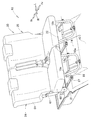
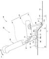
- FIG. 1 is a perspective view showing a vehicle seat device according to the present invention. It is a side view which shows the vehicle seat apparatus of FIG. It is a disassembled perspective view which shows the vehicle seat apparatus of FIG. (A) is a perspective view which shows the right slide rail of FIG. 3, (b) is a perspective view which shows the state which slidably moved the movable base of (a) ahead of the vehicle body. It is a perspective view which shows the right sheet
- the vehicle 10 includes a vehicle body floor 11 that forms a floor portion of the vehicle 10, and a vehicle seat device 20 provided on the vehicle body floor 11.
- the vehicle seat device 20 is a rearmost seat provided at the rear portion of the vehicle body floor 11.
- the vehicle body floor 11 is inclined in an upward slope from the rear end portion 12a of the low stage floor 12 to the rear of the vehicle body, and the low stage floor 12 that is positioned substantially horizontally and positioned in front of the vehicle seat device 20. It has an inclined floor 14 and a high floor 15 projecting substantially horizontally from the rear end portion 14a of the inclined floor 14 toward the rear of the vehicle body.
- the high floor 15 is provided on the vehicle rear side of the low floor 12 so as to be connected to the rear end portion 12 a of the low floor 12 via the inclined floor 14.
- the lower floor 12 has a storage position 13 in front of the vehicle body.
- the storage position 13 is a position for storing the vehicle seat device 20 folded in the storage mode (see FIG. 11) with the seat back 61 of the vehicle seat device 20 tilted forward.
- the high floor 15 is disposed at a position higher than the low floor 12 by the height dimension H1.
- the vehicle seat device 20 includes a right slide rail 21 provided on the right half 15 a of the high floor 15, a left slide rail 22 provided on the left half 15 b of the high floor 15, and the right slide rail 21.
- a supported right seat 24 and a left seat 25 supported by the left slide rail 22 are provided.
- the right seat 24 is supported on the vehicle body floor 11 via the right slide rail 21 so as to be movable in the vehicle front-rear direction (hereinafter referred to as slide movement).
- the left seat 25 is supported on the vehicle body floor 11 via the left slide rail 22 so as to be slidable in the vehicle front-rear direction.
- the right slide rail 21 and the left slide rail 22 are substantially bilaterally symmetric members.
- the right slide rail 21 will be described in detail and description of the left slide rail 22 will be omitted.
- the right seat 24 and the left seat 25 are substantially bilaterally symmetric members.
- the right seat 24 will be described in detail and the description of the left seat 25 will be omitted.
- the right slide rail 21 includes a fixed rail 27 that is fixed to the high floor 15 so as to extend in the longitudinal direction of the vehicle body, and a movable base 31 that is slidably provided on the fixed rail 27. And.
- the fixed rail 27 includes an inner rail 28 provided on the center side in the vehicle width direction of the right half 15a of the high floor 15 and an outer side provided on the outer side in the vehicle width of the right half 15a of the high floor 15.
- Rail 29 is provided.
- the inner rail 28 and the outer rail 29 extend in the vehicle longitudinal direction parallel to each other at a predetermined interval in the vehicle width direction.
- a movable base 31 is slidably supported on the inner rail 28 and the outer rail 29.
- the inner rail 28 and the outer rail 29 are substantially bilaterally symmetric members.
- the movable base 31 includes a movable portion 32 that is slidably supported on the inner rail 28 and the outer rail 29, a seat back support portion 33 provided on the movable portion 32, and a link support portion 34 provided on the movable portion 32. And.
- the movable part 32 has a base body 36 formed in a substantially rectangular shape in plan view, and an inner slider 37 and an outer slider 38 are provided on the back surface 36a (see FIG. 2) of the base body 36.
- the inner slider is slidably supported on the inner rail 28, and the outer slider is slidably supported on the outer rail 29.
- the movable portion 32 is supported so as to be slidable in the longitudinal direction of the vehicle body along the inner rail 28 and the outer rail 29.
- a seat back support portion 33 is provided on the upper surface 36b of the base body 36 (the upper surface of the slide rail) and at the approximate center 36c in the vehicle body front-rear direction.
- an inner back support portion 41 and an outer back support portion 42 are provided on the same straight line in the vehicle width direction.
- the seat back 61 of the vehicle seat device 20 can be rotated in the longitudinal direction of the vehicle body via the back support shaft 44 (see FIG. 2) to the inner back support portion 41 and the outer back support portion 42 (that is, the seat back support portion 33). It is supported.
- the link support part 34 is provided in the front part 36d of the base main body 36.
- the link support part 34 includes an inclined support part 46 whose base part 47 is provided on the front part 36 d of the base body 36, and an engaging part 51 provided on a support part 49 of the inclined support part 46.
- the inclined support portion 46 is a rear portion 36a (see FIG. 2) of the front portion 36d of the base main body 36, a base portion 47 provided at the center in the vehicle width direction, and the vehicle body along the inclined floor 14 from the front end of the base portion 47. It has the extension part 48 (refer also FIG. 6) inclined in the downward slope toward the front, and the support part 49 provided in the front-end
- the extension portion 48 is disposed on the vehicle body front side of the inclined floor 14. Moreover, the support part 49 is arrange
- a locking portion 51 is fixed to the surface of the support portion 49 with a fastening member 54 such as a bolt or a rivet (see also FIG. 6).
- the locking part 51 is formed of a leaf spring that can be elastically deformed.
- the locking portion 51 includes a fitting portion 52 that can store the connecting link 81 (specifically, the leg connecting portion 84) of the vehicle seat device 20, and an opening 53 that communicates with the fitting portion 52. .
- the opening 53 is formed upwardly above the fitting portion 52 and slightly smaller than the outer diameter D1 of the leg connecting portion 84.
- the leg connecting portion 84 when the leg connecting portion 84 is fitted to the fitting portion 52 of the locking portion 51, the opening 53 is pushed open by the leg connecting portion 84, and the leg connecting portion 84 is fitted from the opened opening 53.
- the portion 52 can be easily fitted.
- the leg connecting portion 84 is removed from the fitting portion 52 of the locking portion 51, the opening 53 is pushed open by the leg connecting portion 84, and the leg connecting portion 84 is fitted from the opened opening 53. Can be easily removed outside.
- the right seat 24 is supported on the movable base 31.
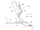
- the right seat 24 includes a seat back 61 that is provided in the seat back support portion 33 via a back support shaft 44 so as to be rotatable in the longitudinal direction of the vehicle body, and an inner and outer cushion support shaft 67 (the inner cushion support shaft is shown in the figure). And a connecting link 81 that supports the seat cushion 69 on the engaging portion 51 so as to be rotatable in the longitudinal direction of the vehicle body.
- the seat back 61 includes a seat back main body 62 that can be worn on the back of an occupant, an inner back bracket 63 that protrudes downward from an inner lower portion of the seat back main body 62, and a lower portion from an outer lower portion of the seat back main body 62 And an outer back bracket 64 that protrudes.
- An inner support hole 63 a is formed at the lower part of the inner back bracket 63, and an outer support hole 64 a is formed at the lower part of the outer back bracket 64.
- An inner back bracket 63 is disposed between the inner back support portion 41 and the outer back support portion 42, and an outer back bracket 64 is disposed at the outer end 42 a of the outer back support portion 42.
- the outer back bracket 64 and the inner back bracket 63 are rotatably supported by the seat back support portion 33 by the back support shaft 44. That is, the seat back 61 is provided on the seat back support portion 33 (that is, the movable base 31) so as to be rotatable in the longitudinal direction of the vehicle body via the back support shaft 44.
- the reclining adjustment of the seat back 61 in the vehicle longitudinal direction can be performed with the back support shaft 44 as an axis. Further, the seat back 61 can be moved forward about the back support shaft 44 until the seat back 61 is superimposed on the seat cushion 69 on the front side of the vehicle body.
- the lower end 63b of the inner back bracket 63 is provided adjacent to the upper surface 36b of the base body 36.
- a lower end (lower end of the seat back) 64 b of the outer back bracket 64 is provided below the upper surface 36 b of the base body 36.
- the back support shaft 44 can be disposed at a relatively low position P ⁇ b> 1 with respect to the high floor 15.
- the seat cushion 69 includes a cushion main body 71 on which an occupant sits, an inner cushion bracket 72 provided at the inner rear portion of the cushion main body 71, an outer cushion bracket 73 provided at the outer rear portion of the cushion main body 71, and an inner cushion bracket 72. And a reinforcing pipe 74 supported by the front portion 73a of the outer cushion bracket 73.
- a rear portion (rear portion of the seat cushion) 72b of the inner cushion bracket 72 is supported by the inner lower portion 61a of the seat back 61 via the inner cushion support shaft (not shown) so as to be rotatable in the longitudinal direction of the vehicle body.
- a rear portion (rear portion of the seat cushion) 73b of the outer cushion bracket 73 is supported on the outer lower portion 61b of the seat back 61 via the outer cushion support shaft 67 so as to be rotatable in the vehicle body front-rear direction.
- the seat cushion 69 can be rotated in the vehicle front-rear direction by the seat back 61 with the rear portion 72b of the inner cushion bracket 72 and the rear portion 73b of the outer cushion bracket 73 (specifically, the inner and outer cushion support shafts 67) as fulcrums. Is provided.
- the inner and outer cushion support shafts 67 are positioned above the inner and outer support holes 63a and 64a by a distance L1. Therefore, for example, when the right seat 24 is placed in the seating mode (the state shown in FIG. 6), the seat back 61 is moved forward with the back support shaft 44 as the center toward the front of the vehicle body. The seat cushion 69 is pushed out toward the front of the vehicle body.
- the reinforcement pipe 74 of the seat cushion 69 is formed of an inner pipe 75, an outer pipe 76, and a front connection pipe 77 in a substantially U shape in plan view.
- An inner link bracket 78 is provided at the front portion of the inner pipe 75, and an outer link bracket 79 is provided at the front portion of the outer pipe 76.
- the connecting link 81 By connecting the connecting link 81 to the inner link bracket 78 and the outer link bracket 79, the connecting link 81 is connected to the front portion 69 a of the seat cushion 69.
- the connecting link 81 has an inner leg portion 82 whose upper end portion 82a is rotatably supported by the inner link bracket 78 via a support pin 86, and an upper end portion 83a of the outer link bracket 79 via a support pin 87.
- an outer leg 83 rotatably supported in the longitudinal direction of the vehicle body, and a leg connecting portion (lower end) 84 connecting the lower end 82b of the inner leg 82 and the lower end 83b of the outer leg 83. Therefore, the connecting link 81 is supported by the inner link bracket 78 and the outer link bracket 79 via the support pins 86 and 87 so as to be rotatable in the longitudinal direction of the vehicle body.
- the inner link bracket 78 is provided at the front portion of the inner pipe 75
- the outer link bracket 79 is provided at the front portion of the outer pipe 76.
- the front part of the inner pipe 75 and the front part of the outer pipe 76 are provided in the front part 69 a of the seat cushion 69. Therefore, the connecting link 81 is supported by the front portion 69a of the seat cushion 69 so as to be rotatable in the longitudinal direction of the vehicle body.
- the leg connecting portion 84 is supported so as to be rotatable in the longitudinal direction of the vehicle body by being fitted to the fitting portion 52 of the locking portion 51.
- the opening 53 is pushed open by the leg connecting portion 84, and the leg connecting portion 84 is fitted from the opened opening 53.
- the mating portion 52 can be easily fitted.
- the leg connecting portion 84 is supported by the fitting portion 52 so as to be rotatable in the longitudinal direction of the vehicle body.
- the leg connecting portion 84 When the leg connecting portion 84 is removed from the fitting portion 52 of the locking portion 51, the opening 53 is pushed open by the leg connecting portion 84, and the leg connecting portion 84 is inserted from the opened opening 53. Can be easily removed outside.
- the leg connecting portion 84 (the connecting link 81) is supported by the locking portion 51 so as to be rotatable in the longitudinal direction of the vehicle body, and is detachably supported from the locking portion 51.
- the leg connecting portion 84 of the connecting link 81 is fitted (supported) to the fitting portion 52 of the locking portion 51. Therefore, the front portion 69a of the seat cushion 69 is supported by the connecting link 81, and the seat cushion 69 is held at the seating position P2.
- the leg connecting portion 84 is detachably supported by the locking portion 51. Therefore, the seat cushion 69 can be flipped up to the seat back 61 by removing the leg connecting portion 84 from the locking portion 51 (see FIG. 8B).
- the connecting link 81 is supported so as to be rotatable in the longitudinal direction of the vehicle body with the leg connecting portion 84 as an axis. ing. Further, a connecting link 81 is supported on the front portion 69a of the seat cushion 69 so as to be rotatable in the longitudinal direction of the vehicle body. Therefore, the front portion 69a of the seat cushion 69 is supported by the connecting link 81 so as to be movable in the longitudinal direction of the vehicle body in a state where the leg connecting portion 84 is fitted to the fitting portion 52 of the locking portion 51.
- the seat cushion 69 can be smoothly moved toward the front of the vehicle body by the seat back 61.
- the right seat 24 is slid in the front-rear direction of the vehicle body with the right seat 24 placed in the seating mode
- the seat cushion 69 is placed at the seating position P2.
- the seat back 61 is supported on the base body 36 via the seat back support portion 33 (see FIG. 3) and the back support shaft 44.
- the seat cushion 69 is supported by the seat back 61 via the inner and outer cushion support shafts 67 and supported by the locking portion 51 via the connecting link 81. That is, the right seat 24 (the seat back 61 and the seat cushion 69) is supported by the movable base 31.
- the right seat 24 in the seating mode can be slid along the fixed rail 27 in the front direction of the vehicle body (in the direction of arrow B) together with the movable base 31. Furthermore, the seating mode right seat 24 can be slid along the fixed rail 27 along with the movable base 31 in the vehicle body rearward direction (arrow C direction).
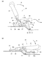
- FIG. 8A in a state where the right seat 24 is disposed in the seating mode, the seat cushion 69 is lifted upward as indicated by an arrow D with the inner and outer cushion support shafts 67 as axes.
- the leg connecting portion 84 of the connecting link 81 can be removed from the locking portion 51 by lifting the seat cushion 69.
- the seat cushion 69 can be flipped up to the seat back 61 as indicated by an arrow E by removing the leg connecting portion 84 from the locking portion 51.
- the right seat 24 is placed in the jump-up mode (chip-up mode).
- the connecting link 81 is fixed to the bottom 69b of the seat cushion 69 with a locking member (not shown).
- the seat back 61 is supported by the base body 36 via the seat back support part 33 (see FIG. 3) and the back support shaft 44 in a state where the right seat 24 is disposed in the jumping mode. Further, the seat cushion 69 is supported on the seat back 61 via the inner and outer cushion support shafts 67. That is, the seat back 61 and the seat cushion 69 are supported by the movable base 31.
- the right seat 24 in the jumping mode can be slid along the fixed rail 27 together with the movable base 31 in the vehicle body front direction (arrow F direction). Further, the right seat 24 in the jumping mode can be slid along the fixed rail 27 together with the movable base 31 in the vehicle body rearward direction (arrow G direction).
- FIG. 10A in the state where the right seat 24 is disposed in the seating mode, the seat back 61 is moved forward as indicated by an arrow H toward the front of the vehicle body with the back support shaft 44 as the center.
- the seat cushion 69 is pushed out as indicated by an arrow I toward the front of the vehicle body by the seat back 61 (specifically, the inner and outer cushion support shafts 67).
- the connecting link 81 rotates as indicated by the arrow J toward the front of the vehicle body with the leg connecting portion 84 fitted to the fitting portion 52 of the locking portion 51 as the center.
- the connecting link 81 By rotating the connecting link 81 toward the front of the vehicle body, the seat cushion 69 can be smoothly moved as indicated by an arrow K toward the front of the vehicle body and downward.
- the seat back 61 is overlaid on the seat cushion 69 by moving the seat back 61 forward and moving the seat cushion 69 forward and downward.
- the connecting link 81 is folded to the bottom 69b side of the seat cushion 69.
- the seat back 61 is superimposed on the seat cushion 69, whereby the right seat 24 is folded into the storage mode (dive down mode).
- the seat back 61 With the right seat 24 disposed in the retracted mode and the right seat 24 disposed in the seating mode, the seat back 61 is mounted on the base body via the seat back support portion 33 (see FIG. 3) and the back support shaft 44. 36. Further, the seat cushion 69 is supported by the seat back 61 via the inner and outer cushion support shafts 67 and supported by the locking portion 51 via the connecting link 81. That is, the right seat 24 (the seat back 61 and the seat cushion 69) is supported by the movable base 31.
- the right seat 24 in the storage mode can be slid along the fixed rail 27 to the storage position 13 of the lower floor 12 along the movable rail 31 as indicated by an arrow L in the front direction of the vehicle body.
- the convenience of the right seat 24 can be enhanced by sliding the right seat 24 folded in the storage mode to the storage position 13.
- the right seat 24 at the storage position 13 can be slid in the rear direction of the vehicle body along the fixed rail 27 according to the application.
- the lower end 64 b of the outer back bracket 64 is provided below the upper surface 36 b of the base body 36.
- the back support shaft 44 can be disposed at a relatively low position P1 with respect to the high floor 15.
- the right sheet 24 folded in the storage mode can be slid to the storage position 13, and the height dimension H3 of the right sheet 24 in the storage mode can be kept small. Thereby, the convenience of the right seat 24 folded into the storage mode can be further enhanced.
- the vehicle seat device according to the present invention is not limited to the above-described embodiments, and can be changed or improved as appropriate.
- the vehicle seat device 20 has been described as the last seat provided at the rear portion of the vehicle body floor 11, but the present invention is not limited to this, and a driver seat or passenger seat provided at the front portion of the vehicle body floor 11 is used. It is also possible to apply to other sheets such as a ja sheet.
- vehicle vehicle body floor, low floor, high floor, vehicle seat device, left and right slide rails, left and right seats, fixed rail, inner and outer rails, movable base, seat back, inner
- the shape and configuration of the outer back bracket, the lower end of the inner and outer back brackets, the seat cushion, the front part of the seat cushion, the rear part of the inner and outer cushion bracket, the connecting link and the leg connecting part are not limited to those illustrated. It can be changed as appropriate.
- the present invention is suitable for application to an automobile including a vehicle seat device in which a seat is provided on a vehicle body floor via a slide rail so as to be movable in the longitudinal direction of the vehicle body.
Landscapes
- Engineering & Computer Science (AREA)
- Aviation & Aerospace Engineering (AREA)
- Transportation (AREA)
- Mechanical Engineering (AREA)
- Seats For Vehicles (AREA)
Abstract
Description
このため、折り畳んだシートの高さをフロアに対して低く抑えることが難しい。
具体的には、車両用シート装置は、フロアの下方にロアフロアを設けることにより、フロアおよびロアフロアが壁部で連結され、フロアおよび壁部にスライドレールが設けられている。よって、壁部に設けられたスライドレール(以下、鉛直レールという)は上下方向に延出されている。
このため、格納モードに折り畳んだシートを車体前方に移動させて利便性を高めるシートの実用化が望まれていた。
図1、図2に示すように、車両10は、車両10の床部を形成する車体フロア11と、車体フロア11に設けられた車両用シート装置20とを備えている。
車両用シート装置20は、車体フロア11の後部に設けられた最後部のシートである。
低段フロア12は、車体前方に収納位置13を有する。収納位置13は、車両用シート装置20のシートバック61が前倒しされ、格納モード(図11参照)に折り畳まれた車両用シート装置20を収納する位置である。
高段フロア15は、低段フロア12に対して高さ寸法H1だけ高い位置に配置されている。
左シート25は、左スライドレール22を介して車体フロア11に車両前後方向にスライド移動可能に支持されている。
また、右シート24および左シート25は略左右対称の部材であり、以下右シート24について詳説して左シート25の説明を省略する。
内側レール28および外側レール29は、車幅方向に所定間隔をおいて互いに平行に車体前後方向に向けて延出されている。
内側レール28および外側レール29は、略左右対称の部材である。
可動ベース31は、内側レール28および外側レール29にスライド移動可能に支持された可動部32と、可動部32に設けられたシートバック支持部33と、可動部32に設けられたリンク支持部34とを備えている。
内側バック支持部41および外側バック支持部42(すなわち、シートバック支持部33)にバック支持軸44(図2参照)を介して車両用シート装置20のシートバック61が車体前後方向に回転可能に支持されている。
リンク支持部34が低段フロア12に対して非接触状態に配置されることにより、可動ベース31を固定レール27に沿って車体前後方向に円滑にスライド移動させることができる。
開口部53は、嵌合部52の上方に上向きで、かつ、脚連結部84の外径D1より僅かに小さく形成されている。
また、係止部51の嵌合部52から脚連結部84を外す際には、開口部53を脚連結部84で押し開け、押し開けた開口部53から脚連結部84を嵌合部52の外側に容易に外すことができる。
右シート24は、シートバック支持部33にバック支持軸44を介して車体前後方向に回転可能に設けられたシートバック61と、シートバック61に内外のクッション支持軸67(内クッション支持軸は図示せず)を介して回転可能に支持されたシートクッション69と、シートクッション69を係止部51に車体前後方向に回転可能に支持する連結リンク81とを備えている。
この状態において、シートバック支持部33に外側バックブラケット64および内側バックブラケット63がバック支持軸44で回転可能に支持される。すなわち、シートバック61は、シートバック支持部33(すなわち、可動ベース31)にバック支持軸44を介して車体前後方向に回転可能に設けられている。
よってバック支持軸44を高段フロア15に対して比較的低い位置P1に配置できる。これにより、右シート24が折り畳まれた格納モードにおいて、格納モードに折り畳まれた右シート24の高さH3(図11参照)を低く抑えることができる。
よって、シートクッション69が、内側クッションブラケット72の後部72bおよび外側クッションブラケット73の後部73b(具体的には、内外側のクッション支持軸67)を支点にしてシートバック61に車体前後方向へ回転可能に設けられている。
よって、例えば、右シート24が着座モード(図6に示す状態)に配置された状態で、シートバック61をバック支持軸44を中心にして車体前方に向けて前倒しすることにより、シートバック61でシートクッション69が車体前方に向けて押し出される。
連結リンク81は、上端部82aが内側リンクブラケット78に支持ピン86を介して車体前後方向に回転可能に支持された内側脚部82と、上端部83aが外側リンクブラケット79に支持ピン87を介して車体前後方向に回転可能に支持された外側脚部83と、内側脚部82の下端部82bおよび外側脚部83の下端部83bを連結する脚連結部(下端部)84とを有する。
よって、連結リンク81は、内側リンクブラケット78および外側リンクブラケット79に各支持ピン86,87を介して車体前後方向に回転可能に支持されている。
よって、連結リンク81は、シートクッション69の前部69aに車体前後方向に回転可能に支持されている。
ここで、脚連結部84を係止部51の嵌合部52に嵌合する際には、開口部53を脚連結部84で押し開け、押し開けた開口部53から脚連結部84を嵌合部52に容易に嵌合できる。
嵌合部52に脚連結部84が嵌合されることにより、脚連結部84が嵌合部52に車体前後方向に回転可能に支持される。
すなわち、脚連結部84(連結リンク81)は、係止部51によって車体前後方向に回転可能に支持され、かつ、係止部51から着脱可能に支持される。
また、脚連結部84は、係止部51に着脱自在に支持されている。よって、脚連結部84を係止部51から取り外すことにより、シートクッション69をシートバック61まで跳ね上げることができる(図8(b)参照)。
さらに、シートクッション69の前部69aに連結リンク81が車体前後方向に回転可能に支持されている。
よって、係止部51の嵌合部52に脚連結部84が嵌合された状態において、シートクッション69の前部69aが連結リンク81により車体前後方向に移動可能に支持されている。
これにより、右シート24を格納モード(図10(b)参照)に折り畳む際に、シートクッション69をシートバック61で車体前方に向けて円滑に移動させることができる。
図7(a)に示すように、右シート24が着座モードに配置されることにより、シートクッション69が着座位置P2に配置される。
右シート24が着座モードに配置された状態で、シートバック61がシートバック支持部33(図3参照)およびバック支持軸44を介してベース本体36に支持されている。さらに、シートクッション69が内外のクッション支持軸67を介してシートバック61に支持されるとともに連結リンク81を介して係止部51に支持されている。
すなわち、右シート24(シートバック61およびシートクッション69)が可動ベース31に支持されている。
さらに、着座モードの右シート24を可動ベース31とともに、固定レール27に沿って車体後方向(矢印C方向)にスライド移動することができる。
図8(a)に示すように、右シート24が着座モードに配置された状態で、シートクッション69を内外のクッション支持軸67を軸にして上方に矢印Dの如く持ち上げる。シートクッション69を持ち上げることにより連結リンク81の脚連結部84を係止部51から取り外すことができる。
ここで、連結リンク81がシートクッション69の底部69bに係止部材(図示せず)で固定される。
すなわち、シートバック61およびシートクッション69が可動ベース31に支持される。
図10(a)に示すように、右シート24が着座モードに配置された状態で、シートバック61をバック支持軸44を中心にして車体前方に向けて矢印Hの如く前倒しする。
シートバック61を前倒しすることにより、シートバック61(具体的には、内外のクッション支持軸67)でシートクッション69が車体前方に向けて矢印Iの如く押し出される。
よって、係止部51の嵌合部52に嵌合された脚連結部84を中心にして連結リンク81が車体前方に向けて矢印Jの如く回転する。連結リンク81が車体前方に向けて回転することにより、シートクッション69を車体前方で、かつ下方に向けて矢印Kの如く円滑に移動させることができる。
同時に、連結リンク81がシートクッション69の底部69b側に折り畳まれる。
このように、シートバック61がシートクッション69の上に重ね合わされることにより、右シート24が格納モード(ダイブダウンモード)に折り畳まれる。
すなわち、右シート24(シートバック61およびシートクッション69)が可動ベース31に支持されている。
このように、格納モードに折り畳んだ右シート24を収納位置13までスライド移動することにより右シート24の利便性を高めることができる。また、収納位置13の右シート24を用途に応じて固定レール27に沿って車体後方向にスライド移動することができる。
例えば、前記実施例では、車両用シート装置20を車体フロア11の後部に設けた最後部のシートとして説明したが、これに限るものではなく、車体フロア11の前部に設けたドライバシートやパッセンジャシートなどの他のシートに適用することも可能である。
Claims (2)
- 車体フロアの低段フロアに連なるように高段フロアが車両後方に設けられ、該高段フロアにスライドレールの固定レールが車体前後方向に延びるように固定され、該固定レールに可動ベースが移動可能に設けられ、該可動ベースにシートが設けられることにより、該シートが前記スライドレールを介して前記車体フロアに車両前後方向に移動可能に支持された車両用シート装置であって、
前記シートは、
前記可動ベースに車体前後方向に回転可能に設けられたシートバックと、
該シートバックに後部が支持されることにより、前記後部を支点にして車体前後方向に回転可能に設けられたシートクッションと、
該シートクッションの前部を前記可動ベースに車体前後方向に移動可能に支持し、かつ、下端部が前記可動ベースに着脱自在に支持された連結リンクと、を備え、
前記シートバックが前倒しされて前記シートクッションの上に重ね合わされた状態で、前記低段フロアの収納位置まで移動可能としたことを特徴とする車両用シート装置。 - 前記シートバックの下端が前記スライドレールの上面よりも下側に設けられている、請求項1記載の車両用シート装置。
Priority Applications (4)
| Application Number | Priority Date | Filing Date | Title |
|---|---|---|---|
| EP14782828.9A EP2985176B1 (en) | 2013-04-12 | 2014-04-11 | Vehicular seat device |
| JP2015511311A JP5961322B2 (ja) | 2013-04-12 | 2014-04-11 | 車両用シート装置 |
| CN201480020996.0A CN105121222B (zh) | 2013-04-12 | 2014-04-11 | 车辆用座椅装置 |
| US14/780,066 US9643519B2 (en) | 2013-04-12 | 2014-04-11 | Vehicular seat device |
Applications Claiming Priority (2)
| Application Number | Priority Date | Filing Date | Title |
|---|---|---|---|
| JP2013-083824 | 2013-04-12 | ||
| JP2013083824 | 2013-04-12 |
Publications (1)
| Publication Number | Publication Date |
|---|---|
| WO2014168233A1 true WO2014168233A1 (ja) | 2014-10-16 |
Family
ID=51689634
Family Applications (1)
| Application Number | Title | Priority Date | Filing Date |
|---|---|---|---|
| PCT/JP2014/060472 WO2014168233A1 (ja) | 2013-04-12 | 2014-04-11 | 車両用シート装置 |
Country Status (5)
| Country | Link |
|---|---|
| US (1) | US9643519B2 (ja) |
| EP (1) | EP2985176B1 (ja) |
| JP (1) | JP5961322B2 (ja) |
| CN (1) | CN105121222B (ja) |
| WO (1) | WO2014168233A1 (ja) |
Cited By (10)
| Publication number | Priority date | Publication date | Assignee | Title |
|---|---|---|---|---|
| US20150021958A1 (en) * | 2013-07-19 | 2015-01-22 | Tachi-S Co., Ltd. | Vehicle seat |
| WO2016076318A1 (ja) * | 2014-11-11 | 2016-05-19 | テイ・エス テック株式会社 | 車両用シート |
| JP2016088483A (ja) * | 2014-11-11 | 2016-05-23 | テイ・エス テック株式会社 | 車両用シート |
| JP2016088481A (ja) * | 2014-11-11 | 2016-05-23 | テイ・エス テック株式会社 | 車両用シート |
| JP2016088480A (ja) * | 2014-11-11 | 2016-05-23 | テイ・エス テック株式会社 | 車両用シート |
| JP2016088477A (ja) * | 2014-11-11 | 2016-05-23 | テイ・エス テック株式会社 | 車両用シート |
| JP2016088479A (ja) * | 2014-11-11 | 2016-05-23 | テイ・エス テック株式会社 | 車両用シート |
| JP2019001464A (ja) * | 2018-10-10 | 2019-01-10 | テイ・エス テック株式会社 | 車両用シート |
| JP2019034733A (ja) * | 2018-10-10 | 2019-03-07 | テイ・エス テック株式会社 | 車両用シート |
| US10759304B2 (en) | 2017-08-30 | 2020-09-01 | Ts Tech Co., Ltd. | Conveyance seat |
Families Citing this family (8)
| Publication number | Priority date | Publication date | Assignee | Title |
|---|---|---|---|---|
| US9884571B2 (en) * | 2013-06-14 | 2018-02-06 | Ts Tech Co., Ltd. | Vehicular seat |
| JP6262575B2 (ja) * | 2014-03-13 | 2018-01-17 | テイ・エス テック株式会社 | 車両用シート |
| JP6554371B2 (ja) * | 2015-09-16 | 2019-07-31 | 株式会社タチエス | 車両用シート |
| US10689120B2 (en) * | 2016-08-29 | 2020-06-23 | Textron Innovations, Inc. | Stowable reversible seat |
| WO2019164193A1 (ko) * | 2018-02-20 | 2019-08-29 | 주식회사 대유홀딩스 | 차량용 시트장치 |
| JP7017134B2 (ja) * | 2018-10-09 | 2022-02-08 | トヨタ自動車株式会社 | 車両用シート |
| US11548419B2 (en) * | 2019-06-18 | 2023-01-10 | Lear Corporation | Seat assembly |
| JP7111781B2 (ja) * | 2020-08-26 | 2022-08-02 | 本田技研工業株式会社 | 車両用シート |
Citations (5)
| Publication number | Priority date | Publication date | Assignee | Title |
|---|---|---|---|---|
| JPH0393233A (ja) | 1989-09-05 | 1991-04-18 | Nec Corp | 半導体装置の製造方法 |
| JP2004249109A (ja) * | 2003-02-19 | 2004-09-09 | Faurecia Sieges D'automobile | 折り畳みシートおよびこのようなシートを含む乗物 |
| JP2005280501A (ja) | 2004-03-30 | 2005-10-13 | Tachi S Co Ltd | 格納シート |
| JP2005297834A (ja) * | 2004-04-14 | 2005-10-27 | Toyota Motor Corp | 車両用可倒シート構造 |
| JP2006321483A (ja) * | 2005-05-18 | 2006-11-30 | Faurecia Sieges D'automobile | 全体の長さを制限するための自動車座席の構造 |
Family Cites Families (21)
| Publication number | Priority date | Publication date | Assignee | Title |
|---|---|---|---|---|
| US6099072A (en) * | 1997-10-15 | 2000-08-08 | Lear Corporation | Floor mounting system for a collapsible vehicle seat |
| US6123380A (en) * | 1999-06-11 | 2000-09-26 | Lear Corporation | Automotive seat assembly with folding structural supports for storage in a foot well for an automotive vehicle body |
| JP3647408B2 (ja) * | 2001-10-16 | 2005-05-11 | 本田技研工業株式会社 | 車両のシート構成 |
| JP2003285674A (ja) | 2002-03-29 | 2003-10-07 | Johnson Controls Automotive Systems Corp | 乗り物用シート |
| JP3771204B2 (ja) | 2002-08-06 | 2006-04-26 | 本田技研工業株式会社 | 車両用シート構造 |
| JP3878099B2 (ja) * | 2002-09-19 | 2007-02-07 | 本田技研工業株式会社 | 車両用シート配列構造 |
| JP3860151B2 (ja) * | 2003-08-29 | 2006-12-20 | 株式会社タチエス | 車両用格納式シート |
| JP4115953B2 (ja) | 2004-02-27 | 2008-07-09 | 本田技研工業株式会社 | 車両用シート |
| US7077463B2 (en) * | 2004-04-06 | 2006-07-18 | Lear Corporation | Rear fold down cargo seat with tilt down cushion |
| US7152921B2 (en) * | 2004-08-18 | 2006-12-26 | Lear Corporation | Vehicle seat |
| FR2885087B1 (fr) | 2005-04-27 | 2008-12-19 | Peugeot Citroen Automobiles Sa | Siege repliable en au moins une position pour vehicule automobile |
| JP4673692B2 (ja) * | 2005-07-19 | 2011-04-20 | 本田技研工業株式会社 | 車両における電気機器の冷却構造 |
| CA2626557A1 (en) * | 2005-11-17 | 2007-05-24 | Intier Automotive Inc. | Over and under swing seat |
| US7240949B1 (en) | 2006-02-28 | 2007-07-10 | Daimlerchrysler Corporation | Adjustable seat assembly |
| JP4176118B2 (ja) | 2006-07-31 | 2008-11-05 | トヨタ自動車株式会社 | 車両用シート装置 |
| US7878592B2 (en) * | 2007-03-14 | 2011-02-01 | Aisin Seiki Kabushiki Kaisha | Seat apparatus for vehicle |
| JP5298457B2 (ja) * | 2007-05-18 | 2013-09-25 | アイシン精機株式会社 | 車両用シート装置 |
| DE102008050468B3 (de) * | 2008-10-04 | 2010-04-22 | Keiper Gmbh & Co. Kg | Fahrzeugsitz, insbesondere Kraftfahrzeugsitz |
| DE102009037816B3 (de) * | 2009-08-12 | 2010-10-28 | Keiper Gmbh & Co. Kg | Fahrzeugsitz, insbesondere Kraftfahrzeugsitz |
| JP5448642B2 (ja) * | 2009-08-21 | 2014-03-19 | アイシン精機株式会社 | 電動格納車両シートのロック装置 |
| CN102555859A (zh) * | 2011-12-31 | 2012-07-11 | 重庆长安汽车股份有限公司 | 折叠式汽车后排座椅 |
-
2014
- 2014-04-11 JP JP2015511311A patent/JP5961322B2/ja active Active
- 2014-04-11 US US14/780,066 patent/US9643519B2/en active Active
- 2014-04-11 WO PCT/JP2014/060472 patent/WO2014168233A1/ja active Application Filing
- 2014-04-11 CN CN201480020996.0A patent/CN105121222B/zh active Active
- 2014-04-11 EP EP14782828.9A patent/EP2985176B1/en not_active Not-in-force
Patent Citations (5)
| Publication number | Priority date | Publication date | Assignee | Title |
|---|---|---|---|---|
| JPH0393233A (ja) | 1989-09-05 | 1991-04-18 | Nec Corp | 半導体装置の製造方法 |
| JP2004249109A (ja) * | 2003-02-19 | 2004-09-09 | Faurecia Sieges D'automobile | 折り畳みシートおよびこのようなシートを含む乗物 |
| JP2005280501A (ja) | 2004-03-30 | 2005-10-13 | Tachi S Co Ltd | 格納シート |
| JP2005297834A (ja) * | 2004-04-14 | 2005-10-27 | Toyota Motor Corp | 車両用可倒シート構造 |
| JP2006321483A (ja) * | 2005-05-18 | 2006-11-30 | Faurecia Sieges D'automobile | 全体の長さを制限するための自動車座席の構造 |
Non-Patent Citations (1)
| Title |
|---|
| See also references of EP2985176A4 |
Cited By (14)
| Publication number | Priority date | Publication date | Assignee | Title |
|---|---|---|---|---|
| US20150021958A1 (en) * | 2013-07-19 | 2015-01-22 | Tachi-S Co., Ltd. | Vehicle seat |
| US9827880B2 (en) | 2013-07-19 | 2017-11-28 | Tachi-S Co., Ltd. | Vehicle seat |
| JP2016088479A (ja) * | 2014-11-11 | 2016-05-23 | テイ・エス テック株式会社 | 車両用シート |
| JP2016088481A (ja) * | 2014-11-11 | 2016-05-23 | テイ・エス テック株式会社 | 車両用シート |
| JP2016088480A (ja) * | 2014-11-11 | 2016-05-23 | テイ・エス テック株式会社 | 車両用シート |
| JP2016088477A (ja) * | 2014-11-11 | 2016-05-23 | テイ・エス テック株式会社 | 車両用シート |
| JP2016088483A (ja) * | 2014-11-11 | 2016-05-23 | テイ・エス テック株式会社 | 車両用シート |
| CN107107791A (zh) * | 2014-11-11 | 2017-08-29 | 提爱思科技股份有限公司 | 车用座椅 |
| WO2016076318A1 (ja) * | 2014-11-11 | 2016-05-19 | テイ・エス テック株式会社 | 車両用シート |
| US10427561B2 (en) | 2014-11-11 | 2019-10-01 | Ts Tech Co., Ltd. | Vehicular seat |
| CN107107791B (zh) * | 2014-11-11 | 2020-03-17 | 提爱思科技股份有限公司 | 车用座椅 |
| US10759304B2 (en) | 2017-08-30 | 2020-09-01 | Ts Tech Co., Ltd. | Conveyance seat |
| JP2019001464A (ja) * | 2018-10-10 | 2019-01-10 | テイ・エス テック株式会社 | 車両用シート |
| JP2019034733A (ja) * | 2018-10-10 | 2019-03-07 | テイ・エス テック株式会社 | 車両用シート |
Also Published As
| Publication number | Publication date |
|---|---|
| JP5961322B2 (ja) | 2016-08-02 |
| EP2985176A4 (en) | 2017-02-22 |
| CN105121222B (zh) | 2017-05-24 |
| US20160046210A1 (en) | 2016-02-18 |
| EP2985176B1 (en) | 2018-04-04 |
| CN105121222A (zh) | 2015-12-02 |
| US9643519B2 (en) | 2017-05-09 |
| JPWO2014168233A1 (ja) | 2017-02-16 |
| EP2985176A1 (en) | 2016-02-17 |
Similar Documents
| Publication | Publication Date | Title |
|---|---|---|
| JP5961322B2 (ja) | 車両用シート装置 | |
| US9056576B2 (en) | Utility vehicle | |
| US7350867B2 (en) | Vehicle seat | |
| CN102343838A (zh) | 用于车辆的座椅滑动装置 | |
| JP5609601B2 (ja) | オットマン装置 | |
| JP4622760B2 (ja) | 車両用シート装置 | |
| JP2006306251A (ja) | 自動車シート | |
| KR101690045B1 (ko) | 자동차 후석 폴딩 장치 | |
| JP2007253669A (ja) | 車両用シート装置 | |
| JP4622759B2 (ja) | 車両用シート装置 | |
| JP6318014B2 (ja) | 乗物用シート | |
| JP5078587B2 (ja) | 車両用シート | |
| JP2009035022A (ja) | 車両のシート装置 | |
| JP2007062595A (ja) | 車両用シート装置 | |
| JP2007331400A (ja) | 車両用シート装置 | |
| JP2005297632A (ja) | 車両用シート構造 | |
| JP2008081022A (ja) | 車両用シート格納構造 | |
| JP5034522B2 (ja) | 格納式シート | |
| JP3991949B2 (ja) | 車両用シート構造 | |
| JP2015140152A (ja) | 折り畳みシート | |
| JP2009101935A (ja) | 車両のシート装置 | |
| JP2012116327A (ja) | 車両用折り畳み式シート装置 | |
| JP4028455B2 (ja) | 車両用シート装置 | |
| US821910A (en) | Shifting-seat carriage. | |
| JP2007325682A (ja) | 車両用シート装置 |
Legal Events
| Date | Code | Title | Description |
|---|---|---|---|
| 121 | Ep: the epo has been informed by wipo that ep was designated in this application |
Ref document number: 14782828 Country of ref document: EP Kind code of ref document: A1 |
|
| ENP | Entry into the national phase |
Ref document number: 2015511311 Country of ref document: JP Kind code of ref document: A |
|
| WWE | Wipo information: entry into national phase |
Ref document number: 14780066 Country of ref document: US |
|
| WWE | Wipo information: entry into national phase |
Ref document number: IDP00201506399 Country of ref document: ID |
|
| NENP | Non-entry into the national phase |
Ref country code: DE |
|
| WWE | Wipo information: entry into national phase |
Ref document number: 2014782828 Country of ref document: EP |