WO2014141986A1 - 円すいころ軸受 - Google Patents
円すいころ軸受 Download PDFInfo
- Publication number
- WO2014141986A1 WO2014141986A1 PCT/JP2014/055727 JP2014055727W WO2014141986A1 WO 2014141986 A1 WO2014141986 A1 WO 2014141986A1 JP 2014055727 W JP2014055727 W JP 2014055727W WO 2014141986 A1 WO2014141986 A1 WO 2014141986A1
- Authority
- WO
- WIPO (PCT)
- Prior art keywords
- ring
- double
- roller bearing
- tapered roller
- elastic
- Prior art date
- Legal status (The legal status is an assumption and is not a legal conclusion. Google has not performed a legal analysis and makes no representation as to the accuracy of the status listed.)
- Ceased
Links
Images



Classifications
-
- F—MECHANICAL ENGINEERING; LIGHTING; HEATING; WEAPONS; BLASTING
- F16—ENGINEERING ELEMENTS AND UNITS; GENERAL MEASURES FOR PRODUCING AND MAINTAINING EFFECTIVE FUNCTIONING OF MACHINES OR INSTALLATIONS; THERMAL INSULATION IN GENERAL
- F16C—SHAFTS; FLEXIBLE SHAFTS; ELEMENTS OR CRANKSHAFT MECHANISMS; ROTARY BODIES OTHER THAN GEARING ELEMENTS; BEARINGS
- F16C19/00—Bearings with rolling contact, for exclusively rotary movement
- F16C19/22—Bearings with rolling contact, for exclusively rotary movement with bearing rollers essentially of the same size in one or more circular rows, e.g. needle bearings
- F16C19/34—Bearings with rolling contact, for exclusively rotary movement with bearing rollers essentially of the same size in one or more circular rows, e.g. needle bearings for both radial and axial load
- F16C19/38—Bearings with rolling contact, for exclusively rotary movement with bearing rollers essentially of the same size in one or more circular rows, e.g. needle bearings for both radial and axial load with two or more rows of rollers
- F16C19/383—Bearings with rolling contact, for exclusively rotary movement with bearing rollers essentially of the same size in one or more circular rows, e.g. needle bearings for both radial and axial load with two or more rows of rollers with tapered rollers, i.e. rollers having essentially the shape of a truncated cone
- F16C19/388—Bearings with rolling contact, for exclusively rotary movement with bearing rollers essentially of the same size in one or more circular rows, e.g. needle bearings for both radial and axial load with two or more rows of rollers with tapered rollers, i.e. rollers having essentially the shape of a truncated cone with four rows, i.e. four row tapered roller bearings
-
- F—MECHANICAL ENGINEERING; LIGHTING; HEATING; WEAPONS; BLASTING
- F16—ENGINEERING ELEMENTS AND UNITS; GENERAL MEASURES FOR PRODUCING AND MAINTAINING EFFECTIVE FUNCTIONING OF MACHINES OR INSTALLATIONS; THERMAL INSULATION IN GENERAL
- F16C—SHAFTS; FLEXIBLE SHAFTS; ELEMENTS OR CRANKSHAFT MECHANISMS; ROTARY BODIES OTHER THAN GEARING ELEMENTS; BEARINGS
- F16C19/00—Bearings with rolling contact, for exclusively rotary movement
- F16C19/52—Bearings with rolling contact, for exclusively rotary movement with devices affected by abnormal or undesired conditions
-
- F—MECHANICAL ENGINEERING; LIGHTING; HEATING; WEAPONS; BLASTING
- F16—ENGINEERING ELEMENTS AND UNITS; GENERAL MEASURES FOR PRODUCING AND MAINTAINING EFFECTIVE FUNCTIONING OF MACHINES OR INSTALLATIONS; THERMAL INSULATION IN GENERAL
- F16C—SHAFTS; FLEXIBLE SHAFTS; ELEMENTS OR CRANKSHAFT MECHANISMS; ROTARY BODIES OTHER THAN GEARING ELEMENTS; BEARINGS
- F16C33/00—Parts of bearings; Special methods for making bearings or parts thereof
- F16C33/72—Sealings
- F16C33/76—Sealings of ball or roller bearings
- F16C33/768—Sealings of ball or roller bearings between relatively stationary parts, i.e. static seals
-
- F—MECHANICAL ENGINEERING; LIGHTING; HEATING; WEAPONS; BLASTING
- F16—ENGINEERING ELEMENTS AND UNITS; GENERAL MEASURES FOR PRODUCING AND MAINTAINING EFFECTIVE FUNCTIONING OF MACHINES OR INSTALLATIONS; THERMAL INSULATION IN GENERAL
- F16C—SHAFTS; FLEXIBLE SHAFTS; ELEMENTS OR CRANKSHAFT MECHANISMS; ROTARY BODIES OTHER THAN GEARING ELEMENTS; BEARINGS
- F16C35/00—Rigid support of bearing units; Housings, e.g. caps, covers
- F16C35/04—Rigid support of bearing units; Housings, e.g. caps, covers in the case of ball or roller bearings
- F16C35/06—Mounting or dismounting of ball or roller bearings; Fixing them onto shaft or in housing
- F16C35/063—Fixing them on the shaft
-
- F—MECHANICAL ENGINEERING; LIGHTING; HEATING; WEAPONS; BLASTING
- F16—ENGINEERING ELEMENTS AND UNITS; GENERAL MEASURES FOR PRODUCING AND MAINTAINING EFFECTIVE FUNCTIONING OF MACHINES OR INSTALLATIONS; THERMAL INSULATION IN GENERAL
- F16J—PISTONS; CYLINDERS; SEALINGS
- F16J15/00—Sealings
- F16J15/16—Sealings between relatively-moving surfaces
- F16J15/32—Sealings between relatively-moving surfaces with elastic sealings, e.g. O-rings
- F16J15/3204—Sealings between relatively-moving surfaces with elastic sealings, e.g. O-rings with at least one lip
- F16J15/3208—Sealings between relatively-moving surfaces with elastic sealings, e.g. O-rings with at least one lip provided with tension elements, e.g. elastic rings
- F16J15/3212—Sealings between relatively-moving surfaces with elastic sealings, e.g. O-rings with at least one lip provided with tension elements, e.g. elastic rings with metal springs
-
- F—MECHANICAL ENGINEERING; LIGHTING; HEATING; WEAPONS; BLASTING
- F16—ENGINEERING ELEMENTS AND UNITS; GENERAL MEASURES FOR PRODUCING AND MAINTAINING EFFECTIVE FUNCTIONING OF MACHINES OR INSTALLATIONS; THERMAL INSULATION IN GENERAL
- F16J—PISTONS; CYLINDERS; SEALINGS
- F16J15/00—Sealings
- F16J15/16—Sealings between relatively-moving surfaces
- F16J15/32—Sealings between relatively-moving surfaces with elastic sealings, e.g. O-rings
- F16J15/324—Arrangements for lubrication or cooling of the sealing itself
-
- F—MECHANICAL ENGINEERING; LIGHTING; HEATING; WEAPONS; BLASTING
- F16—ENGINEERING ELEMENTS AND UNITS; GENERAL MEASURES FOR PRODUCING AND MAINTAINING EFFECTIVE FUNCTIONING OF MACHINES OR INSTALLATIONS; THERMAL INSULATION IN GENERAL
- F16C—SHAFTS; FLEXIBLE SHAFTS; ELEMENTS OR CRANKSHAFT MECHANISMS; ROTARY BODIES OTHER THAN GEARING ELEMENTS; BEARINGS
- F16C2322/00—Apparatus used in shaping articles
- F16C2322/12—Rolling apparatus, e.g. rolling stands, rolls
-
- F—MECHANICAL ENGINEERING; LIGHTING; HEATING; WEAPONS; BLASTING
- F16—ENGINEERING ELEMENTS AND UNITS; GENERAL MEASURES FOR PRODUCING AND MAINTAINING EFFECTIVE FUNCTIONING OF MACHINES OR INSTALLATIONS; THERMAL INSULATION IN GENERAL
- F16C—SHAFTS; FLEXIBLE SHAFTS; ELEMENTS OR CRANKSHAFT MECHANISMS; ROTARY BODIES OTHER THAN GEARING ELEMENTS; BEARINGS
- F16C33/00—Parts of bearings; Special methods for making bearings or parts thereof
- F16C33/30—Parts of ball or roller bearings
- F16C33/58—Raceways; Race rings
- F16C33/583—Details of specific parts of races
- F16C33/586—Details of specific parts of races outside the space between the races, e.g. end faces or bore of inner ring
Definitions
- This invention relates to a tapered roller bearing having a double row inner ring.
- the outer ring is fitted into the housing with a tight fit, and the double-row inner ring is fitted into the roll shaft with a loose fit.
- creep is likely to occur in the double-row inner ring, and there is a high possibility that creep wear will occur at the contact portion between the inner diameter surface of the double-row inner ring and the outer diameter surface of the roll shaft.
- a spiral groove is formed on the inner surface of the double row inner ring, and a lubricant is accommodated in the spiral groove so that a contact portion between the inner surface of the inner ring and the outer surface of the roll shaft is formed.
- measures are taken to suppress creep wear by sliding the lubricant under lubrication.
- the lubricant easily scatters to the outside, and the creep wear cannot be suppressed over a long period of time due to the exhaustion of the lubricant.
- a circumferential groove is formed on the outer diameter surface of the portion where the bearing of the rotating shaft is fitted, an elastic ring is incorporated in the circumferential groove, and the elastic ring is connected to the inner diameter surface of the bearing inner ring. It is made to contact elastically and to prevent creep of the inner ring with respect to the rotating shaft by the frictional force.
- the elastic ring when a large radial load is applied to the roll shaft, the elastic ring is elastically deformed, and the inner ring inner diameter surface and the outer diameter surface of the roll shaft are partly in the circumferential direction. In this case, creep occurs upon contact with each other, and creep wear at the contact portion cannot be effectively prevented, and there are still points to be improved.
- An object of the present invention is to effectively prevent creep wear between a double-row inner ring that is fitted with a clearance fit with a rotary shaft such as a roll shaft in a rolling mill and the rotary shaft. To provide tapered roller bearings.
- a tapered roller bearing having at least one double-row inner ring and rotatably supporting the rotary shaft by fitting the double-row inner ring to the rotary shaft as a clearance fit.
- a pair of ring grooves are provided at both ends of the inner diameter surface of the double row inner ring, and an elastic ring elastically contacting the outer diameter surface of the rotating shaft is incorporated in each of the pair of ring grooves.
- a sealed fitting gap is formed between the inner diameter surface and the outer diameter surface of the rotary shaft, and a configuration is adopted in which the lubricant is accommodated in the fitting gap.
- a pair of ring grooves on the inner surface of the double-row inner ring are provided, and an elastic ring is incorporated in each of the ring grooves and brought into elastic contact with the outer surface of the rotating shaft, whereby the outer surface of the rotating shaft.
- the generation of creep can be prevented by the elastic contact of the pair of elastic rings with respect to. Even if creep occurs, the lubricant is accommodated in a sealed fitting gap formed between the pair of elastic rings, so that the double-row inner ring and the rotating shaft do not slip under the lubrication of the lubricant. Will occur, and no creep wear will occur.
- the tapered roller bearing may be a double-row tapered roller bearing made up of a single double-row inner ring, or a four-row tapered roller made up of two double-row inner rings arranged in the axial direction with their side faces butted. It may be a bearing.
- the number of parts is reduced by making the ring groove formed on the butt end side of the two double-row inner rings common across the butt ends of the two double-row inner rings.
- the assembly can be facilitated.
- the elastic ring forming the sealing fitting gap may be made of a rubber ring or a resin ring. Further, it may be formed of a metal ring having a circular cross section.
- the elastic ring consists of a rubber ring or a resin ring, it will be difficult to maintain its shape when the diameter is increased, and it will be difficult to maintain the shape. It is possible to inhibit.
- a cored bar is inserted inside, or the cross-sectional shape is an annular shape, and the diameter is expanded into a hollow portion from a separation portion formed in a part of the circumferential direction of the annular cross section. It is preferable to insert a ring-shaped coil spring that imparts an elastic force in the direction so as to enhance the shape retention and prevent the incorporation.
- the elastic ring can be prevented from falling out of the ring groove, and a stable assembled state can be obtained. .
- the elastic ring has a rectangular cross-section with a thin cylindrical part on the outer peripheral part of one side surface that is pressed against the inner surface of the peripheral wall of the ring groove by the resilience elasticity of the snap ring incorporated in the ring groove in a reduced diameter state. If a rubber ring or a resin ring with a tapered surface formed at the intersection of the inner diameter surface and the other side that is in elastic contact with the diameter surface is used, the elastic state of the snap ring ensures a stable assembled state. Obtainable. Further, when the double-row inner ring is fitted to the rotating shaft, the tapered surface is contact-guided at the outer peripheral portion of the end surface of the rotating shaft, so that the double-row inner ring can be smoothly fitted to the outer diameter surface of the rotating shaft.
- the occurrence of creep can be prevented by the elastic contact of the pair of elastic rings with the outer diameter surface of the rotating shaft, and even if creep occurs, it can rotate with the double-row inner ring. Since the shaft slips under the lubrication of the lubricant accommodated in the sealing fitting gap, creep wear between the double row inner ring and the rotating shaft can be effectively prevented.
- the lubricant since the lubricant is accommodated in the sealed fitting gap, the lubricant is not leaked to the outside, the lubricant can be held for a long time, and creep wear can be prevented for a long time.
- FIG. 1 shows a bearing device in which a rotating shaft 2 is supported by a four-row tapered roller bearing 10 incorporated in a housing 1.
- the four-row tapered roller bearing 10 has two double-row inner rings 11, one double-row outer ring 12a, and two single-row outer rings 12b, and the two double-row inner rings 11 face each other. It is arranged in parallel in the axial direction, and is fitted to the rotary shaft 2 by clearance fitting.
- one double-row outer ring 12a and two single-row outer rings 12b are arranged in parallel in the axial direction so that two single-row inner rings 12b are positioned on both sides in the axial direction of the single double-row outer ring 12a.
- Tapered rollers 13 are incorporated between the outer rings 12 a and 12 b and the two double-row inner rings 11. Also.
- Each of the outer rings 12 a and 12 b is an interference fit with respect to the housing 1.
- a seal holding ring 14 is attached to the outside of each of the two single-row outer rings 12b, and the bearing space is sealed by an oil seal 15 attached to the inner diameter side of each seal holding ring 14.
- Each of the two double-row inner rings 11 is formed with a pair of ring grooves 16 at both axial ends on the inner diameter surface, and an elastic ring 17 is incorporated in each of the ring grooves 16.
- an O-ring made of rubber is adopted as the elastic ring 17, but an O-ring made of resin may be adopted.
- the elastic ring 17 is in elastic contact with the outer diameter surface of the rotating shaft 2, and a sealing fitting gap is provided between the pair of elastic rings 17 between the inner diameter surface of the double row inner ring 11 and the outer diameter surface of the rotating shaft 2. 18 is formed, and the lubricant is accommodated in the fitting gap 18.
- Reference numeral 19 denotes a lubricant layer.
- the lubricant is accommodated in a sealed fitting gap 18 formed between the inner diameter surface of the double-row inner ring 11 and the outer diameter surface of the rotary shaft 2 between the pair of elastic rings 17, the creep is temporarily assumed. Even if the pair of double-row inner rings 11 are rotated with respect to the rotary shaft 2, the double-row inner rings 11 and the rotary shaft 2 slip under the lubrication of the lubricant accommodated in the hermetic fitting gap 18. Therefore, creep wear does not occur between the double-row inner ring 11 and the rotary shaft 2.
- the lubricant is accommodated in the sealed fitting gap 18, there is no inconvenience that the lubricant leaks to the outside and is exhausted, and creep wear can be prevented over a long period of time.
- FIG. 1 shows the elastic ring 17 made of an O-ring, but the elastic ring 17 is not limited to the O-ring. 2 to 7 show other examples of the elastic ring 17.
- the elastic ring 17 is a rubber ring or a resin ring having a circular cross section and having a core 20 inserted in the center thereof.
- the shape retention is excellent compared to the elastic ring in which the core metal is not inserted, and the assembled state with respect to the ring groove 16 is better. Even if it is, it ensures a circular state.
- the elastic ring 17 having a low shape retaining property
- the elastic ring 17 is deformed by its own weight in the assembled state with respect to the ring groove 16, and loosens.
- the elastic ring 17 with a cored bar as described above is excellent in shape retaining property, it is disadvantageous in that loosening occurs and the fitting of the double-row inner ring 11 is inhibited. There is no occurrence, and the double-row inner ring 11 can be smoothly fitted to the rotating shaft 2.
- the cross section is an annular shape and has a hollow portion 21, and a radial cut-off portion 22 is formed in a part of the annular cross-section in the circumferential direction.
- the elastic ring 17 is a rubber ring or a resin ring to which the coil spring 23 is inserted and an elastic force in the diameter expansion direction is applied.
- the elastic ring 17 is also excellent in shape retention due to the incorporation of the coil spring 23, and similarly to the elastic ring 17 shown in FIGS. 2 and 3, the inconvenience of hindering the fitting of the double-row inner ring 11 is caused.
- the double-row inner ring 11 can be smoothly fitted to the rotating shaft 2.
- a metal ring having an annular cross section is an elastic ring 17. Since this elastic ring 17 is also highly rigid, it has excellent shape retention, and there is no inconvenience of hindering the fitting of the double-row inner ring 11, and the double-row inner ring 11 is smoothly fitted to the rotary shaft 2. can do.
- the formed ring-shaped object is an elastic ring 17.
- the ring body 26 made of rubber or resin has a rectangular cross section, and a thin cylindrical portion 27 is provided on the outer peripheral portion of one side surface of the ring body 26, and elastic contact is made with the outer diameter surface of the rotating shaft 2 of the ring body 26.
- a ring-shaped object having a tapered surface 28 formed at the intersection of the inner diameter surface and the other side surface is used as the elastic ring 17.
- the snap ring 30 is incorporated in the ring groove 16 in a reduced diameter state, and the thin cylindrical portion is restored by the restoring elasticity of the snap ring 30. 27 is pressed against the inner surface of the peripheral wall of the ring groove 16 to secure the assembled state.
- the tapered surface 28 is formed at the intersection of the inner surface and the other surface elastically contacting the outer diameter surface of the rotating shaft 2 of the ring body 26, the double-row inner ring 11 with respect to the rotating shaft 2 is formed.
- the tapered surface 28 is contact-guided at the outer peripheral portion of the end surface of the rotating shaft 2, and the double-row inner ring 11 can be smoothly fitted to the outer diameter surface of the rotating shaft 2.
- a pair of ring grooves 16 are formed at both ends of the inner diameter surface of each of the two double-row inner rings 11, and an elastic ring 17 is incorporated in each ring groove 16.
- the ring groove 16 is formed so as to straddle the butted ends of the two double-row inner rings 11, and the ring groove 16 may be used as a common ring groove for the two double-row inner rings 11. Good.
- the number of parts is reduced by making the ring groove 16 formed on the butt end side of the two double-row inner rings 11 common to the butt end of the two double-row inner rings 11.
- the assembly can be facilitated.
- a four-row tapered roller bearing is shown as a tapered roller bearing having a double-row inner ring, but the tapered roller bearing is not limited to a four-row tapered roller bearing, and one double-row inner ring and two It may be a double row tapered roller bearing constituted by an outer ring.
Landscapes
- Engineering & Computer Science (AREA)
- General Engineering & Computer Science (AREA)
- Mechanical Engineering (AREA)
- Rolling Contact Bearings (AREA)
- Mounting Of Bearings Or Others (AREA)
Abstract
回転軸に対してすきま嵌めの嵌め合いとされる複列内輪と上記回転軸の相互間におけるクリープ摩耗を効果的に防止することができるようにした円すいころ軸受である。回転軸(2)にすきま嵌めの嵌め合いとされる複列内輪(11)の内径面両端部に一対のリング溝(16)を設け、その一対のリング溝(16)のそれぞれ内部に回転軸(2)の外径面に弾性接触する弾性リング(17)を組込んで複列内輪(11)の内径面と回転軸(2)の外径面間に密閉状の嵌め合い隙間(18)を形成し、その密閉状の嵌め合い隙間(18)内に潤滑剤を収容して、複列内輪(11)にクリープが生じた際に、回転軸(2)と複列内輪(11)とを潤滑剤の潤滑下で滑りを生じさせてクリープ摩耗を防止する。
Description
この発明は、複列内輪を有する円すいころ軸受に関する。
金属板を圧延する圧延機のワークロールや中間ロールには極めて大きなラジアル荷重やスラスト荷重が負荷されるため、これらのロールは、四列円すいころ軸受によって回転自在に支持される場合が多い。一方、バックアップロールについては、上記ロールに比較してラジアル荷重やスラスト荷重が小さいため、複列円すいころ軸受によって回転自在に支持される場合が多い。
四列円すいころ軸受や複列円すいころ軸受においては、組込みの作業性から、外輪がハウジングにしまり嵌めの嵌め合いとされ、複列内輪がロール軸にすきま嵌めの嵌め合いとされる。この場合、複列内輪にクリープが生じ易く、複列内輪の内径面とロール軸の外径面の接触部においてクリープ摩耗が生じる可能性が高い。
そのような不都合の発生を防止するため、複列内輪の内径面に螺旋溝を形成し、その螺旋溝内に潤滑剤を収容して内輪の内径面とロール軸の外径面の接触部を潤滑剤の潤滑下で滑り接触させてクリープ摩耗を抑制する対策が採られる場合が多くある。しかし、このようなクリープ摩耗の抑止対策においては、潤滑剤が外部に飛散し易く、潤滑剤の枯渇により長期間にわたってクリープ摩耗の抑制することができない。
ここで、下記特許文献1においては、回転軸の軸受が嵌合される部分の外径面に周溝を形成し、その周溝内に弾性リングを組込み、その弾性リングを軸受内輪の内径面に弾性接触させて、その摩擦力により内輪の回転軸に対するクリープを防止するようにしている。
ところで、弾性リングの採用によるクリープ防止装置においては、ロール軸に大きなラジアル荷重が負荷されると、弾性リングが弾性変形して内輪内径面とロール軸の外径面とが円周方向の一部で接触してクリープが発生し、接触部でのクリープ摩耗を効果的に防止することができず、改善すべき点が残されている。
この発明の課題は、圧延機におけるロール軸のような回転軸に対してすきま嵌めの嵌め合いとされる複列内輪と上記回転軸の相互間におけるクリープ摩耗を効果的に防止することができるようにした円すいころ軸受を提供することである。
上記の課題を解決するため、この発明においては、少なくとも一つの複列内輪を有し、その複列内輪を回転軸に対してすきま嵌めの嵌め合いとして回転軸を回転自在に支持する円すいころ軸受において、前記複列内輪の内径面における両端部に一対のリング溝を設け、その一対のリング溝のそれぞれ内部に前記回転軸の外径面に弾性接触する弾性リングを組込んで複列内輪の内径面と回転軸の外径面間に密閉状の嵌め合い隙間を形成し、その嵌め合い隙間内に潤滑剤を収容した構成を採用したのである。
上記のように、複列内輪の内径面一対のリング溝を設け、そのリング溝のそれぞれ内部に弾性リングを組込んで回転軸の外径面に弾性接触させることにより、回転軸の外径面に対する一対の弾性リングの弾性接触によってクリープの発生を防止することができる。仮に、クリープが発生したとしても、一対の弾性リング間に形成される密閉状の嵌め合い隙間内に潤滑剤が収容されているため、複列内輪と回転軸は潤滑剤の潤滑下で滑りが生じることになり、クリープ摩耗が生じるようなことはない。
ここで、円すいころ軸受は、一個の複列内輪からなる複列円すいころ軸受であってもよく、あるいは、側面を突き合わせて軸方向に配列された二個の複列内輪からなる四列円すいころ軸受であってもよい。
四列円すいころ軸受の場合、二個の複列内輪の突合せ端側部に形成されたリング溝を、二個の複列内輪の突合せ端に跨る形成として共通とすることにより、部品点数を削減し、組立ての容易化を図ることができる。
密閉状の嵌め合い隙間を形成する弾性リングは、ゴムリングからなるものであってもよく、樹脂リングからなるものであってもよい。また、断面が円環状とされた金属リングからなるものであってもよい。
弾性リングがゴムリングや樹脂リングからなる場合、大径化すると変形し易くなって形状を維持することが困難となり、回転軸に対する複列内輪の嵌合時に弛みや噛み込みが生じて嵌合を阻害することが考えられる。
そこで、ゴムリングや樹脂リングの場合は、内部に芯金をインサートし、あるいは、断面形状を円環状とし、その円環状断面の周方向の一部に形成された切り離し部から中空部内に拡径方向への弾性力を付与する輪状のコイルばねを挿入して保形性を高め、組込み性を阻害することのないようにしておくのが好ましい。
ここで、弾性リングの周方向の少なくとも一部にリング溝の溝幅よりも大きな幅広部を設けておくと、リング溝からの弾性リングの抜け落ちを防止し、安定した組込み状態を得ることができる。
また、弾性リングとして、リング溝に縮径状態で組み込まれるスナップリングの復元弾性によってリング溝の周壁内面に押し付けられる薄肉円筒部を一側面の外周部に有する断面矩形状とされ、回転軸の外径面に弾性接触される内径面と他側面の交差部にテーパ面が形成されたゴムリングまたは樹脂リングからなるものを採用すると、上記スナップリングの弾性によって弾性リングの組込みに安定した組込み状態を得ることができる。また、回転軸に対する複列内輪の嵌合時、上記テーパ面が回転軸の端面外周部で接触案内されるため、回転軸の外径面に複列内輪をスムーズに嵌合することができる。
この発明においては、上記のように、回転軸の外径面に対する一対の弾性リングの弾性接触によってクリープの発生を防止することができると共に、仮に、クリープが発生したとしても、複列内輪と回転軸は密閉状の嵌め合い隙間内に収容された潤滑剤の潤滑下で滑りが生じるため、複列内輪と回転軸の相互間におけるクリープ摩耗を効果的に防止することができる。
また、密閉状の嵌め合い隙間内に潤滑剤を収容したことにより、潤滑剤の外部への漏洩はなく、潤滑剤を長期にわたって保持することができ、クリープ摩耗を長期にわたって防止することができる。
以下、この発明の実施の形態を図面に基づいて説明する。図1は、ハウジング1内に組み込んだ四列円すいころ軸受10によって回転軸2を支持した軸受装置を示す。
四列円すいころ軸受10は、二個の複列内輪11と、一個の複列外輪12aと、二個の単列外輪12bとを有し、上記二個の複列内輪11は端面を突き合わせて軸方向に並列した配置とされており、回転軸2に対してすきま嵌めによる嵌め合いとされている。
一方、一個の複列外輪12aと二個の単列外輪12bは、一個の複列外輪12aの軸方向両側に二個の単列内輪12bが位置するよう軸方向に並列する配置とされ、それぞれの外輪12a、12bと二個の複列内輪11間に円すいころ13が組み込まれている。また。それぞれの外輪12a、12bはハウジング1に対してしまり嵌めの嵌め合いとされている。
二個の単列外輪12bのそれぞれ外側にはシール保持リング14が取付けられ、それぞれのシール保持リング14の内径側に取付けられたオイルシール15によって軸受空間が密閉されている。
二個の複列内輪11のそれぞれには、内径面における軸方向両端部に一対のリング溝16が形成され、そのリング溝16のそれぞれに弾性リング17が組み込まれている。
弾性リング17として、ここでは、ゴムからなるOリングが採用されているが、樹脂からなるOリングを採用してもよい。この弾性リング17は回転軸2の外径面に弾性接触しており、その一対の弾性リング17間において複列内輪11の内径面と回転軸2の外径面間に密閉状の嵌め合い隙間18が形成され、その嵌め合い隙間18内に潤滑剤が収容されている。19は潤滑剤層を示す。
上記のように、複列内輪11の内径面に一対のリング溝16を設け、そのリング溝16のそれぞれ内部に弾性リング17を組込んで回転軸2の外径面に弾性接触させることにより、弾性リング17の弾性力によってクリープの発生を抑制することができる。
また、一対の弾性リング17間において複列内輪11の内径面と回転軸2の外径面間に形成される密閉状の嵌め合い隙間18内に潤滑剤を収容したことにより、仮に、クリープが生じて一対の複列内輪11が回転軸2に対して回転したとしても、複列内輪11と回転軸2は密閉状の嵌め合い隙間18内に収容された潤滑剤の潤滑下で滑りが生じるため、複列内輪11と回転軸2の相互間においてクリープ摩耗が生じるというようなことはない。
さらに、潤滑剤は密閉状の嵌め合い隙間18内に収容されているため、潤滑剤が外部に漏洩して枯渇するという不都合の発生はなく、クリープ摩耗を長期にわたって防止することができる。
図1では、弾性リング17としてOリングからなるものを示したが、弾性リング17はOリングに限定されるものではない。図2乃至図7は、弾性リング17の他の例を示している。
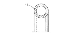
図2および図3では、断面円形とされ、その中心部に芯金20がインサートされたゴムリングあるいは樹脂リングを弾性リング17としている。
上記のように、芯金20がインサートされたゴムリングや樹脂リングを弾性リング17とすると、芯金がインサートされていない弾性リングに比較して保形性に優れ、リング溝16に対する組込み状態おいても円形状態を確保する。
ここで、保形性の低い弾性リング17の場合、リング溝16に対する組込み状態において自重により変形して弛みが生じ、周方向の一部がリング溝16から内径側に大きくはみ出して複列内輪11の嵌合を阻害する可能性があるが、上記のような芯金入りの弾性リング17は保形性に優れているため、弛みが生じて複列内輪11の嵌合を阻害するという不都合の発生はなく、回転軸2に対して複列内輪11を円滑に嵌合することができる。
図4では、断面が円環状とされて中空部21を有し、その円環状断面の周方向の一部に径方向の切り離し部22が形成され、その切り離し部22から中空部21内に輪状のコイルばね23が挿入されて拡径方向への弾性力が付与されたゴムリングや樹脂リングを弾性リング17としている。
上記弾性リング17においてもコイルばね23の組込みによって保形性に優れたものとなり、図2および図3に示す弾性リング17と同様に、複列内輪11の嵌合を阻害するという不都合の発生はなく、回転軸2に対して複列内輪11を円滑に嵌合することができる。
図5では、断面円環状とされた金属リングを弾性リング17としている。この弾性リング17においても、剛性が高いため、保形性に優れ、複列内輪11の嵌合を阻害するという不都合の発生はなく、回転軸2に対して複列内輪11を円滑に嵌合することができる。
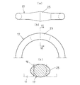
図6(a)乃至(c)では、ゴムあるいは樹脂からなるリング本体24に複列内輪11に形成されたリング溝16の溝幅より幅寸法の大きな幅広部25を周方向の少なくとも一部に形成したリング状物を弾性リング17としている。
上記弾性リング17においては、リング溝16に対する組込み時、幅広部25がリング溝16に圧入されるため、安定した組込み状態を得ることができる。
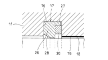
図7では、ゴムあるいは樹脂からなるリング本体26を断面矩形とし、そのリング本体26の一側面における外周部に薄肉円筒部27を設け、上記リング本体26の回転軸2の外径面に弾性接触される内径面と他側面の交差部にテーパ面28を形成したリング状物を弾性リング17としている。
上記の構成からなる弾性リング17においては、複列内輪11のリング溝16に対する組込み後、上記リング溝16内にスナップリング30を縮径状態で組み込み、そのスナップリング30の復元弾性により薄肉円筒部27をリング溝16の周壁内面に押し付けて組込み状態を確保する。
上記弾性リング17においては、リング本体26の回転軸2の外径面に弾性接触される内径面と他側面の交差部にテーパ面28が形成されているため、回転軸2に対する複列内輪11の嵌合時、上記テーパ面28が回転軸2の端面外周部で接触案内されることになり、回転軸2の外径面に複列内輪11をスムーズに嵌合することができる。
図1に示す実施の形態においては、二個の複列内輪11のそれぞれの内径面の両端部に一対のリング溝16を形成し、それぞれのリング溝16内に弾性リング17を組込むようにしたが、図8に示すように、二個の複列内輪11の突合せ端に跨るようにしてリング溝16を形成し、そのリング溝16を二個の複列内輪11の共通のリング溝としてもよい。
上記のように、二個の複列内輪11の突合せ端側部に形成されたリング溝16を、二個の複列内輪11の突合せ端に跨る形成として共通とすることにより、部品点数を削減し、組立ての容易化を図ることができる。
なお、実施の形態においては、複列内輪を有する円すいころ軸受として四列円すいころ軸受を示したが、円すいころ軸受は四列円すいころ軸受に限定されず、一個の複列内輪と二個の外輪によって構成される複列円すいころ軸受であってもよい。
2 回転軸
11 複列内輪
16 リング溝
17 弾性リング
18 嵌め合い隙間
19 潤滑剤層
20 芯金
21 中空部
22 切り離し部
23 コイルばね
25 幅広部
27 薄肉円筒部
28 テーパ面
30 スナップリング
11 複列内輪
16 リング溝
17 弾性リング
18 嵌め合い隙間
19 潤滑剤層
20 芯金
21 中空部
22 切り離し部
23 コイルばね
25 幅広部
27 薄肉円筒部
28 テーパ面
30 スナップリング
Claims (7)
- 少なくとも一つの複列内輪を有し、その複列内輪を回転軸に対してすきま嵌めの嵌め合いとして回転軸を回転自在に支持する円すいころ軸受において、
前記複列内輪の内径面における両端部に一対のリング溝を設け、その一対のリング溝のそれぞれ内部に前記回転軸の外径面に弾性接触する弾性リングを組込んで複列内輪の内径面と回転軸の外径面間に密閉状の嵌め合い隙間を形成し、その密閉状の嵌め合い隙間内に潤滑剤を収容したことを特徴とする円すいころ軸受。 - 前記複列内輪が、側面を突き合わせて軸方向に配列された二個の複列内輪からなり、その二個の複列内輪の突合せ端側部に形成されたリング溝を、二個の複列内輪の突合せ端に跨る形成として共通とした請求項1に記載の円すいころ軸受。
- 前記弾性リングが、断面円形とされ、その中心部に芯金がインサートされたゴムリング又は樹脂リングからなる請求項1又は2に記載の円すいころ軸受。
- 前記弾性リングが、断面円環状とされて中空部を有し、その円環状断面の周方向の一部に径方向の切り離し部が形成され、その切り離し部から中空部内に輪状のコイルばねが挿入されて拡径方向への弾性力が付与されたゴムリング又は樹脂リングからなる請求項1又は2に記載の円すいころ軸受。
- 前記弾性リングが、断面円環状とされた金属リングからなる請求項1又は2に記載の円すいころ軸受。
- 前記弾性リングが、前記リング溝の溝幅よりも幅寸法の大きな複数の幅広部を周方向の少なくとも一部に有してなる請求項1乃至5のいずれか1項に記載の円すいころ軸受。
- 前記弾性リングが、前記リング溝に縮径状態で組み込まれるスナップリングの復元弾性によってリング溝の周壁内面に押し付けられる薄肉円筒部を一側面の外周部に有する断面矩形状とされ、前記回転軸の外径面に弾性接触される内径面と他側面の交差部にテーパ面が形成されたゴムリングまたは樹脂リングからなる請求項1又は2に記載の円すいころ軸受。
Applications Claiming Priority (2)
| Application Number | Priority Date | Filing Date | Title |
|---|---|---|---|
| JP2013-051722 | 2013-03-14 | ||
| JP2013051722A JP2014177985A (ja) | 2013-03-14 | 2013-03-14 | 円すいころ軸受 |
Publications (1)
| Publication Number | Publication Date |
|---|---|
| WO2014141986A1 true WO2014141986A1 (ja) | 2014-09-18 |
Family
ID=51536650
Family Applications (1)
| Application Number | Title | Priority Date | Filing Date |
|---|---|---|---|
| PCT/JP2014/055727 Ceased WO2014141986A1 (ja) | 2013-03-14 | 2014-03-06 | 円すいころ軸受 |
Country Status (2)
| Country | Link |
|---|---|
| JP (1) | JP2014177985A (ja) |
| WO (1) | WO2014141986A1 (ja) |
Cited By (4)
| Publication number | Priority date | Publication date | Assignee | Title |
|---|---|---|---|---|
| WO2019140547A1 (zh) * | 2018-01-16 | 2019-07-25 | 舍弗勒技术股份两合公司 | 轴承固定装置及包括该轴承固定装置的混合动力模块 |
| CN110778602A (zh) * | 2018-12-22 | 2020-02-11 | 杨霞 | 可拆卸的双向轴承装置 |
| US10731743B2 (en) | 2011-11-16 | 2020-08-04 | Roller Bearing Company Of America, Inc. | Cam follower and yoke roller assemblies |
| CN117181816A (zh) * | 2023-09-28 | 2023-12-08 | 瓦房店轴承集团国家轴承工程技术研究中心有限公司 | 轧机用四列圆锥滚子轴承 |
Families Citing this family (1)
| Publication number | Priority date | Publication date | Assignee | Title |
|---|---|---|---|---|
| DE102015218865B4 (de) * | 2015-09-30 | 2024-02-15 | Aktiebolaget Skf | Lageranordnung |
Citations (6)
| Publication number | Priority date | Publication date | Assignee | Title |
|---|---|---|---|---|
| JPH0218918U (ja) * | 1988-07-22 | 1990-02-08 | ||
| JPH0423820U (ja) * | 1990-06-20 | 1992-02-26 | ||
| JPH0632746U (ja) * | 1992-09-30 | 1994-04-28 | エヌティエヌ株式会社 | 転がり軸受 |
| JP2006312955A (ja) * | 2005-05-06 | 2006-11-16 | Nsk Ltd | 転がり軸受 |
| JP2009115133A (ja) * | 2007-11-02 | 2009-05-28 | Ntn Corp | 転がり軸受 |
| JP2009257346A (ja) * | 2008-04-11 | 2009-11-05 | Jtekt Corp | 転がり軸受 |
-
2013
- 2013-03-14 JP JP2013051722A patent/JP2014177985A/ja active Pending
-
2014
- 2014-03-06 WO PCT/JP2014/055727 patent/WO2014141986A1/ja not_active Ceased
Patent Citations (6)
| Publication number | Priority date | Publication date | Assignee | Title |
|---|---|---|---|---|
| JPH0218918U (ja) * | 1988-07-22 | 1990-02-08 | ||
| JPH0423820U (ja) * | 1990-06-20 | 1992-02-26 | ||
| JPH0632746U (ja) * | 1992-09-30 | 1994-04-28 | エヌティエヌ株式会社 | 転がり軸受 |
| JP2006312955A (ja) * | 2005-05-06 | 2006-11-16 | Nsk Ltd | 転がり軸受 |
| JP2009115133A (ja) * | 2007-11-02 | 2009-05-28 | Ntn Corp | 転がり軸受 |
| JP2009257346A (ja) * | 2008-04-11 | 2009-11-05 | Jtekt Corp | 転がり軸受 |
Cited By (5)
| Publication number | Priority date | Publication date | Assignee | Title |
|---|---|---|---|---|
| US10731743B2 (en) | 2011-11-16 | 2020-08-04 | Roller Bearing Company Of America, Inc. | Cam follower and yoke roller assemblies |
| WO2019140547A1 (zh) * | 2018-01-16 | 2019-07-25 | 舍弗勒技术股份两合公司 | 轴承固定装置及包括该轴承固定装置的混合动力模块 |
| EP3742007A4 (de) * | 2018-01-16 | 2021-09-01 | Schaeffler Technologies AG & Co. KG | Lagerbefestigungsvorrichtung und hybridleistungsmodul mit einer lagerbefestigungsvorrichtung |
| CN110778602A (zh) * | 2018-12-22 | 2020-02-11 | 杨霞 | 可拆卸的双向轴承装置 |
| CN117181816A (zh) * | 2023-09-28 | 2023-12-08 | 瓦房店轴承集团国家轴承工程技术研究中心有限公司 | 轧机用四列圆锥滚子轴承 |
Also Published As
| Publication number | Publication date |
|---|---|
| JP2014177985A (ja) | 2014-09-25 |
Similar Documents
| Publication | Publication Date | Title |
|---|---|---|
| JP3200253U (ja) | 密封装置付き転がり軸受 | |
| WO2014141986A1 (ja) | 円すいころ軸受 | |
| US10697493B2 (en) | Cam follower with multiple rows of independently operating bearings | |
| JP2013079706A (ja) | 転がり軸受 | |
| JP2018021569A (ja) | 転がり軸受 | |
| JP2011033171A (ja) | 軸受装置 | |
| JP6485014B2 (ja) | 転がり軸受 | |
| JP2013145024A (ja) | 円筒ころ軸受用保持器 | |
| US20160076585A1 (en) | Double row preloaded ball bearing with spacer balls | |
| JP5651966B2 (ja) | ころ軸受 | |
| JP2018109448A (ja) | 円すいころ軸受 | |
| JP2006322564A (ja) | ベアリング | |
| MX2011002282A (es) | Sello de cojinete para ferrocarril. | |
| JP5022000B2 (ja) | 密封装置および転がり軸受装置 | |
| JP2017053420A (ja) | 転がり軸受 | |
| JP2009052588A (ja) | 転がり軸受 | |
| JP2016023727A (ja) | 転がり軸受の密封装置及び転がり軸受 | |
| JP2010048301A (ja) | 軸受装置 | |
| JP2015161405A (ja) | 密封装置付き転がり軸受 | |
| JP2009168106A (ja) | ころ軸受及びころ軸受の固定構造 | |
| JP4915346B2 (ja) | 固体潤滑ころ軸受 | |
| JP2008175329A (ja) | 転がり軸受用保持器 | |
| WO2016194981A1 (ja) | 円すいころ軸受 | |
| JP2013015201A (ja) | 円すいころ軸受 | |
| JP2015230023A (ja) | 複列円筒ころ軸受 |
Legal Events
| Date | Code | Title | Description |
|---|---|---|---|
| 121 | Ep: the epo has been informed by wipo that ep was designated in this application |
Ref document number: 14762801 Country of ref document: EP Kind code of ref document: A1 |
|
| NENP | Non-entry into the national phase |
Ref country code: DE |
|
| 122 | Ep: pct application non-entry in european phase |
Ref document number: 14762801 Country of ref document: EP Kind code of ref document: A1 |