WO2014132885A1 - ゴルフ用具フィッティングシステム、及びゴルフ用具フィッティングプログラム - Google Patents
ゴルフ用具フィッティングシステム、及びゴルフ用具フィッティングプログラム Download PDFInfo
- Publication number
- WO2014132885A1 WO2014132885A1 PCT/JP2014/054140 JP2014054140W WO2014132885A1 WO 2014132885 A1 WO2014132885 A1 WO 2014132885A1 JP 2014054140 W JP2014054140 W JP 2014054140W WO 2014132885 A1 WO2014132885 A1 WO 2014132885A1
- Authority
- WO
- WIPO (PCT)
- Prior art keywords
- swing
- golf
- specifications
- result
- simulation
- Prior art date
- Legal status (The legal status is an assumption and is not a legal conclusion. Google has not performed a legal analysis and makes no representation as to the accuracy of the status listed.)
- Ceased
Links
Images








Classifications
-
- A—HUMAN NECESSITIES
- A63—SPORTS; GAMES; AMUSEMENTS
- A63B—APPARATUS FOR PHYSICAL TRAINING, GYMNASTICS, SWIMMING, CLIMBING, OR FENCING; BALL GAMES; TRAINING EQUIPMENT
- A63B60/00—Details or accessories of golf clubs, bats, rackets or the like
-
- A—HUMAN NECESSITIES
- A63—SPORTS; GAMES; AMUSEMENTS
- A63B—APPARATUS FOR PHYSICAL TRAINING, GYMNASTICS, SWIMMING, CLIMBING, OR FENCING; BALL GAMES; TRAINING EQUIPMENT
- A63B60/00—Details or accessories of golf clubs, bats, rackets or the like
- A63B60/46—Measurement devices associated with golf clubs, bats, rackets or the like for measuring physical parameters relating to sporting activity, e.g. baseball bats with impact indicators or bracelets for measuring the golf swing
-
- A—HUMAN NECESSITIES
- A61—MEDICAL OR VETERINARY SCIENCE; HYGIENE
- A61B—DIAGNOSIS; SURGERY; IDENTIFICATION
- A61B5/00—Measuring for diagnostic purposes; Identification of persons
- A61B5/103—Measuring devices for testing the shape, pattern, colour, size or movement of the body or parts thereof, for diagnostic purposes
- A61B5/11—Measuring movement of the entire body or parts thereof, e.g. head or hand tremor or mobility of a limb
-
- A—HUMAN NECESSITIES
- A61—MEDICAL OR VETERINARY SCIENCE; HYGIENE
- A61B—DIAGNOSIS; SURGERY; IDENTIFICATION
- A61B5/00—Measuring for diagnostic purposes; Identification of persons
- A61B5/68—Arrangements of detecting, measuring or recording means, e.g. sensors, in relation to patient
- A61B5/6887—Arrangements of detecting, measuring or recording means, e.g. sensors, in relation to patient mounted on external non-worn devices, e.g. non-medical devices
- A61B5/6895—Sport equipment
-
- A—HUMAN NECESSITIES
- A63—SPORTS; GAMES; AMUSEMENTS
- A63B—APPARATUS FOR PHYSICAL TRAINING, GYMNASTICS, SWIMMING, CLIMBING, OR FENCING; BALL GAMES; TRAINING EQUIPMENT
- A63B69/00—Training appliances or apparatus for special sports
- A63B69/36—Training appliances or apparatus for special sports for golf
- A63B69/3605—Golf club selection aids informing player of his average or expected shot distance for each club
-
- G—PHYSICS
- G06—COMPUTING OR CALCULATING; COUNTING
- G06V—IMAGE OR VIDEO RECOGNITION OR UNDERSTANDING
- G06V40/00—Recognition of biometric, human-related or animal-related patterns in image or video data
- G06V40/20—Movements or behaviour, e.g. gesture recognition
- G06V40/23—Recognition of whole body movements, e.g. for sport training
-
- A—HUMAN NECESSITIES
- A63—SPORTS; GAMES; AMUSEMENTS
- A63B—APPARATUS FOR PHYSICAL TRAINING, GYMNASTICS, SWIMMING, CLIMBING, OR FENCING; BALL GAMES; TRAINING EQUIPMENT
- A63B53/00—Golf clubs
-
- A—HUMAN NECESSITIES
- A63—SPORTS; GAMES; AMUSEMENTS
- A63B—APPARATUS FOR PHYSICAL TRAINING, GYMNASTICS, SWIMMING, CLIMBING, OR FENCING; BALL GAMES; TRAINING EQUIPMENT
- A63B69/00—Training appliances or apparatus for special sports
- A63B69/36—Training appliances or apparatus for special sports for golf
-
- G—PHYSICS
- G06—COMPUTING OR CALCULATING; COUNTING
- G06F—ELECTRIC DIGITAL DATA PROCESSING
- G06F2218/00—Aspects of pattern recognition specially adapted for signal processing
Definitions
- the present invention relates to a golf equipment fitting system and a golf equipment fitting program.
- the fitting technology solves this.
- a technique described in Patent Document 1 can be given.
- the head behavior at the moment of impact is photographed with a high-speed camera, and the head posture is quantified by replacing it with three-dimensional coordinates by the DLT method.
- the head posture at the time of impact can be specified for each club, and an appropriate club can be selected.
- Patent Document 2 There is a technique described in Patent Document 2 as a technique that can solve this problem.
- the swing is first measured and the head behavior is simulated based on the swing data.
- a player can obtain results equivalent to hundreds of test hits by performing only one swing measurement.
- the golfer hits the ball by changing the swing itself. For this reason, even if a club or shaft having extremely different performance is simulated with respect to one swing data, the simulation result does not match the actual solution.
- Patent Document 3 As a technique that can solve this problem, the technique of Patent Document 3 can be cited. This is a more realistic phenomenon by calculating the swing that changes for each shaft performance (flex, tone, and torque) using the response surface methodology and simulating the swing after the change. Simulates close to.
- the technique described in Patent Document 3 has a problem that it is difficult to simulate by changing, for example, the “weight” and “length” of the members constituting the golf club.
- the reason for this is that when the weight and length are changed, even the same player, from the address (the golf club is attached to the ground) to the top (the golf club is raised), the impact from the top (the head is the ball) This is because a swing time such as the time of hitting is greatly different and sufficient calculation accuracy cannot be obtained. Therefore, in the technique described in Patent Document 3, the specs of the golf club that can be changed are limited to specs excluding those that greatly affect the swing time such as weight and length.
- the present invention has been made in view of such circumstances, and a golf tool capable of calculating an accurate calculation result and outputting a simulation result in a short time even when a specification affecting the swing time is changed.
- a fitting system and a golf equipment fitting program are provided.
- one aspect of the present invention is obtained by a swing data acquisition unit (21) that acquires swing data from sensors attached to a plurality of golf clubs having different specifications, and the swing data acquisition unit. Based on the swing data, a swing response surface calculation unit (221) that calculates a swing response surface by a response surface method, and a time response surface by a response surface method based on the swing data acquired by the swing data acquisition unit A time response curved surface calculation unit (222) that performs a calculation of swing data of a golf club that is not measured from the swing response curved surface and the time response curved surface, and a simulation that executes a golf swing simulation based on the calculated swing data An execution unit (23) and the simulation Golf equipment fitting system with result output unit for outputting a simulation result of the emission execution unit (24), a (2).
- the specifications of the plurality of golf clubs used for the simulation include at least weight.
- one aspect of the present invention is characterized in that in the golf equipment fitting system, the specifications of the plurality of golf clubs used for the simulation include at least a club length.
- the specifications of the plurality of golf clubs used in the simulation are different from each other in at least two specifications, and the at least two different specifications are different from each other in influence degree. Is within a predetermined range.
- the specifications of the plurality of golf clubs used in the simulation include three different specifications and 27 specifications each having three levels, Nine specifications selected based on the L9 orthogonal table in the experimental design method are characterized.
- one aspect of the present invention is characterized in that, in the golf equipment fitting system, the three different specifications are weight, tone, and flex.
- one aspect of the present invention is characterized in that, in the golf equipment fitting system, the three different specifications are selected from club hardness, club length, total club weight, and club balance.
- one aspect of the present invention is characterized in that, in the golf equipment fitting system, the three different specifications are selected from a center of gravity height, a center of gravity depth, a center of gravity distance, and a center of gravity angle.
- the three different specifications are a loft angle, a lie angle, and a face angle of a head.
- the division level number of the first specification is i
- the level is l
- the division level number of the second specification is j.
- the result output unit outputs (l ⁇ 1) i + (m ⁇ 1) j + ( n-1) assigns a result number defined by k, replaces the result number by subtracting (j-1) ⁇ k ⁇ (l-1) from the result number as a plot number, and Data obtained by plotting the axis and the simulation result as the vertical axis is output as the fitting result.
- the result output unit in the output of the fitting result, includes a line segment between the plotted data that satisfy the following conditions (i) to (iii): It is characterized by being connected and output.
- the third specification is different from the first and second specifications and the first and second specifications are the same.
- the result output unit converts the fitting result into a natural language according to the relationship between each absolute value and inclination, and outputs the natural language.
- the result output unit converts a specification indicating a maximum value of the simulation result into a product name and outputs the product name.
- one aspect of the present invention is characterized in that, in the golf equipment fitting system, the output unit selects and displays a golf club based on a simulation result by the simulation execution unit.
- one aspect of the present invention is acquired by a swing data acquisition procedure for acquiring swing data from sensors attached to a plurality of golf clubs having different specifications, and the swing data acquisition procedure.
- a swing response surface calculation procedure for calculating a swing response surface by the response surface method based on the swing data, and a time response surface for calculating a time response surface by the response surface method based on the swing data acquired by the swing data acquisition procedure
- an accurate calculation result can be calculated and a simulation result can be output in a short time even when the specification affecting the swing time is changed.
- FIG. 1 It is a block diagram which shows the structure of the 1st Embodiment of this invention. It is explanatory drawing which shows an example of the specification of a golf shaft. It is explanatory drawing which shows an example of the specification of a golf shaft and a golf club head. It is a figure which shows the specification of nine golf clubs used for the trial hit for obtaining swing data. It is a flowchart which shows operation
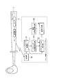
- FIG. 1 is a block diagram showing the configuration of the embodiment.
- reference numeral 1 denotes a golf club on which a golf shaft whose specifications are known in advance is mounted, and a sensor 11 inside the shaft of the grip portion and a transmission unit 12 that transmits the output of the sensor 11 to the outside by wireless communication. It has.
- the sensor 11 may be attached to the outside of the shaft.
- the sensor 11 is a 6-axis sensor that detects and outputs 3-axis acceleration and 3-axis angular velocity.
- the senor 11 may be a nine-axis sensor that measures the three-axis orientation using geomagnetism in addition to the three-axis acceleration and the three-axis angular velocity.
- two sensors, a 6-axis sensor and a 3-axis geomagnetic sensor, may be used.
- Numeral 2 is a golf equipment fitting system constituted by a computer device.
- Reference numeral 20 denotes a receiving unit that receives sensor output data (swing data) transmitted by the transmitting unit 12.
- Reference numeral 21 denotes a swing data acquisition unit that acquires swing data via the reception unit 20.
- Reference numeral 221 denotes a swing response curved surface calculation unit that obtains a swing response curved surface when the golf club 1 is hit from the acquired swing data.
- Reference numeral 222 denotes a time response surface calculation unit that obtains a response surface of a swing time when the golf club 1 is hit on trial from the acquired swing data.
- Reference numeral 23 denotes a simulation execution unit that performs a simulation by FEM (Finite Element Method) using a swing response curved surface and a time response curved surface.
- Reference numeral 24 denotes a result output unit that outputs the result of the simulation executed by the simulation execution unit 23.
- the golf club 1 used for a trial hit for obtaining swing measurement data will be described.
- the golfer takes into consideration the weight, bending rigidity, torsional rigidity, etc. of the shaft used when performing the swing, and performs the swing according to the club characteristics. For this reason, it may be difficult to obtain a proper analysis result even if the swing measurement data is obtained by using one golf club having a predetermined characteristic and the swing is analyzed. That is, if the club specifications are different, the swing is different. Therefore, as an example, based on the experimental design method, three different specifications were selected from the specifications of a number of golf clubs, and a total of 27 clubs were prepared with three levels for each specification. Among them, nine golf clubs were selected based on the L9 orthogonal table.
- 3 3 27 clubs must be experimented when attempting to obtain data of 3 factors and 3 levels without using the experimental design method, and it is difficult to actually experiment.
- specifications of the weight of the shaft, the bending rigidity of the shaft (corresponding to the flex of the shaft spec, hereinafter referred to as flex), and the bending rigidity distribution of the shaft (corresponding to the tone of the shaft spec, hereinafter referred to as tone) are used.
- the specs of the clubs used are exemplified by three specs differing at three levels, but the present invention is not limited to this as long as it is a golf club including a plurality of different specs.
- the present embodiment can be suitably used particularly for golf clubs having different weight and length specifications.
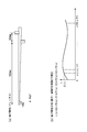
- the three specifications of the shaft illustrated this time are the functions of the weight of the shaft alone, the flex defined by the deflection (FIG. 2A), and the point where the bending of the shaft becomes the largest.
- the tone is defined by the coefficient C of P (FIG. 2B).
- FIG. 2A as an example, a position of 920 mm from the small-diameter side end of the shaft is supported from the lower side, and a further 150-mm large-diameter side position (1070 mm from the small-diameter side end) from there. A state where a load of 3.0 kgf is applied at a position 10 mm from the small diameter side is shown. The amount of displacement at the end on the narrow diameter side at this time represents flex (bending rigidity).
- FIG. 2B shows an example of tone (bending stiffness distribution L (x)).
- EI (i) indicates bending rigidity
- x indicates a position on the shaft with respect to the tip of the shaft.
- the tone is classified into the main tone that is closer to the grip, the tip tone that is closer to the head, and the middle tone that is in the middle where the shaft has the largest bending.
- the tone is assigned to one of the original tone, the first tone, and the middle tone depending on the value defined by the coefficient C of the function P.
- Swing data is acquired using the nine golf clubs 1 described above.
- shaft torsional rigidity corresponding to shaft spec torque, hereinafter referred to as torque
- shaft torsional rigidity distribution corresponding to shaft spec torque, hereinafter referred to as torque
- shaft torsional rigidity distribution shaft weight distribution
- golf club length corresponding to shaft spec torque
- head weight corresponding to club spec torque
- club balance corresponding to club spec torque
- head center of gravity depth head It is possible to apply the center of gravity height, the head center-of-gravity distance, the grip weight, the loft angle, the lie angle, and the face angle.
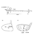
- the torque is defined by the torsion angle of the shaft.
- FIG. 3A shows, as an example, a state in which a position of 1035 mm is fixed from the small-diameter end of the shaft and a torsional load is applied to a position of 45 mm from the tip of the shaft.
- A can be rotated with the bending direction fixed, and B is completely fixed.
- a torsional load of 1.152 kgf is applied at a position 120 mm away from the shaft axis.
- the twist angle of the shaft small diameter side end at this time is defined as torque.
- the head center-of-gravity depth is defined by the depth (distance) from the face surface to the center of gravity of the head (FIG. 3B).
- the head center of gravity height is defined by the length from the leading edge to the center of gravity on the face surface, and the center of gravity distance is defined by the length when a perpendicular is extended from the shaft axis toward the center of gravity on the face surface.
- the torsional rigidity distribution of the shaft and the weight distribution of the shaft can be expressed exactly the same as the relationship between the bending rigidity distribution and the tone.
- Club balance (also called swing weight) indicates how well the golf club head is working (how easy it is to feel the weight of the head during a swing or waggle).
- the club balance is measured using a club balance meter “Golf Club Scale” manufactured by Kenneth Smith.
- Club hardness is expressed as the frequency with the grip and head attached. This frequency is measured using “Golf Club Timing Harmonizer” manufactured by Fujikura Rubber Industries. For example, when the club head is vibrated with 180 mm fixed from the grip end, the vibration frequency per minute at a position of 760 mm from the grip end is defined as the club hardness.
- FIG. 4 shows the specifications of nine golf clubs used for trial hits for obtaining swing data based on the experimental design method L9 type orthogonal table.
- the shaft weight indicates a normalized value, and a smaller value means that the weight is heavier. Flex indicates a normalized value, and a smaller value means higher rigidity.
- Both the shaft weight and the flex have adopted a range that functions as a golf shaft when it has a specified length and diameter.
- the shaft weight when 0, the shaft weight is 80 g, when 0.5, the shaft weight is 70 g, and when 1, the shaft weight is 60 g.
- the flex (bending stiffness) value when 0, the flex (bending stiffness) value is 130 mm, when 0.5, the flex (bending stiffness) value is 180 mm, and when flex is 1, the flex (bending stiffness) value.
- the tone As for the tone, the tone is 0 when the tone is 0, the tone is 0.5, the tone is medium, and the tone is 1 when the tone is original.
- the number of clubs used is not limited to nine as long as it is a quantity that can be realistically tested.
- the head attached to the golf club shown in FIG. 4 is using the same thing, and the shaft length and the weight of a golf club are also the same. This is a measure for eliminating a change caused by other factors by using a golf club having the same specifications other than the specifications to be fitted.
- the sensor 11, the transmission unit 12, and these are operated so that the total weight of the golf club 1 is not increased by inserting the sensor 11, the transmission unit 12, etc. into the shaft. Therefore, the weight of the entire equipment necessary for this is suppressed to 20 g. Thereby, since an increase in the total weight can be suppressed by using a commercially available lightweight grip, an adverse effect on the swing due to an increase in the weight of the club is suppressed.
- a person who performs a test hit (a user to be fitted) performs a test hit using the golf club 1 having a club number “1” among the nine golf clubs 1.
- the sensor 11 outputs a detection result (swing data) during the trial hitting operation to the transmission unit 12.
- the transmission unit 12 transmits the swing data to the outside using wireless communication.
- This swing data is received by the receiving unit 20 and output to the swing data acquiring unit 21.
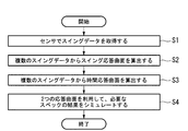
- the swing data acquisition unit 21 holds this swing data inside (step S1).
- the swing data acquisition unit 21 was tried once by each of at least nine golf clubs 1. In this case, time-series swing data is held.
- the swing data acquisition unit 21 converts the acquired swing data into movement speed data of the grip portion of the golf club 1 and shaft rotation data of the shaft. This conversion is performed by geometrically converting the mounting position of the sensor 11 inserted into the golf club 1 and the predetermined two-point positional relationship of the grip portion of the golf club 1.
- the swing data acquisition unit 21 refers to the swing data, and swing data from the top of the swing (a state where the golf club is raised) to an impact (a state where the head hits the ball) from the swing data. Were converted into movement speed data and shaft rotation data. However, the swing data from the address (the state in which the golf club is attached to the ground) to the impact may be analyzed.
- the swing response surface calculation unit 221 reads the swing data of the nine clubs held in the swing data acquisition unit 21, and calculates a swing response surface that is a linear function of the skill and skill of the test batter.
- the swing response curved surface refers to the golf club grip speed data and shaft rotation data obtained by trial hitting with nine types of golf clubs shown in FIG. 4, and three specifications of the golf club (here, the shaft weight, (Flex, tone).
- the swing data is from f 1 to f 9 , but the value varies depending on the number of golf clubs that are hit.
- f j (t i) is a weight measurement by j-th golf club, in particular 3-direction acceleration ⁇ a x, a y, a z ⁇ , 3 directions the angular velocity ⁇ x, ⁇ y, ⁇ z ⁇ The amount of each is shown.
- Equation 1 Equation 1 is solved for each t i .
- x, y, and z are design variables, respectively, where x is a first specification (shaft weight), y is a second specification (flex), and z is a third specification (tone).
- the numbers 1 to n in x 1 to x n , y 1 to y n , and z 1 to z n correspond to the number of each club.
- the x bar, y bar, and z bar are given arbitrary values convenient for each analysis (for example, intermediate values of design variables).
- Equation 2 coefficients a 1 to a 4 of the response surface can be obtained as Equation 2.
- numerical calculation software “MATLAB” manufactured by MathWorks was used.
- the coefficients a 1 to a 4 obtained by Expression 2 are values corresponding to the skill of the test hitter and the trap of the swing. That is, by this process, even if x, y, and z are changed to specifications that are not actually measured, the swing data represented by the function f is obtained as shown in Equation 3. In other words, the following is obtained as an approximate value of the three-way acceleration and the three-way angular velocity with respect to an arbitrary ⁇ x, y, z ⁇ by Equation 3. From Equation 3, the swing data from any m-th shaft that has not been measured is expressed as shown in Equation 4.
- F m (t) expressed by Equation 4 is a swing response surface.
- the time response curved surface calculation unit 222 reads the swing data of the nine clubs held in the swing data acquisition unit 21, and calculates a time response curved surface that formulates the swing time of the test hitter (step S3).
- the time response curved surface is a relational expression between the swing time obtained when the golf clubs of nine types shown in FIG. 4 are tested and the three specifications of the golf club (here, shaft weight, flex, tone).
- the time response surface can be calculated by Equations 6 to 8.
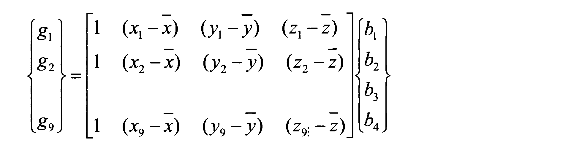
- Equation 6 g 1 to g 9 are swing times of the golf clubs.
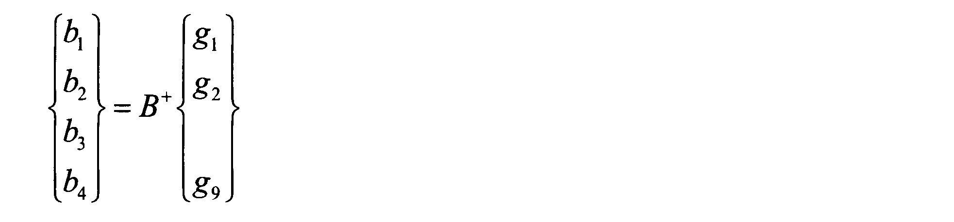
- the coefficients b 1 to b 4 obtained by Expression 7 are values corresponding to the swing time of the test hitter. By this process, the difference in swing time due to the difference in weight can be calculated.
- Equation 8 each t is converted to g m.
- G m represented by Expression 8 is a time response curved surface.
- f m ′ (t) derived from Equation 9 is swing data newly calculated based on the swing response surface and the time response surface.
- the simulation execution unit 23 includes the movement speed data and shaft rotation data of the grip portion that have been measured and stored in the swing data acquisition unit 21, the swing response curved surface calculated by the swing response curved surface calculation unit 221, and the time response curved surface calculation unit 222.
- the swing data of the golf club that has not been measured is calculated from the time response curved surface calculated by.
- the simulation execution unit 23 simulates the motion of the golf club head by the dynamic finite element method based on the calculated swing data (step S4).
- Simulation results showing the motion of the golf club obtained by this analysis are: club speed at impact, face angle (horizontal angle with respect to the flying line of the club face), impact loft (loft angle with respect to the ground at impact) It is.
- Club speed corresponds to the distance of the ball.
- the face angle corresponds to the directionality of the sphere.
- the impact loft corresponds to the ballistic height.
- various values such as a club pass, an attack angle, a ball speed, and a flight distance can be taken.
- the simulation execution unit 23 uses a golf club of all possible specs and inputs a swing response surface obtained by linearizing the skill and skill of the test batter and a time response surface obtained by formulating the swing time of the test batter. Analyzing the motion of a golf club head as For this reason, it is possible to simulate the golf club motion in consideration of the skill, the heel and the swing time of the test hitter (the nature of the swing and the change in the swing time when the specifications are different).
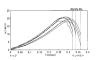
- Equation 2 it is necessary to keep t constant in order to solve Equation 2 using the generalized inverse matrix as described above.
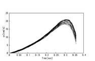
- the time response surface calculation unit 222 obtains a time response surface. By converting t again according to the obtained time response curved surface, swing data reflecting the swing time can be obtained.
- FIG. 8 shows data calculated using only a swing response surface
- FIG. 9 shows data calculated using a swing response surface and a time response surface.
- the shaft weight level (number of division levels i of the first specification), which is the spec of the golf shaft to be calculated, is 3, the level of flex (number of division levels j of the second specification) is 5, and the level of tone A description will be made assuming that (the number of division levels k of the third specification) is 5.
- the number of division levels is obtained by dividing the nine specs that were actually tried out into arbitrary numbers. For example, taking the flex as an example, among the 9 actually tried hits, there are X, R, and L in the flex.
- the results can also be calculated for the other flex, ie, S, A (the flex is represented by X, S, R, A, L from the harder one).
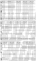
- the result data is output as a screen display with the club speed as the vertical axis and the simulation number as the horizontal axis, for example, the display is as shown in FIG. In this case, it is difficult to grasp which value indicates a shaft having what specification value.
- FIG. 11 shows the relationship between the simulation number and the specifications of the golf club.
- the user can read the specification value of the golf shaft by performing the following processing.
- Result number The number of division levels of the first specification is i, the level is l, the number of division levels of the second specification is j, the level is m, the number of division levels of the third specification is k, and the level is n And (l ⁇ 1) i + (m ⁇ 1) j + (n ⁇ 1) k for the simulation result. In other words, it is as follows.
- the level of the first specification and the second specification is set to the minimum value, and the level of the third specification is changed from the minimum value to the maximum value.
- the level of the first specification is set to the minimum value, the level of the second specification is increased by one level, and the level of the third specification is changed from the minimum value to the maximum value.
- [3] Repeat [2] until the level of the second specification reaches the maximum value.
- [4] Increase the level of the first specification by one level, and execute [2] and [3].
- [5] Repeat [4] until the level of the first specification reaches the maximum value.
- the shaft weight is fixed at the first level, the flex is fixed at the first level, and the tone is changed from the previous tone to the original tone at five levels.
- the shaft weight is fixed at the first level, the flex is fixed at the second level, and the tone is changed from the previous tone to the original tone at five levels.
- the shaft weight is fixed at the first level, the flex is fixed at the third level, and the tone is changed from the previous tone to the original tone at five levels.
- D The shaft weight is fixed at the first level, the flex is fixed at the fourth level, and the tone is changed from the previous tone to the original tone at five levels.
- the shaft weight is fixed at the first level, the flex is fixed at the fifth level, and the tone is changed from the previous tone to the original tone at five levels.
- the shaft weight is fixed at the second level, the flex is fixed at the first level, and the tone is changed from the previous tone to the original tone at five levels.
- the shaft weight is fixed at the second level, the flex is fixed at the second level, and the tone is changed from the previous tone to the original tone at five levels.
- the shaft weight is fixed at the second level, the flex is fixed at the third level, and the tone is changed from the previous tone to the original tone at five levels.
- the shaft weight is fixed at the second level, the flex is fixed at the fourth level, and the tone is changed from the previous tone to the original tone at five levels.
- the shaft weight is fixed at the second level, the flex is fixed at the fifth level, and the tone is changed from the previous tone to the original tone at five levels.
- the shaft weight is fixed at the third level, the flex is fixed at the first level, and the tone is changed from the previous tone to the original tone at five levels.
- the shaft weight is fixed at the third level, the flex is fixed at the second level, and the tone is changed from the previous tone to the original tone at five levels.
- the shaft weight is fixed at the third level, the flex is fixed at the third level, and the tone is changed from the previous tone to the original tone at five levels.
- N The shaft weight is fixed at the third level, the flex is fixed at the fourth level, and the tone is changed from the previous tone to the original tone at five levels.
- O The shaft weight is fixed at the third level, the flex is fixed at the fifth level, and the tone is changed from the previous tone to the original tone at five levels.
- a shaft weight of 0 indicates that the shaft is heavy (for example, 80 g)
- a shaft weight of 0.5 indicates that the weight of the shaft is medium (for example, 70 g)
- a shaft weight of 1 is , Indicating that the shaft is light (eg, 60 g).
- flex 0 indicates the hardest (eg, flex X) and leads to flex 0.25 (eg, flex S), 0.5 (eg, flex R), 0.75 (eg, flex A). It gradually softens as the value increases.
- Flex 1 indicates the softest (for example, flex L).
- tone 0 indicates the first tone
- tone 0.25 indicates the first tone
- tone 0.5 indicates the middle tone
- tone 0.75 indicates the middle tone
- tone 1 indicates Indicates the original tone.
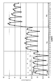
- the result shown in FIG. 13 is obtained.
- the simulation execution unit 23 determines the execution order and performs simulation, and the result output unit 24 outputs the result based on the execution order, so that the tendency of the club speed as shown in FIG. 13 can be grasped. .
- the output format shown in FIG. 13 is still insufficient.
- the result output unit 24 plots again using the value obtained by subtracting (j ⁇ 1) ⁇ k ⁇ (l ⁇ 1) from the result number as the plot number.
- FIG. 14 shows a fitting result obtained by plotting and outputting data by this method.
- the result output unit 24 converts the result number as shown in the following (a) to (e), assigns a new plot number, and plots and outputs the plot number and the simulation result again. . Thereby, the tendency of the relationship between the specification value of the golf equipment and the simulation result can be grasped.
- the vertical axis represents the club speed, and the larger the value, the faster the speed (the flying distance comes out), and the smaller the value, the slower the speed (the flying distance does not come out).
- the horizontal axis is the newly set plot number.
- a circle indicates a golf club associated with a spec. Each value is associated with the values of “flex”, “tone” and “shaft weight” which are specs of the golf shaft.
- the result output unit 24 may display the tendency of specifications in a natural language. That is, the result output unit 24 converts the fitting result into a natural language and displays it according to the relationship between each absolute value and the slope. For example, if the purpose of fitting is to increase the club speed, the result output unit 24 indicates that “the harder the flex, the higher the club speed”, “the lighter the shaft, the higher the club speed”, “the tone is the original tone. “Increased club speed” and “Influence of shaft weight is greatest” are displayed.
- the result output unit 24 indicates that “the harder the flex, the higher the ball”, “the lighter the shaft, the higher the ball”, “ A display such as “the ball rises as much” or “the influence of flex is the greatest” is displayed. Thereby, since the user can grasp the tendency of specifications in a natural language, the golf equipment can be easily selected.
- the result output unit 24 outputs all possible specs instead of outputting only one point of the specifications of the golf shaft when the club speed is maximum. This makes it possible to grasp the specs that can achieve a reasonable flight distance, a moderate trajectory height, and a moderate trajectory bend, so that the specs of the golf shaft can be selected according to user preferences. become. This is particularly effective when the face angle is calculated, and it is preferable for the user that an appropriate trajectory curve can be selected. This is because if you want to bend the trajectory and choose the shaft that bends the maximum, the problem of excessive trajectory of the trajectory will appear.
- the result output part 24 may change and output the line color density so that the best value is noticeable.
- the result output unit 24 may output a means for transmitting to the user that changes to natural language as data obtained by further simplifying FIG.
- the first spec is described as the shaft weight (3 levels), the second spec as flex (5 levels), and the third spec as the tone (5 levels), but other specifications are used. May be.
- the first spec may be torque (5 level), the second spec may be flex (5 level), and the third spec may be tone (5 level).
- the first specification may be flex (5 levels), the second specification may be torque (5 levels), and the third specification may be weight (3 levels).
- a golfer does not require only one performance for a golf club, but a composite performance. For example, maximizing club speed and preventing slicing, and simultaneously increasing the trajectory.
- a complex condition one of the nine trajectories shown in FIG. 15 is selected based on the user's request. The ball trajectory is determined by the height of the trajectory and the direction of the trajectory.
- the ballistic height is divided into “High (high trajectory)”, “Mid (medium trajectory)” and “Low (low trajectory)”, and the trajectory direction is “Fade”, “Stright”, If it is divided into three “Draw”, it can be divided into nine trajectories as shown in FIG.
- the fade is a trajectory that turns to the right when it is right-handed
- the draw is a trajectory that turns to the left when it is right-handed.
- a condition that satisfies the selected trajectory while the club speed is maximized is output.
- a specification that maximizes the objective function F is required.
- f 1 is first result data (eg, club speed)
- f 2 is second result data (eg, face angle)
- f 3 is third result data (eg, face angle). , Impact loft)
- ⁇ , ⁇ , and ⁇ are weighting factors. ⁇ , ⁇ , and ⁇ are appropriately selected according to each golfer's request. In general, ⁇ is preferably 1 to 3 times the value of ( ⁇ + ⁇ ). This is because club speed is most important for golfers.
- FIG. 16 is a diagram showing an output example of a fitting result when the trajectory is low trajectory / draw (Low / Draw) and the club speed is maximized as a complex condition.
- the vertical axis indicates whether it is suitable for hitting the LowDraw trajectory while increasing the club speed. From this figure, it can be seen that the optimum spec for this player is that the shaft weight is 60 g, the flex is S, and the tone is medium.
- the result output unit 24 may convert the specification indicating the maximum value of the simulation result (club speed, impact loft, face angle, etc.) into the product name of the golf equipment and display it.
- the user can easily select a golf equipment that realizes the desired trajectory. become. That is, the golf equipment can be fitted by the above-described golf equipment fitting system. In addition, measurement, analysis, and result display can be performed in a short time, and the optimum specifications of the golf shaft can be visually determined.
- the shaft weight, flex, and tone are selected, but not limited thereto. Further, the number is not limited to three specifications, and may be more or less. As described above, it is preferable that the specifications (for example, weight and club length) with which the swing time is easily changed are different. Others include shaft bending rigidity, shaft torsional rigidity, shaft weight, shaft bending rigidity distribution, shaft torsional rigidity distribution, shaft weight distribution, golf club length, head weight, club balance, head center of gravity depth, head center of gravity height Specs such as head center-of-gravity distance, grip weight, loft angle, lie angle, and face angle can be considered.
- time response curved surface it is possible to use a data obtained by extending each swing data to the longest so that all swing times are equal. In this case, a certain degree of accuracy and a reduction in calculation time can be achieved.
- the degree of influence indicates how much the final head behavior is affected when the specification is changed.
- the degree of influence is shown in FIG. The reason for this is as follows.
- FIG. 18 is a diagram showing simulation results by selecting a head weight (influence degree: 5), a shaft torsional rigidity distribution (influence degree: 1), and a head center of gravity height (influence degree: 1) as three different specifications.
- a head weight influence degree: 5
- a shaft torsional rigidity distribution influence degree: 1
- a head center of gravity height influence degree: 1
- the different specs have a degree of influence within a predetermined range (in the present embodiment, within 2). More preferably, the influence levels of the three different specifications are the same.
- the head speed varies depending on the difference in the head weight that has a large influence, but no difference is seen between the other two specifications.
- shaft weight When selecting and combining three specifications, it is recommended to use shaft weight, bending rigidity (flex), and bending rigidity distribution (tone). In this case, it can be suitably used as a shaft fitting and design.
- bending stiffness (flex), club length, and head weight may be combined. In this case, it can be suitably used as a club fitting and design.
- the center of gravity height, the center of gravity depth, the center of gravity distance, and the center of gravity angle of the head may be combined. In this case, it can be suitably used as a head fitting and design.
- the loft angle, lie angle, and face angle of the head may be combined. In this case, it can be suitably used as a head fitting and design. Further, the club hardness, the club length, the total club weight, and the club balance may be combined.
- a program for realizing each function of the golf equipment fitting system is recorded on a computer-readable recording medium, and the program recorded on the recording medium is read into the computer system and executed, thereby executing the above-described units. Processing may be performed.
- “loading and executing a program recorded on a recording medium into a computer system” includes installing the program in the computer system.
- the “computer system” here includes an OS and hardware such as peripheral devices. Further, the “computer system” may include a plurality of computer devices connected via a network including a communication line such as the Internet, WAN, LAN, and dedicated line.
- the “computer-readable recording medium” refers to a storage device such as a flexible medium, a magneto-optical disk, a portable medium such as a ROM or a CD-ROM, and a hard disk incorporated in a computer system.
- the recording medium storing the program may be a non-transitory recording medium such as a CD-ROM.
- the recording medium also includes a recording medium provided inside or outside that is accessible from the distribution server in order to distribute the program.
- the code of the program stored in the recording medium of the distribution server may be different from the code of the program that can be executed by the terminal device. That is, the format stored in the distribution server is not limited as long as it can be downloaded from the distribution server and installed in a form that can be executed by the terminal device.
- the program may be divided into a plurality of parts, downloaded at different timings, and combined in the terminal device, or the distribution server that distributes each of the divided programs may be different.
- the “computer-readable recording medium” holds a program for a certain period of time, such as a volatile memory (RAM) inside a computer system that becomes a server or a client when the program is transmitted via a network.
- the program may be for realizing a part of the functions described above.
- achieve the function mentioned above in combination with the program already recorded on the computer system what is called a difference file (difference program) may be sufficient.
- part or all of the above-described functions may be realized as an integrated circuit such as an LSI (Large Scale Integration).
- LSI Large Scale Integration
- Each function described above may be individually made into a processor, or a part or all of them may be integrated into a processor.
- the method of circuit integration is not limited to LSI, and may be realized by a dedicated circuit or a general-purpose processor. Further, in the case where an integrated circuit technology that replaces LSI appears due to progress in semiconductor technology, an integrated circuit based on the technology may be used.
- the golf equipment fitting system and the golf equipment fitting program according to the present invention can be applied to the fitting of golf equipment according to a golfer's demand, skill, and skill.
Landscapes
- Health & Medical Sciences (AREA)
- Life Sciences & Earth Sciences (AREA)
- General Health & Medical Sciences (AREA)
- Engineering & Computer Science (AREA)
- Physical Education & Sports Medicine (AREA)
- Physics & Mathematics (AREA)
- Animal Behavior & Ethology (AREA)
- Surgery (AREA)
- Biophysics (AREA)
- Molecular Biology (AREA)
- Medical Informatics (AREA)
- Heart & Thoracic Surgery (AREA)
- Public Health (AREA)
- Biomedical Technology (AREA)
- Pathology (AREA)
- Veterinary Medicine (AREA)
- Physiology (AREA)
- Oral & Maxillofacial Surgery (AREA)
- Dentistry (AREA)
- Theoretical Computer Science (AREA)
- Multimedia (AREA)
- General Physics & Mathematics (AREA)
- Human Computer Interaction (AREA)
- Social Psychology (AREA)
- Psychiatry (AREA)
- Computer Vision & Pattern Recognition (AREA)
- Golf Clubs (AREA)
Abstract
Description
(i)第1のスペックが第2、第3のスペックと異なり、第2、第3のスペックが同一であるデータ。
(ii)第2のスペックが第1、第3のスペックと異なり、第1、第3のスペックが同一であるデータ。
(iii)第3のスペックが第1、第2のスペックと異なり、第1、第2のスペックが同一であるデータ。






結果番号:第1のスペックの分割水準数をi、その水準をl、第2のスペックの分割水準数をj、その水準をm、第3のスペックの分割水準数をk、その水準をnとし、シミュレーション結果に対して(l-1)i+(m-1)j+(n-1)kで定義される。換言すると下記の通りである。
[2]第1のスペックの水準を最小値とし、第2のスペックの水準を1水準大きくし、第3のスペックの水準を最小値~最大値まで変化させる。
[3]第2スペックの水準が最大値となるまで[2]を繰り返す。
[4]第1スペックの水準を1水準大きくし、[2]、[3]を実行する。
[5]第1スペックの水準が最大値となるまで[4]を繰り返す。
上記の手順をより詳細に説明すると下記の通りである。
(A)シャフト重量を1水準目で固定、フレックスを1水準目で固定、調子を先調子から元調子に向かって5水準で変える。
(B)シャフト重量を1水準目で固定、フレックスを2水準目で固定、調子を先調子から元調子に向かって5水準で変える。
(C)シャフト重量を1水準目で固定、フレックスを3水準目で固定、調子を先調子から元調子に向かって5水準で変える。
(D)シャフト重量を1水準目で固定、フレックスを4水準目で固定、調子を先調子から元調子に向かって5水準で変える。
(E)シャフト重量を1水準目で固定、フレックスを5水準目で固定、調子を先調子から元調子に向かって5水準で変える。
(F)シャフト重量を2水準目で固定、フレックスを1水準目で固定、調子を先調子から元調子に向かって5水準で変える。
(G)シャフト重量を2水準目で固定、フレックスを2水準目で固定、調子を先調子から元調子に向かって5水準で変える。
(H)シャフト重量を2水準目で固定、フレックスを3水準目で固定、調子を先調子から元調子に向かって5水準で変える。
(I)シャフト重量を2水準目で固定、フレックスを4水準目で固定、調子を先調子から元調子に向かって5水準で変える。
(J)シャフト重量を2水準目で固定、フレックスを5水準目で固定、調子を先調子から元調子に向かって5水準で変える。
(K)シャフト重量を3水準目で固定、フレックスを1水準目で固定、調子を先調子から元調子に向かって5水準で変える。
(L)シャフト重量を3水準目で固定、フレックスを2水準目で固定、調子を先調子から元調子に向かって5水準で変える。
(M)シャフト重量を3水準目で固定、フレックスを3水準目で固定、調子を先調子から元調子に向かって5水準で変える。
(N)シャフト重量を3水準目で固定、フレックスを4水準目で固定、調子を先調子から元調子に向かって5水準で変える。
(O)シャフト重量を3水準目で固定、フレックスを5水準目で固定、調子を先調子から元調子に向かって5水準で変える。
(b)シミュレーション順序にある(F)から(J)によって求めた結果を左にずらしてプロットする。ずらす量はx軸20個分(=75/3-5=20)である。
(c)シミュレーション順序にある(K)から(O)によって求めた結果を(b)でプロットしたものに対して、上記と同様の量だけさらにずらしてプロットする。
(d)調子だけが異なるもの同士、フレックスだけが異なるもの同士、シャフト重量だけが異なるもの同士を直線で結ぶ。
Claims (15)
- スペックの異なる複数のゴルフクラブに取り付けられたセンサからスイングデータを取得するスイングデータ取得部と、
前記スイングデータ取得部により取得されたスイングデータに基づき、応答曲面法によってスイング応答曲面を算出するスイング応答曲面算出部と、
前記スイングデータ取得部により取得されたスイングデータに基づき、応答曲面法によって時間応答曲面を算出する時間応答曲面算出部と、
前記スイング応答曲面と前記時間応答曲面とから計測していないゴルフクラブのスイングデータを算出し、算出したスイングデータに基づき、ゴルフスイングのシミュレーションを実行するシミュレーション実行部と、
前記シミュレーション実行部によるシミュレーション結果を出力する結果出力部と、
を有するゴルフ用具フィッティングシステム。 - 前記シミュレーションに用いられる前記複数のゴルフクラブのスペックは、少なくともシャフト重量を含む請求項1記載のゴルフ用具フィッティングシステム。
- 前記シミュレーションに用いられる前記複数のゴルフクラブのスペックは、少なくともクラブ長さを含む請求項1または2記載のゴルフ用具フィッティングシステム。
- 前記シミュレーションに用いられる前記複数のゴルフクラブのスペックは、少なくとも2つのスペックが異なり、前記少なくとも2つの異なるスペックは互いの影響度の差が所定以内である請求項1から3のいずれか1項に記載のゴルフ用具フィッティングシステム。
- 前記シミュレーションに用いられる前記複数のゴルフクラブのスペックは、異なる3つのスペックと該各々のスペックが3水準を有する27のスペックのうち、実験計画法におけるL9型直交表に基づいて選定した9つのスペックである請求項1から4のいずれか1項に記載のゴルフ用具フィッティングシステム。
- 前記異なる3つのスペックが、シャフト重量、調子、及びフレックスである請求項5に記載のゴルフ用具フィッティングシステム。
- 前記異なる3つのスペックが、クラブ硬さ、クラブ長さ、クラブ総重量、及びクラブバランスのうちから選ばれる請求項1から4のいずれか1項に記載のゴルフ用具フィッティングシステム。
- 前記異なる3つのスペックが、ヘッドの重心高さ、重心深度、重心距離、及び重心角のうちから選ばれる請求項1から4のいずれか1項に記載のゴルフ用具フィッティングシステム。
- 前記異なる3つのスペックが、ヘッドのロフト角、ライ角、及びフェイス角である請求項1から4のいずれか1項に記載のゴルフ用具フィッティングシステム。
- 前記異なる3つのスペックのうち、第1のスペックの分割水準数をi、その水準をl、第2のスペックの分割水準数をj、その水準をm、第3のスペックの分割水準数をk、その水準をnとした場合、
前記結果出力部は、
前記シミュレーション結果に対して(l-1)i+(m-1)j+(n-1)kで定義される結果番号を割り振り、
前記結果番号から(j-1)×k×(l-1)を減じた値をプロット番号として前記結果番号と置換え、該プロット番号を横軸、シミュレーション結果を縦軸としてプロットしたデータを前記フィッティング結果として出力する請求項5~9のいずれか1項に記載のゴルフ用具フィッティングシステム。 - 前記フィッティング結果の出力において、前記結果出力部は、下記(i)~(iii)の条件に当てはまる前記プロットしたデータ同士を線分で結んで出力する請求項10に記載のゴルフ用具フィッティングシステム。
(i)第1のスペックが第2、第3のスペックと異なり、第2、第3のスペックが同一であるデータ。
(ii)第2のスペックが第1、第3のスペックと異なり、第1、第3のスペックが同一であるデータ。
(iii)第3のスペックが第1、第2のスペックと異なり、第1、第2のスペックが同一であるデータ。 - 前記結果出力部は、前記フィッティング結果を、各々の絶対値と傾きとの関連に応じて自然言語に変換して出力する請求項10または11に記載のゴルフ用具フィッティングシステム。
- 前記結果出力部は、前記シミュレーション結果の最大値を示すスペックを、製品名に変換して出力する請求項1から4のいずれか1項に記載のゴルフ用具フィッティングシステム。
- 前記出力部は、前記シミュレーション実行部によるシミュレーション結果に基づき、ゴルフクラブを選定して表示する請求項1に記載のゴルフ用具フィッティングシステム。
- スペックの異なる複数のゴルフクラブに取り付けられたセンサからスイングデータを取得するスイングデータ取得手順と、
前記スイングデータ取得手順で取得されたスイングデータに基づき、応答曲面法によってスイング応答曲面を算出するスイング応答曲面算出手順と、
前記スイングデータ取得手順で取得されたスイングデータに基づき、応答曲面法によって時間応答曲面を算出する時間応答曲面算出手順と、
前記スイング応答曲面と前記時間応答曲面とから計測していないゴルフクラブのスイングデータを算出し、算出したスイングデータに基づき、ゴルフスイングのシミュレーションを実行するシミュレーション実行手順と、
前記シミュレーション実行手順によるシミュレーション結果を出力する結果出力手順と、
をコンピュータに実行させるためのゴルフ用具フィッティングプログラム。
Priority Applications (3)
| Application Number | Priority Date | Filing Date | Title |
|---|---|---|---|
| JP2014513382A JP5825430B2 (ja) | 2013-02-27 | 2014-02-21 | ゴルフ用具フィッティングシステム、及びゴルフ用具フィッティングプログラム |
| EP14757463.6A EP2962741B1 (en) | 2013-02-27 | 2014-02-21 | Golf implement fitting system and golf implement fitting program |
| US14/767,040 US20150375073A1 (en) | 2013-02-27 | 2014-02-21 | Golf equipment fitting system and golf equipment fitting program |
Applications Claiming Priority (4)
| Application Number | Priority Date | Filing Date | Title |
|---|---|---|---|
| JP2013-037493 | 2013-02-27 | ||
| JP2013037493 | 2013-02-27 | ||
| JP2013-082102 | 2013-04-10 | ||
| JP2013082102 | 2013-04-10 |
Publications (1)
| Publication Number | Publication Date |
|---|---|
| WO2014132885A1 true WO2014132885A1 (ja) | 2014-09-04 |
Family
ID=51428155
Family Applications (1)
| Application Number | Title | Priority Date | Filing Date |
|---|---|---|---|
| PCT/JP2014/054140 Ceased WO2014132885A1 (ja) | 2013-02-27 | 2014-02-21 | ゴルフ用具フィッティングシステム、及びゴルフ用具フィッティングプログラム |
Country Status (4)
| Country | Link |
|---|---|
| US (1) | US20150375073A1 (ja) |
| EP (1) | EP2962741B1 (ja) |
| JP (1) | JP5825430B2 (ja) |
| WO (1) | WO2014132885A1 (ja) |
Cited By (8)
| Publication number | Priority date | Publication date | Assignee | Title |
|---|---|---|---|---|
| WO2016185894A1 (ja) * | 2015-05-20 | 2016-11-24 | 三菱レイヨン株式会社 | ゴルフ用具フィッティングシステム、ゴルフ用具フィッティング方法、ゴルフ用具フィッティングプログラム、ゴルフスイング分類方法、ゴルフシャフトフィッティングシステム、ゴルフシャフトフィッティング方法、及びゴルフシャフトフィッティングプログラム |
| JP2017000179A (ja) * | 2015-06-04 | 2017-01-05 | 株式会社ブリヂストン | ゴルフボールの弾道予測方法、ゴルフボールの弾道予測装置及びゴルフクラブの選定方法 |
| JP2017000180A (ja) * | 2015-06-04 | 2017-01-05 | 株式会社ブリヂストン | ゴルフボールの弾道予測方法、ゴルフボールの弾道予測装置及びゴルフクラブの選定方法 |
| JP2017170105A (ja) * | 2015-09-03 | 2017-09-28 | ダンロップスポーツ株式会社 | ゴルフクラブのフィッティング装置、方法及びプログラム |
| JP2019050864A (ja) * | 2017-09-12 | 2019-04-04 | 住友ゴム工業株式会社 | 打具のグリップのフィッティング方法 |
| WO2019160135A1 (ja) * | 2018-02-19 | 2019-08-22 | 株式会社三菱ケミカルホールディングス | シミュレーションシステム、義足ブレード、シミュレーション方法およびプログラム |
| JP2021058291A (ja) * | 2019-10-03 | 2021-04-15 | 株式会社三浦技研 | ゴルフクラブのフィッティング用機器、フィッティングシステム、コンピュータプログラム及びフィッティング方法 |
| JP2021069800A (ja) * | 2019-10-31 | 2021-05-06 | 三菱ケミカル株式会社 | スイング解析システム、スイング解析プログラムおよびスイング解析方法 |
Families Citing this family (4)
| Publication number | Priority date | Publication date | Assignee | Title |
|---|---|---|---|---|
| US20150215530A1 (en) * | 2014-01-27 | 2015-07-30 | Microsoft Corporation | Universal capture |
| US10213666B1 (en) | 2018-01-31 | 2019-02-26 | Breakthrough Golf Technology Llc | Golf shaft |
| US10857433B2 (en) | 2018-01-31 | 2020-12-08 | Breakthrough Golf Technology, Llc | Golf shaft system and golf shaft |
| JP7380045B2 (ja) * | 2019-10-04 | 2023-11-15 | 住友ゴム工業株式会社 | ゴルフクラブのフィッティング装置 |
Citations (9)
| Publication number | Priority date | Publication date | Assignee | Title |
|---|---|---|---|---|
| JPH06210027A (ja) * | 1993-01-13 | 1994-08-02 | Hitachi Chem Co Ltd | ゴルフクラブ設計方式 |
| JP2005312734A (ja) | 2004-04-30 | 2005-11-10 | Mizuno Corp | ゴルフクラブ選定装置およびゴルフクラブ選定方法ならびにゴルフスイング解析装置およびゴルフスイング解析方法 |
| WO2006100712A1 (ja) * | 2005-03-18 | 2006-09-28 | Fujitsu Limited | 設計支援装置、設計支援方法、設計支援プログラム |
| JP2008171280A (ja) * | 2007-01-12 | 2008-07-24 | Nippon Hoso Kyokai <Nhk> | 位置検出装置、位置検出方法、及び位置検出プログラム |
| JP2010131442A (ja) * | 2010-03-15 | 2010-06-17 | Yokohama Rubber Co Ltd:The | ゴルフクラブの設計方法およびゴルフボールの設計方法およびゴルフクラブ・ゴルフボールの組み合せの設計方法 |
| JP2010240209A (ja) * | 2009-04-07 | 2010-10-28 | Sumitomo Rubber Ind Ltd | ゴルフクラブシャフトの設計変数及び製造方法 |
| JP2011000425A (ja) | 2009-05-21 | 2011-01-06 | Mrc Composite Products Co Ltd | ゴルフシャフト設計装置及びゴルフシャフト設計プログラム |
| JP2011086199A (ja) * | 2009-10-16 | 2011-04-28 | Fujitsu Semiconductor Ltd | モデル生成プログラム、モデル生成装置、およびモデル生成方法 |
| JP4871218B2 (ja) | 2007-06-07 | 2012-02-08 | Sriスポーツ株式会社 | ゴルフクラブシャフトの設計方法及びその製造方法 |
Family Cites Families (9)
| Publication number | Priority date | Publication date | Assignee | Title |
|---|---|---|---|---|
| JP2003102892A (ja) * | 2001-09-28 | 2003-04-08 | Bridgestone Sports Co Ltd | ゴルフクラブ選択方法 |
| US6506124B1 (en) * | 2001-12-21 | 2003-01-14 | Callaway Golf Company | Method for predicting a golfer's ball striking performance |
| US7297070B2 (en) * | 2005-03-18 | 2007-11-20 | Mizuno Corporation | Golf club shaft selecting system and golf club shaft selecting method |
| WO2009127604A2 (en) * | 2008-04-18 | 2009-10-22 | M-I Swaco Norge As | Methods of predicting / optimizing hydrogen sulfide scavenging capacity and reduction of scale formation |
| US8192293B2 (en) * | 2010-03-09 | 2012-06-05 | Callaway Golf Company | Method and system for shot tracking |
| US8821306B2 (en) * | 2011-05-27 | 2014-09-02 | Acushnet Company | Fitting system for a golf club |
| KR101398778B1 (ko) * | 2012-03-30 | 2014-05-27 | 스미토모 고무 고교 가부시키가이샤 | 골프 클럽의 샤프트의 피팅 방법 |
| US10806979B2 (en) * | 2012-04-27 | 2020-10-20 | Sumitomo Rubber Industries, Ltd. | Fitting method of golf club |
| JP6173776B2 (ja) * | 2013-05-31 | 2017-08-02 | ブリヂストンスポーツ株式会社 | 選択支援装置及び選択支援方法 |
-
2014
- 2014-02-21 EP EP14757463.6A patent/EP2962741B1/en not_active Not-in-force
- 2014-02-21 JP JP2014513382A patent/JP5825430B2/ja active Active
- 2014-02-21 US US14/767,040 patent/US20150375073A1/en not_active Abandoned
- 2014-02-21 WO PCT/JP2014/054140 patent/WO2014132885A1/ja not_active Ceased
Patent Citations (9)
| Publication number | Priority date | Publication date | Assignee | Title |
|---|---|---|---|---|
| JPH06210027A (ja) * | 1993-01-13 | 1994-08-02 | Hitachi Chem Co Ltd | ゴルフクラブ設計方式 |
| JP2005312734A (ja) | 2004-04-30 | 2005-11-10 | Mizuno Corp | ゴルフクラブ選定装置およびゴルフクラブ選定方法ならびにゴルフスイング解析装置およびゴルフスイング解析方法 |
| WO2006100712A1 (ja) * | 2005-03-18 | 2006-09-28 | Fujitsu Limited | 設計支援装置、設計支援方法、設計支援プログラム |
| JP2008171280A (ja) * | 2007-01-12 | 2008-07-24 | Nippon Hoso Kyokai <Nhk> | 位置検出装置、位置検出方法、及び位置検出プログラム |
| JP4871218B2 (ja) | 2007-06-07 | 2012-02-08 | Sriスポーツ株式会社 | ゴルフクラブシャフトの設計方法及びその製造方法 |
| JP2010240209A (ja) * | 2009-04-07 | 2010-10-28 | Sumitomo Rubber Ind Ltd | ゴルフクラブシャフトの設計変数及び製造方法 |
| JP2011000425A (ja) | 2009-05-21 | 2011-01-06 | Mrc Composite Products Co Ltd | ゴルフシャフト設計装置及びゴルフシャフト設計プログラム |
| JP2011086199A (ja) * | 2009-10-16 | 2011-04-28 | Fujitsu Semiconductor Ltd | モデル生成プログラム、モデル生成装置、およびモデル生成方法 |
| JP2010131442A (ja) * | 2010-03-15 | 2010-06-17 | Yokohama Rubber Co Ltd:The | ゴルフクラブの設計方法およびゴルフボールの設計方法およびゴルフクラブ・ゴルフボールの組み合せの設計方法 |
Non-Patent Citations (2)
| Title |
|---|
| See also references of EP2962741A4 |
| SHIN ISOBE ET AL.: "Optimal Design of Golf Shaft Using Response Surface Method", PROCEEDINGS OF THE CONFERENCE ON COMPUTATIONAL ENGINEERING AND SCIENCE, vol. 13, no. 1, 19 May 2008 (2008-05-19), pages 473 - 474, XP008177766 * |
Cited By (14)
| Publication number | Priority date | Publication date | Assignee | Title |
|---|---|---|---|---|
| JPWO2016185894A1 (ja) * | 2015-05-20 | 2017-06-01 | 三菱ケミカル株式会社 | ゴルフ用具フィッティングシステム、ゴルフ用具フィッティング方法、ゴルフ用具フィッティングプログラム、ゴルフスイング分類方法、ゴルフシャフトフィッティングシステム、ゴルフシャフトフィッティング方法、及びゴルフシャフトフィッティングプログラム |
| WO2016185894A1 (ja) * | 2015-05-20 | 2016-11-24 | 三菱レイヨン株式会社 | ゴルフ用具フィッティングシステム、ゴルフ用具フィッティング方法、ゴルフ用具フィッティングプログラム、ゴルフスイング分類方法、ゴルフシャフトフィッティングシステム、ゴルフシャフトフィッティング方法、及びゴルフシャフトフィッティングプログラム |
| JP2017000179A (ja) * | 2015-06-04 | 2017-01-05 | 株式会社ブリヂストン | ゴルフボールの弾道予測方法、ゴルフボールの弾道予測装置及びゴルフクラブの選定方法 |
| JP2017000180A (ja) * | 2015-06-04 | 2017-01-05 | 株式会社ブリヂストン | ゴルフボールの弾道予測方法、ゴルフボールの弾道予測装置及びゴルフクラブの選定方法 |
| JP2017170105A (ja) * | 2015-09-03 | 2017-09-28 | ダンロップスポーツ株式会社 | ゴルフクラブのフィッティング装置、方法及びプログラム |
| JP7102693B2 (ja) | 2017-09-12 | 2022-07-20 | 住友ゴム工業株式会社 | 打具のグリップのフィッティング方法 |
| JP2019050864A (ja) * | 2017-09-12 | 2019-04-04 | 住友ゴム工業株式会社 | 打具のグリップのフィッティング方法 |
| WO2019160135A1 (ja) * | 2018-02-19 | 2019-08-22 | 株式会社三菱ケミカルホールディングス | シミュレーションシステム、義足ブレード、シミュレーション方法およびプログラム |
| JPWO2019160135A1 (ja) * | 2018-02-19 | 2021-02-04 | 株式会社三菱ケミカルホールディングス | シミュレーションシステム、義足ブレード、シミュレーション方法およびプログラム |
| JP7255807B2 (ja) | 2018-02-19 | 2023-04-11 | 三菱ケミカルグループ株式会社 | シミュレーションシステム、シミュレーション方法およびプログラム |
| JP2021058291A (ja) * | 2019-10-03 | 2021-04-15 | 株式会社三浦技研 | ゴルフクラブのフィッティング用機器、フィッティングシステム、コンピュータプログラム及びフィッティング方法 |
| JP7349134B2 (ja) | 2019-10-03 | 2023-09-22 | 株式会社三浦技研 | ゴルフクラブのフィッティング用機器、フィッティングシステム、コンピュータプログラム及びフィッティング方法 |
| JP2021069800A (ja) * | 2019-10-31 | 2021-05-06 | 三菱ケミカル株式会社 | スイング解析システム、スイング解析プログラムおよびスイング解析方法 |
| JP7367467B2 (ja) | 2019-10-31 | 2023-10-24 | 三菱ケミカル株式会社 | スイング解析システム、スイング解析プログラムおよびスイング解析方法 |
Also Published As
| Publication number | Publication date |
|---|---|
| JP5825430B2 (ja) | 2015-12-02 |
| EP2962741A4 (en) | 2016-04-27 |
| JPWO2014132885A1 (ja) | 2017-02-02 |
| EP2962741A1 (en) | 2016-01-06 |
| EP2962741B1 (en) | 2017-05-17 |
| US20150375073A1 (en) | 2015-12-31 |
Similar Documents
| Publication | Publication Date | Title |
|---|---|---|
| JP5825430B2 (ja) | ゴルフ用具フィッティングシステム、及びゴルフ用具フィッティングプログラム | |
| JP6911298B2 (ja) | ゴルフクラブのフィッティング装置、方法及びプログラム | |
| US10478689B2 (en) | Method, system, and apparatus for analyzing a sporting apparatus | |
| JP6160778B2 (ja) | ゴルフ用具フィッティングシステム、ゴルフ用具フィッティング方法、ゴルフ用具フィッティングプログラム、ゴルフスイング分類方法、ゴルフシャフトフィッティングシステム、ゴルフシャフトフィッティング方法、及びゴルフシャフトフィッティングプログラム | |
| JP6547300B2 (ja) | 運動解析装置、運動解析方法、プログラム、及び運動解析システム | |
| JP2006031430A (ja) | ゴルフクラブの設計または選定支援装置およびゴルフボールの設計または選定支援装置 | |
| WO2014050801A1 (ja) | ゴルフクラブのシャフトのフィッティング方法 | |
| US10773143B2 (en) | Golf club fitting apparatus, method, and program | |
| JP2017000179A (ja) | ゴルフボールの弾道予測方法、ゴルフボールの弾道予測装置及びゴルフクラブの選定方法 | |
| JP6672617B2 (ja) | ゴルフクラブのフィッティング装置、方法及びプログラム | |
| JP5233572B2 (ja) | ゴルファーの分類装置および分類方法 | |
| JP6798124B2 (ja) | ゴルフクラブのフィッティング装置、方法及びプログラム | |
| JP5093271B2 (ja) | ゴルフクラブの設計方法およびゴルフボールの設計方法およびゴルフクラブ・ゴルフボールの組み合せの設計方法 | |
| JP7124287B2 (ja) | スイング解析装置 | |
| JP2015043978A (ja) | テニスプレイヤの技術レベルを表すパラメータを演算する方法 | |
| JP2006087451A (ja) | ゴルフスウィングの評価方法 | |
| JP7124286B2 (ja) | スイング解析装置 | |
| JP4525092B2 (ja) | ゴルフクラブシャフトの剛性分布に対するゴルフスウィングの感度の評価方法およびゴルフスウィングの感度の評価装置 | |
| JP4923796B2 (ja) | スウィングシミュレーション方法およびゴルフクラブの設計方法 | |
| JP2021058305A (ja) | ゴルフクラブのフィッティング装置 | |
| JP2020108809A (ja) | 打点推定装置 | |
| JP6308885B2 (ja) | ゴルフスイング解析装置、方法及びプログラム | |
| JP2006230466A (ja) | ゴルフスウィングの評価方法 | |
| JP6809100B2 (ja) | ゴルフスイング解析装置 | |
| JP2005040233A (ja) | ゴルフクラブの設計方法およびゴルフボールの設計方法およびゴルフクラブ・ゴルフボールの組み合せの設計方法 |
Legal Events
| Date | Code | Title | Description |
|---|---|---|---|
| ENP | Entry into the national phase |
Ref document number: 2014513382 Country of ref document: JP Kind code of ref document: A |
|
| 121 | Ep: the epo has been informed by wipo that ep was designated in this application |
Ref document number: 14757463 Country of ref document: EP Kind code of ref document: A1 |
|
| WWE | Wipo information: entry into national phase |
Ref document number: 14767040 Country of ref document: US |
|
| REEP | Request for entry into the european phase |
Ref document number: 2014757463 Country of ref document: EP |
|
| WWE | Wipo information: entry into national phase |
Ref document number: 2014757463 Country of ref document: EP |
|
| NENP | Non-entry into the national phase |
Ref country code: DE |