WO2014128978A1 - 建設機械用キャブおよび建設機械 - Google Patents
建設機械用キャブおよび建設機械 Download PDFInfo
- Publication number
- WO2014128978A1 WO2014128978A1 PCT/JP2013/056772 JP2013056772W WO2014128978A1 WO 2014128978 A1 WO2014128978 A1 WO 2014128978A1 JP 2013056772 W JP2013056772 W JP 2013056772W WO 2014128978 A1 WO2014128978 A1 WO 2014128978A1
- Authority
- WO
- WIPO (PCT)
- Prior art keywords
- hollow tube
- hole
- handle
- dimension
- cab
- Prior art date
Links
Images


Classifications
-
- E—FIXED CONSTRUCTIONS
- E05—LOCKS; KEYS; WINDOW OR DOOR FITTINGS; SAFES
- E05B—LOCKS; ACCESSORIES THEREFOR; HANDCUFFS
- E05B85/00—Details of vehicle locks not provided for in groups E05B77/00 - E05B83/00
- E05B85/10—Handles
- E05B85/14—Handles pivoted about an axis parallel to the wing
-
- E—FIXED CONSTRUCTIONS
- E02—HYDRAULIC ENGINEERING; FOUNDATIONS; SOIL SHIFTING
- E02F—DREDGING; SOIL-SHIFTING
- E02F9/00—Component parts of dredgers or soil-shifting machines, not restricted to one of the kinds covered by groups E02F3/00 - E02F7/00
- E02F9/16—Cabins, platforms, or the like, for drivers
- E02F9/163—Structures to protect drivers, e.g. cabins, doors for cabins; Falling object protection structure [FOPS]; Roll over protection structure [ROPS]
-
- E—FIXED CONSTRUCTIONS
- E05—LOCKS; KEYS; WINDOW OR DOOR FITTINGS; SAFES
- E05B—LOCKS; ACCESSORIES THEREFOR; HANDCUFFS
- E05B79/00—Mounting or connecting vehicle locks or parts thereof
- E05B79/10—Connections between movable lock parts
- E05B79/20—Connections between movable lock parts using flexible connections, e.g. Bowden cables
-
- E—FIXED CONSTRUCTIONS
- E05—LOCKS; KEYS; WINDOW OR DOOR FITTINGS; SAFES
- E05B—LOCKS; ACCESSORIES THEREFOR; HANDCUFFS
- E05B83/00—Vehicle locks specially adapted for particular types of wing or vehicle
- E05B83/36—Locks for passenger or like doors
- E05B83/42—Locks for passenger or like doors for large commercial vehicles, e.g. trucks, construction vehicles or vehicles for mass transport
Definitions
- the present invention relates to a cab for a construction machine and a construction machine, and more particularly, to a cab for a construction machine including a door and a door opening / closing mechanism for opening and closing the door, and a construction machine including the cab.
- Patent Document 1 A door handle of a work vehicle is disclosed in, for example, US Patent Application Publication No. 2010/0045052 (Patent Document 1).
- This US Patent Application Publication No. 2010/0045052 describes a door lock mechanism that allows an operator to release a door lock from the inside of a vehicle such as an agricultural machine by pressing a remote activation button provided on a transverse tube. Yes.
- the operator can push the remote operation button into the transverse tube by grasping the remote operation button together with the transverse tube, and can unlock the door with a simple operation.
- the present invention has been made in view of the above problems, and an object of the present invention is to provide a construction machine cab that can open and close a door with a simple operation and that does not allow an operator to pinch fingers or palms when the door is opened and closed. It is to provide a construction machine equipped.
- the construction machine cab of the present invention is a construction machine cab provided with a door and a door opening / closing mechanism for opening and closing the door.
- the door opening / closing mechanism includes a hollow tube and a handle.
- the hollow tube has a hollow space inside and a hole connecting the hollow space and the outside.
- the handle has a root portion located from outside through the hole into the hollow space, and a grip portion located at the outer end facing the hollow space end of the root portion, and the hollow space. It is supported by the hollow tube so as to be movable in the direction of pushing to the side.
- the hole includes a first hole portion located at one end of the root portion along the length direction of the hollow tube, and a second hole portion located from the first hole portion to the other end side in the length direction. Have.
- the dimension in the width direction orthogonal to the length direction of the grip part is larger than the dimension in the width direction of the root part and larger than the dimension in the width direction of the second hole part.
- the handle is supported by the hollow tube so as to be movable in the direction of pushing into the hollow space side.
- the operator can open and close the door by a simple operation of grasping both the hollow tube and the handle and pushing the handle into the hollow space.
- the dimension in the width direction of the grip part is larger than the dimension in the width direction of the root part, and larger than the dimension in the width direction of the second hole part.
- the dimension in the width direction of the first hole is larger than the dimension in the width direction of the second hole.
- the gap between the corner and the first hole at one end of the root portion where the operator's finger is easily pinched can be increased. It is possible to suppress the operator's finger from being pinched. Further, since the gap in the width direction between the base portion and the second hole can be reduced by reducing the width direction dimension of the second hole portion, the handle becomes loose against the hollow tube due to the increase in the gap. Can be suppressed.
- the hollow tube is a round pipe. Accordingly, the operator's finger or palm can easily escape from between the grip portion and the hollow tube along the outer peripheral surface of the hollow tube of the round pipe. For this reason, it becomes more difficult for an operator to pinch a finger or a palm in the gap between the root of the handle and the hole of the hollow tube.
- the dimension in the width direction of the grip portion is smaller than the dimension in the width direction of the hollow tube.
- the dimension of the root portion in the direction from the hollow space side to the outer side is larger than the dimension in the height direction of the hollow tube.
- the root portion is supported by the hollow tube so as to be rotatable on the other end side in the length direction, and the one end of the root portion is separated from the rotation center of the handle as the grip portion is approached. Has an inclination.
- the grip portion has an inclined portion at one end that is separated from the hollow tube toward the one end from the other end side.
- the operator can recognize the position of his / her index finger with respect to the grip portion of the handle without visually observing the inclined portion at one end. Further, the handle can be operated with a small operating force by pushing the inclined portion at one end farthest from the other end side as the rotation center into the hollow space side with the index finger.
- a construction machine according to the present invention includes the construction machine cab described above. According to the construction machine of the present invention, it is possible to open and close the door with a simple operation, and it is difficult for the operator to pinch fingers and palms when the door is opened and closed.
- FIG. 3 is an enlarged perspective view (A) and an exploded perspective view (B) showing a configuration of a cab door opening / closing mechanism shown in FIG. 2. It is a figure for demonstrating the dimension of the hole of the hollow tube in the door opening / closing mechanism of the cab shown in FIG. It is a figure which shows operation
- the partially broken side view (A) which shows the state before a handle is pushed into the hollow space side, and the state where the handle was pushed into the hollow space side
- Embodiment 1 of the present invention a configuration of a wheel loader as an example of a construction machine according to Embodiment 1 of the present invention will be described with reference to FIG. 1.
- the present invention is applied to a construction machine having a cab having a door opening / closing mechanism such as a hydraulic excavator or a bulldozer. Is possible.
- the wheel loader 30 of the present embodiment mainly includes a front frame 21, a rear vehicle body 22, and a work implement 23.
- a front wheel 24 a is attached to each of both sides of the front frame 21, and a rear wheel 24 b is attached to each of both sides of the rear vehicle body 22.
- the front frame 21 and the rear vehicle body 22 are attached to a left and right swingable by a center pin (not shown) to constitute an articulate structure. That is, the front frame 21 and the rear vehicle body 22 are connected by a pair of left and right steering cylinders (not shown). By extending and contracting the left and right steering cylinders, the front frame 21 and the rear vehicle body 22 have a center pin. It is configured to swing left and right as a center and steer.
- the front frame 21 and the rear vehicle body 22 constitute a vehicle body of the wheel loader 30.
- a work machine 23 is attached in front of the front frame 21.
- the work machine 23 has a boom 23a whose base end is swingably attached to the front frame 21, and a bucket 23b swingably attached to the distal end of the boom 23a.
- the front frame 21 and the boom 23a are connected by a pair of boom cylinders 23c, and the boom 23a swings by extending and contracting the pair of boom cylinders 23c.
- the work machine 23 includes a bell crank 23d that is swingably supported by the boom 23a at a substantially central portion thereof, a bucket cylinder 23e that connects the base end portion of the bell crank 23d and the front frame 21, and a bell crank.
- a link 23f that connects the tip of 23d and the bucket 23b.
- An engine chamber 22b is disposed behind the rear vehicle body 22, and a hydraulic oil tank 22a is disposed in front of the engine chamber 22b.
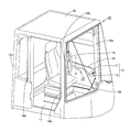
- a cab 20 is provided for an operator to enter the inside and operate the wheel loader 30.
- the cab 20 of the present embodiment includes a door opening / closing mechanism 10, a door 15, a driver's seat 16, a floor plate 17, a pair of front pillars 18a, a pair of center pillars 18b, A pair of rear pillars 18c and a roof 19 are mainly provided.
- a pair of front pillars 18a, a pair of center pillars 18b, and a pair of rear pillars 18c are erected.
- a roof 19 is supported on the upper ends of the pillars 18a, 18b, and 18c.
- a driver seat 16 for an operator to sit is disposed in the space surrounded by the floor plate 17, the pillars 18 a, 18 b, 18 c and the roof 19, a driver seat 16 for an operator to sit is disposed.
- a door 15 is disposed on the side of the driver's seat 16 (in the width direction of the vehicle body) and between the front pillar 18a and the center pillar 18b. The door 15 is used by an operator to enter and exit the cab 20 and is attached to the cab 20 so as to be openable and closable.
- a door opening / closing mechanism 10 for opening and closing the door 15 is attached to the door 15 and the front pillar 18a.
- the door opening / closing mechanism 10 mainly includes a lock assembly 13 having a catcher 11 and a striker 12, a hollow tube 1, and a handle 2.
- the one end of the hollow tube 1 is connected to a catcher 11, and the other end of the hollow tube 1 is connected to a tube 14 extending in the vertical direction of the vehicle body.
- the pipe 14 is attached to the door 15 at both ends.
- the catcher 11 has a claw portion (not shown), and this claw portion can be engaged with a bar member (not shown) of the striker 12.
- the handle 2 is attached to the hollow tube 1. By pushing the handle 2 toward the hollow tube 1, the engagement state between the claw portion of the catcher 11 and the bar member of the striker 12 can be released, and the door 15 can be opened.
- the door opening / closing mechanism 10 includes a fixture 3, a bolt 4, a rotating portion 5, and a wire in addition to the hollow tube 1 and the handle 2. 6.
- the hollow tube 1 has a pipe shape having a hollow space 1e inside, for example, a round pipe shape having a circular cross section.
- the hollow tube 1 has a hole 1a that connects the hollow space 1e and the outside.
- the handle 2 has a root portion 2a and a grip portion 2b.
- the root portion 2a and the grip portion 2b are integrally formed, and are formed by integral resin molding, for example.
- the root portion 2a is located over the hollow space 1e from the outside of the hollow tube 1 through the hole 1a.
- the root portion 2a has a hollow space side end portion 2a 1 and an outer side end portion 2a 2 which are opposed to each other in the height direction of the handle 2 (in the direction of arrow H in the figure).
- the root portion 2a has a pair of side surfaces 2ac that face each other in the width direction of the handle (in the direction of arrow W in the figure).
- the pair of side surfaces 2ac face each other between the hollow space side end 2a 1 and the outer side end 2a 2 so as to be parallel to each other.
- a hole 2ad is formed in each of the pair of side surfaces 2ac on the one end 2aa side of the root portion 2a along the length direction (arrow L direction in the drawing) of the hollow tube 1, and the pair of side surfaces on the other end 2ab side.
- a hole 2ae is formed in each 2ac.
- the width direction W is a direction orthogonal to the length direction L
- the height direction H is a direction orthogonal to both the length direction L and the width direction W.
- the grip portion 2b is located at the outer end 2a 2 of the root portion 2a, and is a portion that comes into contact with the operator's finger when the operator performs the door opening / closing operation. For this reason, on the surface opposite to the base portion 2a side of the grip portion 2b, gently wavy unevenness for attaching four fingers (index finger, middle finger, ring finger, little finger) is formed. In addition, since there is an inclined portion that is further away from the hollow tube 1 toward the front in front of the grip portion 2b, the operator can recognize the position of his / her finger relative to the grip portion 2b without looking at the handle. In the opening / closing operation of the door 15 (FIG. 2), the four fingers can be prevented from shifting from the grip portion 2b.
- the handle 2 is supported by the hollow tube 1 so as to be movable at least in the direction of being pushed into the hollow space 1e, and specifically has the following configuration.
- the fixture 3 is disposed in the hollow space 1 e of the hollow tube 1.
- the bolt 4 passes through the insertion hole 1 d of the hollow tube 1 and is screwed into the screw hole 3 b of the fixture 3.
- the fixture 3 is fixed to the hollow tube 1 in the hollow space 1 e by the bolt 4.
- This fixing tool 3 has a pair of shaft portions 3a protruding sideways from each of both side portions thereof.
- the pair of shaft portions 3a extends, for example, in a direction parallel to the tangent to the outer peripheral surface of the hollow tube 1 in a state where the fixture 3 is attached to the hollow tube 1. Yes.
- the fixture 3 is disposed between the pair of side surfaces 2ac of the root portion 2a.
- Each of the pair of shaft portions 3 a is inserted into the pair of holes 2 ae of the base portion 2 a and is disposed so as to extend along the width direction W of the handle 2.
- the handle 2 can be rotated around the pair of shaft portions 3a with respect to the hollow tube 1, and is supported by the hollow tube 1 so as to be movable in the direction of pushing into the hollow space 1e and in the opposite direction. Yes.
- the handle 2 is configured so as to be able to perform an operation such as pulling the wire 6 connected to the catcher 11 (FIG. 2) by the above movement operation (for example, a rotation operation). It has the structure as follows.
- the rotating part 5 is disposed between a pair of side surfaces 2ac of the root part 2a. Moreover, the rotation part 5 has a pair of axial part 5a which protrudes to the side from each of both side parts in the one end 5b side. Each of the pair of shaft portions 5 a is inserted into the pair of holes 2 ad of the root portion 2 a and is disposed so as to extend along the width direction W of the handle 2. Thereby, the rotation part 5 can rotate with respect to the handle
- the wire 6 is attached to the other end 5c side of the rotating portion 5, and the wire 6 extends in the hollow space 1e of the hollow tube 1 and reaches the catcher 11 (FIG. 2).
- the rotating unit 5 rotates with respect to the handle 2, an operation such as pulling the wire 6 is possible.
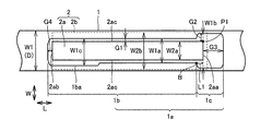
- hole 1a has a first hole 1c and a second hole 1b.
- the first hole portion 1 c is located at one end 2 aa of the root portion 2 a along the length direction L of the hollow tube 1.
- the second hole 1b is located on the other end 2ab side of the root 2a from the end of the first hole 1c.
- the dimension W2b in the width direction W of the grip part 2b of the handle 2 is larger than the dimension W2a in the width direction W of the root part 2a and larger than the dimension W1a in the width direction W of the second hole 1b.
- the dimension W1b in the width direction W of the first hole 1c is larger than the dimension W1a in the width direction W of the second hole 1b.
- the dimension G2 in the width direction W of the gap between the corner portion P1 and the first hole portion 1c at the one end 2aa of the root portion 2a is between the side surface 2ac of the root portion 2a and the second hole portion 1b. Is larger than the dimension G1 in the width direction W of the gap.
- the dimension W2b in the width direction W of the grip portion 2b is smaller than the dimension W1 (for example, the diameter D) in the width direction W of the hollow tube 1.
- the boundary B between the first hole 1c and the second hole 1b is located on the other end 2ab side by a predetermined length L1 from one end 2aa of the root portion 2a.
- the dimension W2b is preferably greater than or equal to the dimension W1b.
- the dimension G3 in the length direction L of the gap between the one end 2aa of the root portion 2a and the first hole 1c is the gap between the other end 2ab of the root portion 2a and the second hole 1b. It is larger than the dimension G4 in the length direction L.
- the insertion hole 1d is a long hole, and the length direction L of the gap between the one end 2aa of the root portion 2a and the first hole portion 1c even if the position of the handle is adjusted back and forth (L direction).
- the dimension G3 can secure a predetermined gap.
- a wide portion 1ba that widens the width of the second hole portion 1b may be formed on the other end side in the length direction L of the second hole portion 1b.
- the dimension W1c in the width direction W of the second hole 1b in the part where the wide part 1ba is formed is larger than the dimension W1a in the width direction W of the second hole 1b in the part where the wide part 1ba is not formed. Is also big.
- the handle 2 is not in contact with the inner peripheral surface of the hollow tube 1 before the handle 2 is pushed into the hollow space 1e side of the hollow tube 1. That is, the portion P2 located closest to the hollow space 1e at the one end 2aa of the root portion 2a is spaced apart from the portion P3 on the inner peripheral surface of the hollow tube 1 that intersects the rotation locus (one-dot chain line CC). Away. In this state, the other end 5 c side of the rotating portion 5 is in contact with the inner peripheral surface of the hollow tube 1.
- the handle 2 rotates until the portion P2 of the root portion 2a contacts the portion P3 of the inner peripheral surface of the hollow tube 1 by the above operation.
- the rotating portion 5 rotates with respect to the handle 2 around the shaft portion 5a.
- the other end 5 c side of the rotating unit 5 moves to the other end 2 ab side (left side in the drawing) in the length direction L while contacting the inner peripheral surface of the hollow tube 1.
- the wire 6 attached to the other end 5c side of the rotating part 5 is pulled to the other end 2ab side in the length direction L.
- claw part of the catcher 11 shown in FIG. 2 and the bar member of the striker 12 can be cancelled
- the grip portion 2b and the hollow tube 1 are located at a position where the grip portion 2b and the hollow tube 1 are closest to each other.
- the handle 2 is configured such that a gap G is generated therebetween. Further, the handle 2 is configured such that a gap G3 is generated at the front end of the handle 2 in the most depressed state.
- a height H2 (root portion 2a) from the root portion 2a at a position where the grip portion 2b and the hollow tube 1 are closest to each other.
- the dimension H2 in the direction from the hollow space 1e side to the outer side of the hollow tube 1 is larger than the dimension H1 (for example, diameter D) in the height direction H of the hollow tube 1.
- the one end 2aa of the root portion 2a has an inclination away from the rotation center O (shaft portion 3a) of the handle 2 as it approaches the grip portion 2b. That is, assuming a hypothetical curve CC that is equidistant from the rotation center O to the portion P2 located closest to the hollow space 1e at one end 2aa of the root portion 2a, one end of the root portion 2a is assumed. As the distance 2aa approaches the grip portion 2b from the portion P2, the inclination 2aa is inclined away from the virtual curve CC in the radial direction with the rotation center O as the center.
- One end 2aa of the root portion 2a is inclined at an angle ⁇ 2 of the one end 2aa of the root portion 2a with respect to the virtual straight line EE extending in the length direction L before the handle 2 is pushed into the hollow space 1e. Is preferably less than 90 °.
- the grip portion 2b has an inclined portion located on the one end 2aa side of the root portion 2a and an uneven portion located on the other end 2ab side of the root portion 2a.
- This inclined part has an inclination which leaves
- the inclined portion is inclined at an angle ⁇ 1 of less than 90 ° with respect to the boundary line between the root portion 2a and the uneven portion of the grip portion 2b.
- the handle 2 is supported by the hollow tube 1 so as to be movable in the direction of being pushed into the hollow space 1e.
- the operator grasps both the hollow tube 1 and the handle 2 and pushes the handle 2 toward the hollow space 1e. Can be opened and closed.
- the width W of the grip portion 2b is larger than the dimension W2a of the root portion 2a in the width direction W and larger than the width W of the second hole 1b in the width direction W1a. Therefore, as shown in FIG. 6C, when the operator pushes both the hollow tube 1 and the handle 2 to push the handle 2 into the hollow space 1e, the grip portion 2b has a large width W2b. It becomes difficult for a finger or palm to enter between the grip portion 2 b and the hollow tube 1. This makes it difficult for an operator to put a finger or palm in the gap between the root 2a of the handle 2 and the hole 1a of the hollow tube 1.
- the dimension W1b in the width direction W of the first hole 1c is larger than the dimension W1a in the width direction W of the second hole 1b.
- the dimension G2 of the gap in the width direction W can be increased, and the operator's finger can be prevented from being caught at this portion.
- the dimension G1 of the gap in the width direction W between the root part 2a and the second hole 1b can be reduced. For this reason, rattling of the handle 2 with respect to the hollow tube 1 can be suppressed.
- the hollow tube 1 is a round pipe.
- the operator's finger and palm are the round pipe hollow tube 1 as shown by the arrows in the figure. It becomes easy to escape from between the grip part 2b and the hollow tube 1 along the outer peripheral surface. For this reason, it becomes more difficult for an operator to pinch a finger or a palm into the gap between the root portion 2a of the handle 2 and the hole 1a of the hollow tube 1.
- the dimension W2b in the width direction W of the grip portion 2b is smaller than the dimension W1 in the width direction W of the hollow tube 1.
- the grip portion 2b and the hollow tube 1 are located at a position where the grip portion 2b and the hollow tube 1 are closest to each other. There is a gap G between them. Thereby, even if the handle 2 is pushed most into the hollow space 1e side, the grip portion 2b and the hollow tube 1 do not contact each other. Further, the handle 2 is configured such that a gap G3 is generated at the front end of the handle 2 in the most depressed state.
- the height H2 of the root portion 2a from the hollow space 1e side toward the outside is larger than the dimension H1 (for example, diameter D) in the height direction H of the hollow tube 1.
- the root portion 2a is rotatably supported by the hollow tube 1 on the other end 2ab side in the length direction L, and the one end 2aa of the root portion 2a is supported by the grip portion 2b.
- the grip portion 2b has an inclined portion at one end that is separated from the hollow tube 1 toward the one end 2aa from the other end 2ab side.
- the operator can recognize the position of his / her index finger with respect to the grip portion 2b of the handle 2 without looking at the inclined portion at one end. Further, by pushing the inclined portion at one end farthest from the other end side that becomes the rotation center O into the hollow space side with the index finger, the handle can be operated with a small operating force.
Abstract
ハンドル(2)は、中空空間(1e)側に押し込む方向に移動可能に中空管(1)に支持されている。中空管(1)の中空空間(1e)に通じる孔(1a)は、中空管(1)の長さ方向Lに沿う根元部(2a)の一方端(2aa)に位置する第1の孔部(1c)と、第1の孔部(1c)から長さ方向Lの他方端(2ab)側まで位置する第2の孔部(1b)とを有している。ハンドル(2)の握り部(2b)の幅方向Wの寸法W2bは、ハンドル(2)の根元部(2a)の幅方向Wの寸法W2aよりも大きく、かつ第2の孔部(1b)の幅方向Wの寸法W1aよりも大きい。これにより、簡易な動作でドアを開閉でき、かつオペレータがドアの開閉動作時に指や手の平を挟みにくい建設機械用キャブおよびそれを備えた建設機械が得られる。
Description
本発明は、建設機械用キャブおよび建設機械に関し、特に、ドアと、ドアの開閉のためのドア開閉機構とを備えた建設機械用キャブおよびそれを備えた建設機械に関するものである。
作業車両のドアハンドルは、たとえば米国特許出願公開第2010/0045052号(特許文献1)に開示されている。
この米国特許出願公開第2010/0045052号には、農業機械のような車両の内側からオペレータが、横断チューブに設けられた遠隔作動ボタンを押すことによりドアロックを解除できるドアロック機構が記載されている。これによりオペレータは、横断チューブとともに遠隔作動ボタンを握ることで遠隔作動ボタンを横断チューブ内に押し込むことができ、簡易な動作でドアのロック解除などをすることができる。
しかしながら上記のドアロック機構では、横断チューブの孔とその孔内に差し込まれた遠隔作動ボタンとの間の隙間にオペレータが指や手の平を挟むおそれがある。
本発明は、上記の課題に鑑みてなされたものであり、その目的は、簡易な動作でドアを開閉でき、かつオペレータがドアの開閉動作時に指や手の平を挟みにくい建設機械用キャブおよびそれを備えた建設機械を提供することである。
本発明の建設機械用キャブは、ドアと、そのドアの開閉のためのドア開閉機構とを備えた建設機械用キャブである。ドア開閉機構は、中空管と、ハンドルとを含んでいる。中空管は、内部に中空空間を有し、かつ中空空間と外部とをつなぐ孔を有している。ハンドルは、孔を通じて外部から中空空間内に亘って位置する根元部と、その根元部の中空空間側の端部に対向する外部側の端部に位置する握り部とを有し、かつ中空空間側に押し込む方向に移動可能に中空管に支持されている。孔は、中空管の長さ方向に沿う根元部の一方端に位置する第1の孔部と、第1の孔部から長さ方向の他方端側まで位置する第2の孔部とを有している。握り部の長さ方向に直交する幅方向の寸法は、根元部の幅方向の寸法よりも大きく、かつ第2の孔部の幅方向の寸法よりも大きい。
本発明の建設機械用キャブによれば、ハンドルは中空空間側に押し込む方向に移動可能に中空管に支持されている。これにより、オペレータは中空管とハンドルとの双方を握り込んでハンドルを中空空間側に押し込むという簡易な動作でドアの開閉を行うことができる。
また握り部の幅方向の寸法が根元部の幅方向の寸法よりも大きく、かつ第2の孔部の幅方向の寸法よりも大きい。このため、オペレータが中空管とハンドルとの双方を握り込むことでハンドルを中空空間側に押し込んだ場合、握り部の大きな幅のため指や手の平が握り部と中空管との間に入り込みにくくなる。これによりハンドルの根元部と中空管の孔との隙間にオペレータが指や手の平を挟みにくくなる。
上記の建設機械用キャブにおいて、第1の孔部の幅方向の寸法は、第2の孔部の幅方向の寸法よりも大きい。
第1の孔部の幅方向の寸法を大きくすることにより、オペレータの指が挟まれやすい根元部の一方端における角部と第1の孔部との隙間を大きくすることができ、この部分でオペレータの指が挟まれることを抑制することができる。また第2の孔部の幅方向の寸法を小さくすることにより根元部と第2の孔との幅方向の隙間を小さくできるため、隙間が大きくなることによるハンドルの中空管に対するがたつきを抑制することができる。
上記の建設機械用キャブにおいて、中空管は丸パイプよりなっている。
これにより、オペレータの指や手の平は、丸パイプの中空管の外周面に沿って握り部と中空管との間から逃げやすくなる。このためハンドルの根元部と中空管の孔との隙間にオペレータが指や手の平をさらに挟みにくくなる。
これにより、オペレータの指や手の平は、丸パイプの中空管の外周面に沿って握り部と中空管との間から逃げやすくなる。このためハンドルの根元部と中空管の孔との隙間にオペレータが指や手の平をさらに挟みにくくなる。
上記の建設機械用キャブにおいて、握り部の幅方向の寸法は、中空管の幅方向の寸法よりも小さい。
これによりオペレータが中空管とハンドルとの双方を握り込んだときにハンドルを握りやすくなる。
上記の建設機械用キャブにおいて、ハンドルが中空空間側に最も押し込まれた状態において、握り部と中空管とが互いに最も近づく箇所で握り部と中空管との間に隙間がある。
これによりハンドルを中空空間側に最も押し込んだ状態でも握り部と中空管とが互いに接触することはない。
上記の建設機械用キャブにおいて、根元部の中空空間側から外部側へ向かう方向の寸法が、中空管の高さ方向の寸法よりも大きい。
これによりハンドルを中空空間側に最も押し込んだ状態でも握り部と中空管とが互いに接触することはない。
上記の建設機械用キャブにおいて、根元部は長さ方向の他方端側において回動可能に中空管に支持されており、根元部の一方端は握り部に近づくほどハンドルの回動中心から離れる傾斜を有している。
これにより根元部の一方端に指を掛けてハンドルを押し込む操作をする場合でも、ハンドルを押し込むほどにその一方端に掛けた指が根元部の傾斜に沿って回動中心から離れていく。このように根元部とその根元部の長さ方向に位置する孔との隙間から指が逃げるように移動するため、その隙間に指が挟まれにくくなる。
上記の建設機械用キャブにおいて、握り部は、他方端側から一方端に向かうほど中空管から離れる傾斜部を一方端に有している。
オペレータはこの一方端の傾斜部によりハンドルの握り部に対する自己の人差し指の位置を目視することなく認識することが可能となる。また回動中心となる他方端側から最も離れた一方端の傾斜部を人差し指で中空空間側へ押し込むことにより、小さな操作力でハンドルを操作することが可能となる。
本発明の建設機械は、上記のいずれかに記載の建設機械用キャブを備えている。
本発明の建設機械によれば、簡易な動作でドアを開閉でき、かつオペレータがドアの開閉動作時に指や手の平を挟みにくくなる。
本発明の建設機械によれば、簡易な動作でドアを開閉でき、かつオペレータがドアの開閉動作時に指や手の平を挟みにくくなる。
以上説明したように本発明によれば、簡易な動作でドアを開閉でき、かつオペレータがドアの開閉動作時に指や手の平を挟みにくい建設機械用キャブおよびそれを備えた建設機械を実現することができる。
以下、本発明の実施の形態について図に基づいて説明する。
まず本発明の実施の形態1における建設機械の一例としてホイールローダの構成について図1を用いて説明するが、本発明は油圧ショベル、ブルドーザなどのドア開閉機構を有するキャブを備えた建設機械に適用可能である。
まず本発明の実施の形態1における建設機械の一例としてホイールローダの構成について図1を用いて説明するが、本発明は油圧ショベル、ブルドーザなどのドア開閉機構を有するキャブを備えた建設機械に適用可能である。
図1を参照して、本実施の形態のホイールローダ30は、前部フレーム21と、後部車体22と、作業機23とを主に有している。前部フレーム21の両側部の各々には前輪24aが取付けられており、後部車体22の両側部の各々には後輪24bが取付けられている。
前部フレーム21と後部車体22とは、センタピン(図示せず)により左右に揺動自在に取付けられており、アーティキュレート構造を構成している。つまり前部フレーム21と後部車体22とは、左右一対のステアリングシリンダ(図示せず)により連結されており、この左右のステアリングシリンダを伸縮することにより前部フレーム21と後部車体22とはセンタピンを中心として左右に揺動し、操向するように構成されている。この前部フレーム21と後部車体22とによりホイールローダ30の車体が構成されている。
前部フレーム21の前方には作業機23が取付けられている。作業機23は、前部フレーム21に基端部を揺動自在に取付けられたブーム23aと、ブーム23aの先端部に揺動自在に取付けられたバケット23bとを有している。前部フレーム21とブーム23aとは一対のブームシリンダ23cにより連結されており、一対のブームシリンダ23cを伸縮することによりブーム23aが揺動するよう構成されている。
また作業機23は、そのほぼ中央部においてブーム23aに揺動自在に支持されているベルクランク23dと、ベルクランク23dの基端部と前部フレーム21とを連結するバケットシリンダ23eと、ベルクランク23dの先端部とバケット23bとを連結するリンク23fとを有している。バケットシリンダ23eを伸縮することにより、バケット23bが揺動するように構成されている。
後部車体22の後方にはエンジン室22bが配置されており、このエンジン室22bの前方には作動油タンク22aが配置されている。作動油タンク22aの前方には、オペレーターが内部に入ってホイールローダ30を操作するためのキャブ20が設けられている。
次に、図1のホイールローダ30に用いられるキャブ20であって、本発明の一実施の形態における建設機械用キャブ20の構成について図2を用いて説明する。
図2を参照して、本実施の形態のキャブ20は、ドア開閉機構10と、ドア15と、運転席16と、フロアプレート17と、一対のフロントピラー18aと、一対のセンターピラー18bと、一対のリアピラー18cと、ルーフ19とを主に有している。
フロアプレート17から、一対のフロントピラー18a、一対のセンターピラー18bおよび一対のリアピラー18cがそれぞれ立設している。これらの各ピラー18a、18b、18cの上端にはルーフ19が支持されている。
フロアプレート17、各ピラー18a、18b、18cおよびルーフ19により取り囲まれた空間内に、オペレータが着座するための運転席16が配置されている。運転席16の側部(車体の幅方向)であって、フロントピラー18aとセンターピラー18bとの間にはドア15が配置されている。このドア15は、オペレータがキャブ20へ出入りするためのものであり、キャブ20に対して開閉可能に取り付けられている。
ドア15およびフロントピラー18aには、ドア15の開閉操作を行うためのドア開閉機構10が取り付けられている。ドア開閉機構10は、キャッチャー11およびストライカー12を有するロックアセンブリ13と、中空管1と、ハンドル2とを主に有している。
中空管1の一方端はキャッチャー11に接続されており、中空管1の他方端は車体の上下方向に延びる管14に接続されている。この管14は両端部においてドア15に取付けられている。キャッチャー11は爪部(図示せず)を有しており、この爪部はストライカー12のバー部材(図示せず)に係合可能である。
ハンドル2は中空管1に取付けられている。このハンドル2を中空管1側に押し込むことにより、キャッチャー11の爪部とストライカー12のバー部材との係合状態を解除することができ、ドア15を開くことができる。
次に、中空管とハンドルとの取付構造などについて図3(A)、(B)および図4を用いて説明する。
図3(A)および図3(B)を参照して、上記のドア開閉機構10は、中空管1およびハンドル2以外に、固定具3と、ボルト4と、回動部5と、ワイヤー6とをさらに有している。
中空管1は、内部に中空空間1eを有するパイプ形状を有しており、たとえば横断面形状が円形の丸パイプ形状を有している。この中空管1は、中空空間1eと外部とをつなぐ孔1aを有している。
ハンドル2は、根元部2aと、握り部2bとを有している。根元部2aと握り部2bとは一体で形成されており、たとえば一体の樹脂成形により構成されている。根元部2aは、孔1aを通じて中空管1の外部から中空空間1e内に亘って位置している。この根元部2aは、ハンドル2の高さ方向(図中矢印H方向)に互いに対向する中空空間側端部2a1と外部側端部2a2とを有している。
また根元部2aは、ハンドルの幅方向(図中矢印W方向)に互いに対向する一対の側面2acを有している。一対の側面2acは、中空空間側端部2a1と外部側端部2a2との間で互いに平行となるように対向している。
中空管1の長さ方向(図中矢印L方向)に沿う根元部2aの一方端2aa側における一対の側面2acの各々には孔2adが形成されており、他方端2ab側における一対の側面2acの各々には孔2aeが形成されている。なお上記幅方向Wは上記長さ方向Lに直交する方向であり、上記高さ方向Hは上記長さ方向Lおよび上記幅方向Wの双方に直交する方向である。
握り部2bは根元部2aの外部側端部2a2に位置しており、オペレータがドアの開閉操作を行う時にオペレータの指に接触する部分である。このため、握り部2bの根元部2a側とは反対側の面には、4本の指(人差し指、中指、薬指、小指)を添えるための緩やかな波状の凹凸が形成されている。また、握り部2bの前方には前方に向かうほど中空管1から離れる傾斜部があることにより、オペレータはハンドルを目視せずとも握り部2bに対する自己の指の位置を認識することができるとともに、ドア15(図2)の開閉操作時において上記4本の指が握り部2bからずれることを抑制することができる。
上記ハンドル2は、少なくとも中空空間1e側に押し込む方向に移動可能なように中空管1に支持されており、具体的には以下のような構成を有している。
まず固定具3が中空管1の中空空間1e内に配置されている。ボルト4は、中空管1の挿通孔1dを貫通して固定具3のネジ孔3bに螺合されている。これにより固定具3はボルト4によって中空空間1e内で中空管1に固定されている。
この固定具3は、その両側部の各々から側方に突き出す一対の軸部3aを有している。一対の軸部3aは、中空管1がたとえば丸パイプである場合、固定具3が中空管1に取付けられた状態においてたとえば中空管1の外周面の接線に平行な方向に延びている。
固定具3は根元部2aの一対の側面2acの間に配置されている。また一対の軸部3aのそれぞれは根元部2aの一対の孔2ae内に挿入されており、ハンドル2の幅方向Wに沿って延びるように配置されている。これによりハンドル2は、中空管1に対して一対の軸部3aを中心に回動可能であり、中空空間1e側に押し込む方向およびその逆方向に移動可能に中空管1に支持されている。
また上記ハンドル2は、上記の移動動作(たとえば回動動作)により、キャッチャー11(図2)に接続されたワイヤー6を引っ張るなどの操作が可能なように構成されており、具体的には以下のような構成を有している。
まず回動部5は根元部2aの一対の側面2acの間に配置されている。また回動部5は、その一方端5b側において両側部の各々から側方に突き出す一対の軸部5aを有している。一対の軸部5aのそれぞれは根元部2aの一対の孔2ad内に挿入されており、ハンドル2の幅方向Wに沿って延びるように配置されている。これにより回動部5は、ハンドル2に対して一対の軸部5aを中心に回動可能である。
この回動部5の他方端5c側にはワイヤー6が取り付けられており、ワイヤー6は中空管1の中空空間1e内を延びてキャッチャー11(図2)に達している。この回動部5がハンドル2に対して回動することにより、ワイヤー6を引っ張るなどの操作が可能である。
次に、孔1aの形状、各部の寸法などについて図4を用いて説明する。
図4を参照して、孔1aは、第1の孔部1cと、第2の孔部1bとを有している。第1の孔部1cは、中空管1の長さ方向Lに沿う根元部2aの一方端2aaに位置している。第2の孔部1bは、その第1の孔部1cの端部から根元部2aの他方端2ab側に位置している。
図4を参照して、孔1aは、第1の孔部1cと、第2の孔部1bとを有している。第1の孔部1cは、中空管1の長さ方向Lに沿う根元部2aの一方端2aaに位置している。第2の孔部1bは、その第1の孔部1cの端部から根元部2aの他方端2ab側に位置している。
ハンドル2の握り部2bの上記幅方向Wの寸法W2bは、根元部2aの幅方向Wの寸法W2aよりも大きく、かつ第2の孔部1bの幅方向Wの寸法W1aよりも大きい。
また第1の孔部1cの幅方向Wの寸法W1bは、第2の孔部1bの幅方向Wの寸法W1aよりも大きい。これにより根元部2aの一方端2aaにおける角部P1と第1の孔部1cとの間における隙間の幅方向Wの寸法G2は、根元部2aの側面2acと第2の孔部1bとの間における隙間の幅方向Wの寸法G1よりも大きい。また握り部2bの幅方向Wの寸法W2bは、中空管1の幅方向Wの寸法W1(たとえば直径D)よりも小さい。なお第1の孔部1cと第2の孔部1bとの境界Bは、根元部2aの一方端2aaから所定長さL1だけ他方端2ab側に位置している。寸法W2bは寸法W1b以上であることが好ましい。
また根元部2aの一方端2aaと第1の孔部1cとの間における隙間の上記長さ方向Lの寸法G3は、根元部2aの他方端2abと第2の孔部1bとの間における隙間の長さ方向Lの寸法G4よりも大きい。前記挿通孔1dは長孔であり、ハンドルの位置を前後(L方向)に位置調整しても根元部2aの一方端2aaと第1の孔部1cとの間における隙間の上記長さ方向Lの寸法G3は所定の隙間を確保できる。
また第2の孔部1bの上記長さ方向Lの他方端側には、第2の孔部1bの幅を広げるような幅広部1baが形成されていてもよい。これにより幅広部1baが形成された部分の第2の孔部1bの幅方向Wの寸法W1cは、幅広部1baが形成されていない部分の第2の孔部1bの幅方向Wの寸法W1aよりも大きい。この幅広部1baを設けたことによりハンドル2の中空管1への組み付けが容易となる。
次に、本実施の形態のドア開閉機構10の動作について図5(A)および図5(B)を用いて説明する。
図5(A)を参照して、ハンドル2を中空管1の中空空間1e側に押し込む前の状態においては、ハンドル2は中空管1の内周面とは接していない。つまり根元部2aの一方端2aaにおける最も中空空間1e側に位置する部分P2は、その回動軌跡(一点鎖線C-C)と交差する中空管1の内周面の部分P3と間隔をあけて離れている。またこの状態において回動部5の他方端5c側は中空管1の内周面に当接している。
この状態からオペレータが中空管1とハンドル2との双方を握り込むことにより、ハンドル2に図中太矢印F方向に力が加わる。このF方向の力により、ハンドル2が軸部3aを中心Oとして中空管1の中空空間1e側に押し込まれる方向に回動する。
図5(B)を参照して、上記の操作により、根元部2aの部分P2が中空管1の内周面の部分P3に当接するまでハンドル2が回動する。この際、回動部5はハンドル2に対して軸部5aを中心として回動する。この回動部5の回動により、回動部5の他方端5c側は中空管1の内周面に当接しながら長さ方向Lの他方端2ab側(図中左側)に移動する。これにより回動部5の他方端5c側に取付けられたワイヤー6が上記長さ方向Lの他方端2ab側に引っ張られる。これにより、図2に示すキャッチャー11の爪部とストライカー12のバー部材との係合状態を解除することができ、ドア15を開くことができる。
次に、本実施の形態のドア開閉機構10の好ましい構成について図5(A)および図5(B)を用いて説明する。
図5(B)を参照して、ハンドル2が中空空間1e側に最も押し込まれた状態において、握り部2bと中空管1とが互いに最も近づく箇所で握り部2bと中空管1との間に隙間Gが生じるようにハンドル2が構成されている。また、最も押し込まれた状態において、ハンドル2の前端においても、隙間G3が生じるようにハンドル2が構成されている。
図5(A)を参照して、上記の隙間Gを生じさせるため、具体的には握り部2bと中空管1とが互いに最も近づく箇所における根元部2aからの高さH2(根元部2aの中空空間1e側から中空管1の外部側へ向かう方向の寸法H2)が、中空管1の高さ方向Hの寸法H1(たとえば直径D)よりも大きくなっている。
根元部2aの一方端2aaは、握り部2bに近づくほどハンドル2の回動中心O(軸部3a)から離れる傾斜を有している。つまり、回動中心Oから根元部2aの一方端2aaにおける最も中空空間1e側に位置する部分P2までの距離と等距離にある仮想の曲線C-Cを想定した場合、根元部2aの一方端2aaは上記部分P2から握り部2bに近づくほど、この仮想の曲線C-Cから回動中心Oを中心とする半径方向に離れる傾斜を有している。
また根元部2aの一方端2aaは、ハンドル2が中空空間1e側に押し込まれる前の状態において、上記長さ方向Lに延びる仮想の直線E-Eに対する根元部2aの一方端2aaの傾斜角度θ2は90°未満であることが好ましい。
また握り部2bは、根元部2aの一方端2aa側の上に位置する傾斜部と、根元部2aの他方端2ab側の上に位置する凹凸部とを有している。この傾斜部は、長さ方向Lに沿う根元部2aの他方端2ab側から一方端2aaに向かうほど中空管1から離れる傾斜を有している。この傾斜部は、根元部2aと握り部2bの凹凸部との境界線に対して90°未満の角度θ1で傾斜している。
次に、本実施の形態の作用効果について説明する。
本実施の形態によれば、図5(A)および図5(B)に示すようにハンドル2は中空空間1e側に押し込む方向に移動可能に中空管1に支持されている。これにより、オペレータは図6(A)または図6(B)に示すように中空管1とハンドル2との双方を握り込んでハンドル2を中空空間1e側に押し込むという簡易な動作でドア15の開閉を行うことができる。
本実施の形態によれば、図5(A)および図5(B)に示すようにハンドル2は中空空間1e側に押し込む方向に移動可能に中空管1に支持されている。これにより、オペレータは図6(A)または図6(B)に示すように中空管1とハンドル2との双方を握り込んでハンドル2を中空空間1e側に押し込むという簡易な動作でドア15の開閉を行うことができる。
また図4に示すように握り部2bの幅方向Wの寸法W2bが根元部2aの幅方向Wの寸法W2aよりも大きく、かつ第2の孔部1bの幅方向Wの寸法W1aよりも大きい。このため、図6(C)に示すようにオペレータが中空管1とハンドル2との双方を握り込むことでハンドル2を中空空間1e側に押し込んだ場合、握り部2bの大きな幅W2bのため指や手の平が握り部2bと中空管1との間に入り込みにくくなる。これによりハンドル2の根元部2aと中空管1の孔1aとの隙間にオペレータが指や手の平を挟みにくくなる。
また図4に示すように第1の孔部1cの幅方向Wの寸法W1bは、第2の孔部1bの幅方向Wの寸法W1aよりも大きい。このように第1の孔部1cの幅方向Wの寸法W1bを大きくすることにより、オペレータの指が挟まれやすい根元部2aの一方端2aaにおける角部P1と第1の孔部1cと間の隙間の幅方向Wの寸法G2を大きくすることができ、この部分でオペレータの指が挟まれることを抑制することができる。また第2の孔部1bの幅方向Wの寸法W1aを小さくすることにより根元部2aと第2の孔部1bとの間の幅方向Wの隙間の寸法G1を小さくできる。このため、ハンドル2の中空管1に対するがたつきを抑制することができる。
また図3(A)、図3(B)などに示すように中空管1は丸パイプよりなっている。これにより図6(C)に示すようにオペレータが中空管1とハンドル2との双方を握り込んだときに、オペレータの指や手の平は図中矢印で示すように丸パイプの中空管1の外周面に沿って握り部2bと中空管1との間から逃げやすくなる。このためハンドル2の根元部2aと中空管1の孔1aとの間の隙間にオペレータが指や手の平をさらに挟みにくくなる。
また図4に示すように握り部2bの幅方向Wの寸法W2bは、中空管1の幅方向Wの寸法W1よりも小さい。これにより図6(A)、(B)、(C)に示すようにオペレータが中空管1とハンドル2との双方を握り込んだときにハンドル2を握りやすくなる。
また図5(B)に示すようにハンドル2が中空空間1e側に最も押し込まれた状態において、握り部2bと中空管1とが互いに最も近づく箇所で握り部2bと中空管1との間に隙間Gがある。これによりハンドル2を中空空間1e側に最も押し込んだ状態でも握り部2bと中空管1とが互いに接触することはない。また、最も押し込まれた状態において、ハンドル2の前端においても、隙間G3が生じるようにハンドル2が構成されている。
また図5(A)に示すように根元部2aの中空空間1e側から外部側へ向かう高さH2が、中空管1の高さ方向Hの寸法H1(たとえば直径D)よりも大きい。これによりハンドル2を中空空間1e側に最も押し込んだ状態でも握り部2bと中空管1とが互いに接触することはない。
また図5(A)に示すように根元部2aは長さ方向Lの他方端2ab側において回動可能に中空管1に支持されており、根元部2aの一方端2aaは握り部2bに近づくほどハンドル2の回動中心Oから離れる傾斜を有している。これにより図6(B)に示すように根元部2aの一方端2aaに指(人差し指)を掛けてハンドル2を図中矢印S2で示す方向に押し込む操作する場合でも、ハンドル2を押し込むほどにその一方端2aaに掛けた指が根元部2aの一方端2aaの傾斜に沿って図中矢印S1に示す方向に回動中心から離れていく。このように根元部2aとその根元部2aの長さ方向Lに位置する孔との隙間から指が逃げるように移動するため、その隙間に指が挟まれにくくなる。
また図5(A)に示すように握り部2bは、他方端2ab側から一方端2aaに向かうほど中空管1から離れる傾斜部を一方端に有している。オペレータはこの一方端の傾斜部によりハンドル2の握り部2bに対する自己の人差し指の位置を目視することなく認識することが可能となる。また回動中心Oとなる他方端側から最も離れた一方端の傾斜部を人差し指で中空空間側へ押し込むことにより、小さな操作力でハンドルを操作することが可能となる。
今回開示された実施の形態はすべての点で例示であって制限的なものではないと考えられるべきである。本発明の範囲は上記した説明ではなくて請求の範囲によって示され、請求の範囲と均等の意味および範囲内でのすべての変更が含まれることが意図される。
1 中空管、1a 孔、1b 第2の孔部、1ba 幅広部、1c 第1の孔部、1d 挿通孔、1e 中空空間、2 ハンドル、2a 根元部、2a1 中空空間側端部、2a2 外部側端部、2aa,5b 一方端、2ab,5c 他方端、2ad,2ae 孔、2b 握り部、3 固定具、3a,5a 軸部、3b ネジ孔、4 ボルト、5 回動部、6 ワイヤー、10 ドア開閉機構、11 キャッチャー、12 ストライカー、13 ロックアセンブリ、14 管、15 ドア、16 運転席、17 フロアプレート、18a フロントピラー、18b センターピラー、18c リアピラー、19 ルーフ、20 建設機械用キャブ、21 前部フレーム、22 後部車体、22a 作動油タンク、22b エンジン室、23 作業機、23a ブーム、23b バケット、23c ブームシリンダ、23d ベルクランク、23e バケットシリンダ、23f リンク、24a 前輪、24b 後輪、30 ホイールローダ。
Claims (9)
- ドアと、前記ドアの開閉のためのドア開閉機構とを備えた建設機械用キャブであって、
前記ドア開閉機構は、
内部に中空空間を有し、かつ前記中空空間と外部とをつなぐ孔を有する中空管と、
前記孔を通じて前記外部から前記中空空間内に亘って位置する根元部と、前記根元部の前記中空空間側の端部に対向する前記外部側の端部に位置する握り部とを有し、かつ前記中空空間側に押し込む方向に移動可能に前記中空管に支持されたハンドルとを含み、
前記孔は、前記中空管の長さ方向に沿う前記根元部の一方端に位置する第1の孔部と、前記第1の孔部から前記長さ方向の他方端側まで位置する第2の孔部とを有し、
前記握り部の前記長さ方向に直交する幅方向の寸法は、前記根元部の前記幅方向の寸法よりも大きく、かつ前記第2の孔部の前記幅方向の寸法よりも大きい、建設機械用キャブ。 - 前記第1の孔部の前記幅方向の寸法は、前記第2の孔部の前記幅方向の寸法よりも大きい、請求項1に記載の建設機械用キャブ。
- 前記中空管は丸パイプよりなっている、請求項1または2に記載の建設機械用キャブ。
- 前記握り部の前記幅方向の寸法は、前記中空管の前記幅方向の寸法よりも小さい、請求項1~3のいずれか1項に記載の建設機械用キャブ。
- 前記ハンドルが前記中空空間側に最も押し込まれた状態において、前記握り部と前記中空管とが互いに最も近づく箇所で前記握り部と前記中空管との間に隙間がある、請求項1~4のいずれか1項に記載の建設機械用キャブ。
- 前記根元部の前記中空空間側から前記外部側へ向かう高さ方向の寸法が、前記中空管の前記高さ方向の寸法よりも大きい、請求項1~5のいずれか1項に記載の建設機械用キャブ。
- 前記根元部は前記長さ方向の前記他方端側において回動可能に前記中空管に支持されており、
前記根元部の前記一方端は、前記握り部に近づくほど前記ハンドルの回動中心から離れる傾斜を有している、請求項1~6のいずれか1項に記載の建設機械用キャブ。 - 前記握り部は、前記他方端側から前記一方端に向かうほど前記中空管から離れる傾斜部を前記一方端に有している、請求項1~7のいずれか1項に記載の建設機械用キャブ。
- 請求項1~8のいずれか1項に記載の前記建設機械用キャブを備えた、建設機械。
Priority Applications (3)
| Application Number | Priority Date | Filing Date | Title |
|---|---|---|---|
| CN201380001013.4A CN104126046B (zh) | 2013-02-22 | 2013-03-12 | 用于工程机械的驾驶室和工程机械 |
| US14/003,328 US9221319B2 (en) | 2013-02-22 | 2013-03-12 | Cab for construction machine and construction machine |
| EP13759110.3A EP2792821B1 (en) | 2013-02-22 | 2013-03-12 | Construction machinery cab and construction machinery |
Applications Claiming Priority (2)
| Application Number | Priority Date | Filing Date | Title |
|---|---|---|---|
| JP2013-033323 | 2013-02-22 | ||
| JP2013033323A JP5319029B1 (ja) | 2013-02-22 | 2013-02-22 | 建設機械用キャブおよび建設機械 |
Publications (1)
| Publication Number | Publication Date |
|---|---|
| WO2014128978A1 true WO2014128978A1 (ja) | 2014-08-28 |
Family
ID=49595805
Family Applications (1)
| Application Number | Title | Priority Date | Filing Date |
|---|---|---|---|
| PCT/JP2013/056772 WO2014128978A1 (ja) | 2013-02-22 | 2013-03-12 | 建設機械用キャブおよび建設機械 |
Country Status (4)
| Country | Link |
|---|---|
| EP (1) | EP2792821B1 (ja) |
| JP (1) | JP5319029B1 (ja) |
| CN (1) | CN104126046B (ja) |
| WO (1) | WO2014128978A1 (ja) |
Families Citing this family (5)
| Publication number | Priority date | Publication date | Assignee | Title |
|---|---|---|---|---|
| JP2016008035A (ja) * | 2014-06-26 | 2016-01-18 | ヤンマー株式会社 | 作業車両 |
| JP2016008034A (ja) * | 2014-06-26 | 2016-01-18 | ヤンマー株式会社 | 作業車両 |
| JP6566667B2 (ja) * | 2015-03-12 | 2019-08-28 | 株式会社アルファ | 車両のハンドル装置 |
| JP7119323B2 (ja) * | 2017-09-25 | 2022-08-17 | 株式会社アイシン | 車両用アウトサイドハンドル装置 |
| CN109610959B (zh) * | 2018-10-31 | 2021-07-02 | 广西柳工机械股份有限公司 | 驾驶室门限位锁双控解锁装置 |
Citations (2)
| Publication number | Priority date | Publication date | Assignee | Title |
|---|---|---|---|---|
| JPS6328756U (ja) * | 1986-08-09 | 1988-02-25 | ||
| US20100045052A1 (en) | 2007-04-12 | 2010-02-25 | D. La Porte Soehne Gmbh | Near and remote controlled vehicle door lock |
Family Cites Families (7)
| Publication number | Priority date | Publication date | Assignee | Title |
|---|---|---|---|---|
| US3767238A (en) * | 1972-05-04 | 1973-10-23 | Von Duperin Inc | Push plate panic exit device |
| JPH0610041Y2 (ja) * | 1987-08-31 | 1994-03-16 | 国産金属工業株式会社 | 自動車用アウトドアハンドル |
| DE19952012A1 (de) * | 1999-10-28 | 2001-05-03 | Porte Soehne D La | Türschloß, insbesondere für Traktoren |
| US7198308B2 (en) * | 2004-03-29 | 2007-04-03 | Tri/Mark Corporation | Operating mechanism for a movable closure element |
| US7137662B2 (en) * | 2004-04-30 | 2006-11-21 | Takeuchi Mfg., Co., Ltd. | Operator cab for construction machine |
| US8011699B2 (en) * | 2007-10-04 | 2011-09-06 | Tri Mark Corp | Cable actuated latch system |
| KR101625677B1 (ko) * | 2009-12-08 | 2016-05-31 | 두산인프라코어 주식회사 | 건설 중장비용 전방 도어의 개폐 제어 장치 |
-
2013
- 2013-02-22 JP JP2013033323A patent/JP5319029B1/ja active Active
- 2013-03-12 CN CN201380001013.4A patent/CN104126046B/zh active Active
- 2013-03-12 WO PCT/JP2013/056772 patent/WO2014128978A1/ja active Application Filing
- 2013-03-12 EP EP13759110.3A patent/EP2792821B1/en active Active
Patent Citations (2)
| Publication number | Priority date | Publication date | Assignee | Title |
|---|---|---|---|---|
| JPS6328756U (ja) * | 1986-08-09 | 1988-02-25 | ||
| US20100045052A1 (en) | 2007-04-12 | 2010-02-25 | D. La Porte Soehne Gmbh | Near and remote controlled vehicle door lock |
Non-Patent Citations (1)
| Title |
|---|
| See also references of EP2792821A4 * |
Also Published As
| Publication number | Publication date |
|---|---|
| EP2792821A1 (en) | 2014-10-22 |
| EP2792821B1 (en) | 2016-03-02 |
| JP5319029B1 (ja) | 2013-10-16 |
| EP2792821A4 (en) | 2014-12-03 |
| CN104126046B (zh) | 2016-02-17 |
| JP2014163071A (ja) | 2014-09-08 |
| CN104126046A (zh) | 2014-10-29 |
Similar Documents
| Publication | Publication Date | Title |
|---|---|---|
| JP5319029B1 (ja) | 建設機械用キャブおよび建設機械 | |
| CN107075835B (zh) | 作业车辆 | |
| JP5043200B2 (ja) | 建設機械用のキャブ | |
| EP2290175B1 (en) | Door handle device for vehicles | |
| US9221319B2 (en) | Cab for construction machine and construction machine | |
| JP6555245B2 (ja) | トラクター | |
| JP5490297B1 (ja) | 建設機械用キャブおよび建設機械 | |
| JP2018099978A5 (ja) | ||
| JP7067449B2 (ja) | 車両用ドア構造 | |
| JP5200183B1 (ja) | 天窓清掃用ワイパ装置、キャブおよび建設機械 | |
| WO2013137040A1 (ja) | 嵌合構造 | |
| JP7049921B2 (ja) | 作業機械用キャブ、および作業機械 | |
| JP5174131B2 (ja) | 車両用開閉扉の開閉操作装置 | |
| JP5122334B2 (ja) | 旋回作業車 | |
| CN104024549B (zh) | 施工机械用驾驶室及施工机械 | |
| JP4602245B2 (ja) | ドアハンドル構造 | |
| JP5909220B2 (ja) | 車両用ドア構造 | |
| JP2003328623A (ja) | 車両用ドアロック装置 | |
| JP2018009369A (ja) | 建設機械のドアロック解除装置 | |
| WO2018211623A1 (ja) | フック付き作業具リンクおよび建設機械 | |
| JP7289897B2 (ja) | 作業車両 | |
| JP6985078B2 (ja) | 作業車両 | |
| JP5527823B2 (ja) | グラップル付バケット装置 | |
| JP2011245961A (ja) | 車両ドア | |
| JP6084185B2 (ja) | 車両用ドアハンドル装置の組み付け構造と、車両用ドアハンドル装置の組み付け方法と、車両用ドアハンドル装置 |
Legal Events
| Date | Code | Title | Description |
|---|---|---|---|
| WWE | Wipo information: entry into national phase |
Ref document number: 201380001013.4 Country of ref document: CN |
|
| WWE | Wipo information: entry into national phase |
Ref document number: 14003328 Country of ref document: US |
|
| WWE | Wipo information: entry into national phase |
Ref document number: 2013759110 Country of ref document: EP |
|
| 121 | Ep: the epo has been informed by wipo that ep was designated in this application |
Ref document number: 13759110 Country of ref document: EP Kind code of ref document: A1 |
|
| NENP | Non-entry into the national phase |
Ref country code: DE |