WO2014123202A1 - 集塵装置、集塵システム及び集塵方法 - Google Patents
集塵装置、集塵システム及び集塵方法 Download PDFInfo
- Publication number
- WO2014123202A1 WO2014123202A1 PCT/JP2014/052802 JP2014052802W WO2014123202A1 WO 2014123202 A1 WO2014123202 A1 WO 2014123202A1 JP 2014052802 W JP2014052802 W JP 2014052802W WO 2014123202 A1 WO2014123202 A1 WO 2014123202A1
- Authority
- WO
- WIPO (PCT)
- Prior art keywords
- electrode
- gas flow
- dust
- water
- plate
- Prior art date
Links
Images


Classifications
-
- B—PERFORMING OPERATIONS; TRANSPORTING
- B03—SEPARATION OF SOLID MATERIALS USING LIQUIDS OR USING PNEUMATIC TABLES OR JIGS; MAGNETIC OR ELECTROSTATIC SEPARATION OF SOLID MATERIALS FROM SOLID MATERIALS OR FLUIDS; SEPARATION BY HIGH-VOLTAGE ELECTRIC FIELDS
- B03C—MAGNETIC OR ELECTROSTATIC SEPARATION OF SOLID MATERIALS FROM SOLID MATERIALS OR FLUIDS; SEPARATION BY HIGH-VOLTAGE ELECTRIC FIELDS
- B03C3/00—Separating dispersed particles from gases or vapour, e.g. air, by electrostatic effect
- B03C3/34—Constructional details or accessories or operation thereof
- B03C3/40—Electrode constructions
- B03C3/45—Collecting-electrodes
- B03C3/47—Collecting-electrodes flat, e.g. plates, discs, gratings
-
- B—PERFORMING OPERATIONS; TRANSPORTING
- B03—SEPARATION OF SOLID MATERIALS USING LIQUIDS OR USING PNEUMATIC TABLES OR JIGS; MAGNETIC OR ELECTROSTATIC SEPARATION OF SOLID MATERIALS FROM SOLID MATERIALS OR FLUIDS; SEPARATION BY HIGH-VOLTAGE ELECTRIC FIELDS
- B03C—MAGNETIC OR ELECTROSTATIC SEPARATION OF SOLID MATERIALS FROM SOLID MATERIALS OR FLUIDS; SEPARATION BY HIGH-VOLTAGE ELECTRIC FIELDS
- B03C3/00—Separating dispersed particles from gases or vapour, e.g. air, by electrostatic effect
- B03C3/34—Constructional details or accessories or operation thereof
- B03C3/40—Electrode constructions
- B03C3/41—Ionising-electrodes
-
- B—PERFORMING OPERATIONS; TRANSPORTING
- B03—SEPARATION OF SOLID MATERIALS USING LIQUIDS OR USING PNEUMATIC TABLES OR JIGS; MAGNETIC OR ELECTROSTATIC SEPARATION OF SOLID MATERIALS FROM SOLID MATERIALS OR FLUIDS; SEPARATION BY HIGH-VOLTAGE ELECTRIC FIELDS
- B03C—MAGNETIC OR ELECTROSTATIC SEPARATION OF SOLID MATERIALS FROM SOLID MATERIALS OR FLUIDS; SEPARATION BY HIGH-VOLTAGE ELECTRIC FIELDS
- B03C3/00—Separating dispersed particles from gases or vapour, e.g. air, by electrostatic effect
- B03C3/34—Constructional details or accessories or operation thereof
- B03C3/74—Cleaning the electrodes
- B03C3/78—Cleaning the electrodes by washing
-
- B—PERFORMING OPERATIONS; TRANSPORTING
- B03—SEPARATION OF SOLID MATERIALS USING LIQUIDS OR USING PNEUMATIC TABLES OR JIGS; MAGNETIC OR ELECTROSTATIC SEPARATION OF SOLID MATERIALS FROM SOLID MATERIALS OR FLUIDS; SEPARATION BY HIGH-VOLTAGE ELECTRIC FIELDS
- B03C—MAGNETIC OR ELECTROSTATIC SEPARATION OF SOLID MATERIALS FROM SOLID MATERIALS OR FLUIDS; SEPARATION BY HIGH-VOLTAGE ELECTRIC FIELDS
- B03C2201/00—Details of magnetic or electrostatic separation
- B03C2201/10—Ionising electrode has multiple serrated ends or parts
Definitions
- the present invention relates to a dust collector, a dust collection system, and a dust collection method.
- exhaust gas containing dust (for example, particulate matter) and SOx is generated by combustion.
- an exhaust gas treatment facility is installed in the flue downstream of the combustion facility.
- the exhaust gas treatment facility is provided with a wet desulfurization device, a dust collection device, and the like.
- the wet desulfurization apparatus uses, for example, magnesium oxide (Mg (OH) 2 ) as an absorbent, and supplies the absorbent toward exhaust gas by spray spraying. As SOx is adsorbed on the absorbent, SOx is removed from the exhaust gas.
- Mg (OH) 2 magnesium oxide
- the dust collector includes a discharge electrode for charging the particulate matter, a dust collection electrode disposed opposite to the discharge electrode, and the like.
- a discharge electrode for charging the particulate matter
- a dust collection electrode disposed opposite to the discharge electrode, and the like.
- the particulate matter contained in the exhaust gas is ionized.
- the ionized particulate matter is collected by the dust collection electrode.
- Patent Document 1 in order to reliably collect particulate matter, the particulate matter is accelerated by ion wind in a direction crossing the gas flow in the casing, and the dust collection electrode has a predetermined aperture ratio through which the ion wind can pass. Discloses a technique for collecting particulate matter.
- the dust collector requires a structure that holds the discharge electrode and the dust collector electrode, the structure may become large, and the entire dust collector becomes large. Moreover, in the gas inflow part of a dust collector, a flow rate becomes quick and a drift arises, and performance falls.
- the dust collecting electrode is cleaned with water for the purpose of recovering the differential pressure due to dust clogging and preventing corrosion of the adhering corrosive sulfuric acid mist.
- a wire mesh having a predetermined aperture ratio is used for the dust collection electrode of the dust collector, when water is sprayed using a spray nozzle, droplets exist between the discharge electrode and the dust collection electrode.
- the withstand voltage of the corona discharge is extremely lowered to induce a spark discharge, the operating voltage is lowered, and the collection efficiency is deteriorated.
- the present invention has been made in view of such circumstances, and provides a dust collector, a dust collection system, and a dust collection method capable of reducing the capacity of the entire apparatus and increasing the collection efficiency. With the goal.
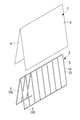
- a dust collector includes a casing having an inlet portion into which gas is introduced, a thorn-shaped discharge thorn and a mounting frame that supports the discharge thorn, and a voltage is applied thereto.
- a discharge electrode having a plate-like member, and a dust collecting electrode installed opposite to the discharge electrode in the casing, wherein the mounting frame is inclined with respect to the gas flow at the inlet portion.
- the two mounting frames are connected to each other on the downstream side of the gas flow, and are installed between the two mounting frames so that the upstream side of the gas flow is wider than the downstream side of the gas flow. ing.
- the particulate matter contained in the exhaust gas is ionized and ionized by corona discharge occurring at the discharge electrode.
- the particulate matter is collected by the dust collecting electrode.
- the mounting frames of the two discharge electrodes are connected to each other on the downstream side of the gas flow, and the upstream side of the gas flow is wider than the downstream side of the gas flow, the connecting portion between the mounting frames Is provided on the upper side, the discharge electrode can be self-supported only by support from the lower part, and support at the upper part is unnecessary.
- the connection portion between the attachment frames is provided below, the attachment frames are connected to each other and the cross-sectional shape is maintained, so that support at the lower portion is unnecessary.
- the discharge electrode is inclined with respect to the flow direction of the gas flow, and the upstream side of the gas flow is wide, so that an increase in the flow velocity at the gas inflow portion can be reduced and the occurrence of drift can be suppressed.
- the plate-like member of the dust collecting electrode is a member having conductivity, for example, having an opening such as a wire mesh or punching metal.
- the plate-like member is inclined with respect to the gas flow at the inlet, and the two dust collecting electrodes are connected to each other on the downstream side of the gas flow. It may be installed so that the upstream side of the flow is wider than the downstream side of the gas flow.
- the plate-like member of the dust collection electrode is inclined with respect to the gas flow at the inlet, the ionized particulate matter is collected regardless of the upstream and downstream sides of the gas flow. Hence pass through. Since the two dust collecting electrodes are connected to each other on the downstream side of the gas flow, and the upstream side of the gas flow is set wider than the downstream side of the gas flow, the structure for supporting the dust collecting electrode is reduced or Can be omitted.
- a plurality of water spray portions provided along the plate-like member of the dust collecting electrode and spraying water, and provided around the water spray portion along the plate-like member, the water spray And a flowing water plate that receives the water sprayed from the section and flows the water toward the plate-shaped member.
- the water sprayed from the plurality of water spraying portions hits the flowing water plate and diffuses, and then flows toward the plate-like member of the dust collecting electrode. Therefore, compared with the case where water is sprayed directly from the water spraying portion toward the plate-like member of the dust collecting electrode, it is possible to form a liquid film by uniformly flowing water on the surface of the plate-like member of the dust collecting electrode. This can prevent corrosion of the dust collecting electrode.
- the edge part by the side of the plate-shaped member in a flat plate may be bent upward or downward. Thereby, water can be made to flow more uniformly toward the plate-like member of the dust collection electrode.
- the direction of the water sprayed from a water spraying part is an upper direction, the downward direction, or a horizontal direction, and the number of rows of the holes provided in the water spraying unit is one row or a plurality of rows.
- the said invention WHEREIN You may further provide the filter material installed in the surface opposite to the surface in which the said discharge electrode was provided with respect to the said dust collection electrode. According to this configuration, the overall collection efficiency can be improved by further providing the filter material.
- an electric field forming electrode is further provided on the surface opposite to the surface on which the dust collecting electrode is provided with respect to the filter material, the electrode being formed away from the filter material and applied with a voltage. Also good. According to this configuration, by further providing the electric field forming electrode, an electric field is formed in the filter material, and the charged particulate matter is collected by the electrostatic force, thereby improving the overall collection efficiency. it can.
- the discharge electrode may be installed on both sides of the dust collection electrode. According to this configuration, since the discharge space is formed on both sides of the dust collecting electrode, the collection efficiency can be improved.
- the above-described dust collection device is installed in a plurality of stages in series along the gas flow. According to this configuration, since a plurality of stages of dust collectors are installed in series along the gas flow, the collection efficiency can be improved.
- the dust collector according to the present invention includes a discharge electrode to which a voltage is applied, a plate-like member formed by a metal mesh, a dust collection electrode that is installed to face the discharge electrode, and the dust collection electrode.
- a plurality of water spraying portions provided along the plate-like member for spraying water, and provided around the water spraying portion along the plate-like member and receiving the water sprayed from the water spraying portion. And a water flow plate for flowing the water toward the plate member.
- a dust collection method includes a casing having an inlet portion into which gas is introduced, a thorn-shaped discharge thorn and a mounting frame that supports the discharge thorn and is applied with a voltage.
- a discharge electrode having a plate-like member, and a dust collecting electrode installed opposite to the discharge electrode in the casing, wherein the mounting frame is inclined with respect to the gas flow at the inlet portion.
- the two mounting frames support the load on the downstream side of the gas flow, and are installed so that the upstream side of the gas flow is wider than the downstream side of the gas flow between the two mounting frames. Particulate matter is collected using a dust collector.
- the capacity of the entire apparatus can be made compact and the collection efficiency can be increased.
- the dust collector 1 is installed in an exhaust gas treatment facility provided in a flue on the downstream side of an industrial combustion facility such as a coal-fired or heavy oil-fired power plant or an incinerator, for example.
- an industrial combustion facility such as a coal-fired or heavy oil-fired power plant or an incinerator, for example.
- the dust collector 1 can be used not only for industrial combustion equipment but also for air purification equipment filters (for example, clean room air conditioning filters, virus removal filters, etc.).
- the dust collector 1 includes a discharge electrode 2 for charging the particulate matter, a dust collection electrode 3 disposed opposite to the discharge electrode 2 and the like in order to remove particulate matter such as dust and mist.
- the discharge electrode 2 and the dust collection electrode 3 are installed in the casing 4.
- the discharge electrode 2 has a mounting frame 5 and a discharge barb 18.
- the discharge thorn 18 is installed in the mounting frame 5 and is installed in a thorn shape from the mounting frame 5 toward the dust collecting electrode 3.
- the mounting frame 5 is a linear member and is inclined with respect to the gas flow at the inlet.
- the upstream part of the gas flow of the dust collector 1 is located below the gravitational direction, and the downstream side of the gas flow is located above the gravitational direction.
- the mounting frame 5 is self-supporting on the electrode support member 14 by combining the two mounting frames 5A and 5B. That is, the two mounting frames 5A and 5B support the load on the downstream side of the gas flow, and are installed so that the upstream side of the gas flow is wider than the downstream side of the gas flow.
- the two mounting frames 5A and 5B are installed with an increased interval on the upstream side of the gas flow so that the superficial velocity is 1 m / s to 4 m / s.
- the shape in which a plurality of mounting frames 5A and 5B are combined is a triangular prism, the bottom surface is an upstream side of the gas flow, and the mounting frames 5A and 5B are formed on the side surfaces.
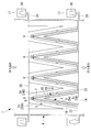
- the dust collection electrode 3 has a plate-like member 6 formed of a wire mesh or the like, and is installed facing the discharge electrode 2.
- the plate-like member 6 of the dust collecting electrode 3 is a conductive member in which an opening is formed, and is, for example, a wire mesh, a punching metal, or the like.
- the plate-like member 6 is inclined with respect to the gas flow at the inlet.
- the dust collecting electrode 3 is self-supporting on the electrode support member 14 by combining two plate-like members 6.
- the two plate-like members 6 support the load on the downstream side of the gas flow, and are installed so that the upstream side of the gas flow is wider than the downstream side of the gas flow.
- the dust collection electrode 3 is located above the discharge electrode 2 and is installed so as to cover the discharge electrode 2. However, the discharge electrode 2 and the dust collection electrode 3 are separated from each other and are electrically insulated.
- the electrode support member 14 penetrates the casing 4 and is connected to the insulator 16 accommodated in the insulator chamber 17.
- the electrode support 14 is covered with, for example, a cylindrical member 20 outside the casing 4 so that the gas flowing in the casing 4 does not leak, and the end of the cylindrical member 20 is blocked by the insulator chamber 17. It is.
- the discharge electrode 2 is connected to a high voltage power source (not shown) through an insulator 16 fixed to the casing 4 and an electrode support member 14. By applying the discharge electrode 2, corona discharge occurs at the discharge electrode 2. The particulate matter contained in the exhaust gas is ionized by corona discharge. The ionized particulate matter is collected by the dust collection electrode 3.
- the dust collector 1 shows an example in which the filter material 7 is provided in the dust collector 1, but the filter material 7 may not be installed and only the dust collection electrode 3 may be installed.
- the dust collector 1 desirably further includes a filter material 7 installed on the surface of the dust collecting electrode 3 opposite to the surface on which the discharge electrode 2 is provided.
- the filter material 7 is, for example, a medium performance filter. By further providing the filter material 7, the collection efficiency of the entire dust collector 1 can be improved.
- the filter material 7 preferably has finer specifications than the wire mesh.
- the material of the filter material 7 is not particularly limited.
- the corona discharge is generated in the discharge electrode 2, whereby the particulate matter contained in the exhaust gas is ionized,
- the ionized particulate matter is collected by the dust collection electrode 3.
- the mounting frame 5 of the two discharge electrodes 2 supports the load on the downstream side of the gas flow, and is installed so that the upstream side of the gas flow is wider than the downstream side of the gas flow. 2 can be self-supporting only by support from the bottom, and support at the top is unnecessary. Furthermore, since it is slanted with respect to the flow direction of the gas flow and the upstream side of the gas flow is wide, an increase in the flow velocity at the gas inflow portion can be reduced.
- the plate-like member 6 of the dust collecting electrode 3 is inclined with respect to the gas flow at the inlet portion, the ionized particulate form is used regardless of the upstream side and the downstream side of the gas flow.
- the substance surely passes through the dust collecting electrode 3.
- the two plate-like members 6 of the dust collecting electrode 3 support the load on the downstream side of the gas flow, and are installed so that the upstream side of the gas flow is wider than the downstream side of the gas flow.
- the shaped member 6 can be self-supporting only by support from the lower part, and support at the upper part is unnecessary. Furthermore, since it is slanted with respect to the flow direction of the gas flow and the upstream side of the gas flow is wide, an increase in the flow velocity at the gas inflow portion can be reduced.
- the upstream end of the gas flow of the dust collection electrode 3 is connected between the dust collection electrode 3 and the casing 4 or between the adjacent dust collection electrodes 3 by the plate-like member 22.
- the space between the dust collecting electrode 3 and the casing 4 or between the adjacent dust collecting electrodes 3 is blocked by the plate-like member 22, and the gas flow in the casing 4 is combined on the downstream side of the gas flow.
- the gas flows between the two plate-like members 6 and the gas can be prevented from flowing to other portions.
- the mounting frame 5 of the discharge electrode 2 and the shape of the longitudinal section of the plate-like member 6 of the dust collecting electrode 3 are triangular has been described, but the present invention is not limited to this example.
- the vertical cross-sectional shape of the mounting frame 5 of the discharge electrode 2 and the plate-like member 6 of the dust collecting electrode 3 may be a polygon other than a triangle (for example, a trapezoid, a pentagon, etc.).
- the modification of the dust collector 1 which concerns on this embodiment is demonstrated.
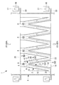
- the electric field forming electrode 24 is connected to the filter material 7 by the dust collection electrode 3. It is installed on the surface opposite to the surface provided with.
- the electric field forming electrode 24 is placed away from the filter material 7 and applied with a voltage.
- the power source for the electric field forming electrode 24 may be the same power source as that for the discharge electrode 2.
- the electric field forming electrode 24 is a linear member similar to the mounting frame 5 of the discharge electrode 2. Unlike the discharge electrode 2, the electric field forming electrode 24 is not provided with a thorn-shaped discharge thorn. The electric field forming electrode 24 faces the filter material 7 and is inclined with respect to the gas flow at the inlet. The electric field forming electrode 24 is suspended from the electrode support member 25 by combining the two frames 24A and 24B. That is, the two frames 24A and 24B are coupled to each other on the upstream side of the gas flow, and are coupled to the electrode support member 25 on the downstream side of the gas flow.
- the discharge electrode 2 when the filter material 7 is not installed, the discharge electrode 2 may be installed on both upper and lower surfaces of the dust collection electrode 3.
- the discharge electrode 2 installed above the dust collection electrode 3 also has the attachment frame 5 and the discharge barb 18 like the discharge electrode 2 installed below.
- the discharge electrode 2 installed above is suspended from the electrode support member 26 by combining two mounting frames 5C and 5D. That is, the two mounting frames 5C and 5D are coupled to each other on the upstream side of the gas flow. Since the discharge electrode 2 is installed on both sides of the dust collecting electrode 3, discharge spaces are formed on both sides of the dust collecting electrode 3, so that the collection efficiency can be improved.
- the dust collector 1 may be installed in only one stage in the exhaust gas treatment facility, or may be installed in a plurality of stages in series along the gas flow. In the dust collection system in which the dust collectors 1 are installed in a plurality of stages, since the plurality of stages of dust collectors 1 are installed in series along the gas flow, the collection efficiency can be improved.
- the dust collector 1 according to the present embodiment is not limited to the case where the configurations of the discharge electrode 2 and the dust collection electrode 3 have the shapes described above. That is, as shown in FIGS. 5 and 6, the discharge electrode 2 and the dust collection electrode 3 are not limited to the case where the discharge electrode 2 and the dust collection electrode 3 are oblique to the gas flow direction, and may be installed in parallel to the gas flow direction. Then, as shown in FIG. 5, the filter material 7 may be provided, and the electric field forming electrode 24 may be provided on the downstream side of the gas flow with respect to the dust collecting electrode 3, or as shown in FIG. The discharge electrode 2 may be installed on the downstream side of the gas flow with respect to the dust electrode 3.
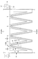
- the longitudinal direction of the mounting frame 5 and the plate-like member 6 may be installed in a direction parallel to the installation surface of the dust collector 1, that is, in the horizontal direction, and may be fixed to the electrode support member 14 in a cantilever manner. At this time, the gas flow in the casing 4 is a horizontal flow.
- the upstream portion of the gas flow of the dust collector 1 may be positioned above the gravity direction, and the downstream side of the gas flow may be positioned below the gravity direction.
- the mounting frame 5 is suspended from the electrode support member 27 by combining the two mounting frames 5A and 5B, and is installed so that the upstream side of the gas flow is wider than the downstream side of the gas flow. That is, since the two mounting frames 5A and 5B are connected to each other on the downstream side of the gas flow and the cross-sectional shape is maintained, support at the lower portion is not necessary. Further, the two plate-like members 6 of the dust collecting electrode 3 are also connected to each other on the downstream side of the gas flow, and need not be supported in the lower part.
- the present modified example further includes an example in which the above-described electric field forming electrode 24 is installed, and the dust collecting electrode 3 in which the filter material 7 is not installed. This is also applicable to an example in which only the discharge electrode 5 is installed on the back side of the dust collection electrode 3 without the filter material 7 being installed.
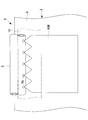
- the water cleaning unit 8 of the dust collector 1 is provided along the plate-like member 6 of the dust collecting electrode 3, and includes a water spraying unit 9 having a plurality of holes 9 a for spraying water downward, and a plate And a flat plate 10 that is provided in the lower portion of the water spraying portion 9 along the shaped member 6, receives water sprayed from the water spraying portion 9, and flows water toward the plate-like member 6.
- the water spraying part 9 is a tubular member, for example, and is installed on the upper part of the plate-like member 6.
- a plurality of holes 9a are formed in the tube wall of the water spray section 9 along the tube axis direction. Water is sprayed downward through the holes 9a.
- the water sprayed downward from the plurality of holes 9a of the water spray unit 9 strikes the flat plate 10 and diffuses, and then travels toward the plate-like member 6 of the dust collecting electrode 3. Flowing. Therefore, compared with the case where water is sprayed directly from the water spraying portion 9 toward the plate-like member 6 of the dust collecting electrode 3, the water film is made to flow uniformly on the surface of the plate-like member 6 of the dust collecting electrode 3. And the dust collecting electrode 3 can be washed uniformly.
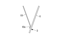
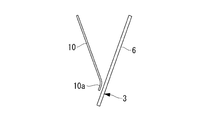
- the end portion 10a on the plate member 6 side of the flat plate 10 may have a straight section as shown in FIG. 8 or FIG. 10A, or on the plate member 6 side as shown in FIGS. 10B to 10D.
- the end 10a may be bent downward or upward.
- FIG. 10B and FIG. 10C are examples bent downward, and FIG. 10C is an example in which R is formed at the bent portion.
- FIG. 10D shows an example in which a dam is formed by bending upward. Thereby, water can flow more uniformly toward the plate-like member 6 of the dust collecting electrode 3.
- FIG. 8 the case where the water spraying portion 9 and the flat plate 10 are installed on the upper side of the plate-like member 6 on one side of the dust collecting electrode 3 has been described, but the present invention is not limited to this example.
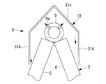
- one water spray section 9 may be installed in common on the upper part of the two plate-like members 6 of the dust collecting electrode 3.
- two flat plates 10 are installed in one water spray unit 9 corresponding to the two plate-like members 6.
- the holes 9a are formed in parallel to each other in at least two rows corresponding to both flat plates 10. Accordingly, as shown in FIGS. 3 and 4, when the electric field forming electrode 24 or the discharge electrode 2 is installed above the dust collection electrode 3, it is installed above the water spray portion 9 and the dust collection electrode 3. Further, the electric field forming electrode 24 or the discharge electrode 2 can be separated from each other, and discharge can be prevented from occurring between the water spray portion 9 and the electric field forming electrode 24 or the discharge electrode 2.
- the water flow board 31 is installed corresponding to the one water spraying part 9 installed in common on the upper part of the two plate-like members 6 of the dust collecting electrode 3.
- the flowing water plate 31 is provided above the water spray unit 9, and the upper portion is a semi-cylindrical 31 a and the lower portion is a flat plate 31 b parallel to each other.
- the water sprayed upward from the plurality of holes 9a of the water spraying part 9 hits the semi-cylinder 31a of the water flow plate 31, diffuses, and then flows through the two flat plates 31b to form a liquid film Is formed and flows toward the plate-like member 6 of the dust collecting electrode 3.
- a liquid film can be formed by flowing water uniformly over the surface of the plate-like member 6 of the dust collecting electrode 3, and the dust collecting electrode 3 can be washed uniformly. Further, the water spray portion 9 and the electric field forming electrode 24 or the discharge electrode 2 installed above the dust collecting electrode 3 can be separated, and the water spray portion 9 and the electric field forming electrode 24 or the discharge electrode 2 can be separated from each other. It is possible to prevent electric discharge from occurring.
- the water sprayer 9 may be provided with two rows of holes horizontally to spray water in the horizontal direction, or one row of holes may be provided at the top of the water sprayer 9 so that the water sprays only in one direction directly above. May be sprayed to form a liquid film.
- the flowing water plate 31 may have an upper portion formed of a bending plate 31c, and at this time, the flowing water plate 31 is installed so that the bending portion of the bending plate 31c is located at the apex portion.
- the two flat plates 31b of the water flow plate 31 do not need to be parallel to each other as long as the liquid film can be guided to the dust collecting electrode 3, and may be provided, for example, so as to spread outwardly. Further, processing such as bending the lower end portion of the flat plate 31b inward may be performed.
- cleaning part 8 is not restricted to the case where the structure of the discharge electrode 2 and the dust collection electrode 3 is the dust collector 1 which has the shape mentioned above. That is, as shown in FIGS. 5 and 6, the discharge electrode 2 and the dust collection electrode 3 are not limited to the case where the discharge electrode 2 and the dust collection electrode 3 are oblique to the gas flow direction, and may be installed in parallel to the gas flow direction.
- the water cleaning unit 8 is installed such that the lower ends of the two flat plates 31b of the water flow plate 31 are positioned at the upper ends of the two dust collecting electrodes 3 parallel to each other.
- the installation number of the water spraying parts 9 can be reduced.
- the water flow plate 31 can block the gas flow, and can flow the gas flowing from the upstream side toward the dust collecting electrode 3.
- the water cleaning unit 8 may be configured to clean the discharge electrode 2 by performing water spray from the upstream side in the gas flow direction.
- FIG. 1 when a plurality of rows of dust collection electrodes 2 and discharge electrodes 3 are provided, water cleaning is performed, for example, every two rows.
- FIG. 1 the example in which the water washing
- the water cleaning units 8A and 8B and the water cleaning unit 11A are started to be cleaned at the same time, and the other cleaning units 8 and 11 are stopped.
- the cleaning by the water cleaning unit 8A and the water cleaning unit 11A is stopped, and then the cleaning by the water cleaning units 8B and 8C and the water cleaning unit 11B is started. At this time, the other cleaning units 8 and 11 remain stopped.
- one water cleaning unit 11 is provided for two filter materials 7, but one water cleaning unit 11 is provided for one filter material 7. It may be installed one by one.
- the partition 4 etc. are not provided in the casing 4 of the dust collector 1 which concerns on embodiment mentioned above, this invention is not limited to this example.
- the dust collector 1 may be provided with a plurality of ducts 13 separated by a partition for each row of the dust collection electrode 2 and the discharge electrode 3.
- a damper 12 that can be opened and closed is installed at the outlet of the duct 13. Then, the damper 12 is closed when the dust collection electrode 2 and the discharge electrode 3 are cleaned.
- the damper 12 is closed, the gas does not pass through the dust collecting electrode 2 in the closed damper 12, so that the gas is surely against the surface of the plate-like member 6 of the dust collecting electrode 2 in the closed damper 12.
- a liquid film can be formed.
Landscapes
- Electrostatic Separation (AREA)
Abstract
Description
特許文献1では、粒子状物質を確実に捕集するため、イオン風によってケーシング中のガス流れを横切る方向へ粒子状物質を加速し、イオン風が通過可能な所定の開口率を有する集塵電極で粒子状物質を捕集する技術が開示されている。
二つの集塵電極が、ガス流れの下流側で互いに接続され、ガス流れの上流側がガス流れの下流側に比べ広くなるように設置されていることから、集塵電極を支持する構造を低減又は省略できる。
なお、平板における板状部材側の端部は、上方又は下方に曲げ加工されていてもよい。これにより、集塵電極の板状部材に向かって、水をより均一に流すことができる。また、水噴霧部から噴霧される水の方向は、上方、下方又は水平方向であり、水噴霧部に設けられる孔の列数は、1列又は複数列である。
この構成によれば、フィルタ材が更に設けられることで、全体の捕集効率を向上させることができる。
この構成によれば、電界形成用電極がさらに設けられることで、フィルタ材内に電場が形成され、静電気力によって、帯電した粒子状物質が捕集され、全体の捕集効率を向上させることができる。
この構成によれば、集塵電極の両面側に放電空間が形成されるため、捕集効率を向上させることができる。
この構成によれば、ガス流れに沿って直列に複数段の集塵装置が設置されるため、捕集効率を向上させることができる。
本実施形態に係る集塵装置1は、例えば、石炭焚きや重油焚きの発電プラントや焼却炉等の産業用燃焼設備の下流側の煙道内に設けられる排ガス処理設備に設置される。また、集塵装置1は、産業用燃焼設備以外に、空気浄化設備用フィルタ(例えば、クリーンルーム用空調フィルタ、ウィルス除去用フィルタ等)等にも使用できる。
取付枠5は、線状部材であり、入口部のガス流れに対して傾斜している。ここで、集塵装置1のガス流れの上流部が重力方向下方に位置し、ガス流れの下流側が重力方向上方に位置する。取付枠5は、二つの取付枠5A,5Bを組み合わせて電極支持材14上に自立している。すなわち、二つの取付枠5A,5Bが、ガス流れの下流側で互いに荷重を支持し、ガス流れの上流側がガス流れの下流側に比べ広くなるように設置されている。例えば、二つの取付枠5A,5Bは、空塔速度が1m/s~4m/sとなるように、ガス流れ上流側の間隔を広げて設置される。図1及び図2に示す例では、複数の取付枠5A,5Bを組み合わせて配置した形状が三角柱であり、底面部がガス流れの上流側であって開口し、側面に取付枠5A,5Bが設けられる。
集塵電極3は、板状部材6が入口部のガス流れに対して傾斜している。集塵電極3は、2枚の板状部材6を組み合わせて電極支持材14上に自立している。2枚の板状部材6が、ガス流れの下流側で互いに荷重を支持し、ガス流れの上流側がガス流れの下流側に比べ広くなるように設置されている。
集塵電極3は、放電電極2の上方に位置して、放電電極2を覆うように設置されているが、放電電極2と集塵電極3は互いに離隔され、電気的に絶縁されている。
集塵電極3の2枚の板状部材6が、ガス流れの下流側で互いに荷重を支持し、ガス流れの上流側がガス流れの下流側に比べ広くなるように設置されていることから、板状部材6は下部からの支持のみで自立可能であり、上部における支持が不要である。さらに、ガス流れの流れ方向に対して斜めであり、ガス流れの上流側が広いので、ガス流入部における流速の上昇を低減することができる。
上記実施形態では、フィルタ材7のガス流れ下流側に、他の電極等が設置されない例について説明したが、本変形例では、電界形成用電極24が、フィルタ材7に対して集塵電極3が設けられた面とは反対の面側に設置される。電界形成用電極24は、フィルタ材7から離隔して設置され、電圧が印加される。なお、電界形成用電極24の電源は、放電電極2と同一の電源を使用してもよい。
次に、図8~図13を参照して、本発明の一実施形態に係る集塵装置1の水洗浄部8について説明する。
水洗浄部8は、図8及び図9に示すように、集塵電極3の板状部材6に沿って設けられ、水を下方に噴霧する複数の孔9aを有する水噴霧部9と、板状部材6に沿って水噴霧部9の下部に設けられ、水噴霧部9から噴霧された水を受けて、板状部材6に向けて水を流す平板10とを更に備える。
また、流水板31は、図13に示すように、上部が曲げ板31cで形成されてもよく、このとき、頂点部分に曲げ板31cの屈曲部分が位置するように設置される。
さらに、流水板31の2枚の平板31bは、集塵電極3に液膜を導くことができれば互いに平行である必要はなく、例えば末広がりに設けてもよい。また、平板31bの下端部を内側へ折り曲げる等の加工をしてもよい。
図1に示すように集塵電極2及び放電電極3が複数列設けられる場合、水洗浄は、例えば2列ごとに行う。なお、図1では、フィルタ材7を洗浄するための水洗浄部11が更に設けられた例を示している。例えば、水洗浄部8A,8Bと水洗浄部11Aを同時に洗浄開始し、他は洗浄の洗浄部8,11を停止しておく。そして、水洗浄部8Aと水洗浄部11Aによる洗浄を停止し、次に、水洗浄部8B,8Cと水洗浄部11Bによる洗浄を開始する。このとき、他の洗浄部8,11は、停止したままである。その後、水洗浄部8Bと水洗浄部11Bによる洗浄を停止し、次に、水洗浄部8C,8Dと水洗浄部11Cを同時に洗浄開始する。この動作を繰り返し行うことで、集塵装置1全体の運転を停止する必要がない。また、水洗浄を全箇所で同時に行う場合に比べて集塵装置1の圧力損失を低減できる。
なお、水洗浄部11は、図1では、2枚のフィルタ材7に対して一つ設けられる場合について図示しているが、水洗浄部11は、1枚のフィルタ材7に対して一つずつ設置されてもよい。
2 放電電極
3 集塵電極
4 ケーシング
5 取付枠
6 板状部材
7 フィルタ材
8 水洗浄部
9 水噴霧部
10 平板(流水板)
14 電極支持材
16 碍子
18 放電トゲ
Claims (9)
- ガスが導入される入口部を有するケーシングと、
前記ケーシング内に設置され、トゲ状の放電トゲ及び前記放電トゲを支持する取付枠を有し、電圧が印加される放電電極と、
板状部材を有し、前記ケーシング内において前記放電電極に対向して設置される集塵電極と、
を備え、
前記取付枠は、前記入口部のガス流れに対して傾斜しており、
二つの前記取付枠が、前記ガス流れの下流側で互いに接続され、二つの前記取付枠の間において、前記ガス流れの上流側が前記ガス流れの下流側に比べ広くなるように設置されている集塵装置。 - 前記集塵電極は、前記板状部材が前記入口部のガス流れに対して傾斜しており、
二つの前記集塵電極が、前記ガス流れの下流側で互いに接続され、前記ガス流れの上流側が前記ガス流れの下流側に比べ広くなるように設置されている請求項1に記載の集塵装置。 - 前記集塵電極の前記板状部材に沿って設けられ、水を噴霧する複数の水噴霧部と、
前記板状部材に沿って前記水噴霧部の周囲に設けられ、前記水噴霧部から噴霧された前記水を受けて、前記板状部材に向けて前記水を流す流水板と、
を更に備える請求項1又は2に記載の集塵装置。 - 前記集塵電極に対して前記放電電極が設けられた面とは反対の面側に設置されたフィルタ材を更に備える請求項1から3のいずれか1項に記載の集塵装置。
- 前記フィルタ材に対して前記集塵電極が設けられた面とは反対の面側に、前記フィルタ材から離隔して設置され、電圧が印加される電界形成用電極を更に備える請求項4に記載の集塵装置。
- 前記放電電極が前記集塵電極の両面側に設置される請求項1から3のいずれか1項に記載の集塵装置。
- 請求項1から6のいずれか1項に記載の集塵装置がガス流れに沿って直列に複数段設置される集塵システム。
- 電圧が印加される放電電極と、
金網によって形成された板状部材を有し、前記放電電極に対向して設置される集塵電極と、
前記集塵電極の前記板状部材に沿って設けられ、水を噴霧する複数の水噴霧部と、
前記板状部材に沿って前記水噴霧部の周囲に設けられ、前記水噴霧部から噴霧された前記水を受けて、前記板状部材に向けて前記水を流す流水板と、
を備える集塵装置。 - ガスが導入される入口部を有するケーシングと、前記ケーシング内に設置され、トゲ状の放電トゲ及び前記放電トゲを支持する取付枠を有し電圧が印加される放電電極と、板状部材を有し前記ケーシング内において前記放電電極に対向して設置される集塵電極とを備え、前記取付枠は、前記入口部のガス流れに対して傾斜しており、二つの前記取付枠が、前記ガス流れの下流側で互いに接続され、二つの前記取付枠の間において、前記ガス流れの上流側が前記ガス流れの下流側に比べ広くなるように設置されている集塵装置を用いて、粒子状物質を捕集する集塵方法。
Priority Applications (5)
| Application Number | Priority Date | Filing Date | Title |
|---|---|---|---|
| JP2014560807A JP6367123B2 (ja) | 2013-02-07 | 2014-02-06 | 集塵装置、集塵システム及び集塵方法 |
| US14/765,753 US10071384B2 (en) | 2013-02-07 | 2014-02-06 | Dust collector, dust collection system, and dust collection method |
| CN201480007544.9A CN104994960B (zh) | 2013-02-07 | 2014-02-06 | 集尘器、集尘系统,及集尘方法 |
| BR112015018756-0A BR112015018756B1 (pt) | 2013-02-07 | 2014-02-06 | Coletor de poeira, sistema de coleta de poeira, e método de coleta de poeira |
| EP14749331.6A EP2954955B1 (en) | 2013-02-07 | 2014-02-06 | Dust collection apparatus, dust collection system, and dust collection method |
Applications Claiming Priority (2)
| Application Number | Priority Date | Filing Date | Title |
|---|---|---|---|
| JP2013052932 | 2013-02-07 | ||
| JPPCT/JP2013/052932 | 2013-02-07 |
Publications (1)
| Publication Number | Publication Date |
|---|---|
| WO2014123202A1 true WO2014123202A1 (ja) | 2014-08-14 |
Family
ID=51299793
Family Applications (1)
| Application Number | Title | Priority Date | Filing Date |
|---|---|---|---|
| PCT/JP2014/052802 WO2014123202A1 (ja) | 2013-02-07 | 2014-02-06 | 集塵装置、集塵システム及び集塵方法 |
Country Status (6)
| Country | Link |
|---|---|
| US (1) | US10071384B2 (ja) |
| EP (1) | EP2954955B1 (ja) |
| JP (1) | JP6367123B2 (ja) |
| CN (1) | CN104994960B (ja) |
| BR (1) | BR112015018756B1 (ja) |
| WO (1) | WO2014123202A1 (ja) |
Cited By (4)
| Publication number | Priority date | Publication date | Assignee | Title |
|---|---|---|---|---|
| JP2016159205A (ja) * | 2015-02-27 | 2016-09-05 | 三菱日立パワーシステムズ環境ソリューション株式会社 | So3除去装置及び排ガス処理システム、並びに、so3除去方法 |
| WO2017078614A1 (en) * | 2015-11-04 | 2017-05-11 | Blue Sky Engineering & Trading Pte Ltd | An electrostatic precipitator |
| JP2018126713A (ja) * | 2017-02-10 | 2018-08-16 | 三菱日立パワーシステムズ環境ソリューション株式会社 | 電気集塵装置 |
| WO2020026370A1 (ja) * | 2018-08-01 | 2020-02-06 | 三菱日立パワーシステムズ環境ソリューション株式会社 | 電気集塵装置 |
Families Citing this family (13)
| Publication number | Priority date | Publication date | Assignee | Title |
|---|---|---|---|---|
| US9827573B2 (en) * | 2014-09-11 | 2017-11-28 | University Of Washington | Electrostatic precipitator |
| US10668422B2 (en) * | 2015-10-30 | 2020-06-02 | Lg Electronics Inc. | Air freshener |
| EP3165842B1 (en) * | 2015-10-30 | 2020-10-07 | LG Electronics Inc. | Air freshener |
| CN106269256A (zh) * | 2016-08-10 | 2017-01-04 | 福建龙净环保股份有限公司 | 一种用于烟气净化的电除雾器 |
| CN107477641A (zh) * | 2017-09-19 | 2017-12-15 | 东北师范大学 | 基于物联网的楼宇排烟伞式静电净化处理系统 |
| JP7109194B2 (ja) * | 2018-01-15 | 2022-07-29 | 三菱重工パワー環境ソリューション株式会社 | 電気集塵装置 |
| CN108548697B (zh) * | 2018-05-07 | 2024-01-02 | 中国林业科学研究院 | 降尘收集器 |
| US11471816B2 (en) | 2019-03-11 | 2022-10-18 | Karim Salehpoor | Pollutant capturer and mobilizer |
| DE102019108207A1 (de) * | 2019-03-29 | 2020-10-01 | Bayerische Motoren Werke Aktiengesellschaft | Luftfiltervorrichtung für ein Kraftfahrzeug und Kraftfahrzeug mit einer solchen |
| CN111947239B (zh) * | 2019-05-14 | 2022-06-21 | 斗山重工业建设有限公司 | 空调系统用集尘装置及包含该集尘装置的空调装置 |
| EP4007658A1 (en) * | 2019-08-01 | 2022-06-08 | Infinite Cooling Inc. | Systems and methods for collecting fluid from a gas stream |
| EP4007657A1 (en) | 2019-08-01 | 2022-06-08 | Infinite Cooling Inc. | Panels for use in collecting fluid from a gas stream |
| WO2021173178A1 (en) | 2020-02-27 | 2021-09-02 | Infinite Cooling Inc. | Systems, devices, and methods for collecting species from a gas stream |
Citations (6)
| Publication number | Priority date | Publication date | Assignee | Title |
|---|---|---|---|---|
| GB1306388A (ja) * | 1970-05-12 | 1973-02-07 | ||
| JPS553885A (en) * | 1978-10-16 | 1980-01-11 | Ishikawajima Harima Heavy Ind Co Ltd | Particle trapping device |
| JPH07501745A (ja) * | 1991-12-11 | 1995-02-23 | ヤマモト,ユージロー | ガス状流動体の微粒子材料用フィルタ並びに方法 |
| JPH09141126A (ja) * | 1995-11-20 | 1997-06-03 | Mitsubishi Heavy Ind Ltd | ダクト型湿式電気集塵装置 |
| JP2007117968A (ja) | 2005-10-31 | 2007-05-17 | Mitsubishi Heavy Ind Ltd | ガス浄化装置及び方法 |
| JP2009131795A (ja) * | 2007-11-30 | 2009-06-18 | Daikin Ind Ltd | 湿式電気集塵機 |
Family Cites Families (26)
| Publication number | Priority date | Publication date | Assignee | Title |
|---|---|---|---|---|
| US2700429A (en) * | 1952-10-15 | 1955-01-25 | Research Corp | Electrical precipitator |
| JPS47770U (ja) | 1971-01-12 | 1972-08-05 | ||
| US4126434A (en) * | 1975-09-13 | 1978-11-21 | Hara Keiichi | Electrostatic dust precipitators |
| JPS5310179A (en) | 1976-07-14 | 1978-01-30 | Nippon Earo Piyuuru Kk | Wet wall forming method |
| JPS5925625B2 (ja) | 1978-07-21 | 1984-06-19 | 石川島播磨重工業株式会社 | 水膜式電気集じん機の水膜形成装置 |
| JPS58107151U (ja) | 1981-12-29 | 1983-07-21 | 中部電力株式会社 | 水膜式電気集じん装置の給水装置 |
| US4521229A (en) * | 1983-11-01 | 1985-06-04 | Combustion Engineering, Inc. | Tubular discharge electrode for electrostatic precipitator |
| JPS6115750A (ja) | 1984-06-30 | 1986-01-23 | Corona Giken Kogyo Kk | 排ガス浄化装置 |
| JPH0711102B2 (ja) * | 1986-11-05 | 1995-02-08 | 津田駒工業株式会社 | 空気噴射式織機の補助ノズル |
| SE463077B (sv) * | 1988-06-03 | 1990-10-08 | Boliden Contech Ab | Emissionselektrod |
| JP2902058B2 (ja) | 1990-06-21 | 1999-06-07 | 三菱重工業株式会社 | ミストエリミネータ |
| JPH054056A (ja) * | 1990-11-30 | 1993-01-14 | Toshiba Corp | 電気集塵機 |
| US5403383A (en) * | 1992-08-26 | 1995-04-04 | Jaisinghani; Rajan | Safe ionizing field electrically enhanced filter and process for safely ionizing a field of an electrically enhanced filter |
| CN2189003Y (zh) * | 1993-12-07 | 1995-02-08 | 周永贵 | 电收尘不锈钢极网 |
| JPH07265730A (ja) | 1994-03-29 | 1995-10-17 | Nippon Kayaku Co Ltd | 空気清浄脱臭装置 |
| US5549735C1 (en) | 1994-06-09 | 2001-08-14 | Coppom Technologies | Electrostatic fibrous filter |
| JPH10244832A (ja) | 1997-03-03 | 1998-09-14 | Advance Innov:Kk | 車両用サンバイザー |
| US6497754B2 (en) * | 2001-04-04 | 2002-12-24 | Constantinos J. Joannou | Self ionizing pleated air filter system |
| JP2002361117A (ja) | 2001-06-09 | 2002-12-17 | Ayumi Iijima | 電気集塵装置 |
| JP3973859B2 (ja) * | 2001-06-29 | 2007-09-12 | 松下エコシステムズ株式会社 | 電気集塵ユニット |
| JP2004167453A (ja) | 2002-11-22 | 2004-06-17 | Mitsubishi Heavy Ind Ltd | 除塵装置 |
| US6790259B2 (en) | 2003-01-16 | 2004-09-14 | Blueair Ab | Method and device for cleaning a gaseous fluid using a conductive grid between charging head and filter |
| JP4339049B2 (ja) * | 2003-08-29 | 2009-10-07 | 日新電機株式会社 | 排ガス処理方法及び排ガス処理装置 |
| JP2008212846A (ja) | 2007-03-05 | 2008-09-18 | Hitachi Plant Technologies Ltd | 湿式電気集塵装置の流水機構 |
| CN101396677B (zh) | 2008-11-05 | 2011-12-21 | 中冶京诚工程技术有限公司 | 极板冲洗装置及方法 |
| US8889079B2 (en) * | 2010-01-13 | 2014-11-18 | Efb, Inc. | Apparatus for removal of particles and VOC from an airstream |
-
2014
- 2014-02-06 US US14/765,753 patent/US10071384B2/en active Active
- 2014-02-06 EP EP14749331.6A patent/EP2954955B1/en active Active
- 2014-02-06 JP JP2014560807A patent/JP6367123B2/ja active Active
- 2014-02-06 BR BR112015018756-0A patent/BR112015018756B1/pt active IP Right Grant
- 2014-02-06 WO PCT/JP2014/052802 patent/WO2014123202A1/ja active Application Filing
- 2014-02-06 CN CN201480007544.9A patent/CN104994960B/zh active Active
Patent Citations (6)
| Publication number | Priority date | Publication date | Assignee | Title |
|---|---|---|---|---|
| GB1306388A (ja) * | 1970-05-12 | 1973-02-07 | ||
| JPS553885A (en) * | 1978-10-16 | 1980-01-11 | Ishikawajima Harima Heavy Ind Co Ltd | Particle trapping device |
| JPH07501745A (ja) * | 1991-12-11 | 1995-02-23 | ヤマモト,ユージロー | ガス状流動体の微粒子材料用フィルタ並びに方法 |
| JPH09141126A (ja) * | 1995-11-20 | 1997-06-03 | Mitsubishi Heavy Ind Ltd | ダクト型湿式電気集塵装置 |
| JP2007117968A (ja) | 2005-10-31 | 2007-05-17 | Mitsubishi Heavy Ind Ltd | ガス浄化装置及び方法 |
| JP2009131795A (ja) * | 2007-11-30 | 2009-06-18 | Daikin Ind Ltd | 湿式電気集塵機 |
Non-Patent Citations (1)
| Title |
|---|
| See also references of EP2954955A4 |
Cited By (4)
| Publication number | Priority date | Publication date | Assignee | Title |
|---|---|---|---|---|
| JP2016159205A (ja) * | 2015-02-27 | 2016-09-05 | 三菱日立パワーシステムズ環境ソリューション株式会社 | So3除去装置及び排ガス処理システム、並びに、so3除去方法 |
| WO2017078614A1 (en) * | 2015-11-04 | 2017-05-11 | Blue Sky Engineering & Trading Pte Ltd | An electrostatic precipitator |
| JP2018126713A (ja) * | 2017-02-10 | 2018-08-16 | 三菱日立パワーシステムズ環境ソリューション株式会社 | 電気集塵装置 |
| WO2020026370A1 (ja) * | 2018-08-01 | 2020-02-06 | 三菱日立パワーシステムズ環境ソリューション株式会社 | 電気集塵装置 |
Also Published As
| Publication number | Publication date |
|---|---|
| EP2954955A1 (en) | 2015-12-16 |
| JP6367123B2 (ja) | 2018-08-01 |
| CN104994960B (zh) | 2019-01-11 |
| BR112015018756B1 (pt) | 2022-01-25 |
| US20150375237A1 (en) | 2015-12-31 |
| JPWO2014123202A1 (ja) | 2017-02-02 |
| BR112015018756A2 (pt) | 2017-07-18 |
| EP2954955B1 (en) | 2022-07-13 |
| EP2954955A4 (en) | 2016-12-28 |
| CN104994960A (zh) | 2015-10-21 |
| US10071384B2 (en) | 2018-09-11 |
Similar Documents
| Publication | Publication Date | Title |
|---|---|---|
| JP6367123B2 (ja) | 集塵装置、集塵システム及び集塵方法 | |
| JP6104950B2 (ja) | 集塵装置、集塵装置の電極選定方法及び集塵方法 | |
| FI20165186A (en) | Air purifier and procedure for purification of room air | |
| KR102095316B1 (ko) | 세정장치를 구비한 2단 하전식 플라즈마 집진기 | |
| CN103313795A (zh) | 使用多交叉针离子产生器的感应式静电集尘器 | |
| TWI651122B (zh) | 一種用於煙氣淨化的電除霧器 | |
| CN106765416B (zh) | 油烟净化器 | |
| JP6333697B2 (ja) | 電気集じん装置 | |
| CN102784718B (zh) | 一种带雾帘的高压静电除尘器 | |
| JP6167326B2 (ja) | 塗装ミスト処理装置 | |
| CN106999951B (zh) | 湿式静电除尘器以及处理废气的方法 | |
| CN104190544A (zh) | 一种可拆卸式烟气湿式静电除尘除雾装置及应用 | |
| CN106237772B (zh) | 协同脱除多种污染物的湿式电袋复合除尘器 | |
| RU2281147C1 (ru) | Пылевая камера | |
| JP6390004B2 (ja) | 電気集塵装置 | |
| JP3235014B2 (ja) | 電気集塵装置 | |
| CN111940139A (zh) | 自生风空气净化器 | |
| JP6788881B2 (ja) | 空気浄化機 | |
| KR101072480B1 (ko) | 충돌식 습식 스크러버 | |
| CN214717515U (zh) | 一种油烟净化器内置高压静电除油装置 | |
| JP2001232239A (ja) | 電気集塵装置 | |
| KR100812716B1 (ko) | 가스 불순물 제거 장치 | |
| Seetharama et al. | Comparison of wet and dry electrostatic precipitator (ESP) technologies | |
| JP2016198699A (ja) | 集塵装置及びこれを備えるガス処理システム | |
| JP6220172B2 (ja) | 集塵装置 |
Legal Events
| Date | Code | Title | Description |
|---|---|---|---|
| 121 | Ep: the epo has been informed by wipo that ep was designated in this application |
Ref document number: 14749331 Country of ref document: EP Kind code of ref document: A1 |
|
| ENP | Entry into the national phase |
Ref document number: 2014560807 Country of ref document: JP Kind code of ref document: A |
|
| WWE | Wipo information: entry into national phase |
Ref document number: 14765753 Country of ref document: US Ref document number: 2014749331 Country of ref document: EP |
|
| WWE | Wipo information: entry into national phase |
Ref document number: IDP00201504801 Country of ref document: ID |
|
| NENP | Non-entry into the national phase |
Ref country code: DE |
|
| REG | Reference to national code |
Ref country code: BR Ref legal event code: B01A Ref document number: 112015018756 Country of ref document: BR |
|
| ENP | Entry into the national phase |
Ref document number: 112015018756 Country of ref document: BR Kind code of ref document: A2 Effective date: 20150805 |