WO2014119431A1 - 連続重合装置および重合体組成物の製造方法 - Google Patents
連続重合装置および重合体組成物の製造方法 Download PDFInfo
- Publication number
- WO2014119431A1 WO2014119431A1 PCT/JP2014/051158 JP2014051158W WO2014119431A1 WO 2014119431 A1 WO2014119431 A1 WO 2014119431A1 JP 2014051158 W JP2014051158 W JP 2014051158W WO 2014119431 A1 WO2014119431 A1 WO 2014119431A1
- Authority
- WO
- WIPO (PCT)
- Prior art keywords
- reactor
- temperature
- polymerization
- raw material
- material monomer
- Prior art date
Links
Images

Classifications
-
- C—CHEMISTRY; METALLURGY
- C08—ORGANIC MACROMOLECULAR COMPOUNDS; THEIR PREPARATION OR CHEMICAL WORKING-UP; COMPOSITIONS BASED THEREON
- C08F—MACROMOLECULAR COMPOUNDS OBTAINED BY REACTIONS ONLY INVOLVING CARBON-TO-CARBON UNSATURATED BONDS
- C08F2/00—Processes of polymerisation
- C08F2/01—Processes of polymerisation characterised by special features of the polymerisation apparatus used
-
- B—PERFORMING OPERATIONS; TRANSPORTING
- B01—PHYSICAL OR CHEMICAL PROCESSES OR APPARATUS IN GENERAL
- B01J—CHEMICAL OR PHYSICAL PROCESSES, e.g. CATALYSIS OR COLLOID CHEMISTRY; THEIR RELEVANT APPARATUS
- B01J19/00—Chemical, physical or physico-chemical processes in general; Their relevant apparatus
- B01J19/0006—Controlling or regulating processes
- B01J19/0013—Controlling the temperature of the process
-
- B—PERFORMING OPERATIONS; TRANSPORTING
- B01—PHYSICAL OR CHEMICAL PROCESSES OR APPARATUS IN GENERAL
- B01J—CHEMICAL OR PHYSICAL PROCESSES, e.g. CATALYSIS OR COLLOID CHEMISTRY; THEIR RELEVANT APPARATUS
- B01J19/00—Chemical, physical or physico-chemical processes in general; Their relevant apparatus
- B01J19/18—Stationary reactors having moving elements inside
- B01J19/1862—Stationary reactors having moving elements inside placed in series
-
- B—PERFORMING OPERATIONS; TRANSPORTING
- B01—PHYSICAL OR CHEMICAL PROCESSES OR APPARATUS IN GENERAL
- B01J—CHEMICAL OR PHYSICAL PROCESSES, e.g. CATALYSIS OR COLLOID CHEMISTRY; THEIR RELEVANT APPARATUS
- B01J19/00—Chemical, physical or physico-chemical processes in general; Their relevant apparatus
- B01J19/24—Stationary reactors without moving elements inside
- B01J19/245—Stationary reactors without moving elements inside placed in series
-
- C—CHEMISTRY; METALLURGY
- C08—ORGANIC MACROMOLECULAR COMPOUNDS; THEIR PREPARATION OR CHEMICAL WORKING-UP; COMPOSITIONS BASED THEREON
- C08F—MACROMOLECULAR COMPOUNDS OBTAINED BY REACTIONS ONLY INVOLVING CARBON-TO-CARBON UNSATURATED BONDS
- C08F2/00—Processes of polymerisation
- C08F2/001—Multistage polymerisation processes characterised by a change in reactor conditions without deactivating the intermediate polymer
-
- B—PERFORMING OPERATIONS; TRANSPORTING
- B01—PHYSICAL OR CHEMICAL PROCESSES OR APPARATUS IN GENERAL
- B01J—CHEMICAL OR PHYSICAL PROCESSES, e.g. CATALYSIS OR COLLOID CHEMISTRY; THEIR RELEVANT APPARATUS
- B01J2219/00—Chemical, physical or physico-chemical processes in general; Their relevant apparatus
- B01J2219/00049—Controlling or regulating processes
- B01J2219/00051—Controlling the temperature
- B01J2219/00054—Controlling or regulating the heat exchange system
- B01J2219/00056—Controlling or regulating the heat exchange system involving measured parameters
- B01J2219/00058—Temperature measurement
-
- B—PERFORMING OPERATIONS; TRANSPORTING
- B01—PHYSICAL OR CHEMICAL PROCESSES OR APPARATUS IN GENERAL
- B01J—CHEMICAL OR PHYSICAL PROCESSES, e.g. CATALYSIS OR COLLOID CHEMISTRY; THEIR RELEVANT APPARATUS
- B01J2219/00—Chemical, physical or physico-chemical processes in general; Their relevant apparatus
- B01J2219/00049—Controlling or regulating processes
- B01J2219/00051—Controlling the temperature
- B01J2219/00074—Controlling the temperature by indirect heating or cooling employing heat exchange fluids
- B01J2219/00087—Controlling the temperature by indirect heating or cooling employing heat exchange fluids with heat exchange elements outside the reactor
- B01J2219/00094—Jackets
-
- B—PERFORMING OPERATIONS; TRANSPORTING
- B01—PHYSICAL OR CHEMICAL PROCESSES OR APPARATUS IN GENERAL
- B01J—CHEMICAL OR PHYSICAL PROCESSES, e.g. CATALYSIS OR COLLOID CHEMISTRY; THEIR RELEVANT APPARATUS
- B01J2219/00—Chemical, physical or physico-chemical processes in general; Their relevant apparatus
- B01J2219/00049—Controlling or regulating processes
- B01J2219/00051—Controlling the temperature
- B01J2219/00074—Controlling the temperature by indirect heating or cooling employing heat exchange fluids
- B01J2219/00087—Controlling the temperature by indirect heating or cooling employing heat exchange fluids with heat exchange elements outside the reactor
- B01J2219/00103—Controlling the temperature by indirect heating or cooling employing heat exchange fluids with heat exchange elements outside the reactor in a heat exchanger separate from the reactor
-
- B—PERFORMING OPERATIONS; TRANSPORTING
- B01—PHYSICAL OR CHEMICAL PROCESSES OR APPARATUS IN GENERAL
- B01J—CHEMICAL OR PHYSICAL PROCESSES, e.g. CATALYSIS OR COLLOID CHEMISTRY; THEIR RELEVANT APPARATUS
- B01J2219/00—Chemical, physical or physico-chemical processes in general; Their relevant apparatus
- B01J2219/24—Stationary reactors without moving elements inside
Definitions
- the present invention relates to a continuous polymerization apparatus, that is, an apparatus for continuously performing polymerization.
- the present invention also relates to a method for producing a polymer composition carried out using such a continuous polymerization apparatus.
- a resin composition such as a methacrylic acid ester polymer is produced by continuous polymerization in which raw material monomers, a polymerization initiator, and the like are continuously supplied to a reactor and polymerized.
- a continuous polymerization method a continuous solution polymerization method in which continuous polymerization is performed using a solvent (or a dispersion medium, the same applies hereinafter) and a continuous bulk polymerization method in which continuous polymerization is performed without using a solvent are known.
- the continuous solution polymerization method is not efficient because it uses a solvent, and is not efficient.
- the continuous bulk polymerization method has an advantage that a polymer composition can be efficiently produced because a polymerization reaction is carried out without using a solvent.
- the continuous bulk polymerization method is difficult to control the reaction because the viscosity of the reaction mixture is high, and the inner surface of the reaction apparatus is used to remove heat from the reaction system. When cooled, there were various problems such as deterioration of the quality of the polymer composition and thus the resin composition obtained therefrom.
- Patent Documents 1 and 2 are not necessarily sufficient to meet such demands.
- An object of the present invention is to provide a novel continuous polymerization apparatus, and more efficiently a polymer composition that can be implemented using such a continuous polymerization apparatus and is suitable for obtaining a high-quality resin composition.
- An object of the present invention is to provide a method for producing a polymer composition that can be produced in an automated manner.
- the present inventors have examined the use of a combination of at least two reactors (preferably a complete mixing reactor) in order to carry out continuous polymerization.
- the reaction apparatus is composed of two stages, and most of the polymerization is performed in the former reaction apparatus, and the polymerization is completed in the latter reaction apparatus and the polymerization initiator is removed (Patent Document 3),
- An apparatus Patent Document 4 is known in which polymerization is performed to some extent in the former reaction apparatus and polymerization is performed by adding a solvent in the latter reaction apparatus.
- the heat removal of the reaction system is performed by reflux cooling (evaporation of raw material monomers in the reaction apparatus is taken out to the outside, this is cooled and condensed, and then returned to the reaction apparatus again).
- reflux cooling evaporation of raw material monomers in the reaction apparatus is taken out to the outside, this is cooled and condensed, and then returned to the reaction apparatus again.
- the viscosity of the mixture in the reaction system increases, and the reaction system tends to be locally or rapidly cooled.
- gel adhesion and growth on the inner wall surface of the resin become remarkable, and the gelled product is mixed as an impurity in the polymer composition obtained.
- the inventors of the present invention conducted the first reactor to continuously polymerize the raw material monomer in the presence of a polymerization initiator to form an intermediate composition.
- a high-quality resin composition, in particular methacrylic acid is supplied continuously into the second reactor, and a new raw material monomer is separately supplied to the second reactor to carry out a continuous polymerization reaction.
- the present inventors have found that an acid ester-based polymer can be produced efficiently and have completed the present invention.
- the present invention can provide the following [1] to [13].
- [1] Including at least first and second reactors; Each reaction device has at least one supply port, an extraction port, and temperature detection means for detecting the temperature in each reaction device,
- the supply port of the first reactor is connected to a supply source of raw material monomers and a polymerization initiator,
- the outlet of the first reactor is connected to the first supply port of the second reactor by a connection line,
- a continuous polymerization apparatus in which the second supply port of the second reaction apparatus is connected to a replenishment line for supplying new raw material monomers to the second reaction apparatus.
- each of the reaction apparatuses is a tank-type reaction apparatus, and an outlet port of each of the reaction apparatuses is located at the top of each reaction apparatus.
- each of the reaction apparatuses is a complete mixing type reaction apparatus.
- the first or second supply port of the second reaction apparatus or the third supply port provided in the second reaction apparatus is connected to a supply source of a new polymerization initiator.
- the continuous polymerization apparatus according to any one of [6].
- a second raw material monomer is supplied from the second reactor, and further subjected to continuous polymerization in the second reactor, and the resulting polymer composition is continuously extracted from the outlet of the second reactor.
- the flow rate ratio of the intermediate composition extracted from the outlet of the first reactor to the connection line and the new raw material monomer supplied from the replenishment line to the second reactor is 0.995: 0. 005 to 0.5:
- the temperature in the first reactor detected by the temperature detector of the first reactor and the temperature in the second reactor detected by the temperature detector of the second reactor are both The method for producing a polymer composition according to any one of [9] to [11] above, which is within the range of 120 to 150 ° C.
- a novel continuous polymerization apparatus is provided.
- a polymer composition suitable for obtaining a high-quality resin composition can be more efficiently obtained using such a continuous polymerization apparatus.
- a method for producing a polymer composition that can be produced easily.
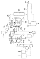
- FIG. 1 It is the schematic which shows the continuous polymerization apparatus in one embodiment of this invention.
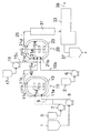
- FIG. 1 it is the schematic which shows the example of the continuous polymerization apparatus of this invention which provided the jacket in the connection line.
- FIG. 1 it is the schematic which shows the example of the continuous polymerization apparatus of this invention which provided the cooler in the connection line.
- the continuous polymerization apparatus of the present invention includes at least two reaction apparatuses, and continuous polymerization such as continuous bulk polymerization and continuous solution polymerization can be performed in each reaction apparatus.
- the continuous polymerization apparatus of the present invention is understood as a continuous bulk polymerization apparatus when continuous bulk polymerization is performed in all reactors, and a continuous solution polymerization apparatus when continuous solution polymerization is performed in all reaction apparatuses.
- the present invention is not limited thereto, and the continuous polymerization apparatus of the present invention is such that a continuous bulk polymerization is performed in a certain reaction apparatus (for example, at least one reaction apparatus in the preceding stage), and a certain reaction apparatus (for example, at least one in the subsequent stage). In the reactor), continuous solution polymerization may be carried out.
- the continuous polymerization apparatus of this embodiment includes at least a first reaction apparatus 10 and a second reaction apparatus 20.
- These reactors 10 and 20 are not particularly limited as long as continuous polymerization such as continuous bulk polymerization and continuous solution polymerization can be performed.
- the reactors 10 and 20 may be tank reactors or tube reactors, preferably (continuous ) Tank type reaction apparatus, more preferably a complete mixing type (continuous) tank type reaction apparatus. More preferably, each of the reactors 10 and 20 is a fully mixed type reactor, preferably a fully mixed (continuous) tank type reactor.
- continuous bulk polymerization is performed. It is particularly preferred to be used in Note that the reactors 10 and 20 used in this embodiment are not limited to completely mixed reactors used for carrying out continuous bulk polymerization.
- the reaction apparatus used in the present invention is not limited to a complete mixing type reaction apparatus.
- the first reaction apparatus 10 has at least a supply port 11a and an extraction port 11b, and preferably a jacket 13 as temperature adjusting means for adjusting the temperature of the outer wall surface of the reaction apparatus, You may further have the stirrer 14 for stirring the contents.
- the second reactor 20 has at least a first supply port 21a, a second supply port 21b, and an extraction port 21d, and preferably for adjusting the temperature of the outer wall surface of the reaction device. You may further have the jacket 23 surrounding the outer wall surface of a reactor as temperature control means, and the stirrer 24 for stirring the contents.
- the outlets 11b and 21d are preferably provided at the top of each reactor in the present embodiment, but are not limited thereto.
- the supply port 11a and the supply ports 21a and 21b do not limit the present embodiment, but can be generally provided at any appropriate position below each reactor.
- these reaction apparatuses 10 and 20 are each provided with temperature sensors (T 1 , T 2 ) as temperature detection means for detecting the temperature in each reaction apparatus.
- the position of the temperature sensor (T 1 , T 2 ) is not particularly limited as long as it can detect the temperature of the reaction mixture inside the reaction apparatus, but is preferably provided at the top of the reaction apparatus.
- the volumes of the first reactor 10 and the second reactor 20 may be the same or different. By making the volume of the first reactor 10 and the volume of the second reactor 20 different, the average residence time is effectively made different between the first reactor 10 and the second reactor 20. Can do.
- the agitators 14 and 24 are for bringing the inside of the reactor into a substantially completely mixed state.
- These agitators may be equipped with any appropriate agitating blade, such as a MIG wing, a Max blend wing (registered trademark, manufactured by Sumitomo Heavy Industries, Ltd.), a paddle wing, a double helical ribbon wing, a full zone. Wings (registered trademark, manufactured by Shinko Environmental Solution Co., Ltd.) may be provided.
- a baffle in the reactor.
- the present embodiment is not limited to this, and may have any appropriate configuration in place of the agitators 14 and 24 as long as the inside of the reactor can be mixed, preferably in a substantially complete mixing state.
- the stirring power is not particularly limited, but is preferably 0.5 to 30 kW / m 3 , more preferably 0.5 to 20 kW / m 3 , and even more preferably 1 to 15 kW / m 3. m is 3.
- the stirring power is preferably set larger as the viscosity of the reaction system becomes higher (or as the content of the polymer in the reaction system becomes higher).
- the supply port 11a of the first reactor 10 is pumped to a raw material monomer tank (raw material monomer supply source) 1 and a polymerization initiator tank (a polymerization initiator and optionally a raw material monomer supply source) 3 respectively.
- the raw material supply line 9 is connected through 5 and 7.
- the raw material monomer and the polymerization initiator supply source to the first reactor 10 are the raw material monomer tank 1 and the polymerization initiator tank 3, but the number of raw material monomer and polymerization initiator supply sources and The aspects of the raw material monomer and the polymerization initiator (for example, the composition in the case of a mixture) are not particularly limited as long as the raw material monomer and the polymerization initiator can be appropriately supplied to the first reactor 10.
- the first reactor 10 may be provided with another supply port 11c, and this supply port 11c is connected to the polymerization initiator tank 3 with a pump 7 as shown by a dotted line in FIG. It may be connected via.
- the supply from the polymerization initiator tank 3 to the supply port 11a may or may not be stopped.
- the outlet 11b of the first reactor 10 can be connected to the first supply port 21a of the second reactor 20 through the connection line 15a.
- the extraction port 21 d of the second reactor 20 is connected to the extraction line 25.
- a pump may or may not exist on the connection line 15a between the outlet 11b of the first reactor 10 and the first supply port 21a of the second reactor 20. However, it is preferred that no pump is present.
- connection line 15a is connected to the first supply port 21a of the second reaction apparatus 20 from the extraction port 11b of the first reaction apparatus 10, while separately adding a new raw material monomer (and possibly A replenishment line 15b capable of supplying other components such as a chain transfer agent) to the second reactor 20 is connected to a second supply port 21b provided at an arbitrary position of the second reactor 20. It is characterized by.
- the position of the second supply port 21b is not particularly limited. Even if it is below the first supply port 21a of the second reactor 20 or at the same height as the first supply port 21a, It may be above the first supply port 21a.
- a new raw material monomer is separately supplied into the second reaction apparatus 20 to be newly supplied to the second reaction apparatus 20. Since the conditions such as the temperature and supply amount of the raw material monomer can be controlled in detail separately, a polymer composition suitable for obtaining a high-quality resin composition can be produced more efficiently. In particular, by adjusting, preferably cooling, the temperature of the raw material monomer supplied to the second reactor 20, the polymerization reaction in the second reactor 20 can be desirably controlled at a low temperature. A polymer composition suitable for obtaining a high-quality resin composition, particularly a high-quality methacrylic acid ester-based polymer, can be produced more efficiently.
- the replenishment line 15b is for supplying a new raw material monomer separately to the second reactor 20, and a new raw material monomer tank (a raw material monomer and possibly other components such as a chain transfer agent).
- Source a raw material monomer and possibly other components such as a chain transfer agent.
- Source a raw material monomer and possibly other components such as a chain transfer agent.
- the source of the new raw material monomer (and possibly other components such as a chain transfer agent) to the second reactor 20 is the raw material monomer tank 2 provided separately.
- the number of the supply sources and the form of the raw material monomers are not particularly limited as long as new raw material monomers can be appropriately supplied from the replenishment line 15b to the second reactor 20.
- the raw material monomer contained in the raw material monomer tank (raw material monomer supply source) 2 is the same as or different from the raw material monomer contained in the raw material monomer tank (raw material monomer supply source) 1. Also good. With this configuration, a new raw material monomer can be supplied from the replenishment line 15b to the second reactor 20 in accordance with the temperature of the first reactor 10 and / or the second reactor 20 and the like.
- the first reaction apparatus 10 includes the temperature sensor T 1 as temperature detection means for detecting the temperature in the first reaction apparatus 10, and thus the second reaction apparatus 20 includes the second reaction apparatus 20.
- the temperature in the refill line 15b in the vicinity of the supply port 21b in particular the temperature of the raw material monomer fed to the second reactor 20, the temperature of the first reactor 10 detected by the temperature sensor T 1
- the temperature may be controlled to be lower (for example, a preset temperature range).
- the raw material monomer tank 2 and / or the replenishment line 15b may appropriately include temperature adjusting means such as a heating means, a cooling means, a heat retaining means, and a heat insulating means as necessary.
- the raw material monomer tank 2 and / or the replenishment line 15b is preferably provided with a cooling means as a temperature adjusting means, and the raw material monomer (and other components such as a chain transfer agent depending on the case) is preferably -40 to 30 ° C., preferably Is preferably cooled to a temperature of ⁇ 40 to 10 ° C., and the raw material monomer is preferably supplied into the second reactor 20 from the second supply port 21 b of the second reactor 20.
- the polymerization reaction in the second reactor 20 can proceed at a low temperature, and the syndiotacticity of the formed polymer (polymer) is increased.
- the heat resistance of the resulting polymer composition is improved.
- the second reactor 20 by separately cooling the raw material monomer and supplying it into the second reactor 20 in this way, in the second reactor 20, the formation of by-products is suppressed, and the resulting polymer composition The purity and degree of polymerization are improved, and the thermal stability and heat resistance are improved.
- the second reactor 20 is preferably connected to a polymerization initiator tank (a new polymerization initiator and, optionally, a source of raw material monomers) 17 via a pump 19.
- the supply source of the new polymerization initiator is the polymerization initiator tank 17, but the number of supply sources of the new polymerization initiator and the mode of the polymerization initiator (for example, the composition in the case of a mixture) These are not particularly limited as long as a new polymerization initiator can be appropriately supplied to the second reactor 20.
- the first supply port 21a of the second reactor 20 is connected to the polymerization initiator tank 17 via the pump 19 as shown in FIG.
- the second reactor 20 may be provided with a third supply port 21c, and this third supply port 21c is shown by a dotted line in FIG. 1, for example.
- the polymerization initiator tank 17 may be connected via a pump 19. At this time, the supply from the polymerization initiator tank 17 to the connection line 15a (and the first supply port 21a) may be stopped or may not be stopped. Further, as indicated by a dotted line in FIG. 1, the polymerization initiator tank 17 may be connected at an arbitrary position on the replenishment line 15 b via a pump 19. At this time, the supply from the polymerization initiator tank 17 to the connection line 15a (and the first supply port 21a) may be stopped or may not be stopped.
- the pumps 5 to 7 and the pump 19 when present are not particularly limited, but the flow rates from the raw material monomer tanks 1 and 2 and the polymerization initiator tank 3 and the polymerization initiator tank 17 when present. It is preferable that the flow rate from the pump is set to a constant amount. Specifically, a multiple reciprocating pump is preferable, and a non-pulsating constant pump such as a double non-pulsating metering pump or a triple non-pulsating metering pump is more preferable.
- the supply amount of the raw material monomer and the polymerization initiator to the first reactor 10 (or the supply flow rate, the same applies to the following), the new raw material monomer to the replenishment line 15b (and possibly other chain transfer agents, etc.)
- the supply amount of the component) and, optionally, the additional supply amount of the polymerization initiator (or raw material monomer and polymerization initiator) to the second reactor 20 can be controlled.
- connection line 15a that connects the outlet 11b of the first reactor 10 to the first supply port 21a of the second reactor 20 serves as a cooling means that can at least partially cool the connection line 15a.
- a jacket 16 (shown by hatching in FIG. 2) surrounding a part or all of the outer wall surface of the connection line 15a, a cooler 40 replacing a part of the connection line 15a as shown in FIG. It may be provided with trace piping or the like (a connecting line with a jacket is understood as a double pipe).
- the connection line 15a By cooling the connection line 15a by the cooling means, the temperature of the connection line 15a (more specifically, the temperature in the connection line depends on the temperature of the first reaction apparatus 10 and / or the second reaction apparatus 20). Temperature) can be further reduced.
- the first reaction apparatus 10 includes the temperature sensor T 1 as temperature detection means for detecting the temperature in the first reaction apparatus 10, and thus the jacket 16 (see FIG. 2) of the connection line 15 a. ) by and cooler 40 (cooling means) (Fig. 3), the temperature in the connection line 15a connected to the second reactor 20, the first reactor 10 detected by the temperature sensor T 1
- the temperature can be controlled to be lower than the temperature.
- the cooler 40 may be provided on the upstream side (that is, the side close to the first reaction apparatus 10) or on the downstream side (that is, the side close to the second reaction apparatus 20). It may be provided on the connection line 15a in any appropriate manner, but is preferably provided on the upstream side.
- Line portions other than the cooler 40 of the connection line 15a may be kept warm by covering with a heat insulating material (not shown), or a jacket (not shown in FIG. 3) surrounding the outer wall surface of the connection line 15a may be used together. May be cooled.
- connection line 15a increases the uniformity of the temperature distribution in the connection line 15a, and prevents the connection line 15a from being blocked by an intermediate composition (described later) flowing in the connection line 15a. It is preferable to provide a mixing means in that it can be suppressed.
- the mixing means is preferably provided on the downstream portion of the connection line 15a, that is, on the side close to the first supply port 21a of the second reaction apparatus 20 in terms of increasing the cooling efficiency.
- the mixing means include a static mixer and a dynamic mixer. Among them, a static mixer is preferable.
- the static mixer is a mixer that does not require a drive unit, and is provided in the connection line 15a in any appropriate manner. For example, in FIGS.
- a static mixer may be inserted at an appropriate position inside the downstream portion of the connection line 15a, or a part or all of the downstream portion of the connection line 15a may be connected to the line. You may substitute with the static mixer to form.
- a static mixer may be inserted at an appropriate position inside the downstream portion of the connection line 15a (other line portion when the cooler 40 is present) or the connection line 15a. A part or all of the downstream portion (other line portion when the cooler 40 is present) may be replaced with a static mixer that forms a line.
- the static mixer include “Sulzer Mixer” manufactured by Sulzer Chemtech Ltd. For example, SMX type, SMI type, SMV type, SMF type, SMXL type, etc. are used.
- the mixing means is provided at the downstream side portion of the junction between the supply line 15c connected to the polymerization initiator 17 and the connection line 15a. It is preferable to provide.
- the cooler 40 may be provided with both a cooling means and a mixing means.
- Examples of the cooler 40 having both a cooling unit and a mixing unit include a cooler having a dynamic mixing function and a cooler having a static mixing function.
- Examples of the cooler having a dynamic mixing function include a screw mixer that can cool a cylinder.
- a static mixer built-in type heat exchanger etc. are mentioned, for example.
- As the heat exchanger with a built-in static mixer an SMR-type sulzer mixer manufactured by Sruzer Chemtech Co., Ltd. is preferably used because it has a large heat transfer area and a high cooling capacity can be obtained.
- a static mixer built-in heat exchanger is used as the cooler 40, a part or all of the connection line 15a may be replaced with a static mixer built-in heat exchanger that forms a line.
- the replenishment line 15 b is connected to a raw material monomer tank (a supply source of raw material monomers and possibly other components such as a chain transfer agent) 2 via a pump 6. Yes. It is preferable that at least one of the raw material monomer tank 2 and the replenishment line 15b includes a temperature adjusting means.
- the raw material monomer tank 2 may be provided with, for example, a jacket that at least partially covers the outer wall surface of the raw material monomer tank 2 as temperature adjusting means, and the temperature of the raw material monomer in the raw material monomer tank 2 is controlled by such temperature adjusting means. Can be adjusted.
- the replenishment line 15b is, for example, a jacket for covering at least part of the outer wall surface of the replenishment line 15b, a heating / cooling device in which a part of the replenishment line 15b is replaced, or a trace through which a heat medium passes.
- a pipe or the like may be provided (the replenishment line 15b having a jacket is understood as a double pipe), and the temperature of the raw material monomer flowing through the replenishment line 15b can be adjusted by such temperature adjusting means.
- a heating / cooling device having both heating / cooling means and mixing means, specifically, one having a dynamic mixing function (for example, a screw mixer capable of heating / cooling a cylinder) Alternatively, one having a static mixing function (for example, a static mixer built-in heat exchanger) may be used.
- a dynamic mixing function for example, a screw mixer capable of heating / cooling a cylinder
- a static mixing function for example, a static mixer built-in heat exchanger
- the temperature is adjusted by the temperature adjusting means provided in the raw material monomer tank 2 and / or the replenishment line 15b.
- the temperature of the raw material monomer can be adjusted.
- the first reaction apparatus 10 includes the temperature sensor T 1 as temperature detection means for detecting the temperature in the first reaction apparatus 10, and thus the raw material monomer tank 2 and / or the replenishment line.
- the temperature can be controlled to be lower than the temperature in the reactor 10.
- examples of the temperature adjusting means provided in the raw material monomer tank 2 and / or the replenishment line 15b and the method for adjusting the temperature of the new raw material monomer supplied to the second reactor 20 are not limited to these.
- Each member described above with reference to FIG. 1 is preferably connected as appropriate to a control means (not shown), which will be described later, and is configured as a whole so that its operation can be controlled by the control means.
- a control means not shown
- the temperature of the outer wall surface of the reactor set for the jackets (temperature adjusting means) 13 and 23 and the temperature in each reactor detected by the temperature sensors (temperature detecting means) T 1 , T 2
- the temperature is the same for each of the first reactor 10 and the second reactor 20 (in other words, the adiabatic state is realized in each of the first reactor 10 and the second reactor 20).
- the temperature can be adjusted, and if a polymerization initiator tank 17 and a pump 19 are present, a second reaction of the polymerization initiator (or raw material monomer and polymerization initiator) can be achieved.
- the operation of the pump 19 can be adjusted for additional supply to the response device 20.
- supply of new raw material monomers to the second reaction apparatus 20 is performed so that the polymerization temperature in the second reaction apparatus 20 does not become too high while achieving a desired polymerization rate in the second reaction apparatus 20.
- the temperature in the refill line 15b of the second feed port 21b near the second reactor 20 is sensed by a temperature sensor (temperature detecting means) T 1 1
- the temperature in the reactor 10 can be lower.
- the cooling means is used in combination, in FIG. 2, by adjusting the temperature of the outer wall surface of the connection line 15a set for the jacket (cooling means) 16 covering the connection line 15a, in FIG.
- the temperature in the connection line 15a in the vicinity of the first supply port 21a of the second reactor 20 is adjusted by adjusting the set temperature of the cooler 40 in which a part of the connection line 15a is replaced. It can be such that the temperature lower than the temperature of the first reactor 10 detected by the detection means) T 1.
- the temperature in the connection line 15a is actually measured by temperature detection means for detecting the temperature in the connection line 15a in the vicinity of the first supply port 21a of the second reactor 20 and in some other places.
- the polymerization reaction of an intermediate composition (described later) extracted from the extraction port 11b may be caused by factors such as consumption of the supplied polymerization initiator.
- 15a does not proceed, that is, the polymerization reaction heat may not be generated in the connection line 15a.
- the temperature in the connection line 15a in the vicinity of the outlet 11b of the first reactor 10 is The temperature in the first reactor 10 detected by the temperature sensor (temperature detection means) T 1 may be considered as substantially the same temperature.
- the temperature of the jacket 16 (if present) covering the connection line 15a or the temperature of the cooler 40 (if present) replacing a part of the connection line 15a is set in the first reactor 10.
- the temperature in the connection line 15a in the vicinity of the first supply port 21a of the second reactor 20 is lower than the temperature in the first reactor 10 by setting the temperature lower than Conceivable.
- surroundings is provided in line parts other than the cooler 40 of the connection line 15a, you may adjust the temperature in the connection line 15a by using this jacket together.
- the jackets 13 and 23 cover substantially the entirety of each of the reaction devices 10 and 20, and the reaction is performed by introducing a heat medium such as steam, hot water, or an organic heat medium from a heat medium supply path (not shown).
- the apparatuses 10 and 20 are appropriately heated or kept warm.
- the temperatures of the jackets 13 and 23 can be appropriately adjusted depending on the temperature or pressure of the supplied heat medium.
- the heat medium introduced into the jackets 13 and 23 is removed from the heat medium discharge path (not shown).
- the temperature and pressure of the jackets 13 and 23 are detected by a sensor such as a temperature sensor (not shown) provided on the heat medium discharge path.
- the location of the sensor such as the temperature sensor is not particularly limited, and may be on the heat medium supply path or in the jackets 13 and 23, for example.
- the jacket 16 provided as a cooling means in the connection line 15a in FIG. 2 and the jacket provided as a temperature adjusting means in the raw material monomer tank 2 and / or the secondary line 15b, if present, are the same as the jackets 13 and 23. It may have a configuration.
- the connection line 15 a may be a double pipe, and the inner space of the inner pipe serves as a flow path for the intermediate composition (described later), The space between the tube and the outer tube serves as a heat medium flow path (jacket 16).
- the polymerization reaction in the reactors 10 and 20 is required to be performed in the reactors 10 and 20 at a substantially constant polymerization temperature from the viewpoint of making the quality of the polymer composition produced constant. Therefore, the temperature adjusting means (jackets 13 and 23) is controlled to a preset constant temperature so that the internal temperatures of the reactors 10 and 20 can be kept substantially constant.
- the set temperature of the temperature adjusting means (jackets 13 and 23) is transmitted to the control means to be described later, by the monomer supply means (pumps 5 and 6) and the initiator supply means (pump 7 and pump 19 if present). This is data for determining whether or not the supply flow rate needs to be controlled.
- the set temperature of the temperature adjusting means (jackets 13 and 23) can be adjusted by controlling the temperature or pressure of the heating medium.
- control means examples include a control unit (not shown) including a CPU, a ROM, a RAM, and the like.
- the ROM of the control unit is a device capable of storing a program for controlling the pumps 5 to 7 and the pump 19 when present, and the RAM of the control unit is a temperature sensor for executing the program.
- the CPU of the control unit executes the program stored in the ROM based on the temperature data in the reaction devices 10 and 20 and the set temperature data of the jackets 13 and 23 stored in the RAM, and performs a reaction.
- the feed flow rate of raw material monomer and / or polymerization initiator into the apparatus 10 and 20 is controlled by monomer supply means (pumps 5 and 6) and / or initiator supply means (pump 7 and pump 19 if present). Can be.
- the CPU of the control unit stores the temperature data in the reactors 10 and 20 stored in the RAM and the connection line 15a.
- the program stored in the ROM (which may be a part of the program or a program different from the program) is executed to supply the second reactor 20 from the replenishment line 15b.
- the supply flow rate of the raw material monomer can be controlled by the monomer supply means (pump 6).
- the set temperature of the jacket 16 or the cooler 40 of the connection line 15a can be adjusted.
- control means control unit
- Temperature of the temperature sensor T 1 reactor 10 detected by the can when exceeding the set temperature of the jacket 13 is a temperature regulating means, by executing a program in the ROM by the CPU, for example, the reaction apparatus 10
- the pump 7 is controlled so as to reduce the flow rate of the polymerization initiator supplied to.
- Temperature in the temperature sensor T 2 at the detected reactor 20 when more than the set temperature of the jacket 23 is a temperature regulating means, by executing a program in the ROM by the CPU, for example, through a filling line 15b
- the pump 6 is controlled so as to increase the supply flow rate of the raw material monomer to the second reactor 20.
- the temperature in the reaction apparatus 20 detected by the temperature sensor T 2 is supplied during the polymerization by supplying the polymerization initiator to the reaction apparatus 20 by the pump 19.
- the CPU executes the program in the ROM so as to reduce the supply flow rate of the polymerization initiator into the reaction apparatus 20, for example. 19 is controlled. By executing such control, the heat of polymerization generated in the reactor 10 and / or 20 can be reduced, and as a result, the temperature in the reactor 10 and / or 20 can be lowered.
- the temperature of the reaction apparatus 10 is lower than the set temperature of the jacket 13, for example, the supply flow rate of the polymerization initiator into the reaction apparatus 10 is increased by executing the program in the ROM by the CPU.
- the pump 7 is controlled.
- the temperature of the reactor 20 is lower than the set temperature of the jacket 23, for example, the supply amount of the raw material monomer from the replenishment line 15b to the second reactor 20 is reduced by executing the program in the ROM by the CPU.
- the pump 6 is controlled so that When the polymerization initiator tank 17 and the pump 19 are present, the polymerization initiator is supplied to the reactor 20 by the pump 19 and the polymerization is being performed.
- the pump 19 is controlled so as to increase the supply flow rate of the polymerization initiator into the reaction apparatus 20, for example.
- the heat of polymerization generated in the reactor 10 and / or 20 can be increased, and as a result, the temperature in the reactor 10 and / or 20 can be increased.
- the total supply flow rate into the reaction apparatuses 10 and 20 is significantly reduced.
- 5 is preferably controlled to increase the supply flow rate of the raw material monomer.
- the temperature in the reactor 10 detected by the temperature sensor T 1 is, when exceeding the set temperature of the jacket 13 is a temperature regulating means, by increasing the supply flow rate of the raw material monomer by controlling the pump 5, The relative supply flow rate of the polymerization initiator into the reactor 10 is decreased. Also by such control, the temperature in the reactor 10 can be lowered.
- the ratio of the total supply flow rate of the raw material monomers and the supply flow rate of the polymerization initiator may be appropriately set according to the type of polymer to be produced, the type of polymerization initiator to be used, and the like.
- the supply flow rate of the raw material monomer and the extent to which the supply flow rate of the polymerization initiator is increased or decreased are appropriately set according to the type of polymer composition to be produced, the type of polymerization initiator to be used, etc. It is.
- the supply flow rate of the polymerization initiator is the polymerization start It is necessary to control in consideration of the content ratio of the polymerization initiator in the raw material monomer including the agent.
- the following control can be given for the jacket 16 or the cooler 40 that can be provided as a cooling means in the connection line 15a. If the second temperature of the first connecting lines in 15a in the vicinity of the supply port 21a of the reactor 20, a temperature above the temperature of the first reactor 10 detected by the temperature sensor T 1, the CPU By executing the program in the ROM, the temperature in the connection line 15a in the vicinity of the first supply port 21a of the second reactor 20 is lower than the temperature in the first reactor 10, preferably The temperature in the connection line 15a may be adjusted so that the temperature is lower by 5 to 80 ° C. If present, the related equipment (not shown) of the jacket 16 or the cooler 40 is controlled so as to adjust the set temperature of the jacket 16 or the cooler 40 of the connection line 15a to a lower temperature.
- the set temperature of the jacket 16 of the connection line 15a is not particularly limited, but can generally be adjusted by controlling the flow rate and / or temperature of the heat medium flowing through the jacket 16.
- the set temperature of the cooler 40 in the connection line 15a is not particularly limited, but when a static mixer built-in heat exchanger is used as the cooler 40, the flow rate of the heat medium generally flowing through the static mixer built-in heat exchanger And / or can be adjusted by controlling the temperature.
- the temperature in the second reactor 20 detected by the temperature sensor T 2 of the second reactor 20 is the temperature in the first reactor 10 detected by the temperature sensor T 1 of the first reactor 10.
- the temperature in the connection line 15a in the vicinity of the first supply port 21a of the second reactor 20 is changed to the temperature in the first reactor 10.
- the pump 6 is controlled so that the temperature is lower than the temperature, preferably 5 to 80 ° C., or the supply flow rate of the raw material monomer supplied from the replenishment line 15b to the second reactor 20 is appropriately adjusted.
- the set temperature of the jacket 16 of the connection line 15a or the cooler 40 (and the jacket when the cooler 40 and the jacket are used together) is adjusted.
- the pumps 5 and 7 and, if present, the pump 19 may be controlled to adjust the other feed flow rates to the reactor 10 and / or the reactor 20.
- the difference between the temperature in the first reactor 10 and the temperature in the second reactor 20 can be reduced.
- the pump 6 is controlled so as to adjust the supply flow rate of the raw material monomer, and combined use In this case, it is effective to adjust the set temperature of the jacket 16 of the connection line 15a or the cooler 40 (and the jacket when the cooler 40 and the jacket are used together).
- the temperature in the second reaction device 20 detected by the temperature sensor T 2 of the second reaction device 20 is detected by the temperature sensor T 1 of the first reaction device 10.
- the CPU executes the program in the ROM to control the temperature adjusting means (if present) provided in the raw material monomer tank 2 and / or the replenishment line 15b.
- the temperature in the first reactor 10 and the second reactor are reduced by lowering the temperature of the raw material monomer supplied to the second reactor 20 or lowering the supply amount from the polymerization initiator tank 17.
- the difference with the temperature in 20 can be made small.
- a preheater 31 and a devolatilizing extruder 33 can be disposed downstream of the extraction line 25.
- a pressure regulating valve (not shown) may be provided between the preheater 31 and the devolatilizing extruder 33. The extrudate after devolatilization is taken out from the take-out line 35.
- the devolatilizing extruder 33 may be a screw type single-screw or multi-screw devolatilizing extruder.
- a recovery tank 37 for storing raw material monomers separated and recovered from volatile components (mainly including unreacted raw material monomers) separated by the devolatilizing extruder 33.
- a raw material monomer and a polymerization initiator are prepared, but the raw material monomer and the polymerization initiator are not limited to the following.
- a methacrylic acid ester monomer is used as the raw material monomer.
- methacrylic acid ester monomers include: ⁇ Alkyl methacrylate (alkyl group having 1 to 4 carbon atoms) alone or ⁇ Methyl methacrylate (alkyl group having 1 to 4 carbon atoms) 80% by weight or more, copolymerizable with this And a mixture with other vinyl monomers of 20% by weight or less.
- alkyl methacrylate examples include, for example, methyl methacrylate, ethyl methacrylate, n-propyl methacrylate, isopropyl methacrylate, n-butyl methacrylate, t-methacrylic acid t- Examples thereof include butyl, sec-butyl methacrylate, and isobutyl methacrylate. Among them, methyl methacrylate is preferable.
- the alkyl methacrylates exemplified above may be used alone or in combination of two or more.
- Examples of the copolymerizable vinyl monomer include a monofunctional monomer having one radical polymerizable double bond and a polyfunctional monomer having two or more radical polymerizable double bonds. It is done.
- examples of the monofunctional monomer having one radical-polymerizable double bond include methacrylic acid esters such as benzyl methacrylate and 2-ethylhexyl methacrylate (provided that the alkyl methacrylate (alkyl Acrylic esters such as methyl acrylate, ethyl acrylate, propyl acrylate, butyl acrylate, 2-ethylhexyl acrylate; acrylic acid, methacrylic acid, Unsaturated carboxylic acids such as maleic acid, itaconic acid, maleic anhydride, itaconic anhydride or their anhydrides; 2-hydroxyethyl acrylate, 2-hydroxypropyl acrylate, monoglycerol acrylate, 2-hydroxy methacrylate Ethyl, 2-
- Epoxy group-containing monomers styrene monomers such as styrene and ⁇ -methylstyrene.
- the polyfunctional monomer having two or more double bonds capable of radical polymerization include unsaturated carboxylic acid diesters of glycols such as ethylene glycol dimethacrylate and butanediol dimethacrylate; allyl acrylate, allyl methacrylate, Alkenyl esters of unsaturated carboxylic acids such as allyl cinnamate; polyalkenyl esters of polybasic acids such as diallyl phthalate, diallyl maleate, triallyl cyanurate, triallyl isocyanurate; multivalents such as trimethylolpropane triacrylate Unsaturated carboxylic acid ester of alcohol; divinylbenzene.
- the above exemplified copolymerizable vinyl monomers may be used singly or in combination of two or more.
- the raw material monomer can be supplied separately to the first reactor 10 and the second reactor 20, and the raw material monomer is supplied to the second reactor 20 through the replenishment line 15b. Can be supplied.
- the raw material monomers that can be supplied to the first reaction apparatus 10 and the second reaction apparatus 20 may be the same or different.
- a radical initiator is used as the polymerization initiator.
- the radical initiator include azobisisobutyronitrile, azobisdimethylvaleronitrile, azobiscyclohexanenitrile, 1,1′-azobis (1-acetoxy-1-phenylethane), dimethyl 2,2′-azo.
- Azo compounds such as bisisobutyrate and 4,4′-azobis-4-cyanovaleric acid; benzoyl peroxide, lauroyl peroxide, acetyl peroxide, caprylyl peroxide, 2,4-dichlorobenzoyl peroxide, isobutyl peroxide Oxide, acetylcyclohexylsulfonyl peroxide, t-butylperoxypivalate, t-butylperoxyneodecanoate, t-butylperoxyneoheptanoate, t-butylperoxy-2-ethylhexanoate, 1 , 1-Di ( -Butylperoxy) cyclohexane, 1,1-di (t-butylperoxy) -3,3,5-trimethylcyclohexane, 1,1-di (t-hexylperoxy) -3,3,5-trimethylcyclohexane ,
- the polymerization initiator is selected according to the type of polymer composition to be produced and the raw material monomer to be used.
- the polymerization initiator (radical initiator) has a half-life of the polymerization initiator at the polymerization temperature of ⁇ (seconds) and an average residence time in the reaction apparatus of ⁇ ( As the second), ⁇ / ⁇ ( ⁇ ) is, for example, 0.1 or less, preferably 0.02 or less, more preferably 0.01 or less. If the value of ⁇ / ⁇ is equal to or less than this value, the polymerization initiator is sufficiently decomposed in the reaction apparatus (and thus radical generation), and the polymerization reaction can be effectively started.
- the polymerization initiator is sufficiently decomposed in the first reactor 10, it can be effectively reduced that the polymerization initiator is decomposed in the connection line 15 a to start the polymerization. It can be effectively avoided that the viscosity of the composition increases while it passes through the connection line 15a, and that the connection line 15a is blocked by the intermediate composition.
- the supply amount of the polymerization initiator is not particularly limited, but is usually 0.001 to 1 relative to the raw material monomer (the raw material monomer finally supplied to the reactors 10 and 20). % By weight.
- the polymerization initiator tank 17 and the pump 19 are present in addition to the polymerization initiator tank 3 and the pump 7, the polymerization initiator is divided and supplied to the first reactor 10 and the second reactor 20. can do.
- any appropriate other components such as chain transfer agents, release agents, rubbery polymers such as butadiene and styrene butadiene rubber (SBR), heat stabilizers, ultraviolet rays Absorbents may be used.
- Chain transfer agents are used to adjust the molecular weight of the polymer produced.
- a mold release agent is used in order to improve the moldability of the resin composition obtained from a polymer composition.
- a heat stabilizer is used in order to suppress thermal decomposition of the produced polymer.
- An ultraviolet absorber is used in order to suppress deterioration by the ultraviolet-ray of the polymer to produce
- the chain transfer agent may be either a monofunctional or polyfunctional chain transfer agent. Specifically, for example, n-propyl mercaptan, isopropyl mercaptan, n-butyl mercaptan, t-butyl mercaptan, n-hexyl mercaptan, n-octyl mercaptan, 2-ethylhexyl mercaptan, n-dodecyl mercaptan, t-dodecyl mercaptan, etc.
- Alkyl mercaptans such as phenyl mercaptan and thiocresol; mercaptans having 18 or less carbon atoms such as ethylene thioglycol; ethylene glycol, neopentyl glycol, trimethylolpropane, pentaerythritol, dipentaerythritol, tripentaerythritol, Polyhydric alcohols such as sorbitol; hydroxyl group esterified with thioglycolic acid or 3-mercaptopropionic acid, 1,4- Tetrahydronaphthalene, 1,4,5,8-tetrahydronaphthalene, beta-terpinene, terpinolene, 1,4-cyclohexadiene, and the like hydrogen sulfide. These may be used alone or in combination of two or more.
- the supply amount of the chain transfer agent is not particularly limited because it varies depending on the type of the chain transfer agent to be used.
- the raw material monomer (finally the reactor) Is preferably 0.01 to 3% by weight, and more preferably 0.05 to 1% by weight, based on the raw material monomers supplied to 10 and 20.
- the release agent is not particularly limited, and examples thereof include higher fatty acid esters, higher aliphatic alcohols, higher fatty acids, higher fatty acid amides, and higher fatty acid metal salts. In addition, only 1 type may be sufficient as a mold release agent, and 2 or more types may be sufficient as it.
- higher fatty acid esters include, for example, methyl laurate, ethyl laurate, propyl laurate, butyl laurate, octyl laurate, methyl palmitate, ethyl palmitate, propyl palmitate, butyl palmitate, and palmitate.
- methyl stearate, ethyl stearate, butyl stearate, octyl stearate, stearic acid monoglyceride, stearic acid diglyceride, stearic acid triglyceride and the like are preferable.
- the higher aliphatic alcohol include saturated aliphatic alcohols such as lauryl alcohol, palmityl alcohol, stearyl alcohol, isostearyl alcohol, behenyl alcohol, myristyl alcohol, cetyl alcohol; oleyl alcohol, linolyl alcohol, and the like.
- saturated aliphatic alcohols such as lauryl alcohol, palmityl alcohol, stearyl alcohol, isostearyl alcohol, behenyl alcohol, myristyl alcohol, cetyl alcohol; oleyl alcohol, linolyl alcohol, and the like.
- unsaturated fatty alcohols Of these, stearyl alcohol is preferred.
- higher fatty acids include, for example, caproic acid, caprylic acid, capric acid, lauric acid, myristic acid, palmitic acid, stearic acid, arachidic acid, behenic acid, lignoceric acid, and 12-hydroxyoctadecanoic acid.
- Fatty acids unsaturated fatty acids such as palmitoleic acid, oleic acid, linoleic acid, linolenic acid, cetreic acid, erucic acid, ricinoleic acid and the like.
- the higher fatty acid amide include saturated fatty acid amides such as lauric acid amide, palmitic acid amide, stearic acid amide, and behenic acid amide; unsaturated fatty acid amides such as oleic acid amide, linoleic acid amide, and erucic acid amide.
- higher fatty acid metal salts include sodium salts, potassium salts, calcium salts and barium salts of the higher fatty acids described above.
- the amount of the release agent used is preferably adjusted to be 0.01 to 1.0 part by weight with respect to 100 parts by weight of the polymer composition contained in the obtained polymer composition. It is more preferable to adjust so as to be ⁇ 0.50 parts by weight.
- the heat stabilizer is not particularly limited, and examples thereof include phosphorus heat stabilizers and organic disulfide compounds. Of these, organic disulfide compounds are preferred. In addition, only 1 type may be sufficient as a heat stabilizer, and 2 or more types may be sufficient as it.
- Examples of the phosphorus-based heat stabilizer include tris (2,4-di-t-butylphenyl) phosphite, 2-[[2,4,8,10-tetrakis (1,1-dimethylethyl) dibenzo [d.
- organic disulfide compounds include dimethyl disulfide, diethyl disulfide, di-n-propyl disulfide, di-n-butyl disulfide, di-sec-butyl disulfide, di-tert-butyl disulfide, di-tert-amyl disulfide, dicyclohexyl.
- examples thereof include disulfide, di-tert-octyl disulfide, di-n-dodecyl disulfide, di-tert-dodecyl disulfide and the like.
- di-tert-alkyl disulfide is preferable, and di-tert-dodecyl disulfide is more preferable.
- the amount of the heat stabilizer used is preferably 1 to 2000 ppm by weight with respect to the polymer composition contained in the obtained polymer composition.
- the molding temperature is set high for the purpose of increasing molding efficiency. In such a case, it is more effective to add a heat stabilizer.
- UV absorbers examples include benzophenone UV absorbers, cyanoacrylate UV absorbers, benzotriazole UV absorbers, malonic ester UV absorbers, and oxalanilide UV absorbers.
- An ultraviolet absorber may be used independently and may be used in combination of 2 or more type. Among these, benzotriazole type ultraviolet absorbers, malonic acid ester type ultraviolet absorbers, and oxalanilide type ultraviolet absorbers are preferable.
- benzophenone-based UV absorber examples include 2,4-dihydroxybenzophenone, 2-hydroxy-4-methoxybenzophenone, 2-hydroxy-4-methoxybenzophenone-5-sulfonic acid, 2-hydroxy-4-octyloxybenzophenone, Examples include 4-dodecyloxy-2-hydroxybenzophenone, 4-benzyloxy-2-hydroxybenzophenone, 2,2′-dihydroxy-4,4′-dimethoxybenzophenone.
- cyanoacrylate ultraviolet absorber examples include ethyl 2-cyano-3,3-diphenylacrylate, 2-ethylhexyl 2-cyano-3,3-diphenylacrylate, and the like.
- benzotriazole ultraviolet absorber examples include 2- (2-hydroxy-5-methylphenyl) -2H-benzotriazole and 5-chloro-2- (3,5-di-t-butyl-2-hydroxyphenyl). ) -2H-benzotriazole, 2- (3-t-butyl-2-hydroxy-5-methylphenyl) -5-chloro-2H-benzotriazole, 2- (3,5-di-t-pentyl-2- Hydroxyphenyl) -2H-benzotriazole, 2- (3,5-di-tert-butyl-2-hydroxyphenyl) -2H-benzotriazole, 2- (2H-benzotriazol-2-yl) -4-methyl- 6- (3,4,5,6-tetrahydrophthalimidylmethyl) phenol, 2- (2-hydroxy-5-t-octylphenyl) -2H-benzo Riazor, and the like.
- 2- (1-arylalkylidene) malonic acid esters are usually used, and examples thereof include 2- (paramethoxybenzylidene) malonic acid dimethyl.
- 2-alkoxy-2'-alkyloxalanilides are usually used, and examples thereof include 2-ethoxy-2'-ethyloxalanilide.
- the amount of the ultraviolet absorber used is preferably 5 to 1000 ppm by weight with respect to the polymer composition contained in the obtained polymer composition.
- the above raw material monomers (one kind or a mixture of two or more kinds) are appropriately mixed (optionally together with other components such as a chain transfer agent). Furthermore, in the raw material monomer tank 2, the above raw material monomers (one kind or a mixture of two or more kinds) are appropriately mixed (optionally together with other components such as a chain transfer agent).
- the raw material monomer tank 2 may store the raw material monomer alone or may further contain other components such as a chain transfer agent.
- a jacket that at least partially covers the raw material monomer tank 2 a jacket that at least partially covers the replenishment line 15b, or a heating / replacement in which a part of the replenishment line 15b is replaced.
- the temperature of the raw material monomer stored in the raw material monomer tank 2 and / or the raw material monomer flowing in the replenishment line 15b is adjusted by a temperature control means such as a cooler or a trace pipe through which the heat medium passes.
- a temperature control means such as a cooler or a trace pipe through which the heat medium passes.
- the raw material monomer tank 2 is provided with a jacket as a temperature adjusting means, it is preferable to stir the raw material monomer in the raw material monomer tank 2 in that the temperature can be adjusted more efficiently.
- the degree of temperature adjustment is appropriately adjusted according to the temperature desired for the raw material monomer supplied to the second reactor 20 from the replenishment line 15b.
- the polymerization initiator as described above is appropriately mixed with the raw material monomer (and optionally other components such as a chain transfer agent) as necessary.
- the polymerization initiator tank 3 may store the polymerization initiator alone or in the form of a mixture of the raw material monomer and the polymerization initiator (which may further include other components such as a chain transfer agent in some cases). May be.
- the polymerization initiator tank 17 When the polymerization initiator tank 17 is used, the polymerization initiator as described above is appropriately prepared in the polymerization initiator tank 17 together with the raw material monomer (optionally together with other components such as a chain transfer agent) as necessary. Can do.
- the polymerization initiator tank 17 may store the polymerization initiator alone or in the form of a mixture of the raw material monomer and the polymerization initiator (which may further include other components such as a chain transfer agent in some cases). May be.
- the polymerization initiator tank 17 is replenished to supply the raw material monomer connected to the second supply port 21b of the second reactor 20 via the pump 19.
- the polymerization initiator tank 17 When the polymerization initiator tank 17 is used, for example, a jacket that at least partially covers the polymerization initiator tank 17, the first supply port 21 a of the polymerization initiator tank 17 and the second reactor 20, or the second supply.
- the polymerization initiator or the raw material monomer and the polymerization initiator are heated by a temperature / control means such as a heater / cooler in which a part of the line connecting the port 21b or the third supply port 21c is replaced, or a trace pipe through which the heat medium passes. It is preferred to adjust the temperature of the mixture (optionally further including other components such as chain transfer agents).
- the polymerization initiator tank 17 When the polymerization initiator tank 17 is provided with a jacket as a temperature adjusting means, the polymerization initiator in the polymerization initiator tank 17 or a mixture of the raw material monomer and the polymerization initiator (in the case where the temperature can be adjusted more efficiently) It may be preferred to stir other components such as chain transfer agents.
- the raw material monomer and the polymerization initiator are continuously supplied to the first reactor 10 from the supply port 11a.
- Supply Specifically, the raw material monomer is supplied from the raw material monomer tank 1 by the pump 5 and the polymerization initiator tank 3 is supplied with a polymerization initiator (preferably a mixture of the raw material monomer and the polymerization initiator, simply referred to as a polymerization initiator in this specification).
- a polymerization initiator preferably a mixture of the raw material monomer and the polymerization initiator, simply referred to as a polymerization initiator in this specification.
- the polymerization initiator may be supplied from the polymerization initiator tank 3 to the first reactor 10 through another supply port 11c as shown by the dotted line in FIG.
- the supply flow rate A of the raw material monomer from the raw material monomer tank 1 Kg / h
- a feed flow rate B kg / h
- the ratio A: B to h) is preferably adjusted to be in the range of 80:20 to 98: 2.
- the temperature of the raw material monomer and the polymerization initiator supplied to the first reaction apparatus 10 is not particularly limited, but it causes the heat balance in the reaction apparatus to be lost and the polymerization temperature to fluctuate. For this reason, it is preferable to adjust the temperature appropriately before being supplied to the reaction apparatus 10 by a heater / cooler (not shown).
- the raw material monomer and the polymerization initiator supplied to the first reactor 10 as described above are subjected to continuous polymerization, preferably continuous bulk polymerization (in other words, polymerization without a solvent) in this embodiment. Is done.
- the first polymerization step only needs to allow the polymerization reaction to proceed halfway, and the intermediate composition is continuously extracted from the extraction port 11b of the first reactor 10. Further, the polymerization reaction may be completely performed in the first reactor 10.
- the continuous polymerization can be carried out in a state where the reaction apparatus is filled with the reaction mixture and substantially no gas phase is present (hereinafter referred to as “full liquid state”).
- This is particularly suitable for continuous bulk polymerization. Due to this full liquid state, a problem such that the gel adheres to the inner wall surface of the reactor and grows, and a problem that the quality of the finally obtained polymer composition is deteriorated when this gel is mixed into the reaction mixture. Can be prevented in advance. Furthermore, this full liquid state can effectively use the entire volume of the reaction apparatus in the reaction space, and thus high production efficiency can be obtained.
- the supply port 11b of the first reaction apparatus 10 is positioned at the top of the reaction apparatus as in this embodiment, so that supply and extraction to the first reaction apparatus 10 are performed continuously. It can be realized easily.
- the position of the outlet at the top of the reactor is particularly suitable for continuous polymerization of methacrylic ester monomers.
- continuous polymerization can be carried out in an adiabatic state (a state in which there is substantially no heat in and out from the outside of the reactor).
- adiabatic state a state in which there is substantially no heat in and out from the outside of the reactor. This is particularly suitable for continuous bulk polymerization. Due to this heat insulation state, there is a problem that the gel adheres to and grows on the inner wall surface of the reactor, and a problem that the quality of the finally obtained polymer composition is deteriorated when this gel is mixed into the reaction mixture. Occurrence can be prevented in advance. Furthermore, this adiabatic state can stabilize the polymerization reaction and can provide self-controllability for suppressing the runaway reaction.
- the adiabatic state can be realized by making the temperature inside the first reactor 10 and the temperature of the outer wall surface substantially equal. Specifically, the temperature of the outer wall surface of the first reactor 10 set for the jacket (temperature adjusting means) 13 and the temperature sensor (temperature detecting means) using the above-described control means (not shown). ) Adjust the supply amounts of the raw material monomer and the polymerization initiator to the first reactor 10 so that the temperatures in the first reactor 10 detected by T 1 coincide with the operations of the pumps 5 and 7. Can be realized. If the temperature of the outer wall surface of the reaction apparatus is set too high as compared with the temperature in the reaction apparatus, excess heat is applied to the reaction apparatus, which is not preferable. It is preferable that the temperature difference between the inside of the reaction apparatus and the outer wall surface of the reaction apparatus is as small as possible.
- the polymerization heat and heat of stirring generated in the first reactor 10 are usually carried away when the intermediate composition is extracted from the first reactor 10.
- the amount of heat that the intermediate composition takes away is determined by the flow rate of the intermediate composition, the specific heat, and the temperature of the polymerization reaction.
- Temperature of the continuous polymerization in the first polymerization step is understood as a first temperature in the reactor 10 (as detected by a temperature sensor T 1).
- the first polymerization step is performed, for example, at a temperature within the range of 120 to 150 ° C., preferably at a temperature within the range of 130 to 150 ° C.
- the temperature in the reactor can vary depending on various conditions until a steady state is reached.
- the pressure of continuous polymerization in the first polymerization step is understood as the pressure in the first reactor 10.
- This pressure is set to a pressure equal to or higher than the vapor pressure of the raw material monomer at the temperature in the reaction device so that no gas of the raw material monomer is generated in the reaction device, and is usually about 1.0 to 2.0 MPa as a gauge pressure. .
- the time given for continuous polymerization in the first polymerization step is understood as the average residence time of the first reactor 10.
- the average residence time in the first reactor 10 can be set according to the production efficiency of the polymer in the intermediate composition, and is not particularly limited, but is, for example, 15 minutes to 6 hours.
- the average residence time in the first reaction apparatus 10 can be adjusted by changing the supply amount (supply flow rate) of raw material monomers and the like to the first reaction apparatus 10 using the pumps 5 and 7, but the first reaction Since it largely depends on the volume of the apparatus 10, it is important how to design the volume of the first reactor 10 and the volume of the second reactor 20 as described later.
- the intermediate composition is continuously extracted from the extraction port 11 b of the first reactor 10.
- the obtained intermediate composition contains the produced polymer and unreacted raw material monomer, and may further contain an unreacted polymerization initiator, a polymerization initiator decomposition product, and the like.
- the polymerization rate in the intermediate composition is not limited to this embodiment, but is preferably 5 to 80% by weight.
- the polymerization rate in the intermediate composition generally corresponds to the polymer content in the intermediate composition.
- the intermediate composition obtained as described above is continuously extracted from the extraction port 11b of the first reactor 10 and flows in the connection line 15a. Then, the intermediate composition flowing in the connection line 15 a can be continuously supplied into the second reaction device 20 from the first supply port 21 a of the second reaction device 20.
- the temperature of the intermediate composition flowing in the connection line 15a is not particularly limited, and is, for example, 120 to 180 ° C, preferably 130 to 180 ° C, more preferably 135 to 175 ° C.
- the cooling means such as the jacket 16 and the cooler 40 are used in combination, for example, by cooling to a temperature of 50 to 120 ° C., preferably 60 to 110 ° C., more preferably 70 to 110 ° C. to adjust the temperature. Also good.
- the polymerization initiator tank 17 When the polymerization initiator tank 17 is connected to the connection line 15a via the pump 19, the polymerization initiator supplied from the polymerization initiator tank 17 to the intermediate composition, or the raw material monomer and the polymerization initiator
- the intermediate composition can also be cooled by adding a mixture thereof (which may optionally further comprise other components such as a chain transfer agent).
- a mixture of the polymerization initiator or the raw material monomer and the polymerization initiator for example, a mixture of ⁇ 40 to 30 ° C., preferably ⁇ 40 to 10 ° C. can be used when supplied to the connecting line 15a.
- the intermediate composition extends from the outlet 11 b of the first reactor 10 to the supply port 21 a of the second reactor 20.
- Such cooling and temperature adjustment is performed, for example, at 5 to 80 ° C., when the temperature of the intermediate composition at the supply port 21 a of the second reactor 20 is higher than the temperature of the intermediate composition at the outlet 11 b of the first reactor 10. It can be implemented to be low.
- a mixing means in the connection line 15a.
- the mixing means By providing the mixing means, the intermediate composition flowing in the connection line 15a is uniformly mixed, the temperature distribution is likely to be uniform, and blockage of the connection line 15a by the intermediate composition can be suppressed.
- a static mixer or a dynamic mixer may be provided in the connection line 15a, or the cooler 40 having both the mixing means and the cooling means may be provided in the connection line 15a.
- the degree of cooling can vary depending on, for example, the difference between the temperature in the first reactor 10 and the temperature in the second reactor 20 as in the above preferred control example. Although it can be adjusted according to the desired polymerization temperature and polymerization rate, specifically, the temperature of the intermediate composition at the supply port 21a of the second reactor 20 is intermediate between the outlet port 11b of the first reactor 10. For example, the temperature may be 5 to 80 ° C. lower than the temperature of the composition.
- the raw material monomer is newly supplied to the second reactor 20, whereby the intermediate composition supplied from the connection line 15a is further cooled and A polymerization composition for obtaining a high-quality resin composition can be efficiently prepared by adjusting the temperature and / or successfully performing a continuous polymerization reaction in the second reactor 20.
- a new raw material monomer in some cases, a mixture of the raw material monomer and other components such as a chain transfer agent
- the second reactor 20 is continuously fed, preferably with cooling.
- the ratio of the raw material monomer to the flow rate C (kg / h) (N: C) is 0.995: 0.005-0.5: 0.5, preferably 0.9: 0.1-0. 5: 0.5, more preferably within the range of 0.8: 0.2 to 0.6: 0.4. If the flow rate C of the raw material monomer is too small, a sufficient cooling effect of the intermediate composition may not be obtained. If the flow rate C of the raw material monomer is too large, the polymer composition extracted from the second reactor 20.
- the ratio of the unreacted raw material monomer in the inside becomes high, the load on the recovery system is easily applied, and the residence time in the second reactor 20 is shortened, so that it is necessary to achieve the desired productivity. There is a possibility that the amount of the polymerization initiator is increased and the thermal stability of the resulting polymer is lowered.
- the intermediate composition can be cooled in the two reactors 20.
- the temperature of the intermediate composition supplied to the second reactor 20 is the same as that of the original intermediate composition (that is, the intermediate composition extracted from the first reactor 10) in the second reactor 20.
- the temperature of the intermediate composition) flowing in the connection line 15a is, for example, 5 to 80 ° C. lower than the temperature of the intermediate composition at the outlet 11b of the first reactor 10. Can be implemented.
- the raw material monomer supplied from the raw material monomer tank 2 via the pump 6 is, for example, ⁇ 40 to 30 ° C., preferably when it is supplied from the replenishment line 15 b to the second supply port 21 b of the second reactor 20.
- Those having a temperature of ⁇ 40 to 10 ° C. can be used. If the temperature is too low, it may solidify depending on the type of raw material monomer, and the replenishment line 15b may be blocked. On the other hand, if the temperature is too high, a sufficient cooling effect of the intermediate composition may not be obtained in the second reactor 20.
- the temperature of the raw material monomer supplied from the raw material monomer tank 2 to the second reactor 20 is not particularly limited, but the polymerization temperature of the reactor 20 is changed by breaking the thermal balance of the reactor 20. Since it becomes a factor, it is preferable to adjust the temperature before being supplied to the reactor 20 by a heating / cooling machine.
- polymerization process can be implemented in series after a 1st superposition
- the intermediate composition cooled as necessary through the connection line 15a as described above is supplied to the second reactor 20 from the first supply port 21a.
- the raw material monomer (and possibly other components such as a chain transfer agent) can be cooled from the raw material monomer tank 2 via the pump 6 to a temperature lower than that of the intermediate composition as necessary.
- the second reaction device 20 can be supplied through the second supply port 21b.
- the intermediate composition and the additional raw material monomer supplied to the second reactor 20 are further subjected to continuous polymerization in the second reactor 20, and preferably in this embodiment, continuous bulk polymerization.
- the polymerization reaction can proceed to a desired polymerization rate, and the polymer composition (or polymerization syrup) is continuously extracted from the extraction port 21d of the second reactor 20. obtain.
- the second polymerization step will be described with a focus on differences from the first polymerization step, and the same description as the first polymerization step will be applied unless otherwise specified.
- the raw material monomer (and possibly other components such as a chain transfer agent) is supplied from the raw material monomer tank 2 via the pump 6 while adjusting the temperature as necessary, preferably while cooling the second monomer. Is supplied into the second reactor 20 through the replenishment line 15 b connected to the second supply port 21 b of the reactor 20.
- the temperature of the intermediate composition supplied from the first supply port 21a to the second reactor 20 is adjusted, preferably cooled.
- a polymerization composition for obtaining a high-quality resin composition can be obtained.
- the temperature of the monomer supplied to the second reactor 20 is preferably ⁇ 40 to 30 ° C., more preferably ⁇ 40 to 10 ° C.
- the temperature is 90 to 190 ° C., preferably 110 to 180 ° C. lower than the temperature of the intermediate composition flowing in the line 15a, particularly the intermediate composition immediately before the first supply port 21a of the second reactor 20.
- the temperature of the second reactor 20 is lower than the temperature of the intermediate composition flowing in the connection line 15a, the temperature of the second reactor can be efficiently reduced and obtained. The effect that the polymerization rate of the polymer composition can be increased is obtained.
- a polymerization initiator tank 17 and a pump 19 it is preferable to use a polymerization initiator tank 17 and a pump 19.
- a new polymerization initiator (preferably a mixture of raw material monomers and polymerization initiator) is connected from the polymerization initiator tank 17 to the second reactor 20 by the pump 19. It can be supplied from the first supply port 21a through the line 15a, from the second supply port 21b, or from the third supply port 21c through the replenishment line 15b, whereby a new polymerization initiator is added to the intermediate composition. Is added.
- the intermediate composition extracted from the first reactor 10 is cooled before being supplied to the second reactor 20 by using the jacket 16 or the cooler 40 that can be provided as a cooling means in the connection line 15a.
- the jacket 16 or the cooler 40 that can be provided as a cooling means in the connection line 15a.
- the supply temperature of the intermediate composition to the second reactor 20 is adjusted by using the jacket 16 or the cooler 40 that can be provided as a cooling means in the connection line 15a, thereby keeping the supply temperature constant.
- continuous polymerization in the second polymerization step can be performed more stably.
- the raw material monomer is supplied from the raw material monomer tank 1.
- the ratio (A + B 1 + C): B 2 is 80:20 to 98: 2 with respect to the supply flow rate B 2 (kg / h) of the initiator content is 0.002 to 10% by weight. It is in the range, and the ratio B 1:
- C) is, for example, 0.95: 0.05 to 0.5: 0.5, preferably 0.85: 0.15 to 0.5: 0.5, more preferably 0.75: 0.25 to The range of 0.55: 0.45 is desirable.
- continuous polymerization can be carried out in a full liquid state.
- This is particularly suitable for continuous bulk polymerization. Due to this full liquid state, a problem such that the gel adheres to the inner wall surface of the reactor and grows, and a problem that the quality of the finally obtained polymer composition is deteriorated when this gel is mixed into the reaction mixture. Can be prevented in advance. Furthermore, this full liquid state can effectively use the entire volume of the reaction apparatus in the reaction space, and thus high production efficiency can be obtained.
- the full liquid state is simple by simply supplying and withdrawing the second reactor 20 continuously by positioning the outlet 21d of the second reactor 20 at the top of the reactor as in this embodiment. Can be realized.
- the position of the outlet at the top of the reactor is particularly suitable for continuous polymerization of methacrylic ester monomers.
- the continuous polymerization can be carried out in an adiabatic state.
- This is particularly suitable for continuous bulk polymerization. Due to this heat insulation state, there is a problem that the gel adheres to and grows on the inner wall surface of the reactor, and a problem that the quality of the finally obtained polymer composition is deteriorated when this gel is mixed into the reaction mixture. Occurrence can be prevented in advance. Furthermore, this adiabatic state can stabilize the polymerization reaction and can provide self-controllability for suppressing the runaway reaction.
- the adiabatic state can be realized by making the temperature inside the second reactor 20 substantially equal to the temperature of the outer wall surface thereof. Specifically, the temperature of the outer wall surface of the second reactor 20 set for the jacket (temperature adjusting means) 23 and the temperature sensor (temperature detecting means) using the above-described control means (not shown). ) When supply amounts of the raw material monomer and the polymerization initiator to the second reactor 20 and the pumps 5 to 7 are present so that the temperature in the second reactor 20 detected by T 2 matches. Can be realized by adjusting the operation of the pump 19. If the temperature of the outer wall surface of the reaction apparatus is set too high as compared with the temperature in the reaction apparatus, excess heat is applied to the reaction apparatus, which is not preferable. It is preferable that the temperature difference between the inside of the reaction apparatus and the outer wall surface of the reaction apparatus is as small as possible.
- the polymerization heat and stirring heat generated in the second reaction apparatus 20 are usually carried away when the polymer composition is extracted from the second reaction apparatus 20.
- the amount of heat carried away by the polymer composition is determined by the flow rate of the polymer composition, the specific heat, and the temperature of the polymerization reaction.
- the temperature of continuous polymerization in the second polymerization step is understood as the temperature in the second reactor 20.
- the second polymerization step is performed, for example, at a temperature within the range of 120 to 150 ° C., preferably at a temperature within the range of 130 to 150 ° C.
- the temperature of the second polymerization step is preferably 10 ° C. or less with respect to the continuous polymerization in the first polymerization step.
- the temperature can be increased by the heat of polymerization generated by the polymerization reaction, but intermediate cooling is performed in the connection line 15a, and raw material monomers are cooled and added as necessary from the replenishment line 15b.
- the difference between the temperature in the second polymerization step and the temperature in the first polymerization step can be reduced.
- the temperature in the second reactor is increased. Thermal stability and heat resistance are improved as compared with the case where the polymerization is carried out with.
- the continuous polymerization pressure in the second polymerization step is understood as the pressure in the second reactor 20. This pressure is usually about 1.0 to 2.0 MPa in gauge pressure, and may be equivalent to the pressure in the first polymerization step.
- the time for continuous polymerization in the second polymerization step is understood as the average residence time of the second reactor 20.
- the average residence time in the second reactor 20 can be set according to the production efficiency of the polymer in the polymer composition, and is not particularly limited, but is, for example, 15 minutes to 6 hours.
- the ratio of the average residence time in the second reactor 20 to the average residence time in the first reactor 10 is preferably 9/1 to 1/9, more preferably 8/2 to 2/8. .
- the average residence time in the second polymerization step may be equivalent to the average residence time in the first polymerization step, but is preferably different from that.
- the average residence time in the second reaction apparatus 20 is obtained by changing the supply amount (supply flow rate) of the raw material monomer or the like to the second reaction apparatus 20 using the pumps 5 to 7 and, if present, the pump 19. Although it can be adjusted, since it greatly depends on the volume of the second reactor 20, it is important how to design the volume of the first reactor 10 and the volume of the second reactor 20 as described later. is there.
- the polymer composition can be continuously extracted from the extraction port 21 d of the second reactor 20.
- the obtained polymer composition contains the produced polymer, and may further contain unreacted raw material monomers, unreacted polymerization initiator, polymerization initiator decomposition product, and the like.
- the polymerization rate in the polymer composition is not limited to this embodiment, but is, for example, 30 to 90% by weight.
- the polymerization rate in the polymer composition generally corresponds to the polymer content in the polymer composition.
- the higher the polymerization rate the higher the productivity of the polymer.
- the viscosity of the intermediate composition to the polymer composition increases, and a large stirring power is required.
- the lower the polymerization rate the lower the productivity of the polymer and the greater the burden for recovering unreacted raw material monomers. Therefore, it is preferable to set an appropriate polymerization rate as a target or a guide.
- the temperature in the connection line in the vicinity of the supply port of the second reactor is such that the polymerization temperature in the second reactor 20 can be kept low while achieving the desired polymerization rate.
- the raw material monomer is temperature-adjusted, preferably cooled and added from the replenishment line 15b so that the temperature is lower than the temperature in the first reactor detected by the temperature detecting means of the first reactor, and
- the cooling means of the connection line is controlled, so that the intermediate composition can be cooled with high efficiency, and a polymer composition excellent in thermal stability and heat resistance is produced with high productivity. Obtainable.
- the amount of polymerization initiator can be set according to other conditions such as polymerization temperature, desired polymerization rate and average residence time, the lower the polymerization temperature and the shorter the average residence time, the desired In order to achieve the polymerization rate, the amount of the polymerization initiator increases. However, the larger the amount of the polymerization initiator, the more the polymerization termination end (terminal polymer) composed of unstable unsaturated bonds in the polymer composition. Since it remains, the thermal stability of the finally obtained resin composition tends to be low.
- continuous polymerization is performed at a temperature in a predetermined range (for example, 120 to 150 ° C.) in the first polymerization step, and then, in the second polymerization step, in the same range as the first polymerization step.
- Further continuous polymerization can be performed at a temperature (for example, 120 to 150 ° C.).
- a cooling step is performed in the connection line between the first reactor and the second reactor, and a new raw material monomer and a new polymerization initiator are added to the second reactor.
- the adiabatic polymerization can be performed while reducing the difference between the temperature of the continuous polymerization in the first polymerization step and the temperature of the continuous polymerization in the second polymerization step.
- the time that is subjected to continuous polymerization in the first polymerization step and the time that is subjected to continuous polymerization in the second polymerization step can be made different.
- the volume of the first reactor to be different from the volume of the second reactor
- the average residence time of the first reactor and the average residence time of the second reactor Can be different.
- the average residence time of the first reactor and the second reactor are also increased.
- the average residence time can be made different.
- the resin composition can be controlled by controlling the residence time and the polymerization rate in the first reaction apparatus and the second reaction apparatus.
- a polymer composition suitable for obtaining a resin composition having high thermal stability by adjusting the overall thermal stability can be obtained.
- How to set the polymerization reaction conditions in each of the first polymerization step and the second polymerization step depends on the polymer to be produced, the raw material monomers to be used and the polymerization initiator, the desired heat resistance, thermal stability and It can vary depending on production efficiency.
- the polymer composition (polymerization syrup) extracted from the extraction port 21d of the second reaction apparatus 20 is not only the produced polymer, but also the unreacted raw material monomer and the polymerization initiator. And so on.
- a polymer composition does not limit the present embodiment, but it is preferable to separate and recover the raw material monomer through devolatilization or the like.
- the polymer composition extracted from the extraction port 21 d is transferred to the preheater 31 through the extraction line 25.
- the polymer composition is given a part or all of the amount of heat necessary for volatilization of volatile components mainly composed of unreacted raw material monomers.
- the polymer composition is then transferred to a devolatilizing extruder 33 via a pressure regulating valve (not shown), where volatile components are at least partially removed in the devolatilizing extruder, and the remaining extrudate is It can be formed into a pellet and taken out from the take-out line 35.
- the resin composition which preferably contains a methacrylic ester polymer can be produced in the form of pellets.
- JP-B-4-48802 As the method for transferring the polymer composition, the method described in JP-B-4-48802 is suitable.
- methods using a devolatilizing extruder include, for example, JP-A-3-49925, JP-B-51-29914, JP-B-52-17555, JP-B-1-53682, JP-A-62.
- the method described in JP-A-89710 is suitable.
- lubricants such as higher alcohols and higher fatty acid esters, ultraviolet absorbers, heat stabilizers. Colorants, antistatic agents, etc. can be added to the polymer composition or extrudate and included in the resin composition.
- Volatile components removed by the devolatilizing extruder 33 are mainly composed of unreacted raw material monomers, impurities originally contained in the raw material monomers, additives used as necessary, and volatile by-products generated in the polymerization process. Impurities such as products, oligomers such as dimers and trimers, polymerization initiator decomposition products, and the like are included. Generally, an increase in the amount of impurities is not preferable because the resulting resin composition is colored.
- the volatile components removed by the devolatilizing extruder 33 (mainly composed of unreacted raw material monomers and including impurities as described above) are passed through a monomer recovery tower (not shown), and the monomer recovery tower
- the unreacted raw material monomer can be recovered with high purity, and is suitable as a raw material monomer for polymerization.
- unreacted raw material monomer is recovered with high purity as a distillate from the top of the monomer recovery tower by continuous distillation, and is stored in the recovery tank 37 and then stored in the raw material monomer tanks 1 and 2. It may be transferred and recycled, or may be transferred to the raw material monomer tanks 1 and 2 and recycled without being stored in the recovery tank 37.
- impurities removed in the monomer recovery tower can be discarded as waste.
- the recovered raw material monomer is used as a raw material monomer in the recovery tank 37 or the raw material monomer tanks 1 and 2, for example. It is preferable to be present at a rate of 2 to 8 ppm by weight. In addition, it is more preferable that the oxygen concentration in the gas phase part of the recovery tank 37 and the raw material monomer tanks 1 and 2 is set to 2 to 8% by volume. Further, when it is desired to store in the recovery tank 37 for a long period of time, it is desirable to store at a low temperature of, for example, 0 to 5 ° C.
- the continuous bulk polymerization apparatus in which both the first reaction apparatus and the second reaction apparatus are used for performing the continuous bulk polymerization has been described.
- the continuous polymerization apparatus of the present invention is not limited to this, and one or both of the first reaction apparatus and the second reaction apparatus may be used for carrying out continuous solution polymerization.
- the continuous polymerization apparatus since a solvent is used for solution polymerization, the continuous polymerization apparatus has a configuration similar to that of the continuous polymerization apparatus described above with reference to FIGS.
- a solvent tank and a supply line and a pump (supply means) associated therewith are further provided.
- the solvent may be supplied to a predetermined reactor that performs solution polymerization after being mixed with the raw material monomer and / or polymerization initiator, or may be directly supplied to a predetermined reactor that performs solution polymerization.
- the polymerization step can be carried out in the same manner as the polymerization step described above with reference to FIGS. 1 to 3, except that a solvent is used for the polymerization reaction.
- the solvent is appropriately set according to the raw material monomer of the solution polymerization reaction and is not particularly limited.
- the ratio D: E between the supply flow rate D (kg / h) of the raw material monomer to the predetermined reactor for performing the solution polymerization and the supply flow rate E (kg / h) of the solvent to the predetermined reaction device is For example, it is 70:30 to 95: 5, and preferably 80:20 to 90:10.
- a novel continuous polymerization apparatus is provided, and by using such a continuous polymerization apparatus, polymerization can be carried out in series in at least two stages using at least the first reaction apparatus and the second reaction apparatus.
- the polymerization reaction conditions in the first polymerization step and the second polymerization step specifically the temperature, time (average residence time), amount of polymerization initiator (ratio of polymerization initiator to raw material monomer), etc.
- the raw material monomer can be added to the second reactor from the replenishment line while adjusting the temperature as necessary, preferably while cooling.
- the cooling means of the connection line is controlled so that the temperature in the connection line in the vicinity of the first supply port of the second reactor is detected by the temperature detection means of the first reactor.
- the present invention is not limited to the above-described embodiment, and various modifications are possible.
- the polymerization may be performed in three or more stages in series using three or more reactors.
- the method for producing the polymer composition of the present invention is preferably carried out continuously using the continuous polymerization apparatus of the present invention, but may be carried out batchwise.
- the polymer composition obtained by the production method of the present invention can be suitably used as a material for a molded body, and the molded body obtained thereby has an advantage of having high heat resistance and thermal stability.
- the polymer composition (more specifically, the resin composition after devolatilization) obtained by the production method of the present invention is used alone, or together with any appropriate other components such as injection molding, extrusion molding, etc. It can shape
- the polymer composition obtained by the production method of the present invention is preferably used when a molded body is obtained by injection molding, and the molded body can be obtained with good moldability by suppressing the occurrence of silver streak.
- a resin composition containing a methacrylic acid ester-based polymer has excellent transparency
- a molded product obtained by injection molding of the resin composition has high transparency and silver streak is generated. Suppressed and has good moldability, so it is preferably used as a light guide plate used for backlight unit members of various liquid crystal displays, and vehicle members such as tail lamp covers, head lamp covers, visors and meter panels. .
- the injection molding can be carried out by filling (injecting) a polymer composition obtained by at least the production method of the present invention into a mold having a predetermined thickness in a molten state, and then cooling and then demolding the molded article.
- a polymer composition (more specifically, a resin composition after devolatilization) obtained by the production method of the present invention is molded from a hopper alone or together with any appropriate other component.
- the resin composition is put into the machine, moved backward while rotating the screw, the resin composition is weighed in the cylinder of the molding machine, the resin composition is melted in the cylinder, and the mold (for example, a mold can be manufactured by filling in a mold), holding the pressure for a certain period of time until the mold is sufficiently cooled, and then opening the mold and taking out the molded body.
- a molded product obtained from the polymer composition obtained by the production method of the present invention is also provided.
- Various conditions for producing the molded product of the present invention from the polymer composition for example, in the case of injection molding, the melting temperature of the molding material, the mold temperature when the molding material is injected into the mold, the resin composition as the mold) What is necessary is just to set suitably about the pressure at the time of hold
- the present invention can be used to produce a polymer composition suitable for obtaining a resin composition containing a methacrylic acid ester-based polymer.
- Raw material monomer tank (source of raw material monomer) 2 Raw material monomer tank (source of raw material monomer) 3 Polymerization initiator tank (Supply source of polymerization initiator and optional raw material monomer) 5 to 7
- Pump 9 Raw material supply line 10 First reactor 11a Supply port 11b Extraction port 11c Another supply port 13 Jacket (temperature control means) 14 Stirrer 15a Connection line 15b Replenishment line 15c Supply line 16 Jacket (cooling means) 17 Polymerization Initiator Tank (Supply Source of New Polymerization Initiator and optionally Raw Material Monomer) 19 Pump 20 Second Reactor 21a First Supply Port 21b Second Supply Port 21c Third Supply Port 21d Extraction Port 23 Jacket (temperature control means) 24 Stirrer 25 Extraction line 31 Preheater 33 Devolatilizing extruder 35 Extraction line 37 Recovery tank 40 Cooler (cooling means) T 1 and T 2 temperature sensors (temperature detection means)
Landscapes
- Chemical & Material Sciences (AREA)
- Chemical Kinetics & Catalysis (AREA)
- Organic Chemistry (AREA)
- Health & Medical Sciences (AREA)
- Medicinal Chemistry (AREA)
- Polymers & Plastics (AREA)
- Polymerisation Methods In General (AREA)
- Engineering & Computer Science (AREA)
- Manufacturing & Machinery (AREA)
- Materials Engineering (AREA)
Abstract
Description
そこで、本発明者らは、鋭意研究の結果、第1の反応装置において、原料モノマーを重合開始剤の存在下で連続的に重合させて中間組成物を形成し、次いで、この中間組成物を第2の反応装置内に連続的に供給し、なおかつ、第2の反応装置に、別途に、新たな原料モノマーを供給して連続重合反応を行うことによって、高品質の樹脂組成物、特にメタクリル酸エステル系ポリマーを効率よく製造できることを見出し、本発明を完成するに至った。
[1]
少なくとも第1および第2の反応装置を含み、
各反応装置は、少なくとも1つの供給口と、抜き出し口と、各反応装置内の温度をそれぞれ検知する温度検知手段とを有し、
第1の反応装置の供給口は、原料モノマーおよび重合開始剤の供給源に接続され、
第1の反応装置の抜き出し口は、第2の反応装置の第1の供給口に接続ラインによって接続され、
第2の反応装置の第2の供給口は、第2の反応装置に新たな原料モノマーを供給する補充ラインに接続されている、連続重合装置。
[2]
前記補充ラインが新たな原料モノマーの供給源に接続され、該供給源および該補充ラインの少なくとも一方が温度調節手段を備える、上記[1]に記載の連続重合装置。
[3]
前記接続ラインが、冷却手段を備える、上記[1]または[2]に記載の連続重合装置。
[4]
前記接続ラインが、第1の反応装置の抜き出し口から第2の反応装置の第1の供給口までの間に混合手段を備える、上記[1]~[3]のいずれかに記載の連続重合装置。
[5]
前記各反応装置が槽型反応装置であり、前記各反応装置の抜き出し口は、各反応装置の頂部に位置する、上記[1]~[4]のいずれかに記載の連続重合装置。
[6]
前記各反応装置が完全混合型の反応装置である、上記[1]~[5]のいずれかに記載の連続重合装置。
[7]
前記第2の反応装置の第1または第2の供給口あるいは前記第2の反応装置に設けられる第3の供給口が、新たな重合開始剤の供給源に接続される、上記[1]~[6]のいずれかに記載の連続重合装置。
[8]
前記第1および第2の反応装置は、いずれも、連続塊状重合を実施するために用いられる、上記[1]~[7]のいずれかに記載の連続重合装置。
[9]
上記[1]~[8]のいずれかに記載の連続重合装置を用いて、
前記第1の反応装置に、原料モノマーおよび重合開始剤の供給源から、原料モノマーおよび重合開始剤を第1の反応装置の供給口より連続的に供給し、第1の反応装置において連続重合に付し、これにより得られる中間組成物を第1の反応装置の抜き出し口より連続的に抜き出す第1の重合工程と、
前記第2の反応装置に、前記中間組成物を第2の反応装置の第1の供給口より連続的に供給し、なおかつ、第2の反応装置の第2の供給口に接続された補充ラインから新たな原料モノマーを供給して、第2の反応装置において更に連続重合に付し、これにより得られる重合体組成物を第2の反応装置の抜き出し口より連続的に抜き出す第2の重合工程と
を含む、重合体組成物の製造方法。
[10]
前記第1の反応装置の抜き出し口から接続ラインに抜き出される中間組成物と、前記補充ラインから第2の反応装置に供給される新たな原料モノマーとの流量比が、0.995:0.005~0.5:0.5の範囲以内である、上記[9]に記載の重合体組成物の製造方法。
[11]
前記補充ラインから第2の反応装置に供給される新たな原料モノマーの温度が、−40~30℃である、上記[9]または[10]に記載の重合体組成物の製造方法。
[12]
前記第1の反応装置の温度検知手段によって検知される第1の反応装置内の温度、および前記第2の反応装置の温度検知手段によって検知される第2の反応装置内の温度は、いずれも、120~150℃の範囲以内である、上記[9]~[11]のいずれかに記載の重合体組成物の製造方法。
[13]
上記[9]~[12]のいずれかに記載の製造方法により得られる重合体組成物から得られる成形体。
重合開始剤タンク17がポンプ19を介して接続ライン15a上に接続されている場合には、重合開始剤17に接続された供給ライン15cと接続ライン15aとの合流部の下流側部分に混合手段を備えることが好ましい。
原料モノマータンク2および/または補充ライン15bに備えられる温度調節手段により、第1の反応装置10および/または第2の反応装置20の温度などに応じて、第2の反応装置20に供給される原料モノマーの温度を調節することができる。上述のように、第1の反応装置10は、第1の反応装置10内の温度を検知する温度検知手段として、温度センサT1を備えていることから、原料モノマータンク2および/または補充ライン15bに備えられる温度調節手段によって、第2の反応装置20の第2の供給口21b近傍における補充ライン15b内の温度、特に原料モノマーの温度を、この温度センサT1によって検知される第1の反応装置10内の温度よりも低い温度となるように制御することができる。しかしながら、原料モノマータンク2および/または補充ライン15bに備えられる温度調節手段の例および第2の反応装置20に供給される新たな原料モノマーの温度調節方法は、これらに限定されない。
ジャケット13および23内に導入された熱媒は、熱媒排出路(図示せず)から除去される。また、ジャケット13および23の温度や圧力は、熱媒排出路上に設けられた温度センサ(図示せず)などのセンサによって検知される。温度センサなどのセンサの配置箇所については、特に限定されるものではなく、例えば、熱媒供給路上や、ジャケット13および23内であってもよい。図2において接続ライン15aに冷却手段として備えられるジャケット16、ならびに存在する場合には原料モノマータンク2および/または2次ライン15bに温度調節手段として備えられるジャケットは、これらジャケット13および23と同様の構成を有するものであってよい。図2の実施形態を限定するものではないが、典型的には、接続ライン15aは二重管であってよく、内側管の内部空間が中間組成物(後述する)の流路となり、内側の管と外側の管との間の空間は熱媒の流路(ジャケット16)となる。
上記温度調節手段(ジャケット13および23)の設定温度は、後述する制御手段に伝えられ、モノマー供給手段(ポンプ5および6)や開始剤供給手段(ポンプ7および存在する場合にはポンプ19)による供給流量の制御の要否を判断するためのデータとなる。
また、上記温度調節手段(ジャケット13および23)の設定温度は、上記熱媒の温度または圧力を制御することにより、調節可能である。
制御部のROMは、ポンプ5~7ならびに存在する場合にはポンプ19などを制御するプログラムを格納することのできる装置であって、制御部のRAMは、上記プログラムを実行するために、温度センサ(T1、T2)で検知された反応装置10および20内の温度データや、ジャケット13および23の設定温度のデータ、および存在する場合には接続ライン15aのジャケット16または冷却器40の設定温度のデータを一時的に格納することのできる装置である。
温度センサT1で検知された反応装置10内の温度が、温度調節手段であるジャケット13の設定温度を超えるときには、上記CPUによって上記ROM内のプログラムを実行することにより、例えば、反応装置10内への重合開始剤の供給流量を減少させるように、ポンプ7を制御する。温度センサT2で検知された反応装置20内の温度が、温度調節手段であるジャケット23の設定温度を超えるときには、上記CPUによって上記ROM内のプログラムを実行することにより、例えば、補充ライン15bから第2の反応装置20への原料モノマーの供給流量を増加させるように、ポンプ6を制御する。また、重合開始剤タンク17およびポンプ19が存在する場合に、ポンプ19により反応装置20に重合開始剤を供給して重合を実施中、温度センサT2で検知された反応装置20内の温度が、温度調節手段であるジャケット23の設定温度を超えるときには、上記CPUによって上記ROM内のプログラムを実行することにより、例えば、反応装置20内への重合開始剤の供給流量を減少させるように、ポンプ19を制御する。かかる制御を実行することにより、反応装置10および/または20内で発生する重合熱を減少させることができ、その結果、反応装置10および/または20内の温度を低下させることができる。
まず、原料モノマーおよび重合開始剤などを準備するが、原料モノマーおよび重合開始剤は以下のものに限定されない。
メタクリル酸エステル系モノマーとしては、例えば、
・メタクリル酸アルキル(アルキル基の炭素数が1~4であるもの)単独、または
・メタクリル酸アルキル(アルキル基の炭素数が1~4であるもの)80重量%以上と、これと共重合可能な他のビニル単量体20重量%以下との混合物
が挙げられる。
メタクリル酸アルキル(アルキル基の炭素数が1~4であるもの)としては、例えば、メタクリル酸メチル、メタクリル酸エチル、メタクリル酸n−プロピル、メタクリル酸イソプロピル、メタクリル酸n−ブチル、メタクリル酸t−ブチル、メタクリル酸sec−ブチル、メタクリル酸イソブチルなどが挙げられ、なかでも、メタクリル酸メチルであることが好ましい。上記例示のメタクリル酸アルキルは、単独で使用してもよく、2種以上を混合して使用してもよい。
共重合可能なビニル単量体としては、例えば、ラジカル重合可能な二重結合を1個有する単官能単量体や、ラジカル重合可能な二重結合を2個以上有する多官能単量体が挙げられる。具体的には、ラジカル重合可能な二重結合を1個有する単官能単量体としては、例えば、メタクリル酸ベンジル、メタクリル酸2−エチルヘキシルなどのメタクリル酸エステル類(但し、上記メタクリル酸アルキル(アルキル基の炭素数が1~4であるもの)を除く);アクリル酸メチル、アクリル酸エチル、アクリル酸プロピル、アクリル酸ブチル、アクリル酸2−エチルヘキシル等のアクリル酸エステル類;アクリル酸、メタクリル酸、マレイン酸、イタコン酸、無水マレイン酸、無水イタコン酸などの不飽和カルボン酸またはこれらの酸無水物;アクリル酸2−ヒドロキシエチル、アクリル酸2−ヒドロキシプロピル、アクリル酸モノグリセロール、メタクリル酸2−ヒドロキシエチル、メタクリル酸2−ヒドロキシプロピル、メタクリル酸モノグリセロールなどのヒドロキシル基含有モノマー;アクリルアミド、メタクリルアミド、アクリロニトリル、メタクリロニトリル、ジアセトンアクリルアミド、メタクリル酸ジメチルアミノエチル等の窒素含有モノマー;アリルグリシジルエーテル、アクリル酸グリシジル、メタクリル酸グリシジルなどのエポキシ基含有単量体;スチレン、α−メチルスチレンなどのスチレン系単量体が挙げられる。ラジカル重合可能な二重結合を2個以上有する多官能単量体としては、例えば、エチレングリコールジメタクリレート、ブタンジオールジメタクリレートなどのグリコール類の不飽和カルボン酸ジエステル;アクリル酸アリル、メタクリル酸アリル、ケイ皮酸アリルなどの不飽和カルボン酸のアルケニルエステル;フタル酸ジアリル、マレイン酸ジアリル、トリアリルシアヌレート、トリアリルイソシアヌレートなどの多塩基酸のポリアルケニルエステル;トリメチロールプロパントリアクリレートなどの多価アルコールの不飽和カルボン酸エステル;ジビニルベンゼンが挙げられる。上記例示の共重合可能なビニル単量体は、単独で使用してもよく、2種以上を混合して使用してもよい。
ラジカル開始剤としては、例えば、アゾビスイソブチロニトリル、アゾビスジメチルバレロニトリル、アゾビスシクロヘキサンニトリル、1,1’−アゾビス(1−アセトキシ−1−フェニルエタン)、ジメチル2,2’−アゾビスイソブチレート、4,4’−アゾビス−4−シアノバレリン酸などのアゾ化合物;ベンゾイルパーオキサイド、ラウロイルパーオキサイド、アセチルパーオキサイド、カプリリルパーオキサイド、2,4−ジクロルベンゾイルパーオキサイド、イソブチルパーオキサイド、アセチルシクロヘキシルスルホニルパーオキサイド、t−ブチルパーオキシピバレート、t−ブチルパーオキシネオデカノエート、t−ブチルパーオキシネオヘプタノエート、t−ブチルパーオキシ−2−エチルヘキサノエート、1,1−ジ(t−ブチルパーオキシ)シクロヘキサン、1,1−ジ(t−ブチルパーオキシ)−3,3,5−トリメチルシクロヘキサン、1,1−ジ(t−ヘキシルパーオキシ)−3,3,5−トリメチルシクロヘキサン、ジイソプロピルパーオキシジカーボネート、ジイソブチルパーオキシジカーボネート、ジ−sec−ブチルパーオキシジカーボネート、ジ−n−ブチルパーオキシジカーボネート、ビス(2−エチルヘキシル)パーオキシジカーボネート、ビス(4−t−ブチルシクロヘキシル)パーオキシジカーボネート、t−アミルパーオキシ−2−エチルヘキサノエート、1,1,3,3−テトラメチルブチルパーオキシ−エチルヘキサノエート、1,1,2−トリメチルプロピルパーオキシ−2−エチルヘキサノエート、t−ブチルパーオキシイソプロピルモノカーボネート、t−アミルパーオキシイソプロピルモノカーボネート、t−ブチルパーオキシ−2−エチルヘキシルカーボネート、t−ブチルパーオキシアリルカーボネート、t−ブチルパーオキシイソプロピルカーボネート、1,1,3,3−テトラメチルブチルパーオキシイソプロピルモノカーボネート、1,1,2−トリメチルプロピルパーオキシイソプロピルモノカーボネート、1,1,3,3−テトラメチルブチルパーオキシイソノナエート、1,1,2−トリメチルプロピルパーオキシ−イソノナエート、t−ブチルパーオキシベンゾエートなどの有機過酸化物が挙げられる。
これらの重合開始剤は、1種を単独で使用してもよく、2種以上を混合して使用してもよい。
原料モノマータンク2および補充ライン15bでは、例えば、原料モノマータンク2を少なくとも部分的に被覆するジャケットや、補充ライン15bを少なくとも部分的に被覆するジャケットや、補充ライン15bの一部を置換した加熱/冷却器や、熱媒を通すトレース配管等の温度調節手段により、原料モノマータンク2の内部に貯留している原料モノマーおよび/または補充ライン15b内を流れる原料モノマーの温度を調節する。原料モノマータンク2が温度調節手段としてジャケットを備える場合には、より効率的に温度調節を行える点で、原料モノマータンク2内の原料モノマーを撹拌することが好ましい。温度調節の程度は、補充ライン15bから第2の反応装置20に供給される原料モノマーに対して所望される温度に応じて適宜調整する。また、重合開始剤タンク3にて、上述のような重合開始剤を、必要に応じて原料モノマーと(場合により連鎖移動剤などの他の成分と共に)適宜調合する。重合開始剤タンク3には、重合開始剤を単独で貯留してもよく、原料モノマーと重合開始剤との混合物(場合により連鎖移動剤などの他の成分を更に含み得る)の形態で貯留してもよい。重合開始剤タンク17を用いる場合、重合開始剤タンク17にて、上述のような重合開始剤を、必要に応じて原料モノマーと(場合により連鎖移動剤などの他の成分と共に)適宜調合することができる。重合開始剤タンク17には、重合開始剤を単独で貯留してもよく、原料モノマーと重合開始剤との混合物(場合により連鎖移動剤などの他の成分を更に含み得る)の形態で貯留してもよい。但し、重合開始剤タンク17にポンプ19を介して第2の反応装置20の第3の供給口21cが接続される場合には、重合開始剤を単独で貯留すると、重合開始剤が単独で第2の反応装置20に供給されるため、第2の反応装置20において局所的に重合反応が進行するおそれがある。これに対し、原料モノマーと重合開始剤との混合物の形態で貯留すると、重合開始剤が原料モノマーの一部と予め混合されているので、かかるおそれが解消され得る。また、重合開始剤と原料モノマーを混合するために、重合開始剤タンク17は、ポンプ19を介して、第2の反応装置20の第2の供給口21bに接続された原料モノマーを供給する補充ライン15bと接続されていてもよい。重合開始剤タンク17を用いる場合、例えば、重合開始剤タンク17を少なくとも部分的に被覆するジャケットや、重合開始剤タンク17と第2の反応装置20の第1の供給口21a、第2の供給口21bまたは第3の供給口21cとをつなぐラインの一部を置換した加熱/冷却器や、熱媒を通すトレース配管等の温度調節手段により、重合開始剤または原料モノマーと重合開始剤との混合物(場合により連鎖移動剤などの他の成分を更に含み得る)の温度を調節するのが好ましい。重合開始剤タンク17が温度調節手段としてジャケットを備える場合には、より効率的に温度調節を行える点で、重合開始剤タンク17内の重合開始剤または原料モノマーと重合開始剤との混合物(場合により連鎖移動剤などの他の成分を更に含み得る)を撹拌することが好ましい。
原料モノマーおよび重合開始剤の供給源である原料モノマータンク1および重合開始剤タンク3から、原料モノマーおよび重合開始剤を第1の反応装置10に供給口11aより連続的に供給する。具体的には、原料モノマータンク1から原料モノマーをポンプ5により、および、重合開始剤タンク3から重合開始剤(好ましくは原料モノマーと重合開始剤との混合物、本明細書において単に重合開始剤とも言う)をポンプ7により、原料供給ライン9を通じて一緒にして、第1の反応装置10に供給口11aより連続的に供給する。
また、重合開始剤タンク3から重合開始剤をポンプ7により、図1に点線で示すように、第1の反応装置10に別の供給口11cより供給してもよい。
また、第1の反応装置10において、重合反応を完全に行ってもよい。
上述のようにして得られた中間組成物は、第1の反応装置10の抜き出し口11bから連続的に抜き出されて接続ライン15a内を流れる。そして、接続ライン15a内を流れる中間組成物は、第2の反応装置20の第1の供給口21aから、連続的に第2の反応装置20内へと供給され得る。
本発明では、第2の反応装置20に新たに原料モノマーを供給することによって、接続ライン15aから供給される中間組成物をさらに冷却および/または温度調節して、第2の反応装置20で首尾よく連続重合反応を行うことによって、高品質の樹脂組成物を得るための重合組成物を効率よく調製することができる。
第2の重合工程は、第1の重合工程の後に直列的に実施され得るものである。
上述のようにして接続ライン15aを通じて必要に応じて冷却された中間組成物は、第2の反応装置20に第1の供給口21aより供給される。そして、原料モノマータンク2から、ポンプ6を介して、原料モノマー(および場合により連鎖移動剤などの他の成分)は、必要に応じて中間組成物よりも低い温度に冷却され得、補充ライン15bを通して、第2の反応装置20に第2の供給口21bより供給され得る。このようにして第2の反応装置20に供給される中間組成物および追加の原料モノマーは、第2の反応装置20にて更に連続重合に、本実施形態においては好ましくは連続塊状重合に付される。この第2の重合工程は、重合反応を所望の重合率まで進行させ得るものであり、第2の反応装置20の抜き出し口21dより重合体組成物(または重合シロップ)が連続的に抜き出され得る。
第2の反応装置20の抜き出し口21dから抜き出された重合体組成物(重合シロップ)は、上述のように、生成した重合体のほか、未反応の原料モノマーおよび重合開始剤などを含み得る。かかる重合体組成物は、本実施形態を限定するものではないが、脱揮等に付して原料モノマーを分離回収することが好ましい。
2 原料モノマータンク(原料モノマーの供給源)
3 重合開始剤タンク(重合開始剤および場合により原料モノマーの供給源)
5~7 ポンプ
9 原料供給ライン
10 第1の反応装置
11a 供給口
11b 抜き出し口
11c 別の供給口
13 ジャケット(温度調節手段)
14 撹拌機
15a 接続ライン
15b 補充ライン
15c 供給ライン
16 ジャケット(冷却手段)
17 重合開始剤タンク(新たな重合開始剤および場合により原料モノマーの供給源) 19 ポンプ
20 第2の反応装置
21a 第1の供給口
21b 第2の供給口
21c 第3の供給口
21d 抜き出し口
23 ジャケット(温度調節手段)
24 撹拌機
25 抜き出しライン
31 予熱器
33 脱揮押出機
35 取り出しライン
37 回収タンク
40 冷却器(冷却手段)
T1、T2 温度センサ(温度検知手段)
Claims (13)
- 少なくとも第1および第2の反応装置を含み、
各反応装置は、少なくとも1つの供給口と、抜き出し口と、各反応装置内の温度をそれぞれ検知する温度検知手段とを有し、
第1の反応装置の供給口は、原料モノマーおよび重合開始剤の供給源に接続され、
第1の反応装置の抜き出し口は、第2の反応装置の第1の供給口に接続ラインによって接続され、
第2の反応装置の第2の供給口は、第2の反応装置に新たな原料モノマーを供給する補充ラインに接続されている、連続重合装置。 - 前記補充ラインが新たな原料モノマーの供給源に接続され、該供給源および該補充ラインの少なくとも一方が温度調節手段を備える、請求項1に記載の連続重合装置。
- 前記接続ラインが、冷却手段を備える、請求項1に記載の連続重合装置。
- 前記接続ラインが、第1の反応装置の抜き出し口から第2の反応装置の第1の供給口までの間に混合手段を備える、請求項1に記載の連続重合装置。
- 前記各反応装置が槽型反応装置であり、前記各反応装置の抜き出し口は、各反応装置の頂部に位置する、請求項1に記載の連続重合装置。
- 前記各反応装置が完全混合型の反応装置である、請求項1に記載の連続重合装置。
- 前記第2の反応装置の第1または第2の供給口あるいは前記第2の反応装置に設けられる第3の供給口が、新たな重合開始剤の供給源に接続される、請求項1に記載の連続重合装置。
- 前記第1および第2の反応装置は、いずれも、連続塊状重合を実施するために用いられる、請求項1に記載の連続重合装置。
- 請求項1に記載の連続重合装置を用いて、
前記第1の反応装置に、原料モノマーおよび重合開始剤の供給源から、原料モノマーおよび重合開始剤を第1の反応装置の供給口より連続的に供給し、第1の反応装置において連続重合に付し、これにより得られる中間組成物を第1の反応装置の抜き出し口より連続的に抜き出す第1の重合工程と、
前記第2の反応装置に、前記中間組成物を第2の反応装置の第1の供給口より連続的に供給し、なおかつ、第2の反応装置の第2の供給口に接続された補充ラインから新たな原料モノマーを供給して、第2の反応装置において更に連続重合に付し、これにより得られる重合体組成物を第2の反応装置の抜き出し口より連続的に抜き出す第2の重合工程と
を含む、重合体組成物の製造方法。 - 前記第1の反応装置の抜き出し口から接続ラインに抜き出される中間組成物と、前記補充ラインから第2の反応装置に供給される新たな原料モノマーとの流量比が、0.995:0.005~0.5:0.5の範囲以内である、請求項9に記載の重合体組成物の製造方法。
- 前記補充ラインから第2の反応装置に供給される新たな原料モノマーの温度が、−40~30℃である、請求項9に記載の重合体組成物の製造方法。
- 前記第1の反応装置の温度検知手段によって検知される第1の反応装置内の温度、および前記第2の反応装置の温度検知手段によって検知される第2の反応装置内の温度は、いずれも、120~150℃の範囲以内である、請求項9に記載の重合体組成物の製造方法。
- 請求項9に記載の製造方法により得られる重合体組成物から得られる成形体。
Priority Applications (3)
| Application Number | Priority Date | Filing Date | Title |
|---|---|---|---|
| US14/764,908 US9422374B2 (en) | 2013-01-31 | 2014-01-15 | Continuous polymerization device and method for producing polymer composition |
| CN201480011516.4A CN105008405B (zh) | 2013-01-31 | 2014-01-15 | 连续聚合装置和聚合物组合物的制造方法 |
| KR1020157022710A KR20150113038A (ko) | 2013-01-31 | 2014-01-15 | 연속 중합 장치 및 중합체 조성물의 제조 방법 |
Applications Claiming Priority (2)
| Application Number | Priority Date | Filing Date | Title |
|---|---|---|---|
| JP2013016990A JP5984702B2 (ja) | 2013-01-31 | 2013-01-31 | 連続重合装置および重合体組成物の製造方法 |
| JP2013-016990 | 2013-01-31 |
Publications (1)
| Publication Number | Publication Date |
|---|---|
| WO2014119431A1 true WO2014119431A1 (ja) | 2014-08-07 |
Family
ID=51262145
Family Applications (1)
| Application Number | Title | Priority Date | Filing Date |
|---|---|---|---|
| PCT/JP2014/051158 WO2014119431A1 (ja) | 2013-01-31 | 2014-01-15 | 連続重合装置および重合体組成物の製造方法 |
Country Status (6)
| Country | Link |
|---|---|
| US (1) | US9422374B2 (ja) |
| JP (1) | JP5984702B2 (ja) |
| KR (1) | KR20150113038A (ja) |
| CN (1) | CN105008405B (ja) |
| TW (1) | TW201443088A (ja) |
| WO (1) | WO2014119431A1 (ja) |
Cited By (1)
| Publication number | Priority date | Publication date | Assignee | Title |
|---|---|---|---|---|
| WO2024154818A1 (ja) * | 2023-01-19 | 2024-07-25 | Jsr株式会社 | 重合体の製造方法、重合体製造装置及びラジカル重合反応の最適化システム |
Families Citing this family (2)
| Publication number | Priority date | Publication date | Assignee | Title |
|---|---|---|---|---|
| US10646845B2 (en) * | 2013-07-03 | 2020-05-12 | Chevron Phillips Chemical Company Lp | Cooling between multiple polyolefin polymerization reactors |
| KR101967979B1 (ko) * | 2017-05-29 | 2019-04-10 | 주식회사 포스코 | 반응 장치 및 방법 |
Citations (6)
| Publication number | Priority date | Publication date | Assignee | Title |
|---|---|---|---|---|
| JPH01172401A (ja) * | 1987-12-15 | 1989-07-07 | Polymer Technol Inc | アクリル酸エステルの連続溶液重合方法 |
| JPH101511A (ja) * | 1996-06-18 | 1998-01-06 | Mitsubishi Gas Chem Co Inc | 重合体の製造方法 |
| WO2011125980A1 (ja) * | 2010-04-06 | 2011-10-13 | 三菱レイヨン株式会社 | メタクリル系重合体を製造する装置および製造方法 |
| JP2012102190A (ja) * | 2010-11-08 | 2012-05-31 | Sumitomo Chemical Co Ltd | 連続重合装置および重合体組成物の製造方法 |
| JP2012153807A (ja) * | 2011-01-26 | 2012-08-16 | Sumitomo Chemical Co Ltd | 連続重合装置および重合体組成物の製造方法 |
| JP2013194191A (ja) * | 2012-03-22 | 2013-09-30 | Sumitomo Chemical Co Ltd | 連続重合装置および重合体組成物の製造方法 |
Family Cites Families (19)
| Publication number | Priority date | Publication date | Assignee | Title |
|---|---|---|---|---|
| DE2322554A1 (de) * | 1973-05-04 | 1974-11-21 | Sumitomo Chemical Co | Verfahren und vorrichtung zur herstellung von aethylen-polymerisaten |
| JPS5938961B2 (ja) * | 1978-12-26 | 1984-09-20 | 住友化学工業株式会社 | ポリエチレンの改良された製造法 |
| US4728701A (en) | 1983-09-19 | 1988-03-01 | Jarvis Marvin A | Process for the polymerization of acrylates |
| SK278502B6 (en) | 1983-09-19 | 1997-08-06 | Jarvis Marvin A. | A method for removal of volatile waste product from raw polymerisation product |
| CN1012615B (zh) * | 1983-09-19 | 1991-05-15 | 聚合物技术公司 | 聚丙烯酸酯类的聚合方法 |
| JP3013951B2 (ja) | 1992-05-29 | 2000-02-28 | 宇部興産株式会社 | アクリル系樹脂の製造法 |
| US5728793A (en) | 1993-11-05 | 1998-03-17 | Sumitomo Chemical Company, Limited | Process for production of methacrylate polymers |
| JP3395291B2 (ja) | 1993-11-05 | 2003-04-07 | 住友化学工業株式会社 | メタクリル系重合体の製造方法 |
| DE19609715C2 (de) * | 1996-03-13 | 1998-10-08 | Roehm Gmbh | Mehrstufiges Verfahren zur Herstellung von hochwärmeformbeständigen Polymethacrylat-Formmassen |
| JP3628518B2 (ja) * | 1998-07-14 | 2005-03-16 | 三菱レイヨン株式会社 | メタクリル系重合体およびその製造方法 |
| JP4091689B2 (ja) | 1998-08-05 | 2008-05-28 | 三菱レイヨン株式会社 | メチルメタクリレート系重合体の製造方法およびプラスチック光ファイバの製造方法 |
| DE10233506B4 (de) * | 2002-07-24 | 2004-12-09 | Bayer Technology Services Gmbh | Mischer/Wärmeaustauscher |
| JP3906848B2 (ja) | 2004-04-21 | 2007-04-18 | 三菱瓦斯化学株式会社 | メタクリル樹脂の製造方法 |
| JP4323406B2 (ja) | 2004-10-04 | 2009-09-02 | 住友化学株式会社 | 連続重合装置およびそれを用いた連続重合方法 |
| KR100689598B1 (ko) | 2006-04-18 | 2007-03-02 | 제일모직주식회사 | 안정성 및 유동성이 우수한 메타크릴계 수지의 제조방법 |
| JP5327429B2 (ja) * | 2008-06-18 | 2013-10-30 | アキレス株式会社 | めっき物の製造方法及びそれにより製造されるめっき物 |
| JP5431376B2 (ja) | 2011-01-26 | 2014-03-05 | 住友化学株式会社 | 連続重合装置および重合体組成物の製造方法 |
| JP2012207203A (ja) * | 2011-03-17 | 2012-10-25 | Sumitomo Chemical Co Ltd | 重合体組成物の製造方法 |
| JP5901361B2 (ja) | 2011-11-18 | 2016-04-06 | 住友化学株式会社 | 連続重合装置および重合体組成物の製造方法 |
-
2013
- 2013-01-31 JP JP2013016990A patent/JP5984702B2/ja not_active Expired - Fee Related
-
2014
- 2014-01-15 US US14/764,908 patent/US9422374B2/en active Active
- 2014-01-15 WO PCT/JP2014/051158 patent/WO2014119431A1/ja active Application Filing
- 2014-01-15 KR KR1020157022710A patent/KR20150113038A/ko not_active Application Discontinuation
- 2014-01-15 CN CN201480011516.4A patent/CN105008405B/zh active Active
- 2014-01-24 TW TW103102770A patent/TW201443088A/zh unknown
Patent Citations (6)
| Publication number | Priority date | Publication date | Assignee | Title |
|---|---|---|---|---|
| JPH01172401A (ja) * | 1987-12-15 | 1989-07-07 | Polymer Technol Inc | アクリル酸エステルの連続溶液重合方法 |
| JPH101511A (ja) * | 1996-06-18 | 1998-01-06 | Mitsubishi Gas Chem Co Inc | 重合体の製造方法 |
| WO2011125980A1 (ja) * | 2010-04-06 | 2011-10-13 | 三菱レイヨン株式会社 | メタクリル系重合体を製造する装置および製造方法 |
| JP2012102190A (ja) * | 2010-11-08 | 2012-05-31 | Sumitomo Chemical Co Ltd | 連続重合装置および重合体組成物の製造方法 |
| JP2012153807A (ja) * | 2011-01-26 | 2012-08-16 | Sumitomo Chemical Co Ltd | 連続重合装置および重合体組成物の製造方法 |
| JP2013194191A (ja) * | 2012-03-22 | 2013-09-30 | Sumitomo Chemical Co Ltd | 連続重合装置および重合体組成物の製造方法 |
Cited By (1)
| Publication number | Priority date | Publication date | Assignee | Title |
|---|---|---|---|---|
| WO2024154818A1 (ja) * | 2023-01-19 | 2024-07-25 | Jsr株式会社 | 重合体の製造方法、重合体製造装置及びラジカル重合反応の最適化システム |
Also Published As
| Publication number | Publication date |
|---|---|
| US9422374B2 (en) | 2016-08-23 |
| CN105008405A (zh) | 2015-10-28 |
| US20150368374A1 (en) | 2015-12-24 |
| CN105008405B (zh) | 2018-01-02 |
| JP2014148571A (ja) | 2014-08-21 |
| TW201443088A (zh) | 2014-11-16 |
| KR20150113038A (ko) | 2015-10-07 |
| JP5984702B2 (ja) | 2016-09-06 |
Similar Documents
| Publication | Publication Date | Title |
|---|---|---|
| JP5901361B2 (ja) | 連続重合装置および重合体組成物の製造方法 | |
| JP6002017B2 (ja) | メタクリル系重合体組成物の製造方法 | |
| KR101852201B1 (ko) | 중합체 조성물 제조 방법 | |
| JP5150708B2 (ja) | 連続重合装置および重合体組成物の製造方法 | |
| TWI597294B (zh) | 製備甲基丙烯酸系聚合物組成物之方法 | |
| JP5998071B2 (ja) | 連続重合装置、重合体組成物の製造方法およびインジェクションバルブ | |
| JP5984702B2 (ja) | 連続重合装置および重合体組成物の製造方法 | |
| JP5959253B2 (ja) | 連続重合装置および重合体組成物の製造方法 | |
| JP2013203840A (ja) | 連続重合装置の操作方法 | |
| WO2014136699A1 (ja) | メタクリル酸エステル系モノマーを含む反応液の冷却方法 |
Legal Events
| Date | Code | Title | Description |
|---|---|---|---|
| 121 | Ep: the epo has been informed by wipo that ep was designated in this application |
Ref document number: 14745454 Country of ref document: EP Kind code of ref document: A1 |
|
| WWE | Wipo information: entry into national phase |
Ref document number: 14764908 Country of ref document: US |
|
| NENP | Non-entry into the national phase |
Ref country code: DE |
|
| ENP | Entry into the national phase |
Ref document number: 20157022710 Country of ref document: KR Kind code of ref document: A |
|
| 122 | Ep: pct application non-entry in european phase |
Ref document number: 14745454 Country of ref document: EP Kind code of ref document: A1 |