WO2014115402A1 - エレベータ装置 - Google Patents
エレベータ装置 Download PDFInfo
- Publication number
- WO2014115402A1 WO2014115402A1 PCT/JP2013/080674 JP2013080674W WO2014115402A1 WO 2014115402 A1 WO2014115402 A1 WO 2014115402A1 JP 2013080674 W JP2013080674 W JP 2013080674W WO 2014115402 A1 WO2014115402 A1 WO 2014115402A1
- Authority
- WO
- WIPO (PCT)
- Prior art keywords
- car
- storage medium
- safety monitoring
- monitoring device
- detected
- Prior art date
Links
Images


Classifications
-
- B—PERFORMING OPERATIONS; TRANSPORTING
- B66—HOISTING; LIFTING; HAULING
- B66B—ELEVATORS; ESCALATORS OR MOVING WALKWAYS
- B66B1/00—Control systems of elevators in general
- B66B1/34—Details, e.g. call counting devices, data transmission from car to control system, devices giving information to the control system
- B66B1/3492—Position or motion detectors or driving means for the detector
-
- B—PERFORMING OPERATIONS; TRANSPORTING
- B66—HOISTING; LIFTING; HAULING
- B66B—ELEVATORS; ESCALATORS OR MOVING WALKWAYS
- B66B1/00—Control systems of elevators in general
- B66B1/34—Details, e.g. call counting devices, data transmission from car to control system, devices giving information to the control system
- B66B1/36—Means for stopping the cars, cages, or skips at predetermined levels
-
- B—PERFORMING OPERATIONS; TRANSPORTING
- B66—HOISTING; LIFTING; HAULING
- B66B—ELEVATORS; ESCALATORS OR MOVING WALKWAYS
- B66B3/00—Applications of devices for indicating or signalling operating conditions of elevators
- B66B3/02—Position or depth indicators
Definitions
- This invention relates to an elevator apparatus in which a plurality of storage media for detecting the position of a car are installed in a hoistway.
- a plurality of shielding plates corresponding to the door zone are installed in the hoistway.
- Each shielding plate is attached with an RFID that stores information related to the car position.
- a car position detection device having a shielding plate detection unit and an RFID communication unit is mounted on the car.
- a return operation is performed in which the car position is determined by running the car at a low speed.
- the car position information is obtained by reading the information stored in the RFID.
- the position of the car can be determined by reading the information of one RFID, it is possible to return to normal service at an early stage (see, for example, Patent Document 1).
- the present invention has been made to solve the above-described problems, and can be used for safety monitoring using a storage medium installed in a hoistway when the position of a car cannot be grasped.
- An object of the present invention is to obtain an elevator apparatus capable of detecting a car position with high performance.
- the elevator apparatus is Car, movement detection means for generating a signal in accordance with the movement of the car, a plurality of storage media arranged in the hoistway at intervals in the ascending / descending direction of the car, provided in the car and stored in the storage medium And a safety monitoring device that detects the movement amount and position of the car using a signal from the reading means that reads the information being recorded, and a signal from the movement detection means, and monitors the presence or absence of an abnormality in the operation state of the car.
- the safety monitoring device Arranged at different intervals in the car ascending / descending direction, stores the interval of the storage medium, and the safety monitoring device detects two storage media when it becomes impossible to grasp the position of the car.
- the elevator apparatus includes a car, movement detection means for generating a signal in accordance with the movement of the car, a plurality of storage media arranged in the hoistway at intervals in the car ascending / descending direction, Provided in the car, a reading means for reading information stored in the storage medium, a plurality of detected objects arranged in the hoistway at intervals in the ascending / descending direction of the car, and provided in the car
- a safety monitoring device that includes a position sensor that detects the detected object, and a safety monitoring device that detects the amount of movement and position of the car using signals from the movement detection means and monitors whether the car is operating abnormally.
- Storage medium An operation for detecting the detected object is performed, the distance from the detection position of the storage medium to the detected position of the detected object is measured based on the signal from the movement detection means, and the measured distance is stored in the stored information The comparison is performed, and the position of the car is grasped using the comparison result, the information on the storage medium, and the position information on the detected object.
- the storage media are arranged at different intervals in the car ascending / descending direction, and the intervals of the storage media are stored in the safety monitoring device.
- the storage medium Performing an operation of detecting the storage medium, measuring the interval of the detected storage medium based on a signal from the movement detection means, comparing the measured interval of the storage medium and the interval of the stored storage medium, Because the position of the car is grasped by using the comparison result and the information of the storage medium, when the position of the car cannot be grasped, the reliable car position detection that can be used for safety monitoring by using the storage medium. It can be performed.
- the safety monitoring device stores the distance from the detection position of the storage medium to the detection position of the detected object adjacent thereto, and the position information of the detected object, and the position of the car
- the operation of detecting the storage medium and the detected object is performed, and the distance from the detection position of the storage medium to the detected position of the detected object is measured based on the signal from the movement detection means, and the measurement is performed.
- the distance of the car cannot be grasped because the distance of the car is compared with the stored information and the position of the car is grasped by using the comparison result, the information of the storage medium and the position information of the detected object.
- the storage medium it is possible to perform highly reliable car position detection that can also be used for safety monitoring.
- FIG. 1 is a block diagram showing an elevator apparatus according to Embodiment 1 of the present invention.
- a machine room 2 is provided in the upper part of the hoistway 1.
- a hoisting machine 3 is provided in the machine room 2.
- the hoisting machine 3 has a drive sheave, a hoisting machine motor that rotates the driving sheave, and a hoisting machine brake that brakes the rotation of the driving sheave.
- the suspension means 4 is wound around the drive sheave.
- the car 5 and the counterweight 6 are suspended in the hoistway 1 by the suspension means 4, and are raised and lowered in the hoistway 1 by the hoisting machine 3.
- a pair of car guide rails (not shown) for guiding the raising and lowering of the car 5 and a pair of counterweight guide rails (not shown) for guiding the raising and lowering of the counterweight 6 are installed. Has been.
- an elevator control device 7 and a safety monitoring device (electronic safety monitoring device) 8 are installed.
- the elevator control device 7 performs operation management, power control, and the like of the car 5.
- the safety monitoring device 8 monitors whether or not there is an abnormality in the entire elevator device including the operation state of the car 5.
- the elevator control device 7 and the safety monitoring device 8 each have an independent computer. Thereby, the safety monitoring device 8 monitors the state of the elevator device independently of the elevator control device 7. Further, the elevator control device 7 and the safety monitoring device 8 can communicate bidirectionally.
- a speed governor 9 is installed in the machine room 2.
- the governor 9 has a governor sheave.
- a loop-shaped governor rope 11 is wound around the governor sheave.
- a tension wheel 10 is provided at the lower part of the hoistway 1. The lower end portion of the governor rope 11 is wound around the tension wheel 10.
- the governor rope 11 is connected to the car 5 and is circulated as the car 5 moves up and down. Thereby, the governor sheave is rotated at a speed corresponding to the traveling speed of the car 5.
- Two governor encoders (rotary encoders) 12 that are rotation detectors for detecting the rotation amount of the governor sheave are arranged on the same axis of the governor sheave. Although two governor encoders 12 are used here, three or more governor encoders 12 may be used.
- the governor encoder 12 outputs a pulse signal according to the movement of the car 5 as movement detecting means.
- the pulse signal output from the governor encoder 12 is input to the safety monitoring device 8.
- the safety monitoring device 8 performs arithmetic processing on the pulse signal from the governor encoder 12 and converts it into a movement amount of the car 5.
- a car shock absorber 13 a that buffers the collision of the car 5 with the hoistway bottom and a counterweight buffer 13 b that buffers the collision of the counterweight 6 with the hoistway bottom are installed. ing.
- an upper terminal floor switch (upper terminal floor car detecting means) 14 for detecting that the car 5 has reached the upper terminal floor is installed.
- a lower terminal floor switch (lower terminal floor car detecting means) 15 for detecting that the car 5 has reached the lower terminal floor is installed.
- a switch operating member (rail) 16 for operating the upper terminal floor switch 14 and the lower terminal floor switch 15 is attached to the car 5. Signals from the upper terminal floor switch 14 and the lower terminal floor switch 15 are transmitted to the safety monitoring device 8.
- landing plates 17 that are detected bodies are installed.
- a landing sensor 18 that is a position sensor for detecting the landing plate 17 is mounted on the car 5.
- the landing sensor 18 detects that the car 5 is located in a door zone that is a range in which safe door opening and closing is possible. Information on the door zone read by the landing sensor 18 is transmitted to the elevator control device 7.
- two or more landing sensors 18 may be provided in the car 5.
- a plurality of storage media 19 capable of wireless communication are installed at an arbitrary position in the hoistway 1 (or in a door zone).
- each storage medium 19 for example, an RF tag (IC tag or the like) for RFID (Radio frequency identification) is used.
- the storage media 19 are arranged at intervals in the ascending / descending direction of the car 5, that is, the up / down direction.
- Individual identification information is stored in each storage medium 19.
- the safety monitoring device 8 stores information that associates individual identification information with a position in the hoistway 1.
- the cage 5 is equipped with a tag reader 20 as a reading means for reading information in the storage medium 19 in a non-contact manner.
- Information of the storage medium 19 read by the tag reader 20 is transmitted to the safety monitoring device 8.
- two or more tag readers 20 may be provided in the car 5.
- Two or more storage media 19 may be installed at the same position in the vertical direction.
- the intervals between the two storage media 19 adjacent to each other in the vertical direction are all different. Further, the maximum value of the interval between the two storage media 19 adjacent to each other is determined from the time allowed for the return operation described later. Further, the minimum value of the interval between the two storage media 19 adjacent to each other is determined by the traveling speed of the car 5 and the calculation cycle of the calculation unit of the safety monitoring device 8 after the information of the storage medium 19 is read by the tag reader 20. Is done.
- the safety monitoring device 8 monitors whether the car 5 is traveling at an overspeed. Further, when the oversight traveling is detected, the safety monitoring device 8 outputs a command signal for operating the hoisting machine brake.
- FIG. 2 is a graph showing an overspeed monitoring standard (first overspeed monitoring standard) V1 set in the safety monitoring device 8 of FIG.
- a running curve V0 is a curve depicting a trajectory of speed when the car 5 normally travels from the upper terminal floor (or lower terminal floor) to the lower terminal floor (or upper terminal floor).
- the overspeed monitoring reference V1 is set higher than the travel curve V0.
- the overspeed monitoring reference V1 is a curve that changes according to the position of the car 5, and continuously decreases toward the end in the vicinity of the lowermost floor and the uppermost floor, that is, near the terminal floor of the hoistway 1. Is set to As a result, an overspeed in the vicinity of the end portion can be detected at an early stage, the safety space considering the collision of the car 5 with the end portion can be reduced, and the shock absorbers 13a and 13b can be reduced in size.
- the safety monitoring device 8 needs to detect the position of the car 5.
- the safety monitoring device 8 detects the reference position of the car 5 based on signals from the upper terminal floor switch 14 and the lower terminal floor switch 15.
- the safety monitoring device 8 measures the amount of movement of the car 5 from the reference position and detects the position of the car 5 based on a signal from the governor encoder 12 that is output as the car 5 moves.
- the upper terminal floor switch 14 and the lower terminal floor switch 15 are used as a reference here, the movement amount of the car 5 may be measured using the position of the storage medium 19 as a reference.
- the safety monitoring device 8 detects the speed of the car 5 by performing arithmetic processing using a signal from the governor encoder 12. Then, the safety monitoring device 8 compares the detected speed of the car 5 with the overspeed monitoring reference V1, and when the detected speed of the car 5 becomes higher than the overspeed monitoring reference V1, Judgment is made and a command signal for operating the hoisting machine brake is output.
- the safety monitoring device 8 performs a learning operation that stores the positions of the upper terminal floor switch 14, the lower terminal floor switch 15, and the storage medium 19. That is, the operation mode by the safety monitoring device 8 includes a learning operation mode.
- the learning operation is of course carried out as an initial operation of the elevator apparatus, but may also be carried out at the time of maintenance inspection or when the elevator apparatus is not in use. In either case, it is desirable to carry out without a user.
- the learning operation may be performed automatically by an elevator apparatus or may be performed manually by a maintenance inspector.
- FIG. 3 is a flowchart showing the operation of the learning operation by the safety monitoring device 8 of FIG.
- the safety monitoring device 8 When starting the learning operation, the safety monitoring device 8 outputs a descending operation command to the elevator control device 7 (step S301). Thereby, the elevator control device 7 causes the car 5 to descend.
- the elevator control device 7 is in a state in which the car 5 can be controlled to stop at the terminal floor as usual.
- the traveling speed V2 of the car 5 during the learning operation is preferably a speed that can ensure necessary accuracy in consideration of the response of the storage medium 19 and the tag reader 20 and the processing speed of the safety monitoring device 8.
- overspeed monitoring reference V3 during the learning operation is a constant level overspeed monitoring reference V3 (FIG. 2: second) that can safely stop the car 5 with the shock absorbers 13a and 13b regardless of the position of the car 5.
- Overspeed monitoring standard a constant level overspeed monitoring reference V3 (FIG. 2: second) that can safely stop the car 5 with the shock absorbers 13a and 13b regardless of the position of the car 5.
- Overspeed monitoring standard a constant level overspeed monitoring reference V3 (FIG. 2: second) that can safely stop the car 5 with the shock absorbers 13a and 13b regardless of the position of the car 5.
- V3 constant level overspeed monitoring reference V3
- the safety monitoring device 8 After outputting the descending operation command, the safety monitoring device 8 confirms whether or not the descending operation is started (step S302). When the descent operation is not started, the safety monitoring device 8 outputs a descent operation command to the elevator control device 7 again.
- the safety monitoring device 8 continues the descent operation of the car 5 until the lower terminal floor switch 15 is detected (step S303).
- the car 5 is stopped at the lower terminal floor by the elevator control device 7.
- the safety monitoring device 8 starts measuring the moving distance of the car 5 from the lower end floor based on the signal from the governor encoder 12 (step S304). At this time, since the two governor encoders 12 are coaxially mounted, the reliability of the measured value of the movement amount of the car 5 is enhanced by comparing the measured movement amounts with each other.
- the safety monitoring device 8 outputs an ascending operation command to the elevator control device 7 (step S305). Thereby, the elevator control apparatus 7 raises the car 5.
- the safety monitoring device 8 After outputting the ascending operation command, the safety monitoring device 8 confirms whether the ascending operation is started (step S306). When the ascending operation is not started, the safety monitoring device 8 outputs the ascending operation command to the elevator control device 7 again.
- the safety monitoring device 8 checks whether the storage medium 19 is detected by the tag reader 20 (step S307). When the storage medium 19 is detected, the safety monitoring device 8 stores the movement amount of the car 5 from the reference position at that time (detection position of the lower terminal switch 15) and information on the storage medium 19 together. (Step S308). This operation is continued until the safety monitoring device 8 detects the upper terminal floor switch 14 (step S309). The car 5 is stopped at the upper terminal floor by the elevator control device 7.
- the safety monitoring device 8 ends the measurement of the movement amount of the car 5 by the signal from the governor encoder 12 (step S310). At this time, the safety monitoring device 8 recognizes the distance from the lower terminal switch 15 to the upper terminal switch 14.
- the safety monitoring device 8 obtains the distance from the lower terminal floor switch 15 to the upper terminal floor switch 14 obtained by the ascending operation and the distance from the detection position of the lower terminal floor switch 15 to the detection position of each storage medium 19. Is obtained (step S311). As a result, the safety monitoring device 8 obtains the distance from the detection position of each storage medium 19 to the detection position of the upper terminal switch 14. Then, the safety monitoring device 8 stores the distance from the detection position of each storage medium 19 to the detection position of the upper terminal switch 14 (step S312).
- the safety monitoring device 8 performs learning by descent operation in order to store the distance from the detection position of each storage medium 19 to the detection position of the lower terminal switch 15. That is, when the storage operation (step S312) is completed, the safety monitoring device 8 starts measuring the moving distance of the car 5 from the upper terminal floor based on the signal from the governor encoder 12 (step S313).
- the safety monitoring device 8 outputs a descending operation command to the elevator control device 7 (step S314). Thereby, the elevator control device 7 causes the car 5 to descend.
- the safety monitoring device 8 After outputting the descending operation command, the safety monitoring device 8 confirms whether or not the descending operation has been started (step S315). When the descent operation is not started, the safety monitoring device 8 outputs a descent operation command to the elevator control device 7 again.
- the safety monitoring device 8 checks whether the storage medium 19 has been detected by the tag reader 20 (step S316). When the storage medium 19 is detected, the safety monitoring device 8 stores the movement amount of the car 5 from the current reference position (detection position of the upper terminal floor switch 14) and information on the storage medium 19 together. (Step S317). This operation is continued until the safety monitoring device 8 detects the lower terminal floor switch 15 (step S318). The car 5 is stopped at the lower terminal floor by the elevator control device 7.
- the safety monitoring device 8 ends the measurement of the amount of movement of the car 5 by the signal from the governor encoder 12 (step S319). At this time, the safety monitoring device 8 recognizes the distance from the upper terminal floor switch 14 to the lower terminal floor switch 15.
- the safety monitoring device 8 obtains the distance from the upper terminal floor switch 14 to the lower terminal floor switch 15 obtained by the descending operation, and the distance from the detection position of the upper terminal floor switch 14 to the detection position of each storage medium 19. (Step S320). As a result, the safety monitoring device 8 obtains the distance from the detection position of each storage medium 19 to the detection position of the lower terminal switch 15. Then, the safety monitoring device 8 stores the distance from the detection position of each storage medium 19 to the detection position of the lower terminal floor switch 15 (step S321).
- step S321 When the storage operation (step S321) ends, the safety monitoring device 8 outputs a learning operation completion notification to the elevator control device 7 (step S322). Upon receiving this notification, the elevator control device 7 starts (or resumes) a normal operation service.
- the safety monitoring device 8 causes the distance from the detection position of each storage medium 19 to the detection position of the upper terminal switch 14 and the detection position of the lower terminal switch 15 from the detection position of each storage medium 19. The distance to is memorized. The safety monitoring device 8 also measures and stores the interval between the storage media 19.
- the safety monitoring device 8 stores the position information of the car 5 and uses the stored position information when the power supply is resumed. It is also possible to restart the overspeed monitoring. However, in this method, when the car 5 is moved for some reason while the power supply is cut off, the car position information is shifted, and the safety monitoring device 8 executes erroneous overspeed monitoring. Will do.
- the safety monitoring device 8 stops the function without following the procedure for storing the position information, and performs the return operation when the power supply is resumed. That is, the operation mode by the safety monitoring device 8 includes a return operation mode.
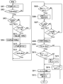
- FIG. 4 is a flowchart showing the operation of the return operation by the safety monitoring device 8 of FIG.
- the safety monitoring device 8 When starting the return operation, the safety monitoring device 8 outputs a descending operation command to the elevator control device 7 (step S401). Thereby, the elevator control device 7 causes the car 5 to descend.
- the car 5 travels at the maximum speed V2 determined by the specifications of the shock absorbers 13a and 13b. Is desirable.
- the overspeed monitoring reference V3 during the return operation is a constant level overspeed monitoring reference V3 (FIG. 2: second) that can safely stop the car 5 with the shock absorbers 13a and 13b regardless of the position of the car 5. Overspeed monitoring standard).
- the safety monitoring device 8 After outputting the descending operation command, the safety monitoring device 8 confirms whether the descending operation has been started (step S402). When the descent operation is not started, the safety monitoring device 8 outputs a descent operation command to the elevator control device 7 again.
- the safety monitoring device 8 checks whether the storage medium 19 is detected by the tag reader 20 (step S403). When the storage medium 19 is detected, the safety monitoring device 8 starts measuring the amount of movement of the car 5 from the detected storage medium 19 based on the signal from the governor encoder 12 (step S404).
- the safety monitoring device 8 confirms whether or not the second storage medium 19 is detected (step S405).
- the safety monitoring device 8 calculates the interval between the first storage medium 19 and the second storage medium 19 (step S406). Then, the calculated interval is compared with the information already stored by the learning operation, that is, the interval between the two adjacent storage media 19 (step S407).
- the safety monitoring device 8 determines the position of the car 5 at the position of the second storage medium 19 (step S408).
- the interval between the two storage media 19 is measured and compared with the interval stored in advance, and the comparison result and the storage are stored. Using the information stored in the medium 19, the position of the car 5 can be uniquely grasped. The current position of the car 5 is obtained by adding the amount of movement from the second storage medium 19 to the detection position of the second storage medium 19.
- the safety monitoring device 8 When the position of the car 5 is determined, the safety monitoring device 8 outputs a notification of completion of the return operation to the elevator control device 7 (step S409). Upon receiving this notification, the elevator control device 7 resumes normal operation services.
- the above operation is an operation when two storage media 19 can be detected by the descending operation. However, depending on the position of the car 5 at the start of the return operation, the two storage media 19 may not be detected by the descending operation. .
- the safety monitoring device 8 confirms whether or not the lower terminal floor switch 15 is detected before the first storage medium 19 is detected (step S410). Also, it is confirmed whether or not the lower terminal switch 15 is detected before the second storage medium 19 is detected (step S414).
- the safety monitoring device 8 detects the car 5 from the lower end floor switch 15 based on the signal from the governor encoder 12. The movement amount starts to be measured (step S411).
- the safety monitoring device 8 outputs an ascending operation command to the elevator control device 7 (step S412). Thereby, the elevator control apparatus 7 raises the car 5.
- the safety monitoring device 8 After outputting the ascending operation command, the safety monitoring device 8 checks whether or not the ascending operation is started (step S413). When the ascending operation is not started, the safety monitoring device 8 outputs the ascending operation command to the elevator control device 7 again.
- the safety monitoring device 8 checks whether the storage medium 19 is detected by the tag reader 20 (step S405). When the storage medium 19 is detected, the safety monitoring device 8 calculates the distance from the detection position of the lower terminal switch 15 to the detection position of the storage medium 19 detected first (step S406). Then, the calculated distance is compared with the distance information already stored by the learning operation, that is, the distance from the detection position of the lower terminal switch 15 to the detection position of the storage medium 19 adjacent thereto (step S407).
- the safety monitoring device 8 determines the position of the car 5 at the position of the storage medium 19 detected first (step S408). .
- the subsequent operation is the same as the case where the two storage media 19 can be detected only by the descending operation.
- the safety monitoring device 8 detects the first storage medium 19.
- the distance from the detection position of the medium 19 to the detection position of the lower terminal floor switch 15 is calculated (step S406).
- the calculated distance is compared with the information already stored by the learning operation, that is, the distance from the detection position of the lower terminal switch 15 to the detection position of the storage medium 19 adjacent thereto (step S407).
- the safety monitoring device 8 determines the position of the car 5 at the position of the lower terminal floor switch 15 (step S408).
- the subsequent operation is the same as the case where the two storage media 19 can be detected only by the descending operation.
- step S407 when the calculated value and the learned value cannot be matched, the safety monitoring device 8 outputs a command to stop the operation service to the elevator control device 7 (step S415). Thereby, the elevator control device 7 stops the operation service in accordance with the command from the safety monitoring device 8.
- the distance between the two points is measured by the signal from the double governor encoder 12, and compared with the value stored by the learning operation, the storage medium 19 and While performing failure diagnosis of the tag reader 20, the position of the car 5 can be determined.
- the safety monitoring device 8 instructs to stop the operation service. May be output again.
- the safety monitoring device 8 may perform a service for causing the car 5 to travel by limiting the traveling speed of the car 5 to a speed V2 lower than the normal traveling speed V0.
- the overspeed monitoring reference V3 is set in the safety monitoring device 8 according to the specifications of the shock absorbers 13a and 13b.
- FIG. 5 is an explanatory diagram showing intervals between the storage media 19 in the elevator apparatus of FIG.
- the two storage media 19 are detected.
- the car 5 starts the return operation from the position shown in FIG. 5 (immediately after passing through the uppermost storage medium 19 in FIG. 5), it takes about three minutes until the second storage medium 19 is detected. Must travel distance between storage media.
- the return is completed within the time T [min] allowed until the return.
- the storage media 19 are arranged at different intervals in the ascending / descending direction of the car 5, and the interval of the storage media 19 is stored in the safety monitoring device 8. Then, when the position of the car 5 can no longer be grasped, an operation for detecting the two storage media 19 is performed, and the interval between the detected storage media 19 is measured based on the signal from the governor encoder 12. The interval between the storage media 19 and the stored storage media 19 are compared, and the position of the car 5 is grasped using the comparison result and the information of the storage media. Therefore, when the position of the car 5 cannot be grasped, the car position detection with high reliability that can be used for safety monitoring can be performed using the storage medium 19.
- FIG. 6 is a block diagram showing an elevator apparatus according to Embodiment 2 of the present invention.
- a signal from the landing sensor 18 is input to the safety monitoring device 8 instead of the elevator control device 7. That is, information obtained by reading the landing plate 17 by the landing sensor 18 is used for safety monitoring.
- Other configurations are the same as those in the first embodiment.
- the signal of the landing sensor 18 may not be input only to the safety monitoring device 8 but may be branched and input to the elevator control device 7.
- a power source not shown
- a power source not shown
- safety monitoring is performed from the elevator control device 7. It is conceivable that a large current flows to the device 8 or from the safety monitoring device 8 to the elevator control device 7 and the control function of the control device 7 and the safety monitoring function of the safety monitoring device 8 are lost at the same time. For this reason, it is desirable to insulate between the control device 7 and the safety monitoring device 8 (the arrow portion between the control device 7 and the safety monitoring device 8 in FIG. 6) using a photocoupler.
- the method of detecting the position of the car 5 by the safety monitoring device 8 is basically the same as in the first embodiment.
- the safety monitoring device 8 according to the second embodiment starts from the reference position measured by the signal from the governor encoder 12. Is corrected using the position information of the landing plate 17 stored in advance. Thereby, the detection accuracy of the position of the car 5 can be improved as compared with the first embodiment.
- FIG. 7 is a flowchart showing the operation of the learning operation by the safety monitoring device 8 of FIG.
- the operations in steps S701 to S706 in FIG. 7 are the same as the operations in steps S301 to S306 in FIG.
- the safety monitoring device 8 of the second embodiment confirms whether the landing plate 17 is detected by the landing sensor 18 (step S707), and the storage medium 19 is detected by the tag reader 20. It is confirmed whether or not (step S708).
- the safety monitoring device 8 When the landing sensor 18 is detected, the safety monitoring device 8 combines the movement amount of the car 5 from the current reference position (the detection position of the lower terminal floor switch 15) and the number of detections of the landing sensor 18. (Step S709).
- the safety monitoring device 8 When the storage medium 19 is detected, the safety monitoring device 8 combines the movement amount of the car 5 from the reference position at that time (the detection position of the lower terminal switch 15) and the information of the storage medium 19 together. Store (step S710). These operations are continued until the safety monitoring device 8 detects the upper terminal floor switch 14 (step S711).
- step S713 the difference between the distance from the lower terminal floor switch 15 to the upper terminal floor switch 14 and the distance from the detection position of the lower terminal floor switch 15 to the detection position of the landing plate 17 is also obtained.
- step S714 the distance from the detection position of the landing plate 17 to the detection position of the upper terminal floor switch 14 is also stored.
- the safety monitoring device 8 confirms whether the landing sensor 17 is detected by the landing sensor 18 (step S718) and confirms whether the storage medium 19 is detected by the tag reader 20. (Step S719).
- the safety monitoring device 8 When the landing sensor 18 is detected, the safety monitoring device 8 combines the movement amount of the car 5 from the current reference position (the detection position of the upper terminal floor switch 14) and the number of detections of the landing sensor 18. (Step S720).
- the safety monitoring device 8 When the storage medium 19 is detected, the safety monitoring device 8 combines the movement amount of the car 5 from the reference position (detection position of the upper terminal switch 14) at that time and the information of the storage medium 19 together. Store (step S721). These operations are continued until the safety monitoring device 8 detects the lower terminal floor switch 15 (step S722).
- step S724 the difference between the distance from the upper terminal floor switch 14 to the lower terminal floor switch 15 and the distance from the detection position of the upper terminal floor switch 14 to the detection position of the landing plate 17 is also obtained.
- step S725 the distance from the detection position of the landing plate 17 to the detection position of the lower terminal floor switch 15 is also stored.
- the safety monitoring device 8 causes the distance from the detection position of each landing plate 17 to the detection position of the upper terminal floor switch 14, and the detection position of each landing plate 17 to the lower terminal floor switch 15.
- the distance to the detection position, the distance from the detection position of each storage medium 19 to the detection position of the upper terminal floor switch 14, and the distance from the detection position of each storage medium 19 to the detection position of the lower terminal floor switch 15 are stored.
- the interval between the landing plates 17, the interval between the storage media 19, and the distance from the detection position of the landing plate 17 to the detection position of the adjacent storage medium 19 can be stored.
- the safety monitoring device 8 since not only the position of each storage medium 19 but also the position of each landing plate 17 is stored at the same time, the safety monitoring device 8 recognizes the position of the car 5 using the signal of the landing sensor 18. can do.
- the position of the car 5 is determined basically by measuring the distance between the two storage media 19.
- the accuracy of the tag reader 20 that reads the storage medium 19 is lower than that of the landing sensor 18. Therefore, in the present embodiment, the landing sensor 18 is used in the return operation to determine the position of the car 5 with higher accuracy.
- FIG. 8 is a flowchart showing the operation of return operation by the safety monitoring device 8 of FIG.
- the operations in steps S801 to S804 in FIG. 8 are the same as the operations in steps S401 to S404 in FIG.
- the safety monitoring device 8 After the first storage medium 19 is detected by the descending operation, the safety monitoring device 8 continues the descending operation until the second storage medium 19 is detected. During this time, the safety monitoring device 8 checks whether the landing plate 17 is detected by the landing sensor 18 (step S805). When the landing sensor 18 is detected, the safety monitoring device 8 stores the distance from the detection position of the first storage medium 19 to the detection position of the landing sensor 18 (step S806).
- the landing plate 17 may be detected any number of times after the first storage medium 19 is detected. Each time, the safety monitoring device 8 stores the distance from the detection position of the first storage medium 19 to the detection position of the landing plate 17.
- the safety monitoring device 8 determines in which position in the hoistway 1 the detected landing plate 17 is located. Can be recognized.
- the safety monitoring device 8 calculates the interval between the first storage medium 19 and the second storage medium 19. (Step S808). Then, the calculated interval is compared with the information already stored by the learning operation, that is, the interval between the two adjacent storage media 19 (step S809).
- the safety monitoring device 8 confirms whether one or more landing plates 17 have been detected before the second storage medium 19 is detected. (Step S810).
- the safety monitoring device 8 determines the position of the car 5 at the last detected detection position of the landing plate 17 (step S811). At this time, the current position of the car 5 is obtained by adding the amount of movement from the landing plate 17 detected last to the detection position of the landing plate 17 detected last.
- the car 5 is run until the landing plate 17 is detected (step S818).
- the safety monitoring device 8 determines the position of the car 5 at the detection position of the landing plate 17.
- the safety monitoring device 8 When the position of the car 5 is determined, the safety monitoring device 8 outputs a notification of completion of the return operation to the elevator control device 7 (step S812). Upon receiving this notification, the elevator control device 7 resumes normal operation services.
- the safety monitoring device 8 confirms whether or not the lower terminal switch 15 is detected before the first storage medium 19 is detected (step S813). Also, it is confirmed whether or not the lower terminal switch 15 is detected before the second storage medium 19 is detected (step S817).
- steps S813 to S816 in FIG. 8 are the same as the operations in steps S410 to S413 in FIG.
- the safety monitoring device 8 continues the ascending operation until the storage medium 19 is detected. To do. During this time, the safety monitoring device 8 checks whether the landing plate 17 is detected by the landing sensor 18 (step S805).
- the safety monitoring device 8 stores the distance from the detection position of the lower terminal floor switch 15 to the detection position of the landing plate 17 (step S806).
- the landing plate 17 may be detected any number of times after detecting the lower terminal floor switch 15. Each time, the safety monitoring device 8 stores the distance from the detection position of the lower terminal floor switch 15 to the detection position of the landing plate 17.
- the safety monitoring device 8 calculates the distance from the detection position of the lower terminal switch 15 to the detection position of the storage medium 19 detected first (step S808). Then, the calculated distance is compared with the information already stored by the learning operation, that is, the distance from the detection position of the lower terminal switch 15 to the detection position of the storage medium 19 adjacent thereto (step S809).
- the safety monitoring device 8 checks whether one or more landing plates 17 have been detected before the storage medium 19 is detected (step S810).
- the safety monitoring device 8 determines the position of the car 5 at the last detected detection position of the landing plate 17 (step S811). At this time, the current position of the car 5 is obtained by adding the amount of movement from the landing plate 17 detected last to the detection position of the landing plate 17 detected last.
- the car 5 is caused to travel until the landing plate 17 is detected (step S818).
- the safety monitoring device 8 determines the position of the car 5 at the detection position of the landing plate 17.
- the safety monitoring device 8 detects the first storage medium 19.
- the distance from the detection position of the medium 19 to the detection position of the lower terminal floor switch 15 is calculated (step S808).
- the calculated distance is compared with the information already stored by the learning operation, that is, the distance from the detection position of the lower terminal switch 15 to the detection position of the storage medium 19 adjacent thereto (step S809).
- the safety monitoring device 8 determines the position of the car 5 at the detection position of the lower terminal floor switch 15 (step S811).
- step S809 the operation when the calculated value and the learned value are not matched is the same as in the first embodiment.
- the car in addition to the storage medium 19, by using information obtained by the combination of the landing plate 17 and the high-accuracy landing sensor 18, the car with higher accuracy than in the first embodiment.
- the position of 5 can be determined.
- Embodiment 3 FIG. Next, a third embodiment of the present invention will be described.
- the configuration of the elevator apparatus of the third embodiment is the same as that of the second embodiment.
- the learning operation by the safety monitoring device 8 is the same as that in the second embodiment.
- the safety monitoring device 8 according to the third embodiment is configured such that the distance from the detection position of the storage medium 19 stored by the learning operation to the detection position of the landing plate 17 adjacent thereto and the detected storage medium The position of the car 5 is grasped using the information 19 and the detected position information of the landing plate 17.
- the return operation by the safety monitoring device 8 of the third embodiment will be described.
- the position of the car 5 is determined by the detection position of the landing plate 17.
- the distance from the detection position of the storage medium 19 to the detection position of the landing plate 17 is measured to confirm the matching between the measured value and the learning value, and then the landing plate 17 The position of the car 5 is determined according to the detected position.
- FIG. 9 is a flowchart showing the return operation by the safety monitoring device 8 according to the third embodiment.
- the operations in steps S901 to S904 in FIG. 9 are the same as the operations in steps S401 to S404 in FIG.
- the safety monitoring device 8 continues the descending operation until the landing plate 17 is detected.
- the safety monitoring device 8 calculates the distance from the detection position of the storage medium 19 to the detection position of the landing plate 17 (step S905). S906). And the calculated distance is compared with the information already memorize
- the safety monitoring device 8 determines the position of the car 5 at the detection position of the landing plate 17 (step S908). At this time, the current position of the car 5 is obtained by adding the detected amount of movement from the landing plate 17 to the detected position of the detected landing plate 17.
- the safety monitoring device 8 When the position of the car 5 is determined, the safety monitoring device 8 outputs a notification of completion of the return operation to the elevator control device 7 (step S909). Upon receiving this notification, the elevator control device 7 resumes normal operation services.
- the safety monitoring device 8 confirms whether or not the lower terminal switch 15 has been detected before the storage medium 19 is detected (step S910). Also, it is confirmed whether or not the lower terminal floor switch 15 is detected before the landing plate 17 is detected (step S913).
- the safety monitoring device 8 continues the ascending operation until the storage medium 19 is detected.
- the operation after detecting the storage medium 19 is the same as in the descending operation.
- the safety monitoring device 8 detects the lower terminal floor switch 15 from the detection position of the storage medium 19. The distance to the detection position is calculated (step S906). Then, the calculated distance is compared with the information already stored by the learning operation, that is, the distance from the detection position of the lower terminal switch 15 to the detection position of the storage medium 19 adjacent thereto (step S907).
- the safety monitoring device 8 determines the position of the car 5 at the detection position of the lower terminal floor switch 15 (step S908).
- step S907 the operation when the calculated value and the learned value are not matched is the same as in the first and second embodiments.
- the position of the car 5 can be determined with high accuracy while diagnosing the information of the storage medium 19 based on the distance between the storage medium 19 and the landing plate 17 adjacent thereto. Therefore, when the position of the car 5 cannot be grasped, the car position detection with high reliability that can be used for safety monitoring can be performed using the storage medium 19.
- the movement detection means is not limited to the governor encoder.
- a rotation detector provided on the sheave around which the suspension means is wound, a distance sensor that continuously detects the movement of the car, or the like. It may be.
- the reading means is selected according to the type of the storage medium 19 and is not limited to a tag reader.
- the detected object is not limited to the landing plate 17, and the position sensor is not limited to the landing sensor 18.
- a magnetic detection object may be used.
- the monitoring target of the safety monitoring device is not limited to overspeed traveling, and for example, the presence or absence of door-opening traveling may be monitored.
- the layout and roping method of the elevator apparatus as a whole are not limited to the examples of FIGS. 1 and 6.
- the present invention can be applied to a 2: 1 roping elevator apparatus.
- the position and number of hoisting machines are not limited to the examples in FIGS.
- the present invention can be applied to various types of elevator devices such as a machine room-less elevator, a double deck elevator, a one-shaft multi-car elevator, or a skew elevator.
Landscapes
- Engineering & Computer Science (AREA)
- Automation & Control Theory (AREA)
- Computer Networks & Wireless Communication (AREA)
- Maintenance And Inspection Apparatuses For Elevators (AREA)
- Indicating And Signalling Devices For Elevators (AREA)
- Elevator Control (AREA)
Abstract
Description
かご、かごの移動に応じて信号を発生する移動検出手段、かごの昇降方向に互いに間隔をおいて昇降路内に配置されている複数の記憶媒体、かごに設けられており、記憶媒体に記憶されている情報を読み取る読取手段、及び移動検出手段からの信号を用いてかごの移動量及び位置を検出し、かごの運転状態の異常の有無を監視する安全監視装置を備え、記憶媒体は、かごの昇降方向に異なる間隔で配置されており、安全監視装置には、記憶媒体の間隔が記憶されており、安全監視装置は、かごの位置を把握できなくなったとき、2つの記憶媒体を検出する運転を行い、検出された記憶媒体の間隔を移動検出手段からの信号に基づいて測定し、測定された記憶媒体の間隔と記憶されている記憶媒体の間隔とを比較し、その比較結果と記憶媒体の情報とを用いてかごの位置を把握する。
また、この発明に係るエレベータ装置は、かご、記かごの移動に応じて信号を発生する移動検出手段、かごの昇降方向に互いに間隔をおいて昇降路内に配置されている複数の記憶媒体、かごに設けられており、記憶媒体に記憶されている情報を読み取る読取手段、かごの昇降方向に互いに間隔をおいて昇降路内に配置されている複数の被検出体、かごに設けられており、被検出体を検出する位置センサ、及び移動検出手段からの信号を用いてかごの移動量及び位置を検出し、かごの運転状態の異常の有無を監視する安全監視装置を備え、安全監視装置には、記憶媒体の検出位置からそれに隣接する被検出体の検出位置までの距離と、被検出体の位置情報とが記憶されており、安全監視装置は、かごの位置を把握できなくなったとき、記憶媒体と被検出体とを検出する運転を行い、記憶媒体の検出位置から被検出体の検出位置までの距離を移動検出手段からの信号に基づいて測定し、測定された距離を記憶されている情報と比較し、その比較結果と記憶媒体の情報と被検出体の位置情報とを用いてかごの位置を把握する。
また、この発明のエレベータ装置は、安全監視装置に、記憶媒体の検出位置からそれに隣接する被検出体の検出位置までの距離と、被検出体の位置情報とが記憶されており、かごの位置を把握できなくなったとき、記憶媒体と被検出体とを検出する運転を行い、記憶媒体の検出位置から被検出体の検出位置までの距離を移動検出手段からの信号に基づいて測定し、測定された距離を記憶されている情報と比較し、その比較結果と記憶媒体の情報と被検出体の位置情報とを用いてかごの位置を把握するので、かごの位置を把握できなくなった場合に、記憶媒体を用いて、安全監視にも使用できる信頼性の高いかご位置検出を行うことができる。
実施の形態1.
図1はこの発明の実施の形態1によるエレベータ装置を示す構成図である。図において、昇降路1の上部には、機械室2が設けられている。機械室2には、巻上機3が設けられている。巻上機3は、駆動シーブ、駆動シーブを回転させる巻上機モータ、及び駆動シーブの回転を制動する巻上機ブレーキを有している。
上記のような安全監視を実行するため、安全監視装置8は、上部終端階スイッチ14、下部終端階スイッチ15、及び記憶媒体19の位置を記憶する学習運転を実施する。即ち、安全監視装置8による運転モードには、学習運転モードが含まれている。
ここで、安全監視装置8は、例えば通常運転中に安全監視装置8に対する電力供給が断たれた場合など、かご5の位置を把握できなくなったとき、そのときのかご5の位置情報を記憶する手順を踏むことなく機能を停止する。
次に、任意に配置すると述べた記憶媒体19について、隣接する2つの記憶媒体19間の具体的な間隔について図5を参照して説明する。図5は図1のエレベータ装置における記憶媒体19の間隔を示す説明図である。
X=(0.5×a×t12+V2(T-t1))/2[m]
以内とすることで、復帰までに許容される時間T[min]以内に復帰が完了する。
次に、図6はこの発明の実施の形態2によるエレベータ装置を示す構成図である。実施の形態2では、着床センサ18からの信号が、エレベータ制御装置7ではなく安全監視装置8に入力されている。つまり、着床プレート17を着床センサ18により読み取った情報が安全監視に使用される。その他の構成は、実施の形態1と同様である。
上記のような位置情報の補正を行うため、安全監視装置8は、学習運転において着床プレート17の検出位置も記憶する。図7は図6の安全監視装置8による学習運転の動作を示すフローチャートである。図7におけるステップS701~S706の動作は、図3におけるステップS301~S306の動作と同様である。
次に、実施の形態2の安全監視装置8による復帰運転について説明する。実施の形態1では、基本的に2つの記憶媒体19の間の距離を計測することでかご5の位置を確定した。しかし、記憶媒体19を読み取るタグリーダ20の精度は、着床センサ18に比べると低い。そこで、本実施の形態では、復帰運転において着床センサ18を用い、より高精度でかご5の位置を確定させる。
次に、この発明の実施の形態3について説明する。実施の形態3のエレベータ装置の構成は、実施の形態2と同様である。また、安全監視装置8による学習運転も、実施の形態2と同様である。但し、実施の形態3の安全監視装置8は、復帰運転において、学習運転によって記憶された記憶媒体19の検出位置からそれに隣接する着床プレート17の検出位置までの距離と、検出された記憶媒体19の情報と、検出された着床プレート17の位置情報とを用いてかご5の位置を把握する。
以下、実施の形態3の安全監視装置8による復帰運転について説明する。実施の形態2では、2つの記憶媒体19の間の距離を計測して計測値と学習値との整合を確認した後、着床プレート17の検出位置によってかご5の位置を確定した。これに対して、実施の形態3では、記憶媒体19の検出位置から着床プレート17の検出位置までの距離を計測して計測値と学習値との整合を確認した後、その着床プレート17の検出位置によってかご5の位置を確定する。
また、読取手段は、記憶媒体19の種類に応じて選択されるものであり、タグリーダに限定されない。
さらに、被検出体は着床プレート17に限定されるものではなく、位置センサも着床センサ18に限定されるものではない。例えば、被検出体として、昇降路内の任意の位置に設けられたプレートを用いてもよい。また、磁気式の被検出体を用いてもよい。
さらにまた、安全監視装置の監視対象は、過速度走行に限定されるものではなく、例えば戸開走行の有無を監視してもよい。
また、エレベータ装置全体の機器のレイアウト及びローピング方式等は、図1及び図6の例に限定されるものではない。例えば、この発明は、2:1ローピングのエレベータ装置にも適用できる。また、例えば巻上機の位置及び数等も図1及び図6の例に限定されない。
さらに、この発明は、例えば機械室レスエレベータ、ダブルデッキエレベータ、ワンシャフトマルチカー方式のエレベータ、又は斜行エレベータなど、種々のタイプのエレベータ装置に適用できる。
Claims (11)
- かご、
前記かごの移動に応じて信号を発生する移動検出手段、
前記かごの昇降方向に互いに間隔をおいて昇降路内に配置されている複数の記憶媒体、
前記かごに設けられており、前記記憶媒体に記憶されている情報を読み取る読取手段、及び
前記移動検出手段からの信号を用いて前記かごの移動量及び位置を検出し、前記かごの運転状態の異常の有無を監視する安全監視装置
を備え、
前記記憶媒体は、前記かごの昇降方向に異なる間隔で配置されており、
前記安全監視装置には、前記記憶媒体の間隔が記憶されており、
前記安全監視装置は、前記かごの位置を把握できなくなったとき、2つの前記記憶媒体を検出する運転を行い、検出された前記記憶媒体の間隔を前記移動検出手段からの信号に基づいて測定し、測定された前記記憶媒体の間隔と記憶されている前記記憶媒体の間隔とを比較し、その比較結果と前記記憶媒体の情報とを用いて前記かごの位置を把握するエレベータ装置。 - 前記かごが終端階に到達したことを検出する終端階かご検出手段をさらに備え、
前記安全監視装置による運転モードには、学習運転モードが含まれており、
前記安全監視装置は、前記学習運転モードでは、前記終端階かご検出手段の検出位置から前記記憶媒体の検出位置までの距離を前記移動検出手段からの信号により測定し、前記終端階かご検出手段の検出位置から前記記憶媒体の検出位置までの距離と前記記憶媒体の間隔とを記憶する請求項1記載のエレベータ装置。 - 前記安全監視装置は、前記かごの位置を把握できなくなったとき、1つ目の前記記憶媒体が検出された後、2つ目の前記記憶媒体が検出される前に前記かごが終端階に達したことが検出されると、1つ目の前記記憶媒体の検出位置から前記終端階かご検出手段の検出位置までの距離を前記移動検出手段からの信号に基づいて測定し、測定された距離と記憶されている情報とを比較し、比較結果に応じて前記終端階かご検出手段の検出位置で前記かごの位置を確定する請求項2記載のエレベータ装置。
- 前記かごの昇降方向に互いに間隔をおいて前記昇降路内に配置されている複数の被検出体、及び
前記かごに設けられており、前記被検出体を検出する位置センサ
をさらに備え、
前記安全監視装置は、前記かごの位置を把握できなくなったとき、2つの前記記憶媒体に加えて前記被検出体を検出する運転を行い、前記被検出体の位置情報も用いて前記かごの位置を把握する請求項1記載のエレベータ装置。 - 前記かごが終端階に到達したことを検出する終端階かご検出手段をさらに備え、
前記安全監視装置による運転モードには、学習運転モードが含まれており、
前記安全監視装置は、前記学習運転モードでは、前記終端階かご検出手段の検出位置から前記記憶媒体の検出位置までの距離と、前記終端階かご検出手段の検出位置から前記被検出体の検出位置までの距離とを、前記移動検出手段からの信号により測定し、前記終端階かご検出手段の検出位置から前記記憶媒体の検出位置までの距離と、前記記憶媒体の間隔と、前記終端階かご検出手段の検出位置から前記被検出体の検出位置までの距離とを記憶する請求項4記載のエレベータ装置。 - かご、
前記かごの移動に応じて信号を発生する移動検出手段、
前記かごの昇降方向に互いに間隔をおいて昇降路内に配置されている複数の記憶媒体、
前記かごに設けられており、前記記憶媒体に記憶されている情報を読み取る読取手段、
前記かごの昇降方向に互いに間隔をおいて前記昇降路内に配置されている複数の被検出体、
前記かごに設けられており、前記被検出体を検出する位置センサ、及び
前記移動検出手段からの信号を用いて前記かごの移動量及び位置を検出し、前記かごの運転状態の異常の有無を監視する安全監視装置
を備え、
前記安全監視装置には、前記記憶媒体の検出位置からそれに隣接する前記被検出体の検出位置までの距離と、前記被検出体の位置情報とが記憶されており、
前記安全監視装置は、前記かごの位置を把握できなくなったとき、前記記憶媒体と前記被検出体とを検出する運転を行い、前記記憶媒体の検出位置から前記被検出体の検出位置までの距離を前記移動検出手段からの信号に基づいて測定し、測定された距離を記憶されている情報と比較し、その比較結果と前記記憶媒体の情報と前記被検出体の位置情報とを用いて前記かごの位置を把握するエレベータ装置。 - 前記かごが終端階に到達したことを検出する終端階かご検出手段をさらに備え、
前記安全監視装置による運転モードには、学習運転モードが含まれており、
前記安全監視装置は、前記学習運転モードでは、前記終端階かご検出手段の検出位置から前記記憶媒体の検出位置までの距離と、前記終端階かご検出手段の検出位置から前記被検出体の検出位置までの距離とを、前記移動検出手段からの信号により測定し、前記終端階かご検出手段の検出位置から前記記憶媒体までの距離と、前記記憶媒体の間隔と、前記終端階かご検出手段の検出位置から前記被検出体の検出位置までの距離と、前記記憶媒体の検出位置からそれに隣接する前記被検出体の検出位置までの距離とを記憶する請求項6記載のエレベータ装置。 - 前記安全監視装置は、前記かごの位置を把握できなくなったとき、前記記憶媒体が検出された後、前記被検出体が検出される前に前記かごが終端階に達したことが検出されると、前記記憶媒体の検出位置から前記終端階かご検出手段の検出位置までの距離を前記移動検出手段からの信号に基づいて測定し、測定された距離と記憶されている情報とを比較し、比較結果に応じて前記終端階かご検出手段の検出位置で前記かごの位置を確定する請求項7記載のエレベータ装置。
- 前記被検出体は着床プレートであり、前記位置センサは着床センサである請求項4から請求項8までのいずれか1項に記載のエレベータ装置。
- 前記安全監視装置は、
前記かごの位置を把握しているときに、前記昇降路の終端階付近において終端方向へ向かって連続的に低くなる第1の過速度監視基準により、前記かごの過速度走行の有無を監視し、
前記かごの位置を把握できなくなったときに、前記かごの位置を把握するための運転により、前記かごの位置を把握するために使用される機器の故障が検出されると、前記かごの走行速度を正常な走行速度よりも低い速度に制限するとともに、前記第1の過速度監視基準よりも低い一定レベルの第2の過速度監視基準により、前記かごの過速度走行の有無を監視する請求項1から請求項9までのいずれか1項に記載のエレベータ装置。 - 前記移動検出手段は、ロータリエンコーダであり、
前記記憶媒体は、個体識別情報を記憶しているとともに、無線通信可能になっており、
前記読取手段は、前記記憶媒体の情報を非接触で読み取るリーダであり、
前記安全監視装置には、前記個体識別情報と前記昇降路内の位置とを関連付ける情報が記憶されている請求項1から請求項10までのいずれか1項に記載のエレベータ装置。
Priority Applications (5)
| Application Number | Priority Date | Filing Date | Title |
|---|---|---|---|
| US14/761,533 US9809419B2 (en) | 2013-01-23 | 2013-11-13 | Elevator apparatus |
| JP2014558445A JP6008995B2 (ja) | 2013-01-23 | 2013-11-13 | エレベータ装置 |
| KR1020157022601A KR101781279B1 (ko) | 2013-01-23 | 2013-11-13 | 엘리베이터 장치 |
| DE112013006482.0T DE112013006482B4 (de) | 2013-01-23 | 2013-11-13 | Aufzugsvorrichtung |
| CN201380071133.1A CN104936879B (zh) | 2013-01-23 | 2013-11-13 | 电梯装置 |
Applications Claiming Priority (2)
| Application Number | Priority Date | Filing Date | Title |
|---|---|---|---|
| JP2013010302 | 2013-01-23 | ||
| JP2013-010302 | 2013-01-23 |
Publications (1)
| Publication Number | Publication Date |
|---|---|
| WO2014115402A1 true WO2014115402A1 (ja) | 2014-07-31 |
Family
ID=51227206
Family Applications (1)
| Application Number | Title | Priority Date | Filing Date |
|---|---|---|---|
| PCT/JP2013/080674 WO2014115402A1 (ja) | 2013-01-23 | 2013-11-13 | エレベータ装置 |
Country Status (6)
| Country | Link |
|---|---|
| US (1) | US9809419B2 (ja) |
| JP (1) | JP6008995B2 (ja) |
| KR (1) | KR101781279B1 (ja) |
| CN (1) | CN104936879B (ja) |
| DE (1) | DE112013006482B4 (ja) |
| WO (1) | WO2014115402A1 (ja) |
Cited By (4)
| Publication number | Priority date | Publication date | Assignee | Title |
|---|---|---|---|---|
| JP6471202B1 (ja) * | 2017-09-19 | 2019-02-13 | 東芝エレベータ株式会社 | エレベータの制御システム |
| CN109850705A (zh) * | 2017-11-30 | 2019-06-07 | 株式会社日立制作所 | 电梯用控制装置 |
| US11548761B2 (en) * | 2018-07-31 | 2023-01-10 | Otis Elevator Company | Detecting elevator mechanics in elevator systems |
| WO2023135648A1 (ja) * | 2022-01-11 | 2023-07-20 | 三菱電機株式会社 | 位置演算装置およびエレベーターシステム |
Families Citing this family (26)
| Publication number | Priority date | Publication date | Assignee | Title |
|---|---|---|---|---|
| FI123145B (fi) * | 2012-01-23 | 2012-11-30 | Kone Corp | Menetelmä ja järjestely kuljetusjärjestelmän toimintakunnon valvomiseksi |
| US9963321B2 (en) * | 2013-05-16 | 2018-05-08 | Mitsubishi Electric Corporation | Elevator device |
| EP2842899B1 (de) * | 2013-08-29 | 2016-11-02 | Cedes AG | Messband für eine Aufzugvorrichtung |
| DE112013007449T5 (de) * | 2013-09-20 | 2016-06-16 | Mitsubishi Electric Corporation | Aufzugvorrichtung |
| EP2990369A1 (en) * | 2014-08-29 | 2016-03-02 | Inventio AG | Method and arrangement for determining elevator data based on the position of an elevator cabin |
| WO2016038681A1 (ja) * | 2014-09-09 | 2016-03-17 | 三菱電機株式会社 | エレベーター装置 |
| CN106794958B (zh) * | 2014-10-22 | 2019-01-15 | 三菱电机株式会社 | 电梯的控制装置 |
| PL3230189T3 (pl) * | 2014-12-10 | 2020-10-19 | Inventio Ag | Układ windy z systemem monitorowania bezpieczeństwa z hierarchią master-slave |
| KR102126932B1 (ko) * | 2015-07-22 | 2020-06-26 | 미쓰비시덴키 가부시키가이샤 | 엘리베이터 장치 |
| US10968076B2 (en) * | 2015-07-28 | 2021-04-06 | Otis Elevator Company | Elevator maintenance from inside elevator car |
| CN108349691B (zh) * | 2015-10-22 | 2020-08-28 | 通力股份公司 | 具有安全配置的升降机和用于在升降机井道的上部部分中建立安全工作空间的方法 |
| JP6626808B2 (ja) * | 2016-09-28 | 2019-12-25 | 株式会社日立製作所 | エレベーター制御システム |
| US20180162693A1 (en) * | 2016-12-13 | 2018-06-14 | Otis Elevator Company | Speed detection means for elevator or counterweight |
| JP6641308B2 (ja) * | 2017-01-25 | 2020-02-05 | 株式会社日立製作所 | エレベーター |
| EP3360833B1 (en) * | 2017-02-10 | 2019-10-16 | KONE Corporation | A method, a safety control unit and an elevator system for defining absolute position information of an elevator car |
| WO2018150786A1 (ja) * | 2017-02-17 | 2018-08-23 | 三菱電機株式会社 | エレベーター装置 |
| EP3366626B1 (en) * | 2017-02-22 | 2021-01-06 | Otis Elevator Company | Elevator safety system and method of monitoring an elevator system |
| US10577222B2 (en) * | 2017-05-12 | 2020-03-03 | Otis Elevator Company | Coded elevator inspection and positioning systems and methods |
| EP3434634B2 (en) * | 2017-07-25 | 2024-07-03 | Otis Elevator Company | Elevator safety device |
| US11535488B2 (en) | 2017-08-28 | 2022-12-27 | Otis Elevator Company | Elevator position detection systems |
| CN108861903B (zh) * | 2018-05-23 | 2020-06-23 | 首钢滦南马城矿业有限责任公司 | 一种矿井提升罐笼泊位系统及方法 |
| US20200071126A1 (en) * | 2018-08-30 | 2020-03-05 | Otis Elevator Company | Determining elevator car location using radio frequency identification |
| US11649136B2 (en) | 2019-02-04 | 2023-05-16 | Otis Elevator Company | Conveyance apparatus location determination using probability |
| CN111689316B (zh) * | 2020-05-28 | 2022-08-12 | 日立楼宇技术(广州)有限公司 | 电梯轿厢位置确定方法、装置、计算机设备和存储介质 |
| CN111762645B (zh) * | 2020-07-28 | 2022-06-07 | 北京三快在线科技有限公司 | 电梯轿厢位置检测系统、方法及装置 |
| CN113844964B (zh) * | 2021-10-11 | 2023-08-22 | 上海擎朗智能科技有限公司 | 机器人乘梯的控制方法、装置、电子设备和存储介质 |
Citations (4)
| Publication number | Priority date | Publication date | Assignee | Title |
|---|---|---|---|---|
| JP2006256795A (ja) * | 2005-03-17 | 2006-09-28 | Yaskawa Electric Corp | エレベータの運転制御方法 |
| WO2008062500A1 (en) * | 2006-11-20 | 2008-05-29 | Mitsubishi Electric Corporation | Elevator system |
| WO2010084581A1 (ja) * | 2009-01-21 | 2010-07-29 | 三菱電機株式会社 | エレベータ装置 |
| JP2011102163A (ja) * | 2009-11-10 | 2011-05-26 | Hitachi Ltd | エレベーターシステム及びエレベーターシステムの制御方法 |
Family Cites Families (20)
| Publication number | Priority date | Publication date | Assignee | Title |
|---|---|---|---|---|
| US3779346A (en) * | 1972-05-17 | 1973-12-18 | Westinghouse Electric Corp | Terminal slowdown control for elevator system |
| US4317506A (en) * | 1980-06-10 | 1982-03-02 | Westinghouse Electric Corp. | Elevator system |
| US4436185A (en) * | 1982-04-20 | 1984-03-13 | Westinghouse Electric Corp. | Elevator system |
| US4494628A (en) * | 1983-08-17 | 1985-01-22 | Westinghouse Electric Corp. | Elevator system |
| US5153390A (en) * | 1991-03-15 | 1992-10-06 | Otis Elevator Company | Method for avoiding terminal landing position initialization after power loss |
| AU2003212922A1 (en) * | 2003-02-03 | 2004-08-30 | Otis Elevator Company | Passive ultrasonic rfid elevator positioning reference system |
| US7493991B2 (en) * | 2003-05-30 | 2009-02-24 | Otis Elevator Company | Electromagnetic/ultrasonic roll-calling/answering (EURA) system for elevator positioning |
| US7600613B2 (en) | 2003-10-31 | 2009-10-13 | Otis Elevator Company | RFID and low resolution CCD sensor based positioning system |
| SG120250A1 (en) * | 2004-08-12 | 2006-03-28 | Inventio Ag | Elevator installation with a car and a device for determining a car position and method for operating such an elevator installation |
| FI119878B (fi) * | 2005-02-04 | 2009-04-30 | Kone Corp | Järjestelmä ja menetelmä hissin turvallisuuden parantamiseksi |
| JP4468224B2 (ja) | 2005-03-30 | 2010-05-26 | 株式会社日立製作所 | エレベータの位置検出システム及び方法 |
| JP2007290868A (ja) * | 2006-04-20 | 2007-11-08 | Inventio Ag | エレベータ設備の複数の操作ユニットの階関連付けを設定する方法 |
| EP2067732A1 (en) | 2007-12-07 | 2009-06-10 | Inventio Ag | Elevator cabin position detection system |
| FI120449B (fi) | 2008-08-12 | 2009-10-30 | Kone Corp | Järjestely ja menetelmä hissikorin paikan määrittämiseksi |
| FI121663B (fi) * | 2009-10-09 | 2011-02-28 | Kone Corp | Mittausjärjestely, valvontajärjestely sekä hissijärjestelmä |
| WO2011148411A1 (ja) * | 2010-05-26 | 2011-12-01 | 株式会社 日立製作所 | 電子安全エレベータ |
| KR101545800B1 (ko) * | 2011-06-09 | 2015-08-19 | 미쓰비시덴키 가부시키가이샤 | 엘리베이터 장치 |
| FI123145B (fi) | 2012-01-23 | 2012-11-30 | Kone Corp | Menetelmä ja järjestely kuljetusjärjestelmän toimintakunnon valvomiseksi |
| WO2013156670A1 (en) * | 2012-04-20 | 2013-10-24 | Kone Corporation | Testing apparatus and safety arrangement |
| DE112013007449T5 (de) * | 2013-09-20 | 2016-06-16 | Mitsubishi Electric Corporation | Aufzugvorrichtung |
-
2013
- 2013-11-13 WO PCT/JP2013/080674 patent/WO2014115402A1/ja active Application Filing
- 2013-11-13 CN CN201380071133.1A patent/CN104936879B/zh active Active
- 2013-11-13 US US14/761,533 patent/US9809419B2/en not_active Expired - Fee Related
- 2013-11-13 KR KR1020157022601A patent/KR101781279B1/ko active IP Right Grant
- 2013-11-13 JP JP2014558445A patent/JP6008995B2/ja active Active
- 2013-11-13 DE DE112013006482.0T patent/DE112013006482B4/de not_active Expired - Fee Related
Patent Citations (4)
| Publication number | Priority date | Publication date | Assignee | Title |
|---|---|---|---|---|
| JP2006256795A (ja) * | 2005-03-17 | 2006-09-28 | Yaskawa Electric Corp | エレベータの運転制御方法 |
| WO2008062500A1 (en) * | 2006-11-20 | 2008-05-29 | Mitsubishi Electric Corporation | Elevator system |
| WO2010084581A1 (ja) * | 2009-01-21 | 2010-07-29 | 三菱電機株式会社 | エレベータ装置 |
| JP2011102163A (ja) * | 2009-11-10 | 2011-05-26 | Hitachi Ltd | エレベーターシステム及びエレベーターシステムの制御方法 |
Cited By (5)
| Publication number | Priority date | Publication date | Assignee | Title |
|---|---|---|---|---|
| JP6471202B1 (ja) * | 2017-09-19 | 2019-02-13 | 東芝エレベータ株式会社 | エレベータの制御システム |
| JP2019052042A (ja) * | 2017-09-19 | 2019-04-04 | 東芝エレベータ株式会社 | エレベータの制御システム |
| CN109850705A (zh) * | 2017-11-30 | 2019-06-07 | 株式会社日立制作所 | 电梯用控制装置 |
| US11548761B2 (en) * | 2018-07-31 | 2023-01-10 | Otis Elevator Company | Detecting elevator mechanics in elevator systems |
| WO2023135648A1 (ja) * | 2022-01-11 | 2023-07-20 | 三菱電機株式会社 | 位置演算装置およびエレベーターシステム |
Also Published As
| Publication number | Publication date |
|---|---|
| DE112013006482T5 (de) | 2015-10-29 |
| KR20150108909A (ko) | 2015-09-30 |
| JPWO2014115402A1 (ja) | 2017-01-26 |
| JP6008995B2 (ja) | 2016-10-19 |
| CN104936879A (zh) | 2015-09-23 |
| US20150336768A1 (en) | 2015-11-26 |
| US9809419B2 (en) | 2017-11-07 |
| DE112013006482B4 (de) | 2019-05-02 |
| KR101781279B1 (ko) | 2017-09-22 |
| CN104936879B (zh) | 2017-04-19 |
Similar Documents
| Publication | Publication Date | Title |
|---|---|---|
| JP6008995B2 (ja) | エレベータ装置 | |
| JP6120977B2 (ja) | エレベータ装置 | |
| CN102947210B (zh) | 电梯系统 | |
| JP6351854B2 (ja) | エレベータ装置 | |
| JP5442679B2 (ja) | エレベーター用制御装置 | |
| CN102725218B (zh) | 设置有安全位置传感器的电梯 | |
| JP2011102163A (ja) | エレベーターシステム及びエレベーターシステムの制御方法 | |
| CN104860148B (zh) | 电梯系统 | |
| JP6987255B2 (ja) | エレベータ診断システム | |
| EP3438033B1 (en) | Elevator system | |
| JP6272201B2 (ja) | エレベータ | |
| WO2011001764A1 (ja) | エレベータ装置 | |
| JP2019099324A (ja) | エレベーター用制御装置 | |
| JP2020029314A (ja) | エレベーター診断システム、および、エレベーターの診断方法 | |
| JP5897212B2 (ja) | エレベータ装置及びその制御方法 | |
| JP2013220926A (ja) | エレベータのかご位置検出システム | |
| JP6828129B1 (ja) | ロープ異常診断システム、ロープ異常診断方法、及びプログラム | |
| WO2011074084A1 (ja) | エレベーターの運転装置 | |
| JP2013043723A (ja) | エレベータの救出運転装置および救出運転方法 | |
| KR20130003992U (ko) | 알에프아이디 칩을 이용한 엘리베이터의 위치제어 시스템 |
Legal Events
| Date | Code | Title | Description |
|---|---|---|---|
| 121 | Ep: the epo has been informed by wipo that ep was designated in this application |
Ref document number: 13872927 Country of ref document: EP Kind code of ref document: A1 |
|
| ENP | Entry into the national phase |
Ref document number: 2014558445 Country of ref document: JP Kind code of ref document: A |
|
| WWE | Wipo information: entry into national phase |
Ref document number: 14761533 Country of ref document: US |
|
| WWE | Wipo information: entry into national phase |
Ref document number: 1120130064820 Country of ref document: DE Ref document number: 112013006482 Country of ref document: DE |
|
| ENP | Entry into the national phase |
Ref document number: 20157022601 Country of ref document: KR Kind code of ref document: A |
|
| 122 | Ep: pct application non-entry in european phase |
Ref document number: 13872927 Country of ref document: EP Kind code of ref document: A1 |